EP3135940A1 - Shaft coupling structure and electric power steering system - Google Patents
Shaft coupling structure and electric power steering system Download PDFInfo
- Publication number
- EP3135940A1 EP3135940A1 EP16181250.8A EP16181250A EP3135940A1 EP 3135940 A1 EP3135940 A1 EP 3135940A1 EP 16181250 A EP16181250 A EP 16181250A EP 3135940 A1 EP3135940 A1 EP 3135940A1
- Authority
- EP
- European Patent Office
- Prior art keywords
- shaft
- coupling structure
- axial direction
- protruding
- circumferential direction
- Prior art date
- Legal status (The legal status is an assumption and is not a legal conclusion. Google has not performed a legal analysis and makes no representation as to the accuracy of the status listed.)
- Withdrawn
Links
- 230000008878 coupling Effects 0.000 title claims abstract description 81
- 238000010168 coupling process Methods 0.000 title claims abstract description 81
- 238000005859 coupling reaction Methods 0.000 title claims abstract description 81
- 239000011347 resin Substances 0.000 claims description 20
- 229920005989 resin Polymers 0.000 claims description 20
- 230000009467 reduction Effects 0.000 claims description 16
- 239000002184 metal Substances 0.000 claims description 7
- 238000000465 moulding Methods 0.000 claims description 4
- 230000005540 biological transmission Effects 0.000 description 12
- 230000007246 mechanism Effects 0.000 description 9
- 230000006835 compression Effects 0.000 description 8
- 238000007906 compression Methods 0.000 description 8
- 238000005096 rolling process Methods 0.000 description 5
- 239000000463 material Substances 0.000 description 3
- 230000002093 peripheral effect Effects 0.000 description 3
- 238000010586 diagram Methods 0.000 description 2
- 230000000694 effects Effects 0.000 description 2
- 239000007769 metal material Substances 0.000 description 2
- 230000004323 axial length Effects 0.000 description 1
- 230000007423 decrease Effects 0.000 description 1
- 230000006866 deterioration Effects 0.000 description 1
- 230000000452 restraining effect Effects 0.000 description 1
- 238000011144 upstream manufacturing Methods 0.000 description 1
Images



Classifications
-
- B—PERFORMING OPERATIONS; TRANSPORTING
- B62—LAND VEHICLES FOR TRAVELLING OTHERWISE THAN ON RAILS
- B62D—MOTOR VEHICLES; TRAILERS
- B62D5/00—Power-assisted or power-driven steering
- B62D5/04—Power-assisted or power-driven steering electrical, e.g. using an electric servo-motor connected to, or forming part of, the steering gear
- B62D5/043—Power-assisted or power-driven steering electrical, e.g. using an electric servo-motor connected to, or forming part of, the steering gear characterised by clutch means between driving element, e.g. motor, and driven element, e.g. steering column or steering gear
-
- B—PERFORMING OPERATIONS; TRANSPORTING
- B62—LAND VEHICLES FOR TRAVELLING OTHERWISE THAN ON RAILS
- B62D—MOTOR VEHICLES; TRAILERS
- B62D5/00—Power-assisted or power-driven steering
- B62D5/04—Power-assisted or power-driven steering electrical, e.g. using an electric servo-motor connected to, or forming part of, the steering gear
- B62D5/0421—Electric motor acting on or near steering gear
-
- F—MECHANICAL ENGINEERING; LIGHTING; HEATING; WEAPONS; BLASTING
- F16—ENGINEERING ELEMENTS AND UNITS; GENERAL MEASURES FOR PRODUCING AND MAINTAINING EFFECTIVE FUNCTIONING OF MACHINES OR INSTALLATIONS; THERMAL INSULATION IN GENERAL
- F16D—COUPLINGS FOR TRANSMITTING ROTATION; CLUTCHES; BRAKES
- F16D3/00—Yielding couplings, i.e. with means permitting movement between the connected parts during the drive
- F16D3/50—Yielding couplings, i.e. with means permitting movement between the connected parts during the drive with the coupling parts connected by one or more intermediate members
- F16D3/64—Yielding couplings, i.e. with means permitting movement between the connected parts during the drive with the coupling parts connected by one or more intermediate members comprising elastic elements arranged between substantially-radial walls of both coupling parts
- F16D3/68—Yielding couplings, i.e. with means permitting movement between the connected parts during the drive with the coupling parts connected by one or more intermediate members comprising elastic elements arranged between substantially-radial walls of both coupling parts the elements being made of rubber or similar material
-
- B—PERFORMING OPERATIONS; TRANSPORTING
- B62—LAND VEHICLES FOR TRAVELLING OTHERWISE THAN ON RAILS
- B62D—MOTOR VEHICLES; TRAILERS
- B62D3/00—Steering gears
- B62D3/02—Steering gears mechanical
- B62D3/04—Steering gears mechanical of worm type
-
- B—PERFORMING OPERATIONS; TRANSPORTING
- B62—LAND VEHICLES FOR TRAVELLING OTHERWISE THAN ON RAILS
- B62D—MOTOR VEHICLES; TRAILERS
- B62D3/00—Steering gears
- B62D3/02—Steering gears mechanical
- B62D3/04—Steering gears mechanical of worm type
- B62D3/06—Steering gears mechanical of worm type with screw and nut
-
- B—PERFORMING OPERATIONS; TRANSPORTING
- B62—LAND VEHICLES FOR TRAVELLING OTHERWISE THAN ON RAILS
- B62D—MOTOR VEHICLES; TRAILERS
- B62D5/00—Power-assisted or power-driven steering
- B62D5/04—Power-assisted or power-driven steering electrical, e.g. using an electric servo-motor connected to, or forming part of, the steering gear
- B62D5/0442—Conversion of rotational into longitudinal movement
- B62D5/0454—Worm gears
-
- F—MECHANICAL ENGINEERING; LIGHTING; HEATING; WEAPONS; BLASTING
- F16—ENGINEERING ELEMENTS AND UNITS; GENERAL MEASURES FOR PRODUCING AND MAINTAINING EFFECTIVE FUNCTIONING OF MACHINES OR INSTALLATIONS; THERMAL INSULATION IN GENERAL
- F16D—COUPLINGS FOR TRANSMITTING ROTATION; CLUTCHES; BRAKES
- F16D11/00—Clutches in which the members have interengaging parts
- F16D11/08—Clutches in which the members have interengaging parts actuated by moving a non-rotating part axially
- F16D11/10—Clutches in which the members have interengaging parts actuated by moving a non-rotating part axially with clutching members movable only axially
Definitions
- the invention relates to a shaft coupling mechanism and an electric power steering system.
- JP 2006-183676 A proposes a shaft coupling structure including a pair of coupling bases, a pair of rotation transmitting members, and an interposition member.
- the coupling bases are coupled to a pair of rotating shafts.
- the rotation transmitting members are arranged between the coupling bases.
- the interposition member is an elastic member arranged between the rotation transmitting members.
- the shaft coupling structure includes five members and thus has a large number of components.
- An object of the invention is to provide a shaft coupling structure and an electric power steering system that enable a reduction in the number of components while maintaining a function to restrain an elastic member from being worn away.
- a shaft coupling structure includes a first shaft and a second shaft that face each other in an axial direction to transmit a rotational force acting in a circumferential direction, a first member that includes a plurality of coupling protrusions extending toward the second shaft in the axial direction and spaced from one another in the circumferential direction and that is coupled to the first shaft, a second member including a plurality of first radial protrusions extending radially and each having a first surface that faces the first shaft and on which a first protruding or recessed portion protruding or recessed in the axial direction is formed, the coupling protrusions each inserted between the corresponding first radial protrusions, the second member coupled to the second shaft, and an intermediate member including a plurality of second radial protrusions extending radially and having a second surface that faces the second shaft and on which a second protruding or recessed portion protruding or recessed in the axial direction is formed
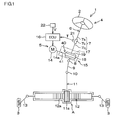
- FIG. 1 is a schematic diagram depicting a general configuration of the electric power steering system including the shaft coupling structure in the first embodiment of the invention.
- An electric power steering system 1 includes a steering mechanism 4 and a steering operation mechanism A to steer steered wheels 3 based on a driver's operation of a steering wheel 2 (steering member).
- the steering mechanism 4 includes an assist mechanism 5 that assists the driver's steering operation.
- the steering mechanism 4 includes a steering shaft 6.
- the steering shaft 6 includes a column shaft 7, an intermediate shaft 9, and a pinion shaft 11.
- the column shaft 7 has an input shaft 7a, an output shaft 7b, and a torsion bar 7c.
- the input shaft 7a is coupled to the steering wheel 2 (steering member).
- the output shaft 7b is coupled to the input shaft 7a via the torsion bar 7c.
- the intermediate shaft 9 is coupled via a universal joint 8 to the pinion shaft 11, which has a pinion 11a.
- the steering operation mechanism A has a rack shaft 12 and tie rods 13.
- the rack shaft 12 has a rack 12a meshed with the pinion 11a.
- Each of the tie rods 13 is coupled to the rack shaft 12 at its one end and to the corresponding steered wheel 3 at the other end.
- the pinion shaft 11 rotates via the input shaft 7a, the output shaft 7b, and the intermediate shaft 9. Rotation of the pinion shaft 11 is converted into reciprocating motion of the rack shaft 12 in an axial direction by the steering operation mechanism A.
- the reciprocating motion of the rack shaft 12 in the axial direction varies the steered angle of the steered wheels 3.
- the assist mechanism 5 has a torque sensor 21, an electronic control unit (ECU) 16, an electric motor 14, a power transmission joint 41, and a worm reduction gear 15.
- the torque sensor 21 detects the amount of torsion between the input shaft 7a and the output shaft 7b.
- the ECU 16 determines an assist torque based on a steering torque and a vehicle speed.
- the steering torque is derived from the amount of torsion detected by the torque sensor 21.
- the vehicle speed is detected by a vehicle speed sensor 22.
- the electric motor 14 is controlled by the ECU 16 to be driven.
- the power transmission joint 41 couples a rotating shaft 14a (first shaft) of the electric motor 14 to a worm shaft 18 (second shaft) that is an input shaft of the worm reduction gear 15.
- a shaft coupling structure 40 in the present embodiment includes the rotating shaft 14a that is the first shaft, the worm shaft 18 that is the second shaft, and the power transmission joint 41. Rotation output from the electric motor 14 is transmitted to the worm reduction gear 15 via the power transmission joint 41.
- the worm reduction gear 15 transmits a rotational force of the electric motor 14 to the output shaft 7b. As a result, the assist torque is applied to the output shaft 7b to assist the driver's steering operation.
- FIG. 2 is a sectional view of an important part of the electric power steering system 1 including the shaft coupling structure 40 in the first embodiment of the invention.
- the worm reduction gear 15 has a housing 17, a worm shaft 18, a first bearing 23, a second bearing 24, a worm wheel 19, and a biasing portion 90.
- the worm shaft 18, the first bearing 23, the second bearing 24, the worm wheel 19, and the biasing portion 90 are housed in the housing 17.
- the worm shaft 18 has a first end 18a and a second end 18b separated from each other in the axial direction and a tooth portion 18c that is an intermediate portion between the first end 18a and the second end 18b.
- the worm shaft 18 is housed in a housing portion 17a of the housing 17.
- the worm shaft 18 (second shaft) is arranged coaxially with the rotating shaft 14a of the electric motor 14 (first shaft).
- the first end 18a of the worm shaft 18 faces an end 14b of the rotating shaft 14a of the electric motor 14 in the axial direction X.
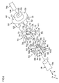
- FIG. 3 is an exploded perspective view of the shaft coupling structure 40.
- the power transmission joint 41 has a first member 50, a second member 60, and an intermediate member 70.
- the first member 50 is fixed to the end 14b of the rotating shaft 14a of the electric motor 14 so as to be rotatable integrally with the end 14b.
- the second member 60 is fixed to the first end 18a of the worm shaft 18 so as to be rotatable integrally with the first end 18a.
- the intermediate member 70 is interposed between the first member 50 and the second member 60.
- the first member 50 includes an annular main body 51 and a plurality of coupling protrusions 52.
- the first member 50 is formed of, for example, a metal material.
- the main body 51 is fixed to the rotating shaft 14a of the electric motor 14 so as to be rotatable integrally with the rotating shaft 14a.
- the main body 51 includes an annular plate 53 and a boss 54.
- the boss 54 is a tubular protrusion extending in the axial direction.
- the first member 50 has a central hole 55 that penetrates the annular plate 53 and the boss 54.
- the end 14b of the rotating shaft 14a is press-fitted in the central hole 55 in the first member 50.
- the end 14b of the rotating shaft 14a may be serration-fitted in the central hole 55 in the first member 50.
- the coupling protrusions 52 protrude from the annular plate 53 of the main body 51 toward the worm shaft 18 in the axial direction X.
- the coupling protrusions 52 are arranged at intervals in a rotating direction (corresponding to the circumferential direction Z).
- the second member 60 includes an annular main body 61 and a plurality of first radial protrusions 62.
- the main body 61 includes a resin portion 61a and a metal ring 61b.
- the resin portion 61a is annular so as to surround the first end 18a of the worm shaft 18.
- the resin portion 61a is formed integrally with the first radial protrusions 62.
- the metal ring 61b is attached to the resin portion 61a by insert molding.
- the metal ring 61b defines a fitting hole 61c for the first end 18a of the worm shaft 18.
- the first end 18a of the worm shaft 18 is press-fitted into the fitting hole 61c in the metal ring 61b.
- the first end 18a of the worm shaft 18 may be serration-fitted into the fitting hole 61c.
- the first radial protrusions 62 extend radially outward from the main body 61 and are spaced from one another at regular intervals in the rotating direction (circumferential direction Z).
- First cutouts 63 are each formed between the corresponding two first radial protrusions 62 adjacent to each other in the rotating direction (circumferential direction Z), such that the coupling protrusions 52 are each inserted through the corresponding first cutout 63.
- the first radial protrusions 62 are formed of resin integrally with the resin portion 61a of the main body 61.
- Each of the first radial protrusions 62 includes a first surface 62a that is a surface facing the intermediate member 70.
- the first surface 62a is provided with a protruding portion 64 that is a first protruding or recessed portion that protrudes or is recessed in the axial direction X.
- the protruding portion 64 (first protruding or recessed portion) protrudes from the first surface 62a toward the intermediate member 70 in the axial direction X.
- the protruding portion 64 is arranged in a central portion of the first surface 62a in the rotating direction (circumferential direction Z).
- the intermediate member 70 includes an annular main body 71, a plurality of second radial protrusions 72, and an axially biasing portion 73.
- the intermediate member 70 is formed of an elastic member, for example, rubber or resin.
- the resin of the second member 60 (the resin portion 61a of the main body 61 and the first radial protrusions 62
- the second radial protrusions 72 extend radially outward from the main body 71 and are spaced from one another at regular intervals in the rotating direction (circumferential direction Z).
- Second cutouts 74 are each formed between corresponding two radial protrusions 72 adjacent to each other in the rotating direction (circumferential direction Z), such that the coupling protrusions 52 are each inserted through the corresponding second cutout 74.
- Each of the second cutouts 74 is smaller than each of the first cutouts 63 in width in the circumferential direction Z.
- Each of the second radial protrusions 72 includes a second surface 72a that is a surface facing the corresponding first radial protrusion 62.
- the second surface 72a is provided with a recessed portion 75 that is a second protruding or recessed portion recessed in the axial direction X.
- the protruding portions 64 (first protruding or recessed portions) of the first radial protrusions 62 engage with the respective recessed portions 75 (second protruding or recessed portions) of the second radial protrusions 72 in the axial direction X (see FIG. 5A that is a sectional view of the shaft coupling structure 40 in the circumferential direction Z). Consequently, the protruding portions 64 and the recessed portions 75 can rotate integrally with one another in the rotating direction.
- the axially biasing portion 73 is a columnar member. A part of the axially biasing portion 73 is arranged concentrically with a central hole 71 a in the main body 71. This part of the axially biasing portion 73 and an inner surface of the central hole 71a are coupled together via a plurality of arm-like coupling protrusions 76 extending radially in the radial direction. The remaining part of the axially biasing portion 73 protrudes from the central hole 71a toward the rotating shaft 14a and is fitted into the central hole 55 in the first member 50.
- FIG. 4 is a sectional view of an important part of the shaft coupling structure 40 in a direction perpendicular to the axial direction.
- FIG. 5A, FIG. 5B, and FIG. 5C are sectional views of the shaft coupling structure 40 in the circumferential direction Z.
- FIG. 4 illustrates a non-steering state (a state where no torque is transmitted through the rotating shaft 14a).
- FIG. 5A illustrates a state where a torque lower than a predetermined torque is transmitted through the rotating shaft 14a.
- FIG. 5B and FIG. 5C illustrate a state where a torque equal to or higher than the predetermined torque is transmitted through the rotating shaft 14a and where a relative rotation angle between the first member 50 and the second member 60 is equal to a predetermined angle ⁇ 1 (see FIG. 4 ).
- the predetermined angle ⁇ 1 is a rotation angle in a first rotating direction R1 or a second rotating direction R2 with reference to a rotational position of the first member 50 with respect to the second member 60 in the non-steering state.
- Each of the second radial protrusions 72 is larger than each of the first radial protrusions 62 in the width in the circumferential direction Z.
- the intermediate member 70 is formed of an elastic member.
- the second member 60 is configured to be able to swing in the first rotating direction R1 and the second rotating direction R2 (circumferential direction Z) with respect to the first member 50 while the relative rotation angle between the first member 50 and the second member 60 is smaller than the predetermined angle ⁇ 1. That is, while the relative rotation angle between the first member 50 and the second member 60 is smaller than the predetermined angle ⁇ 1, the worm shaft 18 is elastically coupled to the rotating shaft 14a of the electric motor 14 so as to be able to swing with respect to the rotating shaft 14a.
- the torque transmitted through the rotating shaft 14a is transmitted to the worm shaft 18 via the coupling protrusions 52 of the first member 50 and the first radial protrusions 62 of the second member 60.
- Torque equal to or higher than the predetermined torque is not loaded on the intermediate member 70 that is formed of the elastic member. Therefore, in the intermediate member 70, durability deterioration such as wear of the ends 721 and 722 can be restrained.
- the worm wheel 19 has a core portion 19a and a tooth portion 19b.
- the core portion 19a is formed of, for example, a metal material and is annularly shaped.
- the core portion 19a is fitted over an outer periphery of the output shaft 7b so as to rotate integrally with the output shaft 7b.
- the tooth portion 19b is formed of, for example, a resin material and is annularly shaped.
- the invention is not limited to the electric power steering system of a column assist type in the present embodiment, in which the torque of the electric motor 14 is applied to the output shaft 7b, located on an upstream side of the pinion shaft 11.
- the invention may adopt the electric power steering system of a pinion assist type, in which the torque of the electric motor 14 is applied to the pinion shaft 11. In this case, the worm wheel 19 is fixed to the pinion shaft 11.
- the tooth portion 19b is fitted over an outer periphery of the core portion 19a so as to rotate integrally with the core portion 19a.
- Teeth 19c are formed on an outer peripheral surface of the tooth portion 19b so as to mesh with teeth of the tooth portion 18c of the worm shaft 18.
- the first bearing 23 is, for example, a rolling bearing.
- the first bearing 23 has an inner ring 25, an outer ring 27, and a plurality of rolling elements.
- the inner ring 25 is fitted over an outer periphery of the first end 18a of the worm shaft 18 so as to rotate integrally with the worm shaft 18.
- the inner ring 25 is sandwiched, in the axial direction X, between a snap ring 39 fitted in an outer peripheral groove in the worm shaft 18 and a positioning step portion 33a on an outer periphery of the worm shaft 18.
- the outer ring 27 is fitted in a bearing hole 26 formed in the housing 17.
- the outer ring 27 is sandwiched, in the axial direction, between a positioning step portion 28 at an end of the bearing hole 26 and a locking member 29 screw-threaded in the bearing hole 26.
- the first bearing 23 has an internal clearance.
- the intermediate member 70 of the shaft coupling structure 40 is formed of an elastic member, and a small clearance is set between each of the rolling elements and each of the inner ring 25 and the outer ring 27.
- the worm shaft 18 is supported so as to be able to swing with respect to the housing 17 using a center B of the first bearing 23 as a support.
- the biasing portion 90 has a bearing holder 35 on which a spring seat portion 35b is provided and a compression coil spring 36 serving as a biasing member.
- the bearing holder 35 includes a main body 35a fitted over the outer ring 31 of the second bearing 24 to hold the outer ring 31.
- the spring seat portion 35b protrudes from the main body 35a axially outward X2 of the worm shaft 18 (toward a side opposite from the rotating shaft 14a).
- the compression coil spring 36 is arranged axially outward X2 of the worm shaft 18.
- the compression coil spring 36 is interposed between a spring seat portion 37 formed in the housing 17 and the spring seat portion 35b of the bearing holder 35. To make the worm shaft 18 closer to the worm wheel 19, the compression coil spring 36 biases the second end 18b of the worm shaft 18 toward the worm wheel 19 via the spring seat portion 35b and the second bearing 24 with respect to the housing 17 using the center B of the first bearing 23 as a support.
- the holding hole 32 in the housing 17 holds the second bearing 24 via the bearing holder 35.
- the bearing holder 35 and the compression coil spring 36 are housed in the holding hole 32 along with the second end 18b of the worm shaft 18 and the second bearing 24.
- An axially outward end of the holding hole 32 is closed with a cover member 38.
- the holding hole 32 is formed as a biasing hole to hold the bearing holder 35 so that the second end 18b of the worm shaft 18 is movable in a first direction Y1 and a second direction Y2.
- the first direction Y1 is a direction in which a center-to-center distance D1 between the worm shaft 18 and the worm wheel 19 increases.
- the second direction Y2 is a direction in which the center-to-center distance D1 between the worm shaft 18 and the worm wheel 19 decreases.
- the second direction Y2 corresponds to a biasing direction in which the compression coil spring 36 biases the spring seat portion 37.
- the first direction corresponds to a direction opposite to the biasing direction of the compression coil spring 36.
- the bearing holder 35 may be omitted from the biasing portion 90, and the spring seat portion 35b may be integrated with the outer ring 31.
- the outer ring 31 of the second bearing 24 is held directly by the holding hole 32.
- the coupling protrusions 52 of the first member 50 come into abutting contact with the respective first radial protrusions 62 of the second member 60. This suppresses compressive deformation of the ends 721 and 722 of the second radial protrusions 72 of the intermediate member 70 in the circumferential direction Z.
- the first member 50, the second member 60, and the intermediate member 70 formed of the elastic member can form the shaft coupling structure 40. This enables a reduction in the number of components of the shaft coupling structure 40 while maintaining a function to restrain the elastic member (intermediate member 70) from being worn away.
- the second shaft (worm shaft 18) is spline-fitted in the fitting hole 61c in the second member 60. This enables a reduction in the axial length of a fitting portion between the second shaft (worm shaft 18) and the fitting hole 61c. Consequently, the shaft coupling structure 40 can be downsized in the axial direction X.
- the biasing portion 90 can be easily provided with an arrangement space for the compression coil spring 36 that is arranged axially outward X2 of the worm shaft 18.
- the second member 60 contains resin, restraining a possible rattle between the first member 50 and the second member 60. Specifically, a possible rattle is restrained between the coupling protrusions 52 of the first member 50 and the first radial protrusions 62 of the second member 60.
- the second shaft (worm shaft 18) is fitted into the metal ring 61b attached to the resin portion 61a of the second member 60 by insert molding. Thus, the coupling strength between the second shaft (worm shaft 18) and the second member 60 is enhanced.
- FIG. 6 is a schematic sectional view of an important part of a shaft coupling structure 40P in a second embodiment of the invention.
- the shaft coupling structure 40P in the second embodiment of the invention is different from the shaft coupling structure 40 in the first embodiment in FIG. 5A mainly as follows. That is, in a power transmission joint 41P of the shaft coupling structure 40, a second member 60P and an intermediate member 70P are molded together by two-shot molding.
- the second member 60P is formed of a resin harder than the resin of the intermediate member 70P.
- Protruding portions 64P (first protruding or recessed portions) of first radial protrusions 62P of the second member 60P are each formed to have a trapezoidal sectional shape such that the width of the protruding portion 64P in the circumferential direction Z increases toward a tip of the protruding portion 64P.
- Recessed portions 75P (second protruding or recessed portions) of second radial protrusions 72P of the intermediate member 70P are formed to have a sectional shape conforming to the sectional shape of the protruding portion 64.
- FIG. 7 is a schematic sectional view of an important part of a shaft coupling structure 40Q in a third embodiment of the invention.
- the shaft coupling structure 40Q in the third embodiment in FIG. 7 is different from the shaft coupling structure 40 in the first embodiment in FIG. 5A mainly as follows.
- recessed portions 64Q that are first protruding or recessed portions are formed in respective first radial protrusions 62Q of a second member 60Q.
- Protruding portions 75Q that are second protruding or recessed portions are provided on respective second radial protrusions 72Q of an intermediate member 70Q.
- the recessed portions 64Q engage with the respective protruding portions 75Q in the axial direction.
- FIG. 8 is a schematic sectional view depicting a joining structure that is included in a shaft coupling structure 40R in a fourth embodiment of the invention and in which a second member 60R of a power transmission joint 41R is joined to the worm shaft 18.
- the shaft coupling structure 40R in the fourth embodiment in FIG. 8 is different from the shaft coupling structure 40 in the first embodiment in FIG. 5A mainly in that the metal ring 61b is omitted from the shaft coupling structure 40R and that the second member 60R is formed only of resin.
- the worm shaft 18 is press-fitted in the fitting hole 61c in a main body 61R of the second member 60R (for example, the worm shaft 18 is serration-fitted in the fitting hole 61c).
- FIG. 9 is an exploded perspective view of a shaft coupling structure 40S in a fifth embodiment in the invention in which an axially biasing member 73S is disassembled from an intermediate member 70S of a power transmission joint 41S.
- the shaft coupling structure 40S in the fifth embodiment in FIG. 9 is different from the shaft coupling structure 40 in the first embodiment in FIG. 3 mainly in that the shaft coupling structure 40S includes the columnar axially biasing member 73S formed separately from the intermediate member 70S.
- Components of the fifth embodiment in FIG. 9 that are the same as the corresponding components of the first embodiment in FIG. 5A are denoted by the same reference numerals as those of the components of the first embodiment in FIG. 5A .
- the present embodiment enables a reduction in the number of components.
- the intermediate member 70S and the axially biasing member 73S may be formed of respective materials suitable for the functions thereof. This increases the degree of freedom of material selection.
- the first member may be coupled to the worm shaft, and the second member may be coupled to the rotating shaft.
- the shaft coupling structure may be applied to a power transmission system other than the electric power steering system.
- Various other changes may be made to the invention within the scope of the claims.
Landscapes
- Engineering & Computer Science (AREA)
- Mechanical Engineering (AREA)
- General Engineering & Computer Science (AREA)
- Chemical & Material Sciences (AREA)
- Combustion & Propulsion (AREA)
- Transportation (AREA)
- Power Steering Mechanism (AREA)
- Gear Transmission (AREA)
Abstract
A shaft coupling structure includes a rotating shaft (14), a worm shaft (18), a first member (50), a second member (60), and an intermediate member (70) that is an elastic member. The intermediate member is interposed between the first member and the second member. Coupling protrusions (52) of the first member that extend in an axial direction are each inserted between second radial protrusions of the intermediate member and between a plurality of first radial protrusions of the second member. Protruding portions of the first radial protrusions engage with the corresponding recessed portions of the second radial protrusions in the axial direction. When a relative rotation angle between the first member and the second member is smaller than a predetermined angle, ends of each of the second radial protrusions in a circumferential direction each projects in the circumferential direction with respect to a corresponding end of the corresponding first radial protrusion in the circumferential direction.
Description
- The invention relates to a shaft coupling mechanism and an electric power steering system.
- In general, in an electric power steering system, an assist torque is applied to a steering shaft by transmitting output rotation of an electric motor to an input gear of a reduction gear and transmitting rotation of an output gear of the reduction gear to the steering shaft. A rotating shaft of the electric motor and the input gear (for example, a worm shaft) of the reduction gear are coupled together via a shaft coupling structure. Japanese Patent Application Publication No.
2006-183676 JP 2006-183676 A - During torque transmission, when protruding portions of the interposition member is compressively deformed by a given amount or more, corresponding side surfaces of protruding portions of the rotation transmitting members come into contact with each other. Consequently, the protruding portions of the interposition member are restrained from being further compressively deformed, and thus, the protruding portions of the interposition member (elastic member) is restrained from being worn away.
- However, in
JP 2006-183676 A - An object of the invention is to provide a shaft coupling structure and an electric power steering system that enable a reduction in the number of components while maintaining a function to restrain an elastic member from being worn away.
- In an aspect of the invention, a shaft coupling structure includes a first shaft and a second shaft that face each other in an axial direction to transmit a rotational force acting in a circumferential direction, a first member that includes a plurality of coupling protrusions extending toward the second shaft in the axial direction and spaced from one another in the circumferential direction and that is coupled to the first shaft, a second member including a plurality of first radial protrusions extending radially and each having a first surface that faces the first shaft and on which a first protruding or recessed portion protruding or recessed in the axial direction is formed, the coupling protrusions each inserted between the corresponding first radial protrusions, the second member coupled to the second shaft, and an intermediate member including a plurality of second radial protrusions extending radially and having a second surface that faces the second shaft and on which a second protruding or recessed portion protruding or recessed in the axial direction is formed such that a recess or protrusion of the second protruding or recessed portion engage with a protrusion or recess, respectively, of the corresponding first protruding or recessed portion in the axial direction, the coupling protrusions each inserted between the corresponding second radial protrusions, the intermediate member being an elastic member interposed between the first member and the second member , wherein
when a relative rotation angle between the first member and the second member is smaller than a predetermined angle, a pair of ends of each of the second radial protrusions in the circumferential direction each projects in the circumferential direction with respect to a corresponding end of a corresponding first radial protrusion in the circumferential direction. - The foregoing and further features and advantages of the invention will become apparent from the following description of example embodiments with reference to the accompanying drawings, wherein like numerals are used to represent like elements and wherein:
-
FIG. 1 is a schematic diagram depicting a general configuration of an electric power steering system including a shaft coupling structure in a first embodiment of the invention; -
FIG. 2 is a sectional view of an important part of the electric power steering system in the first embodiment; -
FIG. 3 is an exploded perspective view of a shaft coupling structure in the first embodiment; -
FIG. 4 is a sectional view of the shaft coupling structure in the first embodiment in a direction perpendicular to an axial direction; -
FIG. 5A is a sectional view of an important part of the shaft coupling structure in a circumferential direction in a state where a relative rotation angle between a first member and a second member is smaller than a predetermined angle in the first embodiment; -
FIG. 5B is a sectional view of an important part of the shaft coupling structure in the circumferential direction in a state where a torque is transmitted in a first rotating direction and where the relative rotation angle between the first member and the second member is equal to the predetermined angle in the first embodiment; -
FIG. 5C is a sectional view of an important part of the shaft coupling structure in the circumferential direction in a state where a torque is transmitted in a second rotating direction and where the relative rotation angle between the first member and the second member is equal to the predetermined angle in the first embodiment; -
FIG. 6 is a sectional view of an important part of a shaft coupling structure in the circumferential direction in a second embodiment of the invention; -
FIG. 7 is a sectional view of an important part of a shaft coupling structure in the circumferential direction in a third embodiment of the invention; -
FIG. 8 is a schematic sectional view of a joining structure that is included in a shaft coupling structure in a fourth embodiment of the invention and in which the second member and a worm shaft are jointed together; and -
FIG. 9 is an exploded perspective view of an intermediate member and an axial biasing member in a shaft coupling structure in a fifth embodiment of the invention - An electric power steering system including a shaft coupling structure in a first embodiment of the invention will be described in brief using
FIG. 1. FIG. 1 is a schematic diagram depicting a general configuration of the electric power steering system including the shaft coupling structure in the first embodiment of the invention. An electricpower steering system 1 includes asteering mechanism 4 and a steering operation mechanism A to steer steeredwheels 3 based on a driver's operation of a steering wheel 2 (steering member). Thesteering mechanism 4 includes anassist mechanism 5 that assists the driver's steering operation. - The
steering mechanism 4 includes asteering shaft 6. Thesteering shaft 6 includes a column shaft 7, anintermediate shaft 9, and apinion shaft 11. The column shaft 7 has aninput shaft 7a, anoutput shaft 7b, and a torsion bar 7c. Theinput shaft 7a is coupled to the steering wheel 2 (steering member). Theoutput shaft 7b is coupled to theinput shaft 7a via the torsion bar 7c. Theintermediate shaft 9 is coupled via a universal joint 8 to thepinion shaft 11, which has apinion 11a. - The steering operation mechanism A has a
rack shaft 12 andtie rods 13. Therack shaft 12 has arack 12a meshed with thepinion 11a. Each of thetie rods 13 is coupled to therack shaft 12 at its one end and to the corresponding steeredwheel 3 at the other end. When thesteering wheel 2 rotates in accordance with the driver's operation of thesteering wheel 2, thepinion shaft 11 rotates via theinput shaft 7a, theoutput shaft 7b, and theintermediate shaft 9. Rotation of thepinion shaft 11 is converted into reciprocating motion of therack shaft 12 in an axial direction by the steering operation mechanism A. The reciprocating motion of therack shaft 12 in the axial direction varies the steered angle of the steeredwheels 3. - The
assist mechanism 5 has atorque sensor 21, an electronic control unit (ECU) 16, anelectric motor 14, apower transmission joint 41, and aworm reduction gear 15. Thetorque sensor 21 detects the amount of torsion between theinput shaft 7a and theoutput shaft 7b. The ECU 16 determines an assist torque based on a steering torque and a vehicle speed. The steering torque is derived from the amount of torsion detected by thetorque sensor 21. The vehicle speed is detected by avehicle speed sensor 22. Theelectric motor 14 is controlled by the ECU 16 to be driven. - The
power transmission joint 41 couples a rotatingshaft 14a (first shaft) of theelectric motor 14 to a worm shaft 18 (second shaft) that is an input shaft of theworm reduction gear 15. Ashaft coupling structure 40 in the present embodiment includes the rotatingshaft 14a that is the first shaft, theworm shaft 18 that is the second shaft, and thepower transmission joint 41. Rotation output from theelectric motor 14 is transmitted to theworm reduction gear 15 via thepower transmission joint 41. Theworm reduction gear 15 transmits a rotational force of theelectric motor 14 to theoutput shaft 7b. As a result, the assist torque is applied to theoutput shaft 7b to assist the driver's steering operation. - The
shaft coupling structure 40 according to the first embodiment of the invention and a peripheral structure thereof will be described usingFIG. 2. FIG. 2 is a sectional view of an important part of the electricpower steering system 1 including theshaft coupling structure 40 in the first embodiment of the invention. As depicted inFIG. 2 , theworm reduction gear 15 has ahousing 17, aworm shaft 18, a first bearing 23, a second bearing 24, aworm wheel 19, and abiasing portion 90. Theworm shaft 18, thefirst bearing 23, thesecond bearing 24, theworm wheel 19, and the biasingportion 90 are housed in thehousing 17. - The
worm shaft 18 has afirst end 18a and asecond end 18b separated from each other in the axial direction and atooth portion 18c that is an intermediate portion between thefirst end 18a and thesecond end 18b. Theworm shaft 18 is housed in ahousing portion 17a of thehousing 17. The worm shaft 18 (second shaft) is arranged coaxially with therotating shaft 14a of the electric motor 14 (first shaft). Thefirst end 18a of theworm shaft 18 faces anend 14b of therotating shaft 14a of theelectric motor 14 in the axial direction X. - In the
shaft coupling structure 40, theend 14b of therotating shaft 14a of theelectric motor 14 is coupled to thefirst end 18a of theworm shaft 18 via the power transmission joint 41 so as to be able to transmit torque to and from thefirst end 18a. Theshaft coupling structure 40 has a function to transmit rotation of therotating shaft 14a in a circumferential direction Z to theworm shaft 18.FIG. 3 is an exploded perspective view of theshaft coupling structure 40. - As depicted in
FIG. 2 andFIG. 3 , in theshaft coupling structure 40, the power transmission joint 41 has afirst member 50, asecond member 60, and anintermediate member 70. Thefirst member 50 is fixed to theend 14b of therotating shaft 14a of theelectric motor 14 so as to be rotatable integrally with theend 14b. Thesecond member 60 is fixed to thefirst end 18a of theworm shaft 18 so as to be rotatable integrally with thefirst end 18a. Theintermediate member 70 is interposed between thefirst member 50 and thesecond member 60. - The
first member 50 includes an annularmain body 51 and a plurality ofcoupling protrusions 52. Thefirst member 50 is formed of, for example, a metal material. Themain body 51 is fixed to therotating shaft 14a of theelectric motor 14 so as to be rotatable integrally with therotating shaft 14a. Themain body 51 includes anannular plate 53 and aboss 54. Theboss 54 is a tubular protrusion extending in the axial direction. Thefirst member 50 has acentral hole 55 that penetrates theannular plate 53 and theboss 54. Theend 14b of therotating shaft 14a is press-fitted in thecentral hole 55 in thefirst member 50. For example, theend 14b of therotating shaft 14a may be serration-fitted in thecentral hole 55 in thefirst member 50. - As depicted in
FIG. 3 , thecoupling protrusions 52 protrude from theannular plate 53 of themain body 51 toward theworm shaft 18 in the axial direction X. The coupling protrusions 52 are arranged at intervals in a rotating direction (corresponding to the circumferential direction Z). As depicted inFIG. 2 andFIG. 3 , thesecond member 60 includes an annularmain body 61 and a plurality of firstradial protrusions 62. - The
main body 61 includes aresin portion 61a and ametal ring 61b. Theresin portion 61a is annular so as to surround thefirst end 18a of theworm shaft 18. Theresin portion 61a is formed integrally with the firstradial protrusions 62. Themetal ring 61b is attached to theresin portion 61a by insert molding. Themetal ring 61b defines afitting hole 61c for thefirst end 18a of theworm shaft 18. - The
first end 18a of theworm shaft 18 is press-fitted into thefitting hole 61c in themetal ring 61b. For example, thefirst end 18a of theworm shaft 18 may be serration-fitted into thefitting hole 61c. As depicted inFIG. 3 , the firstradial protrusions 62 extend radially outward from themain body 61 and are spaced from one another at regular intervals in the rotating direction (circumferential direction Z).First cutouts 63 are each formed between the corresponding two firstradial protrusions 62 adjacent to each other in the rotating direction (circumferential direction Z), such that thecoupling protrusions 52 are each inserted through the correspondingfirst cutout 63. The firstradial protrusions 62 are formed of resin integrally with theresin portion 61a of themain body 61. - Each of the first
radial protrusions 62 includes afirst surface 62a that is a surface facing theintermediate member 70. Thefirst surface 62a is provided with a protrudingportion 64 that is a first protruding or recessed portion that protrudes or is recessed in the axial direction X. The protruding portion 64 (first protruding or recessed portion) protrudes from thefirst surface 62a toward theintermediate member 70 in the axial direction X. The protrudingportion 64 is arranged in a central portion of thefirst surface 62a in the rotating direction (circumferential direction Z). Theintermediate member 70 includes an annularmain body 71, a plurality of secondradial protrusions 72, and anaxially biasing portion 73. Theintermediate member 70 is formed of an elastic member, for example, rubber or resin. The resin of the second member 60 (theresin portion 61a of themain body 61 and the first radial protrusions 62) is harder than the resin of theintermediate member 70. - The second
radial protrusions 72 extend radially outward from themain body 71 and are spaced from one another at regular intervals in the rotating direction (circumferential direction Z).Second cutouts 74 are each formed between corresponding tworadial protrusions 72 adjacent to each other in the rotating direction (circumferential direction Z), such that thecoupling protrusions 52 are each inserted through the correspondingsecond cutout 74. Each of thesecond cutouts 74 is smaller than each of thefirst cutouts 63 in width in the circumferential direction Z. - Each of the second
radial protrusions 72 includes asecond surface 72a that is a surface facing the corresponding firstradial protrusion 62. Thesecond surface 72a is provided with a recessedportion 75 that is a second protruding or recessed portion recessed in the axial direction X. The protruding portions 64 (first protruding or recessed portions) of the firstradial protrusions 62 engage with the respective recessed portions 75 (second protruding or recessed portions) of the secondradial protrusions 72 in the axial direction X (seeFIG. 5A that is a sectional view of theshaft coupling structure 40 in the circumferential direction Z). Consequently, the protrudingportions 64 and the recessedportions 75 can rotate integrally with one another in the rotating direction. - As depicted in
FIG. 2 andFIG. 3 , theaxially biasing portion 73 is a columnar member. A part of theaxially biasing portion 73 is arranged concentrically with acentral hole 71 a in themain body 71. This part of theaxially biasing portion 73 and an inner surface of thecentral hole 71a are coupled together via a plurality of arm-like coupling protrusions 76 extending radially in the radial direction. The remaining part of theaxially biasing portion 73 protrudes from thecentral hole 71a toward therotating shaft 14a and is fitted into thecentral hole 55 in thefirst member 50. - As depicted in
FIG. 2 , theaxially biasing portion 73 is elastically compressed in the axial direction X between an end surface of theend 14b of therotating shaft 14a and an end surface of thefirst end 18a of theworm shaft 18. Theaxially biasing portion 73 elastically biases theworm shaft 18 in the axial direction X.FIG. 4 is a sectional view of an important part of theshaft coupling structure 40 in a direction perpendicular to the axial direction.FIG. 5A, FIG. 5B, and FIG. 5C are sectional views of theshaft coupling structure 40 in the circumferential direction Z.FIG. 4 illustrates a non-steering state (a state where no torque is transmitted through therotating shaft 14a). -
FIG. 5A illustrates a state where a torque lower than a predetermined torque is transmitted through therotating shaft 14a.FIG. 5B and FIG. 5C illustrate a state where a torque equal to or higher than the predetermined torque is transmitted through therotating shaft 14a and where a relative rotation angle between thefirst member 50 and thesecond member 60 is equal to a predetermined angle θ1 (seeFIG. 4 ). The predetermined angle θ1 is a rotation angle in a first rotating direction R1 or a second rotating direction R2 with reference to a rotational position of thefirst member 50 with respect to thesecond member 60 in the non-steering state. - In a state where no torque is transmitted through the
rotating shaft 14a as depicted inFIG. 4 and in a state, as depicted inFIG. 5A , where a torque lower than the predetermined torque is transmitted through therotating shaft 14a and where the relative rotation angle between thefirst member 50 and thesecond member 60 is smaller than the predetermined angle θ1, a pair ofends radial protrusions 72 in the circumferential direction Z (first rotating direction R1 and second rotating direction R2) protrude from respective corresponding circumferential ends 621 and 622 of the corresponding firstradial protrusion 62 in the circumferential direction Z. - Each of the second
radial protrusions 72 is larger than each of the firstradial protrusions 62 in the width in the circumferential direction Z. Theintermediate member 70 is formed of an elastic member. Thus, thesecond member 60 is configured to be able to swing in the first rotating direction R1 and the second rotating direction R2 (circumferential direction Z) with respect to thefirst member 50 while the relative rotation angle between thefirst member 50 and thesecond member 60 is smaller than the predetermined angle θ1. That is, while the relative rotation angle between thefirst member 50 and thesecond member 60 is smaller than the predetermined angle θ1, theworm shaft 18 is elastically coupled to therotating shaft 14a of theelectric motor 14 so as to be able to swing with respect to therotating shaft 14a. - Thus, impact made when the rotating direction of the
electric motor 14 is reversed is absorbed by elastic compressive deformation of the intermediate member 70 (theends radial protrusions 72 in the circumferential direction Z) in the rotating direction. Consequently, impact made at the time of the reversal is restrained from being transmitted to thesteering wheel 2 via theworm shaft 18, theworm wheel 19, and the column shaft 7. Therefore, steering feeling is improved. - When a torque equal to or larger than the predetermined torque is transmitted through the
rotating shaft 14a of theelectric motor 14, the relative rotation angle between thefirst member 50 and thesecond member 60 is equal to the predetermined angle θ1. That is, as depicted inFIG. 5B and FIG. 5C , theend intermediate member 70 in the circumferential direction Z corresponding to the rotating direction R1 or R2 is elastically compressed. Consequently, each of thecoupling protrusions 52 of thefirst member 50 comes into abutting contact with thecorresponding end radial protrusion 62 of thesecond member 60 in the circumferential direction. - Thus, the torque transmitted through the
rotating shaft 14a is transmitted to theworm shaft 18 via thecoupling protrusions 52 of thefirst member 50 and the firstradial protrusions 62 of thesecond member 60. Torque equal to or higher than the predetermined torque is not loaded on theintermediate member 70 that is formed of the elastic member. Therefore, in theintermediate member 70, durability deterioration such as wear of theends - As seen in
FIG. 2 again, theworm wheel 19 has acore portion 19a and atooth portion 19b. Thecore portion 19a is formed of, for example, a metal material and is annularly shaped. Thecore portion 19a is fitted over an outer periphery of theoutput shaft 7b so as to rotate integrally with theoutput shaft 7b. Thetooth portion 19b is formed of, for example, a resin material and is annularly shaped. The invention is not limited to the electric power steering system of a column assist type in the present embodiment, in which the torque of theelectric motor 14 is applied to theoutput shaft 7b, located on an upstream side of thepinion shaft 11. For example, the invention may adopt the electric power steering system of a pinion assist type, in which the torque of theelectric motor 14 is applied to thepinion shaft 11. In this case, theworm wheel 19 is fixed to thepinion shaft 11. - The
tooth portion 19b is fitted over an outer periphery of thecore portion 19a so as to rotate integrally with thecore portion 19a.Teeth 19c are formed on an outer peripheral surface of thetooth portion 19b so as to mesh with teeth of thetooth portion 18c of theworm shaft 18. Thefirst bearing 23 is, for example, a rolling bearing. Thefirst bearing 23 has aninner ring 25, anouter ring 27, and a plurality of rolling elements. Theinner ring 25 is fitted over an outer periphery of thefirst end 18a of theworm shaft 18 so as to rotate integrally with theworm shaft 18. Theinner ring 25 is sandwiched, in the axial direction X, between asnap ring 39 fitted in an outer peripheral groove in theworm shaft 18 and apositioning step portion 33a on an outer periphery of theworm shaft 18. - The
outer ring 27 is fitted in abearing hole 26 formed in thehousing 17. Theouter ring 27 is sandwiched, in the axial direction, between apositioning step portion 28 at an end of the bearinghole 26 and a lockingmember 29 screw-threaded in thebearing hole 26. Thefirst bearing 23 has an internal clearance. In the present embodiment, theintermediate member 70 of theshaft coupling structure 40 is formed of an elastic member, and a small clearance is set between each of the rolling elements and each of theinner ring 25 and theouter ring 27. Thus, theworm shaft 18 is supported so as to be able to swing with respect to thehousing 17 using a center B of thefirst bearing 23 as a support. - The
axially biasing portion 73 of theshaft coupling structure 40 biases theworm shaft 18 in the axial direction X. Theaxially biasing portion 73 suppresses backlash of theworm shaft 18 in the axial direction X resulting from the internal clearance in the first bearing, to reduce rattle caused by the possible backlash. The second bearing is, for example, a rolling bearing. The second bearing has aninner ring 30, anouter ring 31, and a plurality of rolling elements. Thesecond bearing 24 is housed in a holdinghole 32 in thehousing 17. Theinner ring 30 is fitted over thesecond end 18b of theworm shaft 18 so as to rotate integrally with theworm shaft 18. One end surface of theinner ring 30 is in abutting contact with apositioning step portion 33b formed at thesecond end 18b of theworm shaft 18. - The biasing
portion 90 has abearing holder 35 on which aspring seat portion 35b is provided and acompression coil spring 36 serving as a biasing member. The bearingholder 35 includes amain body 35a fitted over theouter ring 31 of thesecond bearing 24 to hold theouter ring 31. Thespring seat portion 35b protrudes from themain body 35a axially outward X2 of the worm shaft 18 (toward a side opposite from therotating shaft 14a). - The
compression coil spring 36 is arranged axially outward X2 of theworm shaft 18. Thecompression coil spring 36 is interposed between aspring seat portion 37 formed in thehousing 17 and thespring seat portion 35b of the bearingholder 35. To make theworm shaft 18 closer to theworm wheel 19, thecompression coil spring 36 biases thesecond end 18b of theworm shaft 18 toward theworm wheel 19 via thespring seat portion 35b and thesecond bearing 24 with respect to thehousing 17 using the center B of thefirst bearing 23 as a support. - The holding
hole 32 in thehousing 17 holds thesecond bearing 24 via thebearing holder 35. The bearingholder 35 and thecompression coil spring 36 are housed in the holdinghole 32 along with thesecond end 18b of theworm shaft 18 and thesecond bearing 24. An axially outward end of the holdinghole 32 is closed with acover member 38. The holdinghole 32 is formed as a biasing hole to hold thebearing holder 35 so that thesecond end 18b of theworm shaft 18 is movable in a first direction Y1 and a second direction Y2. The first direction Y1 is a direction in which a center-to-center distance D1 between theworm shaft 18 and theworm wheel 19 increases. The second direction Y2 is a direction in which the center-to-center distance D1 between theworm shaft 18 and theworm wheel 19 decreases. The second direction Y2 corresponds to a biasing direction in which thecompression coil spring 36 biases thespring seat portion 37. The first direction corresponds to a direction opposite to the biasing direction of thecompression coil spring 36. - The bearing
holder 35 may be omitted from the biasingportion 90, and thespring seat portion 35b may be integrated with theouter ring 31. In this case, theouter ring 31 of thesecond bearing 24 is held directly by the holdinghole 32. In the present embodiment, when the relative rotation angle θ between thefirst member 50 and thesecond member 60 reaches the predetermined angle θ1, thecoupling protrusions 52 of thefirst member 50 come into abutting contact with the respective firstradial protrusions 62 of thesecond member 60. This suppresses compressive deformation of theends radial protrusions 72 of theintermediate member 70 in the circumferential direction Z. Thefirst member 50, thesecond member 60, and theintermediate member 70 formed of the elastic member can form theshaft coupling structure 40. This enables a reduction in the number of components of theshaft coupling structure 40 while maintaining a function to restrain the elastic member (intermediate member 70) from being worn away. - The second shaft (worm shaft 18) is spline-fitted in the
fitting hole 61c in thesecond member 60. This enables a reduction in the axial length of a fitting portion between the second shaft (worm shaft 18) and thefitting hole 61c. Consequently, theshaft coupling structure 40 can be downsized in the axial direction X. Thus, the biasingportion 90 can be easily provided with an arrangement space for thecompression coil spring 36 that is arranged axially outward X2 of theworm shaft 18. - The
second member 60 contains resin, restraining a possible rattle between thefirst member 50 and thesecond member 60. Specifically, a possible rattle is restrained between thecoupling protrusions 52 of thefirst member 50 and the firstradial protrusions 62 of thesecond member 60. The second shaft (worm shaft 18) is fitted into themetal ring 61b attached to theresin portion 61a of thesecond member 60 by insert molding. Thus, the coupling strength between the second shaft (worm shaft 18) and thesecond member 60 is enhanced. - The
axially biasing portion 73 integrated with theintermediate member 70 into a single member biases the second shaft (worm shaft 18) in the axial direction X. Compared to a configuration in which the axially biasing portion is provided separately from theintermediate member 70, the present configuration enables a reduction in the number of components. This enables a reduction in the number of components of the electricpower steering system 1 including theshaft coupling structure 40.FIG. 6 is a schematic sectional view of an important part of ashaft coupling structure 40P in a second embodiment of the invention. - The
shaft coupling structure 40P in the second embodiment of the invention is different from theshaft coupling structure 40 in the first embodiment inFIG. 5A mainly as follows. That is, in a power transmission joint 41P of theshaft coupling structure 40, a second member 60P and anintermediate member 70P are molded together by two-shot molding. The second member 60P is formed of a resin harder than the resin of theintermediate member 70P. Protrudingportions 64P (first protruding or recessed portions) of firstradial protrusions 62P of the second member 60P are each formed to have a trapezoidal sectional shape such that the width of the protrudingportion 64P in the circumferential direction Z increases toward a tip of the protrudingportion 64P. Recessedportions 75P (second protruding or recessed portions) of secondradial protrusions 72P of theintermediate member 70P are formed to have a sectional shape conforming to the sectional shape of the protrudingportion 64. - The protruding
portions 64P and the recessedportions 75P are joined together as in the case of wedging such that the second member 60P and theintermediate member 70P form an integral unit U. Components of the second embodiment inFIG. 6 that are the same as the corresponding components of the first embodiment inFIG. 5A are denoted by the same reference numerals as those of the components of the first embodiment inFIG. 5A . The present embodiment can produce the same effects as those of the first embodiment. Moreover, the second member 60P and theintermediate member 70P can be handled as the integral unit U. This enables a reduction in assembly man-hours needed to assemble theshaft coupling structure 40P.FIG. 7 is a schematic sectional view of an important part of ashaft coupling structure 40Q in a third embodiment of the invention. - The
shaft coupling structure 40Q in the third embodiment inFIG. 7 is different from theshaft coupling structure 40 in the first embodiment inFIG. 5A mainly as follows. In a power transmission joint 41Q of theshaft coupling structure 40Q, recessedportions 64Q that are first protruding or recessed portions are formed in respective firstradial protrusions 62Q of asecond member 60Q. Protrudingportions 75Q that are second protruding or recessed portions are provided on respective secondradial protrusions 72Q of anintermediate member 70Q. The recessedportions 64Q engage with the respective protrudingportions 75Q in the axial direction. - Components of the third embodiment in
FIG. 7 that are the same as the corresponding components of the first embodiment inFIG. 5A are denoted by the same reference numerals as those of the components of the first embodiment inFIG. 5A . The present embodiment can produce the same effects as those of the first embodiment.FIG. 8 is a schematic sectional view depicting a joining structure that is included in ashaft coupling structure 40R in a fourth embodiment of the invention and in which asecond member 60R of a power transmission joint 41R is joined to theworm shaft 18. - The
shaft coupling structure 40R in the fourth embodiment inFIG. 8 is different from theshaft coupling structure 40 in the first embodiment inFIG. 5A mainly in that themetal ring 61b is omitted from theshaft coupling structure 40R and that thesecond member 60R is formed only of resin. Theworm shaft 18 is press-fitted in thefitting hole 61c in amain body 61R of thesecond member 60R (for example, theworm shaft 18 is serration-fitted in thefitting hole 61c).FIG. 9 is an exploded perspective view of ashaft coupling structure 40S in a fifth embodiment in the invention in which anaxially biasing member 73S is disassembled from anintermediate member 70S of a power transmission joint 41S. - The
shaft coupling structure 40S in the fifth embodiment inFIG. 9 is different from theshaft coupling structure 40 in the first embodiment inFIG. 3 mainly in that theshaft coupling structure 40S includes the columnar axially biasingmember 73S formed separately from theintermediate member 70S. Components of the fifth embodiment inFIG. 9 that are the same as the corresponding components of the first embodiment inFIG. 5A are denoted by the same reference numerals as those of the components of the first embodiment inFIG. 5A . Compared to the related art, the present embodiment enables a reduction in the number of components. Theintermediate member 70S and theaxially biasing member 73S may be formed of respective materials suitable for the functions thereof. This increases the degree of freedom of material selection. - The invention is not limited to the above-described embodiments. For example, the first member may be coupled to the worm shaft, and the second member may be coupled to the rotating shaft. The shaft coupling structure may be applied to a power transmission system other than the electric power steering system. Various other changes may be made to the invention within the scope of the claims.
Claims (6)
- A shaft coupling structure comprising:a first shaft and a second shaft that face each other in an axial direction to transmit a rotational force acting in a circumferential direction;a first member that includes a plurality of coupling protrusions extending toward the second shaft in the axial direction and spaced from one another in the circumferential direction and that is coupled to the first shaft;a second member including a plurality of first radial protrusions extending radially and each having a first surface that faces the first shaft and on which a first protruding or recessed portion protruding or recessed in the axial direction is formed, the coupling protrusions each inserted between the corresponding first radial protrusions, the second member coupled to the second shaft; andan intermediate member including a plurality of second radial protrusions extending radially and having a second surface that faces the second shaft and on which a second protruding or recessed portion protruding or recessed in the axial direction is formed such that a recess or protrusion of the second protruding or recessed portion engage with a protrusion or recess, respectively, of the corresponding first protruding or recessed portion in the axial direction, the coupling protrusions each inserted between the corresponding second radial protrusions, the intermediate member being an elastic member interposed between the first member and the second member, whereinwhen a relative rotation angle between the first member and the second member is smaller than a predetermined angle, a pair of ends of each of the second radial protrusions in the circumferential direction each projects in the circumferential direction with respect to a corresponding end of a corresponding first radial protrusion in the circumferential direction.
- The shaft coupling structure according to claim 1, wherein the second member includes a fitting hole in which the second shaft is serration-fitted or spline-fitted.
- The shaft coupling structure according to claim 1 or 2, wherein the second member contains a resin harder than a resin of the intermediate member.
- The shaft coupling structure according to any one of claims 1 to 3, wherein the second member includes a resin portion and a metal ring that is attached to the resin portion by insert molding and in which the second shaft is fitted.
- The shaft coupling structure according to any one of claims 1 to 4, wherein the intermediate member includes an axially biasing portion that biases the second shaft in an axial direction.
- An electric power steering system, which includes the shaft coupling structure according to any one of claims 1 to 5, the electric power steering system comprising:an electric motor including a rotating shaft serving as the first shaft and a reduction gear including a worm shaft serving as the second shaft.
Applications Claiming Priority (1)
| Application Number | Priority Date | Filing Date | Title |
|---|---|---|---|
| JP2015157391A JP2017036767A (en) | 2015-08-07 | 2015-08-07 | Shaft coupling structure and electric power steering device |
Publications (1)
| Publication Number | Publication Date |
|---|---|
| EP3135940A1 true EP3135940A1 (en) | 2017-03-01 |
Family
ID=56842603
Family Applications (1)
| Application Number | Title | Priority Date | Filing Date |
|---|---|---|---|
| EP16181250.8A Withdrawn EP3135940A1 (en) | 2015-08-07 | 2016-07-26 | Shaft coupling structure and electric power steering system |
Country Status (4)
| Country | Link |
|---|---|
| US (1) | US20170036691A1 (en) |
| EP (1) | EP3135940A1 (en) |
| JP (1) | JP2017036767A (en) |
| CN (1) | CN106428192A (en) |
Families Citing this family (12)
| Publication number | Priority date | Publication date | Assignee | Title |
|---|---|---|---|---|
| KR101853543B1 (en) * | 2016-05-19 | 2018-04-30 | 주식회사 만도 | Reducer for vehicle |
| KR102635281B1 (en) * | 2017-02-01 | 2024-02-13 | 에이치엘만도 주식회사 | Reducer of Electric Power Steering Apparatus |
| US11518429B2 (en) * | 2017-07-25 | 2022-12-06 | Nsk, Ltd. | Torque transmission joint and electric power steering device |
| WO2019049389A1 (en) * | 2017-09-11 | 2019-03-14 | 株式会社ショーワ | Electric power steering device and shaft coupling |
| JP6393858B1 (en) * | 2018-06-12 | 2018-09-19 | 株式会社ショーワ | Rudder angle regulating device |
| JP7079689B2 (en) * | 2018-08-07 | 2022-06-02 | 日立Astemo株式会社 | Steering device |
| KR102584761B1 (en) * | 2018-09-03 | 2023-10-06 | 에이치엘만도 주식회사 | Power Transmission Device of Steering Apparatus |
| CN109455220B (en) * | 2018-11-22 | 2020-07-28 | 安徽江淮汽车集团股份有限公司 | Connecting mechanism of steering column motor and worm |
| US11448561B2 (en) * | 2019-04-05 | 2022-09-20 | Textron Innovations Inc. | Overload inhibiting torque meter |
| CN110949501B (en) * | 2019-12-17 | 2021-07-20 | 东风汽车有限公司 | Steering clutch, steering column, steering system and control method thereof |
| CN110949500B (en) * | 2019-12-17 | 2021-11-12 | 东风汽车有限公司 | Automobile and control method thereof |
| US20240209900A1 (en) * | 2021-04-22 | 2024-06-27 | Vandewiele Sweden Ab | Steering coupling and arrangement related thereto |
Citations (8)
| Publication number | Priority date | Publication date | Assignee | Title |
|---|---|---|---|---|
| US2716334A (en) * | 1951-02-20 | 1955-08-30 | Globe Flexible Coupling Compan | Flexible shaft couplings |
| DE2706034A1 (en) * | 1977-02-12 | 1978-08-17 | Herwarth Reich Nachf Dipl Ing | Shaft resilient claw type coupling - has lugs separated by resilient blocks connected at axial ends by webs |
| JPS5861332A (en) * | 1981-10-08 | 1983-04-12 | Nabeya Kogyo Kk | Flexible shaft coupling |
| JP2006183676A (en) | 2004-12-24 | 2006-07-13 | Oiles Ind Co Ltd | Shaft coupling mechanism for electric power steering device |
| EP1808618A1 (en) * | 2006-01-13 | 2007-07-18 | Jtekt Corporation | Electric power steering apparatus |
| US20120208649A1 (en) * | 2009-11-10 | 2012-08-16 | Noboru Nakagawa | Shaft coupling mechanism |
| EP2818386A1 (en) * | 2012-02-24 | 2014-12-31 | Kayaba Industry Co., Ltd. | Electric power steering device and shaft coupler used therein |
| US20150167747A1 (en) * | 2013-12-12 | 2015-06-18 | Jtekt Corporation | Shaft-to-universal joint coupling structure |
-
2015
- 2015-08-07 JP JP2015157391A patent/JP2017036767A/en active Pending
-
2016
- 2016-07-21 US US15/216,030 patent/US20170036691A1/en not_active Abandoned
- 2016-07-26 EP EP16181250.8A patent/EP3135940A1/en not_active Withdrawn
- 2016-08-05 CN CN201610638120.3A patent/CN106428192A/en active Pending
Patent Citations (8)
| Publication number | Priority date | Publication date | Assignee | Title |
|---|---|---|---|---|
| US2716334A (en) * | 1951-02-20 | 1955-08-30 | Globe Flexible Coupling Compan | Flexible shaft couplings |
| DE2706034A1 (en) * | 1977-02-12 | 1978-08-17 | Herwarth Reich Nachf Dipl Ing | Shaft resilient claw type coupling - has lugs separated by resilient blocks connected at axial ends by webs |
| JPS5861332A (en) * | 1981-10-08 | 1983-04-12 | Nabeya Kogyo Kk | Flexible shaft coupling |
| JP2006183676A (en) | 2004-12-24 | 2006-07-13 | Oiles Ind Co Ltd | Shaft coupling mechanism for electric power steering device |
| EP1808618A1 (en) * | 2006-01-13 | 2007-07-18 | Jtekt Corporation | Electric power steering apparatus |
| US20120208649A1 (en) * | 2009-11-10 | 2012-08-16 | Noboru Nakagawa | Shaft coupling mechanism |
| EP2818386A1 (en) * | 2012-02-24 | 2014-12-31 | Kayaba Industry Co., Ltd. | Electric power steering device and shaft coupler used therein |
| US20150167747A1 (en) * | 2013-12-12 | 2015-06-18 | Jtekt Corporation | Shaft-to-universal joint coupling structure |
Also Published As
| Publication number | Publication date |
|---|---|
| JP2017036767A (en) | 2017-02-16 |
| US20170036691A1 (en) | 2017-02-09 |
| CN106428192A (en) | 2017-02-22 |
Similar Documents
| Publication | Publication Date | Title |
|---|---|---|
| US20170036691A1 (en) | Shaft coupling structure and electric power steering system | |
| US9937949B2 (en) | Electric power steering system | |
| EP2450262B1 (en) | Electric power steering system | |
| US9902421B2 (en) | Worm reduction gear and steering mechanism | |
| EP2818386B1 (en) | Electric power steering device and shaft coupler used therein | |
| EP2689988B1 (en) | Electric power steering system | |
| EP3088278B1 (en) | Worm reduction gear and steering system | |
| EP1808618B1 (en) | Electric power steering apparatus | |
| CN108725572B (en) | Worm gear reducer and electric power steering device | |
| JP6164477B2 (en) | Electric power steering device | |
| US20120048640A1 (en) | Electric power steering system | |
| JP2006175891A (en) | Electric power steering device | |
| EP2966318B1 (en) | Worm speed reducer and method for manufacturing worm wheel included in worm speed reducer | |
| WO2005073054A1 (en) | Electric power steering device | |
| JP7404688B2 (en) | Worm reducer and electric assist device | |
| EP2966317A1 (en) | Worm speed reducer and electric power steering system using the same | |
| JP2012087881A (en) | Power transmission joint and electric power steering device | |
| JP2010048355A (en) | Elastic shaft coupling and electric power steering device | |
| JP2010070044A (en) | Electric power steering device | |
| JP6714845B2 (en) | Worm reducer and electric power steering device | |
| JP2016002926A (en) | Power transmission joint, worm reduction gear and electric power steering device | |
| JP2013107640A (en) | Electric power steering device | |
| JP2017210069A (en) | Shaft connecting structure and electric power steering device | |
| JP2016056953A (en) | Torque transmission joint and electric power steering device | |
| KR20170079893A (en) | Electrical Steering Apparatus and Method to manufacture the same |
Legal Events
| Date | Code | Title | Description |
|---|---|---|---|
| PUAI | Public reference made under article 153(3) epc to a published international application that has entered the european phase |
Free format text: ORIGINAL CODE: 0009012 |
|
| AK | Designated contracting states |
Kind code of ref document: A1 Designated state(s): AL AT BE BG CH CY CZ DE DK EE ES FI FR GB GR HR HU IE IS IT LI LT LU LV MC MK MT NL NO PL PT RO RS SE SI SK SM TR |
|
| AX | Request for extension of the european patent |
Extension state: BA ME |
|
| STAA | Information on the status of an ep patent application or granted ep patent |
Free format text: STATUS: THE APPLICATION IS DEEMED TO BE WITHDRAWN |
|
| 18D | Application deemed to be withdrawn |
Effective date: 20170902 |