EP3135934A1 - Bearing having a shim between two ring parts - Google Patents
Bearing having a shim between two ring parts Download PDFInfo
- Publication number
- EP3135934A1 EP3135934A1 EP15306310.2A EP15306310A EP3135934A1 EP 3135934 A1 EP3135934 A1 EP 3135934A1 EP 15306310 A EP15306310 A EP 15306310A EP 3135934 A1 EP3135934 A1 EP 3135934A1
- Authority
- EP
- European Patent Office
- Prior art keywords
- annular
- ring parts
- nicks
- shim
- annular ring
- Prior art date
- Legal status (The legal status is an assumption and is not a legal conclusion. Google has not performed a legal analysis and makes no representation as to the accuracy of the status listed.)
- Granted
Links
Images



Classifications
-
- F—MECHANICAL ENGINEERING; LIGHTING; HEATING; WEAPONS; BLASTING
- F16—ENGINEERING ELEMENTS AND UNITS; GENERAL MEASURES FOR PRODUCING AND MAINTAINING EFFECTIVE FUNCTIONING OF MACHINES OR INSTALLATIONS; THERMAL INSULATION IN GENERAL
- F16C—SHAFTS; FLEXIBLE SHAFTS; ELEMENTS OR CRANKSHAFT MECHANISMS; ROTARY BODIES OTHER THAN GEARING ELEMENTS; BEARINGS
- F16C23/00—Bearings for exclusively rotary movement adjustable for aligning or positioning
- F16C23/06—Ball or roller bearings
-
- F—MECHANICAL ENGINEERING; LIGHTING; HEATING; WEAPONS; BLASTING
- F16—ENGINEERING ELEMENTS AND UNITS; GENERAL MEASURES FOR PRODUCING AND MAINTAINING EFFECTIVE FUNCTIONING OF MACHINES OR INSTALLATIONS; THERMAL INSULATION IN GENERAL
- F16C—SHAFTS; FLEXIBLE SHAFTS; ELEMENTS OR CRANKSHAFT MECHANISMS; ROTARY BODIES OTHER THAN GEARING ELEMENTS; BEARINGS
- F16C23/00—Bearings for exclusively rotary movement adjustable for aligning or positioning
- F16C23/06—Ball or roller bearings
- F16C23/08—Ball or roller bearings self-adjusting
-
- F—MECHANICAL ENGINEERING; LIGHTING; HEATING; WEAPONS; BLASTING
- F16—ENGINEERING ELEMENTS AND UNITS; GENERAL MEASURES FOR PRODUCING AND MAINTAINING EFFECTIVE FUNCTIONING OF MACHINES OR INSTALLATIONS; THERMAL INSULATION IN GENERAL
- F16C—SHAFTS; FLEXIBLE SHAFTS; ELEMENTS OR CRANKSHAFT MECHANISMS; ROTARY BODIES OTHER THAN GEARING ELEMENTS; BEARINGS
- F16C25/00—Bearings for exclusively rotary movement adjustable for wear or play
- F16C25/06—Ball or roller bearings
-
- F—MECHANICAL ENGINEERING; LIGHTING; HEATING; WEAPONS; BLASTING
- F16—ENGINEERING ELEMENTS AND UNITS; GENERAL MEASURES FOR PRODUCING AND MAINTAINING EFFECTIVE FUNCTIONING OF MACHINES OR INSTALLATIONS; THERMAL INSULATION IN GENERAL
- F16C—SHAFTS; FLEXIBLE SHAFTS; ELEMENTS OR CRANKSHAFT MECHANISMS; ROTARY BODIES OTHER THAN GEARING ELEMENTS; BEARINGS
- F16C33/00—Parts of bearings; Special methods for making bearings or parts thereof
- F16C33/30—Parts of ball or roller bearings
- F16C33/58—Raceways; Race rings
- F16C33/583—Details of specific parts of races
-
- F—MECHANICAL ENGINEERING; LIGHTING; HEATING; WEAPONS; BLASTING
- F16—ENGINEERING ELEMENTS AND UNITS; GENERAL MEASURES FOR PRODUCING AND MAINTAINING EFFECTIVE FUNCTIONING OF MACHINES OR INSTALLATIONS; THERMAL INSULATION IN GENERAL
- F16C—SHAFTS; FLEXIBLE SHAFTS; ELEMENTS OR CRANKSHAFT MECHANISMS; ROTARY BODIES OTHER THAN GEARING ELEMENTS; BEARINGS
- F16C11/00—Pivots; Pivotal connections
- F16C11/04—Pivotal connections
- F16C11/06—Ball-joints; Other joints having more than one degree of angular freedom, i.e. universal joints
-
- F—MECHANICAL ENGINEERING; LIGHTING; HEATING; WEAPONS; BLASTING
- F16—ENGINEERING ELEMENTS AND UNITS; GENERAL MEASURES FOR PRODUCING AND MAINTAINING EFFECTIVE FUNCTIONING OF MACHINES OR INSTALLATIONS; THERMAL INSULATION IN GENERAL
- F16C—SHAFTS; FLEXIBLE SHAFTS; ELEMENTS OR CRANKSHAFT MECHANISMS; ROTARY BODIES OTHER THAN GEARING ELEMENTS; BEARINGS
- F16C19/00—Bearings with rolling contact, for exclusively rotary movement
- F16C19/02—Bearings with rolling contact, for exclusively rotary movement with bearing balls essentially of the same size in one or more circular rows
- F16C19/14—Bearings with rolling contact, for exclusively rotary movement with bearing balls essentially of the same size in one or more circular rows for both radial and axial load
-
- F—MECHANICAL ENGINEERING; LIGHTING; HEATING; WEAPONS; BLASTING
- F16—ENGINEERING ELEMENTS AND UNITS; GENERAL MEASURES FOR PRODUCING AND MAINTAINING EFFECTIVE FUNCTIONING OF MACHINES OR INSTALLATIONS; THERMAL INSULATION IN GENERAL
- F16C—SHAFTS; FLEXIBLE SHAFTS; ELEMENTS OR CRANKSHAFT MECHANISMS; ROTARY BODIES OTHER THAN GEARING ELEMENTS; BEARINGS
- F16C19/00—Bearings with rolling contact, for exclusively rotary movement
- F16C19/22—Bearings with rolling contact, for exclusively rotary movement with bearing rollers essentially of the same size in one or more circular rows, e.g. needle bearings
- F16C19/34—Bearings with rolling contact, for exclusively rotary movement with bearing rollers essentially of the same size in one or more circular rows, e.g. needle bearings for both radial and axial load
-
- F—MECHANICAL ENGINEERING; LIGHTING; HEATING; WEAPONS; BLASTING
- F16—ENGINEERING ELEMENTS AND UNITS; GENERAL MEASURES FOR PRODUCING AND MAINTAINING EFFECTIVE FUNCTIONING OF MACHINES OR INSTALLATIONS; THERMAL INSULATION IN GENERAL
- F16C—SHAFTS; FLEXIBLE SHAFTS; ELEMENTS OR CRANKSHAFT MECHANISMS; ROTARY BODIES OTHER THAN GEARING ELEMENTS; BEARINGS
- F16C33/00—Parts of bearings; Special methods for making bearings or parts thereof
- F16C33/30—Parts of ball or roller bearings
- F16C33/58—Raceways; Race rings
- F16C33/60—Raceways; Race rings divided or split, e.g. comprising two juxtaposed rings
-
- F—MECHANICAL ENGINEERING; LIGHTING; HEATING; WEAPONS; BLASTING
- F16—ENGINEERING ELEMENTS AND UNITS; GENERAL MEASURES FOR PRODUCING AND MAINTAINING EFFECTIVE FUNCTIONING OF MACHINES OR INSTALLATIONS; THERMAL INSULATION IN GENERAL
- F16C—SHAFTS; FLEXIBLE SHAFTS; ELEMENTS OR CRANKSHAFT MECHANISMS; ROTARY BODIES OTHER THAN GEARING ELEMENTS; BEARINGS
- F16C19/00—Bearings with rolling contact, for exclusively rotary movement
- F16C19/22—Bearings with rolling contact, for exclusively rotary movement with bearing rollers essentially of the same size in one or more circular rows, e.g. needle bearings
- F16C19/34—Bearings with rolling contact, for exclusively rotary movement with bearing rollers essentially of the same size in one or more circular rows, e.g. needle bearings for both radial and axial load
- F16C19/36—Bearings with rolling contact, for exclusively rotary movement with bearing rollers essentially of the same size in one or more circular rows, e.g. needle bearings for both radial and axial load with a single row of rollers
- F16C19/361—Bearings with rolling contact, for exclusively rotary movement with bearing rollers essentially of the same size in one or more circular rows, e.g. needle bearings for both radial and axial load with a single row of rollers with cylindrical rollers
- F16C19/362—Bearings with rolling contact, for exclusively rotary movement with bearing rollers essentially of the same size in one or more circular rows, e.g. needle bearings for both radial and axial load with a single row of rollers with cylindrical rollers the rollers being crossed within the single row
-
- F—MECHANICAL ENGINEERING; LIGHTING; HEATING; WEAPONS; BLASTING
- F16—ENGINEERING ELEMENTS AND UNITS; GENERAL MEASURES FOR PRODUCING AND MAINTAINING EFFECTIVE FUNCTIONING OF MACHINES OR INSTALLATIONS; THERMAL INSULATION IN GENERAL
- F16C—SHAFTS; FLEXIBLE SHAFTS; ELEMENTS OR CRANKSHAFT MECHANISMS; ROTARY BODIES OTHER THAN GEARING ELEMENTS; BEARINGS
- F16C2226/00—Joining parts; Fastening; Assembling or mounting parts
- F16C2226/50—Positive connections
- F16C2226/60—Positive connections with threaded parts, e.g. bolt and nut connections
-
- F—MECHANICAL ENGINEERING; LIGHTING; HEATING; WEAPONS; BLASTING
- F16—ENGINEERING ELEMENTS AND UNITS; GENERAL MEASURES FOR PRODUCING AND MAINTAINING EFFECTIVE FUNCTIONING OF MACHINES OR INSTALLATIONS; THERMAL INSULATION IN GENERAL
- F16C—SHAFTS; FLEXIBLE SHAFTS; ELEMENTS OR CRANKSHAFT MECHANISMS; ROTARY BODIES OTHER THAN GEARING ELEMENTS; BEARINGS
- F16C2240/00—Specified values or numerical ranges of parameters; Relations between them
- F16C2240/30—Angles, e.g. inclinations
-
- F—MECHANICAL ENGINEERING; LIGHTING; HEATING; WEAPONS; BLASTING
- F16—ENGINEERING ELEMENTS AND UNITS; GENERAL MEASURES FOR PRODUCING AND MAINTAINING EFFECTIVE FUNCTIONING OF MACHINES OR INSTALLATIONS; THERMAL INSULATION IN GENERAL
- F16C—SHAFTS; FLEXIBLE SHAFTS; ELEMENTS OR CRANKSHAFT MECHANISMS; ROTARY BODIES OTHER THAN GEARING ELEMENTS; BEARINGS
- F16C2300/00—Application independent of particular apparatuses
- F16C2300/10—Application independent of particular apparatuses related to size
- F16C2300/14—Large applications, e.g. bearings having an inner diameter exceeding 500 mm
-
- F—MECHANICAL ENGINEERING; LIGHTING; HEATING; WEAPONS; BLASTING
- F16—ENGINEERING ELEMENTS AND UNITS; GENERAL MEASURES FOR PRODUCING AND MAINTAINING EFFECTIVE FUNCTIONING OF MACHINES OR INSTALLATIONS; THERMAL INSULATION IN GENERAL
- F16C—SHAFTS; FLEXIBLE SHAFTS; ELEMENTS OR CRANKSHAFT MECHANISMS; ROTARY BODIES OTHER THAN GEARING ELEMENTS; BEARINGS
- F16C33/00—Parts of bearings; Special methods for making bearings or parts thereof
- F16C33/30—Parts of ball or roller bearings
- F16C33/58—Raceways; Race rings
- F16C33/60—Raceways; Race rings divided or split, e.g. comprising two juxtaposed rings
- F16C33/61—Raceways; Race rings divided or split, e.g. comprising two juxtaposed rings formed by wires
Definitions
- the present invention relates to the field of bearings, such as bearings including rows of rolling elements, such as rollers or balls, inserted between rings.
- one of the rings comprises two annular ring parts cooperating with the row of rolling elements, there is difficulties to position correctly these parts axially one relative to the other, easily and without induce undesired stress on the rolling elements.
- the present invention aims to resolve these difficulties.
- a bearing comprising at least two rings able to pivot relative to one another, at least one of said rings comprising at least two annular ring parts having annular radial surfaces axially opposite each other, the bearing comprising further : at least one annular shim interposed between said radial surfaces of said annular ring parts and comprising successive circumferential portions, each circumferential portion of said shim having a plurality of nicks respectively traversed by axial elements, the nicks of each circumferential portion of said annular shim being shaped and oriented to permit the positioning between the annular ring parts and the removal of each circumferential portion by radial translation.
- the annular shim is substantially continuous all along the circumference and is positioned correctly.
- At least some of the axial elements can be carried by at least one of said annular ring parts and form abutments cooperating with the circumferential portions in said nicks thereof in order to position the circumferential portions relative to said annular ring parts.
- At least some of the axial elements can be formed by screws securing said annular ring parts together.
- At least some of the axial elements can be formed by screws securing said annular ring parts to a frame.
- At least some of the nicks of each circumferential portion of the annular shim can have a bottom and opposite sides parallel to the direction of said translation.
- the nicks of each circumferential portion can be opened from the outside to the inside.
- the nicks of each circumferential portion can be opened from the inside to the outside.
- the circumferential portions can have identical shapes.
- the annular shim can comprise more than two circumferential portions extending respectively along angles lower than 180°.
- the annular shim can comprise two circumferential portions extending respectively along an angle of 180°.
- a bearing 1 comprises an outer ring 2 and an inner ring 3 which are concentric and rotatable about an axis (not shown).
- a row 4 of rolling elements 5, such as rollers, is interposed between the outer ring 2 and the inner ring 3, the rolling elements 5 being circumferentially spaced apart by means of a cage 6.
- the outer ring 2 is made of one-piece and the inner ring 3 comprises two annular ring parts 7 and 8 which are axially adjacent.
- the annular ring parts 7 and 8 are provided with adjacent cylindrical surfaces 9 and 10 for maintaining these parts radially one relative to the other and for permitting axial motion one relative to the other.
- the annular ring parts 7 and 8 are provided with annular radial surfaces 11 and 12 which are axially opposite each other, these surfaces extending from ends of the cylindrical surfaces toward the inside.
- An annular radial shim 13 is interposed between the radial surfaces 11 and 12 of the annular ring parts.
- the thickness of the annular shim 13 determines the axial positions of the annular ring parts 7 and 8 one relative to the other.
- Two annular wires 14 and 15 are secured to the outer ring 2 and determine two outer raceways 16 and 17 which are axially spaced apart.
- Two annular wires 18 and 19 are secured respectively to the annular ring parts 7 and 8 of the inner ring 2 and determine two inner raceways 20 and 21 which are axially spaced apart.
- the row 4 of rolling elements 5 is placed in the space determined by the outer raceways 16 and 17 and the inner raceways 20 and 21, on which the rolling elements 5 are in contact and guided circumferentially.
- the outer ring 2 and the annular ring parts 7 and 8 of the inner ring 3 can be made of aluminum or an aluminum alloy
- the annular wires 14, 15, 16 and 17 can be made of a steel
- the radial shim 13 can be made of a steel.
- the annular radial shim 13 is divided or segmented circumferentially and comprises successive circumferential portions 22 which extend along angular sectors and are formed as local radial sheets.
- the circumferential portions 22 can be obtained by laser cutting of a sheet.
- the annular radial shim 13 comprises more than two circumferential portions 22, which are preferably identical.
- the annular ring parts 7 and 8 are provided with a plurality of positioning axial pins 24 which are spaced apart circumferentially and introduced in axial holes 24a and 24b of the annular ring parts 7 and 8.
- the positioning axial pins 24 traverse the annular radial shim 13. More specifically, two axial pins 24 traverse two positioning nicks 25 provided through each circumferential portion 22, at a short distance from the ends of this portion 22.
- annular ring parts 7 and 8 are secured one on the other by means of axial screws 26 which are spaced apart circumferentially and which traverse the annular radial shim 13. More specifically, the screws 26 traverse nicks 27 provided through the circumferential portions 22.
- the positioning pins 24 and the axial screws 26 are disposed on the same circumference.
- each circumferential portion 22 The nicks 25 and 27 of each circumferential portion 22 are opened towards the outside and are shaped and oriented to permit, when the annular ring parts 7 and 8 are axially away, the positioning between the annular ring parts 7 and 8 and the removal of each circumferential portion 22 by radial translations along a radial direction 28 passing through the middle of each circumferential portion 22.
- each circumferential portion 22 are oblong and have respectively bottoms 29 and 30 and opposite sides 31, 32 and 33, 34 which are parallel to the corresponding direction 28.
- each circumferential portion 22 can be placed by radial translation along the corresponding radial direction 28 from the inside towards the outside such that the corresponding positioning pins 24 enter in the nicks 25 and that the circumferential portion 22 is guided by the corresponding pins 24 between the sides 31 and 32 of the corresponding positioning nicks 25, until the bottoms 29 of the positioning nicks 25 abut the positioning pins 24 laterally.
- the shafts of the screws 26 enter in the nicks 27 and moved towards the bottoms 30 of the nicks 27, freely and with a clearance.
- the bearing 1 is in operating condition.
- the inner ring 3 is mounted on an annular frame 35 by means of axial screws 36 spaced apart circumferentially and disposed on the same circumference than the axial pins 24 and the axial screws 26.
- the shaft of the screws 36 traverse the annular ring part 8 and are secured to the annular ring part.
- the shafts of the screws 36 traverse, freely and with a clearance, holes 37 of the circumferential portions 22 of the annular radial shim 13. Nevertheless, the holes 37 could be also nicks opened.
- the outer ring 2 is mounted on an annular frame 38 by means of axial screws 39.
- a bearing 40 is different from the bearing 1 by the fact that it comprises an outer ring 41 comprising two annular ring parts 42 and 43 which are axially adjacent and a one-piece inner ring 44.
- the annular ring parts 42 and 43 and the one-piece inner ring 44 are equipped with annular wires inverted relative to the bearing 1 and defining raceways for a row of rolling elements.
- annular ring parts 42 and 43 have opposite annular radial surfaces 45 and 46 extending from adjacent cylindrical surfaces 47 and 48 towards the outside.
- a segmented annular radial shim 49 is inserted between the annular radial surfaces 45 and 46 and comprises successive circumferential portions 50.
- segmented annular radial shim 49 comprises two circumferential portions 50 which extend respectively along an angle of 180° and which are preferably identical. Nevertheless, the segmented annular radial shim 49 could comprise more than two circumferential portions 50.
- each circumferential portion 50 is provided with nicks 51 and 52 which corresponds to the nicks 25 and 27 but which are opened towards the inside.
- each circumferential portion 50 can be moved from the outside towards the inside along a radial direction in order to be positioned between the annular ring parts 42 and 43 such that the nicks 51 and 52 receive laterally positioning pins 53 and shafts of screws 54 connecting the annular ring parts 42 and 43 and equivalent to the pins 24 and the screw 26 of the bearing 1.
- Each circumferential portion 50 can be moved from the inside towards the outside along this radial direction in order to be removed.
- the circumferential portions constituting the annular radial shims cooperate with at least two elements formed by positioning axial pins inserted in nicks thereof, the circumferential portions occupy determined positions radially and circumferentially with respect to the annular ring parts constituting the outer ring or the inner ring of the bearing.
- annular radial shims extend substantially all along a circumference, there is no gap between the annular parts constituting the rings and axial deformations of these parts one relative to the other under the effect of the fixing screws are avoided and inappropriate stress on the row of rolling elements are avoided.
- the bearings comprise one row of rolling elements.
- the present invention can be applied to bearings having several rows of rolling elements.
- the invention can also applied to bearings which have no rolling element, such as dry sliding bearings.
Landscapes
- Engineering & Computer Science (AREA)
- General Engineering & Computer Science (AREA)
- Mechanical Engineering (AREA)
- Rolling Contact Bearings (AREA)
- Mounting Of Bearings Or Others (AREA)
Description
- The present invention relates to the field of bearings, such as bearings including rows of rolling elements, such as rollers or balls, inserted between rings.
- When one of the rings comprises two annular ring parts cooperating with the row of rolling elements, there is difficulties to position correctly these parts axially one relative to the other, easily and without induce undesired stress on the rolling elements.
- The present invention aims to resolve these difficulties.
- According to one embodiment, it is proposed a bearing comprising at least two rings able to pivot relative to one another, at least one of said rings comprising at least two annular ring parts having annular radial surfaces axially opposite each other, the bearing comprising further : at least one annular shim interposed between said radial surfaces of said annular ring parts and comprising successive circumferential portions, each circumferential portion of said shim having a plurality of nicks respectively traversed by axial elements, the nicks of each circumferential portion of said annular shim being shaped and oriented to permit the positioning between the annular ring parts and the removal of each circumferential portion by radial translation.
- So, the annular shim is substantially continuous all along the circumference and is positioned correctly.
- At least some of the axial elements can be carried by at least one of said annular ring parts and form abutments cooperating with the circumferential portions in said nicks thereof in order to position the circumferential portions relative to said annular ring parts.
- At least some of the axial elements can be formed by screws securing said annular ring parts together.
- At least some of the axial elements can be formed by screws securing said annular ring parts to a frame.
- At least some of the nicks of each circumferential portion of the annular shim can have a bottom and opposite sides parallel to the direction of said translation.
- The nicks of each circumferential portion can be opened from the outside to the inside.
- The nicks of each circumferential portion can be opened from the inside to the outside.
- The circumferential portions can have identical shapes.
- The annular shim can comprise more than two circumferential portions extending respectively along angles lower than 180°.
- The annular shim can comprise two circumferential portions extending respectively along an angle of 180°.
- Bearings according to the present invention will now be described as examples and illustrated on the drawing in which:
-
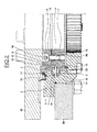
Figure 1 is a local radial section of a bearing; -
Figure 2 is another radial section of the bearing offigure 1 ; -
Figure 3 is another radial section of the bearing offigure 1 ; -
Figure 4 is a local top view of a shim of the bearing offigure 1 ; -
Figure 5 is a local radial section of another bearing; and -
Figure 6 is an exploded top view of the bearing offigure 5 . - As illustrated in
figures 1 to 3 , according to an embodiment, abearing 1 comprises anouter ring 2 and aninner ring 3 which are concentric and rotatable about an axis (not shown). - For supporting and transmitting radial and axial loads, a row 4 of
rolling elements 5, such as rollers, is interposed between theouter ring 2 and theinner ring 3, therolling elements 5 being circumferentially spaced apart by means of acage 6. - The
outer ring 2 is made of one-piece and theinner ring 3 comprises twoannular ring parts - The
annular ring parts cylindrical surfaces - The
annular ring parts radial surfaces - An annular
radial shim 13 is interposed between theradial surfaces annular shim 13 determines the axial positions of theannular ring parts - Two
annular wires outer ring 2 and determine twoouter raceways - Two
annular wires annular ring parts inner ring 2 and determine twoinner raceways - The row 4 of
rolling elements 5 is placed in the space determined by theouter raceways inner raceways rolling elements 5 are in contact and guided circumferentially. - As an example, the
outer ring 2 and theannular ring parts inner ring 3 can be made of aluminum or an aluminum alloy, theannular wires radial shim 13 can be made of a steel. - As illustrated on
figure 4 , the annularradial shim 13 is divided or segmented circumferentially and comprises successivecircumferential portions 22 which extend along angular sectors and are formed as local radial sheets. Thecircumferential portions 22 can be obtained by laser cutting of a sheet. - In this embodiment, the annular
radial shim 13 comprises more than twocircumferential portions 22, which are preferably identical. - As illustrated on
figures 1 and4 , theannular ring parts axial pins 24 which are spaced apart circumferentially and introduced inaxial holes annular ring parts - The positioning
axial pins 24 traverse the annularradial shim 13. More specifically, twoaxial pins 24 traverse twopositioning nicks 25 provided through eachcircumferential portion 22, at a short distance from the ends of thisportion 22. - As illustrated on
figures 2 and4 , theannular ring parts axial screws 26 which are spaced apart circumferentially and which traverse the annularradial shim 13. More specifically, thescrews 26traverse nicks 27 provided through thecircumferential portions 22. - The positioning pins 24 and the
axial screws 26 are disposed on the same circumference. - The
nicks circumferential portion 22 are opened towards the outside and are shaped and oriented to permit, when theannular ring parts annular ring parts circumferential portion 22 by radial translations along aradial direction 28 passing through the middle of eachcircumferential portion 22. - More particularly, the
nicks circumferential portion 22 are oblong and have respectivelybottoms opposite sides corresponding direction 28. - So, when the
annular ring parts circumferential portion 22 can be placed by radial translation along the correspondingradial direction 28 from the inside towards the outside such that the corresponding positioning pins 24 enter in thenicks 25 and that thecircumferential portion 22 is guided by the corresponding pins 24 between thesides corresponding positioning nicks 25, until thebottoms 29 of thepositioning nicks 25 abut the positioning pins 24 laterally. At the same time, the shafts of thescrews 26 enter in thenicks 27 and moved towards thebottoms 30 of thenicks 27, freely and with a clearance. - When all the
circumferential portions 22 are positioned or in place, thescrews 26 are blocked in order to compress the annularradial shim 13 between theradial surfaces annular ring parts annular ring parts - The
bearing 1 is in operating condition. - If the annular
radial shim 13 has to be removed, after unblocking of thescrews 26, thecircumferential portions 22 are moved by radial translations from the outside to the inside along the correspondingdirections 28. Newcircumferential portions 22 having another thickness can be positioned as above described. - As illustrated on
figures 3 and4 , thebearing 1 being assembly, theinner ring 3 is mounted on anannular frame 35 by means ofaxial screws 36 spaced apart circumferentially and disposed on the same circumference than theaxial pins 24 and the axial screws 26. - The shaft of the
screws 36 traverse theannular ring part 8 and are secured to the annular ring part. The shafts of thescrews 36 traverse, freely and with a clearance, holes 37 of thecircumferential portions 22 of the annularradial shim 13. Nevertheless, theholes 37 could be also nicks opened. Moreover, theouter ring 2 is mounted on anannular frame 38 by means ofaxial screws 39. - As illustrated in
figures 5 and6 , according to another embodiment, abearing 40 is different from thebearing 1 by the fact that it comprises anouter ring 41 comprising twoannular ring parts inner ring 44. Theannular ring parts inner ring 44 are equipped with annular wires inverted relative to thebearing 1 and defining raceways for a row of rolling elements. - In this embodiment, the
annular ring parts cylindrical surfaces - A segmented annular
radial shim 49 is inserted between the annular radial surfaces 45 and 46 and comprises successivecircumferential portions 50. - In this embodiment, the segmented annular
radial shim 49 comprises twocircumferential portions 50 which extend respectively along an angle of 180° and which are preferably identical. Nevertheless, the segmented annularradial shim 49 could comprise more than twocircumferential portions 50. - In this embodiment, each
circumferential portion 50 is provided withnicks nicks - When the
annular ring parts circumferential portion 50 can be moved from the outside towards the inside along a radial direction in order to be positioned between theannular ring parts nicks pins 53 and shafts ofscrews 54 connecting theannular ring parts pins 24 and thescrew 26 of thebearing 1. - Each
circumferential portion 50 can be moved from the inside towards the outside along this radial direction in order to be removed. - The described bearings have the following advantages.
- As the circumferential portions constituting the annular radial shims cooperate with at least two elements formed by positioning axial pins inserted in nicks thereof, the circumferential portions occupy determined positions radially and circumferentially with respect to the annular ring parts constituting the outer ring or the inner ring of the bearing.
- The positioning and the removal of the circumferential portions constituting the annular radial shims can be executed easily and quickly.
- As the annular radial shims extend substantially all along a circumference, there is no gap between the annular parts constituting the rings and axial deformations of these parts one relative to the other under the effect of the fixing screws are avoided and inappropriate stress on the row of rolling elements are avoided.
- In this description, the bearings comprise one row of rolling elements. Nevertheless, the present invention can be applied to bearings having several rows of rolling elements. The invention can also applied to bearings which have no rolling element, such as dry sliding bearings.
Claims (10)
- Bearing comprising at least two rings able to pivot relative to one another, at least one of said rings comprising at least two annular ring parts (7, 8) having annular radial surfaces (11, 12) axially opposite each other, the bearing comprising further:at least one annular shim (13) interposed between said radial surfaces of said annular ring parts and comprising successive circumferential portions (22),each circumferential portion of said shim having a plurality of nicks (25) respectively traversed by axial elements (24),the nicks of each circumferential portion of said annular shim being shaped and oriented to permit the positioning between the annular ring parts and the removal of each circumferential portion by radial translation.
- Bearing according to claim 1, in which at least some of the axial elements (24) are carried by at least one of said annular ring parts and form abutments cooperating with the circumferential portions in said nicks thereof in order to position the circumferential portions relative to said annular ring parts.
- Bearing according to claims 1 and 2, in which at least some of the axial elements are formed by screws (26) securing said annular ring parts together.
- Bearing according to anyone of the preceding claims, in which at least some of the axial elements are formed by screws (36) securing said annular ring parts to a frame.
- Bearing according to anyone of the preceding claims, in which at least some of the nicks of each circumferential portion of the annular shim have a bottom (29) and opposite sides (31, 32) parallel to the direction of said translation.
- Bearing according to anyone of the preceding claims, in which the nicks of each circumferential portion are opened from the outside to the inside.
- Bearing according to anyone of the preceding claims 1 to 5, in which the nicks of each circumferential portion are opened from the inside to the outside.
- Bearing according to anyone of the preceding claims, in which the circumferential portions have identical shapes.
- Bearing according to anyone of the preceding claims, in which the annular shim comprises more than two circumferential portions extending respectively along angles lower than 180°.
- Bearing according to anyone of the preceding claims, in which the annular shim comprises two circumferential portions extending respectively along an angle of 180°.
Priority Applications (4)
| Application Number | Priority Date | Filing Date | Title |
|---|---|---|---|
| EP15306310.2A EP3135934B1 (en) | 2015-08-25 | 2015-08-25 | Bearing having a shim between two ring parts |
| KR1020160104017A KR102631572B1 (en) | 2015-08-25 | 2016-08-17 | Bearing having a shim between two ring parts |
| US15/244,667 US10041533B2 (en) | 2015-08-25 | 2016-08-23 | Bearing having a shim between two ring parts |
| CN201610719541.9A CN106481665B (en) | 2015-08-25 | 2016-08-24 | Bearings with spacers between two ring parts |
Applications Claiming Priority (1)
| Application Number | Priority Date | Filing Date | Title |
|---|---|---|---|
| EP15306310.2A EP3135934B1 (en) | 2015-08-25 | 2015-08-25 | Bearing having a shim between two ring parts |
Publications (2)
| Publication Number | Publication Date |
|---|---|
| EP3135934A1 true EP3135934A1 (en) | 2017-03-01 |
| EP3135934B1 EP3135934B1 (en) | 2019-07-31 |
Family
ID=54007656
Family Applications (1)
| Application Number | Title | Priority Date | Filing Date |
|---|---|---|---|
| EP15306310.2A Active EP3135934B1 (en) | 2015-08-25 | 2015-08-25 | Bearing having a shim between two ring parts |
Country Status (4)
| Country | Link |
|---|---|
| US (1) | US10041533B2 (en) |
| EP (1) | EP3135934B1 (en) |
| KR (1) | KR102631572B1 (en) |
| CN (1) | CN106481665B (en) |
Families Citing this family (1)
| Publication number | Priority date | Publication date | Assignee | Title |
|---|---|---|---|---|
| CN110242675B (en) * | 2019-07-01 | 2024-06-07 | 洛阳新强联回转支承股份有限公司 | Assembly method of oversized double-row tapered roller slewing bearing |
Citations (4)
| Publication number | Priority date | Publication date | Assignee | Title |
|---|---|---|---|---|
| US3802755A (en) * | 1973-04-25 | 1974-04-09 | Hoesch Ag | Two-row antifriction bearing |
| GB1392641A (en) * | 1972-06-29 | 1975-04-30 | Wireglide Bearings Ltd | Rotational bearings |
| DD133988A1 (en) * | 1977-11-24 | 1979-01-31 | Manfred Behnke | WIRE BALL BEARINGS FOR UHV TECHNOLOGY |
| DE102008004070A1 (en) * | 2008-01-12 | 2009-07-16 | Franke & Heydrich Kg | Method for adjusting bearing play and/or bearing pre-stress with e.g. grooved ball bearing, involves increasing or decreasing running paths diameter of rolling bodies by radial displacement of races over prismatic flanks of bearing slots |
Family Cites Families (16)
| Publication number | Priority date | Publication date | Assignee | Title |
|---|---|---|---|---|
| GB800428A (en) * | 1955-06-16 | 1958-08-27 | Priestman Brothers | Improvements relating to slewing bearings for cranes and the like |
| GB1453327A (en) * | 1974-02-04 | 1976-10-20 | Priestman Bros Ltd | Roller bearings |
| US4196947A (en) * | 1978-02-22 | 1980-04-08 | Clark Equipment Company | Adjustable four point contact bearing |
| US4400042A (en) * | 1980-10-14 | 1983-08-23 | Keystone Engineering Company | High performance low torque anti-friction bearing assembly |
| US5125756A (en) * | 1989-12-26 | 1992-06-30 | Lucas Western, Inc. | Roller bearing with load-reacted cage |
| DE4007881A1 (en) * | 1990-03-13 | 1991-09-19 | Skf Gmbh | Mounting assembly for shaft |
| FR2660975B1 (en) * | 1990-04-13 | 1992-06-19 | Roulements Soc Nouvelle | ROLLING BODY BEARING EQUIPPED WITH AN ORIENTABLE INFORMATION SENSOR DEVICE. |
| US5129156A (en) * | 1990-12-20 | 1992-07-14 | General Electric Company | Method for setting the axial end play of tapered roller bearings |
| GB2358892B (en) * | 2000-02-05 | 2004-06-09 | Federal Mogul Rpb Ltd | Tilting pad bearing arrangement |
| US6865809B2 (en) * | 2003-04-08 | 2005-03-15 | General Motors Corporation | Method of preloading tapered roller bearings |
| US7594760B2 (en) * | 2003-09-15 | 2009-09-29 | Pratt & Whitney Rocketdyne, Inc. | Bearing cup rotational lock assembly |
| CN201496398U (en) * | 2009-09-30 | 2010-06-02 | 马鞍山方圆回转支承股份有限公司 | Three-point contact steel wire roller path type pivoting support used for ship unloader |
| US8353633B2 (en) * | 2010-01-15 | 2013-01-15 | Dresser-Rand Company | Bearing assembly support and adjustment system |
| JP5789524B2 (en) * | 2012-01-17 | 2015-10-07 | 日立建機株式会社 | Bearing equipment for construction machinery |
| JP6481382B2 (en) * | 2015-01-26 | 2019-03-13 | コベルコ建機株式会社 | Electric motor |
| JP2017180687A (en) * | 2016-03-30 | 2017-10-05 | 株式会社 神崎高級工機製作所 | Rolling bearing-type transmission mechanism |
-
2015
- 2015-08-25 EP EP15306310.2A patent/EP3135934B1/en active Active
-
2016
- 2016-08-17 KR KR1020160104017A patent/KR102631572B1/en active Active
- 2016-08-23 US US15/244,667 patent/US10041533B2/en active Active
- 2016-08-24 CN CN201610719541.9A patent/CN106481665B/en active Active
Patent Citations (4)
| Publication number | Priority date | Publication date | Assignee | Title |
|---|---|---|---|---|
| GB1392641A (en) * | 1972-06-29 | 1975-04-30 | Wireglide Bearings Ltd | Rotational bearings |
| US3802755A (en) * | 1973-04-25 | 1974-04-09 | Hoesch Ag | Two-row antifriction bearing |
| DD133988A1 (en) * | 1977-11-24 | 1979-01-31 | Manfred Behnke | WIRE BALL BEARINGS FOR UHV TECHNOLOGY |
| DE102008004070A1 (en) * | 2008-01-12 | 2009-07-16 | Franke & Heydrich Kg | Method for adjusting bearing play and/or bearing pre-stress with e.g. grooved ball bearing, involves increasing or decreasing running paths diameter of rolling bodies by radial displacement of races over prismatic flanks of bearing slots |
Also Published As
| Publication number | Publication date |
|---|---|
| CN106481665B (en) | 2020-12-15 |
| EP3135934B1 (en) | 2019-07-31 |
| KR20170024539A (en) | 2017-03-07 |
| US20170058949A1 (en) | 2017-03-02 |
| KR102631572B1 (en) | 2024-01-30 |
| CN106481665A (en) | 2017-03-08 |
| US10041533B2 (en) | 2018-08-07 |
Similar Documents
| Publication | Publication Date | Title |
|---|---|---|
| US10724577B2 (en) | Split bearing cartridge assembly and split housed bearing assembly | |
| EP2966310B1 (en) | Roller bearing cage | |
| US9695869B2 (en) | Spherical plain bearing with inner sleeve | |
| US20140003755A1 (en) | Bearing device having a safety bearing | |
| CN106369060B (en) | Segmented cages for bearings | |
| US10690181B2 (en) | Angular contact roller bearing and method and device for the assembly thereof | |
| US7093981B2 (en) | Self-aligning bearing | |
| US20170138404A1 (en) | Rolling bearing | |
| EP2955405B1 (en) | Rolling bearing with means for angularly adjusting of the inner ring relative to the outer ring | |
| US9388851B1 (en) | Split cylindrical roller bearing | |
| US9541129B2 (en) | Rolling bearing guide ring | |
| EP3135934B1 (en) | Bearing having a shim between two ring parts | |
| KR20140116822A (en) | Rolling bearing comprising at least one multi-part ring, notably for a wind turbine, and associated mounting method | |
| US10514063B2 (en) | Rolling bearing | |
| EP3109495A1 (en) | Roller bearing cage | |
| US20160298688A1 (en) | Spherical roller bearing arrangement | |
| US10570960B2 (en) | Segmented cage for rolling bearing | |
| US1622065A (en) | Thrust ball bearing | |
| CN104454981B (en) | A kind of heavy trunnion of converter subdivision self-aligning roller bearing | |
| US11767881B2 (en) | Rolling-element bearing, notably large-diameter rolling-element bearing | |
| JP6602459B2 (en) | Double row cylindrical roller bearing | |
| JP2013053716A (en) | Self-aligning roller bearing and turning wheel support structure | |
| EP3548760B1 (en) | Bearing assembly and bearing cage | |
| JP2026074702A (en) | Angular contact ball bearing and method for manufacturing the same | |
| CN111059152A (en) | bearing ring |
Legal Events
| Date | Code | Title | Description |
|---|---|---|---|
| PUAI | Public reference made under article 153(3) epc to a published international application that has entered the european phase |
Free format text: ORIGINAL CODE: 0009012 |
|
| STAA | Information on the status of an ep patent application or granted ep patent |
Free format text: STATUS: THE APPLICATION HAS BEEN PUBLISHED |
|
| AK | Designated contracting states |
Kind code of ref document: A1 Designated state(s): AL AT BE BG CH CY CZ DE DK EE ES FI FR GB GR HR HU IE IS IT LI LT LU LV MC MK MT NL NO PL PT RO RS SE SI SK SM TR |
|
| AX | Request for extension of the european patent |
Extension state: BA ME |
|
| STAA | Information on the status of an ep patent application or granted ep patent |
Free format text: STATUS: REQUEST FOR EXAMINATION WAS MADE |
|
| 17P | Request for examination filed |
Effective date: 20170830 |
|
| STAA | Information on the status of an ep patent application or granted ep patent |
Free format text: STATUS: EXAMINATION IS IN PROGRESS |
|
| 17Q | First examination report despatched |
Effective date: 20180905 |
|
| REG | Reference to a national code |
Ref country code: DE Ref legal event code: R079 Ref document number: 602015034719 Country of ref document: DE Free format text: PREVIOUS MAIN CLASS: F16C0033610000 Ipc: F16C0033600000 |
|
| RIC1 | Information provided on ipc code assigned before grant |
Ipc: F16C 25/06 20060101ALI20190117BHEP Ipc: F16C 33/61 20060101ALN20190117BHEP Ipc: F16C 19/36 20060101ALN20190117BHEP Ipc: F16C 33/60 20060101AFI20190117BHEP |
|
| GRAP | Despatch of communication of intention to grant a patent |
Free format text: ORIGINAL CODE: EPIDOSNIGR1 |
|
| STAA | Information on the status of an ep patent application or granted ep patent |
Free format text: STATUS: GRANT OF PATENT IS INTENDED |
|
| INTG | Intention to grant announced |
Effective date: 20190222 |
|
| GRAS | Grant fee paid |
Free format text: ORIGINAL CODE: EPIDOSNIGR3 |
|
| GRAA | (expected) grant |
Free format text: ORIGINAL CODE: 0009210 |
|
| STAA | Information on the status of an ep patent application or granted ep patent |
Free format text: STATUS: THE PATENT HAS BEEN GRANTED |
|
| AK | Designated contracting states |
Kind code of ref document: B1 Designated state(s): AL AT BE BG CH CY CZ DE DK EE ES FI FR GB GR HR HU IE IS IT LI LT LU LV MC MK MT NL NO PL PT RO RS SE SI SK SM TR |
|
| REG | Reference to a national code |
Ref country code: CH Ref legal event code: EP Ref country code: GB Ref legal event code: FG4D |
|
| REG | Reference to a national code |
Ref country code: DE Ref legal event code: R096 Ref document number: 602015034719 Country of ref document: DE |
|
| REG | Reference to a national code |
Ref country code: AT Ref legal event code: REF Ref document number: 1161208 Country of ref document: AT Kind code of ref document: T Effective date: 20190815 |
|
| REG | Reference to a national code |
Ref country code: IE Ref legal event code: FG4D |
|
| REG | Reference to a national code |
Ref country code: NL Ref legal event code: MP Effective date: 20190731 |
|
| REG | Reference to a national code |
Ref country code: LT Ref legal event code: MG4D |
|
| REG | Reference to a national code |
Ref country code: AT Ref legal event code: MK05 Ref document number: 1161208 Country of ref document: AT Kind code of ref document: T Effective date: 20190731 |
|
| PG25 | Lapsed in a contracting state [announced via postgrant information from national office to epo] |
Ref country code: AT Free format text: LAPSE BECAUSE OF FAILURE TO SUBMIT A TRANSLATION OF THE DESCRIPTION OR TO PAY THE FEE WITHIN THE PRESCRIBED TIME-LIMIT Effective date: 20190731 Ref country code: NL Free format text: LAPSE BECAUSE OF FAILURE TO SUBMIT A TRANSLATION OF THE DESCRIPTION OR TO PAY THE FEE WITHIN THE PRESCRIBED TIME-LIMIT Effective date: 20190731 Ref country code: BG Free format text: LAPSE BECAUSE OF FAILURE TO SUBMIT A TRANSLATION OF THE DESCRIPTION OR TO PAY THE FEE WITHIN THE PRESCRIBED TIME-LIMIT Effective date: 20191031 Ref country code: SE Free format text: LAPSE BECAUSE OF FAILURE TO SUBMIT A TRANSLATION OF THE DESCRIPTION OR TO PAY THE FEE WITHIN THE PRESCRIBED TIME-LIMIT Effective date: 20190731 Ref country code: PT Free format text: LAPSE BECAUSE OF FAILURE TO SUBMIT A TRANSLATION OF THE DESCRIPTION OR TO PAY THE FEE WITHIN THE PRESCRIBED TIME-LIMIT Effective date: 20191202 Ref country code: NO Free format text: LAPSE BECAUSE OF FAILURE TO SUBMIT A TRANSLATION OF THE DESCRIPTION OR TO PAY THE FEE WITHIN THE PRESCRIBED TIME-LIMIT Effective date: 20191031 Ref country code: FI Free format text: LAPSE BECAUSE OF FAILURE TO SUBMIT A TRANSLATION OF THE DESCRIPTION OR TO PAY THE FEE WITHIN THE PRESCRIBED TIME-LIMIT Effective date: 20190731 Ref country code: HR Free format text: LAPSE BECAUSE OF FAILURE TO SUBMIT A TRANSLATION OF THE DESCRIPTION OR TO PAY THE FEE WITHIN THE PRESCRIBED TIME-LIMIT Effective date: 20190731 Ref country code: LT Free format text: LAPSE BECAUSE OF FAILURE TO SUBMIT A TRANSLATION OF THE DESCRIPTION OR TO PAY THE FEE WITHIN THE PRESCRIBED TIME-LIMIT Effective date: 20190731 |
|
| PG25 | Lapsed in a contracting state [announced via postgrant information from national office to epo] |
Ref country code: LV Free format text: LAPSE BECAUSE OF FAILURE TO SUBMIT A TRANSLATION OF THE DESCRIPTION OR TO PAY THE FEE WITHIN THE PRESCRIBED TIME-LIMIT Effective date: 20190731 Ref country code: ES Free format text: LAPSE BECAUSE OF FAILURE TO SUBMIT A TRANSLATION OF THE DESCRIPTION OR TO PAY THE FEE WITHIN THE PRESCRIBED TIME-LIMIT Effective date: 20190731 Ref country code: GR Free format text: LAPSE BECAUSE OF FAILURE TO SUBMIT A TRANSLATION OF THE DESCRIPTION OR TO PAY THE FEE WITHIN THE PRESCRIBED TIME-LIMIT Effective date: 20191101 Ref country code: RS Free format text: LAPSE BECAUSE OF FAILURE TO SUBMIT A TRANSLATION OF THE DESCRIPTION OR TO PAY THE FEE WITHIN THE PRESCRIBED TIME-LIMIT Effective date: 20190731 Ref country code: AL Free format text: LAPSE BECAUSE OF FAILURE TO SUBMIT A TRANSLATION OF THE DESCRIPTION OR TO PAY THE FEE WITHIN THE PRESCRIBED TIME-LIMIT Effective date: 20190731 Ref country code: IS Free format text: LAPSE BECAUSE OF FAILURE TO SUBMIT A TRANSLATION OF THE DESCRIPTION OR TO PAY THE FEE WITHIN THE PRESCRIBED TIME-LIMIT Effective date: 20191130 |
|
| PG25 | Lapsed in a contracting state [announced via postgrant information from national office to epo] |
Ref country code: TR Free format text: LAPSE BECAUSE OF FAILURE TO SUBMIT A TRANSLATION OF THE DESCRIPTION OR TO PAY THE FEE WITHIN THE PRESCRIBED TIME-LIMIT Effective date: 20190731 |
|
| PG25 | Lapsed in a contracting state [announced via postgrant information from national office to epo] |
Ref country code: PL Free format text: LAPSE BECAUSE OF FAILURE TO SUBMIT A TRANSLATION OF THE DESCRIPTION OR TO PAY THE FEE WITHIN THE PRESCRIBED TIME-LIMIT Effective date: 20190731 Ref country code: DK Free format text: LAPSE BECAUSE OF FAILURE TO SUBMIT A TRANSLATION OF THE DESCRIPTION OR TO PAY THE FEE WITHIN THE PRESCRIBED TIME-LIMIT Effective date: 20190731 Ref country code: IT Free format text: LAPSE BECAUSE OF FAILURE TO SUBMIT A TRANSLATION OF THE DESCRIPTION OR TO PAY THE FEE WITHIN THE PRESCRIBED TIME-LIMIT Effective date: 20190731 Ref country code: RO Free format text: LAPSE BECAUSE OF FAILURE TO SUBMIT A TRANSLATION OF THE DESCRIPTION OR TO PAY THE FEE WITHIN THE PRESCRIBED TIME-LIMIT Effective date: 20190731 Ref country code: EE Free format text: LAPSE BECAUSE OF FAILURE TO SUBMIT A TRANSLATION OF THE DESCRIPTION OR TO PAY THE FEE WITHIN THE PRESCRIBED TIME-LIMIT Effective date: 20190731 |
|
| PG25 | Lapsed in a contracting state [announced via postgrant information from national office to epo] |
Ref country code: MC Free format text: LAPSE BECAUSE OF FAILURE TO SUBMIT A TRANSLATION OF THE DESCRIPTION OR TO PAY THE FEE WITHIN THE PRESCRIBED TIME-LIMIT Effective date: 20190731 Ref country code: IS Free format text: LAPSE BECAUSE OF FAILURE TO SUBMIT A TRANSLATION OF THE DESCRIPTION OR TO PAY THE FEE WITHIN THE PRESCRIBED TIME-LIMIT Effective date: 20200224 Ref country code: CH Free format text: LAPSE BECAUSE OF NON-PAYMENT OF DUE FEES Effective date: 20190831 Ref country code: LI Free format text: LAPSE BECAUSE OF NON-PAYMENT OF DUE FEES Effective date: 20190831 Ref country code: CZ Free format text: LAPSE BECAUSE OF FAILURE TO SUBMIT A TRANSLATION OF THE DESCRIPTION OR TO PAY THE FEE WITHIN THE PRESCRIBED TIME-LIMIT Effective date: 20190731 Ref country code: LU Free format text: LAPSE BECAUSE OF NON-PAYMENT OF DUE FEES Effective date: 20190825 Ref country code: SK Free format text: LAPSE BECAUSE OF FAILURE TO SUBMIT A TRANSLATION OF THE DESCRIPTION OR TO PAY THE FEE WITHIN THE PRESCRIBED TIME-LIMIT Effective date: 20190731 Ref country code: SM Free format text: LAPSE BECAUSE OF FAILURE TO SUBMIT A TRANSLATION OF THE DESCRIPTION OR TO PAY THE FEE WITHIN THE PRESCRIBED TIME-LIMIT Effective date: 20190731 |
|
| REG | Reference to a national code |
Ref country code: BE Ref legal event code: MM Effective date: 20190831 |
|
| REG | Reference to a national code |
Ref country code: DE Ref legal event code: R097 Ref document number: 602015034719 Country of ref document: DE |
|
| PLBE | No opposition filed within time limit |
Free format text: ORIGINAL CODE: 0009261 |
|
| STAA | Information on the status of an ep patent application or granted ep patent |
Free format text: STATUS: NO OPPOSITION FILED WITHIN TIME LIMIT |
|
| PG2D | Information on lapse in contracting state deleted |
Ref country code: IS |
|
| PG25 | Lapsed in a contracting state [announced via postgrant information from national office to epo] |
Ref country code: IE Free format text: LAPSE BECAUSE OF NON-PAYMENT OF DUE FEES Effective date: 20190825 Ref country code: IS Free format text: LAPSE BECAUSE OF FAILURE TO SUBMIT A TRANSLATION OF THE DESCRIPTION OR TO PAY THE FEE WITHIN THE PRESCRIBED TIME-LIMIT Effective date: 20191030 |
|
| 26N | No opposition filed |
Effective date: 20200603 |
|
| PG25 | Lapsed in a contracting state [announced via postgrant information from national office to epo] |
Ref country code: BE Free format text: LAPSE BECAUSE OF NON-PAYMENT OF DUE FEES Effective date: 20190831 Ref country code: SI Free format text: LAPSE BECAUSE OF FAILURE TO SUBMIT A TRANSLATION OF THE DESCRIPTION OR TO PAY THE FEE WITHIN THE PRESCRIBED TIME-LIMIT Effective date: 20190731 |
|
| GBPC | Gb: european patent ceased through non-payment of renewal fee |
Effective date: 20191031 |
|
| PG25 | Lapsed in a contracting state [announced via postgrant information from national office to epo] |
Ref country code: GB Free format text: LAPSE BECAUSE OF NON-PAYMENT OF DUE FEES Effective date: 20191031 Ref country code: FR Free format text: LAPSE BECAUSE OF NON-PAYMENT OF DUE FEES Effective date: 20190930 |
|
| PG25 | Lapsed in a contracting state [announced via postgrant information from national office to epo] |
Ref country code: CY Free format text: LAPSE BECAUSE OF FAILURE TO SUBMIT A TRANSLATION OF THE DESCRIPTION OR TO PAY THE FEE WITHIN THE PRESCRIBED TIME-LIMIT Effective date: 20190731 |
|
| PG25 | Lapsed in a contracting state [announced via postgrant information from national office to epo] |
Ref country code: MT Free format text: LAPSE BECAUSE OF FAILURE TO SUBMIT A TRANSLATION OF THE DESCRIPTION OR TO PAY THE FEE WITHIN THE PRESCRIBED TIME-LIMIT Effective date: 20190731 Ref country code: HU Free format text: LAPSE BECAUSE OF FAILURE TO SUBMIT A TRANSLATION OF THE DESCRIPTION OR TO PAY THE FEE WITHIN THE PRESCRIBED TIME-LIMIT; INVALID AB INITIO Effective date: 20150825 |
|
| PG25 | Lapsed in a contracting state [announced via postgrant information from national office to epo] |
Ref country code: MK Free format text: LAPSE BECAUSE OF FAILURE TO SUBMIT A TRANSLATION OF THE DESCRIPTION OR TO PAY THE FEE WITHIN THE PRESCRIBED TIME-LIMIT Effective date: 20190731 |
|
| P01 | Opt-out of the competence of the unified patent court (upc) registered |
Effective date: 20230513 |
|
| PGFP | Annual fee paid to national office [announced via postgrant information from national office to epo] |
Ref country code: DE Payment date: 20250827 Year of fee payment: 11 |