EP3135928A1 - Sliding component and wear detection system using the same - Google Patents
Sliding component and wear detection system using the same Download PDFInfo
- Publication number
- EP3135928A1 EP3135928A1 EP16184935.1A EP16184935A EP3135928A1 EP 3135928 A1 EP3135928 A1 EP 3135928A1 EP 16184935 A EP16184935 A EP 16184935A EP 3135928 A1 EP3135928 A1 EP 3135928A1
- Authority
- EP
- European Patent Office
- Prior art keywords
- sliding
- sliding component
- conductive
- liner
- conductive wire
- Prior art date
- Legal status (The legal status is an assumption and is not a legal conclusion. Google has not performed a legal analysis and makes no representation as to the accuracy of the status listed.)
- Granted
Links
Images



Classifications
-
- F—MECHANICAL ENGINEERING; LIGHTING; HEATING; WEAPONS; BLASTING
- F03—MACHINES OR ENGINES FOR LIQUIDS; WIND, SPRING, OR WEIGHT MOTORS; PRODUCING MECHANICAL POWER OR A REACTIVE PROPULSIVE THRUST, NOT OTHERWISE PROVIDED FOR
- F03D—WIND MOTORS
- F03D7/00—Controlling wind motors
- F03D7/02—Controlling wind motors the wind motors having rotation axis substantially parallel to the air flow entering the rotor
- F03D7/0204—Controlling wind motors the wind motors having rotation axis substantially parallel to the air flow entering the rotor for orientation in relation to wind direction
-
- F—MECHANICAL ENGINEERING; LIGHTING; HEATING; WEAPONS; BLASTING
- F03—MACHINES OR ENGINES FOR LIQUIDS; WIND, SPRING, OR WEIGHT MOTORS; PRODUCING MECHANICAL POWER OR A REACTIVE PROPULSIVE THRUST, NOT OTHERWISE PROVIDED FOR
- F03D—WIND MOTORS
- F03D13/00—Assembly, mounting or commissioning of wind motors; Arrangements specially adapted for transporting wind motor components
- F03D13/20—Arrangements for mounting or supporting wind motors; Masts or towers for wind motors
-
- F—MECHANICAL ENGINEERING; LIGHTING; HEATING; WEAPONS; BLASTING
- F03—MACHINES OR ENGINES FOR LIQUIDS; WIND, SPRING, OR WEIGHT MOTORS; PRODUCING MECHANICAL POWER OR A REACTIVE PROPULSIVE THRUST, NOT OTHERWISE PROVIDED FOR
- F03D—WIND MOTORS
- F03D17/00—Monitoring or testing of wind motors, e.g. diagnostics
-
- F—MECHANICAL ENGINEERING; LIGHTING; HEATING; WEAPONS; BLASTING
- F03—MACHINES OR ENGINES FOR LIQUIDS; WIND, SPRING, OR WEIGHT MOTORS; PRODUCING MECHANICAL POWER OR A REACTIVE PROPULSIVE THRUST, NOT OTHERWISE PROVIDED FOR
- F03D—WIND MOTORS
- F03D80/00—Details, components or accessories not provided for in groups F03D1/00 - F03D17/00
- F03D80/70—Bearing or lubricating arrangements
-
- F—MECHANICAL ENGINEERING; LIGHTING; HEATING; WEAPONS; BLASTING
- F16—ENGINEERING ELEMENTS AND UNITS; GENERAL MEASURES FOR PRODUCING AND MAINTAINING EFFECTIVE FUNCTIONING OF MACHINES OR INSTALLATIONS; THERMAL INSULATION IN GENERAL
- F16C—SHAFTS; FLEXIBLE SHAFTS; ELEMENTS OR CRANKSHAFT MECHANISMS; ROTARY BODIES OTHER THAN GEARING ELEMENTS; BEARINGS
- F16C17/00—Sliding-contact bearings for exclusively rotary movement
- F16C17/04—Sliding-contact bearings for exclusively rotary movement for axial load only
-
- F—MECHANICAL ENGINEERING; LIGHTING; HEATING; WEAPONS; BLASTING
- F16—ENGINEERING ELEMENTS AND UNITS; GENERAL MEASURES FOR PRODUCING AND MAINTAINING EFFECTIVE FUNCTIONING OF MACHINES OR INSTALLATIONS; THERMAL INSULATION IN GENERAL
- F16C—SHAFTS; FLEXIBLE SHAFTS; ELEMENTS OR CRANKSHAFT MECHANISMS; ROTARY BODIES OTHER THAN GEARING ELEMENTS; BEARINGS
- F16C17/00—Sliding-contact bearings for exclusively rotary movement
- F16C17/12—Sliding-contact bearings for exclusively rotary movement characterised by features not related to the direction of the load
- F16C17/24—Sliding-contact bearings for exclusively rotary movement characterised by features not related to the direction of the load with devices affected by abnormal or undesired positions, e.g. for preventing overheating, for safety
- F16C17/246—Sliding-contact bearings for exclusively rotary movement characterised by features not related to the direction of the load with devices affected by abnormal or undesired positions, e.g. for preventing overheating, for safety related to wear, e.g. sensors for measuring wear
-
- F—MECHANICAL ENGINEERING; LIGHTING; HEATING; WEAPONS; BLASTING
- F16—ENGINEERING ELEMENTS AND UNITS; GENERAL MEASURES FOR PRODUCING AND MAINTAINING EFFECTIVE FUNCTIONING OF MACHINES OR INSTALLATIONS; THERMAL INSULATION IN GENERAL
- F16C—SHAFTS; FLEXIBLE SHAFTS; ELEMENTS OR CRANKSHAFT MECHANISMS; ROTARY BODIES OTHER THAN GEARING ELEMENTS; BEARINGS
- F16C33/00—Parts of bearings; Special methods for making bearings or parts thereof
- F16C33/02—Parts of sliding-contact bearings
- F16C33/04—Brasses; Bushes; Linings
- F16C33/26—Brasses; Bushes; Linings made from wire coils; made from a number of discs, rings, rods, or other members
-
- F—MECHANICAL ENGINEERING; LIGHTING; HEATING; WEAPONS; BLASTING
- F16—ENGINEERING ELEMENTS AND UNITS; GENERAL MEASURES FOR PRODUCING AND MAINTAINING EFFECTIVE FUNCTIONING OF MACHINES OR INSTALLATIONS; THERMAL INSULATION IN GENERAL
- F16C—SHAFTS; FLEXIBLE SHAFTS; ELEMENTS OR CRANKSHAFT MECHANISMS; ROTARY BODIES OTHER THAN GEARING ELEMENTS; BEARINGS
- F16C2202/00—Solid materials defined by their properties
- F16C2202/30—Electric properties; Magnetic properties
- F16C2202/32—Conductivity
-
- F—MECHANICAL ENGINEERING; LIGHTING; HEATING; WEAPONS; BLASTING
- F16—ENGINEERING ELEMENTS AND UNITS; GENERAL MEASURES FOR PRODUCING AND MAINTAINING EFFECTIVE FUNCTIONING OF MACHINES OR INSTALLATIONS; THERMAL INSULATION IN GENERAL
- F16C—SHAFTS; FLEXIBLE SHAFTS; ELEMENTS OR CRANKSHAFT MECHANISMS; ROTARY BODIES OTHER THAN GEARING ELEMENTS; BEARINGS
- F16C2300/00—Application independent of particular apparatuses
- F16C2300/10—Application independent of particular apparatuses related to size
- F16C2300/14—Large applications, e.g. bearings having an inner diameter exceeding 500 mm
-
- F—MECHANICAL ENGINEERING; LIGHTING; HEATING; WEAPONS; BLASTING
- F16—ENGINEERING ELEMENTS AND UNITS; GENERAL MEASURES FOR PRODUCING AND MAINTAINING EFFECTIVE FUNCTIONING OF MACHINES OR INSTALLATIONS; THERMAL INSULATION IN GENERAL
- F16C—SHAFTS; FLEXIBLE SHAFTS; ELEMENTS OR CRANKSHAFT MECHANISMS; ROTARY BODIES OTHER THAN GEARING ELEMENTS; BEARINGS
- F16C2360/00—Engines or pumps
- F16C2360/31—Wind motors
-
- F—MECHANICAL ENGINEERING; LIGHTING; HEATING; WEAPONS; BLASTING
- F16—ENGINEERING ELEMENTS AND UNITS; GENERAL MEASURES FOR PRODUCING AND MAINTAINING EFFECTIVE FUNCTIONING OF MACHINES OR INSTALLATIONS; THERMAL INSULATION IN GENERAL
- F16C—SHAFTS; FLEXIBLE SHAFTS; ELEMENTS OR CRANKSHAFT MECHANISMS; ROTARY BODIES OTHER THAN GEARING ELEMENTS; BEARINGS
- F16C33/00—Parts of bearings; Special methods for making bearings or parts thereof
- F16C33/02—Parts of sliding-contact bearings
- F16C33/04—Brasses; Bushes; Linings
- F16C33/20—Sliding surface consisting mainly of plastics
- F16C33/201—Composition of the plastic
-
- F—MECHANICAL ENGINEERING; LIGHTING; HEATING; WEAPONS; BLASTING
- F16—ENGINEERING ELEMENTS AND UNITS; GENERAL MEASURES FOR PRODUCING AND MAINTAINING EFFECTIVE FUNCTIONING OF MACHINES OR INSTALLATIONS; THERMAL INSULATION IN GENERAL
- F16C—SHAFTS; FLEXIBLE SHAFTS; ELEMENTS OR CRANKSHAFT MECHANISMS; ROTARY BODIES OTHER THAN GEARING ELEMENTS; BEARINGS
- F16C41/00—Other accessories, e.g. devices integrated in the bearing not relating to the bearing function as such
- F16C41/001—Integrated brakes or clutches for stopping or coupling the relatively movable parts
-
- G—PHYSICS
- G01—MEASURING; TESTING
- G01M—TESTING STATIC OR DYNAMIC BALANCE OF MACHINES OR STRUCTURES; TESTING OF STRUCTURES OR APPARATUS, NOT OTHERWISE PROVIDED FOR
- G01M13/00—Testing of machine parts
- G01M13/04—Bearings
-
- Y—GENERAL TAGGING OF NEW TECHNOLOGICAL DEVELOPMENTS; GENERAL TAGGING OF CROSS-SECTIONAL TECHNOLOGIES SPANNING OVER SEVERAL SECTIONS OF THE IPC; TECHNICAL SUBJECTS COVERED BY FORMER USPC CROSS-REFERENCE ART COLLECTIONS [XRACs] AND DIGESTS
- Y02—TECHNOLOGIES OR APPLICATIONS FOR MITIGATION OR ADAPTATION AGAINST CLIMATE CHANGE
- Y02E—REDUCTION OF GREENHOUSE GAS [GHG] EMISSIONS, RELATED TO ENERGY GENERATION, TRANSMISSION OR DISTRIBUTION
- Y02E10/00—Energy generation through renewable energy sources
- Y02E10/70—Wind energy
- Y02E10/72—Wind turbines with rotation axis in wind direction
-
- Y—GENERAL TAGGING OF NEW TECHNOLOGICAL DEVELOPMENTS; GENERAL TAGGING OF CROSS-SECTIONAL TECHNOLOGIES SPANNING OVER SEVERAL SECTIONS OF THE IPC; TECHNICAL SUBJECTS COVERED BY FORMER USPC CROSS-REFERENCE ART COLLECTIONS [XRACs] AND DIGESTS
- Y02—TECHNOLOGIES OR APPLICATIONS FOR MITIGATION OR ADAPTATION AGAINST CLIMATE CHANGE
- Y02E—REDUCTION OF GREENHOUSE GAS [GHG] EMISSIONS, RELATED TO ENERGY GENERATION, TRANSMISSION OR DISTRIBUTION
- Y02E10/00—Energy generation through renewable energy sources
- Y02E10/70—Wind energy
- Y02E10/728—Onshore wind turbines
Definitions
- the present invention relates to a sliding component configured to detect the occurrence of wear by using a conductive member disposed below a sliding surface, and a wear detection system using the same.
- wind power generators In wind power generators, blades are required to always face in a windward direction during power generation in order to convert wind power into electric power efficiently.
- wind power generators typically include a nacelle which rotatably supports blades around a horizontal axis and a yaw system (yaw damper).
- the yaw system rotates the nacelle relative to a tower (a prop or strut) around a vertical axis based on, for example, detection of a direction of wind, thereby turning blades in the windward direction.
- Patent document 1 discloses an exemplary yaw system.
- a nacelle slides on sliding pads disposed in a tower using power from an electric motor, and rotates on the tower around a vertical axis.
- Patent Document 1 International Publication No. 2009/150716
- Allowing the nacelle to slide on the sliding pads wears away the sliding pads.
- the wear state of the sliding pads is required to be inspected periodically.
- the sliding pads are disposed on the tower, that is, disposed at a high location, and thus an inspection of the wear state is not easy, involving a great deal of labor, and high risk.
- An object of the present invention is to provide a sliding component which allows to easily recognize the wear state.
- a sliding member can be for example a sliding pad.
- Another object of the present invention is to provide a wear detection system configured to easily detect the wear state of the sliding member.
- a sliding component including: a first sliding part which is non-conductive and which has a sliding surface; and a conductive member provided in the first sliding part or provided on a side opposite to the sliding surface of the first sliding part.
- the sliding component related to the present invention includes the conductive member in the first sliding part or on the side opposite to the sliding surface of the first sliding part (the side opposite to the side at which the first sliding part makes contact with an object).
- the occurrence of wear in the first sliding part can be detected by detecting the conduction state in the conductive member.
- the sliding component related to the present invention may further include a second sliding part on the side opposite to the sliding surface of the first sliding part.
- the conductive member may be positioned between the first sliding part and the second sliding part.
- the second sliding part slidably supports the object even after abrasion (worn away) of the first sliding part.
- the second sliding part may be made of a material identical to a material of the first sliding part.
- the second sliding part slidably supports the object, even after detection of abrasion of the first sliding part, with the same sliding performance as that before detection of abrasion of the first sliding part.
- the first sliding part may be made of self-lubricating resin.
- the self-lubricating resin enables to slidably support the object more satisfactorily while maintaining insulation performance. It is preferred that the self-lubricating resin contain polytetrafluoroethylene.
- the conductive member may extend in a plane and the sliding surface of the first sliding part may be substantially parallel to the plane in which the conductive member extends.
- the distance between the sliding surface of the first sliding part and the conductive member is constant.
- the sliding component related to the present invention may further include a base being provided on a side opposite to the sliding surface of the first sliding part and holding the first sliding part and the conductive member. This configuration enables easy setting and replacement of the sliding component by handling the base.
- the conductive member may include a first conductive part and a second conductive part which are positioned on a same plane and are not electrically connected to each other.
- each of the first conductive part and the second conductive part may include a plurality of arc-like line parts having mutually different radii and a connecting line part connecting the plurality of arc-like line parts with each other.
- the conductive member may be a single continuous conductive wire.
- the conductive wire may extend so as to make arcs having mutually different radii.
- the conductive member may be a flat plate or a film.
- a yaw system configured to adjust a direction of a nacelle of a wind power generator, the yaw system including:
- the yaw system related to the present invention can easily detect abrasion of the first sliding part of the sliding component by detecting the conduction state in the conductive member. Thus, it is possible to prevent the increase in operational costs which would be otherwise caused by frequent wear checks.
- a wear detection system configured to detect wear of a sliding component caused by friction between the sliding component and a conductive object, the system including:
- a wear detection system configured to detect wear of a sliding component caused by friction between the sliding component and a non-conductive object, the system including:
- the detector connected to the conductive member can detect the change in the conduction state of conductive member of the sliding component which is caused by wear of the first sliding part of the sliding component.
- the wear detection system according to the third aspect is suitable for detecting wear of the sliding component caused by the conductive object.
- the wear detection system according to the fourth aspect is suitable for detecting wear of the sliding component caused by the non-conductive object.
- a wear detection system configured to detect wear of a sliding component caused by friction between the sliding component and a conductive object, the system including:
- wear of the first sliding part which is caused by sliding the conductive object on the sliding component, is detected by use of the detector detecting the electrical connection between the conductive object and the conductive member
- the wear detection systems according to the third to fifth aspects may further include a transmitter connected to the detector and a receiver configured to receive a signal transmitted from the transmitter. This configuration allows wear of the first sliding part to be easily detected in a remote location.
- the yaw system according to the second aspect may include any of the wear detection systems according to the third to fifth aspects. Further, the present invention can provide a wind power generator provided with the yaw system according to the second aspect.
- the sliding component which can easily recognize a wear state of the sliding member. Further, there is provided the yaw system, wear detection system, and wind power generator which can easily recognize a wear state of the sliding member.
- a sliding component 10 related to the first embodiment can be used as a part of the yaw system YS.
- the wind power generator WG mainly includes a hub H, three blades B mounted to the hub H, a nacelle N which supports the hub H such that the hub H can rotate around a horizontal axis, and a tower T which supports the nacelle N such that the nacelle N can rotate around a vertical axis.
- Rotating the hub H by the blades B receiving wind generates rotative force, and the rotative force is transmitted to an electric generator (not depicted in the drawings) disposed in the nacelle N via a speed-up gearbox (not depicted in the drawings) disposed in the nacelle N.
- the electricity generated by the electric generator is transmitted to the outside through cables (not depicted in the drawings) disposed in the tower T.
- the wind power generator WG performs yaw control, in which the nacelle N is pivoted such that the hub H always faces in a windward direction, in order to receive surrounding wind without waste.
- the yaw control is performed by the yaw system YS disposed in the nacelle N and the tower T.
- the yaw system YS mainly includes a turn table (rotating plate, rotating body) 50 mounted on the lower side of the nacelle N, sliding components 10 disposed on a flange F, which is provided in the vicinity of the top of the tower T, at predetermined intervals in a circumferential direction of the flange F, brake pads 40, an electric motor 70 fixed to the turn table 50, and a ring gear 90 formed in a top plate Tt of the tower T.
- the yaw system YS rotates the nacelle N around a rotational axis A N .
- Fig. 2 depicts a positional relation of the turn table 50, the sliding components 10, the brake pad 40, and the ring gear 90 in the yaw system YS as viewed from the upper side.
- Fig. 2 is a cross-sectional view taken along the line II-II in Fig. 1B .
- the sliding components 10, the brake pad 40, the flange F, and the tower T those of which are disposed on the lower side of this cross-section are indicated by solid lines
- a shaft part 50c (as described later) of the turn table 50, the ring gear 90, and a pinion gear 71 (as described later) attached to the electric motor 70 those of which are disposed on the upper side of this cross-section are indicated by dashed lines.
- Fig. 1B is a cross-sectional view taken along the line Ib-Ib in Fig. 2 .
- the turn table 50 is an iron plate constituting a part of the nacelle N.
- the turn table 50 includes an upper part 50a which is a bottom surface of the nacelle N, a disk-shaped lower part 50b positioned on the lower side of the upper part 50a, and the shaft part 50c connecting the parts 50a and 50b.
- the upper part 50a, lower part 50b, and shaft part 50c are coaxially arranged.
- the turn table 50 rotates in a state that the lower surface of the lower part 50b is in contact with and supported by the sliding components 10 (see Fig. 2 ) disposed on the flange F.
- the shaft part 50c of the turn table 50 has a diameter smaller than those of the upper and lower parts 50a, 50b.
- the shaft part 50c is supported by a shaft (not depicted in the drawings) to rotate around the rotational axis A N .
- Rotation of the turn table 50 rotates the nacelle N integrally with the turn table 50 around the rotational axis AN.
- the brake pads 40 sandwich the disk-shaped lower part 50b from upper and lower sides based on a command from a controller (not depicted in the drawings), thereby controlling the rotation of the turn table 50.
- the brake pad 40 and sliding components 10 are arranged at regular intervals such that they are positioned rotationally symmetric in the circumferential direction with the rotational axis AN of the nacelle N as the center ( Fig. 2 ).
- the electric motor 70 is a motor which is controlled by the controller (not depicted in the drawings).
- the electric motor 70 rotates the pinion gear 71 engaging with the ring gear 90, thereby rotating the nacelle N relative to the tower T via the shaft part 50c of the turn table 50.
- the controller receives a measurement result, such as a wind direction, from a measuring unit (not depicted in the drawings) and controls driving of the electric motor 70 based on the measurement result.
- the sliding component 10 related to the first embodiment has a cylindrical shape.
- the sliding component 10 mainly includes a liner (first sliding part) 1, a conductive wire (conductive member) 2, a reserve member (second sliding part) 3, and a base 4, and they are arranged from a sliding surface 1top of the liner 1 to the base 4 in that order.
- the side on which the liner 1 is disposed is defined as the upper side of the sliding component 10 and the side on which the base 4 is disposed is defined as the lower side of the sliding component 10.
- a direction perpendicular to the up-down direction is referred to as a horizontal direction.
- the liner 1 is a disk-shaped part which slidably supports the turn table 50 in the yaw system YS by making contact directly with the turn table 50.
- the liner 1 having the substantially horizontal sliding surface 1top is circular-shaped as viewed in planer view.
- the liner 1 is made of non-conductive material, in particular, it is preferred that the liner 1 be made of self-lubricating resin material.
- the liner 1 is made of polytetrafluoroethylene (PTFE) or self-lubricating resin containing PTFE. Materials, such as resin, usable for the liner 1 related to the present invention will be described later.
- the conductive wire 2 is arranged in an approximately horizontal plane (that is, in the same plane) on the lower side of the liner 1, in order words, the conductive wire 2 is arranged substantially in parallel with the sliding surface 1top of the liner 1.
- the conductive wire 2 is formed of a first conductive wire (first conductive part) 2a and a second conductive wire (second conductive part) 2b which are not electrically connected to each other.
- Each of the first conductive wire 2a and the second conductive wire 2b includes arc-like line parts having mutually different radii and a connecting line part connecting the arc-like line parts with each other.
- the first conductive wire 2a includes four approximately semicircular wires arranged concentrically and an end 2at ( Fig.
- the second conductive wire 2b includes three approximately semicircular wires arranged concentrically and an end 2bt connecting the three wires at the center of the arc in a radial direction.
- the first conductive wire 2a and the second conductive wire 2b are disposed between the liner 1 and the reserve member 3 while being separated from each other in the horizontal direction.
- first conductive wire 2a and the second conductive wire 2b are disposed such that six ends of three approximately semicircular wires of the second conductive wire 2b and eight ends of four approximately semicircular wires of the first conductive wire 2a overlap with each other in a certain radial direction and that the six ends and the eight ends are separate from each other in another radial direction perpendicular to the certain radial direction.
- This configuration defines gaps g aligned in the another radial direction between the first conductive wire 2a and the second conductive wire 2b.
- the reserve member 3 which has a disk-shape like the liner 1, is disposed on the lower side of the conductive wire 2. After the liner 1 is abraded (worn away), the reserve member 3 makes contact with the turn table 50 substituting the liner 1 and slidably supports the turn table 50. Thus, it is preferred that the reserve member 3 itself has appropriate slidability.
- the reserve member 3 is made of polyetheretherketone (PEEK).
- the base 4 which is made of steel material, is a disk-shaped member supporting the reserve member 3 from the lower side.
- the sliding component 10 has a configuration in which the above components are brought into tight contact with each other in the up-down direction. More specifically, the liner 1 and the reserve member 3 hold the conductive wire 2 while making tight contact with the conductive wire 2 from upper and lower sides.
- the base 4 supports the reserve member 3, the conductive wire 2, and the liner 1 in this order while contacting tightly with the lower surface of the reserve member 3.
- the base 4 of the sliding component 10 is disposed on a recessed part formed in the flange F of the tower T.
- the sliding component 10 related to the first embodiment is disposed on the upper surface of the flange F of the tower T to support the nacelle N via the turn table 50 with the liner 1 making contact with the turn table 50.
- the turn table 50 and the nacelle N slide on the liner 1 to rotate around the rotational axis AN.
- the first conductive wire 2a is connected to a positive electrode of a power source E disposed in the tower T via the end 2at, and the second conductive wire 2b is connected to a negative electrode of the power source E via the end 2bt, as depicted in Fig. 3B .
- This configuration forms a circuit C 1 in an open state which includes the first conductive wire 2a, the second conductive wire 2b, and the power source E.
- the first conductive wire 2a has electric potential higher than that of the second conductive wire 2b.
- the circuit C 1 is connected to a detector DT which detects whether or not current flows through the circuit C 1 so as to generate a digital signal based on the detection, a modem MO, and a transmitter TR those of which are disposed in the tower T.
- the first conductive wire 2a and the second conductive wire 2b are disposed with gaps g intervening therebetween.
- the first conductive wire 2a is not electrically connected to the second conductive wire 2b as long as the liner 1 is not yet worn away.
- the conductive turn table 50 made of metal makes contact with the first conductive wire 2a and the second conductive wire 2b. This contact electrically connects the first conductive wire 2a and the second conductive wire 2b, and thus current flows through the circuit C 1 in a closed state.
- the detecting circuit DT detects the closed state and generates the corresponding digital signal.
- the digital signal is converted into an analog signal by the modem MO and the analog signal is transmitted to the transmitter TR.
- the transmitter TR transmits the received analog signal.
- the reserve member 3 makes contact directly with the turn table 50 and slidably supports the turn table 50.
- the reserve member 3 is made of PEEK as described above.
- the reserve member 3 has good slidability although the slidability thereof is inferior to that of the liner 1 made of PTFE or the self-lubricating resin containing PTFE. Accordingly, slidable support of the turn table 50 is maintained by the reserve member 3 even after the liner 1 is abraded.
- Such a configuration enables the sliding component 10 having the abraded liner 1 to be replaced by a new sliding component 10 while the reserve component 3 is slidably supporting the turn table 50 after detection of abrasion of the liner 1.
- the yaw system YS is prevented from being damaged.
- the conductive wire 2 is disposed on the lower side of the liner 1, and abrasion of the liner 1 can be detected by the contact between the conductive wire 2 and the turn table 50.
- transmitting the detection result for example, by wireless allows a worker to easily know abrasion of the liner 1 in the sliding component 10 disposed at a high location without dispatching any worker to the top of the tower T.
- the sliding component 10 related to the first embodiment can detect abrasion of the liner 1 in real time by using the conductive wire 2. Thus, regular abrasion checks are unnecessary.
- the sliding component 10 related to the first embodiment detects abrasion of the liner 1 instantly, and thus the sliding component 10 related to the first embodiment can properly detect rapid progression of wear which may be caused by a phenomenon such as frequent wind gusts and which is not appropriately detected in periodic abrasion checks.
- the gaps g aligned in a row are defined between the extremities of four wires of the first conductive wire 2a and the extremities of three wires of the second conductive wire 2b.
- the turn table 50 electrically connects an end of the first conductive wire 2a and an end of the second conductive wire 2b defining any one of the gaps g
- the first conductive wire 2a is electrically connected to the second conductive wire 2b and abrasion of the liner 1 is detected.
- this abrasion can be detected satisfactorily.
- the sliding component 10 related to the first embodiment can detect abrasion of the liner 1 easily, which allows a worker to know the timing for replacement of the sliding component 10 without labor.
- the sliding component 10 related to the first embodiment is used in the vicinity of a brake unit, which is more likely to damage the liner by scattering wear powder of a brake pad, it is possible to prevent the increase in operational costs which would be otherwise caused by frequent wear checks.
- the reserve member 3 is disposed on the lower side of the conductive wire 2.
- the reserve member 3 slidably supports the turn table 50 reasonably well after the liner 1 has disappeared due to wear. This gives sufficient time after abrasion of the liner 1 is detected until the replacement of the sliding component 10 is actually performed.
- a method for manufacturing the sliding component 10 related to the first embodiment is not particularly limited.
- the sliding component 10 related to the first embodiment can be manufactured, for example, by the following method.
- the conductive wire 2 is disposed on the upper surface of the reserve member 3, and the conductive wire 2 and the reserve member 3 are coated with self-lubricating resin containing PTFE to form the liner 1.
- the lower surface of the reserve member 3 is fixed to the top surface of the base 4 to support, by the base 4, the liner 1, conductive wire 2, and reserve member 3 formed integrally.
- the sliding component 11 related to the first modified example differs from the sliding component 10 related to the first embodiment in that the conductive wire 2 is arranged within the liner 1 and that no reserve member 3 is provided, as depicted in Figs. 4A and 4B .
- Other respects are the same as those of the sliding component 10 related to the first embodiment.
- the conductive wire 2 is disposed within the liner 1, on the lower side of the center of the liner 1 in the up-down direction (thickness direction), positioned in a plane substantially parallel to an upper surface 1top of the liner 1.
- a part of the liner 1 positioned on the upper side of the inlying conductive wire 2 is referred to as an upper liner 1u
- a part of the liner 1 positioned on the lower side of the inlying conductive wire 2 is referred to as a lower liner 1d.
- the method of using the sliding component 11 related to the first modified example is the same as that of the sliding component 10 related to the first embodiment.
- the sliding component 11 related to the first modified example can obtain effects similar to those of the sliding component 10 related to the first embodiment. Further, in the sliding component 11 related to the first modified example, the conductive wire 2 is formed within the liner 1 and the lower liner 1d is disposed on the lower side of the conductive wire 2. Thus, when the upper liner 1u is abraded and progression of wear of the liner 1 is detected, the lower liner 1d slidably supports the turn table 50 satisfactorily. Accordingly, the sliding component 11 related to the first modified example can obtain the same effects as the sliding component 10 related to the first embodiment, and the turn table 50 can be slidably supported, even after detection of wear of the upper liner 1u, with the same sliding performance as that before detection of wear of the upper liner 1u.
- the conductive wire 2 and the liner 1 are formed integrally through insert molding so that the conductive wire 2 is disposed within the liner 1.
- the liner 1 in which the conductive wire 2 is disposed is supported by the base 4.
- the following manner may be used instead of the insert molding. Namely, a part corresponding to the lower liner 1d of the liner 1 is formed first, the conductive wire 2 is arranged on the part, and then self-lubricating resin containing PTFE is coated on the conductive wire 2 and cured to form a part corresponding to the upper liner 1u.
- the conductive wire 2 may be arranged at any position in the liner 1 in the up-down direction (thickness direction).
- the conductive wire 2 is disposed closer to a lower surface 1low of the liner 1 in the up-down direction to increase the thickness of the upper liner 1u, the elapsed time until progression of wear in the liner 1 is detected becomes longer.
- the operational time of the sliding component 11 after detection of wear of the upper liner 1u becomes shorter.
- the conductive wire 2 is disposed closer to the upper surface 1top of the liner 1 in the up-down direction to increase the thickness of the lower liner 1d, the elapsed time until detection of wear in the liner 1 becomes shorter.
- the operational time of the sliding component 11 after detection of wear in the upper liner 1u becomes longer. This provides enough time after wear detection in the liner 1 until replacement of the sliding component 11 is actually performed.
- first conductive wire 2a and the second conductive wire 2b have been described. Those, however, are merely examples and any other configuration may be used provided that one of the wires 2a, 2b has electric potential higher than that of the other of the wires 2a, 2b and that current flows from one of the wires 2a, 2b to the other of the wires 2a, 2b due to contact between the turn table 50 and the wires 2a, 2b. Further, in the first embodiment and the first modified example, the first conductive wire 2a and the second conductive wire 2b have a linear shape.
- the first conductive wire 2a and the second conductive wire 2b may have a belt-like shape or may be a thin film (conductive film) covering a predetermined area of the reserve member 3.
- Each gap defined between the first conductive wire 2a and the second conductive wire 2b may have any spacing distance and any arrangement, and any number of gaps may be provided. Increasing the number of gaps g enable good detection of occurrence of abrasion, even when the abrasion of the liner 1 has occurred unevenly or locally.
- the wear due to sliding movement of the turn table 50 may locally occur in a radial direction of the lower part 50b of the turn table 50 due to, for example, the manufacturing tolerance of the turn table 50. Therefore, it is preferred that the first conductive wire 2a and the second conductive wire 2b be distributed to cover widely in the radial direction of the lower part 50b of the turn table 50.
- the sliding component 10 in the first embodiment is an example of an sliding component effectively used with the conductive turn table 50.
- a sliding component 20 which is effectively used with a turn table 50 made of non-conductive material, such as plastic.
- the sliding component 20 related to the second embodiment has the same structure as the sliding component 10 related to the first embodiment, except that a conductive wire 2c has a shape different from that of the conductive wire 2 of the sliding component 10 related to the first embodiment.
- the conductive wire 2c of the sliding component 20 related to the second embodiment is a conductive wire (conductive body) extending so as to make arcs having mutually different radii on the same plane. More specifically, as depicted in Fig. 5A , the conductive wire 2c is a single conductive wire which is disposed to follow four concentric circles one by one so as to passing almost all areas of the lower surface of the liner 1 and the upper surface of the reserve member 3. The conductive wire 2c has ends 2ct 1 , 2ct 2 .
- the sliding component 20 related to the second embodiment is disposed on the flange F of the tower T.
- the sliding component 20 supports the turn table 50 and the nacelle N in a state that the liner 1 is in contact with the turn table 50.
- the turn table 50 and the nacelle N slide on the liner 1 to rotate around the rotational axis AN.
- the end 2ct 1 of the conductive wire 2c is connected to a positive electrode of the power source E disposed in the tower T, and the end 2ct 2 of the conductive wire 2c is connected to a negative electrode of the power source E, as depicted in Fig. 5B .
- This configuration forms a circuit C 2 in a closed state which is formed of the conductive wire 2c and the power source E. Current flows through the circuit C 2 .
- the circuit C 2 is connected to the detector DT which detects whether or not current flows through the circuit C 2 so as to generate a digital signal based on the detection, the modem MO, and the transmitter TR those of which are disposed in the tower T.
- the detecting circuit DT detects this change and generates a corresponding digital signal.
- the modem MO converts the digital signal to an analog signal and transmit the analog signal to the transmitter TR.
- the transmitter TR transmits the received analog signal.
- the sliding component 20 related to the second embodiment can provide the effects similar to those of the sliding component 10 related to the first embodiment.
- the sliding component 20 related to the second embodiment can be manufactured by the same method as the sliding component 10 related to the first embodiment.
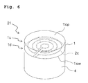
- the sliding component 21 related to the second modified example differs from the sliding component 20 related to the second embodiment in that the conductive wire 2c is arranged within the liner 1 and that no reserve member 3 is provided, as depicted in Fig. 6 .
- Other respects are the same as those of the sliding component 20 related to the second embodiment.
- the conductive wire 2c is disposed within the liner 1, on the lower side of the center of the liner 1 in the up-down direction (thickness direction).
- a part, of the liner 1, positioned on the upper side of the inlying conductive wire 2c is referred to as an upper liner 1u (first conductive part), and a part, of the liner 1, positioned on the lower side of the inlying conductive wire 2c is referred to as a lower liner 1d (second conductive part).
- the method of using the sliding component 21 related to the second modified example is the same as that of the sliding component 20 related to the second embodiment.
- the sliding component 21 related to the second modified example can obtain the effects similar to those of the sliding component 20 related to the second embodiment. Further, in the sliding component 21 related to the second modified example, the conductive wire 2c is formed within the liner 1 and the lower liner 1d is disposed on the lower side of the conductive wire 2c. Thus, when the upper liner 1u is abraded and progression of wear of the liner 1 is detected, the lower liner 1d slidably supports the turn table 50 satisfactorily.
- the sliding component 21 related to the second modified example can obtain the same effects as the sliding component 20 related to the second embodiment, and the turn table 50 can be slidably supported, even after detection of wear of the upper liner 1u, with the same sliding performance as that before detection of wear of the upper liner 1u.
- the sliding component 21 related to the second modified example can be manufactured, for example, by the following method.
- the manufacturing method thereof is not particularly limited thereto.
- the conductive wire 2c is disposed in the liner 1 through insert molding.
- the liner 1 in which the conductive wire 2c is disposed is supported by the base 4.
- the following manner may be used instead of the insert molding. Namely, a part corresponding to the lower liner 1d of the liner 1 is formed first, the conductive wire 2c is arranged on the part, and then the conductive wire 2c is coated with PTFE to form a part corresponding to the upper liner 1u.
- the conductive wire 2c may be arranged at any position in the liner 1 in the up-down direction (thickness direction), like the sliding component 11 related to the first modified example.
- the conductive wire 2c may have any shape and any arrangement.
- the conductive wire 2c may be arranged to pass large areas of the lower surface of the liner 1 and the upper surface of the reserve member 3. In this case, occurrence of abrasion of the liner 1 can be detected satisfactorily, even when the abrasion of the liner 1 has occurred unevenly or locally.
- the conductive wire 2c may be a thin film (conductive film) covering a predetermined area of the reserve member 3.
- the wear due to sliding movement of the turn table 50 may locally occur in a radial direction of the lower part 50b of the turn table 50 due to, for example, the manufacturing tolerance of the turn table 50. Therefore, it is preferred that the conductive wire 2c be distributed to cover widely in the radial direction of the lower part 50b of the turn table 50.
- the conductive wires 2, 2c are not limited to extend on the same plane, the conductive wires 2, 2c may bend upward or downward at intermediate parts thereof.
- the conductive wire 2c depicted in Fig. 5A extends on the same plane, it may extend as follows. Namely, the conductive wire 2c spirals or coils in a plane from the outside to the inside, bends upward or downward nearly at the center of the spiral, bends again to follow a plane parallel to the spiral surface, and reaches the outside of the spiral. Or, two or more of conductive wires 2, 2c may be formed in the up-down direction.
- a second liner 1 and second conductive wires 2, 2c may be disposed on the lower side of the conductive wires 2, 2c and the reserve member 3 may be disposed on the lower side of the second conductive wires 2, 2c.
- first conductive wires 2, 2c and second conductive wires 2, 2c may formed in the liner 1 to overlap with each other in the up-down direction.
- the two or more of conductive wires 2, 2c overlapping with each other in the up-down direction may be configured to be identical to each other or different from each other. Arranging two or more of conductive wires 2, 2c overlapping with each other in the up-down direction enables gradual detection of wear of the liner 1.
- the conductive wires 2, 2c positioned on the upper side may be used to detect that about 70% of the liner 1 has been abraded, and the conductive wires 2, 2c positioned on the lower side may be used to detect that more than 90% of the liner 1 has been abraded.
- a receiver receiving the detecting signal may raise an alarm visually or aurally.
- the sliding components 10, 20 related to the first and second embodiments are used in the case that the turn table 50 is not electrically connected to the power source E disposed in the tower T.
- the sliding component 30 is effectively used in a case that the conductive turn table 50 is electrically connected to the power surface E disposed in the tower T.
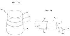
- the sliding component 30 related to the third embodiment is a cylindrical stacked structure.
- the sliding component 30 mainly includes a liner 1 (first sliding part), a conductive plate 2d (conductive member), an insulating film 5, and a base 4 and they are disposed in this order from the top of the sliding component 30.
- the liner 1 related to the third embodiment is a disk-shaped part which slidably supports the turn table 50 in the yaw system YS by making contact directly with the turn table 50.
- the liner 1 has a circular shape in plan view. It is preferred that the liner 1 be made of self-lubricating material, and in the above embodiments, the liner 1 is made of PTFE.
- the conductive plate 2d is a copper-alloy flat plate having a circular shape.
- the conductive plate 2d is disposed in parallel with an upper surface 1top of the liner 1 while being brought into contact under pressure with a lower surface of the liner 1.
- the base 4, which is made of steel material, is a disk-shaped member supporting the conductive plate 2d via the insulating film 5.
- the sliding component 30 related to the third embodiment is disposed on the upper surface of the flange F of the tower T.
- the sliding component 30 supports the nacelle N via the turn table 50 in a state that the liner 1 is in contact with the turn table 50.
- the turn table 50 and the nacelle N slide on the liner 1 to rotate around the rotational axis AN.
- the conductive plate 2d of the sliding component 30 is connected to a negative electrode of the power source E disposed in the tower T, as depicted in Fig. 7B .
- This configuration forms a circuit C 3 in an open state which is formed of the turn table 50, the power source E, and the conductive plate 2d.
- the turn table 50 has electric potential higher than that of the conductive plate 2d.
- the circuit C 3 is connected to the detector DT which detects whether or not current flows through the circuit C 3 so as to generate a digital signal based on the detection, the modem MO, and the transmitter TR those of which are disposed in the tower T.
- the liner 1 made of non-conductive PTFE is disposed between the turn table 50 and the conductive plate 2d.
- the state in which the turn table 50 has electric potential higher than that of the conductive plate 2d is maintained as long as the liner 1 is not yet worn away.
- the conductive turn table 50 made of iron makes contact with the conductive plate 2d, thereby electrically connecting the turn table 50 and the conductive plate 2d. This allows current to flow through the circuit C 3 in the closed state.
- the detecting circuit DT detects it and generates the digital signal.
- the digital signal is converted into an analog signal by the modem MO and the analog signal is transmitted to the transmitter TR.
- the transmitter TR transmits the received analog signal.
- the conductive plate 2d is disposed on the lower side of the liner 1, and the abrasion of the liner 1 can be detected by the contact between the conductive plate 2d and the turn table 50.
- transmitting the detection result for example, by wireless allows to easily know abrasion of the liner 1 in the sliding component 30 disposed at a high place without dispatching any worker to the top of the tower T.
- the sliding component 30 related to the third embodiment can detect in real time whether or not the liner 1 is abraded by using the conductive plate 2d.
- the abrasion of the liner 1 can be known as soon as it has occurred.
- the sliding component 30 related to the third embodiment can properly detect a rapid progression of wear (for example, due to a phenomenon such as frequent wind gusts) which would not be appropriately detected in periodic abrasion checks.
- the conductive plate 2d is disposed across the entire lower surface of the liner 1.
- the sliding component 30 related to the third embodiment can satisfactorily detect the uneven abrasion by the contact between the turn table 50 and the conductive plate 2d disposed on the lower side of a part with uneven abrasion.
- the sliding component 30 related to the third embodiment can detect abrasion of the liner 1 easily, thereby allowing a worker to know the timing for replacement of the sliding component 30 without an extra labor.
- a method for manufacturing the sliding component 30 related to the third embodiment is not particularly limited.
- the sliding component 30 related to the third embodiment can be manufactured by the following method. At first, the upper surface of the conductive plate 2d is coated with PTFE to form the liner 1. Then, the lower surface of the conductive plate 2d is fixed to the top surface of the base 4 via the insulating film 5.
- the power source E may be disposed in the nacelle N rather than disposed in the tower T.
- the turn table 50 may be connected to the negative electrode of the power source E rather than connected to the positive electrode, and the conductive plate 2d may be connected to the positive electrode of the power source E rather than connected to the negative electrode.
- the electrical connection between the power source E and the turn table 50 can be realized, for example, by using a brush.
- the conductive plate 2d may be a copper thin film.
- a second liner 1 and/or the reserve member 3 may be disposed on the lower side of the conductive plate 2d.
- the conductive plate 2d may be made of any other conductive material than copper alloy.
- the liner 1 is made of PTFE or self-lubricating resin containing PTFE.
- the present invention is not limited thereto.
- Self-lubricating material obtained by mixing a resin and a solid lubricant can be used as the material of the liner 1.
- usable resin include epoxy resin, acrylic resin, phenol resin, and polyether ketone resin.
- usable solid lubricant include PTFE and molybdenum disulfide.
- the self-lubricating material obtained by mixing the resin and the solid lubricant may further contain carbon fiber, glass fiber, and the like.
- the self-lubricating resin containing PTFE may be exemplified by an ultraviolet curable resin composition, which contains PTFE as the solid lubricant and an acrylate compound having an isocyanuric acid ring that is any of di-(2-acryloxyethyl) isocyanurate and ⁇ -caprolactone-modified tris-(2-acryloxyethyl) isocyanurate or a mixture of di-(2-acryloxyethyl) isocyanurate and tris-(2-acryloxyethyl) isocyanurate.
- the liner 1 is formed by subjecting the ultraviolet curable resin composition to ultraviolet curing.
- the ultraviolet curable resin composition contain 20 to 90% by weight of the acrylate compound having the isocyanuric acid ring and 10 to 50% by weight of PTFE.
- the ultraviolet curable resin composition may further contain at least one of bisphenol A epoxy acrylate, hydroxyethyl (meth)acrylate, isobornyl (meth)acrylate, pentaerythritol triacrylate and dipentaerythritol hexa(meth)acrylate, melamine cyanurate, and ethylene glycol di(meth)acrylate.
- the material of the liner 1 may be a fabric, which is made of PTFE and polyaramid fiber and is saturated with a phenol resin composition. Such fabric is disclosed, for example, in Japanese Patent Application Laid-open No. 2007-255712 .
- the material of the liner 1 may be a thermosetting acrylic composition containing 20% by weight or more of dipentaerythritol pentaacylate and 10% by weight or more of solid lubricant such as PTFE.
- a thermosetting acrylic composition is disclosed, for example, in United States Patent No. 6,180,574 .
- the material of the liner 1 may be a self-lubricating resin composition obtained by mixing 60 to 80% by weight of polyether ketone resin, 10 to 30% by weight of PTFE, 5 to 15% by weight of carbon fiber, and 15% by weight or less of aramid fiber.
- a self-lubricating resin composition is disclosed, for example, in Japanese Patent Application Laid-open No. 2011-247408 .
- the material of the liner 1 may be a Teflon (trade name) liner in which Teflon fiber, glass fiber, and other synthetic fiber are blended and the blended fiber is impregnated with phenolic resin. Further, the material of the liner 1 may be diamond-like carbon (DLC).
- Teflon trade name
- DLC diamond-like carbon
- the liner 1, the conductive wire 2, and the reserve member 3 are joined directly to each other.
- An insulating layer may be provided between the liner 1 and the conductive wire 2 or between the conductive wire 2 and the reserve member 3.
- a conductive liner may be used as the liner 1.
- the liner 1 may be a multi-layer liner made of a plurality of different materials.
- the reserve member 3 is made of polyetheretherketone.
- the present invention is not limited thereto.
- the reserve member 3 may be made of engineering plastic, such as polyacetal (POM), polyamide (PA), polycarbonate (PC), and polyethylene terephthalate (PET), instead of using polyetheretherketone (PEEK), or the reserve member 3 may be made of copper alloy.
- the reserve member 3 may be made of any of the self-lubricating materials described as the material of the liner 1.
- the reserve member 3 of the sliding component 10 related to the first embodiment is made of conductive material such as copper alloy
- an insulating film is provided between the conductive wire 2 and the reserve member 3. The insulating film prevents electrical connection between the first conductive wire 2a and the second conductive wire 2b which would be otherwise caused by the conductivity of the reserve member 3 made of copper alloy.
- the liner 1 may be made of the same material as the reserve member 3 or a material different from that of the reserve member 3.
- the material of the reserve member 3 be a material having hardness higher than that of material of the liner 1 and a wear property superior to that of material of the liner 1.
- the material of the reserve member 3 may have sliding performance inferior to that of material of the liner 1. Manufacturing costs of the sliding components 10, 20 can be reduced, accordingly.
- the sliding performance can be measured by a dynamic friction coefficient, and a material having a larger dynamic friction coefficient has higher sliding performance.
- the conductive wires 2, 2c are disposed on the upper surface of the reserve member 3 first, and then the conductive wires 2, 2c and the reserve member 3 are coated with resin such as PTFE to form the liner 1.
- the present invention is not limited thereto.
- the liner 1 may be manufactured by a method suitable for the material to be used for the liner 1. For example, when it is preferable to use the liner 1 formed into a plate shape in advance, the liner 1 in the plate shape may be bonded to the conductive wires 2, 2c or the reserve member 3. When it is preferred that the liner is formed by vapor deposition, the liner 1 may be formed on the conductive wires 2, 2c or the reserve member 3 by vapor deposition.
- a wear detection system DS related to the fourth embodiment mainly includes the sliding component 10 disposed in the wind power generator WG, the modem MO and the transmitter TR connected to the sliding component 10, a repeater R, and a receiver P.
- a digital signal indicating the occurrence of abrasion is transmitted to the modem MO.
- the modem MO converts the digital signal to an analog signal and transmits the analog signal to the transmitter TR.
- the analog signal send from the transmitter TR is transmitted to the receiver P via the repeater P.
- the analog signal received by the receiver P allows a user in a remote location to know that abrasion has occurred in the sliding component 10 in the wind power generator WG.
- the transmission of the signal from the transmitter TR to the receiver P may be made via a wired cable.
- the liner 1 and the reserve member 3 each have a circular shape in planar view.
- the liner 1 has a circular shape in planar view.
- the present invention is not limited to those.
- the liner 1 and the reserve member 3 may each have an approximately C-shape in plan view.
- Each of the sliding components 10, 11, 20, 21, and 30 provided with the approximately C-shaped liner is singly disposed on the flange F (see Fig. 2 ) of the tower T, unlike the sliding components 10, 11, 20, 21, and 30 provided with the circular-shaped liner 1.
- the sliding component provided with the approximately C-shaped liner continuously extends in a circumferential direction centering on the axis AN, with the brake pads 40 disposed in an opening of the C-shape.
- the conductive wire 2 depicted in Figs. 3A and 3B may be provided as a plurality of conductive wires 2 in the circumferential direction.
- the conductive wire 2 in the sliding components 10, 11 provided with the approximately C-shaped liner may have any other form.
- the conductive wire 2c in the sliding components 20, 21 provided with the approximately C-shaped liner may have any other form.
- the conductive plate 2d may have the same shape in planer view as the liner 1 and may extend across the entire lower surface of the liner.
- the brake pads 40 are used as brakes (means) regulating rotation of the turn table 50.
- the brake includes a mechanism or structure, which regulates rotation of the turn table 50 by making contact with or having no contact with the turn table 50 or a component connected to the turn table 50.
- the sliding components 10, 11, 20, 21, and 30 are used in the wind power generator WG.
- the present invention is not limited thereto.
- the turn table 50 in the wind power generator WG is an exemplary object related to the present invention.
- the object related to the present invention is not limited to the turn table 50.
- the sliding components 10, 11, 20, 21, and 30 related to the embodiments and the modified examples may be used for any object, and may be used for any purpose of sliding the object.
- the sliding components 10, 11, 20, 21, and 30 may be suitably used for the purpose of slidably supporting a heavy object in a place, such as on the sea, in a mountain, and in the ground, which is difficult to be accessed by a worker.
- the sliding components 10, 11, 20, 21, and 30 may be suitably used in a place which is easy to be accessed by a worker, and may be used for the purpose of slidably supporting a light object.
- the sliding components 10, 11, 20, 21, and 30 may be used in a positioning apparatus of a parabolic antenna, an movable portion of a mega solar panel, a guide pad of a flap strut track of an airplane, and the like.
- the present invention is not limited to the embodiments and the modified examples, provided that characteristics of the present invention can be obtained.
- the present invention includes any other embodiments which can be conceived in the range of technical ideas of the present invention.
- the sliding component related to the present invention can easily detect occurrence of wear. Thus, it is possible to reduce labor and costs required for maintenance of the wind power generator, thereby contributing to promotion of utilization of next-generation energy.
Landscapes
- Engineering & Computer Science (AREA)
- General Engineering & Computer Science (AREA)
- Mechanical Engineering (AREA)
- Life Sciences & Earth Sciences (AREA)
- Sustainable Development (AREA)
- Sustainable Energy (AREA)
- Chemical & Material Sciences (AREA)
- Combustion & Propulsion (AREA)
- Wind Motors (AREA)
- Sliding-Contact Bearings (AREA)
Abstract
Description
- The present invention relates to a sliding component configured to detect the occurrence of wear by using a conductive member disposed below a sliding surface, and a wear detection system using the same.
- In wind power generators, blades are required to always face in a windward direction during power generation in order to convert wind power into electric power efficiently. Thus, wind power generators typically include a nacelle which rotatably supports blades around a horizontal axis and a yaw system (yaw damper). The yaw system rotates the nacelle relative to a tower (a prop or strut) around a vertical axis based on, for example, detection of a direction of wind, thereby turning blades in the windward direction.
-
Patent document 1 discloses an exemplary yaw system. In the yaw system disclosed inpatent document 1, a nacelle slides on sliding pads disposed in a tower using power from an electric motor, and rotates on the tower around a vertical axis. - Patent Document 1: International Publication No.
2009/150716 - Allowing the nacelle to slide on the sliding pads wears away the sliding pads. Thus, the wear state of the sliding pads is required to be inspected periodically. The sliding pads, however, are disposed on the tower, that is, disposed at a high location, and thus an inspection of the wear state is not easy, involving a great deal of labor, and high risk.
- The present invention has been made to solve the above problem. An object of the present invention is to provide a sliding component which allows to easily recognize the wear state. Such a sliding member can be for example a sliding pad. Another object of the present invention is to provide a wear detection system configured to easily detect the wear state of the sliding member.
- According to a first aspect of the present invention, there is provided a sliding component including: a first sliding part which is non-conductive and which has a sliding surface; and a conductive member provided in the first sliding part or provided on a side opposite to the sliding surface of the first sliding part.
- The sliding component related to the present invention includes the conductive member in the first sliding part or on the side opposite to the sliding surface of the first sliding part (the side opposite to the side at which the first sliding part makes contact with an object). Thus, the occurrence of wear in the first sliding part can be detected by detecting the conduction state in the conductive member.
- The sliding component related to the present invention may further include a second sliding part on the side opposite to the sliding surface of the first sliding part. The conductive member may be positioned between the first sliding part and the second sliding part. The second sliding part slidably supports the object even after abrasion (worn away) of the first sliding part.
- In the sliding component related to the present invention, the second sliding part may be made of a material identical to a material of the first sliding part. In this case, the second sliding part slidably supports the object, even after detection of abrasion of the first sliding part, with the same sliding performance as that before detection of abrasion of the first sliding part.
- In the sliding component related to the present invention, the first sliding part may be made of self-lubricating resin. Using the self-lubricating resin enables to slidably support the object more satisfactorily while maintaining insulation performance. It is preferred that the self-lubricating resin contain polytetrafluoroethylene.
- In the sliding component related to the present invention, the conductive member may extend in a plane and the sliding surface of the first sliding part may be substantially parallel to the plane in which the conductive member extends. In this configuration, the distance between the sliding surface of the first sliding part and the conductive member is constant. Thus, even if uneven wear has occurred in the sliding surface, the uneven wear is detected at the same timing regardless of the position of uneven wear.
- The sliding component related to the present invention may further include a base being provided on a side opposite to the sliding surface of the first sliding part and holding the first sliding part and the conductive member. This configuration enables easy setting and replacement of the sliding component by handling the base.
- In the sliding component related to the present invention, the conductive member may include a first conductive part and a second conductive part which are positioned on a same plane and are not electrically connected to each other. In this case, each of the first conductive part and the second conductive part may include a plurality of arc-like line parts having mutually different radii and a connecting line part connecting the plurality of arc-like line parts with each other.
- In the sliding component related to the present invention, the conductive member may be a single continuous conductive wire. In this case, the conductive wire may extend so as to make arcs having mutually different radii.
- In the sliding component related to the present invention, the conductive member may be a flat plate or a film.
- According to a second aspect of the present invention, there is provided a yaw system configured to adjust a direction of a nacelle of a wind power generator, the yaw system including:
- a rotating body mounted to the nacelle; and
- the sliding component according to the first aspect which is configured to slidably support the rotating body; and
- a brake configured to restrain the rotating body.
- The yaw system related to the present invention can easily detect abrasion of the first sliding part of the sliding component by detecting the conduction state in the conductive member. Thus, it is possible to prevent the increase in operational costs which would be otherwise caused by frequent wear checks.
- According to a third aspect of the present invention, there is provided a wear detection system configured to detect wear of a sliding component caused by friction between the sliding component and a conductive object, the system including:
- the sliding component according to the first aspect in which the conductive member includes the first conductive part and the second conductive part which are positioned on the same plane and are not electrically connected to each other; and
- a detector electrically connected to the first conductive part and the second conductive part of the sliding component and configured to detect an electrical connection between the first conductive part and the second conductive part.
- According to a fourth aspect of the present invention, there is provided a wear detection system configured to detect wear of a sliding component caused by friction between the sliding component and a non-conductive object, the system including:
- the sliding component according to the first aspect in which the conductive member is the single continuous conductive wire; and
- a detector electrically connected to the conductive wire of the sliding component and configured to detect a cutoff of the conductive wire.
- In the wear detection systems according to the third and fourth aspects of the present invention, the detector connected to the conductive member can detect the change in the conduction state of conductive member of the sliding component which is caused by wear of the first sliding part of the sliding component. Thus, it is possible to easily detect occurrence of abrasion of the first sliding part. The wear detection system according to the third aspect is suitable for detecting wear of the sliding component caused by the conductive object. The wear detection system according to the fourth aspect is suitable for detecting wear of the sliding component caused by the non-conductive object.
- According to a fifth aspect of the present invention, there is provided a wear detection system configured to detect wear of a sliding component caused by friction between the sliding component and a conductive object, the system including:
- the sliding component according to the first aspect in which the conductive member is in a form of the flat plate or the film; and
- a detector electrically connected to the conductive member of the sliding component and the conductive object and configured to detect an electrical connection between the conductive member and the conductive object.
- In the wear detection system according to the fifth aspect of the present invention, wear of the first sliding part, which is caused by sliding the conductive object on the sliding component, is detected by use of the detector detecting the electrical connection between the conductive object and the conductive member
- The wear detection systems according to the third to fifth aspects may further include a transmitter connected to the detector and a receiver configured to receive a signal transmitted from the transmitter. This configuration allows wear of the first sliding part to be easily detected in a remote location.
- The yaw system according to the second aspect may include any of the wear detection systems according to the third to fifth aspects. Further, the present invention can provide a wind power generator provided with the yaw system according to the second aspect.
- According to the present invention, there is provided the sliding component which can easily recognize a wear state of the sliding member. Further, there is provided the yaw system, wear detection system, and wind power generator which can easily recognize a wear state of the sliding member.
-
-
Fig. 1A schematically depicts a wind power generator related to the first embodiment of the present invention, andFig. 1 B is an enlarged sectional view of the area Ib ofFig. 1 A surrounded by dashed-dotted lines, the view being obtained by cutting a yaw system, which includes a sliding component related to the first embodiment, along a surface including a rotational center axis of a nacelle. -
Fig. 2 depicts arrangement of components of the yaw system as viewed from above. -
Fig. 3A is an exploded view of the sliding component related to the first embodiment of the present invention, andFig. 3B is a circuit diagram including a conductive wire provided for the sliding component related to the first embodiment of the present invention. -
Fig. 4A is a perspective view of a sliding component related to a modified example of the first embodiment of the present invention, andFig. 4B is a cross-sectional view of the sliding component obtained by cutting the sliding component along a surface including an end 2bt and being perpendicular to an upper surface 1top. -
Fig. 5A is an exploded view of a sliding component related to the second embodiment of the present invention, andFig. 5B is a circuit diagram including a conductive wire provided for the sliding component related to the second embodiment of the present invention. -
Fig. 6 is a perspective view of a sliding component related to a modified example of the second embodiment of the present invention. -
Fig. 7A is an exploded view of a sliding component related to the third embodiment of the present invention, andFig. 7B is a circuit diagram including a conductive plate provided for the sliding component related to the third embodiment of the present invention. -
Fig. 8 schematically depicts a wear detection system related to the fourth embodiment of the present invention. - An explanation will be made about the first embodiment of the present invention with reference to
Figs. 1 to 3 . - At first, an explanation will be made about a wind power generator WG to which a sliding component related to the present invention is applicable and a yaw system YS provided for the wind power generator WG with reference to
Figs. 1A and 1B . A slidingcomponent 10 related to the first embodiment can be used as a part of the yaw system YS. - As depicted in
Fig. 1A , the wind power generator WG mainly includes a hub H, three blades B mounted to the hub H, a nacelle N which supports the hub H such that the hub H can rotate around a horizontal axis, and a tower T which supports the nacelle N such that the nacelle N can rotate around a vertical axis. Rotating the hub H by the blades B receiving wind generates rotative force, and the rotative force is transmitted to an electric generator (not depicted in the drawings) disposed in the nacelle N via a speed-up gearbox (not depicted in the drawings) disposed in the nacelle N. The electricity generated by the electric generator is transmitted to the outside through cables (not depicted in the drawings) disposed in the tower T. - The wind power generator WG performs yaw control, in which the nacelle N is pivoted such that the hub H always faces in a windward direction, in order to receive surrounding wind without waste. The yaw control is performed by the yaw system YS disposed in the nacelle N and the tower T.
- As depicted in
Fig. 1B , the yaw system YS mainly includes a turn table (rotating plate, rotating body) 50 mounted on the lower side of the nacelle N, slidingcomponents 10 disposed on a flange F, which is provided in the vicinity of the top of the tower T, at predetermined intervals in a circumferential direction of the flange F,brake pads 40, anelectric motor 70 fixed to the turn table 50, and aring gear 90 formed in a top plate Tt of the tower T. The yaw system YS rotates the nacelle N around a rotational axis AN. -
Fig. 2 depicts a positional relation of the turn table 50, the slidingcomponents 10, thebrake pad 40, and thering gear 90 in the yaw system YS as viewed from the upper side.Fig. 2 is a cross-sectional view taken along the line II-II inFig. 1B . InFig. 2 , the slidingcomponents 10, thebrake pad 40, the flange F, and the tower T those of which are disposed on the lower side of this cross-section are indicated by solid lines, ashaft part 50c (as described later) of the turn table 50, thering gear 90, and a pinion gear 71 (as described later) attached to theelectric motor 70 those of which are disposed on the upper side of this cross-section are indicated by dashed lines. Note thatFig. 1B is a cross-sectional view taken along the line Ib-Ib inFig. 2 . - The turn table 50 is an iron plate constituting a part of the nacelle N. The turn table 50 includes an
upper part 50a which is a bottom surface of the nacelle N, a disk-shapedlower part 50b positioned on the lower side of theupper part 50a, and theshaft part 50c connecting theparts upper part 50a,lower part 50b, andshaft part 50c are coaxially arranged. The turn table 50 rotates in a state that the lower surface of thelower part 50b is in contact with and supported by the sliding components 10 (seeFig. 2 ) disposed on the flange F. Theshaft part 50c of the turn table 50 has a diameter smaller than those of the upper andlower parts shaft part 50c is supported by a shaft (not depicted in the drawings) to rotate around the rotational axis AN. Rotation of the turn table 50 rotates the nacelle N integrally with the turn table 50 around the rotational axis AN. - The
brake pads 40 sandwich the disk-shapedlower part 50b from upper and lower sides based on a command from a controller (not depicted in the drawings), thereby controlling the rotation of the turn table 50. As viewed in plan view, thebrake pad 40 and slidingcomponents 10 are arranged at regular intervals such that they are positioned rotationally symmetric in the circumferential direction with the rotational axis AN of the nacelle N as the center (Fig. 2 ). - The
electric motor 70 is a motor which is controlled by the controller (not depicted in the drawings). Theelectric motor 70 rotates thepinion gear 71 engaging with thering gear 90, thereby rotating the nacelle N relative to the tower T via theshaft part 50c of the turn table 50. The controller receives a measurement result, such as a wind direction, from a measuring unit (not depicted in the drawings) and controls driving of theelectric motor 70 based on the measurement result. - Subsequently, the sliding
component 10 related to the first embodiment will be explained in detail. - As depicted in
Fig. 3A , the slidingcomponent 10 related to the first embodiment has a cylindrical shape. The slidingcomponent 10 mainly includes a liner (first sliding part) 1, a conductive wire (conductive member) 2, a reserve member (second sliding part) 3, and abase 4, and they are arranged from a sliding surface 1top of theliner 1 to thebase 4 in that order. In the following explanation, the side on which theliner 1 is disposed is defined as the upper side of the slidingcomponent 10 and the side on which thebase 4 is disposed is defined as the lower side of the slidingcomponent 10. A direction perpendicular to the up-down direction is referred to as a horizontal direction. - The
liner 1 is a disk-shaped part which slidably supports the turn table 50 in the yaw system YS by making contact directly with the turn table 50. Theliner 1 having the substantially horizontal sliding surface 1top is circular-shaped as viewed in planer view. Theliner 1 is made of non-conductive material, in particular, it is preferred that theliner 1 be made of self-lubricating resin material. In the first embodiment, theliner 1 is made of polytetrafluoroethylene (PTFE) or self-lubricating resin containing PTFE. Materials, such as resin, usable for theliner 1 related to the present invention will be described later. - The
conductive wire 2 is arranged in an approximately horizontal plane (that is, in the same plane) on the lower side of theliner 1, in order words, theconductive wire 2 is arranged substantially in parallel with the sliding surface 1top of theliner 1. Theconductive wire 2 is formed of a first conductive wire (first conductive part) 2a and a second conductive wire (second conductive part) 2b which are not electrically connected to each other. Each of the firstconductive wire 2a and the secondconductive wire 2b includes arc-like line parts having mutually different radii and a connecting line part connecting the arc-like line parts with each other. Namely, the firstconductive wire 2a includes four approximately semicircular wires arranged concentrically and an end 2at (Fig. 3B ) connecting the four wires at the center of the arc in a radial direction; and the secondconductive wire 2b includes three approximately semicircular wires arranged concentrically and an end 2bt connecting the three wires at the center of the arc in a radial direction. As depicted inFig. 3A , the firstconductive wire 2a and the secondconductive wire 2b are disposed between theliner 1 and thereserve member 3 while being separated from each other in the horizontal direction. Specifically, the firstconductive wire 2a and the secondconductive wire 2b are disposed such that six ends of three approximately semicircular wires of the secondconductive wire 2b and eight ends of four approximately semicircular wires of the firstconductive wire 2a overlap with each other in a certain radial direction and that the six ends and the eight ends are separate from each other in another radial direction perpendicular to the certain radial direction. This configuration defines gaps g aligned in the another radial direction between the firstconductive wire 2a and the secondconductive wire 2b. - The
reserve member 3, which has a disk-shape like theliner 1, is disposed on the lower side of theconductive wire 2. After theliner 1 is abraded (worn away), thereserve member 3 makes contact with the turn table 50 substituting theliner 1 and slidably supports the turn table 50. Thus, it is preferred that thereserve member 3 itself has appropriate slidability. In the first embodiment, thereserve member 3 is made of polyetheretherketone (PEEK). - The
base 4, which is made of steel material, is a disk-shaped member supporting thereserve member 3 from the lower side. - The sliding
component 10 has a configuration in which the above components are brought into tight contact with each other in the up-down direction. More specifically, theliner 1 and thereserve member 3 hold theconductive wire 2 while making tight contact with theconductive wire 2 from upper and lower sides. Thebase 4 supports thereserve member 3, theconductive wire 2, and theliner 1 in this order while contacting tightly with the lower surface of thereserve member 3. In the yaw system YS, thebase 4 of the slidingcomponent 10 is disposed on a recessed part formed in the flange F of the tower T. - Subsequently, an explanation will be made about a method of using the sliding
component 10 related to the first embodiment. - As depicted in
Fig. 1B , the slidingcomponent 10 related to the first embodiment is disposed on the upper surface of the flange F of the tower T to support the nacelle N via the turn table 50 with theliner 1 making contact with the turn table 50. When receiving the rotative force from theelectric motor 70, the turn table 50 and the nacelle N slide on theliner 1 to rotate around the rotational axis AN. - Further, in the state that the sliding
component 10 is disposed on the flange F of the tower T, the firstconductive wire 2a is connected to a positive electrode of a power source E disposed in the tower T via the end 2at, and the secondconductive wire 2b is connected to a negative electrode of the power source E via the end 2bt, as depicted inFig. 3B . This configuration forms a circuit C1 in an open state which includes the firstconductive wire 2a, the secondconductive wire 2b, and the power source E. The firstconductive wire 2a has electric potential higher than that of the secondconductive wire 2b. The circuit C1 is connected to a detector DT which detects whether or not current flows through the circuit C1 so as to generate a digital signal based on the detection, a modem MO, and a transmitter TR those of which are disposed in the tower T. - As depicted in
Fig. 3A , the firstconductive wire 2a and the secondconductive wire 2b are disposed with gaps g intervening therebetween. Thus, the firstconductive wire 2a is not electrically connected to the secondconductive wire 2b as long as theliner 1 is not yet worn away. However, when the wear of theliner 1 has become severe due to friction between theliner 1 and the turn table 50, the conductive turn table 50 made of metal makes contact with the firstconductive wire 2a and the secondconductive wire 2b. This contact electrically connects the firstconductive wire 2a and the secondconductive wire 2b, and thus current flows through the circuit C1 in a closed state. - When the circuit C1 becomes closed, the detecting circuit DT detects the closed state and generates the corresponding digital signal. The digital signal is converted into an analog signal by the modem MO and the analog signal is transmitted to the transmitter TR. The transmitter TR transmits the received analog signal.
- When not only the
liner 1 but also theconductive wire 2 has disappeared due to wear, thereserve member 3 makes contact directly with the turn table 50 and slidably supports the turn table 50. Thereserve member 3 is made of PEEK as described above. Thus, thereserve member 3 has good slidability although the slidability thereof is inferior to that of theliner 1 made of PTFE or the self-lubricating resin containing PTFE. Accordingly, slidable support of the turn table 50 is maintained by thereserve member 3 even after theliner 1 is abraded. - Such a configuration enables the sliding
component 10 having the abradedliner 1 to be replaced by a new slidingcomponent 10 while thereserve component 3 is slidably supporting the turn table 50 after detection of abrasion of theliner 1. Thus, the yaw system YS is prevented from being damaged. - Effects of the sliding
component 10 related to the first embodiment are summarized as follows. - In the sliding
component 10 related to the first embodiment, theconductive wire 2 is disposed on the lower side of theliner 1, and abrasion of theliner 1 can be detected by the contact between theconductive wire 2 and the turn table 50. Thus, in the slidingcomponent 10 related to the first embodiment, transmitting the detection result, for example, by wireless allows a worker to easily know abrasion of theliner 1 in the slidingcomponent 10 disposed at a high location without dispatching any worker to the top of the tower T. - The sliding
component 10 related to the first embodiment can detect abrasion of theliner 1 in real time by using theconductive wire 2. Thus, regular abrasion checks are unnecessary. The slidingcomponent 10 related to the first embodiment detects abrasion of theliner 1 instantly, and thus the slidingcomponent 10 related to the first embodiment can properly detect rapid progression of wear which may be caused by a phenomenon such as frequent wind gusts and which is not appropriately detected in periodic abrasion checks. - In the sliding
component 10 related to the first embodiment, the gaps g aligned in a row are defined between the extremities of four wires of the firstconductive wire 2a and the extremities of three wires of the secondconductive wire 2b. When the turn table 50 electrically connects an end of the firstconductive wire 2a and an end of the secondconductive wire 2b defining any one of the gaps g, the firstconductive wire 2a is electrically connected to the secondconductive wire 2b and abrasion of theliner 1 is detected. Thus, in the slidingcomponent 10 related to the first embodiment, even when abrasion of theliner 1 has occurred partially or locally, this abrasion can be detected satisfactorily. - As described above, the sliding
component 10 related to the first embodiment can detect abrasion of theliner 1 easily, which allows a worker to know the timing for replacement of the slidingcomponent 10 without labor. Thus, even if the slidingcomponent 10 related to the first embodiment is used in the vicinity of a brake unit, which is more likely to damage the liner by scattering wear powder of a brake pad, it is possible to prevent the increase in operational costs which would be otherwise caused by frequent wear checks. - In the sliding
component 10 related to the first embodiment, thereserve member 3 is disposed on the lower side of theconductive wire 2. Thus, thereserve member 3 slidably supports the turn table 50 reasonably well after theliner 1 has disappeared due to wear. This gives sufficient time after abrasion of theliner 1 is detected until the replacement of the slidingcomponent 10 is actually performed. - A method for manufacturing the sliding
component 10 related to the first embodiment is not particularly limited. The slidingcomponent 10 related to the first embodiment can be manufactured, for example, by the following method. At first, theconductive wire 2 is disposed on the upper surface of thereserve member 3, and theconductive wire 2 and thereserve member 3 are coated with self-lubricating resin containing PTFE to form theliner 1. Next, the lower surface of thereserve member 3 is fixed to the top surface of thebase 4 to support, by thebase 4, theliner 1,conductive wire 2, andreserve member 3 formed integrally. - Subsequently, an explanation will be made about a sliding
component 11 related to the first modified example of the first embodiment with reference toFigs. 4A and 4B . The slidingcomponent 11 related to the first modified example differs from the slidingcomponent 10 related to the first embodiment in that theconductive wire 2 is arranged within theliner 1 and that noreserve member 3 is provided, as depicted inFigs. 4A and 4B . Other respects are the same as those of the slidingcomponent 10 related to the first embodiment. - In the sliding
component 11 related to the first modified example, theconductive wire 2 is disposed within theliner 1, on the lower side of the center of theliner 1 in the up-down direction (thickness direction), positioned in a plane substantially parallel to an upper surface 1top of theliner 1. In the following, a part of theliner 1 positioned on the upper side of the inlyingconductive wire 2 is referred to as anupper liner 1u, and a part of theliner 1 positioned on the lower side of the inlyingconductive wire 2 is referred to as alower liner 1d. - The method of using the sliding
component 11 related to the first modified example is the same as that of the slidingcomponent 10 related to the first embodiment. - The sliding
component 11 related to the first modified example can obtain effects similar to those of the slidingcomponent 10 related to the first embodiment. Further, in the slidingcomponent 11 related to the first modified example, theconductive wire 2 is formed within theliner 1 and thelower liner 1d is disposed on the lower side of theconductive wire 2. Thus, when theupper liner 1u is abraded and progression of wear of theliner 1 is detected, thelower liner 1d slidably supports the turn table 50 satisfactorily. Accordingly, the slidingcomponent 11 related to the first modified example can obtain the same effects as the slidingcomponent 10 related to the first embodiment, and the turn table 50 can be slidably supported, even after detection of wear of theupper liner 1u, with the same sliding performance as that before detection of wear of theupper liner 1u. - In the manufacture of the sliding
component 11 related to the first modified example, at first, theconductive wire 2 and theliner 1 are formed integrally through insert molding so that theconductive wire 2 is disposed within theliner 1. Next, theliner 1 in which theconductive wire 2 is disposed is supported by thebase 4. Or, the following manner may be used instead of the insert molding. Namely, a part corresponding to thelower liner 1d of theliner 1 is formed first, theconductive wire 2 is arranged on the part, and then self-lubricating resin containing PTFE is coated on theconductive wire 2 and cured to form a part corresponding to theupper liner 1u. - In the sliding
component 11 related to the first modified example, theconductive wire 2 may be arranged at any position in theliner 1 in the up-down direction (thickness direction). When theconductive wire 2 is disposed closer to a lower surface 1low of theliner 1 in the up-down direction to increase the thickness of theupper liner 1u, the elapsed time until progression of wear in theliner 1 is detected becomes longer. In this case, however, the operational time of the slidingcomponent 11 after detection of wear of theupper liner 1u becomes shorter. When theconductive wire 2 is disposed closer to the upper surface 1top of theliner 1 in the up-down direction to increase the thickness of thelower liner 1d, the elapsed time until detection of wear in theliner 1 becomes shorter. In this case, however, the operational time of the slidingcomponent 11 after detection of wear in theupper liner 1u becomes longer. This provides enough time after wear detection in theliner 1 until replacement of the slidingcomponent 11 is actually performed. - In the first embodiment and the first modified example, specific shapes and arrangements of the first
conductive wire 2a and the secondconductive wire 2b have been described. Those, however, are merely examples and any other configuration may be used provided that one of thewires wires wires wires wires conductive wire 2a and the secondconductive wire 2b have a linear shape. The firstconductive wire 2a and the secondconductive wire 2b, however, may have a belt-like shape or may be a thin film (conductive film) covering a predetermined area of thereserve member 3. Each gap defined between the firstconductive wire 2a and the secondconductive wire 2b may have any spacing distance and any arrangement, and any number of gaps may be provided. Increasing the number of gaps g enable good detection of occurrence of abrasion, even when the abrasion of theliner 1 has occurred unevenly or locally. The wear due to sliding movement of the turn table 50 may locally occur in a radial direction of thelower part 50b of the turn table 50 due to, for example, the manufacturing tolerance of the turn table 50. Therefore, it is preferred that the firstconductive wire 2a and the secondconductive wire 2b be distributed to cover widely in the radial direction of thelower part 50b of the turn table 50. - An explanation will be made about a sliding component related to the second embodiment with reference to
Fig. 5 . - The sliding
component 10 in the first embodiment is an example of an sliding component effectively used with the conductive turn table 50. In the second embodiment, it will be explained a slidingcomponent 20 which is effectively used with a turn table 50 made of non-conductive material, such as plastic. - The sliding
component 20 related to the second embodiment has the same structure as the slidingcomponent 10 related to the first embodiment, except that aconductive wire 2c has a shape different from that of theconductive wire 2 of the slidingcomponent 10 related to the first embodiment. - The
conductive wire 2c of the slidingcomponent 20 related to the second embodiment is a conductive wire (conductive body) extending so as to make arcs having mutually different radii on the same plane. More specifically, as depicted inFig. 5A , theconductive wire 2c is a single conductive wire which is disposed to follow four concentric circles one by one so as to passing almost all areas of the lower surface of theliner 1 and the upper surface of thereserve member 3. Theconductive wire 2c has ends 2ct1, 2ct2. - Similar to the sliding
component 10 related to the first embodiment, the slidingcomponent 20 related to the second embodiment is disposed on the flange F of the tower T. The slidingcomponent 20 supports the turn table 50 and the nacelle N in a state that theliner 1 is in contact with the turn table 50. When receiving the rotative force from theelectric motor 70, the turn table 50 and the nacelle N slide on theliner 1 to rotate around the rotational axis AN. - Further, in the state that the sliding
component 20 is disposed on the flange F of the tower T, the end 2ct1 of theconductive wire 2c is connected to a positive electrode of the power source E disposed in the tower T, and the end 2ct2 of theconductive wire 2c is connected to a negative electrode of the power source E, as depicted inFig. 5B . This configuration forms a circuit C2 in a closed state which is formed of theconductive wire 2c and the power source E. Current flows through the circuit C2. The circuit C2 is connected to the detector DT which detects whether or not current flows through the circuit C2 so as to generate a digital signal based on the detection, the modem MO, and the transmitter TR those of which are disposed in the tower T. - Current flows through the
conductive wire 2c as long as theliner 1 is not yet worn away. However, when the wear of theliner 1 has become severe due to friction between theliner 1 and the turn table 50, the non-conductive turn table 50 slides on theconductive wire 2c while making contact therewith and breaks theconductive wire 2c. This changes the state in the circuit C2 from the closed state to the open state, thereby interrupting current. - When the state in the circuit C2 has changed from the closed state to the open state, the detecting circuit DT detects this change and generates a corresponding digital signal. The modem MO converts the digital signal to an analog signal and transmit the analog signal to the transmitter TR. The transmitter TR transmits the received analog signal.
- The sliding
component 20 related to the second embodiment can provide the effects similar to those of the slidingcomponent 10 related to the first embodiment. The slidingcomponent 20 related to the second embodiment can be manufactured by the same method as the slidingcomponent 10 related to the first embodiment. - Subsequently, an explanation will be made about a sliding
component 21 related to the second modified example of the second embodiment with reference toFig. 6 . The slidingcomponent 21 related to the second modified example differs from the slidingcomponent 20 related to the second embodiment in that theconductive wire 2c is arranged within theliner 1 and that noreserve member 3 is provided, as depicted inFig. 6 . Other respects are the same as those of the slidingcomponent 20 related to the second embodiment. - In the sliding
component 21 related to the second modified example, theconductive wire 2c is disposed within theliner 1, on the lower side of the center of theliner 1 in the up-down direction (thickness direction). In the following, a part, of theliner 1, positioned on the upper side of the inlyingconductive wire 2c is referred to as anupper liner 1u (first conductive part), and a part, of theliner 1, positioned on the lower side of the inlyingconductive wire 2c is referred to as alower liner 1d (second conductive part). - The method of using the sliding
component 21 related to the second modified example is the same as that of the slidingcomponent 20 related to the second embodiment. - The sliding
component 21 related to the second modified example can obtain the effects similar to those of the slidingcomponent 20 related to the second embodiment. Further, in the slidingcomponent 21 related to the second modified example, theconductive wire 2c is formed within theliner 1 and thelower liner 1d is disposed on the lower side of theconductive wire 2c. Thus, when theupper liner 1u is abraded and progression of wear of theliner 1 is detected, thelower liner 1d slidably supports the turn table 50 satisfactorily. Accordingly, the slidingcomponent 21 related to the second modified example can obtain the same effects as the slidingcomponent 20 related to the second embodiment, and the turn table 50 can be slidably supported, even after detection of wear of theupper liner 1u, with the same sliding performance as that before detection of wear of theupper liner 1u. - The sliding
component 21 related to the second modified example can be manufactured, for example, by the following method. The manufacturing method thereof, however, is not particularly limited thereto. At first, theconductive wire 2c is disposed in theliner 1 through insert molding. Next, theliner 1 in which theconductive wire 2c is disposed is supported by thebase 4. Or, the following manner may be used instead of the insert molding. Namely, a part corresponding to thelower liner 1d of theliner 1 is formed first, theconductive wire 2c is arranged on the part, and then theconductive wire 2c is coated with PTFE to form a part corresponding to theupper liner 1u. - In the sliding
component 21 related to the second modified example, theconductive wire 2c may be arranged at any position in theliner 1 in the up-down direction (thickness direction), like the slidingcomponent 11 related to the first modified example. - In the second embodiment and the second modified example, the
conductive wire 2c may have any shape and any arrangement. Theconductive wire 2c may be arranged to pass large areas of the lower surface of theliner 1 and the upper surface of thereserve member 3. In this case, occurrence of abrasion of theliner 1 can be detected satisfactorily, even when the abrasion of theliner 1 has occurred unevenly or locally. Theconductive wire 2c may be a thin film (conductive film) covering a predetermined area of thereserve member 3. The wear due to sliding movement of the turn table 50 may locally occur in a radial direction of thelower part 50b of the turn table 50 due to, for example, the manufacturing tolerance of the turn table 50. Therefore, it is preferred that theconductive wire 2c be distributed to cover widely in the radial direction of thelower part 50b of the turn table 50. - In the embodiments and the modified examples, the
conductive wires conductive wires conductive wire 2c depicted inFig. 5A extends on the same plane, it may extend as follows. Namely, theconductive wire 2c spirals or coils in a plane from the outside to the inside, bends upward or downward nearly at the center of the spiral, bends again to follow a plane parallel to the spiral surface, and reaches the outside of the spiral. Or, two or more ofconductive wires second liner 1 and secondconductive wires conductive wires reserve member 3 may be disposed on the lower side of the secondconductive wires conductive wires conductive wires liner 1 to overlap with each other in the up-down direction. The two or more ofconductive wires conductive wires liner 1. For example, theconductive wires liner 1 has been abraded, and theconductive wires liner 1 has been abraded. When theconductive wires liner 1, a receiver receiving the detecting signal may raise an alarm visually or aurally. - An explanation will be made about a sliding
component 30 related to the third embodiment with reference toFig. 7 . - The sliding
components Fig. 7 , the slidingcomponent 30 is effectively used in a case that the conductive turn table 50 is electrically connected to the power surface E disposed in the tower T. - As depicted in
Fig. 7A , the slidingcomponent 30 related to the third embodiment is a cylindrical stacked structure. The slidingcomponent 30 mainly includes a liner 1 (first sliding part), aconductive plate 2d (conductive member), an insulatingfilm 5, and abase 4 and they are disposed in this order from the top of the slidingcomponent 30. - Like the
liner 1 related to the first and second embodiments, theliner 1 related to the third embodiment is a disk-shaped part which slidably supports the turn table 50 in the yaw system YS by making contact directly with the turn table 50. Theliner 1 has a circular shape in plan view. It is preferred that theliner 1 be made of self-lubricating material, and in the above embodiments, theliner 1 is made of PTFE. - The
conductive plate 2d is a copper-alloy flat plate having a circular shape. Theconductive plate 2d is disposed in parallel with an upper surface 1top of theliner 1 while being brought into contact under pressure with a lower surface of theliner 1. Thebase 4, which is made of steel material, is a disk-shaped member supporting theconductive plate 2d via the insulatingfilm 5. - Subsequently, an explanation will be made about a method of using the sliding
component 30 related to the third embodiment. - As depicted in
Fig. 1B , the slidingcomponent 30 related to the third embodiment is disposed on the upper surface of the flange F of the tower T. The slidingcomponent 30 supports the nacelle N via the turn table 50 in a state that theliner 1 is in contact with the turn table 50. When receiving the rotative force from theelectric motor 70, the turn table 50 and the nacelle N slide on theliner 1 to rotate around the rotational axis AN. - Further, in the state that the sliding
component 30 is disposed on the flange F of the tower T, theconductive plate 2d of the slidingcomponent 30 is connected to a negative electrode of the power source E disposed in the tower T, as depicted inFig. 7B . This configuration forms a circuit C3 in an open state which is formed of the turn table 50, the power source E, and theconductive plate 2d. The turn table 50 has electric potential higher than that of theconductive plate 2d. The circuit C3 is connected to the detector DT which detects whether or not current flows through the circuit C3 so as to generate a digital signal based on the detection, the modem MO, and the transmitter TR those of which are disposed in the tower T. - As depicted in
Fig. 7B , theliner 1 made of non-conductive PTFE is disposed between the turn table 50 and theconductive plate 2d. Thus, the state in which the turn table 50 has electric potential higher than that of theconductive plate 2d is maintained as long as theliner 1 is not yet worn away. When the wear of theliner 1 has become severe due to friction between theliner 1 and the turn table 50, the conductive turn table 50 made of iron makes contact with theconductive plate 2d, thereby electrically connecting the turn table 50 and theconductive plate 2d. This allows current to flow through the circuit C3 in the closed state. - When the circuit C3 becomes the closed state, the detecting circuit DT detects it and generates the digital signal. The digital signal is converted into an analog signal by the modem MO and the analog signal is transmitted to the transmitter TR. The transmitter TR transmits the received analog signal.
- Effects of the sliding
component 30 related to the third embodiment are summarized as follows. - In the sliding
component 30 related to the third embodiment, theconductive plate 2d is disposed on the lower side of theliner 1, and the abrasion of theliner 1 can be detected by the contact between theconductive plate 2d and the turn table 50. Thus, in the slidingcomponent 30 related to the third embodiment, transmitting the detection result, for example, by wireless allows to easily know abrasion of theliner 1 in the slidingcomponent 30 disposed at a high place without dispatching any worker to the top of the tower T. - The sliding
component 30 related to the third embodiment can detect in real time whether or not theliner 1 is abraded by using theconductive plate 2d. Thus, unlike regular abrasion checks currently performed, for example, once every three or four months, the abrasion of theliner 1 can be known as soon as it has occurred. Thus, the slidingcomponent 30 related to the third embodiment can properly detect a rapid progression of wear (for example, due to a phenomenon such as frequent wind gusts) which would not be appropriately detected in periodic abrasion checks. - In the sliding
component 30 related to the third embodiment, theconductive plate 2d is disposed across the entire lower surface of theliner 1. Thus, even when theliner 1 is locally and unevenly abraded, the slidingcomponent 30 related to the third embodiment can satisfactorily detect the uneven abrasion by the contact between the turn table 50 and theconductive plate 2d disposed on the lower side of a part with uneven abrasion. - As described above, the sliding
component 30 related to the third embodiment can detect abrasion of theliner 1 easily, thereby allowing a worker to know the timing for replacement of the slidingcomponent 30 without an extra labor. Thus, it is possible to prevent the increase in operational costs which would be otherwise caused by frequent wear checks even if the slidingcomponent 30 related to the third embodiment is used in the vicinity of a brake unit, which is more likely to damage the liner by scattering wear powder of a brake pad. - A method for manufacturing the sliding
component 30 related to the third embodiment is not particularly limited. As an example, the slidingcomponent 30 related to the third embodiment can be manufactured by the following method. At first, the upper surface of theconductive plate 2d is coated with PTFE to form theliner 1. Then, the lower surface of theconductive plate 2d is fixed to the top surface of thebase 4 via the insulatingfilm 5. - In the third embodiment, the power source E may be disposed in the nacelle N rather than disposed in the tower T. The turn table 50 may be connected to the negative electrode of the power source E rather than connected to the positive electrode, and the
conductive plate 2d may be connected to the positive electrode of the power source E rather than connected to the negative electrode. When the power source E is arranged in the tower T, the electrical connection between the power source E and the turn table 50 can be realized, for example, by using a brush. - In the third embodiment, the
conductive plate 2d may be a copper thin film. In the third embodiment, asecond liner 1 and/or thereserve member 3 may be disposed on the lower side of theconductive plate 2d. In the third embodiment, theconductive plate 2d may be made of any other conductive material than copper alloy. - In the embodiments and the modified examples, the
liner 1 is made of PTFE or self-lubricating resin containing PTFE. The present invention, however, is not limited thereto. Self-lubricating material obtained by mixing a resin and a solid lubricant can be used as the material of theliner 1. Examples of usable resin include epoxy resin, acrylic resin, phenol resin, and polyether ketone resin. Examples of usable solid lubricant include PTFE and molybdenum disulfide. The self-lubricating material obtained by mixing the resin and the solid lubricant may further contain carbon fiber, glass fiber, and the like. The self-lubricating resin containing PTFE may be exemplified by an ultraviolet curable resin composition, which contains PTFE as the solid lubricant and an acrylate compound having an isocyanuric acid ring that is any of di-(2-acryloxyethyl) isocyanurate and ε-caprolactone-modified tris-(2-acryloxyethyl) isocyanurate or a mixture of di-(2-acryloxyethyl) isocyanurate and tris-(2-acryloxyethyl) isocyanurate. Theliner 1 is formed by subjecting the ultraviolet curable resin composition to ultraviolet curing. In this case, it is preferred that the ultraviolet curable resin composition contain 20 to 90% by weight of the acrylate compound having the isocyanuric acid ring and 10 to 50% by weight of PTFE. The ultraviolet curable resin composition may further contain at least one of bisphenol A epoxy acrylate, hydroxyethyl (meth)acrylate, isobornyl (meth)acrylate, pentaerythritol triacrylate and dipentaerythritol hexa(meth)acrylate, melamine cyanurate, and ethylene glycol di(meth)acrylate. - Further, the material of the
liner 1 may be a fabric, which is made of PTFE and polyaramid fiber and is saturated with a phenol resin composition. Such fabric is disclosed, for example, in Japanese Patent Application Laid-open No.2007-255712 liner 1 may be a thermosetting acrylic composition containing 20% by weight or more of dipentaerythritol pentaacylate and 10% by weight or more of solid lubricant such as PTFE. Such a thermosetting acrylic composition is disclosed, for example, in United States Patent No.6,180,574 . Further, the material of theliner 1 may be a self-lubricating resin composition obtained by mixing 60 to 80% by weight of polyether ketone resin, 10 to 30% by weight of PTFE, 5 to 15% by weight of carbon fiber, and 15% by weight or less of aramid fiber. Such a self-lubricating resin composition is disclosed, for example, in Japanese Patent Application Laid-open No.2011-247408 - Further, the material of the
liner 1 may be a Teflon (trade name) liner in which Teflon fiber, glass fiber, and other synthetic fiber are blended and the blended fiber is impregnated with phenolic resin. Further, the material of theliner 1 may be diamond-like carbon (DLC). - In the above embodiments, the
liner 1, theconductive wire 2, and thereserve member 3 are joined directly to each other. An insulating layer, however, may be provided between theliner 1 and theconductive wire 2 or between theconductive wire 2 and thereserve member 3. When the insulating layer is provided between theliner 1 and theconductive wire 2, a conductive liner may be used as theliner 1. For example, it is possible to use a metal liner formed of an interlayer and a Teflon-lead surface layer, the interlayer being obtained such that bronze powder is sintered, on a relatively-soft steel back metal, to have a porous state and the porous structure is filled with a mixture of Teflon and lead. - In the embodiments and the modified examples, the
liner 1 may be a multi-layer liner made of a plurality of different materials. - In the first and second embodiments, the
reserve member 3 is made of polyetheretherketone. The present invention, however, is not limited thereto. Thereserve member 3 may be made of engineering plastic, such as polyacetal (POM), polyamide (PA), polycarbonate (PC), and polyethylene terephthalate (PET), instead of using polyetheretherketone (PEEK), or thereserve member 3 may be made of copper alloy. Alternatively, thereserve member 3 may be made of any of the self-lubricating materials described as the material of theliner 1. - When the
reserve member 3 of the slidingcomponent 10 related to the first embodiment is made of conductive material such as copper alloy, an insulating film is provided between theconductive wire 2 and thereserve member 3. The insulating film prevents electrical connection between the firstconductive wire 2a and the secondconductive wire 2b which would be otherwise caused by the conductivity of thereserve member 3 made of copper alloy. - As described above, the
liner 1 may be made of the same material as thereserve member 3 or a material different from that of thereserve member 3. However, when considering that theliner 1 is a part which slidably supports the turn table 50 all the time and thereserve member 3 is a part which slidably supports the turn table 50 only for the period after theliner 1 has disappeared due to abrasion thereof before the slidingcomponents reserve member 3 be a material having hardness higher than that of material of theliner 1 and a wear property superior to that of material of theliner 1. On the other hand, the material of thereserve member 3 may have sliding performance inferior to that of material of theliner 1. Manufacturing costs of the slidingcomponents - In the manufacturing method related to the first and second embodiments, the
conductive wires reserve member 3 first, and then theconductive wires reserve member 3 are coated with resin such as PTFE to form theliner 1. The present invention, however, is not limited thereto. Theliner 1 may be manufactured by a method suitable for the material to be used for theliner 1. For example, when it is preferable to use theliner 1 formed into a plate shape in advance, theliner 1 in the plate shape may be bonded to theconductive wires reserve member 3. When it is preferred that the liner is formed by vapor deposition, theliner 1 may be formed on theconductive wires reserve member 3 by vapor deposition. - An explanation will be made about a wear detection system related to the fourth embodiment with reference to
Fig. 8 . - As depicted in
Fig. 8 , a wear detection system DS related to the fourth embodiment mainly includes the slidingcomponent 10 disposed in the wind power generator WG, the modem MO and the transmitter TR connected to the slidingcomponent 10, a repeater R, and a receiver P. - When abrasion has occurred in the sliding
component 10, a digital signal indicating the occurrence of abrasion is transmitted to the modem MO. The modem MO converts the digital signal to an analog signal and transmits the analog signal to the transmitter TR. The analog signal send from the transmitter TR is transmitted to the receiver P via the repeater P. The analog signal received by the receiver P allows a user in a remote location to know that abrasion has occurred in the slidingcomponent 10 in the wind power generator WG. - Any of the sliding
components component 10. The transmission of the signal from the transmitter TR to the receiver P may be made via a wired cable. - In the sliding
components liner 1 and thereserve member 3 each have a circular shape in planar view. In the slidingcomponent 30 related to the third embodiment and the slidingcomponents liner 1 has a circular shape in planar view. The present invention, however, is not limited to those. Theliner 1 and thereserve member 3 may each have an approximately C-shape in plan view. Each of the slidingcomponents Fig. 2 ) of the tower T, unlike the slidingcomponents liner 1. In particular, the sliding component provided with the approximately C-shaped liner continuously extends in a circumferential direction centering on the axis AN, with thebrake pads 40 disposed in an opening of the C-shape. In the slidingcomponents conductive wire 2 depicted inFigs. 3A and 3B may be provided as a plurality ofconductive wires 2 in the circumferential direction. Or, theconductive wire 2 in the slidingcomponents components conductive wire 2c depicted inFigs. 5A and 5B may be provided as a plurality ofconductive wires 2c in the circumferential direction. Or, theconductive wire 2c in the slidingcomponents component 30 provided with the approximately C-shaped liner, theconductive plate 2d may have the same shape in planer view as theliner 1 and may extend across the entire lower surface of the liner. In the embodiments, thebrake pads 40 are used as brakes (means) regulating rotation of the turn table 50. The present invention, however, is not limited thereto. It is possible to use any brake provided that the brake includes a mechanism or structure, which regulates rotation of the turn table 50 by making contact with or having no contact with the turn table 50 or a component connected to the turn table 50. - In the embodiments and the modified examples, the sliding
components components components components components - The present invention is not limited to the embodiments and the modified examples, provided that characteristics of the present invention can be obtained. The present invention includes any other embodiments which can be conceived in the range of technical ideas of the present invention.
- The sliding component related to the present invention can easily detect occurrence of wear. Thus, it is possible to reduce labor and costs required for maintenance of the wind power generator, thereby contributing to promotion of utilization of next-generation energy.
- 10, 11, 20, 21, 30 sliding component, 1 liner, 2, 2c conductive wire, 2d conductive plate, 3 reserve member, 4 base, 40 brake pad, 50 turn table, 70 electric motor, 90 ring gear, B blade, DT detector, MO modem, N nacelle, P repeater, R receiver, T tower, TR transmitter, WG wind power generator, YS yaw system.
Claims (19)
- A sliding component comprising:a first sliding part which is non-conductive and which has a sliding surface; anda conductive member provided in the first sliding part or provided on a side opposite to the sliding surface of the first sliding part.
- The sliding component according to claim 1, further comprising a second sliding part on the side opposite to the sliding surface of the first sliding part,
wherein the conductive member is positioned between the first sliding part and the second sliding part. - The sliding component according to claim 2, wherein the second sliding part is made of a material identical to a material of the first sliding part.
- The sliding component according to any one of claims 1 to 3, wherein the first sliding part is made of self-lubricating resin.
- The sliding component according to claim 4, characterized that the self-lubricating resin contains polytetrafluoroethylene.
- The sliding component according to any one of claims 1 to 5, wherein the conductive member extends in a plane and the sliding surface of the first sliding part is substantially parallel to the plane in which the conductive member extends.
- The sliding component according to any one of claims 1 to 6, further comprising a base being provided on a side opposite to the sliding surface of the first sliding part and supporting the first sliding part and the conductive member.
- The sliding component according to any one of claims 1 to 7, wherein the conductive member includes a first conductive part and a second conductive part which are positioned on a same plane and are not electrically connected to each other.
- The sliding component according to claim 8, wherein each of the first conductive part and the second conductive part includes a plurality of arc-like line parts having mutually different radii and a connecting line part connecting the plurality of arc-like line parts with each other.
- The sliding component according to any one of claims 1 to 7, wherein the conductive member is a single continuous conductive wire.
- The sliding component according to claim 10, wherein the conductive wire extends so as to make arcs having mutually different radii.
- The sliding component according to any one of claims 1 to 7, wherein the conductive member is a flat plate or a film.
- A wear detection system configured to detect wear of a sliding component caused by friction between the sliding component and a conductive object, the system comprising:the sliding component as defined in claim 8 or 9; anda detector electrically connected to the first conductive part and the second conductive part of the sliding component and configured to detect an electrical connection between the first conductive part and the second conductive part.
- A wear detection system configured to detect wear of a sliding component caused by friction between the sliding component and a non-conductive object, the system comprising:the sliding component as defined in claim 10 or 11; anda detector electrically connected to the conductive wire of the sliding component and configured to detect a cutoff of the conductive wire.
- A wear detection system configured to detect wear of a sliding component caused by friction between the sliding component and a conductive object, the system comprising:the sliding component as defined in claim 12; anda detector electrically connected to the conductive member of the sliding component and the conductive object and configured to detect an electrical communication between the conductive member and the conductive object.
- The wear detection system according to any one of claims 13 to 15, further comprising:a transmitter connected to the detector; anda receiver configured to receive a signal transmitted from the transmitter.
- A yaw system configured to adjust a direction of a nacelle of a wind power generator, the yaw system comprising:a rotating body mounted to the nacelle; and
the sliding component as defined in any one of claims 1 to 12 which is configured to slidably support the rotating body; and
a brake configured to restrain the rotating body. - A yaw system configured to adjust a direction of a nacelle of a wind power generator, the yaw system comprising:a rotating body mounted to the nacelle; andthe wear detection system as defined in any one of claims 13 to 16.
- A wind power generator comprising the yaw system as defined in claim 17 or 18.
Applications Claiming Priority (1)
| Application Number | Priority Date | Filing Date | Title |
|---|---|---|---|
| JP2015163623A JP6491060B2 (en) | 2015-08-21 | 2015-08-21 | Sliding parts, wear detection system and yaw system provided with the same, and wind turbine generator including the yaw system |
Publications (2)
| Publication Number | Publication Date |
|---|---|
| EP3135928A1 true EP3135928A1 (en) | 2017-03-01 |
| EP3135928B1 EP3135928B1 (en) | 2018-09-26 |
Family
ID=56896332
Family Applications (1)
| Application Number | Title | Priority Date | Filing Date |
|---|---|---|---|
| EP16184935.1A Active EP3135928B1 (en) | 2015-08-21 | 2016-08-19 | Sliding component and wear detection system using the same |
Country Status (3)
| Country | Link |
|---|---|
| US (1) | US10690115B2 (en) |
| EP (1) | EP3135928B1 (en) |
| JP (1) | JP6491060B2 (en) |
Cited By (2)
| Publication number | Priority date | Publication date | Assignee | Title |
|---|---|---|---|---|
| EP3514397A1 (en) * | 2018-01-18 | 2019-07-24 | Siemens Gamesa Renewable Energy A/S | A bearing arrangement and a wind turbine |
| WO2022074517A1 (en) * | 2020-10-05 | 2022-04-14 | Eurobearings S.R.L. | Shoe for hydrodynamic bearing and relevant manufacturing process |
Families Citing this family (5)
| Publication number | Priority date | Publication date | Assignee | Title |
|---|---|---|---|---|
| EP3219984B1 (en) * | 2016-03-14 | 2019-01-02 | Siemens Aktiengesellschaft | Sliding bearing arrangement for a wind turbine |
| AT521598B1 (en) * | 2018-08-29 | 2020-03-15 | Miba Gleitlager Austria Gmbh | Plain bearing element |
| EP3864309B1 (en) * | 2018-10-08 | 2022-12-14 | Igus GmbH | Plastic sliding element with sensor function, especially with wear detection |
| DE102019126348B4 (en) * | 2019-09-30 | 2023-06-15 | Schunk Carbon Technology Gmbh | Azimuth braking device |
| CN121273774A (en) * | 2025-10-21 | 2026-01-06 | 中国科学院兰州化学物理研究所 | Self-lubricating sliding bearing friction pair and preparation method and application thereof |
Citations (8)
| Publication number | Priority date | Publication date | Assignee | Title |
|---|---|---|---|---|
| US5701119A (en) * | 1995-07-31 | 1997-12-23 | The Torrington Company | Lined bearing with wear sensor |
| US6180574B1 (en) | 1998-12-16 | 2001-01-30 | Rexnord Corporation | Self-lubricating bearing and coating |
| US20050158511A1 (en) * | 2002-09-23 | 2005-07-21 | Siemens Westinghouse Power Corporation | Wear monitoring system with embedded conductors |
| JP2007255712A (en) | 2006-03-21 | 2007-10-04 | Roller Bearing Co Of America Inc | Liner and titanium spherical sliding bearing with surface-treated surface |
| US20090223083A1 (en) * | 2008-03-07 | 2009-09-10 | Pacific Bearing Company | Bearing including sensor and drying drum including same |
| WO2009150716A1 (en) | 2008-06-10 | 2009-12-17 | 三菱重工業株式会社 | Wind-driven generator |
| JP2011247408A (en) | 2010-04-27 | 2011-12-08 | Minebea Co Ltd | Non-lubricated sliding bearing having self-lubricating liner |
| JP2012149736A (en) * | 2011-01-20 | 2012-08-09 | Chugoku Electric Power Co Inc:The | Resin bearing protection device |
Family Cites Families (8)
| Publication number | Priority date | Publication date | Assignee | Title |
|---|---|---|---|---|
| JPS5618119A (en) * | 1979-07-20 | 1981-02-20 | Hitachi Ltd | Life detection of oilless type solid lubricating material |
| JPH07279946A (en) * | 1994-04-06 | 1995-10-27 | Ricoh Co Ltd | Rotor support device |
| US8004423B2 (en) * | 2004-06-21 | 2011-08-23 | Siemens Energy, Inc. | Instrumented component for use in an operating environment |
| JP2006064511A (en) * | 2004-08-26 | 2006-03-09 | Sumitomo Electric Ind Ltd | Metal structure |
| US8523451B2 (en) * | 2005-09-01 | 2013-09-03 | Ntn Corporation | Roller bearing |
| CA2745103A1 (en) * | 2009-06-24 | 2010-12-29 | Mitsubishi Heavy Industries, Ltd. | Wind turbine generator |
| US8564449B2 (en) * | 2010-01-12 | 2013-10-22 | Siemens Energy, Inc. | Open circuit wear sensor for use with a conductive wear counterface |
| JP5562274B2 (en) * | 2010-03-12 | 2014-07-30 | Ntn株式会社 | Wear detection device, wind power generation apparatus including the same, and wear detection method |
-
2015
- 2015-08-21 JP JP2015163623A patent/JP6491060B2/en active Active
-
2016
- 2016-08-17 US US15/239,543 patent/US10690115B2/en active Active
- 2016-08-19 EP EP16184935.1A patent/EP3135928B1/en active Active
Patent Citations (9)
| Publication number | Priority date | Publication date | Assignee | Title |
|---|---|---|---|---|
| US5701119A (en) * | 1995-07-31 | 1997-12-23 | The Torrington Company | Lined bearing with wear sensor |
| US6180574B1 (en) | 1998-12-16 | 2001-01-30 | Rexnord Corporation | Self-lubricating bearing and coating |
| US20050158511A1 (en) * | 2002-09-23 | 2005-07-21 | Siemens Westinghouse Power Corporation | Wear monitoring system with embedded conductors |
| JP2007255712A (en) | 2006-03-21 | 2007-10-04 | Roller Bearing Co Of America Inc | Liner and titanium spherical sliding bearing with surface-treated surface |
| US20090223083A1 (en) * | 2008-03-07 | 2009-09-10 | Pacific Bearing Company | Bearing including sensor and drying drum including same |
| WO2009150716A1 (en) | 2008-06-10 | 2009-12-17 | 三菱重工業株式会社 | Wind-driven generator |
| US20110031755A1 (en) * | 2008-06-10 | 2011-02-10 | Mitsubishi Heavy Industries, Ltd. | Wind turbine generator |
| JP2011247408A (en) | 2010-04-27 | 2011-12-08 | Minebea Co Ltd | Non-lubricated sliding bearing having self-lubricating liner |
| JP2012149736A (en) * | 2011-01-20 | 2012-08-09 | Chugoku Electric Power Co Inc:The | Resin bearing protection device |
Cited By (5)
| Publication number | Priority date | Publication date | Assignee | Title |
|---|---|---|---|---|
| EP3514397A1 (en) * | 2018-01-18 | 2019-07-24 | Siemens Gamesa Renewable Energy A/S | A bearing arrangement and a wind turbine |
| CN110056486A (en) * | 2018-01-18 | 2019-07-26 | 西门子歌美飒可再生能源公司 | Bearing arrangement and wind turbine |
| US10989174B2 (en) | 2018-01-18 | 2021-04-27 | Siemens Gamesa Renewable Energy A/S | Bearing arrangement and a wind turbine |
| WO2022074517A1 (en) * | 2020-10-05 | 2022-04-14 | Eurobearings S.R.L. | Shoe for hydrodynamic bearing and relevant manufacturing process |
| CN116438384A (en) * | 2020-10-05 | 2023-07-14 | 欧洲轴承责任有限公司 | Bearing pad for hydrodynamic bearing and related manufacturing method |
Also Published As
| Publication number | Publication date |
|---|---|
| JP2017040331A (en) | 2017-02-23 |
| JP6491060B2 (en) | 2019-03-27 |
| US20170051721A1 (en) | 2017-02-23 |
| US10690115B2 (en) | 2020-06-23 |
| EP3135928B1 (en) | 2018-09-26 |
Similar Documents
| Publication | Publication Date | Title |
|---|---|---|
| EP3135928B1 (en) | Sliding component and wear detection system using the same | |
| US7675211B2 (en) | Method of assembling a rotor shaft assembly | |
| US10066607B2 (en) | Lightning current transfer system and wind turbine using the lightning current transfer system | |
| EP2789067B1 (en) | Lightning current transfer system for a wind turbine generator | |
| CN203431017U (en) | Bearing system of wind turbine and wind turbine | |
| US20190195204A1 (en) | Wind turbine | |
| AU3365601A (en) | Plain bearing and wind energy unit with said bearing | |
| US20160056759A1 (en) | Photovoltaic energy sources | |
| CN206757034U (en) | A kind of triaxial antennas test table with low reflection characteristic | |
| CN106970363A (en) | A kind of triaxial antennas test table system with low reflection characteristic | |
| US8659867B2 (en) | Wind power system for generating electric energy | |
| CN115450842A (en) | Collector | |
| CN107420274B (en) | Wind generating set | |
| EP2369178B1 (en) | Arrangement for directing a lightning current within a wind turbine | |
| CN113982864A (en) | Wind turbine generator system main shaft slide bearing wearing and tearing volume monitoring sensor | |
| GB2509365A (en) | Reinforced bearing material for marine turbine | |
| WO2014086410A1 (en) | Bearing power generating configuration | |
| CN102235307A (en) | Friction brake for wind energy systems, wind energy system and method for upgrading | |
| CN107917050B (en) | Lightning current transmission system for wind turbine | |
| CN218206915U (en) | Current collector | |
| US9903342B2 (en) | Electrical supply into wind turbine hub | |
| CN113864141A (en) | Yaw bearings for wind turbines | |
| JPWO2018025420A1 (en) | Wind power generator | |
| JP2013122202A (en) | Yaw bearing and wind power generator | |
| US9441607B2 (en) | Marine current power generation device |
Legal Events
| Date | Code | Title | Description |
|---|---|---|---|
| PUAI | Public reference made under article 153(3) epc to a published international application that has entered the european phase |
Free format text: ORIGINAL CODE: 0009012 |
|
| STAA | Information on the status of an ep patent application or granted ep patent |
Free format text: STATUS: THE APPLICATION HAS BEEN PUBLISHED |
|
| AK | Designated contracting states |
Kind code of ref document: A1 Designated state(s): AL AT BE BG CH CY CZ DE DK EE ES FI FR GB GR HR HU IE IS IT LI LT LU LV MC MK MT NL NO PL PT RO RS SE SI SK SM TR |
|
| AX | Request for extension of the european patent |
Extension state: BA ME |
|
| STAA | Information on the status of an ep patent application or granted ep patent |
Free format text: STATUS: REQUEST FOR EXAMINATION WAS MADE |
|
| 17P | Request for examination filed |
Effective date: 20170901 |
|
| RBV | Designated contracting states (corrected) |
Designated state(s): AL AT BE BG CH CY CZ DE DK EE ES FI FR GB GR HR HU IE IS IT LI LT LU LV MC MK MT NL NO PL PT RO RS SE SI SK SM TR |
|
| RIC1 | Information provided on ipc code assigned before grant |
Ipc: G01M 13/04 20060101ALN20180125BHEP Ipc: F16C 17/04 20060101ALI20180125BHEP Ipc: F16C 41/00 20060101ALN20180125BHEP Ipc: F16C 17/24 20060101AFI20180125BHEP Ipc: F16C 33/26 20060101ALI20180125BHEP |
|
| GRAP | Despatch of communication of intention to grant a patent |
Free format text: ORIGINAL CODE: EPIDOSNIGR1 |
|
| STAA | Information on the status of an ep patent application or granted ep patent |
Free format text: STATUS: GRANT OF PATENT IS INTENDED |
|
| INTG | Intention to grant announced |
Effective date: 20180313 |
|
| GRAS | Grant fee paid |
Free format text: ORIGINAL CODE: EPIDOSNIGR3 |
|
| GRAA | (expected) grant |
Free format text: ORIGINAL CODE: 0009210 |
|
| STAA | Information on the status of an ep patent application or granted ep patent |
Free format text: STATUS: THE PATENT HAS BEEN GRANTED |
|
| RAP1 | Party data changed (applicant data changed or rights of an application transferred) |
Owner name: MINEBEA MITSUMI INC. |
|
| AK | Designated contracting states |
Kind code of ref document: B1 Designated state(s): AL AT BE BG CH CY CZ DE DK EE ES FI FR GB GR HR HU IE IS IT LI LT LU LV MC MK MT NL NO PL PT RO RS SE SI SK SM TR |
|
| REG | Reference to a national code |
Ref country code: GB Ref legal event code: FG4D |
|
| REG | Reference to a national code |
Ref country code: CH Ref legal event code: EP |
|
| REG | Reference to a national code |
Ref country code: AT Ref legal event code: REF Ref document number: 1046371 Country of ref document: AT Kind code of ref document: T Effective date: 20181015 |
|
| REG | Reference to a national code |
Ref country code: IE Ref legal event code: FG4D |
|
| REG | Reference to a national code |
Ref country code: DE Ref legal event code: R096 Ref document number: 602016005962 Country of ref document: DE |
|
| REG | Reference to a national code |
Ref country code: NL Ref legal event code: MP Effective date: 20180926 |
|
| PG25 | Lapsed in a contracting state [announced via postgrant information from national office to epo] |
Ref country code: BG Free format text: LAPSE BECAUSE OF FAILURE TO SUBMIT A TRANSLATION OF THE DESCRIPTION OR TO PAY THE FEE WITHIN THE PRESCRIBED TIME-LIMIT Effective date: 20181226 Ref country code: NO Free format text: LAPSE BECAUSE OF FAILURE TO SUBMIT A TRANSLATION OF THE DESCRIPTION OR TO PAY THE FEE WITHIN THE PRESCRIBED TIME-LIMIT Effective date: 20181226 Ref country code: GR Free format text: LAPSE BECAUSE OF FAILURE TO SUBMIT A TRANSLATION OF THE DESCRIPTION OR TO PAY THE FEE WITHIN THE PRESCRIBED TIME-LIMIT Effective date: 20181227 Ref country code: LT Free format text: LAPSE BECAUSE OF FAILURE TO SUBMIT A TRANSLATION OF THE DESCRIPTION OR TO PAY THE FEE WITHIN THE PRESCRIBED TIME-LIMIT Effective date: 20180926 Ref country code: RS Free format text: LAPSE BECAUSE OF FAILURE TO SUBMIT A TRANSLATION OF THE DESCRIPTION OR TO PAY THE FEE WITHIN THE PRESCRIBED TIME-LIMIT Effective date: 20180926 Ref country code: FI Free format text: LAPSE BECAUSE OF FAILURE TO SUBMIT A TRANSLATION OF THE DESCRIPTION OR TO PAY THE FEE WITHIN THE PRESCRIBED TIME-LIMIT Effective date: 20180926 |
|
| REG | Reference to a national code |
Ref country code: LT Ref legal event code: MG4D |
|
| PG25 | Lapsed in a contracting state [announced via postgrant information from national office to epo] |
Ref country code: LV Free format text: LAPSE BECAUSE OF FAILURE TO SUBMIT A TRANSLATION OF THE DESCRIPTION OR TO PAY THE FEE WITHIN THE PRESCRIBED TIME-LIMIT Effective date: 20180926 Ref country code: AL Free format text: LAPSE BECAUSE OF FAILURE TO SUBMIT A TRANSLATION OF THE DESCRIPTION OR TO PAY THE FEE WITHIN THE PRESCRIBED TIME-LIMIT Effective date: 20180926 Ref country code: HR Free format text: LAPSE BECAUSE OF FAILURE TO SUBMIT A TRANSLATION OF THE DESCRIPTION OR TO PAY THE FEE WITHIN THE PRESCRIBED TIME-LIMIT Effective date: 20180926 |
|
| REG | Reference to a national code |
Ref country code: AT Ref legal event code: MK05 Ref document number: 1046371 Country of ref document: AT Kind code of ref document: T Effective date: 20180926 |
|
| PG25 | Lapsed in a contracting state [announced via postgrant information from national office to epo] |
Ref country code: IT Free format text: LAPSE BECAUSE OF FAILURE TO SUBMIT A TRANSLATION OF THE DESCRIPTION OR TO PAY THE FEE WITHIN THE PRESCRIBED TIME-LIMIT Effective date: 20180926 Ref country code: PL Free format text: LAPSE BECAUSE OF FAILURE TO SUBMIT A TRANSLATION OF THE DESCRIPTION OR TO PAY THE FEE WITHIN THE PRESCRIBED TIME-LIMIT Effective date: 20180926 Ref country code: IS Free format text: LAPSE BECAUSE OF FAILURE TO SUBMIT A TRANSLATION OF THE DESCRIPTION OR TO PAY THE FEE WITHIN THE PRESCRIBED TIME-LIMIT Effective date: 20190126 Ref country code: ES Free format text: LAPSE BECAUSE OF FAILURE TO SUBMIT A TRANSLATION OF THE DESCRIPTION OR TO PAY THE FEE WITHIN THE PRESCRIBED TIME-LIMIT Effective date: 20180926 Ref country code: AT Free format text: LAPSE BECAUSE OF FAILURE TO SUBMIT A TRANSLATION OF THE DESCRIPTION OR TO PAY THE FEE WITHIN THE PRESCRIBED TIME-LIMIT Effective date: 20180926 Ref country code: EE Free format text: LAPSE BECAUSE OF FAILURE TO SUBMIT A TRANSLATION OF THE DESCRIPTION OR TO PAY THE FEE WITHIN THE PRESCRIBED TIME-LIMIT Effective date: 20180926 Ref country code: NL Free format text: LAPSE BECAUSE OF FAILURE TO SUBMIT A TRANSLATION OF THE DESCRIPTION OR TO PAY THE FEE WITHIN THE PRESCRIBED TIME-LIMIT Effective date: 20180926 Ref country code: CZ Free format text: LAPSE BECAUSE OF FAILURE TO SUBMIT A TRANSLATION OF THE DESCRIPTION OR TO PAY THE FEE WITHIN THE PRESCRIBED TIME-LIMIT Effective date: 20180926 Ref country code: RO Free format text: LAPSE BECAUSE OF FAILURE TO SUBMIT A TRANSLATION OF THE DESCRIPTION OR TO PAY THE FEE WITHIN THE PRESCRIBED TIME-LIMIT Effective date: 20180926 |
|
| PG25 | Lapsed in a contracting state [announced via postgrant information from national office to epo] |
Ref country code: PT Free format text: LAPSE BECAUSE OF FAILURE TO SUBMIT A TRANSLATION OF THE DESCRIPTION OR TO PAY THE FEE WITHIN THE PRESCRIBED TIME-LIMIT Effective date: 20190126 Ref country code: SM Free format text: LAPSE BECAUSE OF FAILURE TO SUBMIT A TRANSLATION OF THE DESCRIPTION OR TO PAY THE FEE WITHIN THE PRESCRIBED TIME-LIMIT Effective date: 20180926 Ref country code: SK Free format text: LAPSE BECAUSE OF FAILURE TO SUBMIT A TRANSLATION OF THE DESCRIPTION OR TO PAY THE FEE WITHIN THE PRESCRIBED TIME-LIMIT Effective date: 20180926 |
|
| REG | Reference to a national code |
Ref country code: DE Ref legal event code: R097 Ref document number: 602016005962 Country of ref document: DE |
|
| PG25 | Lapsed in a contracting state [announced via postgrant information from national office to epo] |
Ref country code: DK Free format text: LAPSE BECAUSE OF FAILURE TO SUBMIT A TRANSLATION OF THE DESCRIPTION OR TO PAY THE FEE WITHIN THE PRESCRIBED TIME-LIMIT Effective date: 20180926 |
|
| PLBE | No opposition filed within time limit |
Free format text: ORIGINAL CODE: 0009261 |
|
| STAA | Information on the status of an ep patent application or granted ep patent |
Free format text: STATUS: NO OPPOSITION FILED WITHIN TIME LIMIT |
|
| 26N | No opposition filed |
Effective date: 20190627 |
|
| PG25 | Lapsed in a contracting state [announced via postgrant information from national office to epo] |
Ref country code: SI Free format text: LAPSE BECAUSE OF FAILURE TO SUBMIT A TRANSLATION OF THE DESCRIPTION OR TO PAY THE FEE WITHIN THE PRESCRIBED TIME-LIMIT Effective date: 20180926 |
|
| PG25 | Lapsed in a contracting state [announced via postgrant information from national office to epo] |
Ref country code: TR Free format text: LAPSE BECAUSE OF FAILURE TO SUBMIT A TRANSLATION OF THE DESCRIPTION OR TO PAY THE FEE WITHIN THE PRESCRIBED TIME-LIMIT Effective date: 20180926 |
|
| PG25 | Lapsed in a contracting state [announced via postgrant information from national office to epo] |
Ref country code: LI Free format text: LAPSE BECAUSE OF NON-PAYMENT OF DUE FEES Effective date: 20190831 Ref country code: LU Free format text: LAPSE BECAUSE OF NON-PAYMENT OF DUE FEES Effective date: 20190819 Ref country code: MC Free format text: LAPSE BECAUSE OF FAILURE TO SUBMIT A TRANSLATION OF THE DESCRIPTION OR TO PAY THE FEE WITHIN THE PRESCRIBED TIME-LIMIT Effective date: 20180926 Ref country code: CH Free format text: LAPSE BECAUSE OF NON-PAYMENT OF DUE FEES Effective date: 20190831 |
|
| REG | Reference to a national code |
Ref country code: BE Ref legal event code: MM Effective date: 20190831 |
|
| PG25 | Lapsed in a contracting state [announced via postgrant information from national office to epo] |
Ref country code: IE Free format text: LAPSE BECAUSE OF NON-PAYMENT OF DUE FEES Effective date: 20190819 |
|
| PG25 | Lapsed in a contracting state [announced via postgrant information from national office to epo] |
Ref country code: BE Free format text: LAPSE BECAUSE OF NON-PAYMENT OF DUE FEES Effective date: 20190831 |
|
| PG25 | Lapsed in a contracting state [announced via postgrant information from national office to epo] |
Ref country code: CY Free format text: LAPSE BECAUSE OF FAILURE TO SUBMIT A TRANSLATION OF THE DESCRIPTION OR TO PAY THE FEE WITHIN THE PRESCRIBED TIME-LIMIT Effective date: 20180926 |
|
| PG25 | Lapsed in a contracting state [announced via postgrant information from national office to epo] |
Ref country code: SE Free format text: LAPSE BECAUSE OF NON-PAYMENT OF DUE FEES Effective date: 20180926 |
|
| PG25 | Lapsed in a contracting state [announced via postgrant information from national office to epo] |
Ref country code: MT Free format text: LAPSE BECAUSE OF FAILURE TO SUBMIT A TRANSLATION OF THE DESCRIPTION OR TO PAY THE FEE WITHIN THE PRESCRIBED TIME-LIMIT Effective date: 20180926 Ref country code: HU Free format text: LAPSE BECAUSE OF FAILURE TO SUBMIT A TRANSLATION OF THE DESCRIPTION OR TO PAY THE FEE WITHIN THE PRESCRIBED TIME-LIMIT; INVALID AB INITIO Effective date: 20160819 |
|
| PG25 | Lapsed in a contracting state [announced via postgrant information from national office to epo] |
Ref country code: MK Free format text: LAPSE BECAUSE OF FAILURE TO SUBMIT A TRANSLATION OF THE DESCRIPTION OR TO PAY THE FEE WITHIN THE PRESCRIBED TIME-LIMIT Effective date: 20180926 |
|
| P01 | Opt-out of the competence of the unified patent court (upc) registered |
Free format text: CASE NUMBER: APP_52583/2024 Effective date: 20240919 |
|
| PGFP | Annual fee paid to national office [announced via postgrant information from national office to epo] |
Ref country code: DE Payment date: 20250820 Year of fee payment: 10 |
|
| PGFP | Annual fee paid to national office [announced via postgrant information from national office to epo] |
Ref country code: GB Payment date: 20250820 Year of fee payment: 10 |
|
| PGFP | Annual fee paid to national office [announced via postgrant information from national office to epo] |
Ref country code: FR Payment date: 20250829 Year of fee payment: 10 |