EP3135898A1 - Sealing assembly for a fuel line - Google Patents
Sealing assembly for a fuel line Download PDFInfo
- Publication number
- EP3135898A1 EP3135898A1 EP16177871.7A EP16177871A EP3135898A1 EP 3135898 A1 EP3135898 A1 EP 3135898A1 EP 16177871 A EP16177871 A EP 16177871A EP 3135898 A1 EP3135898 A1 EP 3135898A1
- Authority
- EP
- European Patent Office
- Prior art keywords
- attachment
- receptacle
- fuel line
- pressure fuel
- arrangement according
- Prior art date
- Legal status (The legal status is an assumption and is not a legal conclusion. Google has not performed a legal analysis and makes no representation as to the accuracy of the status listed.)
- Granted
Links
- 238000007789 sealing Methods 0.000 title claims abstract description 55
- 239000000446 fuel Substances 0.000 title claims abstract description 40
- 238000002485 combustion reaction Methods 0.000 claims abstract description 9
- 239000011324 bead Substances 0.000 claims description 5
- 230000007423 decrease Effects 0.000 claims description 4
- 230000010349 pulsation Effects 0.000 claims description 2
- 230000036316 preload Effects 0.000 claims 1
- 238000002347 injection Methods 0.000 abstract description 6
- 239000007924 injection Substances 0.000 abstract description 6
- 239000000463 material Substances 0.000 description 5
- 238000004519 manufacturing process Methods 0.000 description 4
- MWUXSHHQAYIFBG-UHFFFAOYSA-N Nitric oxide Chemical compound O=[N] MWUXSHHQAYIFBG-UHFFFAOYSA-N 0.000 description 3
- 239000002245 particle Substances 0.000 description 3
- IJGRMHOSHXDMSA-UHFFFAOYSA-N Atomic nitrogen Chemical compound N#N IJGRMHOSHXDMSA-UHFFFAOYSA-N 0.000 description 2
- 230000018109 developmental process Effects 0.000 description 2
- 238000009434 installation Methods 0.000 description 2
- 229910000851 Alloy steel Inorganic materials 0.000 description 1
- 230000006978 adaptation Effects 0.000 description 1
- 230000004323 axial length Effects 0.000 description 1
- 230000015572 biosynthetic process Effects 0.000 description 1
- 238000005553 drilling Methods 0.000 description 1
- 230000000694 effects Effects 0.000 description 1
- 239000000835 fiber Substances 0.000 description 1
- 238000005242 forging Methods 0.000 description 1
- 239000007789 gas Substances 0.000 description 1
- 230000003993 interaction Effects 0.000 description 1
- 229910052757 nitrogen Inorganic materials 0.000 description 1
- 239000007787 solid Substances 0.000 description 1
- 230000008961 swelling Effects 0.000 description 1
Images

Classifications
-
- F—MECHANICAL ENGINEERING; LIGHTING; HEATING; WEAPONS; BLASTING
- F02—COMBUSTION ENGINES; HOT-GAS OR COMBUSTION-PRODUCT ENGINE PLANTS
- F02M—SUPPLYING COMBUSTION ENGINES IN GENERAL WITH COMBUSTIBLE MIXTURES OR CONSTITUENTS THEREOF
- F02M55/00—Fuel-injection apparatus characterised by their fuel conduits or their venting means; Arrangements of conduits between fuel tank and pump F02M37/00
- F02M55/004—Joints; Sealings
-
- F—MECHANICAL ENGINEERING; LIGHTING; HEATING; WEAPONS; BLASTING
- F16—ENGINEERING ELEMENTS AND UNITS; GENERAL MEASURES FOR PRODUCING AND MAINTAINING EFFECTIVE FUNCTIONING OF MACHINES OR INSTALLATIONS; THERMAL INSULATION IN GENERAL
- F16L—PIPES; JOINTS OR FITTINGS FOR PIPES; SUPPORTS FOR PIPES, CABLES OR PROTECTIVE TUBING; MEANS FOR THERMAL INSULATION IN GENERAL
- F16L15/00—Screw-threaded joints; Forms of screw-threads for such joints
- F16L15/006—Screw-threaded joints; Forms of screw-threads for such joints with straight threads
- F16L15/008—Screw-threaded joints; Forms of screw-threads for such joints with straight threads with sealing rings
-
- G—PHYSICS
- G01—MEASURING; TESTING
- G01L—MEASURING FORCE, STRESS, TORQUE, WORK, MECHANICAL POWER, MECHANICAL EFFICIENCY, OR FLUID PRESSURE
- G01L19/00—Details of, or accessories for, apparatus for measuring steady or quasi-steady pressure of a fluent medium insofar as such details or accessories are not special to particular types of pressure gauges
- G01L19/0007—Fluidic connecting means
- G01L19/0038—Fluidic connecting means being part of the housing
-
- G—PHYSICS
- G01—MEASURING; TESTING
- G01L—MEASURING FORCE, STRESS, TORQUE, WORK, MECHANICAL POWER, MECHANICAL EFFICIENCY, OR FLUID PRESSURE
- G01L19/00—Details of, or accessories for, apparatus for measuring steady or quasi-steady pressure of a fluent medium insofar as such details or accessories are not special to particular types of pressure gauges
- G01L19/06—Means for preventing overload or deleterious influence of the measured medium on the measuring device or vice versa
- G01L19/0627—Protection against aggressive medium in general
-
- F—MECHANICAL ENGINEERING; LIGHTING; HEATING; WEAPONS; BLASTING
- F02—COMBUSTION ENGINES; HOT-GAS OR COMBUSTION-PRODUCT ENGINE PLANTS
- F02M—SUPPLYING COMBUSTION ENGINES IN GENERAL WITH COMBUSTIBLE MIXTURES OR CONSTITUENTS THEREOF
- F02M2200/00—Details of fuel-injection apparatus, not otherwise provided for
- F02M2200/16—Sealing of fuel injection apparatus not otherwise provided for
-
- F—MECHANICAL ENGINEERING; LIGHTING; HEATING; WEAPONS; BLASTING
- F02—COMBUSTION ENGINES; HOT-GAS OR COMBUSTION-PRODUCT ENGINE PLANTS
- F02M—SUPPLYING COMBUSTION ENGINES IN GENERAL WITH COMBUSTIBLE MIXTURES OR CONSTITUENTS THEREOF
- F02M2200/00—Details of fuel-injection apparatus, not otherwise provided for
- F02M2200/24—Fuel-injection apparatus with sensors
- F02M2200/247—Pressure sensors
-
- F—MECHANICAL ENGINEERING; LIGHTING; HEATING; WEAPONS; BLASTING
- F02—COMBUSTION ENGINES; HOT-GAS OR COMBUSTION-PRODUCT ENGINE PLANTS
- F02M—SUPPLYING COMBUSTION ENGINES IN GENERAL WITH COMBUSTIBLE MIXTURES OR CONSTITUENTS THEREOF
- F02M2200/00—Details of fuel-injection apparatus, not otherwise provided for
- F02M2200/85—Mounting of fuel injection apparatus
- F02M2200/855—Mounting of fuel injection apparatus using clamp elements or fastening means, e.g. bolts or screws
Definitions
- the invention relates to a sealing arrangement for a fuel supply line, in particular a distributor line for a plurality of injection valves of an internal combustion engine, which has at least one annular sealing element.
- a ring is known, which is held by a press fit radially outward on a surface at the end of a threaded hole and thus serves to seal a pipe fitting.
- a lower part of a pipe is slightly deformed, whereby a solid investment can be achieved.
- the arrangement consists of a female thread part, a screw, a tube and the ring.
- a sealing contact between two sealing surfaces is achieved by the relative softness of the ring, that one of the two sealing surfaces can be deformed slightly plastic if necessary and so an adaptation to any bumps is possible. This reliability of this pipe fitting is given in the range of about 5 bar.
- the limiting factor for providing the desired high injection pressures lies in the sealing of the connections between the individual high-pressure components against the environment.
- a pressure sensor which reports the current pressure with sufficient accuracy (maximum ⁇ 2% in the main operating range) as a voltage signal to the engine control system at all times must also be sealed against the environment.
- a leakage at the pressure sensor leads to an inaccurate feedback to the engine control unit and thus to a combustion not taking place at the optimum operating point and thus to a higher particle and nitrogen emission. Thus, the reliability can not be completely guaranteed.
- the biting edge loses contact, which is why the material must be chosen significantly harder than the base material of the fuel supply line. This also serves to compensate for any geometric inaccuracies that are due to the manufacturing process.
- the sealing elements used hitherto, preferably sealing disks, represent a challenge in terms of dimensional stability and centerability. Furthermore, the relative softness of the sealing disks leads to uncontrollable and impermissibly high radial and axial deformations.
- the invention has for its object a sealing arrangement of a fuel supply line, in particular a high-pressure fuel rail to improve for increasing injection pressure requirements such that the attachments, such as a pressure sensor, are effectively sealed from the environment.
- the seal assembly according to the invention has a receptacle of an attachment to a fuel supply line, in particular a high-pressure fuel rail, and an attachment, in particular a pressure sensor, and a sealing element.
- the attachment has a hole that tapers at the innermost end, gradually reducing your footprint.
- the attachment has in its axial direction a nozzle and a, located at the extreme end, radially encircling axial projection. Within the projection and radially adjacent thereto, a sealing element is arranged. By the system of the sealing element on the projection, this can not escape to the outside.
- the sealing element in the axial direction is longer than the projection of the attachment.
- the sealing element can thus not work during operation or to escape to the outside and is supported in the circumferential direction of the projection.
- the tapered bore bottom of the receptacle is in contact with the attachment, preferably under a biasing force of 30 to 40 kN so that the projection is supported on the receptacle.
- An advantageous seal is achieved when the receptacle and the attachment are arranged such that in the assembly of the diameter of the projection of the attachment part is smaller than the diameter of the receptacle at the point at which rests the projection. The result is a sealing contact, since the sealing element is supported against the projection and in the further the projection against the receptacle and sealingly. It can thus be dispensed with an additional conventional sealing disc.
- the sealing arrangement according to the invention can be configured by the characterizing features of the subclaims, with which, however, the design options are not exhausted.
- the invention is further based on the recognition of autofrettage, wherein the fatigue strength of the components according to the invention is increased.
- the combination induces the desired plastic deformation of the projection of the attachment part with the elastic radial and axial deformation of the sealing element in the sealing element Compressive stresses. These residual compressive stresses counteract the tensile stress peaks or pulsations occurring in the sealing element during operation of the fuel supply line at the edge fiber, so that the tensile stress peaks are at least partially compensated.
- the neck of the attachment has an external thread and the receptacle has an internal thread, so that the attachment can be screwed to the receptacle.
- the embodiment according to the invention counteracts deformation of the sealing element during the screwing.
- the supporting external thread structure advantageously supports the autofrettage effect and is a very simple and cost-effective production and assembly option.
- the neck is shorter in its axial direction than the receptacle, since in this case a double fit of the neck and thus a balancing of the desired induced residual stresses is avoided.
- introduced on the neck external thread structure does not extend over the entire axial length of the nozzle, but is introduced only in the upper part and thus spaced from the projection.
- the nozzle of the attachment can advantageously at its outer end and the external thread spaced a radial expression, in particular a radial bead, have for more effective sealing.
- the radial bead is ideally annular and integrally formed with the neck, which significantly reduces the manufacturing effort and improves the tightness of the arrangement.
- an alternative embodiment provides that the radial extent of the neck is designed as a conical surface opposite to the conical surface of the receptacle.
- the diameter of the radial shape increases toward the outer end of the nozzle, while the diameter of the recording continues to decrease conically inwards.
- the tensile strength of the high-pressure fuel line preferably about 1350 N / mm 2 , above the tensile strength of the attachment, which is preferably about 1200 N / mm 2 .
- This can be achieved by different material selection.
- a steel alloy for higher strength forging components is selected for the high-pressure fuel line.
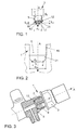
- the fuel supply line 1, as shown in Fig. 2 The, in particular designed as an internal bore, receptacle 5, in which with respect to the axial direction A, an internal thread 19 is introduced.
- the internal thread 19 merges into a bore 21 whose diameter d G is initially constant in the axial direction A and then decreases toward a bore base diameter d I.
- a diameter in the range between the diameter d G of the bore 21 and the bore base diameter d I is denoted by d K.
- the in the Fig. 3 and 4 shown installation position shows the pressure sensor 3 in the receptacle 5 of the high-pressure fuel line 1.
- the pressure sensor 3 is screwed in the axial direction A via an external thread 9 on the nozzle 7 in the internal thread 19 of the receptacle 5.
- the receptacle 5 of the high-pressure fuel line 1 has to the internal thread 19 spaced within the bore 21 a reduction in the diameter.
- the diameter of the bore d G decreases toward a bore base diameter d I , wherein the average diameter d K is at the contact point between the bulge 23 and the bore 21.
- the bulge 23 is plastically deformed in the installation position shown, whereby internal stresses are induced in the components.
- the sealing element 13 is disposed within the projection 11, wherein the radially outer annular surface 17 of the sealing element 13 is in contact with the radially inner annular surface 15 of the projection 11 of the nozzle 7 of the pressure sensor 3. In the axial direction, the sealing element is further compressed between the bore bottom of the receptacle 5 and the nozzle 7, so that the sealing ring 13 is elastically deformed and thereby mechanically fretted.
- the induced by the deformation of the bulge 23 and the sealing element 13 residual stresses counteract the high pressures occurring during operation, so that the burden on the components is significantly reduced.
- Fig. 5 shows a further embodiment of the radial expression 23 of the attachment part 3, wherein the radial expression 23 is conically shaped in this embodiment.
- the diameter d S of the expression 23 becomes larger with respect to the axial direction A from the diameter of the constriction 12 to the outside, so that a counter-conical surface to the bore 21 according to Fig. 2 results.
Abstract
Die Erfindung betrifft eine Dichtungsanordnung für eine Kraftstoffzuleitung (1), insbesondere eine Kraftstoffverteilerleitung für mehrere Einspritzventile einer Brennkraftmaschine, welche mindestens ein ringförmiges Dichtelement (13) aufweist, welches ein oder mehrere Anbauteile (3) bei den im Betrieb auftretenden sehr hohen Drücken besonders wirksam gegen die Umgebung abdichtet. Der Bohrungsgrunddurchmesser ( d K ) einer Aufnahme (5) an der Kraftstoffzuleitung (1) weist innerhalb seiner Innengewindebohrung (19) eine konisch zulaufende Fläche auf, die in Kombination mit einer radialen Ausprägung (23) an dem Anbauteil (3) eine radiale Abstützung des Dichtelementes (13) erzielt.The invention relates to a sealing arrangement for a fuel supply line (1), in particular a fuel distributor line for a plurality of injection valves of an internal combustion engine, which has at least one annular sealing element (13) which is particularly effective against one or more attachments (3) at the very high pressures occurring during operation the environment seals. The bore base diameter (d K) of a receptacle (5) on the fuel supply line (1) has within its internally threaded bore (19) a tapered surface, which in combination with a radial expression (23) on the attachment (3) a radial support of the Sealing element (13) achieved.
Description
Die Erfindung betrifft eine Dichtungsanordnung für eine Kraftstoffzuleitung, insbesondere eine Verteilerleitung für mehrere Einspritzventile einer Brennkraftmaschine, welche mindestens ein ringförmiges Dichtelement aufweist.The invention relates to a sealing arrangement for a fuel supply line, in particular a distributor line for a plurality of injection valves of an internal combustion engine, which has at least one annular sealing element.
Es ist aus
Weiterhin ist aus
Das Hauptaugenmerk der heutigen Entwicklung von Verbrennungsmotoren und deren Komponenten, bspw. von Kraftstoffhochdruckverteilerleitungen, liegt in der Verbesserung der Motorlaufeigenschaften sowie einer Reduzierung der Partikelemissionen und Stickoxidbildung. Durch den unter Druck stehenden eingespritzten Kraftstoff in den Brennraum wird der Kraftstoff sehr fein zerstäubt, was zu einer vollständigeren schnelleren Verbrennung und dadurch zu einer geringeren Partikelmasse im Abgas führt. Je höher der Druck an einer Kraftstoffhochdruckverteilerleiste desto feiner kann der Kraftstoff zerstäubt und damit die Partikelemissionen reduziert werden. In einer Kraftstoffhochdruckverteilerleiste der sogenannten ersten Generation lagen die erwarteten Einspritzdrücke bereits bei etwa 1350 bar. Bei höheren Drücken der heutigen Kraftstoffhochdruckverteilerleitungen ist die Zuverlässigkeit der Rohrverschraubung aus dieser Schrift bei weitem nicht mehr gegeben.The main focus of today's development of internal combustion engines and their components, for example. Of high-pressure fuel rail lines, lies in the improvement of the engine running characteristics and a reduction of particulate emissions and nitrogen oxide formation. Due to the pressurized injected fuel into the combustion chamber, the fuel is very finely atomized, resulting in a more complete faster combustion and thereby a lower particle mass in the exhaust gas leads. The higher the pressure at a high-pressure fuel rail, the finer the fuel can be atomized and thus the particle emissions reduced. In a high-pressure fuel rail of the so-called first generation, the expected injection pressures were already around 1350 bar. At higher pressures of today's high-pressure fuel rail, the reliability of the pipe fitting from this document is nowhere near.
Der begrenzende Faktor für die Bereitstellung der gewünschten hohen Einspritzdrücke liegt in der Abdichtung der Verbindungen zwischen den einzelnen Hochdruckbauteilen gegen die Umgebung. Neben der Abdichtung des Verteilerleiste an die Kraftstoffleitungen bzw. die Injektoren muss auch ein Drucksensor, welcher zu jeder Zeit den aktuellen Druck mit ausreichender Genauigkeit (max. ±2% im Hauptbetriebsbereich) als Spannungssignal an die Motorsteuerung meldet, gegen die Umgebung abgedichtet werden. Eine Leckage am Drucksensor führt zu einer ungenauen Rückmeldung an das Motorsteuergerät und so zu einer nicht am optimalen Betriebspunkt stattfindenden Verbrennung und somit zu einer höheren Partikel- und Stickstoffemission. Somit kann auch die Betriebssicherheit nicht mehr vollständig gewährleistet werden.The limiting factor for providing the desired high injection pressures lies in the sealing of the connections between the individual high-pressure components against the environment. In addition to the sealing of the distributor strip to the fuel lines or the injectors, a pressure sensor which reports the current pressure with sufficient accuracy (maximum ± 2% in the main operating range) as a voltage signal to the engine control system at all times must also be sealed against the environment. A leakage at the pressure sensor leads to an inaccurate feedback to the engine control unit and thus to a combustion not taking place at the optimum operating point and thus to a higher particle and nitrogen emission. Thus, the reliability can not be completely guaranteed.
Die Festigkeiten der Werkstoffe der im Allgemeinen bekannten Abdichtungen, sogenannte Beißkanten von Anbauteilen, reichen nicht mehr vollständig an die Festigkeiten des höchstfesten Materials der Kraftstoffzuleitungen heran. Im Betrieb bei einer Belastung der Beißkante von ca. 3000 bar und mehr verliert die Beißkante den Kontakt, weswegen der Werkstoff deutlich härter gewählt werden muss, als das Grundmaterial der Kraftstoffzuleitung. Dies dient ebenfalls dem Ausgleichen etwaiger geometrischer Ungenauigkeiten, die aus dem Herstellprozess bedingt sind.
Die bisher eingesetzten Dichtelemente, vorzugsweise Dichtscheiben, stellen hierbei hinsichtlich Maßhaltigkeit und Zentrierbarkeit eine Herausforderung dar. Weiterhin führt die relative Weichheit der Dichtscheiben zu unkontrollierbaren und unzulässig hohen radialen und axialen Verformungen.
Die in dieser konventionellen Anordnung auftretenden sehr hohen Drücke bei der Autofrettage der sehr weichen Dichtscheibe, können zu Mikrorissen an der Oberfläche der Innenbohrung führen, sodass die Dauerhaltbarkeit der Bauteile gesenkt ist und die Dichtigkeit unter Umständen nicht mehr vollständig gewährleistet ist, somit muss bei der Herstellung der Dichtscheiben in einem aufwendigen Herstellungsprozess sehr genau gearbeitet werden.The strength of the materials of the generally known seals, so-called Beißkanten of attachments, no longer fully enough to the strength of the ultrahigh-strength material of the fuel supply lines zoom. In operation with a loading of the biting edge of about 3000 bar and more, the biting edge loses contact, which is why the material must be chosen significantly harder than the base material of the fuel supply line. This also serves to compensate for any geometric inaccuracies that are due to the manufacturing process.
The sealing elements used hitherto, preferably sealing disks, represent a challenge in terms of dimensional stability and centerability. Furthermore, the relative softness of the sealing disks leads to uncontrollable and impermissibly high radial and axial deformations.
The very high pressures in the autofrettage of the very soft sealing disc, which occur in this conventional arrangement, can lead to microcracks on the surface of the inner bore, so that the durability of the components is lowered and the tightness may no longer be completely guaranteed the sealing discs are worked very carefully in a complex manufacturing process.
Der Erfindung liegt die Aufgabe zugrunde eine Dichtungsanordnung einer Kraftstoffzuleitung, insbesondere eine Kraftstoffhochdruckverteilerleitung, für steigende Einspritzdruckanforderungen derart zu verbessern, dass die Anbauteile, beispielsweise ein Drucksensor, wirksam gegen die Umgebung abgedichtet sind.The invention has for its object a sealing arrangement of a fuel supply line, in particular a high-pressure fuel rail to improve for increasing injection pressure requirements such that the attachments, such as a pressure sensor, are effectively sealed from the environment.
Die Aufgabe wird erfindungsgemäß durch die Merkmale des Patentanspruchs 1 gelöst.
Die erfindungsgemäße Dichtungsanordnung weist eine Aufnahme eines Anbauteiles an einer Kraftstoffzuleitung, insbesondere einer Kraftstoffhochdruckverteilerleitung, und ein Anbauteil, insbesondere einen Drucksensor, sowie ein Dichtelement auf. Die Aufnahme des Anbauteiles weist eine Bohrung auf, die am innersten Ende konisch zuläuft, sodass sich Ihre Grundfläche allmählich verringert.
Das Anbauteil weist in seiner Axialrichtung einen Stutzen und ein, an dessen äußersten Ende befindlichen, radial umlaufenden axialen Vorsprung auf. Innerhalb des Vorsprungs und daran radial anliegend ist ein Dichtelement angeordnet. Durch die Anlage des Dichtelementes an dem Vorsprung kann dieses nicht nach außen hin ausweichen. In vorteilhafter Weise ist das Dichtelement in Axialrichtung länger als der Vorsprung des Anbauteiles. Das Dichtelement kann somit im Betrieb nicht arbeiten bzw. nach außen ausweichen und stützt sich in Umfangsrichtung an dem Vorsprung ab.
Der konisch zulaufende Bohrungsgrund der Aufnahme steht mit dem Anbauteil in Kontakt, vorzugsweise unter einer Vorspannkraft von 30 bis 40 kN sodass sich der Vorsprung an der Aufnahme abstützt. Eine vorteilhafte Abdichtung wird erreicht, wenn die Aufnahme und das Anbauteil derart angeordnet sind, dass im Zusammenbau der Durchmesser des Vorsprunges des Anbauteiles kleiner ist, als der Durchmesser der Aufnahme an der Stelle, an der der Vorsprung anliegt.
Es ergibt sich eine dichtende Anlage, da sich das Dichtelement gegen den Vorsprung und im Weiteren der Vorsprung gegen die Aufnahme abstützt und dichtend anliegt. Es kann somit auf eine zusätzliche herkömmliche Dichtscheibe verzichtet werden.The object is achieved by the features of
The seal assembly according to the invention has a receptacle of an attachment to a fuel supply line, in particular a high-pressure fuel rail, and an attachment, in particular a pressure sensor, and a sealing element. The attachment has a hole that tapers at the innermost end, gradually reducing your footprint.
The attachment has in its axial direction a nozzle and a, located at the extreme end, radially encircling axial projection. Within the projection and radially adjacent thereto, a sealing element is arranged. By the system of the sealing element on the projection, this can not escape to the outside. Advantageously, the sealing element in the axial direction is longer than the projection of the attachment. The sealing element can thus not work during operation or to escape to the outside and is supported in the circumferential direction of the projection.
The tapered bore bottom of the receptacle is in contact with the attachment, preferably under a biasing force of 30 to 40 kN so that the projection is supported on the receptacle. An advantageous seal is achieved when the receptacle and the attachment are arranged such that in the assembly of the diameter of the projection of the attachment part is smaller than the diameter of the receptacle at the point at which rests the projection.
The result is a sealing contact, since the sealing element is supported against the projection and in the further the projection against the receptacle and sealingly. It can thus be dispensed with an additional conventional sealing disc.
Die erfindungsgemäße Dichtungsanordnung kann durch die kennzeichnenden Merkmale der Unteransprüche ausgestaltet werden, womit die Ausgestaltungsmöglichkeiten jedoch nicht erschöpft sind.The sealing arrangement according to the invention can be configured by the characterizing features of the subclaims, with which, however, the design options are not exhausted.
Die Erfindung beruht weiterhin auf der Erkenntnis der Autofrettage, wobei die Dauerfestigkeit der erfindungsgemäßen Bauteile erhöht wird. In einer vorteilhaften Weiterbildung induziert die Kombination der erwünschten plastischen Verformung des Vorsprungs des Anbauteiles mit der elastischen radialen und axialen Verformung des Dichtelementes in dem Dichtelement Druckeigenspannungen. Diese Druckeigenspannungen wirken den im Betrieb der Kraftstoffzuleitung an der Randfaser auftretenden Zugspannungsspitzen bzw. Pulsationen im Dichtelement entgegen, sodass die Zugspannungsspitzen zumindest teilweise kompensiert werden.The invention is further based on the recognition of autofrettage, wherein the fatigue strength of the components according to the invention is increased. In an advantageous development, the combination induces the desired plastic deformation of the projection of the attachment part with the elastic radial and axial deformation of the sealing element in the sealing element Compressive stresses. These residual compressive stresses counteract the tensile stress peaks or pulsations occurring in the sealing element during operation of the fuel supply line at the edge fiber, so that the tensile stress peaks are at least partially compensated.
In vorteilhafter Weise weist der Stutzen des Anbauteiles ein Außengewinde und die Aufnahme ein Innengewinde auf, sodass das Anbauteil mit der Aufnahme verschraubbar ist. Die erfindungsgemäße Ausgestaltung wirkt einer Verformung des Dichtelementes während der Verschraubung entgegen. Die tragende Außengewindestruktur unterstützt in vorteilhafter Weise den Autofrettageeffekt und ist eine sehr einfache und kostengünstige Herstell- und Montagemöglichkeit. Weiter ist es vorteilhaft, dass der Stutzen in seiner Axialrichtung kürzer ist als die Aufnahme, da hierbei eine Doppelpassung des Stutzens und so ein Ausgleichen der gewollten induzierten Eigenspannungen vermieden wird.Advantageously, the neck of the attachment has an external thread and the receptacle has an internal thread, so that the attachment can be screwed to the receptacle. The embodiment according to the invention counteracts deformation of the sealing element during the screwing. The supporting external thread structure advantageously supports the autofrettage effect and is a very simple and cost-effective production and assembly option. Further, it is advantageous that the neck is shorter in its axial direction than the receptacle, since in this case a double fit of the neck and thus a balancing of the desired induced residual stresses is avoided.
In einer vorteilhaften erfindungsgemäßen Erweiterung erstreckt sich die auf dem Stutzen eingebrachte Außengewindestruktur nicht über die gesamte axiale Länge des Stutzen, sondern ist nur in den oberen Teil eingebracht und so zu dem Vorsprung beabstandet.In an advantageous expansion according to the invention introduced on the neck external thread structure does not extend over the entire axial length of the nozzle, but is introduced only in the upper part and thus spaced from the projection.
Der Stutzen des Anbauteiles kann vorteilhaft an seinem äußeren Ende und zu dem Außengewinde beabstandet eine radiale Ausprägung, insbesondere eine radiale Wulst, zur wirkungsvolleren Abdichtung aufweisen. Die radiale Wulst ist idealerweise ringförmig und einteilig mit dem Stutzen ausgebildet, was den Herstellaufwand erheblich reduziert und die Dichtigkeit der Anordnung verbessert.The nozzle of the attachment can advantageously at its outer end and the external thread spaced a radial expression, in particular a radial bead, have for more effective sealing. The radial bead is ideally annular and integrally formed with the neck, which significantly reduces the manufacturing effort and improves the tightness of the arrangement.
Eine alternative Ausführungsform sieht vor, dass die radiale Ausprägung des Stutzens als konische Fläche entgegengesetzt zu der konisch Fläche der Aufnahme ausgeführt ist. Der Durchmesser der radialen Ausprägung nimmt zum äußeren Ende des Stutzens hin zu, während der Durchmesser der Aufnahme weiterhin konischen nach innen abnimmt.An alternative embodiment provides that the radial extent of the neck is designed as a conical surface opposite to the conical surface of the receptacle. The diameter of the radial shape increases toward the outer end of the nozzle, while the diameter of the recording continues to decrease conically inwards.
In einer vorteilhaften Weiterbildung der Erfindung liegt die Zugfestigkeit der Kraftstoffhochdruckleitung, mit vorzugsweise etwa 1350 N/mm2, oberhalb der Zugfestigkeit des Anbauteils, die vorzugsweise bei etwa 1200 N/mm2 liegt. Dies kann über unterschiedliche Werkstoffauswahl erreicht werden. Vorteilhafter Weise wird für die Kraftstoffhochdruckleitung eine Stahllegierung für höherfeste Schmiedebauteile gewählt.In an advantageous embodiment of the invention, the tensile strength of the high-pressure fuel line, preferably about 1350 N / mm 2 , above the tensile strength of the attachment, which is preferably about 1200 N / mm 2 . This can be achieved by different material selection. Advantageously, a steel alloy for higher strength forging components is selected for the high-pressure fuel line.
Die Erfindung lässt zahlreiche Ausführungsformen zu, die ebenfalls unter den Schutzbereich fallen. Zur weiteren Verdeutlichung ihres Grundprinzips ist eine bevorzugte Ausführungsform in den Figuren dargestellt und wird nachfolgend beschrieben.The invention allows for numerous embodiments which also fall within the scope of protection. To further clarify its basic principle, a preferred embodiment is shown in the figures and will be described below.
Es zeigen
- Fig. 1
- eine erfindungsgemäße Ausführungsform eines Anbauteiles
- Fig. 2
- eine erfindungsgemäße Ausführungsform einer Hochdruckseite einer Kraftstoffzuleitung
- Fig. 3
- schematische Darstellung eines Zusammenbaus des Anbauteiles aus
Fig. 1 und der Kraftstoffzuleitung ausFig. 2 - Fig. 4
- das bevorzugte Ausführungsbeispiel aus
Fig. 3 in einer Detailansicht - Fig. 5
- ein weiteres erfindungsgemäßes Ausführungsbeispiel des Anbauteiles
- Fig. 1
- an embodiment of an attachment according to the invention
- Fig. 2
- an embodiment of the invention a high pressure side of a fuel supply line
- Fig. 3
- schematic representation of an assembly of the attachment from
Fig. 1 and the fuel supplyFig. 2 - Fig. 4
- the preferred embodiment
Fig. 3 in a detailed view - Fig. 5
- another inventive embodiment of the attachment
Gemäß einer in den
Die Beschaffenheit dieser Bestandteile und ihr Zusammenwirken werden nachfolgend genauer beschrieben:
- An
den Drucksensor 3, gemäßFig. 1 , ist in Bezug auf die AxialrichtungA ein Stutzen 7 angeformt.Auf dem Stutzen 7 ist in Bezug auf die Axialrichtung A im oberenTeil ein Außengewinde 9 angeformt, sowie daran anschließend eine Einschnürung 12 mit dem Durchmesser dE und ein ringförmiger axialer Vorsprung 11.Der Vorsprung 11 weist weiterhin eine radiale Ausprägung 23, insbesondere als Stauchwulst ausgebildet, mit einem Durchmesser dS und eine innere Ringfläche 15 einer Länge LS auf, welche teilweise in Kontakt mit einer äußeren Ringfläche 17 aufweisend eine Länge LD des Dichtelementes 13 steht. Die Abmessung LD des Dichtelementes 13 ist in Axialrichtung A größer, als die Länge der inneren Ringfläche 15 des Vorsprungs LS . Der Durchmesser dS der Stauchwulst 23 ist vorzugsweise kleiner als der Außengewindedurchmesser desAußengewindes 9.
The nature of these components and their interaction are described in more detail below:
- To the
pressure sensor 3, according toFig. 1 , Anozzle 7 is formed with respect to the axial direction A. On theneck 7, anexternal thread 9 is formed in relation to the axial direction A in the upper part, and thereafter aconstriction 12 with the diameter d E and an annularaxial projection 11. Theprojection 11 further has aradial shape 23, in particular as Stauchwulst formed, with a diameter d S and an innerannular surface 15 of a length L S , which is partially in contact with an outerannular surface 17 having a length L D of the sealingelement 13. The dimension L D of the sealingelement 13 is greater in the axial direction A than the length of the innerannular surface 15 of the projection L S. The diameter d S of thebulge 23 is preferably smaller than the external thread diameter of theexternal thread 9.
Die Kraftstoffzuleitung 1, wie dargestellt in
Die in den
Das Dichtelement 13 ist innerhalb des Vorsprungs 11 angeordnet, wobei sich die radial äußere Ringfläche 17 des Dichtelementes 13 mit der radial inneren Ringfläche 15 des Vorsprungs 11 des Stutzen 7 des Drucksensors 3 in Kontakt befindet. In Axialrichtung ist das Dichtelement weiter zwischen dem Bohrungsgrund der Aufnahme 5 und dem Stutzen 7 verpresst, sodass der Dichtring 13 elastisch verformt und dadurch mechanisch frettiert ist.
Die durch die Verformung der Stauchwulst 23 und des Dichtelements 13 induzierten Eigenspannungen wirken den im Betrieb auftretenden hohen Drücken entgegen, sodass die Belastung für die Bauteile deutlich reduziert wird.The in the
The sealing
The induced by the deformation of the
Die in den Fig. dargestellten Ausführungsformen sind nicht abschließend. Es sind weitere Ausführungsformen denkbar.The embodiments shown in the figures are not exhaustive. There are further embodiments conceivable.
- 11
- KraftstoffzuleitungFuel supply
- 33
- Drucksensorpressure sensor
- 55
- Aufnahmeadmission
- 77
- StutzenSupport
- 99
- Außengewindeexternal thread
- 1111
- Vorsprunghead Start
- 1212
- Einschnürungconstriction
- 1313
- Dichtelementsealing element
- 1515
- innere Ringflächeinner ring surface
- 1717
- äußere Ringflächeouter ring surface
- 1919
- Innengewindeinner thread
- 2121
- Bohrungdrilling
- 2323
- radiale Ausprägung/ Stauchwulstradial expression / upset bead
- dK d K
- Durchmesser dI ≤ dK ≤ dG Diameter d I ≦ d K ≦ d G
- dS d S
- Durchmesser radiale Ausprägung/StauchwulstDiameter radial expression / upset bead
- dI d i
- BohrungsgrunddurchmesserHole bottom diameter
- dG d G
- Durchmesser BohrungDiameter bore
- dE d E
- Durchmesser EinschnürungDiameter constriction
- LS L S
- Länge radiale AusprägungLength radial characteristic
- LD L D
- Länge DichtelementLength of sealing element
Claims (8)
Applications Claiming Priority (1)
| Application Number | Priority Date | Filing Date | Title |
|---|---|---|---|
| DE102015216150.1A DE102015216150A1 (en) | 2015-08-25 | 2015-08-25 | Sealing arrangement for a fuel supply line |
Publications (2)
| Publication Number | Publication Date |
|---|---|
| EP3135898A1 true EP3135898A1 (en) | 2017-03-01 |
| EP3135898B1 EP3135898B1 (en) | 2018-04-18 |
Family
ID=56551140
Family Applications (1)
| Application Number | Title | Priority Date | Filing Date |
|---|---|---|---|
| EP16177871.7A Active EP3135898B1 (en) | 2015-08-25 | 2016-07-05 | Sealing assembly for a fuel line |
Country Status (2)
| Country | Link |
|---|---|
| EP (1) | EP3135898B1 (en) |
| DE (1) | DE102015216150A1 (en) |
Cited By (1)
| Publication number | Priority date | Publication date | Assignee | Title |
|---|---|---|---|---|
| CN112771268A (en) * | 2018-10-01 | 2021-05-07 | 罗伯特·博世有限公司 | High-pressure fuel pump with an attached nozzle |
Citations (5)
| Publication number | Priority date | Publication date | Assignee | Title |
|---|---|---|---|---|
| DE2817438A1 (en) | 1978-04-21 | 1979-10-25 | Cohnen Gmbh & Co | IC engine fuel injection line joint - has pipe end forced against washer inside nipple by tightening inner sleeve |
| DE4413863A1 (en) | 1994-04-21 | 1995-10-26 | Parker Praedifa Gmbh | Sealing arrangement for injectors on fuel supply lines |
| DE19547890A1 (en) * | 1995-12-21 | 1997-06-26 | Bosch Gmbh Robert | Sealing unit for a fuel pressure sensor |
| US5855397A (en) * | 1997-04-02 | 1999-01-05 | Cummins Engine Company, Inc. | High-pressure sealable connector for a pressure sensor |
| EP1316720A1 (en) * | 2001-11-29 | 2003-06-04 | Denso Corporation | Common rail fuel injection system |
Family Cites Families (4)
| Publication number | Priority date | Publication date | Assignee | Title |
|---|---|---|---|---|
| US5720505A (en) * | 1995-08-09 | 1998-02-24 | Fujikin Incorporated | Pipe joint |
| DE19729392C2 (en) * | 1997-07-09 | 1999-05-06 | Siemens Ag | Fuel storage with seal |
| DE102009028262A1 (en) * | 2009-08-05 | 2011-02-10 | Robert Bosch Gmbh | High pressure loaded component i.e. fuel injector, pressure resistance increasing method for self-ignition internal combustion engine, involves producing autofrettage pressure of seven kilo bars inside assembly group |
| DE102010029052A1 (en) * | 2010-05-18 | 2011-11-24 | Robert Bosch Gmbh | Fuel distributor and its use |
-
2015
- 2015-08-25 DE DE102015216150.1A patent/DE102015216150A1/en not_active Withdrawn
-
2016
- 2016-07-05 EP EP16177871.7A patent/EP3135898B1/en active Active
Patent Citations (5)
| Publication number | Priority date | Publication date | Assignee | Title |
|---|---|---|---|---|
| DE2817438A1 (en) | 1978-04-21 | 1979-10-25 | Cohnen Gmbh & Co | IC engine fuel injection line joint - has pipe end forced against washer inside nipple by tightening inner sleeve |
| DE4413863A1 (en) | 1994-04-21 | 1995-10-26 | Parker Praedifa Gmbh | Sealing arrangement for injectors on fuel supply lines |
| DE19547890A1 (en) * | 1995-12-21 | 1997-06-26 | Bosch Gmbh Robert | Sealing unit for a fuel pressure sensor |
| US5855397A (en) * | 1997-04-02 | 1999-01-05 | Cummins Engine Company, Inc. | High-pressure sealable connector for a pressure sensor |
| EP1316720A1 (en) * | 2001-11-29 | 2003-06-04 | Denso Corporation | Common rail fuel injection system |
Cited By (1)
| Publication number | Priority date | Publication date | Assignee | Title |
|---|---|---|---|---|
| CN112771268A (en) * | 2018-10-01 | 2021-05-07 | 罗伯特·博世有限公司 | High-pressure fuel pump with an attached nozzle |
Also Published As
| Publication number | Publication date |
|---|---|
| EP3135898B1 (en) | 2018-04-18 |
| DE102015216150A1 (en) | 2017-03-02 |
Similar Documents
| Publication | Publication Date | Title |
|---|---|---|
| EP1366284B1 (en) | Sealing device a fuel injection valve | |
| EP2126427B1 (en) | Non-return valve and injector with hydraulic booster and non-return valve | |
| DE102009000285A1 (en) | Fuel injector as well as internal combustion engine with fuel injector | |
| EP1774217A1 (en) | Connection for high-pressure media conduits | |
| EP1454057B1 (en) | Valve for the control of fluids | |
| EP3245433B1 (en) | Connection arrangement for establishing a hydraulic connection | |
| EP3135898B1 (en) | Sealing assembly for a fuel line | |
| DE102012211283A1 (en) | Leakage and slip reduced valve | |
| EP1430218B1 (en) | Valve, in particular fuel injection valve | |
| DE102020203650A1 (en) | Component for an injection system and injection system for mixture-compressing, externally ignited internal combustion engines | |
| DE102015209263B3 (en) | High-pressure connection device, high-pressure fuel pump and method for producing a high-pressure connection device for a high-pressure fuel pump | |
| EP1241348B1 (en) | High pressure connection for fuel injection system | |
| DE102017218002A1 (en) | Decoupling element for a fuel injection device | |
| WO2015172950A1 (en) | Fuel feed system to a fuel injector, and fuel injector | |
| EP1710429A1 (en) | Valve for control of an injection valve of an internal combustion engine | |
| EP1319128B1 (en) | Fuel injection valve for internal combustion engines | |
| EP0716226A2 (en) | Fuel injection valve for internal combustion engines | |
| EP0513020B1 (en) | Fuel-injection nozzle with an overflow-oil line | |
| DE102012012422A1 (en) | Fastening arrangement for fastening fuel line to injector, has passage opening that is conically formed in longitudinal extension direction of fuel line in subarea | |
| EP3380716B1 (en) | Fuel injector comprising a sealing element | |
| DE102016200758B4 (en) | High-pressure fuel pump for a fuel injection system of an internal combustion engine and sealing arrangement | |
| DE4431740A1 (en) | Pressure valve | |
| DE102022000302A1 (en) | Cylinder head for an internal combustion engine with a combustion chamber and the use of a sealing sleeve for sealing a cylinder head | |
| WO2022200059A1 (en) | Sealing element | |
| DE102021200868A1 (en) | Control valve for an injection valve, injection valve with control valve |
Legal Events
| Date | Code | Title | Description |
|---|---|---|---|
| PUAI | Public reference made under article 153(3) epc to a published international application that has entered the european phase |
Free format text: ORIGINAL CODE: 0009012 |
|
| AK | Designated contracting states |
Kind code of ref document: A1 Designated state(s): AL AT BE BG CH CY CZ DE DK EE ES FI FR GB GR HR HU IE IS IT LI LT LU LV MC MK MT NL NO PL PT RO RS SE SI SK SM TR |
|
| AX | Request for extension of the european patent |
Extension state: BA ME |
|
| 17P | Request for examination filed |
Effective date: 20170901 |
|
| RBV | Designated contracting states (corrected) |
Designated state(s): AL AT BE BG CH CY CZ DE DK EE ES FI FR GB GR HR HU IE IS IT LI LT LU LV MC MK MT NL NO PL PT RO RS SE SI SK SM TR |
|
| GRAP | Despatch of communication of intention to grant a patent |
Free format text: ORIGINAL CODE: EPIDOSNIGR1 |
|
| RIC1 | Information provided on ipc code assigned before grant |
Ipc: F16L 15/00 20060101ALI20171025BHEP Ipc: F02M 55/00 20060101AFI20171025BHEP Ipc: G01L 1/00 20060101ALI20171025BHEP Ipc: F16L 21/04 20060101ALI20171025BHEP |
|
| INTG | Intention to grant announced |
Effective date: 20171122 |
|
| GRAS | Grant fee paid |
Free format text: ORIGINAL CODE: EPIDOSNIGR3 |
|
| GRAA | (expected) grant |
Free format text: ORIGINAL CODE: 0009210 |
|
| AK | Designated contracting states |
Kind code of ref document: B1 Designated state(s): AL AT BE BG CH CY CZ DE DK EE ES FI FR GB GR HR HU IE IS IT LI LT LU LV MC MK MT NL NO PL PT RO RS SE SI SK SM TR |
|
| REG | Reference to a national code |
Ref country code: GB Ref legal event code: FG4D Free format text: NOT ENGLISH |
|
| REG | Reference to a national code |
Ref country code: CH Ref legal event code: EP |
|
| REG | Reference to a national code |
Ref country code: AT Ref legal event code: REF Ref document number: 990759 Country of ref document: AT Kind code of ref document: T Effective date: 20180515 |
|
| REG | Reference to a national code |
Ref country code: IE Ref legal event code: FG4D Free format text: LANGUAGE OF EP DOCUMENT: GERMAN |
|
| REG | Reference to a national code |
Ref country code: DE Ref legal event code: R096 Ref document number: 502016000907 Country of ref document: DE |
|
| REG | Reference to a national code |
Ref country code: FR Ref legal event code: PLFP Year of fee payment: 3 |
|
| REG | Reference to a national code |
Ref country code: NL Ref legal event code: MP Effective date: 20180418 |
|
| REG | Reference to a national code |
Ref country code: LT Ref legal event code: MG4D |
|
| PG25 | Lapsed in a contracting state [announced via postgrant information from national office to epo] |
Ref country code: NL Free format text: LAPSE BECAUSE OF FAILURE TO SUBMIT A TRANSLATION OF THE DESCRIPTION OR TO PAY THE FEE WITHIN THE PRESCRIBED TIME-LIMIT Effective date: 20180418 |
|
| PG25 | Lapsed in a contracting state [announced via postgrant information from national office to epo] |
Ref country code: ES Free format text: LAPSE BECAUSE OF FAILURE TO SUBMIT A TRANSLATION OF THE DESCRIPTION OR TO PAY THE FEE WITHIN THE PRESCRIBED TIME-LIMIT Effective date: 20180418 Ref country code: LT Free format text: LAPSE BECAUSE OF FAILURE TO SUBMIT A TRANSLATION OF THE DESCRIPTION OR TO PAY THE FEE WITHIN THE PRESCRIBED TIME-LIMIT Effective date: 20180418 Ref country code: PL Free format text: LAPSE BECAUSE OF FAILURE TO SUBMIT A TRANSLATION OF THE DESCRIPTION OR TO PAY THE FEE WITHIN THE PRESCRIBED TIME-LIMIT Effective date: 20180418 Ref country code: FI Free format text: LAPSE BECAUSE OF FAILURE TO SUBMIT A TRANSLATION OF THE DESCRIPTION OR TO PAY THE FEE WITHIN THE PRESCRIBED TIME-LIMIT Effective date: 20180418 Ref country code: NO Free format text: LAPSE BECAUSE OF FAILURE TO SUBMIT A TRANSLATION OF THE DESCRIPTION OR TO PAY THE FEE WITHIN THE PRESCRIBED TIME-LIMIT Effective date: 20180718 Ref country code: BG Free format text: LAPSE BECAUSE OF FAILURE TO SUBMIT A TRANSLATION OF THE DESCRIPTION OR TO PAY THE FEE WITHIN THE PRESCRIBED TIME-LIMIT Effective date: 20180718 Ref country code: SE Free format text: LAPSE BECAUSE OF FAILURE TO SUBMIT A TRANSLATION OF THE DESCRIPTION OR TO PAY THE FEE WITHIN THE PRESCRIBED TIME-LIMIT Effective date: 20180418 Ref country code: AL Free format text: LAPSE BECAUSE OF FAILURE TO SUBMIT A TRANSLATION OF THE DESCRIPTION OR TO PAY THE FEE WITHIN THE PRESCRIBED TIME-LIMIT Effective date: 20180418 |
|
| PG25 | Lapsed in a contracting state [announced via postgrant information from national office to epo] |
Ref country code: RS Free format text: LAPSE BECAUSE OF FAILURE TO SUBMIT A TRANSLATION OF THE DESCRIPTION OR TO PAY THE FEE WITHIN THE PRESCRIBED TIME-LIMIT Effective date: 20180418 Ref country code: GR Free format text: LAPSE BECAUSE OF FAILURE TO SUBMIT A TRANSLATION OF THE DESCRIPTION OR TO PAY THE FEE WITHIN THE PRESCRIBED TIME-LIMIT Effective date: 20180719 Ref country code: HR Free format text: LAPSE BECAUSE OF FAILURE TO SUBMIT A TRANSLATION OF THE DESCRIPTION OR TO PAY THE FEE WITHIN THE PRESCRIBED TIME-LIMIT Effective date: 20180418 Ref country code: LV Free format text: LAPSE BECAUSE OF FAILURE TO SUBMIT A TRANSLATION OF THE DESCRIPTION OR TO PAY THE FEE WITHIN THE PRESCRIBED TIME-LIMIT Effective date: 20180418 |
|
| REG | Reference to a national code |
Ref country code: DE Ref legal event code: R097 Ref document number: 502016000907 Country of ref document: DE |
|
| PG25 | Lapsed in a contracting state [announced via postgrant information from national office to epo] |
Ref country code: SK Free format text: LAPSE BECAUSE OF FAILURE TO SUBMIT A TRANSLATION OF THE DESCRIPTION OR TO PAY THE FEE WITHIN THE PRESCRIBED TIME-LIMIT Effective date: 20180418 Ref country code: RO Free format text: LAPSE BECAUSE OF FAILURE TO SUBMIT A TRANSLATION OF THE DESCRIPTION OR TO PAY THE FEE WITHIN THE PRESCRIBED TIME-LIMIT Effective date: 20180418 Ref country code: CZ Free format text: LAPSE BECAUSE OF FAILURE TO SUBMIT A TRANSLATION OF THE DESCRIPTION OR TO PAY THE FEE WITHIN THE PRESCRIBED TIME-LIMIT Effective date: 20180418 Ref country code: DK Free format text: LAPSE BECAUSE OF FAILURE TO SUBMIT A TRANSLATION OF THE DESCRIPTION OR TO PAY THE FEE WITHIN THE PRESCRIBED TIME-LIMIT Effective date: 20180418 Ref country code: EE Free format text: LAPSE BECAUSE OF FAILURE TO SUBMIT A TRANSLATION OF THE DESCRIPTION OR TO PAY THE FEE WITHIN THE PRESCRIBED TIME-LIMIT Effective date: 20180418 |
|
| PLBE | No opposition filed within time limit |
Free format text: ORIGINAL CODE: 0009261 |
|
| STAA | Information on the status of an ep patent application or granted ep patent |
Free format text: STATUS: NO OPPOSITION FILED WITHIN TIME LIMIT |
|
| PG25 | Lapsed in a contracting state [announced via postgrant information from national office to epo] |
Ref country code: SM Free format text: LAPSE BECAUSE OF FAILURE TO SUBMIT A TRANSLATION OF THE DESCRIPTION OR TO PAY THE FEE WITHIN THE PRESCRIBED TIME-LIMIT Effective date: 20180418 Ref country code: IT Free format text: LAPSE BECAUSE OF FAILURE TO SUBMIT A TRANSLATION OF THE DESCRIPTION OR TO PAY THE FEE WITHIN THE PRESCRIBED TIME-LIMIT Effective date: 20180418 |
|
| 26N | No opposition filed |
Effective date: 20190121 |
|
| PG25 | Lapsed in a contracting state [announced via postgrant information from national office to epo] |
Ref country code: LU Free format text: LAPSE BECAUSE OF NON-PAYMENT OF DUE FEES Effective date: 20180705 Ref country code: MC Free format text: LAPSE BECAUSE OF FAILURE TO SUBMIT A TRANSLATION OF THE DESCRIPTION OR TO PAY THE FEE WITHIN THE PRESCRIBED TIME-LIMIT Effective date: 20180418 |
|
| REG | Reference to a national code |
Ref country code: BE Ref legal event code: MM Effective date: 20180731 |
|
| REG | Reference to a national code |
Ref country code: IE Ref legal event code: MM4A |
|
| PG25 | Lapsed in a contracting state [announced via postgrant information from national office to epo] |
Ref country code: IE Free format text: LAPSE BECAUSE OF NON-PAYMENT OF DUE FEES Effective date: 20180705 |
|
| PG25 | Lapsed in a contracting state [announced via postgrant information from national office to epo] |
Ref country code: SI Free format text: LAPSE BECAUSE OF FAILURE TO SUBMIT A TRANSLATION OF THE DESCRIPTION OR TO PAY THE FEE WITHIN THE PRESCRIBED TIME-LIMIT Effective date: 20180418 Ref country code: BE Free format text: LAPSE BECAUSE OF NON-PAYMENT OF DUE FEES Effective date: 20180731 |
|
| PG25 | Lapsed in a contracting state [announced via postgrant information from national office to epo] |
Ref country code: MT Free format text: LAPSE BECAUSE OF FAILURE TO SUBMIT A TRANSLATION OF THE DESCRIPTION OR TO PAY THE FEE WITHIN THE PRESCRIBED TIME-LIMIT Effective date: 20180418 |
|
| REG | Reference to a national code |
Ref country code: CH Ref legal event code: PL |
|
| PG25 | Lapsed in a contracting state [announced via postgrant information from national office to epo] |
Ref country code: TR Free format text: LAPSE BECAUSE OF FAILURE TO SUBMIT A TRANSLATION OF THE DESCRIPTION OR TO PAY THE FEE WITHIN THE PRESCRIBED TIME-LIMIT Effective date: 20180418 |
|
| PG25 | Lapsed in a contracting state [announced via postgrant information from national office to epo] |
Ref country code: CH Free format text: LAPSE BECAUSE OF NON-PAYMENT OF DUE FEES Effective date: 20190731 Ref country code: LI Free format text: LAPSE BECAUSE OF NON-PAYMENT OF DUE FEES Effective date: 20190731 Ref country code: PT Free format text: LAPSE BECAUSE OF FAILURE TO SUBMIT A TRANSLATION OF THE DESCRIPTION OR TO PAY THE FEE WITHIN THE PRESCRIBED TIME-LIMIT Effective date: 20180418 |
|
| PG25 | Lapsed in a contracting state [announced via postgrant information from national office to epo] |
Ref country code: HU Free format text: LAPSE BECAUSE OF FAILURE TO SUBMIT A TRANSLATION OF THE DESCRIPTION OR TO PAY THE FEE WITHIN THE PRESCRIBED TIME-LIMIT; INVALID AB INITIO Effective date: 20160705 Ref country code: CY Free format text: LAPSE BECAUSE OF FAILURE TO SUBMIT A TRANSLATION OF THE DESCRIPTION OR TO PAY THE FEE WITHIN THE PRESCRIBED TIME-LIMIT Effective date: 20180418 Ref country code: MK Free format text: LAPSE BECAUSE OF NON-PAYMENT OF DUE FEES Effective date: 20180418 |
|
| PG25 | Lapsed in a contracting state [announced via postgrant information from national office to epo] |
Ref country code: IS Free format text: LAPSE BECAUSE OF FAILURE TO SUBMIT A TRANSLATION OF THE DESCRIPTION OR TO PAY THE FEE WITHIN THE PRESCRIBED TIME-LIMIT Effective date: 20180818 |
|
| REG | Reference to a national code |
Ref country code: AT Ref legal event code: MM01 Ref document number: 990759 Country of ref document: AT Kind code of ref document: T Effective date: 20210705 |
|
| PG25 | Lapsed in a contracting state [announced via postgrant information from national office to epo] |
Ref country code: AT Free format text: LAPSE BECAUSE OF NON-PAYMENT OF DUE FEES Effective date: 20210705 |
|
| P01 | Opt-out of the competence of the unified patent court (upc) registered |
Effective date: 20230523 |
|
| PGFP | Annual fee paid to national office [announced via postgrant information from national office to epo] |
Ref country code: GB Payment date: 20230725 Year of fee payment: 8 |
|
| PGFP | Annual fee paid to national office [announced via postgrant information from national office to epo] |
Ref country code: FR Payment date: 20230725 Year of fee payment: 8 Ref country code: DE Payment date: 20230731 Year of fee payment: 8 |