EP3135865A1 - Gas turbine components - Google Patents
Gas turbine components Download PDFInfo
- Publication number
- EP3135865A1 EP3135865A1 EP16183749.7A EP16183749A EP3135865A1 EP 3135865 A1 EP3135865 A1 EP 3135865A1 EP 16183749 A EP16183749 A EP 16183749A EP 3135865 A1 EP3135865 A1 EP 3135865A1
- Authority
- EP
- European Patent Office
- Prior art keywords
- gas turbine
- barrier coating
- thermal barrier
- airfoil
- trailing edge
- Prior art date
- Legal status (The legal status is an assumption and is not a legal conclusion. Google has not performed a legal analysis and makes no representation as to the accuracy of the status listed.)
- Granted
Links
Images



Classifications
-
- F—MECHANICAL ENGINEERING; LIGHTING; HEATING; WEAPONS; BLASTING
- F01—MACHINES OR ENGINES IN GENERAL; ENGINE PLANTS IN GENERAL; STEAM ENGINES
- F01D—NON-POSITIVE DISPLACEMENT MACHINES OR ENGINES, e.g. STEAM TURBINES
- F01D5/00—Blades; Blade-carrying members; Heating, heat-insulating, cooling or antivibration means on the blades or the members
- F01D5/12—Blades
- F01D5/14—Form or construction
- F01D5/141—Shape, i.e. outer, aerodynamic form
-
- F—MECHANICAL ENGINEERING; LIGHTING; HEATING; WEAPONS; BLASTING
- F01—MACHINES OR ENGINES IN GENERAL; ENGINE PLANTS IN GENERAL; STEAM ENGINES
- F01D—NON-POSITIVE DISPLACEMENT MACHINES OR ENGINES, e.g. STEAM TURBINES
- F01D5/00—Blades; Blade-carrying members; Heating, heat-insulating, cooling or antivibration means on the blades or the members
- F01D5/12—Blades
- F01D5/28—Selecting particular materials; Particular measures relating thereto; Measures against erosion or corrosion
- F01D5/288—Protective coatings for blades
-
- F—MECHANICAL ENGINEERING; LIGHTING; HEATING; WEAPONS; BLASTING
- F01—MACHINES OR ENGINES IN GENERAL; ENGINE PLANTS IN GENERAL; STEAM ENGINES
- F01D—NON-POSITIVE DISPLACEMENT MACHINES OR ENGINES, e.g. STEAM TURBINES
- F01D9/00—Stators
-
- F—MECHANICAL ENGINEERING; LIGHTING; HEATING; WEAPONS; BLASTING
- F01—MACHINES OR ENGINES IN GENERAL; ENGINE PLANTS IN GENERAL; STEAM ENGINES
- F01D—NON-POSITIVE DISPLACEMENT MACHINES OR ENGINES, e.g. STEAM TURBINES
- F01D9/00—Stators
- F01D9/02—Nozzles; Nozzle boxes; Stator blades; Guide conduits, e.g. individual nozzles
- F01D9/04—Nozzles; Nozzle boxes; Stator blades; Guide conduits, e.g. individual nozzles forming ring or sector
- F01D9/041—Nozzles; Nozzle boxes; Stator blades; Guide conduits, e.g. individual nozzles forming ring or sector using blades
-
- F—MECHANICAL ENGINEERING; LIGHTING; HEATING; WEAPONS; BLASTING
- F05—INDEXING SCHEMES RELATING TO ENGINES OR PUMPS IN VARIOUS SUBCLASSES OF CLASSES F01-F04
- F05D—INDEXING SCHEME FOR ASPECTS RELATING TO NON-POSITIVE-DISPLACEMENT MACHINES OR ENGINES, GAS-TURBINES OR JET-PROPULSION PLANTS
- F05D2220/00—Application
- F05D2220/30—Application in turbines
- F05D2220/32—Application in turbines in gas turbines
-
- F—MECHANICAL ENGINEERING; LIGHTING; HEATING; WEAPONS; BLASTING
- F05—INDEXING SCHEMES RELATING TO ENGINES OR PUMPS IN VARIOUS SUBCLASSES OF CLASSES F01-F04
- F05D—INDEXING SCHEME FOR ASPECTS RELATING TO NON-POSITIVE-DISPLACEMENT MACHINES OR ENGINES, GAS-TURBINES OR JET-PROPULSION PLANTS
- F05D2230/00—Manufacture
- F05D2230/60—Assembly methods
-
- F—MECHANICAL ENGINEERING; LIGHTING; HEATING; WEAPONS; BLASTING
- F05—INDEXING SCHEMES RELATING TO ENGINES OR PUMPS IN VARIOUS SUBCLASSES OF CLASSES F01-F04
- F05D—INDEXING SCHEME FOR ASPECTS RELATING TO NON-POSITIVE-DISPLACEMENT MACHINES OR ENGINES, GAS-TURBINES OR JET-PROPULSION PLANTS
- F05D2230/00—Manufacture
- F05D2230/90—Coating; Surface treatment
-
- F—MECHANICAL ENGINEERING; LIGHTING; HEATING; WEAPONS; BLASTING
- F05—INDEXING SCHEMES RELATING TO ENGINES OR PUMPS IN VARIOUS SUBCLASSES OF CLASSES F01-F04
- F05D—INDEXING SCHEME FOR ASPECTS RELATING TO NON-POSITIVE-DISPLACEMENT MACHINES OR ENGINES, GAS-TURBINES OR JET-PROPULSION PLANTS
- F05D2240/00—Components
- F05D2240/10—Stators
- F05D2240/12—Fluid guiding means, e.g. vanes
-
- F—MECHANICAL ENGINEERING; LIGHTING; HEATING; WEAPONS; BLASTING
- F05—INDEXING SCHEMES RELATING TO ENGINES OR PUMPS IN VARIOUS SUBCLASSES OF CLASSES F01-F04
- F05D—INDEXING SCHEME FOR ASPECTS RELATING TO NON-POSITIVE-DISPLACEMENT MACHINES OR ENGINES, GAS-TURBINES OR JET-PROPULSION PLANTS
- F05D2240/00—Components
- F05D2240/10—Stators
- F05D2240/12—Fluid guiding means, e.g. vanes
- F05D2240/122—Fluid guiding means, e.g. vanes related to the trailing edge of a stator vane
-
- F—MECHANICAL ENGINEERING; LIGHTING; HEATING; WEAPONS; BLASTING
- F05—INDEXING SCHEMES RELATING TO ENGINES OR PUMPS IN VARIOUS SUBCLASSES OF CLASSES F01-F04
- F05D—INDEXING SCHEME FOR ASPECTS RELATING TO NON-POSITIVE-DISPLACEMENT MACHINES OR ENGINES, GAS-TURBINES OR JET-PROPULSION PLANTS
- F05D2240/00—Components
- F05D2240/10—Stators
- F05D2240/12—Fluid guiding means, e.g. vanes
- F05D2240/123—Fluid guiding means, e.g. vanes related to the pressure side of a stator vane
-
- F—MECHANICAL ENGINEERING; LIGHTING; HEATING; WEAPONS; BLASTING
- F05—INDEXING SCHEMES RELATING TO ENGINES OR PUMPS IN VARIOUS SUBCLASSES OF CLASSES F01-F04
- F05D—INDEXING SCHEME FOR ASPECTS RELATING TO NON-POSITIVE-DISPLACEMENT MACHINES OR ENGINES, GAS-TURBINES OR JET-PROPULSION PLANTS
- F05D2240/00—Components
- F05D2240/10—Stators
- F05D2240/12—Fluid guiding means, e.g. vanes
- F05D2240/129—Cascades, i.e. assemblies of similar profiles acting in parallel
-
- F—MECHANICAL ENGINEERING; LIGHTING; HEATING; WEAPONS; BLASTING
- F05—INDEXING SCHEMES RELATING TO ENGINES OR PUMPS IN VARIOUS SUBCLASSES OF CLASSES F01-F04
- F05D—INDEXING SCHEME FOR ASPECTS RELATING TO NON-POSITIVE-DISPLACEMENT MACHINES OR ENGINES, GAS-TURBINES OR JET-PROPULSION PLANTS
- F05D2240/00—Components
- F05D2240/20—Rotors
- F05D2240/30—Characteristics of rotor blades, i.e. of any element transforming dynamic fluid energy to or from rotational energy and being attached to a rotor
-
- F—MECHANICAL ENGINEERING; LIGHTING; HEATING; WEAPONS; BLASTING
- F05—INDEXING SCHEMES RELATING TO ENGINES OR PUMPS IN VARIOUS SUBCLASSES OF CLASSES F01-F04
- F05D—INDEXING SCHEME FOR ASPECTS RELATING TO NON-POSITIVE-DISPLACEMENT MACHINES OR ENGINES, GAS-TURBINES OR JET-PROPULSION PLANTS
- F05D2240/00—Components
- F05D2240/20—Rotors
- F05D2240/30—Characteristics of rotor blades, i.e. of any element transforming dynamic fluid energy to or from rotational energy and being attached to a rotor
- F05D2240/305—Characteristics of rotor blades, i.e. of any element transforming dynamic fluid energy to or from rotational energy and being attached to a rotor related to the pressure side of a rotor blade
-
- F—MECHANICAL ENGINEERING; LIGHTING; HEATING; WEAPONS; BLASTING
- F05—INDEXING SCHEMES RELATING TO ENGINES OR PUMPS IN VARIOUS SUBCLASSES OF CLASSES F01-F04
- F05D—INDEXING SCHEME FOR ASPECTS RELATING TO NON-POSITIVE-DISPLACEMENT MACHINES OR ENGINES, GAS-TURBINES OR JET-PROPULSION PLANTS
- F05D2260/00—Function
- F05D2260/20—Heat transfer, e.g. cooling
- F05D2260/231—Preventing heat transfer
-
- F—MECHANICAL ENGINEERING; LIGHTING; HEATING; WEAPONS; BLASTING
- F05—INDEXING SCHEMES RELATING TO ENGINES OR PUMPS IN VARIOUS SUBCLASSES OF CLASSES F01-F04
- F05D—INDEXING SCHEME FOR ASPECTS RELATING TO NON-POSITIVE-DISPLACEMENT MACHINES OR ENGINES, GAS-TURBINES OR JET-PROPULSION PLANTS
- F05D2300/00—Materials; Properties thereof
- F05D2300/60—Properties or characteristics given to material by treatment or manufacturing
- F05D2300/611—Coating
Definitions
- the field of this disclosure relates generally to gas turbine components and, more particularly, to a thermal barrier coating for use with a gas turbine component.
- At least some known gas turbine assemblies include a compressor, a combustor, and a turbine. Gases flow into the compressor and are compressed. The compressed gases are then discharged into the combustor, mixed with fuel, and ignited to generate combustion gases. The combustion gases are channeled from the combustor through the turbine, thereby driving the turbine which, in turn, may power an electrical generator coupled to the turbine.
- Known gas turbine components may be susceptible to deformation and/or fracture during higher-temperature operating cycles.
- a thermal barrier coating can alter the geometry of the components, which can adversely affect the overall operating efficiency of the gas turbine assembly. As such, the usefulness of such coatings may be limited.
- a gas turbine component in one aspect of the present invention, includes an airfoil having a leading edge, a trailing edge, a suction side extending from the leading edge to the trailing edge, and a pressure side extending from the leading edge to the trailing edge opposite the suction side.
- the gas turbine component also includes a thermal barrier coating applied to the airfoil pressure side such that an uncoated margin is defined on the pressure side at the trailing edge.
- a method of assembling a gas turbine component includes providing an airfoil having a leading edge, a trailing edge, a suction side extending from the leading edge to the trailing edge, and a pressure side extending from the leading edge to the trailing edge opposite the suction side.
- the method also includes applying a thermal barrier coating to the airfoil such that the thermal barrier coating is on the pressure side of the airfoil and such that an uncoated margin is defined on the pressure side at the trailing edge.
- a gas turbine component in another aspect, includes a first airfoil having a first leading edge, a first trailing edge, a first suction side extending from the first leading edge to the first trailing edge, and a first pressure side extending from the first leading edge to the first trailing edge opposite the first suction side.
- the gas turbine component also includes a second airfoil having a second leading edge, a second trailing edge, a second suction side extending from the second leading edge to the second trailing edge, and a second pressure side extending from the second leading edge to the second trailing edge opposite the second suction side.
- the gas turbine component further includes a thermal barrier coating applied to the second pressure side of the second airfoil. The thermal barrier coating is not applied to the first pressure side of the first airfoil.
- gas turbine components and methods of assembling the same by way of example and not by way of limitation.
- the description should enable one of ordinary skill in the art to make and use the components, and the description describes several embodiments of the components, including what is presently believed to be the best modes of making and using the components.
- An exemplary component is described herein as being coupled within a gas turbine assembly. However, it is contemplated that the component has general application to a broad range of systems in a variety of fields other than gas turbine assemblies.
- Figure 1 illustrates an exemplary gas turbine assembly 100.
- gas turbine assembly 100 has a compressor 102, a combustor 104, and a turbine 106 coupled in flow communication with one another within a casing 110 and spaced along a centerline axis 112.
- Compressor 102 includes a plurality of rotor blades 114 and a plurality of stator vanes 116
- turbine 106 likewise includes a plurality of rotor blades 118 and a plurality of stator vanes 120.
- turbine rotor blades 118 are grouped in a plurality of annular, axially-spaced stages (e.g., a first rotor stage 122, a second rotor stage 124, and a third rotor stage 126) that are rotatable in unison via an axially-aligned rotor shaft 108.
- stator vanes 120 are grouped in a plurality of annular, axially-spaced stages (e.g., a first stator stage 128, a second stator stage 130, and a third stator stage 132) that are axially-interspaced with rotor stages 122, 124, and 126.
- first rotor stage 122 is spaced axially between first and second stator stages 128 and 130 respectively
- second rotor stage 124 is spaced axially between second and third stator stages 130 and 132 respectively
- third rotor stage 126 is spaced downstream from third stator stage 132.
- working gases 134 e.g., ambient air
- working gases 134 flow into compressor 102 and are compressed and channeled into combustor 104.
- Compressed gases 136 are mixed with fuel and ignited in combustor 104 to generate combustion gases 138 that are channeled into turbine 106.
- combustion gases 138 flow through first stator stage 128, first rotor stage 122, second stator stage 130, second rotor stage 124, third stator stage 132, and third rotor stage 126 interacting with rotor blades 118 to drive rotor shaft 108 which may, in turn, drive an electrical generator (not shown) coupled to rotor shaft 108.
- Combustion gases 138 are then discharged from turbine 106 as exhaust gases 140.
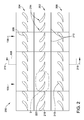
- FIG. 2 is a diagram of an exemplary section 200 of gas turbine assembly 100
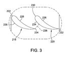
- Figure 3 is an enlarged section of the diagram shown in Figure 2 taken within area 3.
- section 200 includes a stator stage 202 (such as, for example, second stator stage 130) spaced axially between an upstream rotor stage 204 (such as, for example, first rotor stage 122) and a downstream rotor stage 206 (such as, for example, second rotor stage 124).
- stator stage 202 such as, for example, second stator stage 130
- an upstream rotor stage 204 such as, for example, first rotor stage 122
- a downstream rotor stage 206 such as, for example, second rotor stage 124
- Upstream rotor stage 204 has an annular arrangement of circumferentially-spaced, airfoil-shaped rotor blades 208
- downstream rotor stage 206 has an annular arrangement of circumferentially-spaced, airfoil-shaped rotor blades 210.
- upstream rotor stage 204 and downstream rotor stage 206 of section 200 are coupled to, and are rotatable with, rotor shaft 108 about centerline axis 112 of gas turbine assembly 100.
- Stator stage 202 includes a plurality of stator vane segments 212 that are coupled together in an annular formation.
- each segment 212 includes a pair of stator vanes 214 (commonly referred to as a "doublet").
- each segment 212 may instead have only one stator vane 214 (commonly referred to as a "singlet”), may have three stator vanes 214 (commonly referred to as a "triplet"), or may have four stator vanes 214 (commonly referred to as a "quadruplet").
- stator stage 202 may have any suitable number segments 212, and/or stator vanes 214 per segment 212, that enables section 200 to function as described herein.
- combustion gases 138 discharged from combustor 104 are channeled through upstream rotor stage 204, stator stage 202, and into downstream rotor stage 206.
- combustion gases 138 drive rotor stages 204 and 206 in a rotational direction 216 relative to stator stage 202 such that each rotor blade 210 of downstream rotor stage 206 may experience a vibratory stimulus as it passes each corresponding stator vane 214 (or segment 212).
- stator stage 202 is provided with forty-eight stator vanes 214
- each rotor blade 210 of downstream rotor stage 206 may experience forty-eight vibratory stimulus events per revolution.
- the frequency of vibratory stimulus may be related to the quantity of segments 212 (e.g., the stator stage 202 may have twenty-four segments 212, each being a doublet, which may yield twenty-four stimulus events per revolution).
- the frequency of the vibratory stimulus events may coincide with the resonant frequency of rotor blades 210, which may in turn render rotor blades 210 more susceptible to failure (e.g., fracture and/or deformation) if the magnitude of the vibratory stimulus exceeds a predetermined threshold.
- stator vanes 214 of each segment 212 are airfoil-shaped and are fixed side-by-side in the manner of a first stator vane 218 and a second stator vane 220.
- Each first stator vane 218 has a first leading edge 222, a first trailing edge 224, a first suction side 226, and a first pressure side 228.
- each second stator vane 220 has a second leading edge 230, a second trailing edge 232, a second suction side 234, and a second pressure side 236.
- throats 238 of stator stage 202 define the mass flow of combustion gases 138 through stator stage 202, and hence the size of each throat 238 is a parameter that can significantly affect the overall operating efficiency of gas turbine assembly 100.
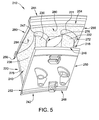
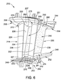
- Figures 4-7 are each perspective views of an exemplary segment 212 with a thermal barrier coating 240 applied thereto.
- each segment 212 e.g., first stator vane 218 and second stator vane 220
- thermal barrier coating 240 is applied to one or more segments 212 (e.g., to one or both vanes 218 and 220 of each segment 212) in an effort to reduce the likelihood that segments 212 will experience low cycle fatigue and creep-related cracking at higher temperatures.
- thermal barrier coating 240 may also be applied to rotor blades 208 and/or 210 in other embodiments.
- thermal barrier coating 240 may be thick enough to undesirably alter the geometry of segment(s) 212 in a manner that reduces the mass flow of combustion gases 138 through stator stage 202 by, for example, decreasing the cross-sectional flow area of throats 238. This could, in turn, increase the vibratory stimulus imparted to rotor blades 210 to a magnitude that is above a predetermined threshold, which could make rotor blades 210 more susceptible to failure. It is therefore desirable to apply thermal barrier coating 240 to segment(s) 212 in a manner that facilitates segment(s) 212 withstanding higher temperatures, while also minimizing associated increases in the magnitude of the vibratory stimulus imparted to rotor blades 210.
- first and second stator vanes 218 and 220 each extend between a radially inner sidewall 242 and a radially outer sidewall 244.
- Inner sidewall 242 has a forward edge 246, an aft edge 248, a first side edge 250 adjacent to first stator vane 218, and a second side edge 252 adjacent to second stator vane 220.
- outer sidewall 244 has a forward edge 254, an aft edge 256, a first side edge 258 adjacent to first stator vane 218, and a second side edge 260 adjacent to second stator vane 220.
- inner sidewall 242 and/or outer sidewall 244 may have any suitable configurations that enable segment 212 functioning as described herein.
- First stator vane 218 has a first inner fillet 270 and a first outer fillet 272 at which first stator vane 218 is coupled to inner sidewall 242 and outer sidewall 244, respectively.
- second stator vane 220 has a second inner fillet 274 and a second outer fillet 276 at which second stator vane 220 is coupled to inner sidewall 242 and outer sidewall 244, respectively.
- first leading edge 222, first trailing edge 224, first suction side 226, and first pressure side 228 each have an inner fillet region 223, 225, 227 and 229, respectively, and an outer fillet region 231, 233, 235 and 237, respectively.
- stator vanes 218 and 220 may be coupled to sidewalls 242 and 244 in any suitable manner that enables vanes 218 and 220 to function as described herein.
- thermal barrier coating 240 is an integrally-formed, single-piece structure that is not applied uniformly across the entire segment 212 (e.g., thermal barrier coating 240 may be applied to at least one surface of second stator vane 220, but not to the analogous surface(s) of first stator vane 218, and/or thermal barrier coating 240 may be applied to at least one surface of outer sidewall 244, but not to the analogous surface(s) of inner sidewall 242). Rather, in the exemplary embodiment, thermal barrier coating 240 is selectively applied to only those surfaces of segment 212 at which stresses are likely to concentrate when segment 212 is exposed to higher-temperature operating conditions.
- thermal barrier coating 240 is applied only to first leading edge 222, such that first leading edge 222 is entirely covered except for its inner fillet region 223.
- thermal barrier coating 240 is not applied to first trailing edge 224, first suction side 226, and/or first pressure side 228.
- thermal barrier coating 240 may be applied to first stator vane 218 in any suitable manner that enables segment 212 to function as described herein.
- thermal barrier coating 240 is applied only to second leading edge 230 and second pressure side 236, such that second leading edge 230 and second pressure side 236 are entirely covered except for: (A) their inner fillet regions 239 and 245, respectively; and (B) a margin 278 defined on second pressure side 236 at second trailing edge 232 that extends from inner fillet region 245 of second pressure side 236 towards outer fillet region 253 of second pressure side 236. More specifically, in the exemplary embodiment, margin 278 extends from about four-fifths to about nine-tenths of the way to outer fillet region 253 of second pressure side 236 from inner fillet region 245 of second pressure side 236.
- thermal barrier coating 240 is not applied to second suction side 234 and second trailing edge 232.
- thermal barrier coating 240 may be applied to second stator vane 220 in any suitable manner that enables segment 212 to function as described herein.
- thermal barrier coating 240 is applied only to: (A) a forward region 280 of its radially inner surface 282 (e.g., thermal barrier coating 240 may be confined to the forwardmost one-fifth, one-fourth, or one-third of radially inner surface 282); and (B) a first side region 284 of its radially inner surface between 282 (e.g., thermal barrier coating 240 may completely cover radially inner surface 282 from second pressure side 236 to second side edge 260).
- thermal barrier coating 240 is not applied to the radially outer surface 286 of inner sidewall 242.
- thermal barrier coating 240 may be applied to inner sidewall 242 and/or outer sidewall 244 in any suitable manner that enables segment 212 to function as described herein (e.g., thermal barrier coating 240 may be applied to radially outer surface 286 of inner sidewall 242 but not to radially inner surface 282 of outer sidewall 244 in one embodiment, or thermal barrier coating 240 may be applied to both radially outer surface 286 of inner sidewall 242 and radially inner surface 282 of outer sidewall 244 in another embodiment).
- stator stage 202 is more apt to withstand temperatures above the upper limit of its ideal range of operating temperatures. Moreover, the size of throats 238 remains substantially unchanged as compared to segments 212 to which no thermal barrier coating 240 has been applied, because pressure sides 228 and 236 are substantially uncoated at their corresponding trailing edges 224 and 232 (except near outer fillet region 253 of second pressure side 236 at second trailing edge 232). As such, undesirably high vibratory stimuli imparted on rotor blades 210 of downstream rotor stage 206 are facilitated to be minimized.
- the methods and systems described herein can facilitate enabling increases to engine firing temperatures of a turbine assembly by selectively coating turbine stator components, such as, but not limited to, the second stage turbine nozzle, with a thermal barrier coating in a manner that facilitates reducing their operating temperatures and increasing their useful life.
- the methods and systems can also provide for leaving turbine stator components substantially uncoated in areas that define a nozzle throat.
- the methods and systems may facilitate reducing harmonic stimulus to, and potential harmonic resonance of, downstream turbine rotor components.
- the methods and systems may thereby facilitate reducing the likelihood of high cycle fatigue failure of the downstream turbine rotor components.
- the methods and systems further can facilitate not altering or otherwise adversely affecting the durability and/or overall operating efficiency of an already-fabricated and/or already-operational gas turbine assembly when applying a thermal barrier coating to its turbine components. More specifically, the methods and systems may facilitate retrofitting existing turbine componentry with a thermal barrier coating without adversely altering the durability and/or overall operating efficiency of the gas turbine assembly.
Landscapes
- Engineering & Computer Science (AREA)
- Mechanical Engineering (AREA)
- General Engineering & Computer Science (AREA)
- Chemical & Material Sciences (AREA)
- Materials Engineering (AREA)
- Physics & Mathematics (AREA)
- Fluid Mechanics (AREA)
- Turbine Rotor Nozzle Sealing (AREA)
- Structures Of Non-Positive Displacement Pumps (AREA)
Abstract
Description
- The field of this disclosure relates generally to gas turbine components and, more particularly, to a thermal barrier coating for use with a gas turbine component.
- At least some known gas turbine assemblies include a compressor, a combustor, and a turbine. Gases flow into the compressor and are compressed. The compressed gases are then discharged into the combustor, mixed with fuel, and ignited to generate combustion gases. The combustion gases are channeled from the combustor through the turbine, thereby driving the turbine which, in turn, may power an electrical generator coupled to the turbine.
- Known gas turbine components (e.g., turbine stator components) may be susceptible to deformation and/or fracture during higher-temperature operating cycles. To reduce the effects of exposure to higher temperatures, it is known to apply a thermal barrier coating to at least some known gas turbine components, thereby improving the useful life of the components. However, the thermal barrier coating can alter the geometry of the components, which can adversely affect the overall operating efficiency of the gas turbine assembly. As such, the usefulness of such coatings may be limited.
- In one aspect of the present invention, a gas turbine component is provided. The gas turbine component includes an airfoil having a leading edge, a trailing edge, a suction side extending from the leading edge to the trailing edge, and a pressure side extending from the leading edge to the trailing edge opposite the suction side. The gas turbine component also includes a thermal barrier coating applied to the airfoil pressure side such that an uncoated margin is defined on the pressure side at the trailing edge.
- In another aspect, a method of assembling a gas turbine component is provided. The method includes providing an airfoil having a leading edge, a trailing edge, a suction side extending from the leading edge to the trailing edge, and a pressure side extending from the leading edge to the trailing edge opposite the suction side. The method also includes applying a thermal barrier coating to the airfoil such that the thermal barrier coating is on the pressure side of the airfoil and such that an uncoated margin is defined on the pressure side at the trailing edge.
- In another aspect, a gas turbine component is provided. The gas turbine component includes a first airfoil having a first leading edge, a first trailing edge, a first suction side extending from the first leading edge to the first trailing edge, and a first pressure side extending from the first leading edge to the first trailing edge opposite the first suction side. The gas turbine component also includes a second airfoil having a second leading edge, a second trailing edge, a second suction side extending from the second leading edge to the second trailing edge, and a second pressure side extending from the second leading edge to the second trailing edge opposite the second suction side. The gas turbine component further includes a thermal barrier coating applied to the second pressure side of the second airfoil. The thermal barrier coating is not applied to the first pressure side of the first airfoil.
- In the drawings:
-
Figure 1 is a schematic view of an exemplary gas turbine assembly; -
Figure 2 is a diagram of an exemplary section of the gas turbine assembly shown inFigure 1 ; -
Figure 3 is an enlarged portion of the diagram shown inFigure 2 taken withinarea 3; -
Figure 4 is a perspective view of an exemplary stator vane segment of the section shown inFigure 2 ; -
Figure 5 is another perspective view of the stator vane segment shown inFigure 4 ; -
Figure 6 is yet another perspective view of the stator vane segment shown inFigure 4 ; and -
Figure 7 is a further perspective view of the stator vane segment shown inFigure 4 . - The following detailed description illustrates gas turbine components and methods of assembling the same by way of example and not by way of limitation. The description should enable one of ordinary skill in the art to make and use the components, and the description describes several embodiments of the components, including what is presently believed to be the best modes of making and using the components. An exemplary component is described herein as being coupled within a gas turbine assembly. However, it is contemplated that the component has general application to a broad range of systems in a variety of fields other than gas turbine assemblies.
-
Figure 1 illustrates an exemplarygas turbine assembly 100. In the exemplary embodiment,gas turbine assembly 100 has acompressor 102, acombustor 104, and aturbine 106 coupled in flow communication with one another within acasing 110 and spaced along acenterline axis 112.Compressor 102 includes a plurality ofrotor blades 114 and a plurality ofstator vanes 116, andturbine 106 likewise includes a plurality ofrotor blades 118 and a plurality ofstator vanes 120. Notably, turbine rotor blades 118 (or buckets) are grouped in a plurality of annular, axially-spaced stages (e.g., afirst rotor stage 122, asecond rotor stage 124, and a third rotor stage 126) that are rotatable in unison via an axially-alignedrotor shaft 108. Similarly, stator vanes 120 (or nozzles) are grouped in a plurality of annular, axially-spaced stages (e.g., afirst stator stage 128, asecond stator stage 130, and a third stator stage 132) that are axially-interspaced withrotor stages first rotor stage 122 is spaced axially between first andsecond stator stages second rotor stage 124 is spaced axially between second andthird stator stages third rotor stage 126 is spaced downstream fromthird stator stage 132. - In operation, working gases 134 (e.g., ambient air) flow into
compressor 102 and are compressed and channeled intocombustor 104. Compressedgases 136 are mixed with fuel and ignited incombustor 104 to generatecombustion gases 138 that are channeled intoturbine 106. In an axially-sequential manner,combustion gases 138 flow throughfirst stator stage 128,first rotor stage 122,second stator stage 130,second rotor stage 124,third stator stage 132, andthird rotor stage 126 interacting withrotor blades 118 to driverotor shaft 108 which may, in turn, drive an electrical generator (not shown) coupled torotor shaft 108.Combustion gases 138 are then discharged fromturbine 106 asexhaust gases 140. -
Figures 2 is a diagram of anexemplary section 200 ofgas turbine assembly 100, andFigure 3 is an enlarged section of the diagram shown inFigure 2 taken withinarea 3. In the exemplary embodiment,section 200 includes a stator stage 202 (such as, for example, second stator stage 130) spaced axially between an upstream rotor stage 204 (such as, for example, first rotor stage 122) and a downstream rotor stage 206 (such as, for example, second rotor stage 124).Upstream rotor stage 204 has an annular arrangement of circumferentially-spaced, airfoil-shaped rotor blades 208, anddownstream rotor stage 206 has an annular arrangement of circumferentially-spaced, airfoil-shaped rotor blades 210. Notably,upstream rotor stage 204 anddownstream rotor stage 206 ofsection 200 are coupled to, and are rotatable with,rotor shaft 108 aboutcenterline axis 112 ofgas turbine assembly 100. -
Stator stage 202 includes a plurality ofstator vane segments 212 that are coupled together in an annular formation. In the exemplary embodiment, eachsegment 212 includes a pair of stator vanes 214 (commonly referred to as a "doublet"). In other embodiments, eachsegment 212 may instead have only one stator vane 214 (commonly referred to as a "singlet"), may have three stator vanes 214 (commonly referred to as a "triplet"), or may have four stator vanes 214 (commonly referred to as a "quadruplet"). Alternatively,stator stage 202 may have anysuitable number segments 212, and/orstator vanes 214 persegment 212, that enablessection 200 to function as described herein. - During operation of
gas turbine assembly 100 withsection 200 used inturbine 106,combustion gases 138 discharged fromcombustor 104 are channeled throughupstream rotor stage 204,stator stage 202, and intodownstream rotor stage 206. As such,combustion gases 138drive rotor stages rotational direction 216 relative tostator stage 202 such that eachrotor blade 210 ofdownstream rotor stage 206 may experience a vibratory stimulus as it passes each corresponding stator vane 214 (or segment 212). For example, ifstator stage 202 is provided with forty-eightstator vanes 214, eachrotor blade 210 ofdownstream rotor stage 206 may experience forty-eight vibratory stimulus events per revolution. Alternatively, the frequency of vibratory stimulus may be related to the quantity of segments 212 (e.g., thestator stage 202 may have twenty-foursegments 212, each being a doublet, which may yield twenty-four stimulus events per revolution). In some operating cycles ofgas turbine assembly 100, the frequency of the vibratory stimulus events may coincide with the resonant frequency ofrotor blades 210, which may in turnrender rotor blades 210 more susceptible to failure (e.g., fracture and/or deformation) if the magnitude of the vibratory stimulus exceeds a predetermined threshold. Hence, it is desirable to reduce the magnitude of each vibratory stimulus imparted to eachrotor blade 210. - In the exemplary embodiment,
stator vanes 214 of eachsegment 212 are airfoil-shaped and are fixed side-by-side in the manner of afirst stator vane 218 and asecond stator vane 220. Eachfirst stator vane 218 has a first leadingedge 222, a firsttrailing edge 224, afirst suction side 226, and afirst pressure side 228. Similarly, eachsecond stator vane 220 has a second leadingedge 230, a secondtrailing edge 232, asecond suction side 234, and asecond pressure side 236. Notably, the minimum area betweenadjacent stator vanes 218 and 220 (e.g., as measured at the associatedtrailing edge 224 or 232) is a parameter commonly referred to as a "throat" 238 of thatturbine stage 202. Collectively,throats 238 ofstator stage 202 define the mass flow ofcombustion gases 138 throughstator stage 202, and hence the size of eachthroat 238 is a parameter that can significantly affect the overall operating efficiency ofgas turbine assembly 100. -
Figures 4-7 are each perspective views of anexemplary segment 212 with athermal barrier coating 240 applied thereto. In the exemplary embodiment, each segment 212 (e.g.,first stator vane 218 and second stator vane 220) is fabricated from a suitable metal or alloy of metals, so as to have an ideal range of operating temperatures within which structural integrity is facilitated to be maintained. However, it may be desirable in some instances to operategas turbine assembly 100 in a manner that may exposesegments 212 to temperatures above the upper limit of their ideal range of operating temperatures. Because long term exposure to such elevated temperatures can have an undesirable effect on the structural integrity of segments 212 (e.g., becausesegments 212 can experience low cycle fatigue and creep-related cracking at such temperatures), in the exemplary embodiment,thermal barrier coating 240 is applied to one or more segments 212 (e.g., to one or bothvanes segments 212 will experience low cycle fatigue and creep-related cracking at higher temperatures. Optionally, in the manner set forth herein,thermal barrier coating 240 may also be applied torotor blades 208 and/or 210 in other embodiments. - In some instances, however,
thermal barrier coating 240 may be thick enough to undesirably alter the geometry of segment(s) 212 in a manner that reduces the mass flow ofcombustion gases 138 throughstator stage 202 by, for example, decreasing the cross-sectional flow area ofthroats 238. This could, in turn, increase the vibratory stimulus imparted torotor blades 210 to a magnitude that is above a predetermined threshold, which could makerotor blades 210 more susceptible to failure. It is therefore desirable to applythermal barrier coating 240 to segment(s) 212 in a manner that facilitates segment(s) 212 withstanding higher temperatures, while also minimizing associated increases in the magnitude of the vibratory stimulus imparted torotor blades 210. - In the exemplary embodiment, first and
second stator vanes inner sidewall 242 and a radiallyouter sidewall 244.Inner sidewall 242 has aforward edge 246, anaft edge 248, afirst side edge 250 adjacent tofirst stator vane 218, and asecond side edge 252 adjacent tosecond stator vane 220. Similarly,outer sidewall 244 has aforward edge 254, anaft edge 256, afirst side edge 258 adjacent tofirst stator vane 218, and asecond side edge 260 adjacent tosecond stator vane 220. In other embodiments,inner sidewall 242 and/orouter sidewall 244 may have any suitable configurations that enablesegment 212 functioning as described herein. -
First stator vane 218 has a firstinner fillet 270 and a firstouter fillet 272 at whichfirst stator vane 218 is coupled toinner sidewall 242 andouter sidewall 244, respectively. Similarly,second stator vane 220 has a secondinner fillet 274 and a secondouter fillet 276 at whichsecond stator vane 220 is coupled toinner sidewall 242 andouter sidewall 244, respectively. As such, in the exemplary embodiment, firstleading edge 222, first trailingedge 224,first suction side 226, andfirst pressure side 228 each have aninner fillet region outer fillet region leading edge 230,second trailing edge 232,second suction side 234, andsecond pressure side 236 each have aninner fillet region outer fillet region stator vanes sidewalls vanes - Notably, in the exemplary embodiment,
thermal barrier coating 240 is an integrally-formed, single-piece structure that is not applied uniformly across the entire segment 212 (e.g.,thermal barrier coating 240 may be applied to at least one surface ofsecond stator vane 220, but not to the analogous surface(s) offirst stator vane 218, and/orthermal barrier coating 240 may be applied to at least one surface ofouter sidewall 244, but not to the analogous surface(s) of inner sidewall 242). Rather, in the exemplary embodiment,thermal barrier coating 240 is selectively applied to only those surfaces ofsegment 212 at which stresses are likely to concentrate whensegment 212 is exposed to higher-temperature operating conditions. For example, in the exemplary embodiment, with respect tofirst stator vane 218,thermal barrier coating 240 is applied only to firstleading edge 222, such that firstleading edge 222 is entirely covered except for itsinner fillet region 223. Notably, in such an embodiment,thermal barrier coating 240 is not applied tofirst trailing edge 224,first suction side 226, and/orfirst pressure side 228. In other embodiments,thermal barrier coating 240 may be applied tofirst stator vane 218 in any suitable manner that enablessegment 212 to function as described herein. - With respect to
second stator vane 220,thermal barrier coating 240 is applied only to secondleading edge 230 andsecond pressure side 236, such that secondleading edge 230 andsecond pressure side 236 are entirely covered except for: (A) theirinner fillet regions margin 278 defined onsecond pressure side 236 atsecond trailing edge 232 that extends frominner fillet region 245 ofsecond pressure side 236 towardsouter fillet region 253 ofsecond pressure side 236. More specifically, in the exemplary embodiment,margin 278 extends from about four-fifths to about nine-tenths of the way toouter fillet region 253 ofsecond pressure side 236 frominner fillet region 245 ofsecond pressure side 236. Notably,thermal barrier coating 240 is not applied tosecond suction side 234 andsecond trailing edge 232. In other embodiments,thermal barrier coating 240 may be applied tosecond stator vane 220 in any suitable manner that enablessegment 212 to function as described herein. - With respect to
outer sidewall 244,thermal barrier coating 240 is applied only to: (A) aforward region 280 of its radially inner surface 282 (e.g.,thermal barrier coating 240 may be confined to the forwardmost one-fifth, one-fourth, or one-third of radially inner surface 282); and (B) afirst side region 284 of its radially inner surface between 282 (e.g.,thermal barrier coating 240 may completely cover radiallyinner surface 282 fromsecond pressure side 236 to second side edge 260). Notably,thermal barrier coating 240 is not applied to the radiallyouter surface 286 ofinner sidewall 242. In other embodiments,thermal barrier coating 240 may be applied toinner sidewall 242 and/orouter sidewall 244 in any suitable manner that enablessegment 212 to function as described herein (e.g.,thermal barrier coating 240 may be applied to radiallyouter surface 286 ofinner sidewall 242 but not to radiallyinner surface 282 ofouter sidewall 244 in one embodiment, orthermal barrier coating 240 may be applied to both radiallyouter surface 286 ofinner sidewall 242 and radiallyinner surface 282 ofouter sidewall 244 in another embodiment). - During operation of
gas turbine assembly 100, when all, or at least some, ofsegments 212 ofstator stage 202 are coated withthermal barrier coating 240 as described herein,stator stage 202 is more apt to withstand temperatures above the upper limit of its ideal range of operating temperatures. Moreover, the size ofthroats 238 remains substantially unchanged as compared tosegments 212 to which nothermal barrier coating 240 has been applied, because pressure sides 228 and 236 are substantially uncoated at theircorresponding trailing edges 224 and 232 (except nearouter fillet region 253 ofsecond pressure side 236 at second trailing edge 232). As such, undesirably high vibratory stimuli imparted onrotor blades 210 ofdownstream rotor stage 206 are facilitated to be minimized. - The methods and systems described herein can facilitate enabling increases to engine firing temperatures of a turbine assembly by selectively coating turbine stator components, such as, but not limited to, the second stage turbine nozzle, with a thermal barrier coating in a manner that facilitates reducing their operating temperatures and increasing their useful life. The methods and systems can also provide for leaving turbine stator components substantially uncoated in areas that define a nozzle throat. Thus, the methods and systems may facilitate reducing harmonic stimulus to, and potential harmonic resonance of, downstream turbine rotor components. The methods and systems may thereby facilitate reducing the likelihood of high cycle fatigue failure of the downstream turbine rotor components. The methods and systems further can facilitate not altering or otherwise adversely affecting the durability and/or overall operating efficiency of an already-fabricated and/or already-operational gas turbine assembly when applying a thermal barrier coating to its turbine components. More specifically, the methods and systems may facilitate retrofitting existing turbine componentry with a thermal barrier coating without adversely altering the durability and/or overall operating efficiency of the gas turbine assembly.
- Exemplary embodiments of gas turbine components and methods of assembling the same are described above in detail. The methods and systems described herein are not limited to the specific embodiments described herein, but rather, components of the methods and systems may be utilized independently and separately from other components described herein. For example, the methods and systems described herein may have other applications not limited to practice with gas turbine assemblies, as described herein. Rather, the methods and systems described herein can be implemented and utilized in connection with various other industries.
- While the invention has been described in terms of various specific embodiments, those skilled in the art will recognize that the invention can be practiced with modification within the spirit and scope of the claims.
- Various aspects and embodiments of the present invention are defined by the following numbered clauses:
- 1. A gas turbine component comprising:
- an airfoil comprising a leading edge, a trailing edge, a suction side extending from said leading edge to said trailing edge, and a pressure side extending from said leading edge to said trailing edge opposite said suction side; and
- a thermal barrier coating applied to said airfoil pressure side such that an uncoated margin is defined on said pressure side at said trailing edge.
- 2. A gas turbine component in accordance with any preceding clause, herein said thermal barrier coating is applied across said airfoil leading edge.
- 3. A gas turbine component in accordance with any preceding clause, wherein said thermal barrier coating is not applied to said airfoil suction side.
- 4. A gas turbine component in accordance with any preceding clause, wherein said component comprises an inner sidewall and an outer sidewall such that said airfoil extends from said inner sidewall to said outer sidewall, said thermal barrier coating applied to at least one of said inner sidewall and said outer sidewall.
- 5. A gas turbine component in accordance with any preceding clause, wherein said thermal barrier coating is applied to said inner sidewall and is not applied to said outer sidewall.
- 6. A gas turbine component in accordance with any preceding clause, wherein said thermal barrier coating is applied to said outer sidewall and is not applied to said inner sidewall.
- 7. A method of assembling a gas turbine component, said method comprising:
- providing an airfoil having a leading edge, a trailing edge, a suction side extending from the leading edge to the trailing edge, and a pressure side extending from the leading edge to the trailing edge opposite the suction side; and
- applying a thermal barrier coating to the airfoil such that the thermal barrier coating is on the pressure side of the airfoil and such that an uncoated margin is defined on the pressure side at the trailing edge.
- 8. A method in accordance with any preceding clause, further comprising applying the thermal barrier coating to the airfoil such that the thermal barrier coating extends across the airfoil leading edge.
- 9. A method in accordance with any preceding clause, further comprising applying the thermal barrier coating to the airfoil such that the thermal barrier coating is not on the airfoil suction side.
- 10. A method in accordance with any preceding clause, further comprising coupling the airfoil between an inner sidewall and an outer sidewall.
- 11. A method in accordance with any preceding clause, further comprising applying the thermal barrier coating to the outer sidewall.
- 12. A gas turbine component comprising:
- a first airfoil comprising a first leading edge, a first trailing edge, a first suction side extending from said first leading edge to said first trailing edge, and a first pressure side extending from said first leading edge to said first trailing edge opposite said first suction side;
- a second airfoil comprising a second leading edge, a second trailing edge, a second suction side extending from said second leading edge to said second trailing edge, and a second pressure side extending from said second leading edge to said second trailing edge opposite said second suction side; and
- a thermal barrier coating applied to said second pressure side of said second airfoil, wherein said thermal barrier coating is not applied to said first pressure side of said first airfoil.
- 13. A gas turbine component in accordance with any preceding clause, wherein said thermal barrier coating is applied to said second pressure side such that an uncoated margin is defined on said second pressure side at said second trailing edge.
- 14. A gas turbine component in accordance with any preceding clause, wherein said thermal barrier coating is applied across said first leading edge of said first airfoil and said second leading edge of said second airfoil.
- 15. A gas turbine component in accordance with any preceding clause, wherein said thermal barrier coating is not applied to said first suction side of said first airfoil or said second suction side of said second airfoil.
- 16. A gas turbine component in accordance with any preceding clause, further comprising an inner sidewall and an outer sidewall, wherein said airfoils are coupled between said sidewalls.
- 17. A gas turbine component in accordance with any preceding clause, wherein said thermal barrier coating is applied to said outer sidewall.
- 18. A gas turbine component in accordance with any preceding clause, wherein said outer sidewall comprises a side edge adjacent said second airfoil, said thermal barrier coating applied between said second pressure side and said side edge.
- 19. A gas turbine component in accordance with any preceding clause, wherein said thermal barrier coating is not applied to said inner sidewall.
- 20. A gas turbine component in accordance with any preceding clause, wherein said airfoils are stator vanes.
Claims (10)
- A gas turbine component comprising:an airfoil comprising a leading edge (222, 230), a trailing edge (224, 232), a suction side (226, 234) extending from said leading edge to said trailing edge, and a pressure side (228, 236) extending from said leading edge to said trailing edge opposite said suction side; anda thermal barrier coating (240) applied to said airfoil pressure side such that an uncoated margin (278) is defined on said pressure side at said trailing edge.
- A gas turbine component in accordance with Claim 1, wherein said thermal barrier coating (240) is applied across said airfoil leading edge (222, 230).
- A gas turbine component in accordance with any preceding Claim, wherein said thermal barrier coating (240) is not applied to said airfoil suction side (226, 234).
- A gas turbine component in accordance with any preceding Claim, wherein said component comprises an inner sidewall (242) and an outer sidewall (244) such that said airfoil extends from said inner sidewall to said outer sidewall, said thermal barrier coating (240) applied to at least one of said inner sidewall and said outer sidewall.
- A gas turbine component in accordance with any preceding Claim, wherein said thermal barrier coating (240) is applied to said inner sidewall (242) and is not applied to said outer sidewall (244).
- A gas turbine component in accordance with any of Claims 1 to 4, wherein said thermal barrier coating (240) is applied to said outer sidewall (244) and is not applied to said inner sidewall (242).
- A gas turbine component comprising:a first airfoil comprising a first leading edge (222), a first trailing edge (224), a first suction side (226) extending from said first leading edge to said first trailing edge, and a first pressure side (228) extending from said first leading edge to said first trailing edge opposite said first suction side;a second airfoil comprising a second leading edge (230), a second trailing edge (232), a second suction side (234) extending from said second leading edge to said second trailing edge, and a second pressure side (236) extending from said second leading edge to said second trailing edge opposite said second suction side; anda thermal barrier coating (240) applied to said second pressure side of said second airfoil, wherein said thermal barrier coating is not applied to said first pressure side of said first airfoil.
- A gas turbine component in accordance with Claim 7, wherein said thermal barrier coating (240) is applied to said second pressure side (236) such that an uncoated margin (278) is defined on said second pressure side at said second trailing edge (232).
- A gas turbine component in accordance with Claim 7 or Claim 8, wherein said thermal barrier coating (240) is applied across said first leading edge (222) of said first airfoil and said second leading edge (230) of said second airfoil.
- A gas turbine component in accordance with any of Claims 7 to 9, wherein said thermal barrier coating (240) is not applied to said first suction side (226) of said first airfoil or said second suction side (234) of said second airfoil.
Applications Claiming Priority (1)
| Application Number | Priority Date | Filing Date | Title |
|---|---|---|---|
| US14/841,056 US10047613B2 (en) | 2015-08-31 | 2015-08-31 | Gas turbine components having non-uniformly applied coating and methods of assembling the same |
Publications (2)
| Publication Number | Publication Date |
|---|---|
| EP3135865A1 true EP3135865A1 (en) | 2017-03-01 |
| EP3135865B1 EP3135865B1 (en) | 2022-11-16 |
Family
ID=56682034
Family Applications (1)
| Application Number | Title | Priority Date | Filing Date |
|---|---|---|---|
| EP16183749.7A Active EP3135865B1 (en) | 2015-08-31 | 2016-08-11 | Gas turbine component |
Country Status (4)
| Country | Link |
|---|---|
| US (1) | US10047613B2 (en) |
| EP (1) | EP3135865B1 (en) |
| JP (1) | JP6835501B2 (en) |
| CN (1) | CN106481365B (en) |
Families Citing this family (5)
| Publication number | Priority date | Publication date | Assignee | Title |
|---|---|---|---|---|
| US10641720B2 (en) | 2017-10-06 | 2020-05-05 | General Electric Company | Thermal barrier coating spallation detection system |
| EP3530882A1 (en) * | 2018-02-26 | 2019-08-28 | MTU Aero Engines GmbH | Method of manufacturing a guide vane segment for a gas turbine and vane segment having a goating |
| CN116710632A (en) * | 2020-08-24 | 2023-09-05 | 西门子能源全球有限两合公司 | gas turbine blade |
| US11773732B2 (en) * | 2021-04-21 | 2023-10-03 | General Electric Company | Rotor blade with protective layer |
| US12152502B2 (en) * | 2021-10-29 | 2024-11-26 | Pratt & Whitney Canada Corp. | Selectively coated gas path surfaces within a hot section of a gas turbine engine |
Citations (5)
| Publication number | Priority date | Publication date | Assignee | Title |
|---|---|---|---|---|
| EP1013883A2 (en) * | 1998-12-21 | 2000-06-28 | General Electric Company | Aerodynamic shaped article and method for making the same |
| US20070148003A1 (en) * | 2004-05-10 | 2007-06-28 | Alexander Trishkin | Fluid flow machine blade |
| EP2325441A2 (en) * | 2009-11-13 | 2011-05-25 | United Technologies Corporation | Gas turbine engine component with discontinuous coated areas and corresponding coating method |
| US8070454B1 (en) * | 2007-12-12 | 2011-12-06 | Florida Turbine Technologies, Inc. | Turbine airfoil with trailing edge |
| WO2014095758A1 (en) * | 2012-12-20 | 2014-06-26 | Siemens Aktiengesellschaft | Vane segment for a gas turbine coated with a mcraly coating and tbc patches |
Family Cites Families (23)
| Publication number | Priority date | Publication date | Assignee | Title |
|---|---|---|---|---|
| US5209645A (en) * | 1988-05-06 | 1993-05-11 | Hitachi, Ltd. | Ceramics-coated heat resisting alloy member |
| US5645399A (en) | 1995-03-15 | 1997-07-08 | United Technologies Corporation | Gas turbine engine case coated with thermal barrier coating to control axial airfoil clearance |
| US6095755A (en) * | 1996-11-26 | 2000-08-01 | United Technologies Corporation | Gas turbine engine airfoils having increased fatigue strength |
| US6106231A (en) * | 1998-11-06 | 2000-08-22 | General Electric Company | Partially coated airfoil and method for making |
| US6126400A (en) * | 1999-02-01 | 2000-10-03 | General Electric Company | Thermal barrier coating wrap for turbine airfoil |
| US6254756B1 (en) * | 1999-08-11 | 2001-07-03 | General Electric Company | Preparation of components having a partial platinum coating thereon |
| US6403165B1 (en) | 2000-02-09 | 2002-06-11 | General Electric Company | Method for modifying stoichiometric NiAl coatings applied to turbine airfoils by thermal processes |
| US7008186B2 (en) | 2003-09-17 | 2006-03-07 | General Electric Company | Teardrop film cooled blade |
| US7008178B2 (en) * | 2003-12-17 | 2006-03-07 | General Electric Company | Inboard cooled nozzle doublet |
| US7186070B2 (en) | 2004-10-12 | 2007-03-06 | Honeywell International, Inc. | Method for modifying gas turbine nozzle area |
| US7422417B2 (en) | 2005-05-05 | 2008-09-09 | Florida Turbine Technologies, Inc. | Airfoil with a porous fiber metal layer |
| US7922455B2 (en) | 2005-09-19 | 2011-04-12 | General Electric Company | Steam-cooled gas turbine bucker for reduced tip leakage loss |
| US20080085191A1 (en) | 2006-10-05 | 2008-04-10 | Siemens Power Generation, Inc. | Thermal barrier coating system for a turbine airfoil usable in a turbine engine |
| US8197184B2 (en) * | 2006-10-18 | 2012-06-12 | United Technologies Corporation | Vane with enhanced heat transfer |
| US8708658B2 (en) * | 2007-04-12 | 2014-04-29 | United Technologies Corporation | Local application of a protective coating on a shrouded gas turbine engine component |
| US8157515B2 (en) * | 2008-08-01 | 2012-04-17 | General Electric Company | Split doublet power nozzle and related method |
| US8511993B2 (en) | 2009-08-14 | 2013-08-20 | Alstom Technology Ltd. | Application of dense vertically cracked and porous thermal barrier coating to a gas turbine component |
| US8317473B1 (en) | 2009-09-23 | 2012-11-27 | Florida Turbine Technologies, Inc. | Turbine blade with leading edge edge cooling |
| EP2418357A1 (en) | 2010-08-05 | 2012-02-15 | Siemens Aktiengesellschaft | Turbine airfoil and method for thermal barrier coating |
| US9394796B2 (en) | 2013-07-12 | 2016-07-19 | General Electric Company | Turbine component and methods of assembling the same |
| US8827632B1 (en) | 2013-11-20 | 2014-09-09 | Ching-Pang Lee | Integrated TBC and cooling flow metering plate in turbine vane |
| US10174626B2 (en) * | 2014-10-15 | 2019-01-08 | Pratt & Whitney Canada Corp. | Partially coated blade |
| US10358939B2 (en) * | 2015-03-11 | 2019-07-23 | Rolls-Royce Corporation | Turbine vane with heat shield |
-
2015
- 2015-08-31 US US14/841,056 patent/US10047613B2/en active Active
-
2016
- 2016-08-11 EP EP16183749.7A patent/EP3135865B1/en active Active
- 2016-08-18 JP JP2016160273A patent/JP6835501B2/en active Active
- 2016-08-31 CN CN201610774307.6A patent/CN106481365B/en active Active
Patent Citations (5)
| Publication number | Priority date | Publication date | Assignee | Title |
|---|---|---|---|---|
| EP1013883A2 (en) * | 1998-12-21 | 2000-06-28 | General Electric Company | Aerodynamic shaped article and method for making the same |
| US20070148003A1 (en) * | 2004-05-10 | 2007-06-28 | Alexander Trishkin | Fluid flow machine blade |
| US8070454B1 (en) * | 2007-12-12 | 2011-12-06 | Florida Turbine Technologies, Inc. | Turbine airfoil with trailing edge |
| EP2325441A2 (en) * | 2009-11-13 | 2011-05-25 | United Technologies Corporation | Gas turbine engine component with discontinuous coated areas and corresponding coating method |
| WO2014095758A1 (en) * | 2012-12-20 | 2014-06-26 | Siemens Aktiengesellschaft | Vane segment for a gas turbine coated with a mcraly coating and tbc patches |
Also Published As
| Publication number | Publication date |
|---|---|
| CN106481365B (en) | 2021-05-28 |
| US10047613B2 (en) | 2018-08-14 |
| JP6835501B2 (en) | 2021-02-24 |
| EP3135865B1 (en) | 2022-11-16 |
| US20170058682A1 (en) | 2017-03-02 |
| CN106481365A (en) | 2017-03-08 |
| JP2017053616A (en) | 2017-03-16 |
Similar Documents
| Publication | Publication Date | Title |
|---|---|---|
| US8313291B2 (en) | Turbine inlet guide vane with scalloped platform and related method | |
| CN104806299B (en) | Turbine bucket leaf with double partial-span shields and bending dovetail | |
| CN110131209B (en) | turbine engine with blades | |
| EP3135865B1 (en) | Gas turbine component | |
| US8740571B2 (en) | Turbine bucket for use in gas turbine engines and methods for fabricating the same | |
| US10280841B2 (en) | Baffle insert for a gas turbine engine component and method of cooling | |
| US10422233B2 (en) | Baffle insert for a gas turbine engine component and component with baffle insert | |
| CN107044444B (en) | Turbine engine compressor blade | |
| EP2204534A1 (en) | Turbine airfoil clocking | |
| US8235652B2 (en) | Turbine nozzle segment | |
| US10337334B2 (en) | Gas turbine engine component with a baffle insert | |
| US10287989B2 (en) | Seal support of titanium aluminide for a turbomachine | |
| US7874794B2 (en) | Blade row for a rotary machine and method of fabricating same | |
| US10577947B2 (en) | Baffle insert for a gas turbine engine component | |
| US20060078422A1 (en) | Method for modifying gas turbine nozzle area | |
| EP3543465B1 (en) | Blade having a tip cooling cavity and method of making same | |
| CN108331617B (en) | Components for impingement cooling and rotating machinery including the same | |
| US10753215B2 (en) | Turbine vane comprising a blade with a tub including a curved pressure side in a blade apex region | |
| EP4144959A1 (en) | Fluid machine for an aircraft engine and aircraft engine | |
| US11808168B2 (en) | Turbine bucket with dual part span shrouds and aerodynamic features | |
| WO2017200549A1 (en) | Tip shroud with a fence feature for discouraging pitch-wise over-tip leakage flow | |
| JP2021008820A (en) | Aircraft gas turbin |
Legal Events
| Date | Code | Title | Description |
|---|---|---|---|
| PUAI | Public reference made under article 153(3) epc to a published international application that has entered the european phase |
Free format text: ORIGINAL CODE: 0009012 |
|
| STAA | Information on the status of an ep patent application or granted ep patent |
Free format text: STATUS: THE APPLICATION HAS BEEN PUBLISHED |
|
| AK | Designated contracting states |
Kind code of ref document: A1 Designated state(s): AL AT BE BG CH CY CZ DE DK EE ES FI FR GB GR HR HU IE IS IT LI LT LU LV MC MK MT NL NO PL PT RO RS SE SI SK SM TR |
|
| AX | Request for extension of the european patent |
Extension state: BA ME |
|
| STAA | Information on the status of an ep patent application or granted ep patent |
Free format text: STATUS: REQUEST FOR EXAMINATION WAS MADE |
|
| 17P | Request for examination filed |
Effective date: 20170901 |
|
| RBV | Designated contracting states (corrected) |
Designated state(s): AL AT BE BG CH CY CZ DE DK EE ES FI FR GB GR HR HU IE IS IT LI LT LU LV MC MK MT NL NO PL PT RO RS SE SI SK SM TR |
|
| STAA | Information on the status of an ep patent application or granted ep patent |
Free format text: STATUS: EXAMINATION IS IN PROGRESS |
|
| 17Q | First examination report despatched |
Effective date: 20201008 |
|
| GRAP | Despatch of communication of intention to grant a patent |
Free format text: ORIGINAL CODE: EPIDOSNIGR1 |
|
| STAA | Information on the status of an ep patent application or granted ep patent |
Free format text: STATUS: GRANT OF PATENT IS INTENDED |
|
| INTG | Intention to grant announced |
Effective date: 20220719 |
|
| GRAS | Grant fee paid |
Free format text: ORIGINAL CODE: EPIDOSNIGR3 |
|
| GRAA | (expected) grant |
Free format text: ORIGINAL CODE: 0009210 |
|
| STAA | Information on the status of an ep patent application or granted ep patent |
Free format text: STATUS: THE PATENT HAS BEEN GRANTED |
|
| AK | Designated contracting states |
Kind code of ref document: B1 Designated state(s): AL AT BE BG CH CY CZ DE DK EE ES FI FR GB GR HR HU IE IS IT LI LT LU LV MC MK MT NL NO PL PT RO RS SE SI SK SM TR |
|
| REG | Reference to a national code |
Ref country code: GB Ref legal event code: FG4D |
|
| REG | Reference to a national code |
Ref country code: CH Ref legal event code: EP |
|
| REG | Reference to a national code |
Ref country code: IE Ref legal event code: FG4D |
|
| REG | Reference to a national code |
Ref country code: DE Ref legal event code: R096 Ref document number: 602016076320 Country of ref document: DE |
|
| REG | Reference to a national code |
Ref country code: AT Ref legal event code: REF Ref document number: 1531884 Country of ref document: AT Kind code of ref document: T Effective date: 20221215 |
|
| REG | Reference to a national code |
Ref country code: LT Ref legal event code: MG9D |
|
| REG | Reference to a national code |
Ref country code: NL Ref legal event code: MP Effective date: 20221116 |
|
| REG | Reference to a national code |
Ref country code: AT Ref legal event code: MK05 Ref document number: 1531884 Country of ref document: AT Kind code of ref document: T Effective date: 20221116 |
|
| PG25 | Lapsed in a contracting state [announced via postgrant information from national office to epo] |
Ref country code: SE Free format text: LAPSE BECAUSE OF FAILURE TO SUBMIT A TRANSLATION OF THE DESCRIPTION OR TO PAY THE FEE WITHIN THE PRESCRIBED TIME-LIMIT Effective date: 20221116 Ref country code: PT Free format text: LAPSE BECAUSE OF FAILURE TO SUBMIT A TRANSLATION OF THE DESCRIPTION OR TO PAY THE FEE WITHIN THE PRESCRIBED TIME-LIMIT Effective date: 20230316 Ref country code: NO Free format text: LAPSE BECAUSE OF FAILURE TO SUBMIT A TRANSLATION OF THE DESCRIPTION OR TO PAY THE FEE WITHIN THE PRESCRIBED TIME-LIMIT Effective date: 20230216 Ref country code: LT Free format text: LAPSE BECAUSE OF FAILURE TO SUBMIT A TRANSLATION OF THE DESCRIPTION OR TO PAY THE FEE WITHIN THE PRESCRIBED TIME-LIMIT Effective date: 20221116 Ref country code: FI Free format text: LAPSE BECAUSE OF FAILURE TO SUBMIT A TRANSLATION OF THE DESCRIPTION OR TO PAY THE FEE WITHIN THE PRESCRIBED TIME-LIMIT Effective date: 20221116 Ref country code: ES Free format text: LAPSE BECAUSE OF FAILURE TO SUBMIT A TRANSLATION OF THE DESCRIPTION OR TO PAY THE FEE WITHIN THE PRESCRIBED TIME-LIMIT Effective date: 20221116 Ref country code: AT Free format text: LAPSE BECAUSE OF FAILURE TO SUBMIT A TRANSLATION OF THE DESCRIPTION OR TO PAY THE FEE WITHIN THE PRESCRIBED TIME-LIMIT Effective date: 20221116 |
|
| PG25 | Lapsed in a contracting state [announced via postgrant information from national office to epo] |
Ref country code: RS Free format text: LAPSE BECAUSE OF FAILURE TO SUBMIT A TRANSLATION OF THE DESCRIPTION OR TO PAY THE FEE WITHIN THE PRESCRIBED TIME-LIMIT Effective date: 20221116 Ref country code: PL Free format text: LAPSE BECAUSE OF FAILURE TO SUBMIT A TRANSLATION OF THE DESCRIPTION OR TO PAY THE FEE WITHIN THE PRESCRIBED TIME-LIMIT Effective date: 20221116 Ref country code: LV Free format text: LAPSE BECAUSE OF FAILURE TO SUBMIT A TRANSLATION OF THE DESCRIPTION OR TO PAY THE FEE WITHIN THE PRESCRIBED TIME-LIMIT Effective date: 20221116 Ref country code: IS Free format text: LAPSE BECAUSE OF FAILURE TO SUBMIT A TRANSLATION OF THE DESCRIPTION OR TO PAY THE FEE WITHIN THE PRESCRIBED TIME-LIMIT Effective date: 20230316 Ref country code: HR Free format text: LAPSE BECAUSE OF FAILURE TO SUBMIT A TRANSLATION OF THE DESCRIPTION OR TO PAY THE FEE WITHIN THE PRESCRIBED TIME-LIMIT Effective date: 20221116 Ref country code: GR Free format text: LAPSE BECAUSE OF FAILURE TO SUBMIT A TRANSLATION OF THE DESCRIPTION OR TO PAY THE FEE WITHIN THE PRESCRIBED TIME-LIMIT Effective date: 20230217 |
|
| PG25 | Lapsed in a contracting state [announced via postgrant information from national office to epo] |
Ref country code: NL Free format text: LAPSE BECAUSE OF FAILURE TO SUBMIT A TRANSLATION OF THE DESCRIPTION OR TO PAY THE FEE WITHIN THE PRESCRIBED TIME-LIMIT Effective date: 20221116 |
|
| PG25 | Lapsed in a contracting state [announced via postgrant information from national office to epo] |
Ref country code: SM Free format text: LAPSE BECAUSE OF FAILURE TO SUBMIT A TRANSLATION OF THE DESCRIPTION OR TO PAY THE FEE WITHIN THE PRESCRIBED TIME-LIMIT Effective date: 20221116 Ref country code: RO Free format text: LAPSE BECAUSE OF FAILURE TO SUBMIT A TRANSLATION OF THE DESCRIPTION OR TO PAY THE FEE WITHIN THE PRESCRIBED TIME-LIMIT Effective date: 20221116 Ref country code: EE Free format text: LAPSE BECAUSE OF FAILURE TO SUBMIT A TRANSLATION OF THE DESCRIPTION OR TO PAY THE FEE WITHIN THE PRESCRIBED TIME-LIMIT Effective date: 20221116 Ref country code: DK Free format text: LAPSE BECAUSE OF FAILURE TO SUBMIT A TRANSLATION OF THE DESCRIPTION OR TO PAY THE FEE WITHIN THE PRESCRIBED TIME-LIMIT Effective date: 20221116 Ref country code: CZ Free format text: LAPSE BECAUSE OF FAILURE TO SUBMIT A TRANSLATION OF THE DESCRIPTION OR TO PAY THE FEE WITHIN THE PRESCRIBED TIME-LIMIT Effective date: 20221116 |
|
| REG | Reference to a national code |
Ref country code: DE Ref legal event code: R097 Ref document number: 602016076320 Country of ref document: DE |
|
| PG25 | Lapsed in a contracting state [announced via postgrant information from national office to epo] |
Ref country code: SK Free format text: LAPSE BECAUSE OF FAILURE TO SUBMIT A TRANSLATION OF THE DESCRIPTION OR TO PAY THE FEE WITHIN THE PRESCRIBED TIME-LIMIT Effective date: 20221116 Ref country code: AL Free format text: LAPSE BECAUSE OF FAILURE TO SUBMIT A TRANSLATION OF THE DESCRIPTION OR TO PAY THE FEE WITHIN THE PRESCRIBED TIME-LIMIT Effective date: 20221116 |
|
| PLBE | No opposition filed within time limit |
Free format text: ORIGINAL CODE: 0009261 |
|
| STAA | Information on the status of an ep patent application or granted ep patent |
Free format text: STATUS: NO OPPOSITION FILED WITHIN TIME LIMIT |
|
| 26N | No opposition filed |
Effective date: 20230817 |
|
| REG | Reference to a national code |
Ref country code: DE Ref legal event code: R081 Ref document number: 602016076320 Country of ref document: DE Owner name: GENERAL ELECTRIC TECHNOLOGY GMBH, CH Free format text: FORMER OWNER: GENERAL ELECTRIC COMPANY, SCHENECTADY, NY, US |
|
| PG25 | Lapsed in a contracting state [announced via postgrant information from national office to epo] |
Ref country code: SI Free format text: LAPSE BECAUSE OF FAILURE TO SUBMIT A TRANSLATION OF THE DESCRIPTION OR TO PAY THE FEE WITHIN THE PRESCRIBED TIME-LIMIT Effective date: 20221116 |
|
| PG25 | Lapsed in a contracting state [announced via postgrant information from national office to epo] |
Ref country code: MC Free format text: LAPSE BECAUSE OF FAILURE TO SUBMIT A TRANSLATION OF THE DESCRIPTION OR TO PAY THE FEE WITHIN THE PRESCRIBED TIME-LIMIT Effective date: 20221116 |
|
| REG | Reference to a national code |
Ref country code: CH Ref legal event code: PL |
|
| PG25 | Lapsed in a contracting state [announced via postgrant information from national office to epo] |
Ref country code: MC Free format text: LAPSE BECAUSE OF FAILURE TO SUBMIT A TRANSLATION OF THE DESCRIPTION OR TO PAY THE FEE WITHIN THE PRESCRIBED TIME-LIMIT Effective date: 20221116 |
|
| PG25 | Lapsed in a contracting state [announced via postgrant information from national office to epo] |
Ref country code: LU Free format text: LAPSE BECAUSE OF NON-PAYMENT OF DUE FEES Effective date: 20230811 |
|
| GBPC | Gb: european patent ceased through non-payment of renewal fee |
Effective date: 20230811 |
|
| PG25 | Lapsed in a contracting state [announced via postgrant information from national office to epo] |
Ref country code: LU Free format text: LAPSE BECAUSE OF NON-PAYMENT OF DUE FEES Effective date: 20230811 Ref country code: CH Free format text: LAPSE BECAUSE OF NON-PAYMENT OF DUE FEES Effective date: 20230831 |
|
| REG | Reference to a national code |
Ref country code: BE Ref legal event code: MM Effective date: 20230831 |
|
| REG | Reference to a national code |
Ref country code: IE Ref legal event code: MM4A |
|
| PG25 | Lapsed in a contracting state [announced via postgrant information from national office to epo] |
Ref country code: IT Free format text: LAPSE BECAUSE OF FAILURE TO SUBMIT A TRANSLATION OF THE DESCRIPTION OR TO PAY THE FEE WITHIN THE PRESCRIBED TIME-LIMIT Effective date: 20221116 |
|
| PG25 | Lapsed in a contracting state [announced via postgrant information from national office to epo] |
Ref country code: IE Free format text: LAPSE BECAUSE OF NON-PAYMENT OF DUE FEES Effective date: 20230811 |
|
| PG25 | Lapsed in a contracting state [announced via postgrant information from national office to epo] |
Ref country code: GB Free format text: LAPSE BECAUSE OF NON-PAYMENT OF DUE FEES Effective date: 20230811 |
|
| PG25 | Lapsed in a contracting state [announced via postgrant information from national office to epo] |
Ref country code: IE Free format text: LAPSE BECAUSE OF NON-PAYMENT OF DUE FEES Effective date: 20230811 Ref country code: GB Free format text: LAPSE BECAUSE OF NON-PAYMENT OF DUE FEES Effective date: 20230811 Ref country code: FR Free format text: LAPSE BECAUSE OF NON-PAYMENT OF DUE FEES Effective date: 20230831 |
|
| PG25 | Lapsed in a contracting state [announced via postgrant information from national office to epo] |
Ref country code: BE Free format text: LAPSE BECAUSE OF NON-PAYMENT OF DUE FEES Effective date: 20230831 |
|
| PGFP | Annual fee paid to national office [announced via postgrant information from national office to epo] |
Ref country code: DE Payment date: 20240723 Year of fee payment: 9 |
|
| PG25 | Lapsed in a contracting state [announced via postgrant information from national office to epo] |
Ref country code: BG Free format text: LAPSE BECAUSE OF FAILURE TO SUBMIT A TRANSLATION OF THE DESCRIPTION OR TO PAY THE FEE WITHIN THE PRESCRIBED TIME-LIMIT Effective date: 20221116 |
|
| PG25 | Lapsed in a contracting state [announced via postgrant information from national office to epo] |
Ref country code: BG Free format text: LAPSE BECAUSE OF FAILURE TO SUBMIT A TRANSLATION OF THE DESCRIPTION OR TO PAY THE FEE WITHIN THE PRESCRIBED TIME-LIMIT Effective date: 20221116 |
|
| PG25 | Lapsed in a contracting state [announced via postgrant information from national office to epo] |
Ref country code: CY Free format text: LAPSE BECAUSE OF FAILURE TO SUBMIT A TRANSLATION OF THE DESCRIPTION OR TO PAY THE FEE WITHIN THE PRESCRIBED TIME-LIMIT; INVALID AB INITIO Effective date: 20160811 |
|
| PG25 | Lapsed in a contracting state [announced via postgrant information from national office to epo] |
Ref country code: HU Free format text: LAPSE BECAUSE OF FAILURE TO SUBMIT A TRANSLATION OF THE DESCRIPTION OR TO PAY THE FEE WITHIN THE PRESCRIBED TIME-LIMIT; INVALID AB INITIO Effective date: 20160811 |
|
| PG25 | Lapsed in a contracting state [announced via postgrant information from national office to epo] |
Ref country code: TR Free format text: LAPSE BECAUSE OF FAILURE TO SUBMIT A TRANSLATION OF THE DESCRIPTION OR TO PAY THE FEE WITHIN THE PRESCRIBED TIME-LIMIT Effective date: 20221116 |
|
| REG | Reference to a national code |
Ref country code: DE Ref legal event code: R119 Ref document number: 602016076320 Country of ref document: DE |