EP3135862B1 - Compressor system having rotor with distributed coolant conduits and method - Google Patents
Compressor system having rotor with distributed coolant conduits and method Download PDFInfo
- Publication number
- EP3135862B1 EP3135862B1 EP16185303.1A EP16185303A EP3135862B1 EP 3135862 B1 EP3135862 B1 EP 3135862B1 EP 16185303 A EP16185303 A EP 16185303A EP 3135862 B1 EP3135862 B1 EP 3135862B1
- Authority
- EP
- European Patent Office
- Prior art keywords
- coolant
- rotor
- manifold
- conduits
- axial
- Prior art date
- Legal status (The legal status is an assumption and is not a legal conclusion. Google has not performed a legal analysis and makes no representation as to the accuracy of the status listed.)
- Active
Links
Images



Classifications
-
- F—MECHANICAL ENGINEERING; LIGHTING; HEATING; WEAPONS; BLASTING
- F04—POSITIVE - DISPLACEMENT MACHINES FOR LIQUIDS; PUMPS FOR LIQUIDS OR ELASTIC FLUIDS
- F04C—ROTARY-PISTON, OR OSCILLATING-PISTON, POSITIVE-DISPLACEMENT MACHINES FOR LIQUIDS; ROTARY-PISTON, OR OSCILLATING-PISTON, POSITIVE-DISPLACEMENT PUMPS
- F04C18/00—Rotary-piston pumps specially adapted for elastic fluids
- F04C18/08—Rotary-piston pumps specially adapted for elastic fluids of intermeshing-engagement type, i.e. with engagement of co-operating members similar to that of toothed gearing
- F04C18/10—Rotary-piston pumps specially adapted for elastic fluids of intermeshing-engagement type, i.e. with engagement of co-operating members similar to that of toothed gearing of internal-axis type with the outer member having more teeth or tooth equivalents, e.g. rollers, than the inner member
- F04C18/107—Rotary-piston pumps specially adapted for elastic fluids of intermeshing-engagement type, i.e. with engagement of co-operating members similar to that of toothed gearing of internal-axis type with the outer member having more teeth or tooth equivalents, e.g. rollers, than the inner member with helical teeth
-
- F—MECHANICAL ENGINEERING; LIGHTING; HEATING; WEAPONS; BLASTING
- F01—MACHINES OR ENGINES IN GENERAL; ENGINE PLANTS IN GENERAL; STEAM ENGINES
- F01C—ROTARY-PISTON OR OSCILLATING-PISTON MACHINES OR ENGINES
- F01C21/00—Component parts, details or accessories not provided for in groups F01C1/00 - F01C20/00
- F01C21/08—Rotary pistons
-
- F—MECHANICAL ENGINEERING; LIGHTING; HEATING; WEAPONS; BLASTING
- F04—POSITIVE - DISPLACEMENT MACHINES FOR LIQUIDS; PUMPS FOR LIQUIDS OR ELASTIC FLUIDS
- F04C—ROTARY-PISTON, OR OSCILLATING-PISTON, POSITIVE-DISPLACEMENT MACHINES FOR LIQUIDS; ROTARY-PISTON, OR OSCILLATING-PISTON, POSITIVE-DISPLACEMENT PUMPS
- F04C18/00—Rotary-piston pumps specially adapted for elastic fluids
- F04C18/08—Rotary-piston pumps specially adapted for elastic fluids of intermeshing-engagement type, i.e. with engagement of co-operating members similar to that of toothed gearing
- F04C18/12—Rotary-piston pumps specially adapted for elastic fluids of intermeshing-engagement type, i.e. with engagement of co-operating members similar to that of toothed gearing of other than internal-axis type
- F04C18/14—Rotary-piston pumps specially adapted for elastic fluids of intermeshing-engagement type, i.e. with engagement of co-operating members similar to that of toothed gearing of other than internal-axis type with toothed rotary pistons
- F04C18/16—Rotary-piston pumps specially adapted for elastic fluids of intermeshing-engagement type, i.e. with engagement of co-operating members similar to that of toothed gearing of other than internal-axis type with toothed rotary pistons with helical teeth, e.g. chevron-shaped, screw type
-
- F—MECHANICAL ENGINEERING; LIGHTING; HEATING; WEAPONS; BLASTING
- F04—POSITIVE - DISPLACEMENT MACHINES FOR LIQUIDS; PUMPS FOR LIQUIDS OR ELASTIC FLUIDS
- F04C—ROTARY-PISTON, OR OSCILLATING-PISTON, POSITIVE-DISPLACEMENT MACHINES FOR LIQUIDS; ROTARY-PISTON, OR OSCILLATING-PISTON, POSITIVE-DISPLACEMENT PUMPS
- F04C29/00—Component parts, details or accessories of pumps or pumping installations, not provided for in groups F04C18/00 - F04C28/00
- F04C29/0007—Injection of a fluid in the working chamber for sealing, cooling and lubricating
-
- F—MECHANICAL ENGINEERING; LIGHTING; HEATING; WEAPONS; BLASTING
- F04—POSITIVE - DISPLACEMENT MACHINES FOR LIQUIDS; PUMPS FOR LIQUIDS OR ELASTIC FLUIDS
- F04C—ROTARY-PISTON, OR OSCILLATING-PISTON, POSITIVE-DISPLACEMENT MACHINES FOR LIQUIDS; ROTARY-PISTON, OR OSCILLATING-PISTON, POSITIVE-DISPLACEMENT PUMPS
- F04C29/00—Component parts, details or accessories of pumps or pumping installations, not provided for in groups F04C18/00 - F04C28/00
- F04C29/04—Heating; Cooling; Heat insulation
-
- F—MECHANICAL ENGINEERING; LIGHTING; HEATING; WEAPONS; BLASTING
- F04—POSITIVE - DISPLACEMENT MACHINES FOR LIQUIDS; PUMPS FOR LIQUIDS OR ELASTIC FLUIDS
- F04C—ROTARY-PISTON, OR OSCILLATING-PISTON, POSITIVE-DISPLACEMENT MACHINES FOR LIQUIDS; ROTARY-PISTON, OR OSCILLATING-PISTON, POSITIVE-DISPLACEMENT PUMPS
- F04C29/00—Component parts, details or accessories of pumps or pumping installations, not provided for in groups F04C18/00 - F04C28/00
- F04C29/04—Heating; Cooling; Heat insulation
- F04C29/042—Heating; Cooling; Heat insulation by injecting a fluid
Definitions
- WO 2006/024818 describes a rotor for a screw vacuum pump having a threaded body in which a central cavity is formed.
- a coolant is supplied to the cavity from a supply line provided in a shaft attached to the body.
- a coolant flow guide which may be either separate from or at least partially integral with the shaft, is located within the cavity.
- the flow guide has an outer surface adjacent and preferably in contact with the body to enable heat to be transferred from the rotor to the guide.
- the guide also has an inner surface defining a bore, and defines at least in part a plurality of axially extending slots radially spaced from and in fluid communication with the bore.
- coolant flows into the cavity through the bore of the guide, and out from the cavity through the axially extending slots, extracting heat from the guide as it flows both into and out of the cavity.
- the discharged coolant is conveyed from the slots into a discharge line located within the shaft.
- Compressor 12 may be of the dual or twin rotary screw type, as further discussed herein, although the present disclosure is not thusly limited.
- Compressor 12 includes a compressor housing 22 having formed therein a gas inlet 24, a gas outlet 26, and a fluid conduit 28 extending between gas inlet 24 and gas outlet 26.
- a rotor 30 is rotatable within housing 22 about an axis of rotation 31 to compress gas conveyed between gas inlet 24 and gas outlet 26.
- Rotor 30 may further include an outer body wall 40 extending between outer compression surface 36 and inner heat exchange surface 38. During operation, the compression of gas via rotation of rotor 30 generates heat, which is conducted into material from which rotor 30 is formed. Heat will thus be conducted through wall 40 from outer compression surface 36 to heat exchange surface 38.
- Rotor 30 further includes a first axial end 42 having a coolant inlet 44 formed therein, and a second axial end 46 having a coolant outlet 48 formed therein.
- a coolant manifold 60 fluidly connects with coolant inlet 44.
- Each of first and second axial ends 42 and 46 may include a cylindrical shaft end having a cylindrical outer surface 50 and 52, respectively. Journal and/or thrust bearings 51 and 53 are positioned upon axial ends 42 and 46, respectively, to react axial and non-axial loads and to support rotor 30 for rotation within housing 22 in a conventional manner.
- conduits 62 are at a plurality of different axial locations, and also a plurality of different circumferential locations, relative to axis 31. It can further be seen that conduits 62 may be structured such that they narrow in diameter near surface 38 so as to form orifices. Whether or not such narrowing is used in a production embodiment can vary, however, the coolant can be understood to be sprayed in at least certain instances upon heat exchange surface or the multiple heat exchange surfaces 38 at the plurality of axial and circumferential locations.
- channels 80 may be each fed by a conduit 62, and arc about axis 31 while axially advancing within rotor body 34, and each typically but not necessarily traversing less than one full turn about axis 31.
- manifold 60 may include a coolant supply manifold
- rotor 30 may further include a coolant exhaust manifold 70 as shown in Figures 1 and 2 . It can further be seen that exhaust manifold 70 and coolant supply manifold 60 are overlapping in axial extent. This means that certain axial locations, or an axial range of locations in rotor 30, are occupied by both supply manifold 60 and exhaust manifold 70.
- supply manifold 60 and exhaust manifold 70 are coaxial, with supply manifold 60 being radially outward from exhaust manifold 70.
- supply manifold 60 is positioned at least partially within supply manifold 60. It can be seen from Figure 2 that supply manifold 60 may have a generally annular configuration and extends about exhaust manifold 70. Other configurations are certainly contemplated within the scope of the present disclosure, and supply manifold 60 and exhaust manifold 70 could in other embodiments be side by side rather than one within the other. It has been discovered that the overlapping axial extent of supply manifold 60 and exhaust manifold 70, and the overlapping axial distributions of coolant supply and coolant withdrawal in rotor 30, is advantageous with respect to thermal management and heat dissipation.
- coolant supply conduits 62 may be positioned axially between some coolant exhaust outlets 72 and coolant outlet 48. Some of coolant exhaust conduits 72 may be positioned axially between some coolant supply conduits 62 and coolant inlet 44. Stated another way, cold coolant may be sprayed onto surfaces 38 at locations closer to axial end 46 than some of the locations where coolant is withdrawn after having exchanged heat with surfaces 38. While the present disclosure is not strictly limited as such, this configuration can help ensure that nowhere along the axial length of rotor 30 will the coolant actually be hotter than the air external to rotor 30 that is being compressed. At least some coolant delivery conduits 62 may pass radially through coolant exhaust manifold 70, as evident in Figures 1 and 2 .
- FIG. 3 there is shown a negative image view of fluid passages within rotor body 34.
- the illustration in Figure 3 shows in solid form features which are actually voids in rotor 30.
- a plurality of coolant supply conduits 62 extend radially outward from manifold 60 to channels 80.
- the arcuate shape of channels 80 is also readily apparent in Figure 3 .
- some of conduits 62 branch so as to feed more than one channel 80. After the coolant passes through channels 80, and in the case of a refrigerant potentially changing phase, the coolant will pass through coolant exhaust conduits 72 and make its way back to exhaust manifold 70.
Landscapes
- Engineering & Computer Science (AREA)
- Mechanical Engineering (AREA)
- General Engineering & Computer Science (AREA)
- Applications Or Details Of Rotary Compressors (AREA)
Description
- The present disclosure relates generally to compressor rotors, and more particularly to compressor rotor cooling.
- A wide variety of compressor systems are used for compressing gas. Piston compressors, axial compressors, centrifugal compressors and rotary screw compressors are all well-known and widely used. Compressing gas produces heat, and with increased gas temperature the compression process can suffer in efficiency. Removing heat during the compression process can improve efficiency. Moreover, compressor equipment can suffer from fatigue or performance degradation where temperatures are uncontrolled. For these reasons, compressors are commonly equipped with cooling mechanisms.
- Compressor cooling generally is achieved by way of introducing a coolant fluid into the gas to be compressed and/or cooling the compressor equipment itself via internal coolant fluid passages, radiators and the like. Compressor equipment cooling strategies suffer from various disadvantages relative to certain applications.
-
DE 1 021 530 describes a rotary-piston blower. The rotary-piston blower comprises shafts provided with longitudinal bores for the passage of oil. In use, oil passes from a first evacuated bearing shell, through the longitudinal bores, and into a second evacuated bearing shell, thus cooling the shafts. -
WO 2006/024818 describes a rotor for a screw vacuum pump having a threaded body in which a central cavity is formed. A coolant is supplied to the cavity from a supply line provided in a shaft attached to the body. A coolant flow guide, which may be either separate from or at least partially integral with the shaft, is located within the cavity. The flow guide has an outer surface adjacent and preferably in contact with the body to enable heat to be transferred from the rotor to the guide. The guide also has an inner surface defining a bore, and defines at least in part a plurality of axially extending slots radially spaced from and in fluid communication with the bore. In use, coolant flows into the cavity through the bore of the guide, and out from the cavity through the axially extending slots, extracting heat from the guide as it flows both into and out of the cavity. The discharged coolant is conveyed from the slots into a discharge line located within the shaft. -
GB 690,185 -
US 4,005,955 describes a rotary internal combustion engine comprising two intermeshing rotors. The rotors are provided with radially extending lobes and intervening grooves. The lobes of at least one of the rotors are provided with radially extending channels for the supply and return of cooling liquid from and to axially extending central channels of the rotor. The return channels are interposed between the supply channels and a heated surface portion of the lobes. The temperature difference between the cooling liquid portions in the radially extending channels is utilized for circulating the liquid under the action of the centrifugal forces arising during rotation of the rotors. - A compressor system includes a housing and a rotor rotatable within the housing. The housing has a coolant inlet, a coolant outlet, and a coolant manifold fluidly connected with the coolant inlet. The rotor further has coolant delivery conduits with an axial and circumferential distribution, that extend outwardly from the manifold to supply coolant fluid to inner heat exchange surfaces of the rotor. The rotor body further includes a plurality of coolant exhaust conduits each coupled with individual ones of the plurality of inner heat exchange surfaces, wherein flow paths are defined through pairings of the plurality of coolant supply conduits, plurality of inner heat exchange surfaces, and plurality of coolant exhaust conduits where the plurality of inner heat exchange surfaces extend between the plurality of coolant supply conduits and the plurality of coolant exhaust conduits.
-
-
Figure 1 is a partially sectioned diagrammatic view of a compressor system according to one embodiment; -
Figure 2 is a sectioned view of a rotor suitable for use in a compressor system as inFigure 1 , according to one embodiment; -
Figure 3 is a partial, negative image view of a rotor, according to one embodiment; -
Figure 4 is a partial, negative image view of internal cooling passages in a rotor, according to one embodiment; -
Figure 5 is a sectioned view of a rotor suitable for use in a compressor system as inFigure 1 , according to one embodiment; -
Figure 6 is a sectioned view taken along line 6-6 ofFigure 5 ; -
Figure 7 is a sectioned view taken along line 7-7 ofFigure 5 ; and -
Figure 8 is a sectioned view taken along line 8-8 ofFigure 5 . - For the purposes of promoting an understanding of the principles of the Compressor System Having Rotor With Distributed Coolant Conduits And Method, reference will now be made to the embodiments illustrated in the drawings and specific language will be used to describe the same. It will nevertheless be understood that no limitation of the scope of the invention is thereby intended. Any alterations and further modifications in the described embodiments, and any further applications of the principles of the invention as described herein are contemplated as would normally occur to one skilled in the art to which the invention relates.
- Referring to
Figure 1 , there is shown acompressor system 10 according to one embodiment and including acompressor 12, a compressed air powered device orstorage vessel 14, and a cooling system having acoolant loop 16, a coolant pump 18 and aradiator 20 or the like.Compressor 12 may be of the dual or twin rotary screw type, as further discussed herein, although the present disclosure is not thusly limited.Compressor 12 includes acompressor housing 22 having formed therein agas inlet 24, agas outlet 26, and afluid conduit 28 extending betweengas inlet 24 andgas outlet 26. Arotor 30 is rotatable withinhousing 22 about an axis ofrotation 31 to compress gas conveyed betweengas inlet 24 andgas outlet 26. In the illustrated embodiment,compressor 12 includesrotor 30 and also asecond rotor 132 rotatable about a second and parallel axis ofrotation 133. Whilerotors rotors -
Rotor 30 includes anouter compression surface 36 exposed tofluid conduit 28, and at least one innerheat exchange surface 38. In a practical implementation strategy,rotor 30 includes a screw rotor whereouter compression surface 36 includes a plurality ofhelical lobes 35 in an alternating arrangement with a plurality ofhelical grooves 37. As noted above,rotor 30 may be one of a male rotor and a female rotor, androtor 132 may be the other of a male rotor and a female rotor. To this end, in a knownmanner lobes 35 might have a generally convex cross-sectional profile formed by convex sides, whererotor 30 is male. In contrast, where structured asfemale rotor 132 may have concave or undercut side surfaces forming the lobes.Lobes 35 andgrooves 37 might be any configuration or number without departing from the present disclosure, so long as they have a generally axially advancing orientation sufficient to enable impingement ofouter compression surface 36 on gas withinfluid conduit 28 whenrotor 30 rotates. -
Rotor 30 may further include anouter body wall 40 extending betweenouter compression surface 36 and innerheat exchange surface 38. During operation, the compression of gas via rotation ofrotor 30 generates heat, which is conducted into material from whichrotor 30 is formed. Heat will thus be conducted throughwall 40 fromouter compression surface 36 to heatexchange surface 38.Rotor 30 further includes a first axial end 42 having acoolant inlet 44 formed therein, and a secondaxial end 46 having acoolant outlet 48 formed therein. Acoolant manifold 60 fluidly connects withcoolant inlet 44. Each of first and second axial ends 42 and 46 may include a cylindrical shaft end having a cylindricalouter surface 50 and 52, respectively. Journal and/orthrust bearings rotor 30 for rotation withinhousing 22 in a conventional manner. - As mentioned above, heat is conducted through
wall 40 and otherwise into material ofrotor 30. Coolant may be conveyed, such as by pumping, intocoolant inlet 44, and thenceforth intomanifold 60. Suitable coolants include conventional refrigerant fluids, gasses of other types, water, chilled brine, or any other suitable fluid of gaseous or liquid form that can be conveyed throughrotor 30.Rotor 30 also includes a plurality ofcoolant supply conduits 62 having an axial and circumferential distribution.Conduits 62 extend outwardly fromcoolant manifold 60 so as to deliver a coolant to heatexchange surface 38 at a plurality of axial and circumferential locations. As will be further apparent from the following description,rotor 30 might have many inner heat exchange surfaces, or only a single inner heat exchange surface. In a practical implementation strategy, material from whichrotor body 34 is made will typically extend continuously betweenheat exchange surface 38 andouter compression surface 36, such that the respective surfaces could fairly be understood to be located at least in part uponouter body wall 40. Also in a practical implementation strategy,rotor body 34 is a one-piece rotor body or includes a one-piece section whereincoolant manifold 60 andconduits 62 are formed. In certain instances,rotor body 30 or the one-piece section may have a uniform material composition throughout. It is contemplated thatrotor 30 can be formed by material deposition as in a 3D printing or other additive manufacturing process. Those skilled in the art will be familiar with uniform material composition in one-piece components that is commonly produced by 3D printing. It should also be appreciated that in alternative embodiments, rather than a uniform material composition 3D printing capabilities might be leveraged so as to deposit different types of materials inrotor body 34 or in parts thereof. Analogously, embodiments are contemplated whererotor body 34 is formed from several pieces irreversibly attached together, such as by friction welding or any other suitable process. - Returning to the subject of coolant delivery and distribution, as noted above coolant is delivered to the one or more heat exchange surfaces 38 at a plurality of axial and circumferential locations. From
Figure 1 it can be seen thatconduits 62 are at a plurality of different axial locations, and also a plurality of different circumferential locations, relative toaxis 31. It can further be seen thatconduits 62 may be structured such that they narrow in diameter nearsurface 38 so as to form orifices. Whether or not such narrowing is used in a production embodiment can vary, however, the coolant can be understood to be sprayed in at least certain instances upon heat exchange surface or the multiple heat exchange surfaces 38 at the plurality of axial and circumferential locations. Where a refrigerant is used, the refrigerant may undergo a phase change withinrotor 30, transitioning from a liquid form to a gaseous form and absorbing heat in the process. In other instances, refrigerant might be provided or supplied intorotor 30 in a gaseous form, still potentially at a temperature below a freezing point of water, or within another suitable temperature range, depending upon cooling requirements. - Referring also now to
Figure 2 , there is shown a sectioned view ofrotor 30 illustrating additional details, and also including geometry less diagrammatic in form than the geometry shown inFigure 1 . The generally helical shape oflobes 35 andgrooves 37 is apparent inFigure 2 , as defined bysurface 36. It can also be seen fromFigure 2 that multiple heat exchange surfaces 38 may be formed within a plurality ofchannels 80 for coolant, some of the channels being shown and visible in the cross-sectional view ofFigure 2 and others hidden.Surfaces 38 may have a generally arcuate shape that tracks the arcuate shape ofchannels 80, being axially and circumferentially advancing and tracking the arcuate and helical shape oflobes 35. As will be further apparent from the following description and additional drawings to be described,channels 80 may be each fed by aconduit 62, and arc aboutaxis 31 while axially advancing withinrotor body 34, and each typically but not necessarily traversing less than one full turn aboutaxis 31. - In a practical implementation strategy, manifold 60 may include a coolant supply manifold, and
rotor 30 may further include acoolant exhaust manifold 70 as shown inFigures 1 and2 . It can further be seen thatexhaust manifold 70 andcoolant supply manifold 60 are overlapping in axial extent. This means that certain axial locations, or an axial range of locations inrotor 30, are occupied by bothsupply manifold 60 andexhaust manifold 70. In a further practical implementation strategy, supplymanifold 60 andexhaust manifold 70 are coaxial, withsupply manifold 60 being radially outward fromexhaust manifold 70. Another way to understand the relationship betweensupply manifold 60 andexhaust manifold 70 is thatexhaust manifold 70 is positioned at least partially withinsupply manifold 60. It can be seen fromFigure 2 thatsupply manifold 60 may have a generally annular configuration and extends aboutexhaust manifold 70. Other configurations are certainly contemplated within the scope of the present disclosure, andsupply manifold 60 andexhaust manifold 70 could in other embodiments be side by side rather than one within the other. It has been discovered that the overlapping axial extent ofsupply manifold 60 andexhaust manifold 70, and the overlapping axial distributions of coolant supply and coolant withdrawal inrotor 30, is advantageous with respect to thermal management and heat dissipation. In a practical implementation strategy, some ofcoolant supply conduits 62 may be positioned axially between somecoolant exhaust outlets 72 andcoolant outlet 48. Some ofcoolant exhaust conduits 72 may be positioned axially between somecoolant supply conduits 62 andcoolant inlet 44. Stated another way, cold coolant may be sprayed ontosurfaces 38 at locations closer toaxial end 46 than some of the locations where coolant is withdrawn after having exchanged heat withsurfaces 38. While the present disclosure is not strictly limited as such, this configuration can help ensure that nowhere along the axial length ofrotor 30 will the coolant actually be hotter than the air external torotor 30 that is being compressed. At least somecoolant delivery conduits 62 may pass radially throughcoolant exhaust manifold 70, as evident inFigures 1 and2 . - Referring also now to
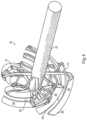
Figure 3 , there is shown a negative image view of fluid passages withinrotor body 34. In other words, the illustration inFigure 3 shows in solid form features which are actually voids inrotor 30. It can be seen that a plurality ofcoolant supply conduits 62 extend radially outward frommanifold 60 tochannels 80. The arcuate shape ofchannels 80 is also readily apparent inFigure 3 . It can also be seen that some ofconduits 62 branch so as to feed more than onechannel 80. After the coolant passes throughchannels 80, and in the case of a refrigerant potentially changing phase, the coolant will pass throughcoolant exhaust conduits 72 and make its way back toexhaust manifold 70. In theFigure 3 illustration only a relatively small part ofexhaust manifold 70 is visible, and none of it might be visible, asconduit 70 is typically internal or in part internal toconduit 60. Abranch 64 in one ofconduits 62 is shown wheremultiple channels 80 are fed originally by asingle conduit 62 frommanifold 60. Turning also toFigure 4 , there is shown a partial view again including a negative image showing certain features ofrotor 30 in solid form where those features are actually voids or cavities withinrotor body 34. The generally curving nature of some ofexhaust conduits 72, the branching ofexhaust conduits 72, and the axial and circumferential distribution ofexhaust conduits 72 as they extend inwardly tomanifold 70 are readily apparent inFigure 4 . Some of the coolant passage features ofrotor 30 are omitted from theFigure 4 illustration for purposes of clarity. - Referring now to
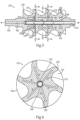
Figure 5 , there is shown a sectioned side view of arotor 132 of similar form torotor 132 ofFigure 1 and accordingly illustrated with the same reference numerals.Rotor 132 includes a plurality ofhelical lobes 135 in an alternating arrangement withhelical grooves 137, axially advancing along arotor body 134.Rotor 132 may be of a female rotor form, wheregrooves 137 andlobes 135 are structured to enmesh with counterpart male lobes and grooves as inrotor 30, and wherelobes 135 are undercut approximately as shown inFigure 5 .Rotor 132 also includes a manifold 160 for supply of coolant, and acoolant exhaust manifold 170. A plurality ofcoolant supply conduits 162 convey coolant frommanifold 160 tochannels 180 wherein heat exchange surfaces 138 are located, generally analogous torotor 30.Exhaust conduits 172 are structured to convey coolant fromchannels 180 toexhaust conduit 170, and thenceforth out ofrotor 132 such as for cooling compression and recirculation. -
Rotor 132 as inFigure 5 has certain similarities withrotor 30 discussed above, but certain differences. Referring now toFigure 6 , there is shown a sectioned view taken along line 6-6 ofFigure 5 whereincoolant supply conduits 162 are shown extending radially outward fromsupply manifold 160. In the view ofFigure 6 it can be seen thatmanifold 160 extends aroundmanifold 170. The particular sectioned view ofFigure 6 extends also throughexhaust conduits 172. It will thus be understood that channels or the like 180 extend betweenconduits 162 andconduits 172.Channels 180 may each be curved between an inlet end fed by asupply conduit 162 and an outlet end feeding anexhaust conduit 172. Referring also toFigure 7 , there is shown a sectioned view taken along line 7-7 ofFigure 5 .Channels 180 are evident inFigure 7 , and shown being fed via coolant withconduits 162. Narrowing ofconduits 162 at radially outward locations to form spray orifices is also visible. Referring also toFigure 8 , there is shown a sectioned view taken along line 8-8 ofFigure 5 , where it can be seen that tips or ends ofchannels 180 are joined toconduits 172, feeding coolant having exchanged heat withsurfaces 138 intoconduits 172, and thenceforth intomanifold 170 for removal fromrotor 132. -
Operating compressor system 10 andcompressor 12 according to the present disclosure will generally occur analogously in each of the embodiments contemplated herein. Accordingly, the present description ofrotor 30 should be understood to generally apply to any of the rotors contemplated herein.Rotor 30 may be rotated to compress a gas withinhousing 14 via impingement ofouter compression surface 36 on the gas in a generally known manner. During rotating ofrotor 30, coolant may be conveyed intocoolant manifold 60 withinrotor 30, and frommanifold 60 tocoolant supply conduits 62.Heat exchange surface 38 may be sprayed with coolant fromconduits 62 at a plurality of axially and circumferentially distributed locations, so as to dissipate heat that is generated by the compression of the gas. As noted above, the conveying and spraying may include conveying and spraying a refrigerant in liquid form that undergoes a phase change withinrotor 30, which is then exhausted in gaseous form fromrotor 30. The present disclosure is not limited as such, however, and other coolants and cooling schemes might be used. - The present description is for illustrative purposes only, and should not be construed to narrow the breadth of the present disclosure in any way. Thus, those skilled in the art will appreciate that various modifications might be made to the presently disclosed embodiments without departing from the full and fair scope of the appended claims. Other aspects, features and advantages will be apparent upon an examination of the attached drawings and appended claims.
Claims (15)
- A rotor for a compressor system comprising:a rotor body (134) defining a longitudinal axis extending between a first axial body end and a second axial body end, the rotor body having an axial direction associated with the longitudinal axis and a circumferential direction associated with a rotating motion about the longitudinal axis, and including an outer compression surface, a plurality of inner heat exchange surfaces (138), and an outer body wall extending between the outer compression surface and the plurality of inner heat exchange surfaces;the rotor body (134) further including a coolant inlet formed in the first axial body end, a coolant outlet formed in the second axial body end, and a coolant manifold (160) fluidly connected with the coolant inlet;the rotor body (134) further including a plurality of coolant supply conduits (162) having an axial and circumferential distribution, and extending outwardly from the coolant manifold (160) so as to supply a coolant to the plurality of inner heat exchange surfaces (138) at a plurality of axial and circumferential locations; andthe rotor body (134) including a plurality of coolant exhaust conduits (172) each coupled with individual ones of the plurality of inner heat exchange surfaces (138), wherein flow paths are defined through pairings of the plurality of coolant supply conduits (162), plurality of inner heat exchange surfaces, and plurality of coolant exhaust conduits where the plurality of inner heat exchange surfaces extend between the plurality of coolant supply conduits and the plurality of coolant exhaust conduits.
- The rotor of claim 1 wherein each of the first and second axial body ends includes a cylindrical shaft end, for rotatably journaling the rotor body (134) in a compressor housing , and the outer compression surface extends axially between the first and second axial body ends and defining a helical shape.
- The rotor of claim 2 wherein the plurality of inner heat exchange surfaces (138) includes a plurality of axially and circumferentially advancing heat exchange surfaces each having an arcuate shape; orwherein the coolant manifold (160) and plurality of coolant supply conduits (162) are formed in a one-piece section of the rotor body (134) having a uniform material composition throughout; orcomprising a screw rotor where the outer compression surface includes a plurality of helical lobes (135) in an alternating arrangement with a plurality of helical grooves (137).
- The rotor of claim 1 wherein the coolant manifold (160) includes a coolant supply manifold, and further comprising a coolant exhaust manifold (170) overlapping in axial extent with the coolant supply manifold, and the plurality of coolant exhaust conduits (172) have an axial and circumferential distribution and extend inwardly to the coolant exhaust manifold.
- The rotor of claim 4 wherein some of the coolant supply conduits (162) are positioned axially between coolant exhaust conduits (172) and the coolant outlet, and some of the coolant exhaust conduits are positioned axially between coolant supply conduits and the coolant inlet; or
wherein at least some of the coolant supply conduits (162) pass through the coolant exhaust manifold (170). - A compressor system comprising:a housing (22) having formed therein a gas inlet (24), a gas outlet (26), and a fluid conduit (28) extending between the gas inlet and the gas outlet; andthe rotor of claim 1 rotatable within the housing (22) about the longitudinal axis, wherein the outer compression surface is exposed to the fluid conduit (28).
- The system of claim 6 wherein the coolant manifold (160) and the plurality of coolant supply conduits (162) are formed in a one-piece section of the rotor body (134).
- The system of claim 6 wherein the coolant manifold (160) includes a coolant supply manifold, and the rotor (132) further includes a coolant exhaust manifold (170).
- The system of claim 8 wherein the plurality of coolant exhaust conduits (172) have an axial and circumferential distribution and extend inwardly to the coolant exhaust manifold (170).
- The system of claim 9 wherein the coolant supply manifold (160) and the coolant exhaust manifold (170) are overlapping in axial extent; and
wherein the coolant supply manifold (160) and the coolant exhaust manifold (170) are in particular coaxial. - The system of claim 6 wherein the outer compression surface forms a helical shape; and
wherein the system in particular includes a dual rotary screw compressor (12) comprising a second rotor in parallel with the first rotor (132) and intermeshed therewith. - The system of claim 6 wherein the plurality of coolant supply conduits (162) include terminal nozzle orifices oriented to spray coolant onto the plurality of inner heat exchange surfaces (138).
- A method of operating a fluid compressor comprising:rotating a rotor (132) within a compressor housing (22) so as to compress a gas via impingement of an outer compression surface of the rotor on the gas, the rotor having an axial direction associated with an axis of rotation about which the rotor is rotated and a circumferential direction associated with rotating the rotor about the axis of rotation;conveying a coolant into a coolant manifold (160) within the rotor (132), and from the manifold to coolant supply conduits (162) within the rotor; andspraying a plurality of inner heat exchange surfaces (138) of the rotor (132) with the coolant from the coolant supply conduits (162) at a plurality of axially and circumferentially distributed locations, so as to dissipate heat generated by the compression of the gas; andwherein the conveying and spraying includes conveying and spraying a refrigerant in liquid form that undergoes a phase change within the rotor (132), and further comprising exhausting the refrigerant in gaseous form from the rotor.
- The method of claim 13 wherein the exhausting of the refrigerant includes exhausting the refrigerant via a coolant exhaust manifold (170) that has an axial extent overlapping with an axial extent of a coolant supply manifold (160) supplying the plurality of coolant supply conduits (162).
- The method of claim 13 which further includes flowing coolant through distinct flow paths defined by individual ones of the plurality of coolant supply conduits (162), plurality of inner heat exchange surfaces (138), and individual ones of a plurality of coolant exhaust conduits (172) where the plurality of inner heat exchange surfaces extend between the plurality of coolant supply conduits and the plurality of coolant exhaust conduits, and wherein the plurality of coolant exhaust conduits have an axial and circumferential distribution and extend inwardly to a coolant exhaust manifold (170).
Applications Claiming Priority (1)
| Application Number | Priority Date | Filing Date | Title |
|---|---|---|---|
| US14/837,945 US9683569B2 (en) | 2015-08-27 | 2015-08-27 | Compressor system having rotor with distributed coolant conduits and method |
Publications (2)
| Publication Number | Publication Date |
|---|---|
| EP3135862A1 EP3135862A1 (en) | 2017-03-01 |
| EP3135862B1 true EP3135862B1 (en) | 2024-07-10 |
Family
ID=56888925
Family Applications (1)
| Application Number | Title | Priority Date | Filing Date |
|---|---|---|---|
| EP16185303.1A Active EP3135862B1 (en) | 2015-08-27 | 2016-08-23 | Compressor system having rotor with distributed coolant conduits and method |
Country Status (3)
| Country | Link |
|---|---|
| US (1) | US9683569B2 (en) |
| EP (1) | EP3135862B1 (en) |
| CN (1) | CN106640640B (en) |
Families Citing this family (11)
| Publication number | Priority date | Publication date | Assignee | Title |
|---|---|---|---|---|
| US10495090B2 (en) * | 2015-08-27 | 2019-12-03 | Ingersoll-Rand Company | Rotor for a compressor system having internal coolant manifold |
| US11047387B2 (en) * | 2017-09-27 | 2021-06-29 | Johnson Controls Technology Company | Rotor for a compressor |
| JP7141459B2 (en) * | 2018-08-29 | 2022-09-22 | 株式会社日立産機システム | Screw rotor and screw fluid machine body |
| US11635262B2 (en) * | 2018-12-20 | 2023-04-25 | Deere & Company | Rotary heat exchanger and system thereof |
| IT201900014916A1 (en) * | 2019-08-22 | 2021-02-22 | Vhit Spa | PUMP |
| CN112594189A (en) * | 2020-12-14 | 2021-04-02 | 珠海格力节能环保制冷技术研究中心有限公司 | Heat abstractor, compressor and heat transfer system |
| US12203386B2 (en) * | 2022-02-18 | 2025-01-21 | Rtx Corporation | Compressor-turbine rotating assembly with integral cooling circuit(s) |
| CN114607604B (en) * | 2022-03-15 | 2024-11-22 | 江苏华瑞制冷设备有限公司 | A low energy consumption screw gas compressor |
| CN117052662A (en) * | 2023-08-17 | 2023-11-14 | 威鹏晟(山东)机械有限公司 | External balance type screw vacuum pump |
| US12385500B1 (en) | 2024-07-03 | 2025-08-12 | Hamilton Sundstrand Corporation | Addtively manufactured bi-metal integral shaft and motor rotor heat exchanger and tie rod for ram air fan |
| CN120273902B (en) * | 2025-06-10 | 2025-08-01 | 上海诺通新能源科技有限公司 | Compressor and compression system |
Family Cites Families (20)
| Publication number | Priority date | Publication date | Assignee | Title |
|---|---|---|---|---|
| US2325617A (en) | 1938-01-13 | 1943-08-03 | Jarvis C Marble | Rotor |
| BE481609A (en) | 1947-04-03 | |||
| US2801792A (en) | 1949-09-15 | 1957-08-06 | Svenska Rotor Maskiner Ab | Cooling of machine structures |
| GB690185A (en) | 1949-09-15 | 1953-04-15 | Ljungstroms Angturbin Ab | Improvements in or relating to the cooling of rotary compressors or motors |
| US2714314A (en) | 1951-05-15 | 1955-08-02 | Howden James & Co Ltd | Rotors for rotary gas compressors and motors |
| DE1021530B (en) | 1955-01-17 | 1957-12-27 | Leybolds Nachfolger E | Rotary piston blower |
| US2918209A (en) | 1957-05-14 | 1959-12-22 | Schueller Otto | Motor-compressor unit |
| SE315444B (en) | 1965-05-14 | 1969-09-29 | A Lysholm | |
| GB1530898A (en) * | 1974-10-29 | 1978-11-01 | Svenska Rotor Maskiner Ab | Rotary positive-displacement internal-combustion engine |
| US5772418A (en) | 1995-04-07 | 1998-06-30 | Tochigi Fuji Sangyo Kabushiki Kaisha | Screw type compressor rotor, rotor casting core and method of manufacturing the rotor |
| US6045343A (en) | 1998-01-15 | 2000-04-04 | Sunny King Machinery Co., Ltd. | Internally cooling rotary compression equipment |
| EP1026399A1 (en) | 1999-02-08 | 2000-08-09 | Ateliers Busch S.A. | Twin feed screw |
| DE19963172A1 (en) | 1999-12-27 | 2001-06-28 | Leybold Vakuum Gmbh | Screw-type vacuum pump has shaft-mounted rotors each with central hollow chamber in which are located built-in components rotating with rotor and forming relatively narrow annular gap through which flows cooling medium |
| JP4955558B2 (en) | 2004-09-02 | 2012-06-20 | エドワーズ リミテッド | Pump rotor cooling |
| GB0419514D0 (en) * | 2004-09-02 | 2004-10-06 | Boc Group Plc | Cooling of pump rotors |
| US7793516B2 (en) * | 2006-09-29 | 2010-09-14 | Lenovo (Singapore) Pte. Ltd. | Rotary compressor with fluidic passages in rotor |
| BE1017371A3 (en) | 2006-11-23 | 2008-07-01 | Atlas Copco Airpower Nv | ROTOR AND COMPRESSOR ELEMENT FITTED WITH SUCH ROTOR. |
| US7993118B2 (en) | 2007-06-26 | 2011-08-09 | GM Global Technology Operations LLC | Liquid-cooled rotor assembly for a supercharger |
| CN102242711B (en) | 2011-07-05 | 2014-01-01 | 山东省临风鼓风机有限公司 | High-temperature resistant high-pressure-rise type Roots blower |
| US11359632B2 (en) * | 2014-10-31 | 2022-06-14 | Ingersoll-Rand Industrial U.S., Inc. | Rotary screw compressor rotor having work extraction mechanism |
-
2015
- 2015-08-27 US US14/837,945 patent/US9683569B2/en active Active
-
2016
- 2016-08-23 EP EP16185303.1A patent/EP3135862B1/en active Active
- 2016-08-26 CN CN201610730438.4A patent/CN106640640B/en active Active
Also Published As
| Publication number | Publication date |
|---|---|
| EP3135862A1 (en) | 2017-03-01 |
| CN106640640B (en) | 2019-11-08 |
| US20170058896A1 (en) | 2017-03-02 |
| CN106640640A (en) | 2017-05-10 |
| US9683569B2 (en) | 2017-06-20 |
Similar Documents
| Publication | Publication Date | Title |
|---|---|---|
| US9683569B2 (en) | Compressor system having rotor with distributed coolant conduits and method | |
| EP3135863B1 (en) | Rotor for a compressor system having internal coolant manifold | |
| CN102577056B (en) | Refrigerant supply and discharge device for superconducting rotating electric machine and superconducting rotating electric machine provided with the refrigerant supply and discharge device | |
| EP2665936B1 (en) | Pump with a stator arrangement comprising a first part and a second part | |
| US7993118B2 (en) | Liquid-cooled rotor assembly for a supercharger | |
| CN113785146B (en) | Especially for sliding ring seal components and pump components for thermal media | |
| US12209587B2 (en) | Element, device and method for compressing gas to be compressed having a low temperature | |
| US12378961B2 (en) | Screw pump with a tapered suction-side section and a pressure-side section with a decreasing clearance | |
| US7963744B2 (en) | Cooling of pump rotors | |
| EP3467315B1 (en) | Screw compressor with oil injection at multiple volume ratios | |
| CN217107442U (en) | Element and device for compressing a cryogenic gas to be compressed | |
| CN100473838C (en) | Cooling of pump rotors | |
| JP2022535543A (en) | Bearing with pads having cooling microchannels therein, and method | |
| US20240209752A1 (en) | Lubrication of bearings of a turbomachine shaft |
Legal Events
| Date | Code | Title | Description |
|---|---|---|---|
| PUAI | Public reference made under article 153(3) epc to a published international application that has entered the european phase |
Free format text: ORIGINAL CODE: 0009012 |
|
| STAA | Information on the status of an ep patent application or granted ep patent |
Free format text: STATUS: REQUEST FOR EXAMINATION WAS MADE |
|
| 17P | Request for examination filed |
Effective date: 20160823 |
|
| AK | Designated contracting states |
Kind code of ref document: A1 Designated state(s): AL AT BE BG CH CY CZ DE DK EE ES FI FR GB GR HR HU IE IS IT LI LT LU LV MC MK MT NL NO PL PT RO RS SE SI SK SM TR |
|
| AX | Request for extension of the european patent |
Extension state: BA ME |
|
| RAP1 | Party data changed (applicant data changed or rights of an application transferred) |
Owner name: INGERSOLL-RAND INDUSTRIAL U.S., INC. |
|
| STAA | Information on the status of an ep patent application or granted ep patent |
Free format text: STATUS: EXAMINATION IS IN PROGRESS |
|
| 17Q | First examination report despatched |
Effective date: 20210322 |
|
| GRAP | Despatch of communication of intention to grant a patent |
Free format text: ORIGINAL CODE: EPIDOSNIGR1 |
|
| STAA | Information on the status of an ep patent application or granted ep patent |
Free format text: STATUS: GRANT OF PATENT IS INTENDED |
|
| INTG | Intention to grant announced |
Effective date: 20240216 |
|
| GRAS | Grant fee paid |
Free format text: ORIGINAL CODE: EPIDOSNIGR3 |
|
| GRAA | (expected) grant |
Free format text: ORIGINAL CODE: 0009210 |
|
| STAA | Information on the status of an ep patent application or granted ep patent |
Free format text: STATUS: THE PATENT HAS BEEN GRANTED |
|
| AK | Designated contracting states |
Kind code of ref document: B1 Designated state(s): AL AT BE BG CH CY CZ DE DK EE ES FI FR GB GR HR HU IE IS IT LI LT LU LV MC MK MT NL NO PL PT RO RS SE SI SK SM TR |
|
| REG | Reference to a national code |
Ref country code: CH Ref legal event code: EP |
|
| REG | Reference to a national code |
Ref country code: DE Ref legal event code: R096 Ref document number: 602016088316 Country of ref document: DE |
|
| REG | Reference to a national code |
Ref country code: LT Ref legal event code: MG9D |
|
| REG | Reference to a national code |
Ref country code: NL Ref legal event code: MP Effective date: 20240710 |
|
| PG25 | Lapsed in a contracting state [announced via postgrant information from national office to epo] |
Ref country code: PT Free format text: LAPSE BECAUSE OF FAILURE TO SUBMIT A TRANSLATION OF THE DESCRIPTION OR TO PAY THE FEE WITHIN THE PRESCRIBED TIME-LIMIT Effective date: 20241111 |
|
| REG | Reference to a national code |
Ref country code: AT Ref legal event code: MK05 Ref document number: 1702186 Country of ref document: AT Kind code of ref document: T Effective date: 20240710 |
|
| PG25 | Lapsed in a contracting state [announced via postgrant information from national office to epo] |
Ref country code: NL Free format text: LAPSE BECAUSE OF FAILURE TO SUBMIT A TRANSLATION OF THE DESCRIPTION OR TO PAY THE FEE WITHIN THE PRESCRIBED TIME-LIMIT Effective date: 20240710 |
|
| PG25 | Lapsed in a contracting state [announced via postgrant information from national office to epo] |
Ref country code: PT Free format text: LAPSE BECAUSE OF FAILURE TO SUBMIT A TRANSLATION OF THE DESCRIPTION OR TO PAY THE FEE WITHIN THE PRESCRIBED TIME-LIMIT Effective date: 20241111 Ref country code: NL Free format text: LAPSE BECAUSE OF FAILURE TO SUBMIT A TRANSLATION OF THE DESCRIPTION OR TO PAY THE FEE WITHIN THE PRESCRIBED TIME-LIMIT Effective date: 20240710 |
|
| PG25 | Lapsed in a contracting state [announced via postgrant information from national office to epo] |
Ref country code: NO Free format text: LAPSE BECAUSE OF FAILURE TO SUBMIT A TRANSLATION OF THE DESCRIPTION OR TO PAY THE FEE WITHIN THE PRESCRIBED TIME-LIMIT Effective date: 20241010 |
|
| PG25 | Lapsed in a contracting state [announced via postgrant information from national office to epo] |
Ref country code: FI Free format text: LAPSE BECAUSE OF FAILURE TO SUBMIT A TRANSLATION OF THE DESCRIPTION OR TO PAY THE FEE WITHIN THE PRESCRIBED TIME-LIMIT Effective date: 20240710 Ref country code: GR Free format text: LAPSE BECAUSE OF FAILURE TO SUBMIT A TRANSLATION OF THE DESCRIPTION OR TO PAY THE FEE WITHIN THE PRESCRIBED TIME-LIMIT Effective date: 20241011 Ref country code: PL Free format text: LAPSE BECAUSE OF FAILURE TO SUBMIT A TRANSLATION OF THE DESCRIPTION OR TO PAY THE FEE WITHIN THE PRESCRIBED TIME-LIMIT Effective date: 20240710 |
|
| PG25 | Lapsed in a contracting state [announced via postgrant information from national office to epo] |
Ref country code: BG Free format text: LAPSE BECAUSE OF FAILURE TO SUBMIT A TRANSLATION OF THE DESCRIPTION OR TO PAY THE FEE WITHIN THE PRESCRIBED TIME-LIMIT Effective date: 20240710 |
|
| PG25 | Lapsed in a contracting state [announced via postgrant information from national office to epo] |
Ref country code: LV Free format text: LAPSE BECAUSE OF FAILURE TO SUBMIT A TRANSLATION OF THE DESCRIPTION OR TO PAY THE FEE WITHIN THE PRESCRIBED TIME-LIMIT Effective date: 20240710 |
|
| PG25 | Lapsed in a contracting state [announced via postgrant information from national office to epo] |
Ref country code: AT Free format text: LAPSE BECAUSE OF FAILURE TO SUBMIT A TRANSLATION OF THE DESCRIPTION OR TO PAY THE FEE WITHIN THE PRESCRIBED TIME-LIMIT Effective date: 20240710 Ref country code: IS Free format text: LAPSE BECAUSE OF FAILURE TO SUBMIT A TRANSLATION OF THE DESCRIPTION OR TO PAY THE FEE WITHIN THE PRESCRIBED TIME-LIMIT Effective date: 20241110 |
|
| PG25 | Lapsed in a contracting state [announced via postgrant information from national office to epo] |
Ref country code: HR Free format text: LAPSE BECAUSE OF FAILURE TO SUBMIT A TRANSLATION OF THE DESCRIPTION OR TO PAY THE FEE WITHIN THE PRESCRIBED TIME-LIMIT Effective date: 20240710 |
|
| PG25 | Lapsed in a contracting state [announced via postgrant information from national office to epo] |
Ref country code: RS Free format text: LAPSE BECAUSE OF FAILURE TO SUBMIT A TRANSLATION OF THE DESCRIPTION OR TO PAY THE FEE WITHIN THE PRESCRIBED TIME-LIMIT Effective date: 20241010 Ref country code: ES Free format text: LAPSE BECAUSE OF FAILURE TO SUBMIT A TRANSLATION OF THE DESCRIPTION OR TO PAY THE FEE WITHIN THE PRESCRIBED TIME-LIMIT Effective date: 20240710 |
|
| PG25 | Lapsed in a contracting state [announced via postgrant information from national office to epo] |
Ref country code: RS Free format text: LAPSE BECAUSE OF FAILURE TO SUBMIT A TRANSLATION OF THE DESCRIPTION OR TO PAY THE FEE WITHIN THE PRESCRIBED TIME-LIMIT Effective date: 20241010 Ref country code: PL Free format text: LAPSE BECAUSE OF FAILURE TO SUBMIT A TRANSLATION OF THE DESCRIPTION OR TO PAY THE FEE WITHIN THE PRESCRIBED TIME-LIMIT Effective date: 20240710 Ref country code: NO Free format text: LAPSE BECAUSE OF FAILURE TO SUBMIT A TRANSLATION OF THE DESCRIPTION OR TO PAY THE FEE WITHIN THE PRESCRIBED TIME-LIMIT Effective date: 20241010 Ref country code: LV Free format text: LAPSE BECAUSE OF FAILURE TO SUBMIT A TRANSLATION OF THE DESCRIPTION OR TO PAY THE FEE WITHIN THE PRESCRIBED TIME-LIMIT Effective date: 20240710 Ref country code: IS Free format text: LAPSE BECAUSE OF FAILURE TO SUBMIT A TRANSLATION OF THE DESCRIPTION OR TO PAY THE FEE WITHIN THE PRESCRIBED TIME-LIMIT Effective date: 20241110 Ref country code: HR Free format text: LAPSE BECAUSE OF FAILURE TO SUBMIT A TRANSLATION OF THE DESCRIPTION OR TO PAY THE FEE WITHIN THE PRESCRIBED TIME-LIMIT Effective date: 20240710 Ref country code: GR Free format text: LAPSE BECAUSE OF FAILURE TO SUBMIT A TRANSLATION OF THE DESCRIPTION OR TO PAY THE FEE WITHIN THE PRESCRIBED TIME-LIMIT Effective date: 20241011 Ref country code: FI Free format text: LAPSE BECAUSE OF FAILURE TO SUBMIT A TRANSLATION OF THE DESCRIPTION OR TO PAY THE FEE WITHIN THE PRESCRIBED TIME-LIMIT Effective date: 20240710 Ref country code: ES Free format text: LAPSE BECAUSE OF FAILURE TO SUBMIT A TRANSLATION OF THE DESCRIPTION OR TO PAY THE FEE WITHIN THE PRESCRIBED TIME-LIMIT Effective date: 20240710 Ref country code: BG Free format text: LAPSE BECAUSE OF FAILURE TO SUBMIT A TRANSLATION OF THE DESCRIPTION OR TO PAY THE FEE WITHIN THE PRESCRIBED TIME-LIMIT Effective date: 20240710 Ref country code: AT Free format text: LAPSE BECAUSE OF FAILURE TO SUBMIT A TRANSLATION OF THE DESCRIPTION OR TO PAY THE FEE WITHIN THE PRESCRIBED TIME-LIMIT Effective date: 20240710 |
|
| REG | Reference to a national code |
Ref country code: CH Ref legal event code: PL |
|
| REG | Reference to a national code |
Ref country code: DE Ref legal event code: R097 Ref document number: 602016088316 Country of ref document: DE |
|
| PG25 | Lapsed in a contracting state [announced via postgrant information from national office to epo] |
Ref country code: RO Free format text: LAPSE BECAUSE OF FAILURE TO SUBMIT A TRANSLATION OF THE DESCRIPTION OR TO PAY THE FEE WITHIN THE PRESCRIBED TIME-LIMIT Effective date: 20240710 Ref country code: DK Free format text: LAPSE BECAUSE OF FAILURE TO SUBMIT A TRANSLATION OF THE DESCRIPTION OR TO PAY THE FEE WITHIN THE PRESCRIBED TIME-LIMIT Effective date: 20240710 Ref country code: SM Free format text: LAPSE BECAUSE OF FAILURE TO SUBMIT A TRANSLATION OF THE DESCRIPTION OR TO PAY THE FEE WITHIN THE PRESCRIBED TIME-LIMIT Effective date: 20240710 |
|
| PG25 | Lapsed in a contracting state [announced via postgrant information from national office to epo] |
Ref country code: LU Free format text: LAPSE BECAUSE OF NON-PAYMENT OF DUE FEES Effective date: 20240823 |
|
| PG25 | Lapsed in a contracting state [announced via postgrant information from national office to epo] |
Ref country code: CH Free format text: LAPSE BECAUSE OF NON-PAYMENT OF DUE FEES Effective date: 20240831 Ref country code: MC Free format text: LAPSE BECAUSE OF FAILURE TO SUBMIT A TRANSLATION OF THE DESCRIPTION OR TO PAY THE FEE WITHIN THE PRESCRIBED TIME-LIMIT Effective date: 20240710 Ref country code: EE Free format text: LAPSE BECAUSE OF FAILURE TO SUBMIT A TRANSLATION OF THE DESCRIPTION OR TO PAY THE FEE WITHIN THE PRESCRIBED TIME-LIMIT Effective date: 20240710 |
|
| PG25 | Lapsed in a contracting state [announced via postgrant information from national office to epo] |
Ref country code: CZ Free format text: LAPSE BECAUSE OF FAILURE TO SUBMIT A TRANSLATION OF THE DESCRIPTION OR TO PAY THE FEE WITHIN THE PRESCRIBED TIME-LIMIT Effective date: 20240710 |
|
| PG25 | Lapsed in a contracting state [announced via postgrant information from national office to epo] |
Ref country code: SK Free format text: LAPSE BECAUSE OF FAILURE TO SUBMIT A TRANSLATION OF THE DESCRIPTION OR TO PAY THE FEE WITHIN THE PRESCRIBED TIME-LIMIT Effective date: 20240710 |
|
| PLBE | No opposition filed within time limit |
Free format text: ORIGINAL CODE: 0009261 |
|
| STAA | Information on the status of an ep patent application or granted ep patent |
Free format text: STATUS: NO OPPOSITION FILED WITHIN TIME LIMIT |
|
| 26N | No opposition filed |
Effective date: 20250411 |
|
| REG | Reference to a national code |
Ref country code: BE Ref legal event code: MM Effective date: 20240831 |
|
| PG25 | Lapsed in a contracting state [announced via postgrant information from national office to epo] |
Ref country code: BE Free format text: LAPSE BECAUSE OF NON-PAYMENT OF DUE FEES Effective date: 20240831 |
|
| PG25 | Lapsed in a contracting state [announced via postgrant information from national office to epo] |
Ref country code: IE Free format text: LAPSE BECAUSE OF NON-PAYMENT OF DUE FEES Effective date: 20240823 |
|
| PG25 | Lapsed in a contracting state [announced via postgrant information from national office to epo] |
Ref country code: SE Free format text: LAPSE BECAUSE OF FAILURE TO SUBMIT A TRANSLATION OF THE DESCRIPTION OR TO PAY THE FEE WITHIN THE PRESCRIBED TIME-LIMIT Effective date: 20240710 |
|
| PGFP | Annual fee paid to national office [announced via postgrant information from national office to epo] |
Ref country code: DE Payment date: 20250828 Year of fee payment: 10 |
|
| PGFP | Annual fee paid to national office [announced via postgrant information from national office to epo] |
Ref country code: IT Payment date: 20250826 Year of fee payment: 10 |
|
| PGFP | Annual fee paid to national office [announced via postgrant information from national office to epo] |
Ref country code: GB Payment date: 20250829 Year of fee payment: 10 |
|
| PGFP | Annual fee paid to national office [announced via postgrant information from national office to epo] |
Ref country code: FR Payment date: 20250828 Year of fee payment: 10 |
|
| PG25 | Lapsed in a contracting state [announced via postgrant information from national office to epo] |
Ref country code: CY Free format text: LAPSE BECAUSE OF FAILURE TO SUBMIT A TRANSLATION OF THE DESCRIPTION OR TO PAY THE FEE WITHIN THE PRESCRIBED TIME-LIMIT; INVALID AB INITIO Effective date: 20160823 |
|
| PG25 | Lapsed in a contracting state [announced via postgrant information from national office to epo] |
Ref country code: HU Free format text: LAPSE BECAUSE OF FAILURE TO SUBMIT A TRANSLATION OF THE DESCRIPTION OR TO PAY THE FEE WITHIN THE PRESCRIBED TIME-LIMIT; INVALID AB INITIO Effective date: 20160823 |