EP3135734A1 - Mechanically robust linked particle networks - Google Patents
Mechanically robust linked particle networks Download PDFInfo
- Publication number
- EP3135734A1 EP3135734A1 EP16184778.5A EP16184778A EP3135734A1 EP 3135734 A1 EP3135734 A1 EP 3135734A1 EP 16184778 A EP16184778 A EP 16184778A EP 3135734 A1 EP3135734 A1 EP 3135734A1
- Authority
- EP
- European Patent Office
- Prior art keywords
- particles
- linked
- anisotropic
- sheets
- network
- Prior art date
- Legal status (The legal status is an assumption and is not a legal conclusion. Google has not performed a legal analysis and makes no representation as to the accuracy of the status listed.)
- Granted
Links
Images




Classifications
-
- C—CHEMISTRY; METALLURGY
- C08—ORGANIC MACROMOLECULAR COMPOUNDS; THEIR PREPARATION OR CHEMICAL WORKING-UP; COMPOSITIONS BASED THEREON
- C08F—MACROMOLECULAR COMPOUNDS OBTAINED BY REACTIONS ONLY INVOLVING CARBON-TO-CARBON UNSATURATED BONDS
- C08F292/00—Macromolecular compounds obtained by polymerising monomers on to inorganic materials
-
- C—CHEMISTRY; METALLURGY
- C08—ORGANIC MACROMOLECULAR COMPOUNDS; THEIR PREPARATION OR CHEMICAL WORKING-UP; COMPOSITIONS BASED THEREON
- C08J—WORKING-UP; GENERAL PROCESSES OF COMPOUNDING; AFTER-TREATMENT NOT COVERED BY SUBCLASSES C08B, C08C, C08F, C08G or C08H
- C08J3/00—Processes of treating or compounding macromolecular substances
- C08J3/28—Treatment by wave energy or particle radiation
-
- C—CHEMISTRY; METALLURGY
- C01—INORGANIC CHEMISTRY
- C01B—NON-METALLIC ELEMENTS; COMPOUNDS THEREOF; METALLOIDS OR COMPOUNDS THEREOF NOT COVERED BY SUBCLASS C01C
- C01B13/00—Oxygen; Ozone; Oxides or hydroxides in general
- C01B13/14—Methods for preparing oxides or hydroxides in general
- C01B13/145—After-treatment of oxides or hydroxides, e.g. pulverising, drying, decreasing the acidity
-
- C—CHEMISTRY; METALLURGY
- C01—INORGANIC CHEMISTRY
- C01B—NON-METALLIC ELEMENTS; COMPOUNDS THEREOF; METALLOIDS OR COMPOUNDS THEREOF NOT COVERED BY SUBCLASS C01C
- C01B32/00—Carbon; Compounds thereof
- C01B32/15—Nano-sized carbon materials
- C01B32/182—Graphene
- C01B32/194—After-treatment
- C01B32/196—Purification
-
- C—CHEMISTRY; METALLURGY
- C08—ORGANIC MACROMOLECULAR COMPOUNDS; THEIR PREPARATION OR CHEMICAL WORKING-UP; COMPOSITIONS BASED THEREON
- C08G—MACROMOLECULAR COMPOUNDS OBTAINED OTHERWISE THAN BY REACTIONS ONLY INVOLVING UNSATURATED CARBON-TO-CARBON BONDS
- C08G59/00—Polycondensates containing more than one epoxy group per molecule; Macromolecules obtained by polymerising compounds containing more than one epoxy group per molecule using curing agents or catalysts which react with the epoxy groups
-
- C—CHEMISTRY; METALLURGY
- C08—ORGANIC MACROMOLECULAR COMPOUNDS; THEIR PREPARATION OR CHEMICAL WORKING-UP; COMPOSITIONS BASED THEREON
- C08G—MACROMOLECULAR COMPOUNDS OBTAINED OTHERWISE THAN BY REACTIONS ONLY INVOLVING UNSATURATED CARBON-TO-CARBON BONDS
- C08G69/00—Macromolecular compounds obtained by reactions forming a carboxylic amide link in the main chain of the macromolecule
-
- C—CHEMISTRY; METALLURGY
- C08—ORGANIC MACROMOLECULAR COMPOUNDS; THEIR PREPARATION OR CHEMICAL WORKING-UP; COMPOSITIONS BASED THEREON
- C08G—MACROMOLECULAR COMPOUNDS OBTAINED OTHERWISE THAN BY REACTIONS ONLY INVOLVING UNSATURATED CARBON-TO-CARBON BONDS
- C08G69/00—Macromolecular compounds obtained by reactions forming a carboxylic amide link in the main chain of the macromolecule
- C08G69/02—Polyamides derived from amino-carboxylic acids or from polyamines and polycarboxylic acids
-
- C—CHEMISTRY; METALLURGY
- C08—ORGANIC MACROMOLECULAR COMPOUNDS; THEIR PREPARATION OR CHEMICAL WORKING-UP; COMPOSITIONS BASED THEREON
- C08G—MACROMOLECULAR COMPOUNDS OBTAINED OTHERWISE THAN BY REACTIONS ONLY INVOLVING UNSATURATED CARBON-TO-CARBON BONDS
- C08G71/00—Macromolecular compounds obtained by reactions forming a ureide or urethane link, otherwise, than from isocyanate radicals in the main chain of the macromolecule
- C08G71/02—Polyureas
-
- C—CHEMISTRY; METALLURGY
- C08—ORGANIC MACROMOLECULAR COMPOUNDS; THEIR PREPARATION OR CHEMICAL WORKING-UP; COMPOSITIONS BASED THEREON
- C08G—MACROMOLECULAR COMPOUNDS OBTAINED OTHERWISE THAN BY REACTIONS ONLY INVOLVING UNSATURATED CARBON-TO-CARBON BONDS
- C08G83/00—Macromolecular compounds not provided for in groups C08G2/00 - C08G81/00
- C08G83/001—Macromolecular compounds containing organic and inorganic sequences, e.g. organic polymers grafted onto silica
-
- C—CHEMISTRY; METALLURGY
- C08—ORGANIC MACROMOLECULAR COMPOUNDS; THEIR PREPARATION OR CHEMICAL WORKING-UP; COMPOSITIONS BASED THEREON
- C08K—Use of inorganic or non-macromolecular organic substances as compounding ingredients
- C08K3/00—Use of inorganic substances as compounding ingredients
- C08K3/02—Elements
- C08K3/04—Carbon
- C08K3/042—Graphene or derivatives, e.g. graphene oxides
-
- C—CHEMISTRY; METALLURGY
- C08—ORGANIC MACROMOLECULAR COMPOUNDS; THEIR PREPARATION OR CHEMICAL WORKING-UP; COMPOSITIONS BASED THEREON
- C08K—Use of inorganic or non-macromolecular organic substances as compounding ingredients
- C08K3/00—Use of inorganic substances as compounding ingredients
- C08K3/34—Silicon-containing compounds
-
- C—CHEMISTRY; METALLURGY
- C08—ORGANIC MACROMOLECULAR COMPOUNDS; THEIR PREPARATION OR CHEMICAL WORKING-UP; COMPOSITIONS BASED THEREON
- C08K—Use of inorganic or non-macromolecular organic substances as compounding ingredients
- C08K7/00—Use of ingredients characterised by shape
-
- C—CHEMISTRY; METALLURGY
- C08—ORGANIC MACROMOLECULAR COMPOUNDS; THEIR PREPARATION OR CHEMICAL WORKING-UP; COMPOSITIONS BASED THEREON
- C08K—Use of inorganic or non-macromolecular organic substances as compounding ingredients
- C08K9/00—Use of pretreated ingredients
- C08K9/04—Ingredients treated with organic substances
- C08K9/06—Ingredients treated with organic substances with silicon-containing compounds
-
- C—CHEMISTRY; METALLURGY
- C08—ORGANIC MACROMOLECULAR COMPOUNDS; THEIR PREPARATION OR CHEMICAL WORKING-UP; COMPOSITIONS BASED THEREON
- C08K—Use of inorganic or non-macromolecular organic substances as compounding ingredients
- C08K9/00—Use of pretreated ingredients
- C08K9/08—Ingredients agglomerated by treatment with a binding agent
-
- C—CHEMISTRY; METALLURGY
- C09—DYES; PAINTS; POLISHES; NATURAL RESINS; ADHESIVES; COMPOSITIONS NOT OTHERWISE PROVIDED FOR; APPLICATIONS OF MATERIALS NOT OTHERWISE PROVIDED FOR
- C09C—TREATMENT OF INORGANIC MATERIALS, OTHER THAN FIBROUS FILLERS, TO ENHANCE THEIR PIGMENTING OR FILLING PROPERTIES ; PREPARATION OF CARBON BLACK ; PREPARATION OF INORGANIC MATERIALS WHICH ARE NO SINGLE CHEMICAL COMPOUNDS AND WHICH ARE MAINLY USED AS PIGMENTS OR FILLERS
- C09C1/00—Treatment of specific inorganic materials other than fibrous fillers; Preparation of carbon black
- C09C1/44—Carbon
-
- C—CHEMISTRY; METALLURGY
- C09—DYES; PAINTS; POLISHES; NATURAL RESINS; ADHESIVES; COMPOSITIONS NOT OTHERWISE PROVIDED FOR; APPLICATIONS OF MATERIALS NOT OTHERWISE PROVIDED FOR
- C09C—TREATMENT OF INORGANIC MATERIALS, OTHER THAN FIBROUS FILLERS, TO ENHANCE THEIR PIGMENTING OR FILLING PROPERTIES ; PREPARATION OF CARBON BLACK ; PREPARATION OF INORGANIC MATERIALS WHICH ARE NO SINGLE CHEMICAL COMPOUNDS AND WHICH ARE MAINLY USED AS PIGMENTS OR FILLERS
- C09C3/00—Treatment in general of inorganic materials, other than fibrous fillers, to enhance their pigmenting or filling properties
- C09C3/08—Treatment with low-molecular-weight non-polymer organic compounds
Definitions
- This disclosure relates to composite materials, more particularly to materials made up of chemically linked and aligned particles.
- the current state of the art involves prepreg long reinforcing fibers embedded into polymer matrices.
- the term 'prepreg' typically refers to fabric reinforcement that has been pre-impregnated with a resin system.
- the resin system generally consists of an epoxy that already includes the proper curing agent.
- Woven carbon fibers and fiberglass fabrics are the materials of choice in the prepreg industry. These materials enable structures with unrivaled mechanical properties, but have many difficulties in fabrication, include being time consuming and somewhat limited in that they can only be made in flat, layered shapes.
- An embodiment comprises a method including functionalizing edges of particles of an anisotropic material, exfoliating of the particles to form sheets of the material, aligning the sheets of material to form a network of multi-layered and aligned particles, and forming a structure out of the network of particles.
- An embodiment comprises a method including functionalizing edges of particles of an anisotropic material, exfoliating the particles to form sheets of the material, aligning the sheets of material to form a network of multi-layered and aligned particles, and forming a structure out of the network of particles.
- Figure 1 shows the difference between current state of the art particle-reinforced composite materials consisting of randomly dispersed particles within a polymer matrix 10, without direct chemical linking between particles, and networks of chemically linked particles 12.
- these particles 10 can move relatively freely together with the polymer parts exposed to stress.
- the mechanical robustness of such composite structures in generally larger than of the same particle-free polymer but the enhancement is limited.
- the chemically linked network of particles as shown at 12 in Figure 1 have restricted movement in impact, therefore providing composite particle structures with increased toughness, elastic modulus and generally with enhanced structural integrity.
- the linked particles can have any shape including using random shape or isotropic (spherical) particles as illustrated in Figure 1 .
- the functionalized particles are anisotropic.
- the particles have functional groups selected in such a way that they can react only in one preferred way to produce aligned networks of linked particles. Generally, these particles will be referred to here as anisotropic particles.
- Anisotropic particles may include platy particles, such as graphene or clays.
- a platy particle typically has a flat and plate like shape oriented horizontally.
- Other anisotropic particles include fibers or rods.
- Suitable platy anisotropic particles include: layered silicate clays, laponite, hydroxyapatite, alumina platelets and graphene and fibers and rods.
- suitable layered silicate include, a layered silicate of kaolinite group such as kaolinite, dickite, halloysite, chrysotile, lizardite, amesite; a layered silicate of smectite group such as montmorillonite, beidellite, nontronite, saponite, iron saponite, hectorite, sauconite, stevensite; a vermiculite group such as dioctahedral vermiculite, and trioctahedral vermiculite; a layered silicate of mica group such as muscovite, paragonite, phlogopite, biotie, and lepidolite; a layered silicate of brittle mica group such as margarite, clinto
- Figure 2 shows an overall process and system 20 for creating robust, chemically linked particle networks.
- the basis of the system consists of reactive particles.
- the anisotropic particles 22 undergo activation at 22, in this case, edge functionalization.
- the edge functionalization may occur due to addition of the particles to some sort of fluid.
- the edge functionalization causes the particles to form edge functionalities shown at 26 which are used later in the process to produce in-plane chemical connections.
- a parallel alignment as show at 36 in Figure 2 can be achieved by appropriate aligning means.
- these aggregates are exfoliated into at 28 into aligned, individual sheets of linked particles at 30.
- the linked particles are aligned inside a nozzle and then the chemical linking is induced, possibly using some external excitation to form a solid cured structure 34.
- the resulting chemically-linked particle network has in-plane an inter-sheet links of aligned particles shown at 36 that provide strength and flexibility nearing if not equal to that of prepreg carbon fibers, without the time-consuming and complex manufacturing process those require.
- these particle networks are 'digitally compatible,' meaning that it is possible to dispense them from a system similar to a print head.
- the nozzle referred to above may be attached to a reservoir of these materials and assists with the alignment of the particles during dispensing.
- edge functionalization As shown in Figure 3 , one embodiment uses graphene.
- the system uses inexpensive graphite powder mixed into 4-aminobenzoic acid (H 2 NC 6 H 4 CO 2 H) to cause edge functionalization at 50.
- the graphite particles then undergo exfoliation at 52, in one embodiment by undergoing sonication in an appropriate solvent.
- the presence of edge functional groups may facilitate the exfoliation.
- Exfoliation as used here generally means the process of turning three dimensional particle sheets into two dimensional sheets. This may be followed by condensation at 54, in this embodiment using an acrylate component.
- the exfoliated amino functionalized graphene sheets are placed in the presence of an appropriate organic linking molecule, then they undergo alignment beyond that caused by the edge functionalization, condensation and exfoliation.
- the nozzle will also dispense the aligned particles to form a desired structure which is cured at 58 by inducing a chemical reaction which links the particles through the organic linking molecules.
- the chemical linker is chosen such as to react directly with the amino functions through a condensation reaction.
- these linkers contain two or more functional groups capable of reacting with amino groups.
- Figure 4 illustrates schematically the type of chemical connectors as a function of the chemical linkers.
- the intermediate vinyl functionalized graphene sheets are cross-linked by a vinyl polymerization reaction.
- the polymerization reaction may proceed directly by bonding of the vinyl groups present onto graphene edges.
- the vinyl functions present onto graphene edges may be co-polymerized with vinyl functional monomers and oligomers. This approach is advantageous because it enables the fabrication of networks with various degrees of flexibility in addition to mechanical strength simply changing the length of the reactive polymer chain.
- This example has discussed only graphene flakes.
- a platy particle one could form chemically-linked particles out of clays shown in Figure 5 .
- the chemistry of clays differs significantly from the chemistry of graphene.
- Layered silicate particles typically possess reactive hydroxyl groups (-OH).
- the present invention takes advantage of these groups for the introduction of suitable chemical linkers.
- vinyl groups are introduced onto the edge of aggregated clay particles by reaction with silane coupling agents 60.
- Silane coupling agents connect to the particle edges through alkoxy groups. This embodiment uses mono-functional silane coupling reagents at 60.
- tri-functional silanes when particles such as clays or silica are being functionalized for dispersion in organic polymers.
- tri-functional silanes typically connect adjacent clay sheets preventing them from separating during exfoliation.
- Mono-alkoxy silanes have only one possible way of linking to clays preventing linking of adjacent clay sheets.
- the possibility of inter-particle linking is provided in this embodiment be the vinyl groups present in the chemical structure of the silane coupling agent.
- Suitable monofunctional silane agents incorporating polymerizable vinyl groups are known. For example methacryloxypropyldimethylethoxy silane and methacryloxypropyldimethylmethoxy silane coupling agents are commercially available at Gelest Inc., Morrisville, PA.
- the functionalized clay sheets are exfoliated in DMF (dimethylformamide) and water mixtures at 62. This will then result in individual sheets of clay which can then be linked in a controlled manner. This may occur in clay-to-clay or clay-to-polymer. This provides enhanced mechanical and gas permeability properties.
- the chemically-linked sheets then align in the nozzle as discussed above at 64. The structures can then be formed at 66.
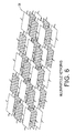
- a further embodiment provides chemically linked networks consisting of intercalated different particles at 68 in Figure 6 .
- Such structures may possess multiple properties provided by the different types of constituent particles. These novel architected structures are very difficult to achieve with present technologies.
- a mixed structure containing graphene and hydroxyapatite linked particles may provide mechanically strong structures (a graphene property) which have excellent gas barrier performance (a hydroxyapatite property) at the same time.
- a typical formulation for this purpose consists of functionalized particles dispersed in a mixture containing a solvent a linking multifunctional component and a curing initiator.
- a solvent is optionally needed in order to achieve workable viscosities for these formulations.
- the linking material is chosen to be reactive under appropriate activating reaction conditions with the functional groups present onto the surface or the edge of the particles.
- epoxy linker precursors create cured epoxy particle composites
- acyl chlorides produce cured Kevlar or Nylon like particle networks
- isocyanates produce polyurea linked particles networks.
- These condensation reactions typically require an acid or a base catalyst.
- Radical polymerization of vinyl groups present onto the particles produce vinyl groups linked particles networks. Radical polymerization required a radical initiator.
- Useful thermal initiators are those which produce initiating radicals by heating. Suitable examples include benzoyl peroxide or azobisisobutyronitrile and their functional derivatives.
- photoinitiators which produce radicals when activated by a specific wavelength light, most often UltraViolet light.
- Type I photoinitiators such as benzoin ethers, benzyl ketals, ⁇ -dialkoxyacetophenones, ⁇ -hydroxyalkylphenones, ⁇ -aminoalkylphenones and acylphosphine oxides and Type II photoinitiators such as benxzophenones and thioxanthones in combination with amine synergists.
- the particles alignment may take many forms.
- the nozzle when the alignment is induced in a nozzle, the nozzle may be one of those disclosed in US Patent Application No. 14/578,071 .
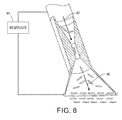
- Figures 7 and 8 disclose embodiments of aligning nozzles.
- Figure 7 an example of a nozzle 70 with a two-roll mill.
- the rollers 74 and 78 rotate in opposite directions.
- a fluid enters the nozzle 70 in the direction of 76 and goes through the two-roll mill.
- the particles such as 78 exit the nozzle in an aligned fashion.
- Figure 8 shows another example of an aligning nozzle 70.
- the fluid such as from a reservoir 84, enters the nozzle 70 in the direction of the arrow 82.
- the fluid enters the narrowing portion of the nozzle and exits the nozzle in the direction of an aligning flow 86.
- the contracting portion of the nozzle causes the linked particles to exit the nozzle in an aligned fashion.
- Figure 9 shows an example of a nozzle that employs a 4-roll mill as described in US Patent Application Serial No. 14/578,044, filed December 19, 2014 .
- the nozzle 90 has an internal 4-roll mill 98. As the rollers spin, they cause the particles in the fluid to align such that when they exit the nozzle as stream 94, they are aligned in the direction of arrow 96.
- the material 92 is formed form the stream as the nozzle moves in the direction shown.
- shear-induced in-plane aligned anisotropic particles structures is created by using a doctor blade coating technique simply using commercial film applicators.
- Formulations consisting of high concentration particles dispersed in a solvent, as required for deposition in the present invention have high viscosity - in the order of 1,000 Pa ⁇ s to 100,000 Pa ⁇ s.
- these formulations display the property of significant decrease of viscosity at high shear. In other words these formulations display thixotropic behavior prior to curing. High shear is achieved when jetting through the nozzles or when the formulation is coated at high speed. Suitable formulations will display a viscosity reduction to a range comprised from 1 to 10 Pa ⁇ s at a shear rate comprised from 10 to 100 s -1 .
- the network or particles can form particle polymer composite materials that have mechanical properties approaching those of prepreg carbon fibers. However, they are far easier and less time-consuming to manufacture than prepreg carbon fibers.
Landscapes
- Chemical & Material Sciences (AREA)
- Organic Chemistry (AREA)
- Health & Medical Sciences (AREA)
- Chemical Kinetics & Catalysis (AREA)
- Medicinal Chemistry (AREA)
- Polymers & Plastics (AREA)
- Inorganic Chemistry (AREA)
- Engineering & Computer Science (AREA)
- Materials Engineering (AREA)
- Nanotechnology (AREA)
- Compositions Of Macromolecular Compounds (AREA)
- Polymerisation Methods In General (AREA)
- Manufacturing & Machinery (AREA)
- Carbon And Carbon Compounds (AREA)
- Silicates, Zeolites, And Molecular Sieves (AREA)
- Reinforced Plastic Materials (AREA)
Abstract
Description
- This disclosure relates to composite materials, more particularly to materials made up of chemically linked and aligned particles.
- Manufacturing lightweight parts such as those used in automotive and aerospace industries requires strong polymer composites. The current state of the art involves prepreg long reinforcing fibers embedded into polymer matrices. The term 'prepreg' typically refers to fabric reinforcement that has been pre-impregnated with a resin system. The resin system generally consists of an epoxy that already includes the proper curing agent. Woven carbon fibers and fiberglass fabrics are the materials of choice in the prepreg industry. These materials enable structures with unrivaled mechanical properties, but have many difficulties in fabrication, include being time consuming and somewhat limited in that they can only be made in flat, layered shapes.
- In contrast, inexpensive mixing equipment can create composite structures made by mixing and dispersing particle fillers into polymers, which in turn can form any desired shape. However, these particle polymer composite materials cannot achieve the mechanical properties required by the aerospace industry. A great need exists for particle based polymeric structures with mechanical properties approaching those of the prepreg long fiber structures.
- An embodiment comprises a method including functionalizing edges of particles of an anisotropic material, exfoliating of the particles to form sheets of the material, aligning the sheets of material to form a network of multi-layered and aligned particles, and forming a structure out of the network of particles.
- An embodiment comprises a method including functionalizing edges of particles of an anisotropic material, exfoliating the particles to form sheets of the material, aligning the sheets of material to form a network of multi-layered and aligned particles, and forming a structure out of the network of particles.
-
-
Figure 1 shows the difference between the state of the art particle reinforced polymer composites and the disclosed chemically linked particles networks. -
Figure 2 shows an embodiment of a process for manufacturing a network of chemically linked anisotropic particles. -
Figure 3 shows an embodiment of a process for manufacturing a network of chemically-linked graphene particles. -
Figure 4 shows graphene -polymer network composites which can be obtained by reacting amino functionalized graphene plates with various linking moieties. -
Figure 5 shows an embodiment of a process for manufacturing a network of chemically-linked clay particles. -
Figure 6 shows an embodiment of multi-particles chemically linked networks. -
Figures 7-9 show embodiments of nozzles that produce aligned networks of particles. -
Figure 1 shows the difference between current state of the art particle-reinforced composite materials consisting of randomly dispersed particles within apolymer matrix 10, without direct chemical linking between particles, and networks of chemically linkedparticles 12. In the case of an applied stress on direct impact, theseparticles 10 can move relatively freely together with the polymer parts exposed to stress. The mechanical robustness of such composite structures in generally larger than of the same particle-free polymer but the enhancement is limited. On the contrary, the chemically linked network of particles as shown at 12 inFigure 1 have restricted movement in impact, therefore providing composite particle structures with increased toughness, elastic modulus and generally with enhanced structural integrity. - In the most general embodiment, the linked particles can have any shape including using random shape or isotropic (spherical) particles as illustrated in
Figure 1 . In a further embodiment, the functionalized particles are anisotropic. In the embodiments here, the particles have functional groups selected in such a way that they can react only in one preferred way to produce aligned networks of linked particles. Generally, these particles will be referred to here as anisotropic particles. Anisotropic particles may include platy particles, such as graphene or clays. A platy particle typically has a flat and plate like shape oriented horizontally. Other anisotropic particles include fibers or rods. - Suitable platy anisotropic particles include: layered silicate clays, laponite, hydroxyapatite, alumina platelets and graphene and fibers and rods. Examples of suitable layered silicate include, a layered silicate of kaolinite group such as kaolinite, dickite, halloysite, chrysotile, lizardite, amesite; a layered silicate of smectite group such as montmorillonite, beidellite, nontronite, saponite, iron saponite, hectorite, sauconite, stevensite; a vermiculite group such as dioctahedral vermiculite, and trioctahedral vermiculite; a layered silicate of mica group such as muscovite, paragonite, phlogopite, biotie, and lepidolite; a layered silicate of brittle mica group such as margarite, clintonite, and anandite; a layered silicate of chlorite group such as cookeite, sudoite, clinochlore, chamosite, and nimite.
-
Figure 2 shows an overall process andsystem 20 for creating robust, chemically linked particle networks. The basis of the system consists of reactive particles. InFigure 2 , theanisotropic particles 22 undergo activation at 22, in this case, edge functionalization. As will be discussed in more detail further, the edge functionalization may occur due to addition of the particles to some sort of fluid. The edge functionalization causes the particles to form edge functionalities shown at 26 which are used later in the process to produce in-plane chemical connections. In addition, a parallel alignment as show at 36 inFigure 2 can be achieved by appropriate aligning means. - After the initial formation of the connecting points on the edge of the aggregated particles, these aggregates are exfoliated into at 28 into aligned, individual sheets of linked particles at 30. At 32 the linked particles are aligned inside a nozzle and then the chemical linking is induced, possibly using some external excitation to form a solid cured
structure 34. The resulting chemically-linked particle network has in-plane an inter-sheet links of aligned particles shown at 36 that provide strength and flexibility nearing if not equal to that of prepreg carbon fibers, without the time-consuming and complex manufacturing process those require. - In addition to being faster and simpler to manufacture, these particle networks are 'digitally compatible,' meaning that it is possible to dispense them from a system similar to a print head. The nozzle referred to above may be attached to a reservoir of these materials and assists with the alignment of the particles during dispensing. Having discussed the approach in general terms, the discussion now turns to specific embodiments of this process. As shown in
Figure 3 , one embodiment uses graphene. The system uses inexpensive graphite powder mixed into 4-aminobenzoic acid (H2NC6H4CO2H) to cause edge functionalization at 50. The graphite particles then undergo exfoliation at 52, in one embodiment by undergoing sonication in an appropriate solvent. The presence of edge functional groups may facilitate the exfoliation. Exfoliation as used here generally means the process of turning three dimensional particle sheets into two dimensional sheets. This may be followed by condensation at 54, in this embodiment using an acrylate component. - In the next step the exfoliated amino functionalized graphene sheets are placed in the presence of an appropriate organic linking molecule, then they undergo alignment beyond that caused by the edge functionalization, condensation and exfoliation. This typically involves an aligning nozzle at 54. Examples of these are shown and discussed with regard to
Figures 7 and8 . The nozzle will also dispense the aligned particles to form a desired structure which is cured at 58 by inducing a chemical reaction which links the particles through the organic linking molecules. - Several materials embodiments are possible as a function of the type of chemical linkers between particles to produce a wide range of graphene reinforced chemically linked networked structures. In one embodiment the chemical linker is chosen such as to react directly with the amino functions through a condensation reaction. Typically these linkers contain two or more functional groups capable of reacting with amino groups.
Figure 4 illustrates schematically the type of chemical connectors as a function of the chemical linkers. By this process, several chemically linked graphene structures incorporating industrially relevant polymer linkers are obtained. These include: Graphene-Epoxy; Graphene-Nylon; Graphene Kevlar and Graphene -Polyurea. In another embodiment, the amino functional groups are reacted with a condensation reactive which contains vinyl groups. The intermediate vinyl functionalized graphene sheets are cross-linked by a vinyl polymerization reaction. The polymerization reaction may proceed directly by bonding of the vinyl groups present onto graphene edges. Alternatively, the vinyl functions present onto graphene edges may be co-polymerized with vinyl functional monomers and oligomers. This approach is advantageous because it enables the fabrication of networks with various degrees of flexibility in addition to mechanical strength simply changing the length of the reactive polymer chain. - This example has discussed only graphene flakes. As another example of a platy particle, one could form chemically-linked particles out of clays shown in
Figure 5 . The chemistry of clays differs significantly from the chemistry of graphene. Layered silicate particles typically possess reactive hydroxyl groups (-OH). The present invention takes advantage of these groups for the introduction of suitable chemical linkers. In one embodiment vinyl groups are introduced onto the edge of aggregated clay particles by reaction withsilane coupling agents 60. Silane coupling agents connect to the particle edges through alkoxy groups. This embodiment uses mono-functional silane coupling reagents at 60. - Typically, the industry uses tri-functional silanes when particles such as clays or silica are being functionalized for dispersion in organic polymers. However, tri-functional silanes typically connect adjacent clay sheets preventing them from separating during exfoliation. Mono-alkoxy silanes have only one possible way of linking to clays preventing linking of adjacent clay sheets. The possibility of inter-particle linking is provided in this embodiment be the vinyl groups present in the chemical structure of the silane coupling agent. Suitable monofunctional silane agents incorporating polymerizable vinyl groups are known. For example methacryloxypropyldimethylethoxy silane and methacryloxypropyldimethylmethoxy silane coupling agents are commercially available at Gelest Inc., Morrisville, PA.
- The functionalized clay sheets are exfoliated in DMF (dimethylformamide) and water mixtures at 62. This will then result in individual sheets of clay which can then be linked in a controlled manner. This may occur in clay-to-clay or clay-to-polymer. This provides enhanced mechanical and gas permeability properties. The chemically-linked sheets then align in the nozzle as discussed above at 64. The structures can then be formed at 66.
- A further embodiment provides chemically linked networks consisting of intercalated different particles at 68 in
Figure 6 . Such structures may possess multiple properties provided by the different types of constituent particles. These novel architected structures are very difficult to achieve with present technologies. As an example a mixed structure containing graphene and hydroxyapatite linked particles may provide mechanically strong structures (a graphene property) which have excellent gas barrier performance (a hydroxyapatite property) at the same time. - Once particles are appropriately functionalized with reactive groups which will react with chemical linkers described before they are used for the aligning/deposition and final curing steps. A typical formulation for this purpose consists of functionalized particles dispersed in a mixture containing a solvent a linking multifunctional component and a curing initiator. A solvent is optionally needed in order to achieve workable viscosities for these formulations. The linking material is chosen to be reactive under appropriate activating reaction conditions with the functional groups present onto the surface or the edge of the particles.
- For example as illustrated in
Figure 4 , epoxy linker precursors create cured epoxy particle composites, acyl chlorides produce cured Kevlar or Nylon like particle networks, while isocyanates produce polyurea linked particles networks. These condensation reactions typically require an acid or a base catalyst. Radical polymerization of vinyl groups present onto the particles produce vinyl groups linked particles networks. Radical polymerization required a radical initiator. Useful thermal initiators are those which produce initiating radicals by heating. Suitable examples include benzoyl peroxide or azobisisobutyronitrile and their functional derivatives. Also preferred are photoinitiators which produce radicals when activated by a specific wavelength light, most often UltraViolet light. Examples include Type I photoinitiators such as benzoin ethers, benzyl ketals, α-dialkoxyacetophenones, α-hydroxyalkylphenones, α-aminoalkylphenones and acylphosphine oxides and Type II photoinitiators such as benxzophenones and thioxanthones in combination with amine synergists. - The particles alignment may take many forms. As an example, when the alignment is induced in a nozzle, the nozzle may be one of those disclosed in
US Patent Application No. 14/578,071 Figures 7 and8 disclose embodiments of aligning nozzles. InFigure 7 , an example of anozzle 70 with a two-roll mill. Therollers nozzle 70 in the direction of 76 and goes through the two-roll mill. The particles such as 78 exit the nozzle in an aligned fashion. -
Figure 8 shows another example of an aligningnozzle 70. In this example, the fluid, such as from areservoir 84, enters thenozzle 70 in the direction of thearrow 82. The fluid enters the narrowing portion of the nozzle and exits the nozzle in the direction of an aligningflow 86. The contracting portion of the nozzle causes the linked particles to exit the nozzle in an aligned fashion. -
Figure 9 shows an example of a nozzle that employs a 4-roll mill as described inUS Patent Application Serial No. 14/578,044, filed December 19, 2014 nozzle 90 has an internal 4-roll mill 98. As the rollers spin, they cause the particles in the fluid to align such that when they exit the nozzle asstream 94, they are aligned in the direction ofarrow 96. Thematerial 92 is formed form the stream as the nozzle moves in the direction shown. - In another method, shear-induced in-plane aligned anisotropic particles structures is created by using a doctor blade coating technique simply using commercial film applicators.
- Formulations consisting of high concentration particles dispersed in a solvent, as required for deposition in the present invention have high viscosity - in the order of 1,000 Pa·s to 100,000 Pa·s. In order for these compositions to be deposited through a nozzle or to be coated with an applicator these formulations display the property of significant decrease of viscosity at high shear. In other words these formulations display thixotropic behavior prior to curing. High shear is achieved when jetting through the nozzles or when the formulation is coated at high speed. Suitable formulations will display a viscosity reduction to a range comprised from 1 to 10 Pa·s at a shear rate comprised from 10 to 100 s-1.
- In this manner, a chemically-linked network of aligned particles is created. The network or particles can form particle polymer composite materials that have mechanical properties approaching those of prepreg carbon fibers. However, they are far easier and less time-consuming to manufacture than prepreg carbon fibers.
- It will be appreciated that variants of the above-disclosed and other features and functions, or alternatives thereof, may be combined into many other different systems or applications. Various presently unforeseen or unanticipated alternatives, modifications, variations, or improvements therein may be subsequently made by those skilled in the art which are also intended to be encompassed by the following claims.
Claims (10)
- A composition of matter, comprising:a network of chemically-linked particles, wherein the chemically-linked particles have linking segments connecting adjacent particles formed from reacting organic difunctional molecules with the linked particles.
- The composition of matter of claim 1 wherein the chemically-linked particles materials are selected from a group consisting of carbon, solid oxides of main elements from main group III and IV, insoluble oxides of transition metals, layered silicates, and clays, and the reactive molecular linker are selected from a group consisting of difunctional epoxies, acyl chlorides, isocyanates and vinyl monomers.
- A composition of matter, comprising:a network of chemically-linked anisotropic particles, wherein the anisotropic particles are aligned in-plane particle-to-particle to form sheets, and in parallel between sheets.
- The composition of matter of claim 3, wherein the anisotropic particles comprise one of platy particles, fibers and rods.
- The composition of matter of claim 3, wherein the anisotropic particles comprises platy particles comprising one of graphene layered silicate clays, laponite, hydroxyapatite, alumina platelets, aluminum hydroxide platelets.
- A method, comprising:functionalizing edges of particles of an anisotropic material;exfoliating the particles to form sheets of the material;aligning the sheets of material to form a network of multi-layered and aligned particles; andforming a structure out of the network of particles.
- The method of claim 6, wherein the anisotropic material comprises graphene.
- The method of claim 6, wherein exfoliating the particles comprising sonication of the particles in a solvent.
- The method of claim 6, wherein aligning the sheets comprises aligning the particles inside a nozzle of a dispensing device.
- The method of claim 6, wherein the anisotropic material comprises layered silicate clay.
Applications Claiming Priority (1)
| Application Number | Priority Date | Filing Date | Title |
|---|---|---|---|
| US14/840,913 US9718914B2 (en) | 2015-08-31 | 2015-08-31 | Mechanically robust linked particle networks |
Publications (2)
| Publication Number | Publication Date |
|---|---|
| EP3135734A1 true EP3135734A1 (en) | 2017-03-01 |
| EP3135734B1 EP3135734B1 (en) | 2019-11-27 |
Family
ID=56888919
Family Applications (1)
| Application Number | Title | Priority Date | Filing Date |
|---|---|---|---|
| EP16184778.5A Active EP3135734B1 (en) | 2015-08-31 | 2016-08-18 | Method for manufacturing mechanically robust linked particle networks |
Country Status (4)
| Country | Link |
|---|---|
| US (2) | US9718914B2 (en) |
| EP (1) | EP3135734B1 (en) |
| JP (1) | JP6749175B2 (en) |
| KR (2) | KR102427919B1 (en) |
Cited By (2)
| Publication number | Priority date | Publication date | Assignee | Title |
|---|---|---|---|---|
| WO2019112943A1 (en) * | 2017-12-08 | 2019-06-13 | Arevo, Inc. | System and method for dispensing composite filaments for additive manufacturing |
| KR20200011008A (en) * | 2018-07-23 | 2020-01-31 | 팔로 알토 리서치 센터 인코포레이티드 | Method for joining dissimilar materials |
Families Citing this family (13)
| Publication number | Priority date | Publication date | Assignee | Title |
|---|---|---|---|---|
| KR102199042B1 (en) * | 2014-08-26 | 2021-01-06 | 반도 카가쿠 가부시키가이샤 | Thermally conductive resin molded article |
| US9718914B2 (en) | 2015-08-31 | 2017-08-01 | Palo Alto Research Center Incorporated | Mechanically robust linked particle networks |
| US10138340B2 (en) | 2016-10-11 | 2018-11-27 | Palo Alto Research Center Incorporated | Low volatility, high efficiency gas barrier coating for cryo-compressed hydrogen tanks |
| US11014327B2 (en) | 2017-12-20 | 2021-05-25 | Palo Alto Research Center Incorporated | Materials and method for joining fiber reinforced pipeline |
| US10882972B2 (en) | 2017-12-21 | 2021-01-05 | Palo Alto Research Center Incorporated | Functionalized graphene oxide curable formulations |
| US11787987B2 (en) * | 2018-07-23 | 2023-10-17 | Xerox Corporation | Adhesive with substrate compatibilizing particles |
| CN108862268B (en) * | 2018-09-13 | 2019-04-02 | 常州恒利宝纳米新材料科技有限公司 | A kind of macro preparation device and method of carboxyl-functional graphene |
| US11105038B2 (en) | 2018-12-20 | 2021-08-31 | Palo Alto Research Center Incorporated | Fiber reinforced plastic enhanced by functionalized particle |
| US12115701B2 (en) | 2020-02-21 | 2024-10-15 | Xerox Corporation | Recyclable enhanced performance carbon fiber reinforced polymers |
| US11905411B2 (en) * | 2021-01-25 | 2024-02-20 | Xerox Corporation | Laser activated thermoset powder bed printing |
| CN112920553B (en) * | 2021-01-29 | 2022-04-05 | 安徽理工大学 | Flower-like layered nickel silicate/graphene oxide blend modified epoxy composite material and preparation method thereof |
| US11701822B2 (en) | 2021-05-17 | 2023-07-18 | Palo Alto Research Center Incorporated | Inkjet based solid particle powder bed crosslinking |
| US11781027B2 (en) | 2021-06-07 | 2023-10-10 | Xerox Corporation | Printable mixed fillers epoxy composites |
Citations (4)
| Publication number | Priority date | Publication date | Assignee | Title |
|---|---|---|---|---|
| WO2001012700A1 (en) * | 1999-08-16 | 2001-02-22 | The Board Of Regents Of The University Of Oklahoma | Method for forming a fibers/composite material having an anisotropic structure |
| US20100130687A1 (en) * | 2008-11-26 | 2010-05-27 | Schlumberger Technology Corporation | Coupling agents and compositions produced using them |
| WO2013132260A2 (en) * | 2012-03-09 | 2013-09-12 | Bio Nano Consulting | Cross-linked graphene networks |
| EP2827193A1 (en) * | 2013-07-17 | 2015-01-21 | Palo Alto Research Center Incorporated | Continuously producing digital micro-scale patterns on a thin polymer film |
Family Cites Families (7)
| Publication number | Priority date | Publication date | Assignee | Title |
|---|---|---|---|---|
| WO2003059993A1 (en) * | 2001-12-28 | 2003-07-24 | Nkt Research & Innovation A/S | An elastomeric composition, a method of preparing the composition, and a building block for an elastomeric composition |
| JP4945888B2 (en) * | 2003-10-09 | 2012-06-06 | 富士ゼロックス株式会社 | Composite and production method thereof |
| JPWO2005067059A1 (en) * | 2003-12-26 | 2007-07-26 | 富士ゼロックス株式会社 | Rectifier element, electronic circuit using the same, and method of manufacturing rectifier element |
| KR20130097640A (en) * | 2010-04-22 | 2013-09-03 | 바스프 에스이 | Method for producing two-dimensional sandwich nanomaterials based on graphene |
| JP5937812B2 (en) * | 2011-11-30 | 2016-06-22 | 積水化学工業株式会社 | Isocyanate group-modified carbon material and method for producing the same |
| US9484160B2 (en) * | 2013-09-23 | 2016-11-01 | Nanotek Instruments, Inc. | Large-grain graphene thin film current collector and secondary batteries containing same |
| US9718914B2 (en) | 2015-08-31 | 2017-08-01 | Palo Alto Research Center Incorporated | Mechanically robust linked particle networks |
-
2015
- 2015-08-31 US US14/840,913 patent/US9718914B2/en active Active
-
2016
- 2016-08-10 JP JP2016157774A patent/JP6749175B2/en active Active
- 2016-08-11 KR KR1020160102300A patent/KR102427919B1/en active Active
- 2016-08-18 EP EP16184778.5A patent/EP3135734B1/en active Active
-
2017
- 2017-05-25 US US15/605,433 patent/US10138317B2/en active Active
-
2022
- 2022-02-21 KR KR1020220022031A patent/KR102646450B1/en active Active
Patent Citations (4)
| Publication number | Priority date | Publication date | Assignee | Title |
|---|---|---|---|---|
| WO2001012700A1 (en) * | 1999-08-16 | 2001-02-22 | The Board Of Regents Of The University Of Oklahoma | Method for forming a fibers/composite material having an anisotropic structure |
| US20100130687A1 (en) * | 2008-11-26 | 2010-05-27 | Schlumberger Technology Corporation | Coupling agents and compositions produced using them |
| WO2013132260A2 (en) * | 2012-03-09 | 2013-09-12 | Bio Nano Consulting | Cross-linked graphene networks |
| EP2827193A1 (en) * | 2013-07-17 | 2015-01-21 | Palo Alto Research Center Incorporated | Continuously producing digital micro-scale patterns on a thin polymer film |
Non-Patent Citations (5)
| Title |
|---|
| DONG WOOK CHANG ET AL: "Edge-Selectively Functionalized Graphene Nanoplatelets", CHEMICAL RECORD, vol. 13, no. 2, 9 April 2013 (2013-04-09), US, pages 224 - 238, XP055234287, ISSN: 1527-8999, DOI: 10.1002/tcr.201200032 * |
| KYUNG-SU KIM ET AL: "Edge-functionalized graphene-like platelets as a co-curing agent and a nanoscale additive to epoxy resin", JOURNAL OF MATERIALS CHEMISTRY, vol. 21, no. 20, 2011, pages 7337 - 7342, XP002765143, ISSN: 0959-9428 * |
| LIU KONGHUA ET AL: "Edge-functionalized graphene as reinforcement of epoxy-based conductive composite for electrical interconnects", COMPOSITES SCIENCE AND TECHNOLOGY, vol. 88, 7 September 2013 (2013-09-07), pages 84 - 91, XP028756723, ISSN: 0266-3538, DOI: 10.1016/J.COMPSCITECH.2013.08.032 * |
| SUDEEP P M ET AL: "Covalently interconnected three-dimensional graphene oxide solids", ACS NANO 20130827 AMERICAN CHEMICAL SOCIETY USA, vol. 7, no. 8, 27 August 2013 (2013-08-27), pages 7034 - 7040, XP002765142, DOI: 10.1021/NN402272U * |
| WUBO WAN ET AL: "Ultrafast fabrication of covalently cross-linked multifunctional graphene oxide monoliths", ADVANCED FUNCTIONAL MATERIALS WILEY-VCH GERMANY, vol. 24, no. 31, 20 August 2014 (2014-08-20), pages 4915 - 4921, XP002765144, ISSN: 1616-301X * |
Cited By (6)
| Publication number | Priority date | Publication date | Assignee | Title |
|---|---|---|---|---|
| WO2019112943A1 (en) * | 2017-12-08 | 2019-06-13 | Arevo, Inc. | System and method for dispensing composite filaments for additive manufacturing |
| US10875245B2 (en) | 2017-12-08 | 2020-12-29 | Arevo, Inc. | System and method for dispensing composite filaments for additive manufacturing |
| KR20200011008A (en) * | 2018-07-23 | 2020-01-31 | 팔로 알토 리서치 센터 인코포레이티드 | Method for joining dissimilar materials |
| EP3626790A1 (en) * | 2018-07-23 | 2020-03-25 | Palo Alto Research Center Incorporated | Method for joining dissimilar materials |
| US10947419B2 (en) | 2018-07-23 | 2021-03-16 | Palo Alto Research Center Incorporated | Method for joining dissimilar materials |
| US11834592B2 (en) | 2018-07-23 | 2023-12-05 | Xerox Corporation | Method for joining dissimilar materials |
Also Published As
| Publication number | Publication date |
|---|---|
| KR20170026133A (en) | 2017-03-08 |
| US20170058070A1 (en) | 2017-03-02 |
| KR20220027911A (en) | 2022-03-08 |
| US9718914B2 (en) | 2017-08-01 |
| JP2017048378A (en) | 2017-03-09 |
| US10138317B2 (en) | 2018-11-27 |
| EP3135734B1 (en) | 2019-11-27 |
| US20170260313A1 (en) | 2017-09-14 |
| KR102427919B1 (en) | 2022-08-02 |
| KR102646450B1 (en) | 2024-03-13 |
| JP6749175B2 (en) | 2020-09-02 |
Similar Documents
| Publication | Publication Date | Title |
|---|---|---|
| US9718914B2 (en) | Mechanically robust linked particle networks | |
| Ahmadi | Epoxy in nanotechnology: A short review | |
| Nanda et al. | Advancements in multi-scale filler reinforced epoxy nanocomposites for improved impact strength: A review | |
| Xu et al. | Mechanical properties and interfacial characteristics of carbon-nanotube-reinforced epoxy thin films | |
| Cao et al. | Preparation and performance of the modified high-strength/high-modulus polyvinyl alcohol fiber/polyurethane grouting materials | |
| Kumar et al. | Characterization of mixed mode fracture properties of nanographene reinforced epoxy and Mode I delamination of its carbon fiber composite | |
| Korayem et al. | Reinforcing brittle and ductile epoxy matrices using carbon nanotubes masterbatch | |
| US20150344666A1 (en) | Laminates Comprising Oligomer-Grafted Nanofillers and Advanced Composite Materials | |
| Zakaria et al. | Introduction of nanoclay-modified fiber metal laminates | |
| JP2007527784A5 (en) | ||
| WO2003029373A3 (en) | Low viscosity scratch resistant coatings using texturizing and inorganic fillers | |
| MX2015000006A (en) | ADJUSTABLE MATERIALS. | |
| Shadlou et al. | Nano‐enhanced adhesives | |
| TWI399297B (en) | Surface modification with polyhedral oligomeric silsesquioxanes silanols | |
| Mangala Joshi et al. | Polymer/clay nanocomposite based coatings for enhanced gas barrier property | |
| Firdaus et al. | The comparison of clay modifier (cloisite types) in various epoxy-clay nanocomposite synthesis methods | |
| US8907000B2 (en) | Organoclay-polyurea nanocomposites | |
| Xu et al. | Enhanced adhesion property of epoxy resin composites through dual reinforcement mechanisms | |
| Kowsar et al. | A novel epoxy adhesive with metal organic framework (MOF) and poly (butyl acrylate‐block‐styrene) for bonding aluminum–aluminum joints: A complete overview of mechanical, thermal, and morphological properties | |
| Hong et al. | Relationship between functionalized multi-walled carbon nanotubes and damping properties of multi-walled carbon nanotubes/carbon fiber-reinforced plastic composites for shaft | |
| WO2006127228A1 (en) | Method of forming nanocomposite materials | |
| Kim et al. | Synthesis of Na+‐montmorillonite/amphiphilic polyurethane nanocomposite via bulk and coalescence emulsion polymerization | |
| Guchhait et al. | Preparation and characterization of polyurethane/polysulfide miscible blend nanocomposites: Effect of nanoclay reinforcement on morphology, mechanical and thermal properties | |
| Krishnan et al. | A Review on Polymer Nanocomposites Based High-Performance Functional Materials | |
| CN105283496B (en) | Plastic Plastic Coatings |
Legal Events
| Date | Code | Title | Description |
|---|---|---|---|
| PUAI | Public reference made under article 153(3) epc to a published international application that has entered the european phase |
Free format text: ORIGINAL CODE: 0009012 |
|
| STAA | Information on the status of an ep patent application or granted ep patent |
Free format text: STATUS: THE APPLICATION HAS BEEN PUBLISHED |
|
| AK | Designated contracting states |
Kind code of ref document: A1 Designated state(s): AL AT BE BG CH CY CZ DE DK EE ES FI FR GB GR HR HU IE IS IT LI LT LU LV MC MK MT NL NO PL PT RO RS SE SI SK SM TR |
|
| AX | Request for extension of the european patent |
Extension state: BA ME |
|
| STAA | Information on the status of an ep patent application or granted ep patent |
Free format text: STATUS: REQUEST FOR EXAMINATION WAS MADE |
|
| 17P | Request for examination filed |
Effective date: 20170901 |
|
| RBV | Designated contracting states (corrected) |
Designated state(s): AL AT BE BG CH CY CZ DE DK EE ES FI FR GB GR HR HU IE IS IT LI LT LU LV MC MK MT NL NO PL PT RO RS SE SI SK SM TR |
|
| STAA | Information on the status of an ep patent application or granted ep patent |
Free format text: STATUS: EXAMINATION IS IN PROGRESS |
|
| 17Q | First examination report despatched |
Effective date: 20171201 |
|
| REG | Reference to a national code |
Ref country code: DE Ref legal event code: R079 Ref document number: 602016024964 Country of ref document: DE Free format text: PREVIOUS MAIN CLASS: C09C0001440000 Ipc: C01B0032194000 |
|
| GRAP | Despatch of communication of intention to grant a patent |
Free format text: ORIGINAL CODE: EPIDOSNIGR1 |
|
| STAA | Information on the status of an ep patent application or granted ep patent |
Free format text: STATUS: GRANT OF PATENT IS INTENDED |
|
| RIC1 | Information provided on ipc code assigned before grant |
Ipc: C01B 33/38 20060101ALI20190517BHEP Ipc: C01B 32/194 20170101AFI20190517BHEP Ipc: C08K 9/08 20060101ALI20190517BHEP |
|
| INTG | Intention to grant announced |
Effective date: 20190617 |
|
| GRAS | Grant fee paid |
Free format text: ORIGINAL CODE: EPIDOSNIGR3 |
|
| GRAA | (expected) grant |
Free format text: ORIGINAL CODE: 0009210 |
|
| STAA | Information on the status of an ep patent application or granted ep patent |
Free format text: STATUS: THE PATENT HAS BEEN GRANTED |
|
| RAP1 | Party data changed (applicant data changed or rights of an application transferred) |
Owner name: PALO ALTO RESEARCH CENTER INCORPORATED |
|
| AK | Designated contracting states |
Kind code of ref document: B1 Designated state(s): AL AT BE BG CH CY CZ DE DK EE ES FI FR GB GR HR HU IE IS IT LI LT LU LV MC MK MT NL NO PL PT RO RS SE SI SK SM TR |
|
| REG | Reference to a national code |
Ref country code: GB Ref legal event code: FG4D |
|
| REG | Reference to a national code |
Ref country code: CH Ref legal event code: EP |
|
| REG | Reference to a national code |
Ref country code: AT Ref legal event code: REF Ref document number: 1206473 Country of ref document: AT Kind code of ref document: T Effective date: 20191215 |
|
| REG | Reference to a national code |
Ref country code: DE Ref legal event code: R096 Ref document number: 602016024964 Country of ref document: DE |
|
| REG | Reference to a national code |
Ref country code: IE Ref legal event code: FG4D |
|
| REG | Reference to a national code |
Ref country code: NL Ref legal event code: MP Effective date: 20191127 |
|
| REG | Reference to a national code |
Ref country code: LT Ref legal event code: MG4D |
|
| PG25 | Lapsed in a contracting state [announced via postgrant information from national office to epo] |
Ref country code: NL Free format text: LAPSE BECAUSE OF FAILURE TO SUBMIT A TRANSLATION OF THE DESCRIPTION OR TO PAY THE FEE WITHIN THE PRESCRIBED TIME-LIMIT Effective date: 20191127 Ref country code: GR Free format text: LAPSE BECAUSE OF FAILURE TO SUBMIT A TRANSLATION OF THE DESCRIPTION OR TO PAY THE FEE WITHIN THE PRESCRIBED TIME-LIMIT Effective date: 20200228 Ref country code: LT Free format text: LAPSE BECAUSE OF FAILURE TO SUBMIT A TRANSLATION OF THE DESCRIPTION OR TO PAY THE FEE WITHIN THE PRESCRIBED TIME-LIMIT Effective date: 20191127 Ref country code: FI Free format text: LAPSE BECAUSE OF FAILURE TO SUBMIT A TRANSLATION OF THE DESCRIPTION OR TO PAY THE FEE WITHIN THE PRESCRIBED TIME-LIMIT Effective date: 20191127 Ref country code: BG Free format text: LAPSE BECAUSE OF FAILURE TO SUBMIT A TRANSLATION OF THE DESCRIPTION OR TO PAY THE FEE WITHIN THE PRESCRIBED TIME-LIMIT Effective date: 20200227 Ref country code: LV Free format text: LAPSE BECAUSE OF FAILURE TO SUBMIT A TRANSLATION OF THE DESCRIPTION OR TO PAY THE FEE WITHIN THE PRESCRIBED TIME-LIMIT Effective date: 20191127 Ref country code: SE Free format text: LAPSE BECAUSE OF FAILURE TO SUBMIT A TRANSLATION OF THE DESCRIPTION OR TO PAY THE FEE WITHIN THE PRESCRIBED TIME-LIMIT Effective date: 20191127 Ref country code: NO Free format text: LAPSE BECAUSE OF FAILURE TO SUBMIT A TRANSLATION OF THE DESCRIPTION OR TO PAY THE FEE WITHIN THE PRESCRIBED TIME-LIMIT Effective date: 20200227 |
|
| PG25 | Lapsed in a contracting state [announced via postgrant information from national office to epo] |
Ref country code: RS Free format text: LAPSE BECAUSE OF FAILURE TO SUBMIT A TRANSLATION OF THE DESCRIPTION OR TO PAY THE FEE WITHIN THE PRESCRIBED TIME-LIMIT Effective date: 20191127 Ref country code: HR Free format text: LAPSE BECAUSE OF FAILURE TO SUBMIT A TRANSLATION OF THE DESCRIPTION OR TO PAY THE FEE WITHIN THE PRESCRIBED TIME-LIMIT Effective date: 20191127 Ref country code: IS Free format text: LAPSE BECAUSE OF FAILURE TO SUBMIT A TRANSLATION OF THE DESCRIPTION OR TO PAY THE FEE WITHIN THE PRESCRIBED TIME-LIMIT Effective date: 20200327 |
|
| PG25 | Lapsed in a contracting state [announced via postgrant information from national office to epo] |
Ref country code: AL Free format text: LAPSE BECAUSE OF FAILURE TO SUBMIT A TRANSLATION OF THE DESCRIPTION OR TO PAY THE FEE WITHIN THE PRESCRIBED TIME-LIMIT Effective date: 20191127 |
|
| PG25 | Lapsed in a contracting state [announced via postgrant information from national office to epo] |
Ref country code: RO Free format text: LAPSE BECAUSE OF FAILURE TO SUBMIT A TRANSLATION OF THE DESCRIPTION OR TO PAY THE FEE WITHIN THE PRESCRIBED TIME-LIMIT Effective date: 20191127 Ref country code: CZ Free format text: LAPSE BECAUSE OF FAILURE TO SUBMIT A TRANSLATION OF THE DESCRIPTION OR TO PAY THE FEE WITHIN THE PRESCRIBED TIME-LIMIT Effective date: 20191127 Ref country code: ES Free format text: LAPSE BECAUSE OF FAILURE TO SUBMIT A TRANSLATION OF THE DESCRIPTION OR TO PAY THE FEE WITHIN THE PRESCRIBED TIME-LIMIT Effective date: 20191127 Ref country code: PT Free format text: LAPSE BECAUSE OF FAILURE TO SUBMIT A TRANSLATION OF THE DESCRIPTION OR TO PAY THE FEE WITHIN THE PRESCRIBED TIME-LIMIT Effective date: 20200419 Ref country code: EE Free format text: LAPSE BECAUSE OF FAILURE TO SUBMIT A TRANSLATION OF THE DESCRIPTION OR TO PAY THE FEE WITHIN THE PRESCRIBED TIME-LIMIT Effective date: 20191127 Ref country code: DK Free format text: LAPSE BECAUSE OF FAILURE TO SUBMIT A TRANSLATION OF THE DESCRIPTION OR TO PAY THE FEE WITHIN THE PRESCRIBED TIME-LIMIT Effective date: 20191127 |
|
| REG | Reference to a national code |
Ref country code: DE Ref legal event code: R097 Ref document number: 602016024964 Country of ref document: DE |
|
| PG25 | Lapsed in a contracting state [announced via postgrant information from national office to epo] |
Ref country code: SM Free format text: LAPSE BECAUSE OF FAILURE TO SUBMIT A TRANSLATION OF THE DESCRIPTION OR TO PAY THE FEE WITHIN THE PRESCRIBED TIME-LIMIT Effective date: 20191127 Ref country code: SK Free format text: LAPSE BECAUSE OF FAILURE TO SUBMIT A TRANSLATION OF THE DESCRIPTION OR TO PAY THE FEE WITHIN THE PRESCRIBED TIME-LIMIT Effective date: 20191127 |
|
| REG | Reference to a national code |
Ref country code: AT Ref legal event code: MK05 Ref document number: 1206473 Country of ref document: AT Kind code of ref document: T Effective date: 20191127 |
|
| PLBE | No opposition filed within time limit |
Free format text: ORIGINAL CODE: 0009261 |
|
| STAA | Information on the status of an ep patent application or granted ep patent |
Free format text: STATUS: NO OPPOSITION FILED WITHIN TIME LIMIT |
|
| 26N | No opposition filed |
Effective date: 20200828 |
|
| PG25 | Lapsed in a contracting state [announced via postgrant information from national office to epo] |
Ref country code: SI Free format text: LAPSE BECAUSE OF FAILURE TO SUBMIT A TRANSLATION OF THE DESCRIPTION OR TO PAY THE FEE WITHIN THE PRESCRIBED TIME-LIMIT Effective date: 20191127 Ref country code: AT Free format text: LAPSE BECAUSE OF FAILURE TO SUBMIT A TRANSLATION OF THE DESCRIPTION OR TO PAY THE FEE WITHIN THE PRESCRIBED TIME-LIMIT Effective date: 20191127 Ref country code: PL Free format text: LAPSE BECAUSE OF FAILURE TO SUBMIT A TRANSLATION OF THE DESCRIPTION OR TO PAY THE FEE WITHIN THE PRESCRIBED TIME-LIMIT Effective date: 20191127 |
|
| PG25 | Lapsed in a contracting state [announced via postgrant information from national office to epo] |
Ref country code: IT Free format text: LAPSE BECAUSE OF FAILURE TO SUBMIT A TRANSLATION OF THE DESCRIPTION OR TO PAY THE FEE WITHIN THE PRESCRIBED TIME-LIMIT Effective date: 20191127 |
|
| PG25 | Lapsed in a contracting state [announced via postgrant information from national office to epo] |
Ref country code: MC Free format text: LAPSE BECAUSE OF FAILURE TO SUBMIT A TRANSLATION OF THE DESCRIPTION OR TO PAY THE FEE WITHIN THE PRESCRIBED TIME-LIMIT Effective date: 20191127 |
|
| REG | Reference to a national code |
Ref country code: CH Ref legal event code: PL |
|
| PG25 | Lapsed in a contracting state [announced via postgrant information from national office to epo] |
Ref country code: LI Free format text: LAPSE BECAUSE OF NON-PAYMENT OF DUE FEES Effective date: 20200831 Ref country code: LU Free format text: LAPSE BECAUSE OF NON-PAYMENT OF DUE FEES Effective date: 20200818 Ref country code: CH Free format text: LAPSE BECAUSE OF NON-PAYMENT OF DUE FEES Effective date: 20200831 |
|
| REG | Reference to a national code |
Ref country code: BE Ref legal event code: MM Effective date: 20200831 |
|
| PG25 | Lapsed in a contracting state [announced via postgrant information from national office to epo] |
Ref country code: BE Free format text: LAPSE BECAUSE OF NON-PAYMENT OF DUE FEES Effective date: 20200831 Ref country code: IE Free format text: LAPSE BECAUSE OF NON-PAYMENT OF DUE FEES Effective date: 20200818 |
|
| PG25 | Lapsed in a contracting state [announced via postgrant information from national office to epo] |
Ref country code: TR Free format text: LAPSE BECAUSE OF FAILURE TO SUBMIT A TRANSLATION OF THE DESCRIPTION OR TO PAY THE FEE WITHIN THE PRESCRIBED TIME-LIMIT Effective date: 20191127 Ref country code: MT Free format text: LAPSE BECAUSE OF FAILURE TO SUBMIT A TRANSLATION OF THE DESCRIPTION OR TO PAY THE FEE WITHIN THE PRESCRIBED TIME-LIMIT Effective date: 20191127 Ref country code: CY Free format text: LAPSE BECAUSE OF FAILURE TO SUBMIT A TRANSLATION OF THE DESCRIPTION OR TO PAY THE FEE WITHIN THE PRESCRIBED TIME-LIMIT Effective date: 20191127 |
|
| PG25 | Lapsed in a contracting state [announced via postgrant information from national office to epo] |
Ref country code: MK Free format text: LAPSE BECAUSE OF FAILURE TO SUBMIT A TRANSLATION OF THE DESCRIPTION OR TO PAY THE FEE WITHIN THE PRESCRIBED TIME-LIMIT Effective date: 20191127 |
|
| PGFP | Annual fee paid to national office [announced via postgrant information from national office to epo] |
Ref country code: DE Payment date: 20250724 Year of fee payment: 10 |
|
| PGFP | Annual fee paid to national office [announced via postgrant information from national office to epo] |
Ref country code: GB Payment date: 20250725 Year of fee payment: 10 |
|
| PGFP | Annual fee paid to national office [announced via postgrant information from national office to epo] |
Ref country code: FR Payment date: 20250725 Year of fee payment: 10 |