EP3135622A2 - Vacuum lift attachment - Google Patents
Vacuum lift attachment Download PDFInfo
- Publication number
- EP3135622A2 EP3135622A2 EP16185639.8A EP16185639A EP3135622A2 EP 3135622 A2 EP3135622 A2 EP 3135622A2 EP 16185639 A EP16185639 A EP 16185639A EP 3135622 A2 EP3135622 A2 EP 3135622A2
- Authority
- EP
- European Patent Office
- Prior art keywords
- vacuum
- hydraulic
- lift attachment
- attachment
- lift
- Prior art date
- Legal status (The legal status is an assumption and is not a legal conclusion. Google has not performed a legal analysis and makes no representation as to the accuracy of the status listed.)
- Granted
Links
Images



Classifications
-
- B—PERFORMING OPERATIONS; TRANSPORTING
- B66—HOISTING; LIFTING; HAULING
- B66C—CRANES; LOAD-ENGAGING ELEMENTS OR DEVICES FOR CRANES, CAPSTANS, WINCHES, OR TACKLES
- B66C1/00—Load-engaging elements or devices attached to lifting or lowering gear of cranes or adapted for connection therewith for transmitting lifting forces to articles or groups of articles
- B66C1/02—Load-engaging elements or devices attached to lifting or lowering gear of cranes or adapted for connection therewith for transmitting lifting forces to articles or groups of articles by suction means
- B66C1/0256—Operating and control devices
-
- B—PERFORMING OPERATIONS; TRANSPORTING
- B25—HAND TOOLS; PORTABLE POWER-DRIVEN TOOLS; MANIPULATORS
- B25B—TOOLS OR BENCH DEVICES NOT OTHERWISE PROVIDED FOR, FOR FASTENING, CONNECTING, DISENGAGING, OR HOLDING
- B25B11/00—Work holders not covered by any preceding group in the subclass, e.g. magnetic work holders, vacuum work holders
- B25B11/005—Vacuum work holders
-
- B—PERFORMING OPERATIONS; TRANSPORTING
- B66—HOISTING; LIFTING; HAULING
- B66C—CRANES; LOAD-ENGAGING ELEMENTS OR DEVICES FOR CRANES, CAPSTANS, WINCHES, OR TACKLES
- B66C1/00—Load-engaging elements or devices attached to lifting or lowering gear of cranes or adapted for connection therewith for transmitting lifting forces to articles or groups of articles
- B66C1/02—Load-engaging elements or devices attached to lifting or lowering gear of cranes or adapted for connection therewith for transmitting lifting forces to articles or groups of articles by suction means
-
- B—PERFORMING OPERATIONS; TRANSPORTING
- B66—HOISTING; LIFTING; HAULING
- B66C—CRANES; LOAD-ENGAGING ELEMENTS OR DEVICES FOR CRANES, CAPSTANS, WINCHES, OR TACKLES
- B66C1/00—Load-engaging elements or devices attached to lifting or lowering gear of cranes or adapted for connection therewith for transmitting lifting forces to articles or groups of articles
- B66C1/02—Load-engaging elements or devices attached to lifting or lowering gear of cranes or adapted for connection therewith for transmitting lifting forces to articles or groups of articles by suction means
- B66C1/0218—Safety measures, e.g. sensors, duplicate functions
-
- B—PERFORMING OPERATIONS; TRANSPORTING
- B66—HOISTING; LIFTING; HAULING
- B66C—CRANES; LOAD-ENGAGING ELEMENTS OR DEVICES FOR CRANES, CAPSTANS, WINCHES, OR TACKLES
- B66C23/00—Cranes comprising essentially a beam, boom, or triangular structure acting as a cantilever and mounted for translatory of swinging movements in vertical or horizontal planes or a combination of such movements, e.g. jib-cranes, derricks, tower cranes
- B66C23/18—Cranes comprising essentially a beam, boom, or triangular structure acting as a cantilever and mounted for translatory of swinging movements in vertical or horizontal planes or a combination of such movements, e.g. jib-cranes, derricks, tower cranes specially adapted for use in particular purposes
- B66C23/36—Cranes comprising essentially a beam, boom, or triangular structure acting as a cantilever and mounted for translatory of swinging movements in vertical or horizontal planes or a combination of such movements, e.g. jib-cranes, derricks, tower cranes specially adapted for use in particular purposes mounted on road or rail vehicles; Manually-movable jib-cranes for use in workshops; Floating cranes
- B66C23/44—Jib-cranes adapted for attachment to standard vehicles, e.g. agricultural tractors
-
- E—FIXED CONSTRUCTIONS
- E01—CONSTRUCTION OF ROADS, RAILWAYS, OR BRIDGES
- E01C—CONSTRUCTION OF, OR SURFACES FOR, ROADS, SPORTS GROUNDS, OR THE LIKE; MACHINES OR AUXILIARY TOOLS FOR CONSTRUCTION OR REPAIR
- E01C19/00—Machines, tools or auxiliary devices for preparing or distributing paving materials, for working the placed materials, or for forming, consolidating, or finishing the paving
- E01C19/52—Apparatus for laying individual preformed surfacing elements, e.g. kerbstones
- E01C19/524—Apparatus for laying individual preformed surfacing elements, e.g. kerbstones using suction devices
-
- E—FIXED CONSTRUCTIONS
- E02—HYDRAULIC ENGINEERING; FOUNDATIONS; SOIL SHIFTING
- E02F—DREDGING; SOIL-SHIFTING
- E02F3/00—Dredgers; Soil-shifting machines
- E02F3/04—Dredgers; Soil-shifting machines mechanically-driven
- E02F3/28—Dredgers; Soil-shifting machines mechanically-driven with digging tools mounted on a dipper- or bucket-arm, i.e. there is either one arm or a pair of arms, e.g. dippers, buckets
- E02F3/36—Component parts
- E02F3/3604—Devices to connect tools to arms, booms or the like
- E02F3/3609—Devices to connect tools to arms, booms or the like of the quick acting type, e.g. controlled from the operator seat
- E02F3/3654—Devices to connect tools to arms, booms or the like of the quick acting type, e.g. controlled from the operator seat with energy coupler, e.g. coupler for hydraulic or electric lines, to provide energy to drive(s) mounted on the tool
-
- E—FIXED CONSTRUCTIONS
- E02—HYDRAULIC ENGINEERING; FOUNDATIONS; SOIL SHIFTING
- E02F—DREDGING; SOIL-SHIFTING
- E02F3/00—Dredgers; Soil-shifting machines
- E02F3/04—Dredgers; Soil-shifting machines mechanically-driven
- E02F3/28—Dredgers; Soil-shifting machines mechanically-driven with digging tools mounted on a dipper- or bucket-arm, i.e. there is either one arm or a pair of arms, e.g. dippers, buckets
- E02F3/36—Component parts
- E02F3/3604—Devices to connect tools to arms, booms or the like
- E02F3/3609—Devices to connect tools to arms, booms or the like of the quick acting type, e.g. controlled from the operator seat
- E02F3/3663—Devices to connect tools to arms, booms or the like of the quick acting type, e.g. controlled from the operator seat hydraulically-operated
-
- E—FIXED CONSTRUCTIONS
- E02—HYDRAULIC ENGINEERING; FOUNDATIONS; SOIL SHIFTING
- E02F—DREDGING; SOIL-SHIFTING
- E02F3/00—Dredgers; Soil-shifting machines
- E02F3/04—Dredgers; Soil-shifting machines mechanically-driven
- E02F3/28—Dredgers; Soil-shifting machines mechanically-driven with digging tools mounted on a dipper- or bucket-arm, i.e. there is either one arm or a pair of arms, e.g. dippers, buckets
- E02F3/36—Component parts
- E02F3/3604—Devices to connect tools to arms, booms or the like
- E02F3/3677—Devices to connect tools to arms, booms or the like allowing movement, e.g. rotation or translation, of the tool around or along another axis as the movement implied by the boom or arms, e.g. for tilting buckets
- E02F3/3681—Rotators
-
- E—FIXED CONSTRUCTIONS
- E02—HYDRAULIC ENGINEERING; FOUNDATIONS; SOIL SHIFTING
- E02F—DREDGING; SOIL-SHIFTING
- E02F3/00—Dredgers; Soil-shifting machines
- E02F3/04—Dredgers; Soil-shifting machines mechanically-driven
- E02F3/96—Dredgers; Soil-shifting machines mechanically-driven with arrangements for alternate or simultaneous use of different digging elements
- E02F3/963—Arrangements on backhoes for alternate use of different tools
-
- E—FIXED CONSTRUCTIONS
- E02—HYDRAULIC ENGINEERING; FOUNDATIONS; SOIL SHIFTING
- E02F—DREDGING; SOIL-SHIFTING
- E02F9/00—Component parts of dredgers or soil-shifting machines, not restricted to one of the kinds covered by groups E02F3/00 - E02F7/00
- E02F9/26—Indicating devices
- E02F9/264—Sensors and their calibration for indicating the position of the work tool
Definitions
- the present disclosure relates to a vacuum lift attachment for a hydraulic work machine such as an excavator.
- Vacuum lift attachments for heavy machinery such as excavators are widely used for lifting heavy objects in the construction industry such as concrete, granite slabs, metal sheet and the like. Vacuum lift attachments are also used to lift pipes in pipeline construction.
- the vacuum lift attachments are fully self-contained with an on-board diesel engine with fuel tank to power an on-board vacuum pump with a vacuum pad or shoe. They are controlled either by a battery operated remote control or a hardwired control fitted inside an excavator or other work machine cabin.
- the vacuum lift attachments have a yoke for fitting to an end of an excavator stick.
- the yokes are manufactured for fitting to a specific excavator size, although multi excavator yokes are available.
- a hydraulic rotator is mounted between the yoke and the lift attachment for rotation of the attachment.
- the rotator is powered by an excavator's auxiliary hydraulic system.
- a vacuum lift attachment for a hydraulic work machine, the hydraulic work machine including a control station, a lift arm to which the hydraulic work attachment can be coupled, an auxiliary hydraulic system for operating a coupled hydraulic work attachment and an hydraulic auxiliary actuator in the control station for that causes an auxiliary hydraulic control signal to generate upon actuation of the hydraulic auxiliary actuator by an operator;
- the vacuum lift attachment comprises a body having an upper end that is adapted to be coupled to the lift arm of the hydraulic work machine and for hydraulic fluid connection to the auxiliary hydraulic system of the hydraulic work machine,
- the present inventors have departed from the recognised conventions in the vacuum lifting arts and provided a vacuum lift attachment that does not require any remote or hardwired control, or self-contained diesel engine.
- the work machine may be any suitable work machine having an auxiliary hydraulic system for the operation of a hydraulically driven work attachment such as hydraulic hammers, rotators, augers, drills and the like.
- the work machine may be any suitable work machine that has, or can be adapted to have, an auxiliary hydraulic system, and includes excavators, backhoes, cranes and the like.
- the attachment has a body having an upper end that is adapted to be coupled to the end of the lift arm of the work machine.
- the body has a pair of transverse mounting pins on the upper end that can be coupled to a quick hitch.
- quick hitches to facilitate rapid exchange of work tools such as buckets on excavators and other heavy machinery is well known in the industry.
- Quick hitches allow work tools to be changed in a minute or less, with less man power and superior safety when compared with manually removing and loading connecting pins.
- an excavator or other suitable work machine can quickly and easily change a conventional work attachment such as a bucket with the disclosed vacuum lift attachments. This may be particularly desirable when laying pipe over a small pipe line length, as it allows a single machine to be used for excavating, pipe lifting, pipe laying and backfilling.
- the disclosed vacuum lift attachment may be provided with a hydraulic rotator to allow rotation of the vacuum pad so as to align the vacuum pad prior to loading and to align a loaded pipe prior to unloading.
- hydraulic rotators with vacuum lift attachments is well known in the industry.
- the hydraulic rotators are operatively mounted to the lifting arm of the work machine where they can be connected to the auxiliary hydraulic lines.
- the disclosed vacuum lift attachments have the rotator mounted between the body and the vacuum pad. This means that only the vacuum pad rotates instead of the whole vacuum lift attachment. This has advantages in that there is less overall weight for the rotator to operate, particularly when rotating the vacuum shoe in the unloaded state.
- a vacuum lift attachment that further comprises a hydraulic rotator mounted to the lower end of the body and between the body and the vacuum pad.
- the disclosed vacuum lift attachments have a vacuum pad.
- the vacuum pad may be any suitable vacuum pad depending upon the material to be lifted. Matching vacuum pads with materials to be lifted is known in the art.
- the disclosed vacuum lift attachments include a hydraulic pump that is fluidly connected to the auxiliary hydraulic system so that the pump may be driven thereby.
- the vacuum pump will only operate when there is a flow of auxiliary hydraulic fluid. This provides the pump with a "vacuum on demand function". This may be compared to conventional diesel driven vacuum lift attachments in which the diesel engine is running continuously, even when vacuum is not required. This increases noise and pollution levels and is expensive to operate. Further, only operating the vacuum pump when desired can extend the service life on the vacuum pump.
- the vacuum lift attachment suitably has a vacuum reservoir in fluid communication with the vacuum pad, which fluid flow is controlled by an air valve(s) operable between open and closed positons so as to apply and close supply of vacuum to the pads.
- the vacuum reservoir includes a first service reservoir and a second reserve reservoir.
- the reservoirs may be discrete units or may be a single unit divided into two parts. If in use, an emergency situation arises if there is a loss of vacuum when carrying a load in the event of a vacuum leak, the electronic controller (discussed below) is configured to sense the loss of vacuum and to automatically operatively connect the reserve reservoir to the vacuum pad so as to avoid or at least partially avoid further vacuum loss. This will give an operator sufficient time to safely lower and disengage the load.
- the reserve reservoir may be connected to the main reservoir.
- a vacuum work attachment that further comprises at least one vacuum reservoir in fluid communication with the vacuum pad, in which the fluid communication is controlled by at least one air valve operable between an open position in which a vacuum is applied to the vacuum pad and a closed positon in which no or reduced vacuum is applied to the vacuum pad.
- the vacuum lift attachment includes a first service reservoir and a second reserve reservoir and the second reserve vacuum reservoir is fluidly isolated from the vacuum pad when the vacuum pad is carrying a load at or above a predetermined safe vacuum level, and if the vacuum level falls below the predetermined safe vacuum level a second air valve is actuated to fluidly connect the reserve vacuum reservoir to the vacuum pad.
- the vacuum lift attachment also includes an electronic controller that is configured to receive control input through the auxiliary hydraulic system in response to actuation of the auxiliary actuator such that operation of the vacuum lift attachment can be controlled using the auxiliary actuator in the control station.
- the hydraulic signals from the auxiliary hydraulic system are suitably converted to electric signals by electro-hydraulic pressure switches.
- Such switches open or close electrical contacts when a set pressure is achieved or exceeded.
- the electronic controller is a programmable logic controller (PLC).
- PLC programmable logic controller
- the electronic controller is configured to remain in a sleep mode until a hydraulic signal is detected by the controller and the controller is activated to an operative mode.
- the vacuum pump builds up a vacuum until it reaches the desired or predetermined level.
- the vacuum lift attachment includes a sensor that is receptive to the vacuum detected by a vacuum gauge that produces an audio and/or visual signal that can be seen and/or heard by an operator in the control station of the work machine to indicate when the vacuum has reached the desired level.
- an audio and/or visual signal is produced when the vacuum is being applied.
- a vacuum lift attachment that further includes a vacuum sensor operatively connected to a vacuum gauge that is configured to produce an audio and/or visual signal that can be seen and/or heard by an operator in the control station of the work machine to indicate when the vacuum has reached the predetermined operating level.
- the vacuum lift attachment includes a load sensor that senses when the vacuum pad has contacted the load.
- the sensor causes an audio and/or visual signal that can be seen and/or heard by the operator in the control station. In this case, after the signal is seen and/or heard, the operator can then proceed to apply vacuum to the object.
- a further audio and/or visual signal is generated so as to confirm to the operator that vacuum is being applied.
- a further signal is suitably produced when there is sufficient vacuum applied to lift the object.
- the load sensor if present, is deactivated such that the electronic controller knows that a load has been lifted.
- the electronic controller will prevent any inadvertent activation by an operator that may release the vacuum whilst a load is being lifted.
- a vacuum lift attachment that further includes a load sensor that is activated when the vacuum pad has contacted a load to be lifted and when activated, an audio and/or visual signal that can be seen and/or heard by the operator in the control station.
- the electronic controller is configured to automatically disengage rotate mode when the load sensor is activated.
- an audio and/or visual signal is generated so as to confirm to the operator that vacuum is being applied and a further signal is generated when there is sufficient vacuum applied to lift the object.
- the load sensor when the load is lifted, the load sensor is deactivated and the electronic controller is configured to receive a signal that the load sensor is deactivated and prevents inadvertent operator release of the applied vacuum.
- the vacuum lift attachment suitably includes a bidirectional valve system for splitting the auxiliary hydraulic fluid flow into a first stream that drives and controls the vacuum pump and a second stream for operation of the hydraulic rotator.
- the controller is suitably configured to operate either in a vacuum control mode that responds to auxiliary hydraulic signals from the auxiliary actuator or a rotate mode that responds to auxiliary hydraulic signals from the auxiliary actuator. In this way an operator can control both functions using the work machines existing auxiliary hydraulic controls.
- a vacuum work attachment that when the electronic controller is on the operative mode, rather than a sleep mode, the electronic controller is further configured to operate the vacuum work attachment either in a vacuum control mode or a rotate mode.
- a portion of the auxiliary hydraulic fluid is bled off and is used to allow the vacuum pump to continue running.
- the controller selects rotate mode upon receipt of a suitable hydraulic signal.
- the controller may be responsive to a predetermined sequence of hydraulic pulses to activate rotation mode.
- the rotator may then be operated as per conventional auxiliary hydraulic control.
- the hydraulic rotator has a two speed control valve function so that it can supply a greater flow of hydraulic fluid when the vacuum lift attachment is loaded when compared to the unloaded state.
- rotate mode may be deactivated or deselected when a load is being engaged or disengaged.
- the signals received by the electronic controller are understood by the electronic controller to be actuation signals for vacuum control.
- the electronic controller is configured to automatically disengage rotate mode when the load sensor is actuated.
- the electronic controller is battery powered.
- the vacuum lift attachment suitably includes an alternator that is driven by drive pulley operatively attached to the vacuum pump for charging the battery.
- an electronic controller for controlling a vacuum lift attachment that is adapted to be coupled to a lifting arm of a hydraulic work machine for hydraulic fluid connection to an auxiliary hydraulic system of the work machine, the vacuum lift attachment including an hydraulic pump, at least one vacuum reservoir and a vacuum show and a sensor system;
- the electronic controller being configured to receive hydraulic signals from the auxiliary hydraulic circuit and convert the hydraulic signal to electronic signals so as to electronically control at least one of the following actions, opening of an air valve so as to allow fluid communication between the vacuum reservoir and the vacuum pad, closing of an air valve so as to close any fluid communication between the vacuum pad and the at least one vacuum reservoir and the sensor system that includes at least one sensor for sensing when the vacuum has reached a predetermined operating level and a sensor for sensing when the vacuum level has fallen below a predetermined safety level.
- the electronic control is suitably configured to electronically control a flow of hydraulic fluid to the rotator so as to control the supply of hydraulic fluid to the rotator to activate the rotator and to control the rotation and speed thereof.
- a vacuum lift attachment for a hydraulic work machine having a control station, a lift arm to which a hydraulic work attachment can be coupled; the vacuum lift attachment comprising:
- a vacuum lift attachment for lifting a load for a hydraulic work machine having, a lift arm to which the vacuum lift attachment can be coupled, the vacuum lift attachment comprising:
- Fig. 1 shows a vacuum lift attachment 10 as disclosed herein.
- the vacuum lift attachment includes a body 12 having an upper end 13 and a lower end 17, connecting pins 14 on the upper end 13 of the body 12 for connection to a quick hitch 16.
- a rotator 18 is located on the bottom end of the body 12.
- a vacuum pad 20 is mounted to the rotator 18.
- a vacuum pad pressure gauge 22 is located on the vacuum pad 20.
- the vacuum lift attachment is hydraulically connected to the work machine through the auxiliary hydraulic fluid lines 24.
- An electronic controller that is a PLC 26 is mounted on one side of the body 12.
- Signals 28 in the form of different coloured LED lights are located on the front of the PLC.
- the signals 28 are configured to be easily visible to an operator siting in the control station of an excavator.
- the signals 28 will be described in further detail below.
- a hydraulic fluid level indicator 30 and a vacuum gauge 32 showing the vacuum level in the service air tank or vacuum reservoir.
- a hydraulic vacuum pump 34 is located on the other side of the body 12.
- Fig. 2 is a schematic side view of the vacuum lift attachment 10.
- a load switch or sensor 36 is located at the upper end 13 of the body 12 and is mounted on a telescopic arm 38.
- the telescopic arm 38 moves upward so as to activate the load sensor 36.
- the load sensor 36 will automatically deactivate.
- Fig. 3 shows the signals 28 in detail.
- the signals include a green light 40.
- the PLC is configured to receive signals from a service tank vacuum sensor and cause the green vacuum light 40 to flash as the vacuum is increasing and to show a solid green light when the vacuum has reached the predetermined operating vacuum level.
- a second red warning light 42 is located below green light 40.
- the PLC is configured to activate the red light when the vacuum level drops to a predetermined dangerous level.
- a vacuum applied signal light 44 between the red 40 and 42 green lights will show blue when a vacuum is being applied.
- the PLC is further configured to turn the light 46 on the upper right corner of the signals 28 to show amber when the load sensor 36 is activated, to turn the light 48 on the lower right corner to show amber when the auxiliary hydraulic fluid is being applied, to turn the light 50 on the lower left corner to show amber when the vacuum lift attachment 10 is in rotate mode (described below) and an alternator warning light 52 in the upper left corner.
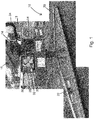
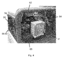
- Fig. 4 shows the arrangement of the inside of the body 12 showing the position of air filters 54, 56, air valves 58, 60 that are controlled by the PLC to open and close so as to apply and release vacuum to the vacuum pad 20; booster or emergency air valve 62 that allows fluid communication between the service and a reserve vacuum reservoirs in an emergency situation; junction box 67; a first hydraulic flow valve 64 that directs hydraulic flow to the hydraulic vacuum pump 34 and an emergency alarm 66 that alerts an operator to a low vacuum level.
- Fig. 5 shows the location of first and second hydraulic switches 68, 70 that convert the hydraulic signal to an electronic signal, a second hydraulic flow valve 72 that directs auxiliary hydraulic fluid to the rotator circuit that includes a rotator activation valve 74, a rotator direction valve 76 and a rotator speed valve 78.
- the vacuum lift attachment 10 is mounted to the stick of an excavator by means of the quick hitch coupling 16 and the auxiliary hydraulic lines 24 connected as per conventional hydraulic coupling to a hydraulic tool.
- the auxiliary hydraulic fluid When hydraulically attached, the auxiliary hydraulic fluid first enters a two stage or bidirectional flow reducer. The flow from the second stage always supplies the vacuum pump drive. The surplus from the second stage is directed to the rotator directional control valves.
- the vacuum pump has an output drive pulley that is used to drive an automotive type alternator.
- the alternator charges an on board battery that provides power to the PLC.
- the PLC remains dormant or in sleep mode until it is actuated in response to a hydraulic signal in the auxiliary hydraulic lines in response to actuation of the auxiliary hydraulic system by an operator using the excavator's auxiliary hydraulic actuator.
- the hydraulic signals are converted to electronic signals by means of electro hydraulic pressure switches.
- the operator turns the vacuum on by applying the auxiliary hydraulics.
- the green vacuum signal light 42 flashes showing that the vacuum is increasing.
- the green light 42 will show a solid colour.
- the PLC can be actuated to convert the mode of operation from vacuum mode to rotate mode. This is typically done by the operator giving two quick auxiliary hydraulic pulses (within one second). Rotate mode is indicated by amber light 50 turning on. Rotate mode is automatically cancelled by the PLC after four seconds of inaction.
- the hydraulic rotator 18 can then be operated according to conventional activation of the auxiliary hydraulic system actuator of the excavator.
- the vacuum pad 20 can be rotated, lifted and lowered over an object to be lifted.
- the vacuum pad 20 is lowered until the load sensor 36 is activated. Activation of the load sensor 36 shows that the vacuum pad 20 is in a vacuum seal position on the object or load. Further, the PLC is configured so that activation of the load switch automatically cancels rotate mode and reverts to vacuum mode.
- the operator can then apply a hydraulic signal to control the PLC to cause the air valve(s) that direct vacuum to the vacuum pad 20 to open, thereby applying a vacuum.
- the air valve(s) When the air valve(s) is opened and a vacuum is applied the blue vacuum applied light 44 will light up.
- the auxiliary hydraulics activates the vacuum pump 34 to build the vacuum in the system to the predetermined operating level. When this has been reached the green light 40 shows solid green.
- the auxiliary hydraulics lever can then be released; the operator should check the vacuum pad gauge 22 to ensure the vacuum level is stable prior to lifting the load.
- the PLC is configured to automatically allow rotate mode to be activated as desired by the operator.
- the PLC is also configured such that after the load sensor 36 has been deactivated signalling that the load has been lifted, it is not possible for an operator to release the vacuum so as to avoid inadvertently closing the air valve(s) causing dangerous releasing of the load.
- the vacuum lift attachment 10 and load are lowered to a ground surface until the load switch indicator light 46 illuminates.
- the auxiliary hydraulics are applied so as to release the vacuum from the vacuum pad 20 by causing the PLC to send an electronic signal to close the air valve so as to isolate the vacuum reservoir from the vacuum pad 20.
- the blue vacuum applied indicator light 46 will turn off. The operator should check that the vacuum pad gauge 22 reads zero before lifting away from the load.
- vacuum lift attachments as disclosed herein provide a number of advantages over current vacuum lift attachments. Further, the vacuum lift attachment can be controlled entirely from the work machine's existing hydraulic circuit, instead of a separate remote control or hard wired control. This makes operation much simpler. Further, the ability to use a quick hitch coupler has significant advantages in terms of productivity optimisation of machine time, costs and the like.
- Providing the rotator below the body means that the body does not rotate. This ensures that the signals 28 are always in the same place relative to the work station for easy view by an operator. Further, the auxiliary hydraulic lines are connected to the body in a fixed manner and there is no need to worry about the hydraulic connections being damaged during rotation (this is a common problem with hydraulic rotators).
- the vacuum pump has a "vacuum on demand” capability that can extend pump life, is quieter, and uses less fuel and less pollution.
Landscapes
- Engineering & Computer Science (AREA)
- Mechanical Engineering (AREA)
- Civil Engineering (AREA)
- Structural Engineering (AREA)
- General Engineering & Computer Science (AREA)
- Mining & Mineral Resources (AREA)
- Architecture (AREA)
- Life Sciences & Earth Sciences (AREA)
- Agronomy & Crop Science (AREA)
- Manipulator (AREA)
- Fluid-Pressure Circuits (AREA)
- Operation Control Of Excavators (AREA)
- Forklifts And Lifting Vehicles (AREA)
- Load-Engaging Elements For Cranes (AREA)
Abstract
Description
- The present disclosure relates to a vacuum lift attachment for a hydraulic work machine such as an excavator.
- The use of vacuum to lift objects is well known. Vacuum lift attachments for heavy machinery such as excavators are widely used for lifting heavy objects in the construction industry such as concrete, granite slabs, metal sheet and the like. Vacuum lift attachments are also used to lift pipes in pipeline construction. The vacuum lift attachments are fully self-contained with an on-board diesel engine with fuel tank to power an on-board vacuum pump with a vacuum pad or shoe. They are controlled either by a battery operated remote control or a hardwired control fitted inside an excavator or other work machine cabin.
- The vacuum lift attachments have a yoke for fitting to an end of an excavator stick. Generally the yokes are manufactured for fitting to a specific excavator size, although multi excavator yokes are available.
- Generally a hydraulic rotator is mounted between the yoke and the lift attachment for rotation of the attachment. The rotator is powered by an excavator's auxiliary hydraulic system.
- It is considered desirable in the construction, pipe-laying, and related industries to reduce costs and increase safety. To this end, there have been many developments and improvements in the vacuum attachment lifting industry with respect to improving on the existing yoke design, safety features, remote control features, shoe/pad design, engine/pump designs and the like.
- In the present specification and claims the term "comprising" shall be understood to have a broad meaning similar to the term "including" and will be understood to imply the inclusion of a stated integer or step or group of integers or steps but not the exclusion of any other integer or step or group of integers or steps. This definition also applies to variations on the term "comprising" such as "comprise" and "comprises".
- According to a first broad aspect there is disclosed a vacuum lift attachment for a hydraulic work machine, the hydraulic work machine including a control station, a lift arm to which the hydraulic work attachment can be coupled, an auxiliary hydraulic system for operating a coupled hydraulic work attachment and an hydraulic auxiliary actuator in the control station for that causes an auxiliary hydraulic control signal to generate upon actuation of the hydraulic auxiliary actuator by an operator; characterised in that the vacuum lift attachment comprises a body having an upper end that is adapted to be coupled to the lift arm of the hydraulic work machine and for hydraulic fluid connection to the auxiliary hydraulic system of the hydraulic work machine,
- a vacuum pad mounted to the lower end of the body,
- a hydraulic vacuum pump fluidly connected to the auxiliary hydraulic system,
- an electronic controller that is configured to receive an auxiliary hydraulic control signal and convert the auxiliary hydraulic control signal to an electronic signal for electronic control of the hydraulic vacuum pump by an operator using the auxiliary actuator in the control station.
- The present inventors have departed from the recognised conventions in the vacuum lifting arts and provided a vacuum lift attachment that does not require any remote or hardwired control, or self-contained diesel engine.
- The work machine may be any suitable work machine having an auxiliary hydraulic system for the operation of a hydraulically driven work attachment such as hydraulic hammers, rotators, augers, drills and the like.
- The work machine may be any suitable work machine that has, or can be adapted to have, an auxiliary hydraulic system, and includes excavators, backhoes, cranes and the like.
- The attachment has a body having an upper end that is adapted to be coupled to the end of the lift arm of the work machine.
- Suitably, the body has a pair of transverse mounting pins on the upper end that can be coupled to a quick hitch. The advantages of quick hitches to facilitate rapid exchange of work tools such as buckets on excavators and other heavy machinery is well known in the industry. Quick hitches allow work tools to be changed in a minute or less, with less man power and superior safety when compared with manually removing and loading connecting pins.
- It will be appreciated that by providing a quick hitch mounting option, an excavator or other suitable work machine can quickly and easily change a conventional work attachment such as a bucket with the disclosed vacuum lift attachments. This may be particularly desirable when laying pipe over a small pipe line length, as it allows a single machine to be used for excavating, pipe lifting, pipe laying and backfilling.
- The disclosed vacuum lift attachment may be provided with a hydraulic rotator to allow rotation of the vacuum pad so as to align the vacuum pad prior to loading and to align a loaded pipe prior to unloading.
- The use of hydraulic rotators with vacuum lift attachments is well known in the industry. The hydraulic rotators are operatively mounted to the lifting arm of the work machine where they can be connected to the auxiliary hydraulic lines.
- Suitably the disclosed vacuum lift attachments have the rotator mounted between the body and the vacuum pad. This means that only the vacuum pad rotates instead of the whole vacuum lift attachment. This has advantages in that there is less overall weight for the rotator to operate, particularly when rotating the vacuum shoe in the unloaded state.
- Thus there is also disclosed a vacuum lift attachment that further comprises a hydraulic rotator mounted to the lower end of the body and between the body and the vacuum pad.
- It will be appreciated that such an arrangement has applications to vacuum lift attachments other than those disclosed herein.
- The disclosed vacuum lift attachments have a vacuum pad. The vacuum pad may be any suitable vacuum pad depending upon the material to be lifted. Matching vacuum pads with materials to be lifted is known in the art.
- The disclosed vacuum lift attachments include a hydraulic pump that is fluidly connected to the auxiliary hydraulic system so that the pump may be driven thereby. The vacuum pump will only operate when there is a flow of auxiliary hydraulic fluid. This provides the pump with a "vacuum on demand function". This may be compared to conventional diesel driven vacuum lift attachments in which the diesel engine is running continuously, even when vacuum is not required. This increases noise and pollution levels and is expensive to operate. Further, only operating the vacuum pump when desired can extend the service life on the vacuum pump.
- The vacuum lift attachment suitably has a vacuum reservoir in fluid communication with the vacuum pad, which fluid flow is controlled by an air valve(s) operable between open and closed positons so as to apply and close supply of vacuum to the pads.
- Suitably, the vacuum reservoir includes a first service reservoir and a second reserve reservoir. The reservoirs may be discrete units or may be a single unit divided into two parts. If in use, an emergency situation arises if there is a loss of vacuum when carrying a load in the event of a vacuum leak, the electronic controller (discussed below) is configured to sense the loss of vacuum and to automatically operatively connect the reserve reservoir to the vacuum pad so as to avoid or at least partially avoid further vacuum loss. This will give an operator sufficient time to safely lower and disengage the load. Suitably the reserve reservoir may be connected to the main reservoir.
- Also disclosed is a vacuum work attachment that further comprises at least one vacuum reservoir in fluid communication with the vacuum pad, in which the fluid communication is controlled by at least one air valve operable between an open position in which a vacuum is applied to the vacuum pad and a closed positon in which no or reduced vacuum is applied to the vacuum pad.
- Suitably, the vacuum lift attachment includes a first service reservoir and a second reserve reservoir and the second reserve vacuum reservoir is fluidly isolated from the vacuum pad when the vacuum pad is carrying a load at or above a predetermined safe vacuum level, and if the vacuum level falls below the predetermined safe vacuum level a second air valve is actuated to fluidly connect the reserve vacuum reservoir to the vacuum pad.
- The vacuum lift attachment also includes an electronic controller that is configured to receive control input through the auxiliary hydraulic system in response to actuation of the auxiliary actuator such that operation of the vacuum lift attachment can be controlled using the auxiliary actuator in the control station.
- The hydraulic signals from the auxiliary hydraulic system are suitably converted to electric signals by electro-hydraulic pressure switches. Such switches open or close electrical contacts when a set pressure is achieved or exceeded.
- Suitably the electronic controller is a programmable logic controller (PLC).
- Suitably, the electronic controller is configured to remain in a sleep mode until a hydraulic signal is detected by the controller and the controller is activated to an operative mode.
- When the auxiliary hydraulic system is activated, the vacuum pump builds up a vacuum until it reaches the desired or predetermined level.
- Suitably the vacuum lift attachment includes a sensor that is receptive to the vacuum detected by a vacuum gauge that produces an audio and/or visual signal that can be seen and/or heard by an operator in the control station of the work machine to indicate when the vacuum has reached the desired level.
- Suitably an audio and/or visual signal is produced when the vacuum is being applied.
- Thus, there is disclosed a vacuum lift attachment that further includes a vacuum sensor operatively connected to a vacuum gauge that is configured to produce an audio and/or visual signal that can be seen and/or heard by an operator in the control station of the work machine to indicate when the vacuum has reached the predetermined operating level.
- In use, when the desired vacuum has been reached, an operator can place the vacuum pad in contact with an object to be lifted. Suitably the vacuum lift attachment includes a load sensor that senses when the vacuum pad has contacted the load. Suitably the sensor causes an audio and/or visual signal that can be seen and/or heard by the operator in the control station. In this case, after the signal is seen and/or heard, the operator can then proceed to apply vacuum to the object.
- Suitably a further audio and/or visual signal is generated so as to confirm to the operator that vacuum is being applied. A further signal is suitably produced when there is sufficient vacuum applied to lift the object. When the object is lifted, the load sensor, if present, is deactivated such that the electronic controller knows that a load has been lifted. Suitably, the electronic controller will prevent any inadvertent activation by an operator that may release the vacuum whilst a load is being lifted.
- Thus, there is disclosed a vacuum lift attachment that further includes a load sensor that is activated when the vacuum pad has contacted a load to be lifted and when activated, an audio and/or visual signal that can be seen and/or heard by the operator in the control station.
- The electronic controller is configured to automatically disengage rotate mode when the load sensor is activated.
- Suitably, when the vacuum is being applied to the load to be lifted, an audio and/or visual signal is generated so as to confirm to the operator that vacuum is being applied and a further signal is generated when there is sufficient vacuum applied to lift the object.
- Suitably that when the load is lifted, the load sensor is deactivated and the electronic controller is configured to receive a signal that the load sensor is deactivated and prevents inadvertent operator release of the applied vacuum.
- The vacuum lift attachment suitably includes a bidirectional valve system for splitting the auxiliary hydraulic fluid flow into a first stream that drives and controls the vacuum pump and a second stream for operation of the hydraulic rotator. In this case, the controller is suitably configured to operate either in a vacuum control mode that responds to auxiliary hydraulic signals from the auxiliary actuator or a rotate mode that responds to auxiliary hydraulic signals from the auxiliary actuator. In this way an operator can control both functions using the work machines existing auxiliary hydraulic controls.
- Thus there is disclosed a vacuum work attachment that when the electronic controller is on the operative mode, rather than a sleep mode, the electronic controller is further configured to operate the vacuum work attachment either in a vacuum control mode or a rotate mode.
- Suitably, in the rotate mode, a portion of the auxiliary hydraulic fluid is bled off and is used to allow the vacuum pump to continue running.
- Suitably the controller selects rotate mode upon receipt of a suitable hydraulic signal. For example, the controller may be responsive to a predetermined sequence of hydraulic pulses to activate rotation mode. The rotator may then be operated as per conventional auxiliary hydraulic control.
- In some embodiments, the hydraulic rotator has a two speed control valve function so that it can supply a greater flow of hydraulic fluid when the vacuum lift attachment is loaded when compared to the unloaded state.
- It is desirable to be able to rotate an unloaded lift vacuum pad for the purposes of correct alignment with an object to be lifted and to correctly place a lifted object. Accordingly, rotate mode may be deactivated or deselected when a load is being engaged or disengaged. In this way, when rotate mode is disengaged, the signals received by the electronic controller are understood by the electronic controller to be actuation signals for vacuum control.
- In the embodiment where the vacuum lift attachment includes a load sensor, suitably the electronic controller is configured to automatically disengage rotate mode when the load sensor is actuated.
- Suitably, the electronic controller is battery powered. In this case, the vacuum lift attachment suitably includes an alternator that is driven by drive pulley operatively attached to the vacuum pump for charging the battery.
- According to a further broad form of the disclosure, there is provided an electronic controller for controlling a vacuum lift attachment that is adapted to be coupled to a lifting arm of a hydraulic work machine for hydraulic fluid connection to an auxiliary hydraulic system of the work machine, the vacuum lift attachment including an hydraulic pump, at least one vacuum reservoir and a vacuum show and a sensor system;
- the electronic controller being configured to receive hydraulic signals from the auxiliary hydraulic circuit and convert the hydraulic signal to electronic signals so as to electronically control at least one of the following actions, opening of an air valve so as to allow fluid communication between the vacuum reservoir and the vacuum pad, closing of an air valve so as to close any fluid communication between the vacuum pad and the at least one vacuum reservoir and the sensor system that includes at least one sensor for sensing when the vacuum has reached a predetermined operating level and a sensor for sensing when the vacuum level has fallen below a predetermined safety level.
- In the embodiment in which the vacuum lift attachment includes a rotator, the electronic control is suitably configured to electronically control a flow of hydraulic fluid to the rotator so as to control the supply of hydraulic fluid to the rotator to activate the rotator and to control the rotation and speed thereof.
- According to a further aspect, there is disclosed a vacuum lift attachment for a hydraulic work machine having a control station, a lift arm to which a hydraulic work attachment can be coupled; the vacuum lift attachment comprising:
- a body having an upper end having connecting a pair of connecting pins for coupling to a quick hitch on the lifting arm of the hydraulic work machine;
- a hydraulic rotator mounted to the lower end of the body; and
- a vacuum pad mounted to the hydraulic rotator for rotation relative to the body that is operable between a suction position and a release position.
- According to a further broad aspect there is disclosed a vacuum lift attachment for lifting a load for a hydraulic work machine having, a lift arm to which the vacuum lift attachment can be coupled,
the vacuum lift attachment comprising: - a body having an upper end that is adapted to be coupled to the lift arm of the hydraulic work machine;
- a vacuum pad mounted to the lower end of the body;
- a vacuum pump in fluid communication with a first service vacuum reservoir, an air valve operable between an open position in which the first service reservoir is in fluid communication with the vacuum pad so as to apply a vacuum thereto and a closed position; and
- a second reserve vacuum reservoir that is fluidly isolated from the vacuum pad when the vacuum pad is carrying a load at or above a predetermined vacuum level, and if the vacuum level falls below the predetermined level a second air valve is actuated to fluidly connect the reserve vacuum reservoir to the vacuum pad.
-
- Fig. 1
- is a perspective view of a vacuum lift apparatus according to one aspect of the present disclosure;
- Fig. 2
- is a schematic view of the vacuum lift attachment;
- Fig. 3
- is a detail of the signal box of the vacuum lift attachment;
- Fig. 4
- is a view of part of the internal section of the body of the vacuum lift attachment; and
- Fig. 5
- shows another view of part of the internal section of the body of the vacuum lift attachment.
-
Fig. 1 shows avacuum lift attachment 10 as disclosed herein. The vacuum lift attachment includes abody 12 having anupper end 13 and alower end 17, connectingpins 14 on theupper end 13 of thebody 12 for connection to aquick hitch 16. Arotator 18 is located on the bottom end of thebody 12. - A
vacuum pad 20 is mounted to therotator 18. A vacuumpad pressure gauge 22 is located on thevacuum pad 20. - The vacuum lift attachment is hydraulically connected to the work machine through the auxiliary hydraulic fluid lines 24.
- An electronic controller that is a
PLC 26 is mounted on one side of thebody 12.Signals 28 in the form of different coloured LED lights are located on the front of the PLC. Thesignals 28 are configured to be easily visible to an operator siting in the control station of an excavator. Thesignals 28 will be described in further detail below. Next to thesignals 28 is a hydraulicfluid level indicator 30 and a vacuum gauge 32 showing the vacuum level in the service air tank or vacuum reservoir. - A
hydraulic vacuum pump 34 is located on the other side of thebody 12. -
Fig. 2 is a schematic side view of thevacuum lift attachment 10. A load switch orsensor 36 is located at theupper end 13 of thebody 12 and is mounted on atelescopic arm 38. In use, when thevacuum pad 20 is placed upon an object or load to be lifted, thereby applying a load to thevacuum pad 20, thetelescopic arm 38 moves upward so as to activate theload sensor 36. When thevacuum pad 20 is lifted off the ground, either loaded or unloaded, theload sensor 36 will automatically deactivate. -
Fig. 3 shows thesignals 28 in detail. The signals include agreen light 40. The PLC is configured to receive signals from a service tank vacuum sensor and cause the green vacuum light 40 to flash as the vacuum is increasing and to show a solid green light when the vacuum has reached the predetermined operating vacuum level. - A second
red warning light 42 is located belowgreen light 40. The PLC is configured to activate the red light when the vacuum level drops to a predetermined dangerous level. - This signals to an operator to abort a lift immediately and lower a load safely to the ground.
- A vacuum applied
signal light 44 between the red 40 and 42 green lights will show blue when a vacuum is being applied. - The PLC is further configured to turn the light 46 on the upper right corner of the
signals 28 to show amber when theload sensor 36 is activated, to turn the light 48 on the lower right corner to show amber when the auxiliary hydraulic fluid is being applied, to turn the light 50 on the lower left corner to show amber when thevacuum lift attachment 10 is in rotate mode (described below) and analternator warning light 52 in the upper left corner. -
Fig. 4 shows the arrangement of the inside of thebody 12 showing the position ofair filters vacuum pad 20; booster oremergency air valve 62 that allows fluid communication between the service and a reserve vacuum reservoirs in an emergency situation;junction box 67; a firsthydraulic flow valve 64 that directs hydraulic flow to thehydraulic vacuum pump 34 and anemergency alarm 66 that alerts an operator to a low vacuum level. -
Fig. 5 shows the location of first and second hydraulic switches 68, 70 that convert the hydraulic signal to an electronic signal, a secondhydraulic flow valve 72 that directs auxiliary hydraulic fluid to the rotator circuit that includes arotator activation valve 74, arotator direction valve 76 and arotator speed valve 78. - The operation of the
vacuum lift attachment 10 will now be described. Thevacuum lift attachment 10 is mounted to the stick of an excavator by means of thequick hitch coupling 16 and the auxiliaryhydraulic lines 24 connected as per conventional hydraulic coupling to a hydraulic tool. - When hydraulically attached, the auxiliary hydraulic fluid first enters a two stage or bidirectional flow reducer. The flow from the second stage always supplies the vacuum pump drive. The surplus from the second stage is directed to the rotator directional control valves.
- The vacuum pump has an output drive pulley that is used to drive an automotive type alternator. The alternator charges an on board battery that provides power to the PLC.
- The PLC remains dormant or in sleep mode until it is actuated in response to a hydraulic signal in the auxiliary hydraulic lines in response to actuation of the auxiliary hydraulic system by an operator using the excavator's auxiliary hydraulic actuator. The hydraulic signals are converted to electronic signals by means of electro hydraulic pressure switches.
- The operator turns the vacuum on by applying the auxiliary hydraulics. The green vacuum signal light 42 flashes showing that the vacuum is increasing. When the vacuum has reached the predetermined operating level, the green light 42will show a solid colour. When the auxiliary hydraulic system is being used to operate the vacuum pump it is known as vacuum mode.
- When the vacuum has built up, the PLC can be actuated to convert the mode of operation from vacuum mode to rotate mode. This is typically done by the operator giving two quick auxiliary hydraulic pulses (within one second). Rotate mode is indicated by
amber light 50 turning on. Rotate mode is automatically cancelled by the PLC after four seconds of inaction. - The
hydraulic rotator 18 can then be operated according to conventional activation of the auxiliary hydraulic system actuator of the excavator. Thevacuum pad 20 can be rotated, lifted and lowered over an object to be lifted. - The
vacuum pad 20 is lowered until theload sensor 36 is activated. Activation of theload sensor 36 shows that thevacuum pad 20 is in a vacuum seal position on the object or load. Further, the PLC is configured so that activation of the load switch automatically cancels rotate mode and reverts to vacuum mode. - The operator can then apply a hydraulic signal to control the PLC to cause the air valve(s) that direct vacuum to the
vacuum pad 20 to open, thereby applying a vacuum. When the air valve(s) is opened and a vacuum is applied the blue vacuum applied light 44 will light up. The auxiliary hydraulics activates thevacuum pump 34 to build the vacuum in the system to the predetermined operating level. When this has been reached thegreen light 40 shows solid green. The auxiliary hydraulics lever can then be released; the operator should check thevacuum pad gauge 22 to ensure the vacuum level is stable prior to lifting the load. - When the load is lifted the
load sensor 36 will be deactivated. The PLC is configured to automatically allow rotate mode to be activated as desired by the operator. The PLC is also configured such that after theload sensor 36 has been deactivated signalling that the load has been lifted, it is not possible for an operator to release the vacuum so as to avoid inadvertently closing the air valve(s) causing dangerous releasing of the load. - In order to release the load, the
vacuum lift attachment 10 and load are lowered to a ground surface until the loadswitch indicator light 46 illuminates. The auxiliary hydraulics are applied so as to release the vacuum from thevacuum pad 20 by causing the PLC to send an electronic signal to close the air valve so as to isolate the vacuum reservoir from thevacuum pad 20. When the air valve(s) close, the blue vacuum applied indicator light 46 will turn off. The operator should check that thevacuum pad gauge 22 reads zero before lifting away from the load. - After the
vacuum lift attachment 10 has unloaded, it will automatically shut down after about 2 minutes of inaction. - It will be appreciated that the vacuum lift attachments as disclosed herein provide a number of advantages over current vacuum lift attachments. Further, the vacuum lift attachment can be controlled entirely from the work machine's existing hydraulic circuit, instead of a separate remote control or hard wired control. This makes operation much simpler. Further, the ability to use a quick hitch coupler has significant advantages in terms of productivity optimisation of machine time, costs and the like.
- Providing the rotator below the body means that the body does not rotate. This ensures that the
signals 28 are always in the same place relative to the work station for easy view by an operator. Further, the auxiliary hydraulic lines are connected to the body in a fixed manner and there is no need to worry about the hydraulic connections being damaged during rotation (this is a common problem with hydraulic rotators). - The vacuum pump has a "vacuum on demand" capability that can extend pump life, is quieter, and uses less fuel and less pollution.
- It will be appreciated that various changes and modifications may be made to the present invention as disclosed and claimed herein without departing from the spirt and scope thereof.
Claims (15)
- A vacuum lift attachment (10) for a hydraulic work machine, the hydraulic work machine including a control station, a lift arm to which the hydraulic work attachment can be coupled, an auxiliary hydraulic system for operating a coupled hydraulic work attachment and an auxiliary hydraulic actuator in the control station that upon actuation by an operator causes an auxiliary hydraulic control signal to generate; characterized in that the vacuum lift attachment comprises:a body (12) having an upper end (13) that is adapted to be coupled to the lift arm of the hydraulic work machine and for hydraulic fluid connection to the auxiliary hydraulic system of the hydraulic work machine;a vacuum pad (20) mounted to the lower end of the body (10);a hydraulic vacuum pump (34) fluidly connected to the auxiliary hydraulic system; andan electronic controller (26) that is configured to receive an auxiliary hydraulic control signal and convert the auxiliary hydraulic control signal to an electronic signal for electronic control of the hydraulic vacuum pump by an operator actuating the auxiliary hydraulic actuator in the control station.
- The vacuum lift attachment (10) of claim 1, characterized in that the vacuum lift attachment (10) further comprises a hydraulic rotator (18) mounted to the lower end (17) of the body (10) and between the body (10) and the vacuum pad (20).
- The vacuum lift attachment (10) of claim 2, characterized in that the vacuum lift attachment (10) includes a bidirectional valve system (64, 72) for splitting the auxiliary hydraulic fluid flow into a first stream that drives and controls the hydraulic vacuum pump (34) and a second stream for operation of the hydraulic rotator (18).
- The vacuum lift attachment (10) of claim 2 or claim 3, characterized in that the hydraulic rotator (18) has a two speed control valve function so that it can supply a greater flow of hydraulic fluid when the vacuum lift attachment is loaded when compared to the unloaded state.
- The vacuum lift attachment (10) of any one of claims 1 to 4, characterised in that the vacuum lift attachment comprises a vacuum reservoir in fluid communication with the vacuum pad (20), in which the fluid communication is controlled by at least one air valve (58, 60) operable between an open and a closed positons so as to apply and close a supply of vacuum to the vacuum pad (20).
- The vacuum lift attachment (10) of claim 5, wherein the vacuum reservoir includes a first service reservoir and a second reserve reservoir and the second reserve vacuum reservoir is fluidly isolated from the vacuum pad (20) when the vacuum pad (20) is carrying a load at or above a predetermined safe vacuum level, and if the vacuum level falls below the predetermined safe vacuum level a second air valve is actuated to fluidly connect the reserve vacuum reservoir to the vacuum pad.
- The vacuum lift attachment (10) of any one of claims 1 to 6, characterised in that the electronic controller (26) is a programmable logic controller (PLC) that is configured to remain in a sleep mode until an auxiliary hydraulic control signal is detected by the electronic controller and the electronic controller is activated to an operative mode.
- The vacuum lift attachment (10) of claim 6, characterized in that when the electronic controller (26) is on the operative mode the electronic controller (26) is further configured to operate the vacuum work attachment (10) either in a vacuum control mode or a rotate mode.
- The vacuum lift attachment (10) of claim 8, characterized in that when the auxiliary hydraulic actuator is activated by an operator, the hydraulic vacuum pump (34) builds up a vacuum until it reaches a predetermined operating level.
- The vacuum lift attachment (10) of claim 8, characterized in that the vacuum lift attachment (10) further includes a vacuum sensor operatively connected to a vacuum gauge (22) that is configured to produce an audio and/or visual signal that can be seen and/or heard by an operator in the control station of the work machine to indicate when the vacuum has reached the predetermined operating level.
- The vacuum lift attachment (10) of any one of claims 8 to 10, characterized in that the vacuum lift attachment (10) further includes a load sensor (36) that is activated when the vacuum pad has contacted a load to be lifted and causes activation of an audio and/or visual signal that can be seen and/or heard by the operator in the control station.
- The vacuum lift attachment (10) of claim 11, characterized in that the electronic controller (26) is configured to automatically disengage rotate mode when the load sensor is activated.
- The vacuum lift attachment (10) of claim 11 or claim 12, characterized in that when the vacuum is being applied to the load to be lifted, an audio and/or visual signal (40) is generated so as to confirm to the operator that vacuum is being applied and a further signal is generated when there is sufficient vacuum applied to lift the load.
- The vacuum lift attachment (10) of claim 13, characterized in that when the load is lifted, the load sensor (36) is deactivated and the electronic controller (26) is configured to receive a signal that the load sensor (36) is deactivated and prevents inadvertent operator release of the applied vacuum.
- The vacuum lift attachment (10) of any one of claims 1 to 14, wherein, the electronic controller (26) is battery powered and the vacuum lift attachment (10) includes an alternator that is driven by a drive pulley operatively attached to the vacuum pump (34) for charging the battery.
Applications Claiming Priority (1)
| Application Number | Priority Date | Filing Date | Title |
|---|---|---|---|
| AU2015903451A AU2015903451A0 (en) | 2015-08-26 | A vacuum lift attachment |
Publications (3)
| Publication Number | Publication Date |
|---|---|
| EP3135622A2 true EP3135622A2 (en) | 2017-03-01 |
| EP3135622A3 EP3135622A3 (en) | 2017-06-21 |
| EP3135622B1 EP3135622B1 (en) | 2022-12-07 |
Family
ID=56801425
Family Applications (1)
| Application Number | Title | Priority Date | Filing Date |
|---|---|---|---|
| EP16185639.8A Active EP3135622B1 (en) | 2015-08-26 | 2016-08-25 | Vacuum lift attachment |
Country Status (3)
| Country | Link |
|---|---|
| US (1) | US10071885B2 (en) |
| EP (1) | EP3135622B1 (en) |
| AU (1) | AU2016219668B2 (en) |
Families Citing this family (8)
| Publication number | Priority date | Publication date | Assignee | Title |
|---|---|---|---|---|
| US10888976B2 (en) * | 2017-12-22 | 2021-01-12 | Biesse S.P.A. | Suction cup unit for gripping workpieces |
| CA3103522C (en) | 2018-07-16 | 2023-11-21 | Gilead Sciences, Inc. | Capsid inhibitors for the treatment of hiv |
| AU2020370376B2 (en) * | 2019-10-24 | 2025-12-11 | Vacuworx Global, LLC | A portable vacuum lifter system |
| US11963331B2 (en) * | 2021-06-28 | 2024-04-16 | Baidu Usa Llc | Fully redundant cooling unit with phase change flow control unit |
| AU2022403012B2 (en) | 2021-12-03 | 2026-02-12 | Gilead Sciences, Inc. | Therapeutic compounds for hiv virus infection |
| AU2022399845B2 (en) | 2021-12-03 | 2026-03-26 | Gilead Sciences, Inc. | Therapeutic compounds for hiv virus infection |
| FI4440702T3 (en) | 2021-12-03 | 2025-08-08 | Gilead Sciences Inc | THERAPEUTIC COMPOUNDS FOR HIV VIRUS INFECTION |
| EP4727878A1 (en) * | 2023-06-19 | 2026-04-22 | Austrack Equipment Pty Ltd | Vacuum lifting device and system |
Family Cites Families (32)
| Publication number | Priority date | Publication date | Assignee | Title |
|---|---|---|---|---|
| BE494127A (en) | 1950-02-01 | |||
| US3351370A (en) | 1965-07-19 | 1967-11-07 | Hyster Co | Vacuum barrel handlers |
| GB1165382A (en) | 1966-08-08 | 1969-09-24 | Pilkington Brothers Ltd | Improvements in or relating to Vacuum Holding Apparatus |
| US4641007A (en) | 1981-10-05 | 1987-02-03 | Horst Lach | Process and device for treatment of metal-bonded nonconductive materials |
| NO161311C (en) | 1983-02-24 | 1989-08-02 | Reinhard Goepfert | Self-propelled device for lifting and moving elements to be lifted. |
| EP0176496B1 (en) | 1984-09-25 | 1987-12-09 | DIAMANT BOART Société Anonyme | Apparatus for handling glass sheets |
| US4750768A (en) * | 1986-05-14 | 1988-06-14 | Kumar V Sam | Gripper device |
| JPH0795070B2 (en) * | 1986-06-10 | 1995-10-11 | 東ソー株式会社 | Adsorption heads for transporting reaction cups used in biochemical reaction measuring devices |
| DE3735864C1 (en) | 1987-10-23 | 1989-02-16 | Reinhard Dipl-Ing Goepfert | Suction lifter for concrete blocks |
| HU215333B (en) * | 1990-05-22 | 1998-12-28 | Glasstech Inc. | Apparatus and method for vacuum forming of heated glass panes |
| US5297830A (en) * | 1993-04-05 | 1994-03-29 | Hoke Thomas A | Automatic load sensing vacuum valve |
| US5752729A (en) | 1993-11-04 | 1998-05-19 | Comalco Aluminium Limited | Vacuum lifting device |
| JP2933488B2 (en) * | 1994-08-10 | 1999-08-16 | 日本電気株式会社 | Polishing method and polishing apparatus |
| DE29704848U1 (en) | 1996-04-17 | 1997-04-30 | Laursen, Allan, Lemvig | Vacuum transport device for attachment to the boom device of a construction machine |
| US6279225B1 (en) * | 1996-06-05 | 2001-08-28 | Schlumberger Technologies, Inc. | Apparatus for handling packaged IC's |
| US7400058B1 (en) | 2001-03-21 | 2008-07-15 | Douglas Dynamics, L.L.C. | Vehicle mounted accessory with multiplexing |
| US6767177B2 (en) | 2002-04-15 | 2004-07-27 | Kary A. Opitz | Magnetic lifting system |
| US6691435B1 (en) * | 2002-09-25 | 2004-02-17 | Sno-Way International, Inc. | Plow system including a hydraulic fluid diverter |
| US7721825B2 (en) * | 2007-01-18 | 2010-05-25 | Diamond Products, Limited | Portable concrete boring machine |
| FR2932240B1 (en) | 2008-06-10 | 2013-03-15 | Dle Specialites | METHOD FOR POSITIONING AND SLEEPING PIPES OF PIPE PIPES (PIPES) AT THE TOP OF TRENCHES AS WELL AS A DEVICE HAVING MANIPULATION VENTS FOR IMPLEMENTING SAID METHOD |
| DE202008015603U1 (en) | 2008-11-25 | 2009-02-26 | Winden- Und Maschinenbau Gressbach Gmbh | Laying device for pipes |
| US8375711B2 (en) | 2009-01-19 | 2013-02-19 | Vaculift, Inc. | Compact vacuum material handler |
| AU2010202108A1 (en) | 2009-03-06 | 2010-09-23 | Gerard O'brien | A work machine for lifting heavy objects |
| AU2011250782B2 (en) | 2010-11-15 | 2017-03-23 | Matthew Dridan | Vacuum work attachment |
| US8528955B2 (en) * | 2011-01-24 | 2013-09-10 | AMF automation Technologies, LLC | Robot end effector with cable management |
| AU2012201885A1 (en) | 2011-04-01 | 2012-10-18 | Matthew Graeme Dridan | A pipe lift attachment |
| EP2892838B1 (en) | 2012-08-24 | 2016-12-14 | Vacuworx Global, LLC | Traffic barrier lifter |
| KR20140082373A (en) | 2012-12-24 | 2014-07-02 | (주)티앤에치코퍼레이션 | hydraulic type scrap magnet device |
| DE102013003209A1 (en) | 2013-02-26 | 2014-08-28 | Reinhard Göpfert | Vacuum lifting tool for handling pipeline tubes in large excavators, has vacuum pump-blower with flanged hydraulic motor which is supplied through exposed oil circuit of supporting device over continuously adjustable divider with oil flow |
| DE202013001823U1 (en) | 2013-02-26 | 2013-03-26 | Reinhard Göpfert | Vacuum lifting tool without gasoline, diesel or electric motor |
| US9896892B2 (en) * | 2014-04-11 | 2018-02-20 | Vacuworx Global, LLC | System and method for handling drill pipe using a vacuum handler |
| ES2845927T3 (en) * | 2014-06-26 | 2021-07-28 | Schmalz J Gmbh | Installation for handling workpieces |
-
2016
- 2016-08-25 US US15/247,380 patent/US10071885B2/en active Active
- 2016-08-25 AU AU2016219668A patent/AU2016219668B2/en active Active
- 2016-08-25 EP EP16185639.8A patent/EP3135622B1/en active Active
Non-Patent Citations (1)
| Title |
|---|
| None |
Also Published As
| Publication number | Publication date |
|---|---|
| EP3135622A3 (en) | 2017-06-21 |
| EP3135622B1 (en) | 2022-12-07 |
| AU2016219668B2 (en) | 2021-10-21 |
| US10071885B2 (en) | 2018-09-11 |
| US20170057794A1 (en) | 2017-03-02 |
| AU2016219668A1 (en) | 2017-03-16 |
Similar Documents
| Publication | Publication Date | Title |
|---|---|---|
| US10071885B2 (en) | Vacuum lift attachment | |
| US9285023B2 (en) | Hydraulic drive of operating machine | |
| CN103459727B (en) | For storing the equipment filling accumulator | |
| EP0866027A3 (en) | Hydraulic control apparatus for industrial vehicles | |
| US9650759B2 (en) | Control apparatus for hydraulic heavy machinery | |
| US10114404B2 (en) | Hydraulic control system | |
| US10837473B2 (en) | Hydraulic system | |
| WO2008085247A1 (en) | Freely rotatable closed grapple head and machine using same | |
| CN114934559A (en) | Quick-change device disengagement control system and method and engineering machinery | |
| JPH0685449U (en) | Exhaust plate control device | |
| CN2652902Y (en) | Hydraulic crane control system | |
| EP2221271B1 (en) | Work platform | |
| CN222770513U (en) | A hydraulic control system and material grabber capable of preventing bottoming damage | |
| CN108394822A (en) | A kind of elevator robot control system(RCS) | |
| KR20050039716A (en) | Machine tool and method for operating a machine tool | |
| US6122848A (en) | Hydraulic drive type working vehicle | |
| CN207957598U (en) | A kind of elevator robot control system(RCS) | |
| KR20090069687A (en) | Excavator Boom Lower Safety System | |
| EP3743563B1 (en) | Excavator including upper swing body having free swing function | |
| SE1850933A1 (en) | Hydraulic system and method for controlling the speed and pressure of a hydraulic cylinder | |
| US12280990B2 (en) | Winch drive device in crane | |
| SE539072C2 (en) | System of attachment brackets to check its locking position | |
| EP3778298B1 (en) | A cabin control valve integrated with solenoid direction control valve | |
| CN211279076U (en) | Auger descending protection device and sand mixing truck | |
| US20110095249A1 (en) | Hydraulic crane system for lifting a crane on a vehicle |
Legal Events
| Date | Code | Title | Description |
|---|---|---|---|
| PUAI | Public reference made under article 153(3) epc to a published international application that has entered the european phase |
Free format text: ORIGINAL CODE: 0009012 |
|
| STAA | Information on the status of an ep patent application or granted ep patent |
Free format text: STATUS: THE APPLICATION HAS BEEN PUBLISHED |
|
| AK | Designated contracting states |
Kind code of ref document: A2 Designated state(s): AL AT BE BG CH CY CZ DE DK EE ES FI FR GB GR HR HU IE IS IT LI LT LU LV MC MK MT NL NO PL PT RO RS SE SI SK SM TR |
|
| AX | Request for extension of the european patent |
Extension state: BA ME |
|
| PUAL | Search report despatched |
Free format text: ORIGINAL CODE: 0009013 |
|
| AK | Designated contracting states |
Kind code of ref document: A3 Designated state(s): AL AT BE BG CH CY CZ DE DK EE ES FI FR GB GR HR HU IE IS IT LI LT LU LV MC MK MT NL NO PL PT RO RS SE SI SK SM TR |
|
| AX | Request for extension of the european patent |
Extension state: BA ME |
|
| RIC1 | Information provided on ipc code assigned before grant |
Ipc: E02F 3/96 20060101ALI20170517BHEP Ipc: E02F 3/36 20060101ALI20170517BHEP Ipc: B66C 1/02 20060101AFI20170517BHEP |
|
| STAA | Information on the status of an ep patent application or granted ep patent |
Free format text: STATUS: REQUEST FOR EXAMINATION WAS MADE |
|
| 17P | Request for examination filed |
Effective date: 20171212 |
|
| RBV | Designated contracting states (corrected) |
Designated state(s): AL AT BE BG CH CY CZ DE DK EE ES FI FR GB GR HR HU IE IS IT LI LT LU LV MC MK MT NL NO PL PT RO RS SE SI SK SM TR |
|
| STAA | Information on the status of an ep patent application or granted ep patent |
Free format text: STATUS: EXAMINATION IS IN PROGRESS |
|
| 17Q | First examination report despatched |
Effective date: 20210420 |
|
| GRAP | Despatch of communication of intention to grant a patent |
Free format text: ORIGINAL CODE: EPIDOSNIGR1 |
|
| STAA | Information on the status of an ep patent application or granted ep patent |
Free format text: STATUS: GRANT OF PATENT IS INTENDED |
|
| INTG | Intention to grant announced |
Effective date: 20220622 |
|
| GRAS | Grant fee paid |
Free format text: ORIGINAL CODE: EPIDOSNIGR3 |
|
| GRAA | (expected) grant |
Free format text: ORIGINAL CODE: 0009210 |
|
| STAA | Information on the status of an ep patent application or granted ep patent |
Free format text: STATUS: THE PATENT HAS BEEN GRANTED |
|
| AK | Designated contracting states |
Kind code of ref document: B1 Designated state(s): AL AT BE BG CH CY CZ DE DK EE ES FI FR GB GR HR HU IE IS IT LI LT LU LV MC MK MT NL NO PL PT RO RS SE SI SK SM TR |
|
| REG | Reference to a national code |
Ref country code: GB Ref legal event code: FG4D |
|
| REG | Reference to a national code |
Ref country code: CH Ref legal event code: EP Ref country code: AT Ref legal event code: REF Ref document number: 1536212 Country of ref document: AT Kind code of ref document: T Effective date: 20221215 |
|
| REG | Reference to a national code |
Ref country code: DE Ref legal event code: R096 Ref document number: 602016076742 Country of ref document: DE |
|
| REG | Reference to a national code |
Ref country code: IE Ref legal event code: FG4D |
|
| REG | Reference to a national code |
Ref country code: LT Ref legal event code: MG9D |
|
| REG | Reference to a national code |
Ref country code: NL Ref legal event code: MP Effective date: 20221207 |
|
| PG25 | Lapsed in a contracting state [announced via postgrant information from national office to epo] |
Ref country code: SE Free format text: LAPSE BECAUSE OF FAILURE TO SUBMIT A TRANSLATION OF THE DESCRIPTION OR TO PAY THE FEE WITHIN THE PRESCRIBED TIME-LIMIT Effective date: 20221207 Ref country code: NO Free format text: LAPSE BECAUSE OF FAILURE TO SUBMIT A TRANSLATION OF THE DESCRIPTION OR TO PAY THE FEE WITHIN THE PRESCRIBED TIME-LIMIT Effective date: 20230307 Ref country code: LT Free format text: LAPSE BECAUSE OF FAILURE TO SUBMIT A TRANSLATION OF THE DESCRIPTION OR TO PAY THE FEE WITHIN THE PRESCRIBED TIME-LIMIT Effective date: 20221207 Ref country code: FI Free format text: LAPSE BECAUSE OF FAILURE TO SUBMIT A TRANSLATION OF THE DESCRIPTION OR TO PAY THE FEE WITHIN THE PRESCRIBED TIME-LIMIT Effective date: 20221207 Ref country code: ES Free format text: LAPSE BECAUSE OF FAILURE TO SUBMIT A TRANSLATION OF THE DESCRIPTION OR TO PAY THE FEE WITHIN THE PRESCRIBED TIME-LIMIT Effective date: 20221207 |
|
| REG | Reference to a national code |
Ref country code: AT Ref legal event code: MK05 Ref document number: 1536212 Country of ref document: AT Kind code of ref document: T Effective date: 20221207 |
|
| PG25 | Lapsed in a contracting state [announced via postgrant information from national office to epo] |
Ref country code: RS Free format text: LAPSE BECAUSE OF FAILURE TO SUBMIT A TRANSLATION OF THE DESCRIPTION OR TO PAY THE FEE WITHIN THE PRESCRIBED TIME-LIMIT Effective date: 20221207 Ref country code: PL Free format text: LAPSE BECAUSE OF FAILURE TO SUBMIT A TRANSLATION OF THE DESCRIPTION OR TO PAY THE FEE WITHIN THE PRESCRIBED TIME-LIMIT Effective date: 20221207 Ref country code: LV Free format text: LAPSE BECAUSE OF FAILURE TO SUBMIT A TRANSLATION OF THE DESCRIPTION OR TO PAY THE FEE WITHIN THE PRESCRIBED TIME-LIMIT Effective date: 20221207 Ref country code: HR Free format text: LAPSE BECAUSE OF FAILURE TO SUBMIT A TRANSLATION OF THE DESCRIPTION OR TO PAY THE FEE WITHIN THE PRESCRIBED TIME-LIMIT Effective date: 20221207 Ref country code: GR Free format text: LAPSE BECAUSE OF FAILURE TO SUBMIT A TRANSLATION OF THE DESCRIPTION OR TO PAY THE FEE WITHIN THE PRESCRIBED TIME-LIMIT Effective date: 20230308 |
|
| PG25 | Lapsed in a contracting state [announced via postgrant information from national office to epo] |
Ref country code: NL Free format text: LAPSE BECAUSE OF FAILURE TO SUBMIT A TRANSLATION OF THE DESCRIPTION OR TO PAY THE FEE WITHIN THE PRESCRIBED TIME-LIMIT Effective date: 20221207 |
|
| PG25 | Lapsed in a contracting state [announced via postgrant information from national office to epo] |
Ref country code: SM Free format text: LAPSE BECAUSE OF FAILURE TO SUBMIT A TRANSLATION OF THE DESCRIPTION OR TO PAY THE FEE WITHIN THE PRESCRIBED TIME-LIMIT Effective date: 20221207 Ref country code: RO Free format text: LAPSE BECAUSE OF FAILURE TO SUBMIT A TRANSLATION OF THE DESCRIPTION OR TO PAY THE FEE WITHIN THE PRESCRIBED TIME-LIMIT Effective date: 20221207 Ref country code: PT Free format text: LAPSE BECAUSE OF FAILURE TO SUBMIT A TRANSLATION OF THE DESCRIPTION OR TO PAY THE FEE WITHIN THE PRESCRIBED TIME-LIMIT Effective date: 20230410 Ref country code: EE Free format text: LAPSE BECAUSE OF FAILURE TO SUBMIT A TRANSLATION OF THE DESCRIPTION OR TO PAY THE FEE WITHIN THE PRESCRIBED TIME-LIMIT Effective date: 20221207 Ref country code: CZ Free format text: LAPSE BECAUSE OF FAILURE TO SUBMIT A TRANSLATION OF THE DESCRIPTION OR TO PAY THE FEE WITHIN THE PRESCRIBED TIME-LIMIT Effective date: 20221207 Ref country code: AT Free format text: LAPSE BECAUSE OF FAILURE TO SUBMIT A TRANSLATION OF THE DESCRIPTION OR TO PAY THE FEE WITHIN THE PRESCRIBED TIME-LIMIT Effective date: 20221207 |
|
| PG25 | Lapsed in a contracting state [announced via postgrant information from national office to epo] |
Ref country code: SK Free format text: LAPSE BECAUSE OF FAILURE TO SUBMIT A TRANSLATION OF THE DESCRIPTION OR TO PAY THE FEE WITHIN THE PRESCRIBED TIME-LIMIT Effective date: 20221207 Ref country code: IS Free format text: LAPSE BECAUSE OF FAILURE TO SUBMIT A TRANSLATION OF THE DESCRIPTION OR TO PAY THE FEE WITHIN THE PRESCRIBED TIME-LIMIT Effective date: 20230407 Ref country code: AL Free format text: LAPSE BECAUSE OF FAILURE TO SUBMIT A TRANSLATION OF THE DESCRIPTION OR TO PAY THE FEE WITHIN THE PRESCRIBED TIME-LIMIT Effective date: 20221207 |
|
| REG | Reference to a national code |
Ref country code: DE Ref legal event code: R097 Ref document number: 602016076742 Country of ref document: DE |
|
| PLBE | No opposition filed within time limit |
Free format text: ORIGINAL CODE: 0009261 |
|
| STAA | Information on the status of an ep patent application or granted ep patent |
Free format text: STATUS: NO OPPOSITION FILED WITHIN TIME LIMIT |
|
| PG25 | Lapsed in a contracting state [announced via postgrant information from national office to epo] |
Ref country code: DK Free format text: LAPSE BECAUSE OF FAILURE TO SUBMIT A TRANSLATION OF THE DESCRIPTION OR TO PAY THE FEE WITHIN THE PRESCRIBED TIME-LIMIT Effective date: 20221207 |
|
| 26N | No opposition filed |
Effective date: 20230908 |
|
| PG25 | Lapsed in a contracting state [announced via postgrant information from national office to epo] |
Ref country code: SI Free format text: LAPSE BECAUSE OF FAILURE TO SUBMIT A TRANSLATION OF THE DESCRIPTION OR TO PAY THE FEE WITHIN THE PRESCRIBED TIME-LIMIT Effective date: 20221207 |
|
| REG | Reference to a national code |
Ref country code: DE Ref legal event code: R119 Ref document number: 602016076742 Country of ref document: DE |
|
| PG25 | Lapsed in a contracting state [announced via postgrant information from national office to epo] |
Ref country code: MC Free format text: LAPSE BECAUSE OF FAILURE TO SUBMIT A TRANSLATION OF THE DESCRIPTION OR TO PAY THE FEE WITHIN THE PRESCRIBED TIME-LIMIT Effective date: 20221207 |
|
| REG | Reference to a national code |
Ref country code: CH Ref legal event code: PL |
|
| PG25 | Lapsed in a contracting state [announced via postgrant information from national office to epo] |
Ref country code: MC Free format text: LAPSE BECAUSE OF FAILURE TO SUBMIT A TRANSLATION OF THE DESCRIPTION OR TO PAY THE FEE WITHIN THE PRESCRIBED TIME-LIMIT Effective date: 20221207 |
|
| PG25 | Lapsed in a contracting state [announced via postgrant information from national office to epo] |
Ref country code: LU Free format text: LAPSE BECAUSE OF NON-PAYMENT OF DUE FEES Effective date: 20230825 |
|
| PG25 | Lapsed in a contracting state [announced via postgrant information from national office to epo] |
Ref country code: LU Free format text: LAPSE BECAUSE OF NON-PAYMENT OF DUE FEES Effective date: 20230825 Ref country code: CH Free format text: LAPSE BECAUSE OF NON-PAYMENT OF DUE FEES Effective date: 20230831 |
|
| REG | Reference to a national code |
Ref country code: BE Ref legal event code: MM Effective date: 20230831 |
|
| REG | Reference to a national code |
Ref country code: IE Ref legal event code: MM4A |
|
| PG25 | Lapsed in a contracting state [announced via postgrant information from national office to epo] |
Ref country code: IT Free format text: LAPSE BECAUSE OF FAILURE TO SUBMIT A TRANSLATION OF THE DESCRIPTION OR TO PAY THE FEE WITHIN THE PRESCRIBED TIME-LIMIT Effective date: 20221207 |
|
| PG25 | Lapsed in a contracting state [announced via postgrant information from national office to epo] |
Ref country code: IE Free format text: LAPSE BECAUSE OF NON-PAYMENT OF DUE FEES Effective date: 20230825 |
|
| PG25 | Lapsed in a contracting state [announced via postgrant information from national office to epo] |
Ref country code: IE Free format text: LAPSE BECAUSE OF NON-PAYMENT OF DUE FEES Effective date: 20230825 Ref country code: FR Free format text: LAPSE BECAUSE OF NON-PAYMENT OF DUE FEES Effective date: 20230831 Ref country code: DE Free format text: LAPSE BECAUSE OF NON-PAYMENT OF DUE FEES Effective date: 20240301 |
|
| PG25 | Lapsed in a contracting state [announced via postgrant information from national office to epo] |
Ref country code: BE Free format text: LAPSE BECAUSE OF NON-PAYMENT OF DUE FEES Effective date: 20230831 |
|
| PG25 | Lapsed in a contracting state [announced via postgrant information from national office to epo] |
Ref country code: BG Free format text: LAPSE BECAUSE OF FAILURE TO SUBMIT A TRANSLATION OF THE DESCRIPTION OR TO PAY THE FEE WITHIN THE PRESCRIBED TIME-LIMIT Effective date: 20221207 |
|
| PG25 | Lapsed in a contracting state [announced via postgrant information from national office to epo] |
Ref country code: BG Free format text: LAPSE BECAUSE OF FAILURE TO SUBMIT A TRANSLATION OF THE DESCRIPTION OR TO PAY THE FEE WITHIN THE PRESCRIBED TIME-LIMIT Effective date: 20221207 |
|
| PG25 | Lapsed in a contracting state [announced via postgrant information from national office to epo] |
Ref country code: CY Free format text: LAPSE BECAUSE OF FAILURE TO SUBMIT A TRANSLATION OF THE DESCRIPTION OR TO PAY THE FEE WITHIN THE PRESCRIBED TIME-LIMIT; INVALID AB INITIO Effective date: 20160825 |
|
| PG25 | Lapsed in a contracting state [announced via postgrant information from national office to epo] |
Ref country code: HU Free format text: LAPSE BECAUSE OF FAILURE TO SUBMIT A TRANSLATION OF THE DESCRIPTION OR TO PAY THE FEE WITHIN THE PRESCRIBED TIME-LIMIT; INVALID AB INITIO Effective date: 20160825 |
|
| PGFP | Annual fee paid to national office [announced via postgrant information from national office to epo] |
Ref country code: GB Payment date: 20250710 Year of fee payment: 10 |
|
| PG25 | Lapsed in a contracting state [announced via postgrant information from national office to epo] |
Ref country code: TR Free format text: LAPSE BECAUSE OF FAILURE TO SUBMIT A TRANSLATION OF THE DESCRIPTION OR TO PAY THE FEE WITHIN THE PRESCRIBED TIME-LIMIT Effective date: 20221207 |