EP3135577A1 - Deflector assembly for an aircraft - Google Patents
Deflector assembly for an aircraft Download PDFInfo
- Publication number
- EP3135577A1 EP3135577A1 EP15400039.2A EP15400039A EP3135577A1 EP 3135577 A1 EP3135577 A1 EP 3135577A1 EP 15400039 A EP15400039 A EP 15400039A EP 3135577 A1 EP3135577 A1 EP 3135577A1
- Authority
- EP
- European Patent Office
- Prior art keywords
- deflector
- aircraft
- anchorage
- deflector assembly
- fuselage
- Prior art date
- Legal status (The legal status is an assumption and is not a legal conclusion. Google has not performed a legal analysis and makes no representation as to the accuracy of the status listed.)
- Granted
Links
Images



Classifications
-
- B—PERFORMING OPERATIONS; TRANSPORTING
- B64—AIRCRAFT; AVIATION; COSMONAUTICS
- B64C—AEROPLANES; HELICOPTERS
- B64C7/00—Structures or fairings not otherwise provided for
-
- B—PERFORMING OPERATIONS; TRANSPORTING
- B64—AIRCRAFT; AVIATION; COSMONAUTICS
- B64C—AEROPLANES; HELICOPTERS
- B64C1/00—Fuselages; Constructional features common to fuselages, wings, stabilising surfaces or the like
- B64C1/22—Other structures integral with fuselages to facilitate loading, e.g. cargo bays, cranes
-
- B—PERFORMING OPERATIONS; TRANSPORTING
- B64—AIRCRAFT; AVIATION; COSMONAUTICS
- B64C—AEROPLANES; HELICOPTERS
- B64C27/00—Rotorcraft; Rotors peculiar thereto
-
- B—PERFORMING OPERATIONS; TRANSPORTING
- B64—AIRCRAFT; AVIATION; COSMONAUTICS
- B64D—EQUIPMENT FOR FITTING IN OR TO AIRCRAFT; FLIGHT SUITS; PARACHUTES; ARRANGEMENT OR MOUNTING OF POWER PLANTS OR PROPULSION TRANSMISSIONS IN AIRCRAFT
- B64D1/00—Dropping, ejecting, releasing or receiving articles, liquids, or the like, in flight
- B64D1/22—Taking-up articles from earth's surface
Definitions
- the invention relates to a deflector assembly for an aircraft, and an aircraft including such a deflector assembly.
- hoists For cargo, rescue, tactical or the like missions, some aircrafts are provided with hoists.
- the hoist has a gallows body secured to the fuselage of the aircraft.
- a winch mechanism is fixed to the gallows body and a rope / cable attached to the winch mechanism so as to be unwind from or wind into the winch mechanism to respectively descend or ascend a load carrying harness or the like secured to the rope / cable.
- Human persons and / or objects can be stowed by the hoist when attached to the load carrying harness.
- the rotary wing aircrafts are appreciated for such cargo, rescue, tactical or the like missions.
- the hoist is located above an access opening provided in the fuselage. This access opening allows entering inside and exiting outside the fuselage, for Human persons or objects.
- the opening access maybe a side door, a rear door or movable panel, a floor trap or the like.
- some rotary wing aircrafts So as to ease entering inside and exiting outside the fuselage through the access opening, some rotary wing aircrafts include a boarding step located below the lower sill of the opening access. When a hoist hangs over the access opening, the rope may interfere with the boarding step.
- hoist rope deflectors are sometimes disposed in the vicinity of protuberant bodies such as boarding steps, e.g. in rotary wings aircrafts, so that the hoist rope / cable may jam with one protuberant body during service. Jamming of the rope / cable during service is not admissible, because the rope / cable could break subsequently and therefore the stowed persons or objects may be exposed to danger. It is common use to provide the aircraft with a deflector assembly, aiming to avoid such inconveniences.
- the deflector assembly shall be easily, quickly and smoothly detached from the fuselage, when a forthcoming mission makes it preferable to. This is specifically the case for rotary wing aircrafts, which are frequently modified, improved or adjusted depending upon mission requirements.
- any additional structure component to be mounted on the aircraft such as a deflector assembly, shall be as light as possible, since weight constraints are utterly strict for these aircrafts, e.g. in comparison with jetliners or cargo planes.
- any additional component to be mounted on the aircraft such as a deflector assembly, shall be as reliable, structurally simple and thrifty as possible. Such constraints are utterly strict for rotary wing aircrafts.
- the invention aims to overcome these drawbacks.
- protuberant bodies concerned by the invention are chosen e.g. among: boarding step, landing gear fender, movable panel sill, floor trap edge and onboard equipment cache.
- the document JP3084369 describes damage prevention equipment having a pivotable cylindrical guard roll arranged along with metal mounting boards and a mounting board attached to a side surface of a helicopter.
- the mounting board is fixed along with a camber part of the helicopter.
- the mounting board has a pivotable cylindrical guard roll arranged substantially in parallel with a mounting board.
- the both ends of a cylindrical guard roll are attached to the roll supporting part fixed to the mounting board pivotable, and to a mounting board.
- An auxiliary roll contacts the side surface of a cylindrical guard roll and may rotate with a cylindrical roll.
- a barrel wall of the cylindrical guard roll consists of metal internal layers and an outer layer made of a synthetic resin.
- the document US8567710 describes a protection frame to prevent a cable from being damaged by rubbing against a helicopter.
- the protection frame is installed on a side surface of a body of the helicopter, below a winch.
- a supporting groove is formed on the protection frame and a slide-contact body of a cylindrical shape is rotatably fitted in the support groove. Both ends of the slide-contact body are formed to recession-like or projection-like taper shapes and are aligned.
- the invention concerns a deflector assembly with notably the features of claim 1, and an aircraft with the features of claim 9.
- the invention has the advantage that the deflector assembly is very easily mounted and demounted compared with known solutions. Therefore aerodynamic drag can be reduced during service, if the aircraft just don't has to perform a SAR-mission.
- the invention allows load-absorbing movements of the deflector assembly e.g. in the flight direction to prevent high loads from occurring between the deflector assembly and the boarding step. Therefore a lighter design of the boarding step can be performed.
- the invention needs only few parts and is cost effective based on the use of semi-finished products like tubes.
- an object is a deflector assembly for an aircraft); the deflector assembly being able to be mounted on a fuselage of the aircraft so as to protect a protuberant body against contact adverse reaction from an external item outside the fuselage; the protuberant body being mounted on and extending outwards the fuselage;
- This deflector assembly comprises at least:
- the adjoined anchorage includes a socket face that internally has a sliding bearing in which is housed the innermost end; the sliding bearing has a linear translation axis along which the innermost end is slidably guided relative to the adjoined anchorage to have one degree of freedom along the linear translation axis; the remote anchorage having a support bracket for demountably mounting the remote anchorage to the fuselage.
- the innermost end has a slot hole extended along the linear translation axis;
- the adjoined anchorage has a traversing bore radially passing from the sliding bearing to an adjunctive arrangement outside the socket face; the adjunctive arrangement being able to complementary fit into a support sheath of the protuberant body;
- the deflector assembly including a binding axis passing through the slot hole and through the traversing bore, the binding axis being able to be rigidly secured in a drill hole (18) of the support sheath, for having the adjoined anchorage fixedly hold into the support sheath and the innermost end slidably guided along the linear translation axis.
- the slot hole has a predetermined dimension along the linear translation axis that correspondingly limits the freedom in translation of the innermost end relative to the adjoined anchorage.
- the linear translation axis of the sliding bearing is parallel to the longitudinal direction.
- the adjoined anchorage has an outer recess in the socket face and a front beam; the front beam being received into the outer recess flush with the socket face; the front beam being arranged to be able to locally cover a support sheath and a step plate of the protuberant body, so that the front beam is outwardly leveled with the socket face.
- the socket face has at least one rounded frontage and is a one-piece member made of a single material chosen among one of: die cast metal, machined metal, machined synthetic resin, molded synthetic resin, unitary formed composite; the socket face includes at least one sliding bearing.
- a frontage cam track is fixedly secured to the deflector ramp and is locally covering the central oblique section and partly the innermost end of the deflector ramp;
- the socket face has a clearance cavity extending along the linear translation axis for receiving an end portion of the frontage cam track aside the innermost end; the end portion of the frontage cam track being locally housed freely into the clearance cavity, so that when the deflector ramp translates relative to the socket face, the ending portion of the frontage cam track respectively slides inside the clearance cavity.
- the deflector ramp has a tube shaped section, integrally formed with the innermost end parallel with the linear translation axis, the central oblique section extending with the oblique angle being an acute angle and the outermost end parallel with the linear translation axis.
- the remote deflector anchorage includes in the support bracket a rotational bushing, so that the outermost end is pivotably secured to the fuselage, with a relative degree of rotational freedom.
- Another object of the invention is an aircraft that includes at least one deflector assembly as exposed above and at least one protuberant body.
- at least one protuberant body is attached to at least one deflector assembly and is being chosen among: boarding step, landing gear fender, movable panel sill, floor trap edge and onboard equipment cache.
- At least one protuberant body has attached thereto, two deflector assemblies, one deflector assembly - called first deflector assembly - being besides a first side end of the protuberant body and another deflector assembly - called second deflector assembly - being besides a second side end of the protuberant body.
- At least one protuberant body has a mount device including at least one support sheath able to cooperate with the deflector assembly and one attachment organ through which the protuberant body is demountably mounted on the fuselage; the support sheath having a drill hole facing the slot hole and the traversing bore.
- At least one protuberant body is extended parallel to an anteroposterior plane of the aircraft; a deflector assembly being a heading deflector assembly and having the linear translation axis extending parallel the anteroposterior plane; the oblique section of the deflector ramp being transverse to the anteroposterior plane, towards the anteroposterior plane longitudinally from aft to fore along a forward cruise axis of the aircraft.
- At least one deflector assembly is located under a movable panel of the fuselage and in overhanging concordance with a suspension point of the fuselage to which the external item hangs over; at least one deflector assembly being aside of the suspension point along a forward cruise axis of the aircraft.
- the aircraft is a rotorcraft and the longitudinal direction of at least one deflector assembly is chosen to extend along one of: a cruise forward axis of the aircraft and a transverse axis orthogonal to the cruise forward axis of the aircraft and to a anteposterior plane of the aircraft.
- the rotorcraft can be chosen among: helicopters, hybrid rotary aircrafts; UAV rotorcrafts and inhabitable rotorcrafts including remote piloting functions.
- Some figures show three mutually orthogonal directions X, Y and Z.
- the directions X, Y and Z together define a referential XYZ.
- a reference direction X referred to as being longitudinal corresponds to the length dimension and the forward cruise axis of the aircrafts described. Terms such as front / rear or fore / aft are relative thereto.
- the longitudinal direction X is deemed to be parallel to a roll axis of the aircraft.
- Another direction Y said to be transverse, corresponds to the thickness or lateral dimension of the structures described.
- the dimensions X and Y define together the anteroposterior plane XZ of the aircraft.
- the anteroposterior plane AP of a rotorcraft is the upwards and transversally median plane that divides this rotorcraft in two lateral halves, i.e. the port side and the starboard side or left and right sides.
- transverse direction Y a transverse axis orthogonal to the anteroposterior plane XZ is considered as being mainly directed along this direction Y.
- This direction Y is deemed here as being parallel to a pitch axis of the aircraft.
- Another direction Z is referred to as the elevation or upwards direction.
- the altitude or ground distance is along the direction Z.
- the direction Z corresponds to the radial length / height of the structures described.
- the direction Z is deemed as being parallel to a yaw axis of the aircraft.
- an aircraft A is illustrated, that is a rotorcraft.
- the aircraft A of other embodiments of the invention is chosen among various other aircrafts capable of cargo, rescue (e.g. SAR), tactical or the like missions, and of being equipped with a hoist.
- these embodiments consist of fixed wings or rotary wing aircrafts like helicopters, hybrid rotary wing aircrafts; UAV rotorcrafts and inhabitable rotorcrafts including remote piloting functions.
- the aircraft A includes at least one protuberant body 1 and a fuselage 2, to which is directly or indirectly attached the protuberant body 1.
- the body 1 is called protuberant since this body 1 extends outwards the fuselage 2.
- the aircraft A includes at least one hoist H.
- the hoist H classically has a gallows body secured to a fuselage of 2 the aircraft A.
- a winch mechanism is fixed to the gallows body and a rope / cable R is attached to the winch mechanism, so as to be unwind from or wind into the winch mechanism. This allows for respectively descending or ascending a load carrying harness or the like, secured to the rope / cable R.
- the hoist H allows Human persons and / or objects to be stowed when attached to the load carrying harness.
- the rope R can move within a hanging cone 22 extended from a suspension point 23 of the rope R (to the gallows body) downwards relative to the fuselage 2.
- the hanging cone 22 has an angle of e.g. about 30°.
- the aircraft A of figure 1 or 2 has one protuberant body 1 has attached thereto and two deflector assemblies 3A-3B (while any protuberant body 1 is generally designated by reference 3).
- the protuberant body 1 is a boarding step, but other embodiments include distinct / a plurality of protuberant bodies 1.
- the deflector assemblies 3A-3B are located under a movable panel of the fuselage 2 and in overhanging concordance with a suspension point 23 of the fuselage 2 to which an external item ER hangs over. These deflector assemblies 3A-3B are aside of the suspension point 23 along a forward cruise axis or direction X of the aircraft A.
- first deflector assembly 3A - is besides a first side end 25 of the protuberant body 1 along the direction X.
- second deflector assembly 3B - is besides a second side end 26 of the protuberant body 1 along the direction X.
- the first deflector assembly 3A is fore the protuberant body 1 and the second deflector assembly 3B is aft, along the direction X.
- the first deflector assembly 3A is mounted between the protuberant body 1 and the skin of the fuselage 2.
- the second deflector assembly 3B is mounted between the protuberant body 1 and a landing gear fender itself mounted on the fuselage 2 of the aircraft A.
- the first deflector assembly 3A is heading and has a linear translation axis LT extending parallel the anteroposterior plane XZ.
- An oblique section 38 of a deflector ramp 8 of the first deflector assembly 3A is transverse to the anteroposterior plane XZ, towards the anteroposterior plane XZ longitudinally from aft to fore along the forward cruise axis of the aircraft A.
- the protuberant body 1 has a pair of mount devices 5 respectively at the first side end 25 and at the second side end 26.
- Each mount device 5 includes at least one support sheath 12.
- each sheath 12 is able to cooperate with one respective deflector assembly 3A-3B.
- Each mount device 5 includes at least one attachment organ 24A through which the protuberant body 1 is demountably mounted on the fuselage 2.
- the protuberant body 1 extends parallel to the anteroposterior plane XZ of the aircraft A, and slightly along the longitudinal direction X. On other examples, the protuberant body 1 is e.g. extended perpendicular to the anteroposterior plane XZ.
- This deflector assembly 3A comprises at least:
- an innermost end 37 of the deflector ramp 8 cooperates with the adjoined anchorage 7 and an outermost end 36 of the deflector ramp 8 cooperates with the remote deflector anchorage 6.
- the deflector ramp 8 has a central oblique section 38 that is secant to the longitudinal direction X of the deflector assembly 3A and that extends with an oblique angle SG ( figure 3 ) relative to the longitudinal direction X, in a plane orthogonal to the anteroposterior plane XZ, to act as a sliding guide for the external item ER.
- each deflector assembly 3 is mounted on the fuselage 2 so as to protect the proximal protuberant body 1 against adverse contact reaction -like jamming - from the external item ER and / or of the rope R outside the fuselage 2.
- the remote anchorage 6 has a support bracket 21 for demountably mounting the remote anchorage 6 to the fuselage 2.
- the adjoined anchorage 7 includes a socket face 39 that internally has a sliding bearing 15 in which is housed the innermost end 37.
- the sliding bearing 15 has a linear translation axis LT along which the innermost end 37 is slidably guided relative to the adjoined anchorage 7 to have one degree of freedom along the linear translation axis LT.
- the innermost end 37 has a slot hole 14 extended along the linear translation axis LT.
- the adjoined anchorage 7 has a traversing bore 20 radially passing from the sliding bearing 15 to an adjunctive arrangement 27 outside the socket face 39.
- the adjunctive arrangement 27 is able to complementary fit into the support sheath 12 of the protuberant body 1.
- the deflector assembly 3A includes a binding axis 11 passing through the slot hole 14 and through the traversing bore 20, so that the binding axis 11 is able to be rigidly secured in a drill hole 18 of the support sheath 12, for having the adjoined anchorage 7 fixedly hold into the support sheath 12 and the innermost end 37 slidably guided along the linear translation axis LT.
- the slot hole 14 has a predetermined dimension VLT along the linear translation axis LT that correspondingly limits the freedom in translation of the innermost end 37 of the deflector assembly 3 (here the front assembly 3A), relative to the adjoined anchorage 7.
- Each support sheath 12 has a drill hole 18 facing both the slot hole 14 and the traversing bore 20.
- the linear translation axis LT of the sliding bearing 15 is parallel to the longitudinal direction X.
- Other embodiments allows distinct linear translation axis, e.g. along he transverse direction Y or with acute angles relative to one of these directions X or Y.
- Most embodiments provide for linear translation axis LT in a plane transverse to the anteroposterior plane XY and parallel to the longitudinal direction X.
- the adjoined anchorage 7 has an outer recess 17 in the socket face 39 and a front beam 4.
- the front beam 4 is received into the outer recess 17 flush with the socket face 39.
- the front beam 4 is arranged to be able to locally cover the support sheath 12 and a step plate 10 of the protuberant body 1, so that the front beam 4 is outwardly leveled with the socket face 39.
- the socket face 39 has a pair of rounded frontages 40A-40B, respectively fore and aft.
- This socket face 39 is a one-piece member made of a single material chosen among one of: die cast metal, machined metal, machined synthetic resin, molded synthetic resin, unitary formed composite.
- the sliding bearing 15 is either formed from mould casting and / or machined.
- a frontage cam track 9 is fixedly secured to the deflector ramp 8 and is locally covering both the central oblique section 38 and the innermost end 37 of the deflector ramp 8.
- the cam track 9 extends all along the deflector ramp 8 from fore to aft, but only partially covers radially this ramp 8.
- the socket face 39 has a clearance cavity 16 extending along the linear translation axis LT for receiving an end portion of the frontage cam track 9 aside the innermost end 37.
- the end portion of the frontage cam track 9 is locally housed freely into the clearance cavity 16, so that when the deflector ramp 8 translates relative to the socket face 39, the ending portion of the frontage cam track 9 respectively slides inside the clearance cavity 16. Such efforts and vibrations are therefore not transferred to the fuselage 2. This allows releasing efforts and vibrations that would otherwise possibly impair the aircraft 1.
- the deflector ramp 8 has a tube shaped section, integrally formed with the innermost end 37 that is parallel with the linear translation axis LT, with the central oblique section 38 extending with the oblique angle SG and with the outermost end 36 parallel with the linear translation axis LT.
- the tube shaped section forming a one-piece deflector ramp 8.
- the example on figure 3 of the oblique angle SG is an acute angle.
- Other embodiments provide for an oblique angle SG is an open angle.
- the remote deflector anchorage 6 includes in the support bracket 21 a rotational bushing, so that the outermost end 36 is pivotably secured to the fuselage 2, with a relative degree of rotational freedom. So, efforts and vibrations are therefore not transferred to the fuselage 2. This allows releasing efforts and vibrations that would otherwise possibly impair the aircraft 1.
- each deflector assembly 3, 3A or 3B is very easily mounted and demounted compared with known solutions. Therefore aerodynamic drag can be reduced during service, if the aircraft A don't has to perform a mission involving a hoist H, e.g. a SAR-mission.
- the invention allows movement of the deflector assembly 3, 3A or 3B in the flight direction X at the adjoined anchorage 7 and rotational freedom at the remote anchorage 6, to prevent high loads from occurring between the deflector assemblies 3, 3A or 3B and the corresponding protuberant body 1.
- the invention involves only a few parts and is very cost effective based on the use of semi-finished products like tubes.
- the deflector assemblies 3, 3A or 3B prevent the rope R from uncontrolled jamming within all the possible rope positions during service.
- the protuberant body 1 forms a boarding step that consists only of a beam and two mount devices 5 riveted or screwed together.
- the mount devices 5 are simply connected to the aircraft A outer skin via the attachments 24A-24B.
- On each side of the boarding step 1 is possibly arranged one deflector assembly 3, 3A or 3B.
- Each of the deflector assemblies 3, 3A or 3B is attached to the aircraft A outer skin by a bracket and a screw.
- the mount devices 5 have each on one side a drill hole 18, in which a slide bearing 15 is located.
- the slide bearing 15 is part of the sleeve formed by the sheath 12. In this sleeve, the tube forming the ramp 8 is located.
- the drill hole 18 runs through the edge of the deflector assemblies 3, 3A or 3B, the support sleeve, the mount, the tube and the deflector sleeve.
- this drill hole 18 there is a screw placed and connected with a nut to form the adjoined anchorage 27. Thereby the screw prevents the sleeve from sliding out of the drill hole 18.
- Each of the deflector assemblies 3, 3A or 3B is mainly composed of a tube and a deflector edge, being riveted or screwed together. It is also possible, that the tube solely acts as a rope deflector without a separated deflector edge, i.e. without the frontage cam track 9.
- the deflector edge is riveted or screwed to the beam.
- the deflector edge is connected to the mount with the screw.
- the deflector edge, the deflector sleeve and the deflector edge consist preferably of plastics and are the sacrifice friction partner when in contact with the rescue hoist rope R. Therefore the support sleeve favorably consisting of metal is placed in the screw force closure of screw to prevent soft material from being in the screw force closure and therefore the screw preload from vanishing due to embedding and relaxation.
- the tube of the deflector ramp 8 has a slot hole resulting in the tube's movability in the tube's axial degree of freedom, but it is fixed in the other degrees of freedom.
- the slot hole enables an axial movement of the deflector ramp 8 up to the stop given by the screw with the slot hole. It is also conceivable that on one side of the body 1, the slot hole is replaced by a simple hole in order to selectively ensure the axial movability only on one side of the body 1.
- the deflector sleeve has a groove to house the deflector edge and a groove to house the deflector edge with predetermined clearances.
- the rope deflector is easily mountable and demountable by the use of only two screws.
- the invention may be subjected to variations as to its implementation, said variations not being possibly identified exhaustively.
Landscapes
- Engineering & Computer Science (AREA)
- Aviation & Aerospace Engineering (AREA)
- Mechanical Engineering (AREA)
- Tires In General (AREA)
- Emergency Lowering Means (AREA)
- Vibration Dampers (AREA)
Abstract
Description
- The invention relates to a deflector assembly for an aircraft, and an aircraft including such a deflector assembly.
- For cargo, rescue, tactical or the like missions, some aircrafts are provided with hoists. Classically, the hoist has a gallows body secured to the fuselage of the aircraft. A winch mechanism is fixed to the gallows body and a rope / cable attached to the winch mechanism so as to be unwind from or wind into the winch mechanism to respectively descend or ascend a load carrying harness or the like secured to the rope / cable. Thus, Human persons and / or objects can be stowed by the hoist when attached to the load carrying harness.
- Thanks to their hovering ability, the rotary wing aircrafts are appreciated for such cargo, rescue, tactical or the like missions. In many rotary wing aircrafts, the hoist is located above an access opening provided in the fuselage. This access opening allows entering inside and exiting outside the fuselage, for Human persons or objects. Depending on requirements of the mission and on the architecture of these rotary wing aircrafts, the opening access maybe a side door, a rear door or movable panel, a floor trap or the like.
- So as to ease entering inside and exiting outside the fuselage through the access opening, some rotary wing aircrafts include a boarding step located below the lower sill of the opening access. When a hoist hangs over the access opening, the rope may interfere with the boarding step.
- Therefore, hoist rope deflectors are sometimes disposed in the vicinity of protuberant bodies such as boarding steps, e.g. in rotary wings aircrafts, so that the hoist rope / cable may jam with one protuberant body during service. Jamming of the rope / cable during service is not admissible, because the rope / cable could break subsequently and therefore the stowed persons or objects may be exposed to danger. It is common use to provide the aircraft with a deflector assembly, aiming to avoid such inconveniences.
- But as the deflector assembly is usually rigidly fixed to the fuselage, no relative movement between fuselage and the deflector assembly is possible. In that condition, all loads coming from vibration and movements in the hoist are transferred to the fuselage when the rope / cable are in contact with the deflector assembly.
- Meanwhile, since cargo, rescue, tactical or the like aircrafts shall readily be adapted to day-to-day distinct missions, the deflector assembly shall be easily, quickly and smoothly detached from the fuselage, when a forthcoming mission makes it preferable to. This is specifically the case for rotary wing aircrafts, which are frequently modified, improved or adjusted depending upon mission requirements.
- Also, specifically for rotary wing aircrafts, any additional structure component to be mounted on the aircraft, such as a deflector assembly, shall be as light as possible, since weight constraints are utterly strict for these aircrafts, e.g. in comparison with jetliners or cargo planes.
- Furthermore, any additional component to be mounted on the aircraft, such as a deflector assembly, shall be as reliable, structurally simple and thrifty as possible. Such constraints are utterly strict for rotary wing aircrafts.
- Notably, the invention aims to overcome these drawbacks.
- The following documents have been considered in the technical domain of protection against hanging over rope / cable interference with aircrafts outer parts that forms protuberant bodies. Generally speaking, the protuberant bodies concerned by the invention are chosen e.g. among: boarding step, landing gear fender, movable panel sill, floor trap edge and onboard equipment cache.
- The document
JP3084369 - The document
US8567710 describes a protection frame to prevent a cable from being damaged by rubbing against a helicopter. The protection frame is installed on a side surface of a body of the helicopter, below a winch. A supporting groove is formed on the protection frame and a slide-contact body of a cylindrical shape is rotatably fitted in the support groove. Both ends of the slide-contact body are formed to recession-like or projection-like taper shapes and are aligned. - A typical example of deflector assembly for a side door hoist as aimed by the invention, installed for jamming protection of a boarding step between a landing gear fender and the fuselage of a rotary wing aircraft, is shown at: http://img.scoop.it/TCVBdhyxgEtt03UU3VKo 3kes5yE2Br8B0Lnubnj J88.
- In this context, the invention concerns a deflector assembly with notably the features of
claim 1, and an aircraft with the features ofclaim 9. - The invention has the advantage that the deflector assembly is very easily mounted and demounted compared with known solutions. Therefore aerodynamic drag can be reduced during service, if the aircraft just don't has to perform a SAR-mission.
- Besides, the invention allows load-absorbing movements of the deflector assembly e.g. in the flight direction to prevent high loads from occurring between the deflector assembly and the boarding step. Therefore a lighter design of the boarding step can be performed.
- Also, the invention needs only few parts and is cost effective based on the use of semi-finished products like tubes.
- According to the invention, an object is a deflector assembly for an aircraft); the deflector assembly being able to be mounted on a fuselage of the aircraft so as to protect a protuberant body against contact adverse reaction from an external item outside the fuselage; the protuberant body being mounted on and extending outwards the fuselage;
- This deflector assembly comprises at least:
- one adjoined anchorage able to be rigidly secured to the protuberant body;
- one remote anchorage able to be secured to the fuselage; and
- one deflector ramp, extending from the adjoined anchorage and towards the remote deflector anchorage along a longitudinal direction of the deflector assembly.
- an innermost end of the deflector ramp that cooperates with the adjoined anchorage and
- an outermost end of the deflector ramp that cooperates with the remote deflector anchorage; the deflector ramp having a central oblique section that is secant to a longitudinal direction of the deflector assembly and that extends with an oblique angle relative to the longitudinal direction, to act as a sliding guide for the external item.
- In an embodiment, the adjoined anchorage includes a socket face that internally has a sliding bearing in which is housed the innermost end; the sliding bearing has a linear translation axis along which the innermost end is slidably guided relative to the adjoined anchorage to have one degree of freedom along the linear translation axis; the remote anchorage having a support bracket for demountably mounting the remote anchorage to the fuselage.
- In an embodiment, the innermost end has a slot hole extended along the linear translation axis; the adjoined anchorage has a traversing bore radially passing from the sliding bearing to an adjunctive arrangement outside the socket face; the adjunctive arrangement being able to complementary fit into a support sheath of the protuberant body; the deflector assembly including a binding axis passing through the slot hole and through the traversing bore, the binding axis being able to be rigidly secured in a drill hole (18) of the support sheath, for having the adjoined anchorage fixedly hold into the support sheath and the innermost end slidably guided along the linear translation axis.
- In an embodiment, the slot hole has a predetermined dimension along the linear translation axis that correspondingly limits the freedom in translation of the innermost end relative to the adjoined anchorage.
- In an embodiment, the linear translation axis of the sliding bearing is parallel to the longitudinal direction.
- In an embodiment, the adjoined anchorage has an outer recess in the socket face and a front beam; the front beam being received into the outer recess flush with the socket face; the front beam being arranged to be able to locally cover a support sheath and a step plate of the protuberant body, so that the front beam is outwardly leveled with the socket face.
- In an embodiment, the socket face has at least one rounded frontage and is a one-piece member made of a single material chosen among one of: die cast metal, machined metal, machined synthetic resin, molded synthetic resin, unitary formed composite; the socket face includes at least one sliding bearing.
- In an embodiment, in the deflector assembly, a frontage cam track is fixedly secured to the deflector ramp and is locally covering the central oblique section and partly the innermost end of the deflector ramp; the socket face has a clearance cavity extending along the linear translation axis for receiving an end portion of the frontage cam track aside the innermost end; the end portion of the frontage cam track being locally housed freely into the clearance cavity, so that when the deflector ramp translates relative to the socket face, the ending portion of the frontage cam track respectively slides inside the clearance cavity.
- In an embodiment, the deflector ramp has a tube shaped section, integrally formed with the innermost end parallel with the linear translation axis, the central oblique section extending with the oblique angle being an acute angle and the outermost end parallel with the linear translation axis.
- In an embodiment, the remote deflector anchorage includes in the support bracket a rotational bushing, so that the outermost end is pivotably secured to the fuselage, with a relative degree of rotational freedom.
- Another object of the invention is an aircraft that includes at least one deflector assembly as exposed above and at least one protuberant body. For instance, at least one protuberant body is attached to at least one deflector assembly and is being chosen among: boarding step, landing gear fender, movable panel sill, floor trap edge and onboard equipment cache.
- In an embodiment, at least one protuberant body has attached thereto, two deflector assemblies, one deflector assembly - called first deflector assembly - being besides a first side end of the protuberant body and another deflector assembly - called second deflector assembly - being besides a second side end of the protuberant body.
- In an embodiment, at least one protuberant body has a mount device including at least one support sheath able to cooperate with the deflector assembly and one attachment organ through which the protuberant body is demountably mounted on the fuselage; the support sheath having a drill hole facing the slot hole and the traversing bore.
- In an embodiment, at least one protuberant body is extended parallel to an anteroposterior plane of the aircraft; a deflector assembly being a heading deflector assembly and having the linear translation axis extending parallel the anteroposterior plane; the oblique section of the deflector ramp being transverse to the anteroposterior plane, towards the anteroposterior plane longitudinally from aft to fore along a forward cruise axis of the aircraft.
- In an embodiment, at least one deflector assembly is located under a movable panel of the fuselage and in overhanging concordance with a suspension point of the fuselage to which the external item hangs over; at least one deflector assembly being aside of the suspension point along a forward cruise axis of the aircraft.
- In an embodiment, the aircraft is a rotorcraft and the longitudinal direction of at least one deflector assembly is chosen to extend along one of: a cruise forward axis of the aircraft and a transverse axis orthogonal to the cruise forward axis of the aircraft and to a anteposterior plane of the aircraft.
- The rotorcraft can be chosen among: helicopters, hybrid rotary aircrafts; UAV rotorcrafts and inhabitable rotorcrafts including remote piloting functions.
- A short description of the drawings follows.
- Presently preferred embodiments of the invention are presented in the following description with reference to the attached drawings.
-
Figure 1 is a schematic perspective front and lateral view of an aircraft of the prior art, equipped with a classical deflector at each longitudinal side end of a boarding step. -
Figure 2 is a perspective front and lateral view of the aircraft offigure 1 , with a hoist and a rope / cable attached to the fuselage. -
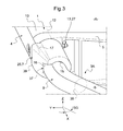
Figure 3 is a part perspective front and lateral view of a mount device and of a fore deflector assembly as per the invention. -
Figure 4 is a part cutaway lateral view of a mount device and of a fore deflector assembly as per the invention. -
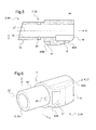
Figure 5 is a cutaway lateral view of a adjoined anchorage of a fore deflector assembly as per the invention. -
Figure 6 is a perspective front and lateral view of an adjoined anchorage of a fore deflector assembly as per the invention. -
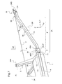
Figure 7 is a perspective front and lateral view of a fore deflector assembly and of a protuberant body step as per the invention. -
Figure 8 is a perspective front and lateral view of an adjoined anchorage as per the invention when assembled to a deflector ramp and to a protuberant body step as per the invention. -
Figure 9 is a perspective front and lateral view of an adjoined anchorage when assembled to a deflector ramp and to a protuberant body step. - Some figures show three mutually orthogonal directions X, Y and Z. The directions X, Y and Z together define a referential XYZ.
- A reference direction X referred to as being longitudinal corresponds to the length dimension and the forward cruise axis of the aircrafts described. Terms such as front / rear or fore / aft are relative thereto. The longitudinal direction X is deemed to be parallel to a roll axis of the aircraft.
- Another direction Y, said to be transverse, corresponds to the thickness or lateral dimension of the structures described.
- The dimensions X and Y define together the anteroposterior plane XZ of the aircraft. The anteroposterior plane AP of a rotorcraft is the upwards and transversally median plane that divides this rotorcraft in two lateral halves, i.e. the port side and the starboard side or left and right sides.
- The terms side or left / right or port / starboard are relative to the transverse direction Y. For instance, a transverse axis orthogonal to the anteroposterior plane XZ is considered as being mainly directed along this direction Y. This direction Y is deemed here as being parallel to a pitch axis of the aircraft.
- Another direction Z is referred to as the elevation or upwards direction. In level flight of an aircraft, the altitude or ground distance is along the direction Z. The direction Z corresponds to the radial length / height of the structures described. Here, the direction Z is deemed as being parallel to a yaw axis of the aircraft.
- On the
figure 1 , an aircraft A is illustrated, that is a rotorcraft. For instance, the aircraft A of other embodiments of the invention is chosen among various other aircrafts capable of cargo, rescue (e.g. SAR), tactical or the like missions, and of being equipped with a hoist. For instance, these embodiments consist of fixed wings or rotary wing aircrafts like helicopters, hybrid rotary wing aircrafts; UAV rotorcrafts and inhabitable rotorcrafts including remote piloting functions. - The aircraft A includes at least one
protuberant body 1 and afuselage 2, to which is directly or indirectly attached theprotuberant body 1. Thebody 1 is called protuberant since thisbody 1 extends outwards thefuselage 2. - As shown on
figure 2 , the aircraft A includes at least one hoist H. The hoist H classically has a gallows body secured to a fuselage of 2 the aircraft A. A winch mechanism is fixed to the gallows body and a rope / cable R is attached to the winch mechanism, so as to be unwind from or wind into the winch mechanism. This allows for respectively descending or ascending a load carrying harness or the like, secured to the rope / cable R. Thus, the hoist H allows Human persons and / or objects to be stowed when attached to the load carrying harness. - As shown on
figure 2 , during service of the aircraft A, the rope R can move within a hangingcone 22 extended from asuspension point 23 of the rope R (to the gallows body) downwards relative to thefuselage 2. Onfigure 2 , the hangingcone 22 has an angle of e.g. about 30°. - The aircraft A of
figure 1 or 2 has oneprotuberant body 1 has attached thereto and twodeflector assemblies 3A-3B (while anyprotuberant body 1 is generally designated by reference 3). In the shown embodiments, theprotuberant body 1 is a boarding step, but other embodiments include distinct / a plurality ofprotuberant bodies 1. - On
figure 2 , thedeflector assemblies 3A-3B are located under a movable panel of thefuselage 2 and in overhanging concordance with asuspension point 23 of thefuselage 2 to which an external item ER hangs over. Thesedeflector assemblies 3A-3B are aside of thesuspension point 23 along a forward cruise axis or direction X of the aircraft A. - One of the deflector assemblies 3 - called
first deflector assembly 3A - is besides afirst side end 25 of theprotuberant body 1 along the direction X. Another of the deflector assemblies 3 -calledsecond deflector assembly 3B - is besides asecond side end 26 of theprotuberant body 1 along the direction X. - On
figures 1 or 2 , thefirst deflector assembly 3A is fore theprotuberant body 1 and thesecond deflector assembly 3B is aft, along the direction X. Here, thefirst deflector assembly 3A is mounted between theprotuberant body 1 and the skin of thefuselage 2. Thesecond deflector assembly 3B is mounted between theprotuberant body 1 and a landing gear fender itself mounted on thefuselage 2 of the aircraft A. - The
first deflector assembly 3A is heading and has a linear translation axis LT extending parallel the anteroposterior plane XZ. Anoblique section 38 of adeflector ramp 8 of thefirst deflector assembly 3A is transverse to the anteroposterior plane XZ, towards the anteroposterior plane XZ longitudinally from aft to fore along the forward cruise axis of the aircraft A. - On
figures 1 or 2 , theprotuberant body 1 has a pair ofmount devices 5 respectively at thefirst side end 25 and at thesecond side end 26. Eachmount device 5 includes at least onesupport sheath 12. Here, eachsheath 12 is able to cooperate with onerespective deflector assembly 3A-3B. Eachmount device 5 includes at least oneattachment organ 24A through which theprotuberant body 1 is demountably mounted on thefuselage 2. - On examples of
figures 1 or 2 , theprotuberant body 1 extends parallel to the anteroposterior plane XZ of the aircraft A, and slightly along the longitudinal direction X. On other examples, theprotuberant body 1 is e.g. extended perpendicular to the anteroposterior plane XZ. - This
deflector assembly 3A comprises at least: - one adjoined
anchorage 7 able to be rigidly secured to theprotuberant body 1 at theend 25; - one
remote anchorage 6 able to be secured to thefuselage 2 by anattachment organ 24B; and - one
deflector ramp 8, extending from the adjoinedanchorage 7 and towards theremote deflector anchorage 6, along the longitudinal direction X. - In the
deflector assembly 3A, aninnermost end 37 of thedeflector ramp 8 cooperates with the adjoinedanchorage 7 and anoutermost end 36 of thedeflector ramp 8 cooperates with theremote deflector anchorage 6. - Also in the
deflector assembly 3A, thedeflector ramp 8 has acentral oblique section 38 that is secant to the longitudinal direction X of thedeflector assembly 3A and that extends with an oblique angle SG (figure 3 ) relative to the longitudinal direction X, in a plane orthogonal to the anteroposterior plane XZ, to act as a sliding guide for the external item ER. - From the above, it is clear that each
deflector assembly 3 is mounted on thefuselage 2 so as to protect the proximalprotuberant body 1 against adverse contact reaction -like jamming - from the external item ER and / or of the rope R outside thefuselage 2. - More detailed description refers to
figures 3-9 , and speciallyfigures 4 and7 . - On
figure 7 , theremote anchorage 6 has asupport bracket 21 for demountably mounting theremote anchorage 6 to thefuselage 2. - On
figure 4 , the adjoinedanchorage 7 includes asocket face 39 that internally has a slidingbearing 15 in which is housed theinnermost end 37. - The sliding
bearing 15 has a linear translation axis LT along which theinnermost end 37 is slidably guided relative to the adjoinedanchorage 7 to have one degree of freedom along the linear translation axis LT. - On
figure 9 for instance, theinnermost end 37 has aslot hole 14 extended along the linear translation axis LT. The adjoinedanchorage 7 has a traversing bore 20 radially passing from the slidingbearing 15 to anadjunctive arrangement 27 outside thesocket face 39. Theadjunctive arrangement 27 is able to complementary fit into thesupport sheath 12 of theprotuberant body 1. Thedeflector assembly 3A includes a bindingaxis 11 passing through theslot hole 14 and through the traversing bore 20, so that the bindingaxis 11 is able to be rigidly secured in adrill hole 18 of thesupport sheath 12, for having the adjoinedanchorage 7 fixedly hold into thesupport sheath 12 and theinnermost end 37 slidably guided along the linear translation axis LT. - As shown on
figure 4 , theslot hole 14 has a predetermined dimension VLT along the linear translation axis LT that correspondingly limits the freedom in translation of theinnermost end 37 of the deflector assembly 3 (here thefront assembly 3A), relative to the adjoinedanchorage 7. Eachsupport sheath 12 has adrill hole 18 facing both theslot hole 14 and the traversing bore 20. - On
figure 4 , the linear translation axis LT of the slidingbearing 15 is parallel to the longitudinal direction X. Other embodiments allows distinct linear translation axis, e.g. along he transverse direction Y or with acute angles relative to one of these directions X or Y. Most embodiments provide for linear translation axis LT in a plane transverse to the anteroposterior plane XY and parallel to the longitudinal direction X. - On
figure 3 , the adjoinedanchorage 7 has anouter recess 17 in thesocket face 39 and afront beam 4. Thefront beam 4 is received into theouter recess 17 flush with thesocket face 39. Thefront beam 4 is arranged to be able to locally cover thesupport sheath 12 and astep plate 10 of theprotuberant body 1, so that thefront beam 4 is outwardly leveled with thesocket face 39. - On
figures 4-6 , thesocket face 39 has a pair ofrounded frontages 40A-40B, respectively fore and aft. Thissocket face 39 is a one-piece member made of a single material chosen among one of: die cast metal, machined metal, machined synthetic resin, molded synthetic resin, unitary formed composite. - Since such a
socket face 39 is one-piece, the slidingbearing 15 is either formed from mould casting and / or machined. - In the
deflector assembly 3A offigures 3-4 , afrontage cam track 9 is fixedly secured to thedeflector ramp 8 and is locally covering both thecentral oblique section 38 and theinnermost end 37 of thedeflector ramp 8. In this embodiment, thecam track 9 extends all along thedeflector ramp 8 from fore to aft, but only partially covers radially thisramp 8. - On
figures 4-6 , thesocket face 39 has aclearance cavity 16 extending along the linear translation axis LT for receiving an end portion of thefrontage cam track 9 aside theinnermost end 37. - The end portion of the
frontage cam track 9 is locally housed freely into theclearance cavity 16, so that when thedeflector ramp 8 translates relative to thesocket face 39, the ending portion of thefrontage cam track 9 respectively slides inside theclearance cavity 16. Such efforts and vibrations are therefore not transferred to thefuselage 2. This allows releasing efforts and vibrations that would otherwise possibly impair theaircraft 1. - As shown on
figure 3 , thedeflector ramp 8 has a tube shaped section, integrally formed with theinnermost end 37 that is parallel with the linear translation axis LT, with thecentral oblique section 38 extending with the oblique angle SG and with theoutermost end 36 parallel with the linear translation axis LT. The tube shaped section forming a one-piece deflector ramp 8. - The example on
figure 3 of the oblique angle SG is an acute angle. Other embodiments provide for an oblique angle SG is an open angle. - On
figure 7 , theremote deflector anchorage 6 includes in the support bracket 21 a rotational bushing, so that theoutermost end 36 is pivotably secured to thefuselage 2, with a relative degree of rotational freedom. So, efforts and vibrations are therefore not transferred to thefuselage 2. This allows releasing efforts and vibrations that would otherwise possibly impair theaircraft 1. - Should the aircraft A include one or
more deflector assemblies protuberant body 1, the invention has the advantage that eachdeflector assembly - Besides, the invention allows movement of the
deflector assembly anchorage 7 and rotational freedom at theremote anchorage 6, to prevent high loads from occurring between thedeflector assemblies protuberant body 1. - Therefore a lighter design of the
protuberant body 1 can be performed. During flight, the incurred movements of theprotuberant body 1 relative to areas of thefuselage 2 are not resulting in altering forces, since thedeflector assemblies protuberant body 1 and to the aircraft A. - For production standpoint, the invention involves only a few parts and is very cost effective based on the use of semi-finished products like tubes.
- The
deflector assemblies - Thanks to the invention, the
protuberant body 1 forms a boarding step that consists only of a beam and twomount devices 5 riveted or screwed together. Themount devices 5 are simply connected to the aircraft A outer skin via theattachments 24A-24B. On each side of theboarding step 1 is possibly arranged onedeflector assembly - Each of the
deflector assemblies mount devices 5 have each on one side adrill hole 18, in which aslide bearing 15 is located. Theslide bearing 15 is part of the sleeve formed by thesheath 12. In this sleeve, the tube forming theramp 8 is located. - The
drill hole 18 runs through the edge of thedeflector assemblies drill hole 18 there is a screw placed and connected with a nut to form the adjoinedanchorage 27. Thereby the screw prevents the sleeve from sliding out of thedrill hole 18. - Because the
slide bearing 15 and the surfaces of thedeflector assembly body 1. - Each of the
deflector assemblies frontage cam track 9. - The deflector edge is riveted or screwed to the beam. The deflector edge is connected to the mount with the screw. The deflector edge, the deflector sleeve and the deflector edge consist preferably of plastics and are the sacrifice friction partner when in contact with the rescue hoist rope R. Therefore the support sleeve favorably consisting of metal is placed in the screw force closure of screw to prevent soft material from being in the screw force closure and therefore the screw preload from vanishing due to embedding and relaxation.
- Therefore in between the deflector edge and the
support sleeve 19 there is a predetermined clearance in screw direction, whereas the support sleeve lays flush on themount device 5. - The tube of the
deflector ramp 8 has a slot hole resulting in the tube's movability in the tube's axial degree of freedom, but it is fixed in the other degrees of freedom. - The slot hole enables an axial movement of the
deflector ramp 8 up to the stop given by the screw with the slot hole. It is also conceivable that on one side of thebody 1, the slot hole is replaced by a simple hole in order to selectively ensure the axial movability only on one side of thebody 1. - The deflector sleeve has a groove to house the deflector edge and a groove to house the deflector edge with predetermined clearances. The contact surfaces with the rope of the deflector edges and are mainly vertically oriented. Accordingly the deflector contour at the deflector sleeve's transition to the deflector edge and has roundness's, whose axes are mainly oriented vertically.
- Therefore a transition between the deflector edge and the deflector edge through the deflector sleeve is realized, which enables the rescue rope R to ride easily over the deflector.
- The rope deflector is easily mountable and demountable by the use of only two screws.
- The following table T1 is listing the references signs in the drawings.
1 protuberant body 2 fuselage 3 deflector assembly - 3A / 3B 4 front beam 5 mount device 6 remote anchorage 7 adjoined anchorage 8 deflector ramp 9 frontage cam track 10 step plate 11 binding axe 12 support sheath 13 nut 14 slot hole 15 sliding bearing 16 clearance cavity 17 outer recess 18 drill hole 19 deflector sleeve 20 traversing bore 21 support bracket 22 hanging cone (30°) 23 suspension point 24A - 24B attachment organs 25 first side end 26 second side end 27 adjoined anchorage 35 adjunctive arrangement 36 outermost end 37 innermost end 38 central oblique section 39 socket face 40A - 40B rounded frontage A Aircraft H hoist ER External item R Rope / cable X longitudinal direction Y transverse direction Z upright direction XZ anteroposterior plane LT linear translation axis SG oblique angle VLT predetermined dimension - The invention may be subjected to variations as to its implementation, said variations not being possibly identified exhaustively.
Claims (15)
- Deflector assembly (3) for an aircraft (A); the deflector assembly (3) being able to be mounted on a fuselage (2) of the aircraft (A) so as to protect a protuberant body (1) against contact adverse reaction from an external item (ER) outside the fuselage (2); the protuberant body (1) being mounted on and extending outwards the fuselage (2), the deflector assembly (3) comprises at least:- one adjoined anchorage (7) able to be rigidly secured to the protuberant body (1),- one remote anchorage (6) able to be secured to the fuselage (2), and- one deflector ramp (8), extending from the adjoined anchorage (7) and towards the remote deflector anchorage (6) along a longitudinal direction (X) of the deflector assembly (3),- an innermost end (37) of the deflector ramp (8) cooperates with the adjoined anchorage (7) and an outermost end (36) of the deflector ramp (8) cooperates with the remote deflector anchorage (6); the deflector ramp (8) having a central oblique section (38) that is secant to a longitudinal direction (X) of the deflector assembly (3) and that extends with an oblique angle (SG) relative to the longitudinal direction (X), to act as a sliding guide for the external item (ER),characterized in that the adjoined anchorage (7) includes a socket face (39) that internally has a sliding bearing (15) in which is housed the innermost end (37), the sliding bearing (15) has a linear translation axis (LT) along which the innermost end (37) is slidably guided relative to the adjoined anchorage (7) to have one degree of freedom along the linear translation axis (LT), the remote anchorage (6) having a support bracket (21) for demountably mounting the remote anchorage (6) to the fuselage (2).
- Deflector assembly (3) of claim 1,
characterized in that the innermost end (37) has a slot hole (14) extended along the linear translation axis (LT); the adjoined anchorage (7) has a traversing bore (20) radially passing from the sliding bearing (15) to an adjunctive arrangement (27) outside the socket face (39), the adjunctive arrangement (27) being able to complementary fit into a support sheath (12) of the protuberant body (1), the deflector assembly (3) including a binding axis (11) passing through the slot hole (14) and through the traversing bore (20), the binding axis (11) being able to be rigidly secured in a drill hole (18) of the support sheath (12), for having the adjoined anchorage (7) fixedly hold into the support sheath (12) and the innermost end (37) slidably guided along the linear translation axis (LT). - Deflector assembly (3) of claim 1,
characterized in that the slot hole (14) has a predetermined dimension (VLT) along the linear translation axis (LT) that correspondingly limits the freedom in translation of the innermost end (37) relative to the adjoined anchorage (7). - Deflector assembly (3) of claim 1,
characterized in that the linear translation axis (LT) of the sliding bearing (15) is parallel to the longitudinal direction (X). - Deflector assembly (3) of claim 1,
characterized in that the adjoined anchorage (7) has an outer recess (17) in the socket face (39) and a front beam (4), the front beam (4) being received into the outer recess (17) flush with the socket face (39), the front beam (4) being arranged to be able to locally cover a support sheath (12) and a step plate of the protuberant body (1), so that the front beam (4) is outwardly leveled with the socket face (39). - Deflector assembly (3) of claim 1,
characterized in that the socket face (39) has at least one rounded frontage (40A; 40B) and is a one-piece member made of a single material chosen among one of: die cast metal, machined metal, machined synthetic resin, molded synthetic resin, unitary formed composite, the socket face (39) includes at least one sliding bearing (15). - Deflector assembly (3) of claim 1,
characterized in that a frontage cam track (9) is fixedly secured to the deflector ramp (8) and is locally covering the central oblique section (38) and partly the innermost end (37) of the deflector ramp (8); the socket face (39) has a clearance cavity (16) extending along the linear translation axis (LT) for receiving an end portion of the frontage cam track (9) aside the innermost end (37), the end portion of the frontage cam track (9) being locally housed freely into the clearance cavity (16), so that when the deflector ramp (8) translates relative to the socket face (39), the ending portion of the frontage cam track (9) respectively slides inside the clearance cavity (16). - Deflector assembly (3) of claim 1,
characterized in that the deflector ramp (8) has a tube shaped section, integrally formed with the innermost end (37) parallel with the linear translation axis (LT), the central oblique section (38) extending with the oblique angle (SG) being an acute angle and the outermost end (36) parallel with the linear translation axis (LT). - Deflector assembly (3) of claim 1,
characterized in that the remote deflector anchorage (6) includes in the support bracket (21) a rotational bushing, so that the outermost end (36) is pivotably secured to the fuselage (2), with a relative degree of rotational freedom. - Aircraft (A)
characterized in that the aircraft (A) includes at least one deflector assembly (3) according to one of claims 1-9 and at least one protuberant body (1). - Aircraft (A) of claim 10,
characterized in that at least one protuberant body (1) has attached thereto, two deflector assemblies (3), one deflector assembly (3) being besides a first side end (25) of the protuberant body (1) and another deflector assembly (3) being besides a second side end (26) protuberant body (1). - Aircraft (A) of claim 10, characterized in that at least one protuberant body (1) has a mount device (5) including at least one support sheath (12) able to cooperate with the deflector assembly (3) and one attachment organ (24A) through which the protuberant body (1) is demountably mounted on the fuselage (2); the support sheath (12) having a drill hole (18) facing the slot hole (14) and the traversing bore (20).
- Aircraft (A) of claim 10,
characterized in that at least one protuberant body (1) is extended parallel to an anteroposterior plane (XZ) of the aircraft (A), a deflector assembly (3) being a heading deflector assembly (3) and having the linear translation axis (LT) extending parallel the anteroposterior plane (XZ), the oblique section (38) of the deflector ramp (8) being transverse to the anteroposterior plane (XZ), towards the anteroposterior plane (XZ) longitudinally from aft to fore along a forward cruise axis of the aircraft (A). - Aircraft (A) of claim 10,
characterized in that at least one deflector assembly (3) is located under a movable panel of the fuselage (2) and in overhanging concordance with a suspension point (23) of the fuselage (2) to which the external item (ER) hangs over, at least one deflector assembly (3) being aside of the suspension point (23) along a forward cruise axis of the aircraft (A). - Aircraft (A) of claim 10,
characterized in that the aircraft (A) being a rotorcraft and the longitudinal direction (X) of at least one deflector assembly (3) is chosen to extend along one of: a cruise forward axis of the aircraft (A) and a transverse axis orthogonal to the cruise forward axis of the aircraft (A) and to a anteposterior plane (XZ) of the aircraft (A).
Priority Applications (3)
| Application Number | Priority Date | Filing Date | Title |
|---|---|---|---|
| PL15400039T PL3135577T3 (en) | 2015-08-31 | 2015-08-31 | Deflector assembly for an aircraft |
| EP15400039.2A EP3135577B1 (en) | 2015-08-31 | 2015-08-31 | Deflector assembly for an aircraft |
| US15/236,565 US10384762B2 (en) | 2015-08-31 | 2016-08-15 | Deflector assembly for an aircraft |
Applications Claiming Priority (1)
| Application Number | Priority Date | Filing Date | Title |
|---|---|---|---|
| EP15400039.2A EP3135577B1 (en) | 2015-08-31 | 2015-08-31 | Deflector assembly for an aircraft |
Publications (2)
| Publication Number | Publication Date |
|---|---|
| EP3135577A1 true EP3135577A1 (en) | 2017-03-01 |
| EP3135577B1 EP3135577B1 (en) | 2017-07-26 |
Family
ID=54260706
Family Applications (1)
| Application Number | Title | Priority Date | Filing Date |
|---|---|---|---|
| EP15400039.2A Active EP3135577B1 (en) | 2015-08-31 | 2015-08-31 | Deflector assembly for an aircraft |
Country Status (3)
| Country | Link |
|---|---|
| US (1) | US10384762B2 (en) |
| EP (1) | EP3135577B1 (en) |
| PL (1) | PL3135577T3 (en) |
Citations (5)
| Publication number | Priority date | Publication date | Assignee | Title |
|---|---|---|---|---|
| US3823901A (en) * | 1973-07-24 | 1974-07-16 | Us Navy | Aerial launch system |
| GB2303837A (en) * | 1995-08-02 | 1997-03-05 | Kenneth George Barnes | Winch cable deflector |
| JP3084369B1 (en) | 1999-05-11 | 2000-09-04 | 朝日航洋株式会社 | Helicopter sled protection structure |
| US20060237558A1 (en) * | 2005-04-20 | 2006-10-26 | Emerald Pacific Airlines | Spray washer structure of insulator used for aircraft |
| US8567710B2 (en) | 2007-09-18 | 2013-10-29 | Aero Asahi Corporation | Cable protection device |
Family Cites Families (19)
| Publication number | Priority date | Publication date | Assignee | Title |
|---|---|---|---|---|
| US1362521A (en) * | 1919-06-02 | 1920-12-14 | Allen J Husband | Coupling |
| US1645747A (en) * | 1926-10-22 | 1927-10-18 | John J Fry | Swivel |
| US1891188A (en) * | 1930-02-06 | 1932-12-13 | Jr Arthur Ralston Stalb | Airplane landing gear |
| US2508832A (en) * | 1948-08-28 | 1950-05-23 | Borg Warner | Coupling device |
| US2984437A (en) * | 1957-08-27 | 1961-05-16 | Cleveland Pneumatic Ind Inc | Aircraft landing gear |
| US2937042A (en) * | 1958-10-02 | 1960-05-17 | Reliance Electric & Eng Co | Shaft coupling |
| US3193221A (en) * | 1962-11-13 | 1965-07-06 | Hiller Aircraft Company Inc | Aircraft landing gear strut structure |
| US3323756A (en) * | 1965-08-18 | 1967-06-06 | Jr John B Mapes | Aerial towing apparatus |
| US4165892A (en) * | 1977-08-12 | 1979-08-28 | Victaulic Company Of America | Coupling for releasably securing one end of a rod-like member |
| US5243874A (en) * | 1992-02-24 | 1993-09-14 | Pittsburgh Tubular Shafting, Inc. | Method and apparatus for telescopically assembling a pair of elongated members |
| US5950252A (en) * | 1996-01-11 | 1999-09-14 | Fettes; Ian | Device for aiding removal and replacement of a spa cover |
| SE9603994L (en) * | 1996-10-31 | 1997-10-13 | Tidaflag Ab | Procedure and arrangement of a flagpole |
| US6334590B1 (en) * | 1999-04-09 | 2002-01-01 | Bell Helicopter Textron Inc. | Removable hoist for aircraft |
| US6872026B2 (en) * | 2003-04-04 | 2005-03-29 | Quickie Manufacturing Corporation | Handle connector |
| WO2012037595A1 (en) * | 2010-09-20 | 2012-03-29 | Helimods Pty Ltd | Load attachment system for helicopters |
| US10046861B2 (en) | 2010-11-23 | 2018-08-14 | Richard Jones | Aircraft safety device systems |
| US8662794B2 (en) * | 2011-07-27 | 2014-03-04 | Hubbell Incorporated | Helical pile adapter |
| CN103921933A (en) * | 2013-01-10 | 2014-07-16 | 深圳市大疆创新科技有限公司 | Deformation structure of air vehicle and micro air vehicle |
| RU164934U1 (en) | 2016-02-11 | 2016-09-27 | Владимир Эрвинович Кононов | CAR HOOD DEFECTOR |
-
2015
- 2015-08-31 PL PL15400039T patent/PL3135577T3/en unknown
- 2015-08-31 EP EP15400039.2A patent/EP3135577B1/en active Active
-
2016
- 2016-08-15 US US15/236,565 patent/US10384762B2/en active Active
Patent Citations (5)
| Publication number | Priority date | Publication date | Assignee | Title |
|---|---|---|---|---|
| US3823901A (en) * | 1973-07-24 | 1974-07-16 | Us Navy | Aerial launch system |
| GB2303837A (en) * | 1995-08-02 | 1997-03-05 | Kenneth George Barnes | Winch cable deflector |
| JP3084369B1 (en) | 1999-05-11 | 2000-09-04 | 朝日航洋株式会社 | Helicopter sled protection structure |
| US20060237558A1 (en) * | 2005-04-20 | 2006-10-26 | Emerald Pacific Airlines | Spray washer structure of insulator used for aircraft |
| US8567710B2 (en) | 2007-09-18 | 2013-10-29 | Aero Asahi Corporation | Cable protection device |
Also Published As
| Publication number | Publication date |
|---|---|
| US10384762B2 (en) | 2019-08-20 |
| US20170057617A1 (en) | 2017-03-02 |
| EP3135577B1 (en) | 2017-07-26 |
| PL3135577T3 (en) | 2017-12-29 |
Similar Documents
| Publication | Publication Date | Title |
|---|---|---|
| US10023313B2 (en) | Rope suspension device with at least one rope suspension module | |
| EP3156331B1 (en) | Deployable door-mounted seat | |
| US6986484B2 (en) | VTOL aircraft external load drag reduction system | |
| CN108116654B (en) | Rotary wing aircraft with sliding members, especially sliding doors or windows | |
| US8915466B2 (en) | Aircraft provided with hoist means, and an associated method | |
| US10486790B2 (en) | Maintenance step for a helicopter | |
| EP2796371A1 (en) | Cabin attendant seat with additional support | |
| US8689496B2 (en) | Frangible hinge mechanism for a platform partition, associated partition, assembly and method | |
| US10329006B2 (en) | Aircraft external viewing system, apparatus, and method | |
| EP3636548B1 (en) | Vehicle business class seat and stowage system | |
| EP3050794B1 (en) | Aircraft with inwardly foldable rear door | |
| EP3378757A1 (en) | An aircraft with a subfloor region that accommodates an auxiliary compartment | |
| US10479502B2 (en) | Aircraft provided with a winch device | |
| CA2951562C (en) | Deflector assembly for an aircraft | |
| EP3231662B1 (en) | Override bypass assembly for a seat locking mechanism | |
| US20180281934A1 (en) | Front landing gear of reduced height and aircraft, in particular a flying wing, equipped with such a front landing gear | |
| EP3135577B1 (en) | Deflector assembly for an aircraft | |
| US20160376006A1 (en) | Rope deployment mechanism for an aircraft | |
| CN111688931A (en) | Power transmission system | |
| RU2648530C1 (en) | Deflector device for aircraft | |
| US7931428B2 (en) | Aircraft payload retention system for interior loads | |
| EP4506249A1 (en) | Flight controller ingress and egress system | |
| CA2952490C (en) | A maintenance step for a helicopter | |
| CN107757862B (en) | Rotorcraft having a fairing rotatable and translatable relative to the fuselage | |
| RU2104221C1 (en) | Helicopter |
Legal Events
| Date | Code | Title | Description |
|---|---|---|---|
| PUAI | Public reference made under article 153(3) epc to a published international application that has entered the european phase |
Free format text: ORIGINAL CODE: 0009012 |
|
| AK | Designated contracting states |
Kind code of ref document: A1 Designated state(s): AL AT BE BG CH CY CZ DE DK EE ES FI FR GB GR HR HU IE IS IT LI LT LU LV MC MK MT NL NO PL PT RO RS SE SI SK SM TR |
|
| AX | Request for extension of the european patent |
Extension state: BA ME |
|
| 17P | Request for examination filed |
Effective date: 20170208 |
|
| RBV | Designated contracting states (corrected) |
Designated state(s): AL AT BE BG CH CY CZ DE DK EE ES FI FR GB GR HR HU IE IS IT LI LT LU LV MC MK MT NL NO PL PT RO RS SE SI SK SM TR |
|
| GRAP | Despatch of communication of intention to grant a patent |
Free format text: ORIGINAL CODE: EPIDOSNIGR1 |
|
| INTG | Intention to grant announced |
Effective date: 20170518 |
|
| GRAS | Grant fee paid |
Free format text: ORIGINAL CODE: EPIDOSNIGR3 |
|
| GRAA | (expected) grant |
Free format text: ORIGINAL CODE: 0009210 |
|
| AK | Designated contracting states |
Kind code of ref document: B1 Designated state(s): AL AT BE BG CH CY CZ DE DK EE ES FI FR GB GR HR HU IE IS IT LI LT LU LV MC MK MT NL NO PL PT RO RS SE SI SK SM TR |
|
| REG | Reference to a national code |
Ref country code: GB Ref legal event code: FG4D |
|
| REG | Reference to a national code |
Ref country code: CH Ref legal event code: EP |
|
| REG | Reference to a national code |
Ref country code: AT Ref legal event code: REF Ref document number: 912116 Country of ref document: AT Kind code of ref document: T Effective date: 20170815 |
|
| REG | Reference to a national code |
Ref country code: FR Ref legal event code: PLFP Year of fee payment: 3 |
|
| REG | Reference to a national code |
Ref country code: IE Ref legal event code: FG4D |
|
| REG | Reference to a national code |
Ref country code: DE Ref legal event code: R096 Ref document number: 602015003766 Country of ref document: DE |
|
| REG | Reference to a national code |
Ref country code: NL Ref legal event code: MP Effective date: 20170726 |
|
| REG | Reference to a national code |
Ref country code: LT Ref legal event code: MG4D |
|
| REG | Reference to a national code |
Ref country code: AT Ref legal event code: MK05 Ref document number: 912116 Country of ref document: AT Kind code of ref document: T Effective date: 20170726 |
|
| PG25 | Lapsed in a contracting state [announced via postgrant information from national office to epo] |
Ref country code: FI Free format text: LAPSE BECAUSE OF FAILURE TO SUBMIT A TRANSLATION OF THE DESCRIPTION OR TO PAY THE FEE WITHIN THE PRESCRIBED TIME-LIMIT Effective date: 20170726 Ref country code: LT Free format text: LAPSE BECAUSE OF FAILURE TO SUBMIT A TRANSLATION OF THE DESCRIPTION OR TO PAY THE FEE WITHIN THE PRESCRIBED TIME-LIMIT Effective date: 20170726 Ref country code: SE Free format text: LAPSE BECAUSE OF FAILURE TO SUBMIT A TRANSLATION OF THE DESCRIPTION OR TO PAY THE FEE WITHIN THE PRESCRIBED TIME-LIMIT Effective date: 20170726 Ref country code: HR Free format text: LAPSE BECAUSE OF FAILURE TO SUBMIT A TRANSLATION OF THE DESCRIPTION OR TO PAY THE FEE WITHIN THE PRESCRIBED TIME-LIMIT Effective date: 20170726 Ref country code: NO Free format text: LAPSE BECAUSE OF FAILURE TO SUBMIT A TRANSLATION OF THE DESCRIPTION OR TO PAY THE FEE WITHIN THE PRESCRIBED TIME-LIMIT Effective date: 20171026 Ref country code: AT Free format text: LAPSE BECAUSE OF FAILURE TO SUBMIT A TRANSLATION OF THE DESCRIPTION OR TO PAY THE FEE WITHIN THE PRESCRIBED TIME-LIMIT Effective date: 20170726 Ref country code: NL Free format text: LAPSE BECAUSE OF FAILURE TO SUBMIT A TRANSLATION OF THE DESCRIPTION OR TO PAY THE FEE WITHIN THE PRESCRIBED TIME-LIMIT Effective date: 20170726 |
|
| PG25 | Lapsed in a contracting state [announced via postgrant information from national office to epo] |
Ref country code: IS Free format text: LAPSE BECAUSE OF FAILURE TO SUBMIT A TRANSLATION OF THE DESCRIPTION OR TO PAY THE FEE WITHIN THE PRESCRIBED TIME-LIMIT Effective date: 20171126 Ref country code: LV Free format text: LAPSE BECAUSE OF FAILURE TO SUBMIT A TRANSLATION OF THE DESCRIPTION OR TO PAY THE FEE WITHIN THE PRESCRIBED TIME-LIMIT Effective date: 20170726 Ref country code: ES Free format text: LAPSE BECAUSE OF FAILURE TO SUBMIT A TRANSLATION OF THE DESCRIPTION OR TO PAY THE FEE WITHIN THE PRESCRIBED TIME-LIMIT Effective date: 20170726 Ref country code: BG Free format text: LAPSE BECAUSE OF FAILURE TO SUBMIT A TRANSLATION OF THE DESCRIPTION OR TO PAY THE FEE WITHIN THE PRESCRIBED TIME-LIMIT Effective date: 20171026 Ref country code: GR Free format text: LAPSE BECAUSE OF FAILURE TO SUBMIT A TRANSLATION OF THE DESCRIPTION OR TO PAY THE FEE WITHIN THE PRESCRIBED TIME-LIMIT Effective date: 20171027 Ref country code: RS Free format text: LAPSE BECAUSE OF FAILURE TO SUBMIT A TRANSLATION OF THE DESCRIPTION OR TO PAY THE FEE WITHIN THE PRESCRIBED TIME-LIMIT Effective date: 20170726 |
|
| PG25 | Lapsed in a contracting state [announced via postgrant information from national office to epo] |
Ref country code: DK Free format text: LAPSE BECAUSE OF FAILURE TO SUBMIT A TRANSLATION OF THE DESCRIPTION OR TO PAY THE FEE WITHIN THE PRESCRIBED TIME-LIMIT Effective date: 20170726 Ref country code: MC Free format text: LAPSE BECAUSE OF FAILURE TO SUBMIT A TRANSLATION OF THE DESCRIPTION OR TO PAY THE FEE WITHIN THE PRESCRIBED TIME-LIMIT Effective date: 20170726 Ref country code: CZ Free format text: LAPSE BECAUSE OF FAILURE TO SUBMIT A TRANSLATION OF THE DESCRIPTION OR TO PAY THE FEE WITHIN THE PRESCRIBED TIME-LIMIT Effective date: 20170726 |
|
| REG | Reference to a national code |
Ref country code: DE Ref legal event code: R097 Ref document number: 602015003766 Country of ref document: DE |
|
| REG | Reference to a national code |
Ref country code: BE Ref legal event code: MM Effective date: 20170831 |
|
| REG | Reference to a national code |
Ref country code: IE Ref legal event code: MM4A |
|
| PG25 | Lapsed in a contracting state [announced via postgrant information from national office to epo] |
Ref country code: SM Free format text: LAPSE BECAUSE OF FAILURE TO SUBMIT A TRANSLATION OF THE DESCRIPTION OR TO PAY THE FEE WITHIN THE PRESCRIBED TIME-LIMIT Effective date: 20170726 Ref country code: EE Free format text: LAPSE BECAUSE OF FAILURE TO SUBMIT A TRANSLATION OF THE DESCRIPTION OR TO PAY THE FEE WITHIN THE PRESCRIBED TIME-LIMIT Effective date: 20170726 Ref country code: IT Free format text: LAPSE BECAUSE OF FAILURE TO SUBMIT A TRANSLATION OF THE DESCRIPTION OR TO PAY THE FEE WITHIN THE PRESCRIBED TIME-LIMIT Effective date: 20170726 Ref country code: SK Free format text: LAPSE BECAUSE OF FAILURE TO SUBMIT A TRANSLATION OF THE DESCRIPTION OR TO PAY THE FEE WITHIN THE PRESCRIBED TIME-LIMIT Effective date: 20170726 |
|
| PLBE | No opposition filed within time limit |
Free format text: ORIGINAL CODE: 0009261 |
|
| STAA | Information on the status of an ep patent application or granted ep patent |
Free format text: STATUS: NO OPPOSITION FILED WITHIN TIME LIMIT |
|
| PG25 | Lapsed in a contracting state [announced via postgrant information from national office to epo] |
Ref country code: LU Free format text: LAPSE BECAUSE OF NON-PAYMENT OF DUE FEES Effective date: 20170831 |
|
| 26N | No opposition filed |
Effective date: 20180430 |
|
| PG25 | Lapsed in a contracting state [announced via postgrant information from national office to epo] |
Ref country code: IE Free format text: LAPSE BECAUSE OF NON-PAYMENT OF DUE FEES Effective date: 20170831 |
|
| REG | Reference to a national code |
Ref country code: FR Ref legal event code: PLFP Year of fee payment: 4 |
|
| PG25 | Lapsed in a contracting state [announced via postgrant information from national office to epo] |
Ref country code: SI Free format text: LAPSE BECAUSE OF FAILURE TO SUBMIT A TRANSLATION OF THE DESCRIPTION OR TO PAY THE FEE WITHIN THE PRESCRIBED TIME-LIMIT Effective date: 20170726 Ref country code: BE Free format text: LAPSE BECAUSE OF NON-PAYMENT OF DUE FEES Effective date: 20170831 |
|
| PG25 | Lapsed in a contracting state [announced via postgrant information from national office to epo] |
Ref country code: MT Free format text: LAPSE BECAUSE OF NON-PAYMENT OF DUE FEES Effective date: 20170831 |
|
| REG | Reference to a national code |
Ref country code: CH Ref legal event code: PL |
|
| PG25 | Lapsed in a contracting state [announced via postgrant information from national office to epo] |
Ref country code: CH Free format text: LAPSE BECAUSE OF NON-PAYMENT OF DUE FEES Effective date: 20180831 Ref country code: LI Free format text: LAPSE BECAUSE OF NON-PAYMENT OF DUE FEES Effective date: 20180831 |
|
| PG25 | Lapsed in a contracting state [announced via postgrant information from national office to epo] |
Ref country code: HU Free format text: LAPSE BECAUSE OF FAILURE TO SUBMIT A TRANSLATION OF THE DESCRIPTION OR TO PAY THE FEE WITHIN THE PRESCRIBED TIME-LIMIT; INVALID AB INITIO Effective date: 20150831 |
|
| PG25 | Lapsed in a contracting state [announced via postgrant information from national office to epo] |
Ref country code: RO Free format text: LAPSE BECAUSE OF FAILURE TO SUBMIT A TRANSLATION OF THE DESCRIPTION OR TO PAY THE FEE WITHIN THE PRESCRIBED TIME-LIMIT Effective date: 20170726 |
|
| PG25 | Lapsed in a contracting state [announced via postgrant information from national office to epo] |
Ref country code: CY Free format text: LAPSE BECAUSE OF FAILURE TO SUBMIT A TRANSLATION OF THE DESCRIPTION OR TO PAY THE FEE WITHIN THE PRESCRIBED TIME-LIMIT Effective date: 20170726 |
|
| PG25 | Lapsed in a contracting state [announced via postgrant information from national office to epo] |
Ref country code: MK Free format text: LAPSE BECAUSE OF FAILURE TO SUBMIT A TRANSLATION OF THE DESCRIPTION OR TO PAY THE FEE WITHIN THE PRESCRIBED TIME-LIMIT Effective date: 20170726 |
|
| PG25 | Lapsed in a contracting state [announced via postgrant information from national office to epo] |
Ref country code: TR Free format text: LAPSE BECAUSE OF FAILURE TO SUBMIT A TRANSLATION OF THE DESCRIPTION OR TO PAY THE FEE WITHIN THE PRESCRIBED TIME-LIMIT Effective date: 20170726 |
|
| PG25 | Lapsed in a contracting state [announced via postgrant information from national office to epo] |
Ref country code: PT Free format text: LAPSE BECAUSE OF FAILURE TO SUBMIT A TRANSLATION OF THE DESCRIPTION OR TO PAY THE FEE WITHIN THE PRESCRIBED TIME-LIMIT Effective date: 20170726 |
|
| PG25 | Lapsed in a contracting state [announced via postgrant information from national office to epo] |
Ref country code: AL Free format text: LAPSE BECAUSE OF FAILURE TO SUBMIT A TRANSLATION OF THE DESCRIPTION OR TO PAY THE FEE WITHIN THE PRESCRIBED TIME-LIMIT Effective date: 20170726 |
|
| P01 | Opt-out of the competence of the unified patent court (upc) registered |
Effective date: 20230530 |
|
| PGFP | Annual fee paid to national office [announced via postgrant information from national office to epo] |
Ref country code: DE Payment date: 20250820 Year of fee payment: 11 |
|
| PGFP | Annual fee paid to national office [announced via postgrant information from national office to epo] |
Ref country code: PL Payment date: 20250821 Year of fee payment: 11 |
|
| PGFP | Annual fee paid to national office [announced via postgrant information from national office to epo] |
Ref country code: GB Payment date: 20250820 Year of fee payment: 11 |
|
| PGFP | Annual fee paid to national office [announced via postgrant information from national office to epo] |
Ref country code: FR Payment date: 20250829 Year of fee payment: 11 |