EP3135449A1 - Mold, systems and methods for injection molding a sealant to an object - Google Patents
Mold, systems and methods for injection molding a sealant to an object Download PDFInfo
- Publication number
- EP3135449A1 EP3135449A1 EP16183311.6A EP16183311A EP3135449A1 EP 3135449 A1 EP3135449 A1 EP 3135449A1 EP 16183311 A EP16183311 A EP 16183311A EP 3135449 A1 EP3135449 A1 EP 3135449A1
- Authority
- EP
- European Patent Office
- Prior art keywords
- mold
- sealant
- air
- vacuum
- volumes
- Prior art date
- Legal status (The legal status is an assumption and is not a legal conclusion. Google has not performed a legal analysis and makes no representation as to the accuracy of the status listed.)
- Granted
Links
Images





Classifications
-
- B—PERFORMING OPERATIONS; TRANSPORTING
- B29—WORKING OF PLASTICS; WORKING OF SUBSTANCES IN A PLASTIC STATE IN GENERAL
- B29C—SHAPING OR JOINING OF PLASTICS; SHAPING OF MATERIAL IN A PLASTIC STATE, NOT OTHERWISE PROVIDED FOR; AFTER-TREATMENT OF THE SHAPED PRODUCTS, e.g. REPAIRING
- B29C45/00—Injection moulding, i.e. forcing the required volume of moulding material through a nozzle into a closed mould; Apparatus therefor
- B29C45/17—Component parts, details or accessories; Auxiliary operations
- B29C45/46—Means for plasticising or homogenising the moulding material or forcing it into the mould
-
- B—PERFORMING OPERATIONS; TRANSPORTING
- B29—WORKING OF PLASTICS; WORKING OF SUBSTANCES IN A PLASTIC STATE IN GENERAL
- B29C—SHAPING OR JOINING OF PLASTICS; SHAPING OF MATERIAL IN A PLASTIC STATE, NOT OTHERWISE PROVIDED FOR; AFTER-TREATMENT OF THE SHAPED PRODUCTS, e.g. REPAIRING
- B29C33/00—Moulds or cores; Details thereof or accessories therefor
- B29C33/30—Mounting, exchanging or centering
-
- B—PERFORMING OPERATIONS; TRANSPORTING
- B29—WORKING OF PLASTICS; WORKING OF SUBSTANCES IN A PLASTIC STATE IN GENERAL
- B29C—SHAPING OR JOINING OF PLASTICS; SHAPING OF MATERIAL IN A PLASTIC STATE, NOT OTHERWISE PROVIDED FOR; AFTER-TREATMENT OF THE SHAPED PRODUCTS, e.g. REPAIRING
- B29C45/00—Injection moulding, i.e. forcing the required volume of moulding material through a nozzle into a closed mould; Apparatus therefor
- B29C45/14—Injection moulding, i.e. forcing the required volume of moulding material through a nozzle into a closed mould; Apparatus therefor incorporating preformed parts or layers, e.g. injection moulding around inserts or for coating articles
- B29C45/14336—Coating a portion of the article, e.g. the edge of the article
-
- B—PERFORMING OPERATIONS; TRANSPORTING
- B29—WORKING OF PLASTICS; WORKING OF SUBSTANCES IN A PLASTIC STATE IN GENERAL
- B29C—SHAPING OR JOINING OF PLASTICS; SHAPING OF MATERIAL IN A PLASTIC STATE, NOT OTHERWISE PROVIDED FOR; AFTER-TREATMENT OF THE SHAPED PRODUCTS, e.g. REPAIRING
- B29C45/00—Injection moulding, i.e. forcing the required volume of moulding material through a nozzle into a closed mould; Apparatus therefor
- B29C45/17—Component parts, details or accessories; Auxiliary operations
- B29C45/1701—Component parts, details or accessories; Auxiliary operations using a particular environment during moulding, e.g. moisture-free or dust-free
-
- B—PERFORMING OPERATIONS; TRANSPORTING
- B29—WORKING OF PLASTICS; WORKING OF SUBSTANCES IN A PLASTIC STATE IN GENERAL
- B29C—SHAPING OR JOINING OF PLASTICS; SHAPING OF MATERIAL IN A PLASTIC STATE, NOT OTHERWISE PROVIDED FOR; AFTER-TREATMENT OF THE SHAPED PRODUCTS, e.g. REPAIRING
- B29C45/00—Injection moulding, i.e. forcing the required volume of moulding material through a nozzle into a closed mould; Apparatus therefor
- B29C45/17—Component parts, details or accessories; Auxiliary operations
- B29C45/1756—Handling of moulds or mould parts, e.g. mould exchanging means
-
- B—PERFORMING OPERATIONS; TRANSPORTING
- B29—WORKING OF PLASTICS; WORKING OF SUBSTANCES IN A PLASTIC STATE IN GENERAL
- B29C—SHAPING OR JOINING OF PLASTICS; SHAPING OF MATERIAL IN A PLASTIC STATE, NOT OTHERWISE PROVIDED FOR; AFTER-TREATMENT OF THE SHAPED PRODUCTS, e.g. REPAIRING
- B29C45/00—Injection moulding, i.e. forcing the required volume of moulding material through a nozzle into a closed mould; Apparatus therefor
- B29C45/17—Component parts, details or accessories; Auxiliary operations
- B29C45/26—Moulds
- B29C45/34—Moulds having venting means
-
- B—PERFORMING OPERATIONS; TRANSPORTING
- B29—WORKING OF PLASTICS; WORKING OF SUBSTANCES IN A PLASTIC STATE IN GENERAL
- B29C—SHAPING OR JOINING OF PLASTICS; SHAPING OF MATERIAL IN A PLASTIC STATE, NOT OTHERWISE PROVIDED FOR; AFTER-TREATMENT OF THE SHAPED PRODUCTS, e.g. REPAIRING
- B29C45/00—Injection moulding, i.e. forcing the required volume of moulding material through a nozzle into a closed mould; Apparatus therefor
- B29C45/17—Component parts, details or accessories; Auxiliary operations
- B29C45/76—Measuring, controlling or regulating
-
- B—PERFORMING OPERATIONS; TRANSPORTING
- B64—AIRCRAFT; AVIATION; COSMONAUTICS
- B64F—GROUND OR AIRCRAFT-CARRIER-DECK INSTALLATIONS SPECIALLY ADAPTED FOR USE IN CONNECTION WITH AIRCRAFT; DESIGNING, MANUFACTURING, ASSEMBLING, CLEANING, MAINTAINING OR REPAIRING AIRCRAFT, NOT OTHERWISE PROVIDED FOR; HANDLING, TRANSPORTING, TESTING OR INSPECTING AIRCRAFT COMPONENTS, NOT OTHERWISE PROVIDED FOR
- B64F5/00—Designing, manufacturing, assembling, cleaning, maintaining or repairing aircraft, not otherwise provided for; Handling, transporting, testing or inspecting aircraft components, not otherwise provided for
- B64F5/40—Maintaining or repairing aircraft
-
- B—PERFORMING OPERATIONS; TRANSPORTING
- B29—WORKING OF PLASTICS; WORKING OF SUBSTANCES IN A PLASTIC STATE IN GENERAL
- B29C—SHAPING OR JOINING OF PLASTICS; SHAPING OF MATERIAL IN A PLASTIC STATE, NOT OTHERWISE PROVIDED FOR; AFTER-TREATMENT OF THE SHAPED PRODUCTS, e.g. REPAIRING
- B29C45/00—Injection moulding, i.e. forcing the required volume of moulding material through a nozzle into a closed mould; Apparatus therefor
- B29C45/14—Injection moulding, i.e. forcing the required volume of moulding material through a nozzle into a closed mould; Apparatus therefor incorporating preformed parts or layers, e.g. injection moulding around inserts or for coating articles
- B29C45/14336—Coating a portion of the article, e.g. the edge of the article
- B29C2045/14459—Coating a portion of the article, e.g. the edge of the article injecting seal elements
-
- B—PERFORMING OPERATIONS; TRANSPORTING
- B29—WORKING OF PLASTICS; WORKING OF SUBSTANCES IN A PLASTIC STATE IN GENERAL
- B29C—SHAPING OR JOINING OF PLASTICS; SHAPING OF MATERIAL IN A PLASTIC STATE, NOT OTHERWISE PROVIDED FOR; AFTER-TREATMENT OF THE SHAPED PRODUCTS, e.g. REPAIRING
- B29C2791/00—Shaping characteristics in general
- B29C2791/004—Shaping under special conditions
- B29C2791/006—Using vacuum
-
- B—PERFORMING OPERATIONS; TRANSPORTING
- B29—WORKING OF PLASTICS; WORKING OF SUBSTANCES IN A PLASTIC STATE IN GENERAL
- B29C—SHAPING OR JOINING OF PLASTICS; SHAPING OF MATERIAL IN A PLASTIC STATE, NOT OTHERWISE PROVIDED FOR; AFTER-TREATMENT OF THE SHAPED PRODUCTS, e.g. REPAIRING
- B29C2945/00—Indexing scheme relating to injection moulding, i.e. forcing the required volume of moulding material through a nozzle into a closed mould
- B29C2945/76—Measuring, controlling or regulating
- B29C2945/76003—Measured parameter
- B29C2945/76006—Pressure
-
- B—PERFORMING OPERATIONS; TRANSPORTING
- B29—WORKING OF PLASTICS; WORKING OF SUBSTANCES IN A PLASTIC STATE IN GENERAL
- B29C—SHAPING OR JOINING OF PLASTICS; SHAPING OF MATERIAL IN A PLASTIC STATE, NOT OTHERWISE PROVIDED FOR; AFTER-TREATMENT OF THE SHAPED PRODUCTS, e.g. REPAIRING
- B29C2945/00—Indexing scheme relating to injection moulding, i.e. forcing the required volume of moulding material through a nozzle into a closed mould
- B29C2945/76—Measuring, controlling or regulating
- B29C2945/76003—Measured parameter
- B29C2945/761—Dimensions, e.g. thickness
- B29C2945/76107—Dimensions, e.g. thickness volume
-
- B—PERFORMING OPERATIONS; TRANSPORTING
- B29—WORKING OF PLASTICS; WORKING OF SUBSTANCES IN A PLASTIC STATE IN GENERAL
- B29L—INDEXING SCHEME ASSOCIATED WITH SUBCLASS B29C, RELATING TO PARTICULAR ARTICLES
- B29L2031/00—Other particular articles
- B29L2031/26—Sealing devices, e.g. packaging for pistons or pipe joints
- B29L2031/265—Packings, Gaskets
-
- B—PERFORMING OPERATIONS; TRANSPORTING
- B32—LAYERED PRODUCTS
- B32B—LAYERED PRODUCTS, i.e. PRODUCTS BUILT-UP OF STRATA OF FLAT OR NON-FLAT, e.g. CELLULAR OR HONEYCOMB, FORM
- B32B2581/00—Seals; Sealing equipment; Gaskets
Definitions
- Embodiments of the present disclosure generally relate to systems and methods for sealant injection molding.
- Various structures to be sealed may have fasteners or other features that are to be sealed.
- a nutplate ring of an access hole of an airplane wing may be sealed.
- conventional approaches to sealing such structures rely on manual application of sealant.
- Manual application of sealant may provide an undesired amount of sealant, and/or require an undesired amount of time for application of sealant and subsequent trimming or removal of excess sealant.
- sealing structures such as access ports of airplane wings
- sealing structures such as access ports of airplane wings
- one or more aspects of the presently disclosed subject matter may be utilized in conjunction with the sealing of other structures or fastener configurations than the illustrated examples of access port nut plates.
- Certain embodiments of the present disclosure provide a mold tool that includes plural mold sub-volumes configured to receive a sealant, a mold channel in fluid communication with the mold sub-volumes, a sealant injection port in fluid communication with the mold channel, vacuum application ports in fluid communication with the mold sub-volumes, and an air control system.
- the air control system is operably coupled to the mold sub-volumes and the mold channel, and is configured to apply a vacuum to the mold sub-volumes via the vacuum application ports.
- the mold tool for providing sealant to features of a target workpiece.
- the mold tool includes a frame, a mold body, an air control system, and a vacuum assembly.
- the mold body is coupled to the frame, and defines a mold volume configured to receive the sealant.
- the mold volume includes plural mold sub-volumes, and a mold channel.
- the mold body includes a sealant injection port in fluid communication with the mold volume, and vacuum application ports in fluid communication with the mold sub-volumes.
- the air control system is operably coupled to the mold body, and is configured to apply a vacuum to mold volume via the vacuum application ports.
- the vacuum assembly is operably coupled to the mold body and the air control system.
- the vacuum assembly includes a vacuum plate and vacuum generators mounted on the vacuum plate. The vacuum generators are configured to apply the vacuum to the mold volume under control of the air control system.
- Certain embodiments of the present disclosure provide a method.
- the method includes injection sealant into a number of mold sub-volumes disposed over corresponding features of an object to be sealed.
- the method also includes drawing the sealant from a higher pressure zone into a lower pressure zone in at least one of the sub-volumes to cover at least one of the features.
- Embodiments of the present disclosure provide systems and methods for sealing using a sealant application mold.
- a sealant injection system e.g., mold tool 10, 11, 1400
- secures itself to a workpiece e.g., a panel having an opening surrounded by a nutplate
- a vacuum may be provided during sealant injection to extract air, eliminate air bubbles in sealant material, and/or improve sealant flow.
- sealant may be injected via one or more ports, and may be injected into the ports either manually or automatically.
- the vacuum application ports at which the vacuum is applied may be positioned at locations corresponding to features (e.g., nutplates) of the workpiece. For example, after each nutplate cavity or dome is filled with sealant, a small amount of sealant may enter corresponding orifices positioned at the tops of the nutplate cavity or dome to block the vacuum.
- features e.g., nutplates
- Embodiments of the present disclosure provide improved sealing. Reduction of time and/or improvement in quality are accordingly provided as discussed herein.
- Figure 1 illustrates a schematic side sectional view of a mold tool 10, according to an embodiment of the present disclosure.
- the mold tool 10 is configured to provide sealant 42 to features 4 (e.g., to a volume surrounding features 4) of a target workpiece 2.
- the features 4 are examples of objects to be sealed.
- the target workpiece 2 has a surface 3 to which the mold tool 10 is secured or otherwise engages.
- the features 4 extend from the surface 3.
- the target workpiece 2, for example, may have a nutplate ring, and the features 4 may be nutplates, as discussed in more detail elsewhere herein.
- the depicted mold tool 10 includes a mold body 20 and an air control system 12.
- the mold body 20 is generally configured for delivery of the sealant 42 to the features 4 and/or other portions of the workpiece 2 and maintenance of the sealant 42 around the features 4 and/or other portions of the workpiece 2 during curing of the sealant 42.
- the air control system 12 receives air from a supply 70 (e.g., a shop supply of pressurized air), and directs air to various components of the mold tool 10 at appropriate times during a sealing process.
- a supply 70 e.g., a shop supply of pressurized air
- the depicted mold body 20 defines a mold volume 30.
- the mold volume 30 is configured to receive the sealant 42.
- the mold volume 30 of the illustrated embodiment includes mold sub-volumes 32 and a mold channel 34.
- Each of the depicted mold sub-volumes 32 is disposed in a predetermined position corresponding to the location of a corresponding feature 4 when the mold tool 10 is secured in a desired position to the workpiece 2.
- the size and shape of the mold sub-volumes 32 are configured to provide a desired amount of sealant 42 around the features 4.
- the shape of mold sub-volumes 32 may generally correspond to the shape of the features 4, but need not be identically shaped..
- the mold sub-volumes 32 are sized to be large enough to allow a desired amount of sealant 42 to cover the features 4.
- the channel 34 connects the various mold sub-volumes 32 and provides a passageway for the sealant 42 to reach the mold sub-volumes 32.
- the depicted mold body 20 also includes a sealant injection port 40 (the depicted example includes two sealant injection ports 40).
- the sealant injection port 40 is in fluid communication with the mold volume 30.
- the sealant injection port 40 is configured to provide entry of the sealant 42 into the mold volume 30.
- the mold tool 10, and the mold sub-volumes 32 help to accurately and reliably provide a desired amount of sealant to target features (e.g., features 4) of the workpiece 2, while eliminating or reducing any excess sealant 42 that may need to be trimmed away after a sealing process.
- the mold tool 10 also helps maintain the sealant 42 in a desired position and/or shape during curing of the sealant 42.
- the depicted mold body 10 includes vacuum application ports 50 in fluid communication with the mold sub-volumes.
- the vacuum application ports 50 may be in fluid communication with each other, for example via a vacuum channel (e.g., vacuum channel 109 depicted in Figures 11A, 11B, and 11D ) as discussed elsewhere herein.
- each vacuum application port 50 is disposed above a corresponding mold sub-volume 32, and configured to apply a vacuum 52 to the corresponding mold sub-volume 32, under the direction of the control system 12, during the injection of the sealant 42.
- the vacuum 52 applied via the vacuum application ports 50 for example, helps to eliminate or reduce the formation of air bubbles during a sealing process, and also may help to draw the mold tool 10 to the workpiece 2 during use.
- the vacuum 52 may also help remove volatiles or gases from the mold volume 30.
- the air control system 12 is operably coupled to the mold body 20, and is configured to apply a vacuum 52 to the vacuum application ports 50.
- a vacuum may refer to a reduced pressure that draws material away from a volume to which the vacuum is placed in fluid communication.
- the strength of the vacuum and/or the size of the vacuum application ports 50 may be selected to prevent inhibit the sealant 42 from passing through the vacuum application ports 50.
- the size at least a portion of the vacuum application ports 50 may be sized such that the viscosity of the sealant 42 prevents passage of the sealant 42 completely through the vacuum application ports 50 (although, in some embodiments, a nominal amount of sealant may enter the vacuum application ports 50.
- the workpiece 2 may be a nut plate member 60 (e.g., a ring-shaped member configured to be disposed around an access hole of a wing of an airplane) having plural nut plates 62 disposed around the nut plate member 60.
- the mold sub-volumes 32 may be configured as nut plate domes 33 (see Figure 1 ), with the nut plate domes 33 sized and configured to be positioned over corresponding nut plates 62 when the mold tool 10 is in position to seal the nut plate member 60. With the sealant 42 cured, and the mold tool 10 removed a sealing member 65 (see Figure 2 ) may be provided and left in place over the nut plate member 60.
- the sealing member 65 comprises raised portions 66 (formed by and corresponding to the mold sub-volumes 32) and flat portions 67 (formed by and corresponding to the mold channel 34).
- the flat portions 67 may also help provide sealant around rivets 68 used to secure the nut plate member 60 in place.
- the mold tool 11 may also be configured to provide raised portions 69 over the rivets 68.
- the mold tool 10 also includes separation ports 54 that are in fluid communication with the mold volume 30.
- the air control system 12 is configured to apply a separation pressure 56 to the sealant 42 via the separation ports 54.
- the air control system 12 may direct a positive pressure from the air supply 70 to the mold volume 30 via the separation ports 54.
- the separation pressure 56 provided via the separation ports 54 may be applied after the sealant 42 has cured, and used to help separate cured sealant 42 from the mold body 20, and/or provide a film of air between cured sealant 42 and the mold body 20, facilitating removal of the mold tool 10 from the workpiece 2 after the sealant 42 has cured.
- the mold tool 10 may also include separation pistons 57 associated with the separation ports 56, with the air control system 12 configured to switch the separation ports 56 between open and closed positions with the separation pistons 57.
- the separation pistons 57 may prevent the flow of air under positive pressure to the mold volume 20 via the separation ports 56 (e.g., during injection and curing of sealant), while in another position the separation pistons 57 may allow the flow of air under positive pressure to the mold volume 20 via the separation ports 56.
- Figure 4A depicts a side schematic view of a separation port assembly 80 in a closed position 82
- Figure 4B depicts a side schematic view of the separation port assembly 80 in an open position 84
- the separation port assembly 80 includes a separation port 90 with a separation piston 92 disposed therein.
- the separation port assembly 80 also includes an air transfer hole 94.
- An orifice 96 e.g., a .020" set screw orifice
- An upper O-ring 98 and a lower O-ring 99 are provided to help seal the separation port 90.
- the separation port 90 includes release ports 91 for providing a controlled flow of air to an associated mold volume (e.g., mold volume 30).
- the separation piston 92 of the illustrated embodiment includes a concave tip 93. When in the closed position 82, the separation piston 92 blocks flow of air from air transfer hole 94 to and through the separation port 90. When in the open position 84, the separation piston 92 allows the flow of air from air transfer hole 94 to and through the separation port 90.
- the position of the separation piston 92 may be controlled, for example, by an air control system such as air control system 12.
- the concave tip 93 may be configured to position sealant to provide raised portions 69 disposed above rivets 68.
- the vacuum application ports 50 include orifices 51.
- the orifices 51 are sized and configured to prevent or inhibit the flow of sealant 42 upward through the vacuum application ports 51.
- the orifices 51 have a diameter 53 that is sized and configured to inhibit the flow of sealant 42 through the orifices 51.
- the diameter may be .010 inch or less.
- the size and the shape of the orifices 51 may vary in different embodiments, for example depending on the viscosity of the sealant 42. For instance, a smaller diameter may be employed with less viscous sealants, and a larger diameter may be employed with more viscous sealants.
- a properly sized diameter prevents a large quantity of sealant from being drawn away from the sub-volumes and unused, or from being drawn past the vacuum application ports and into an interior of the mold tool.
- the sealant injection passages in the device have a known volume and the volume of the final cured sealant on the nutplate has a known value which allows control of a known amount of sealant for every sealant operation to minimize or reduce waste.
- the mold body 20 may be made of a translucent or transparent material. Accordingly, an operator may be able to view the amount of sealant 42 inside the mold volume 30 and stop addition of sealant 42 after a desired amount of sealant 42 is observed in the mold volume 30.
- the mold tool 10 may be used to provide sealant to a nutplate member 60.
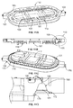
- Figure 5A depicts a perspective view of a mold tool 11 particularly adapted to providing sealant to a nutplate ring, for example a nutplate ring used in conjunction with an access opening of an airplane (e.g., an access opening of an airplane wing), and
- Figure 5B depicts an exploded perspective view of the mold tool 11. It may be noted that various aspects of the mold tool 11 discussed herein may be used in conjunction with other alternative sealing applications as well.
- the mold tool 11 includes a mold assembly 100, a vacuum assembly 200, an air control mount assembly 300, a frame 400, and an injection assembly 500.
- the mold assembly 100 provides a desired amount and positioning of sealant to a target location.
- the vacuum assembly 200 provides a vacuum during injection of sealant to help minimize or reduce air bubble formation in sealant during application.
- the air control mount assembly 300 provides control to the various components of the mold tool 11, and the injection assembly 500 may be utilized to deliver sealant to the mold assembly 100.
- each of the sub-assemblies are configured to work in conjunction with each other to provide injection molding, while still allowing for convenient assembly and disassembly for clean-up and/or maintenance.
- various of the sub-assemblies may be configured to allow assembly and disassembly without requiring disconnecting and reconnecting hoses or tubes.
- one or more sub-assemblies may be removed intact and separately cleaned, and subsequently reattached.
- Figure 6 provides an exploded perspective view of the mold assembly 100.
- the mold assembly 100 includes a mold body 102, mold volume seals 104, mold volume orifices 106, injection port inserts 108, a first air transfer plate 110, a second air transfer plate 120, a third air transfer plate 130, a lock assembly 140, lock assembly brackets 152, brackets 154, and a retaining ring 150.
- the mold body 102 may be understood as a primary component of the mold assembly 100.
- the mold body 102 may incorporate various aspects of the mold body 20 discussed herein.
- the mold body 102 may be composed of a clear material (e.g., acrylic). Use of a clear material allows the sealant injection process to be viewed.
- Figure 11A depicts a top perspective view of the mold body 102
- Figure 11B depicts a side sectional view of the mold body 102
- Figure 11C depicts a bottom perspective view of the mold body 102
- Figure 11D provides an enlarged view of a portion of Figure 11B .
- the mold assembly 100 includes a mold volume 101 defined with the mold body 102, as well as injection ports 103, injection port tabs 105, air transfer grooves 107, a vacuum channel 109, air transfer holes 111 separation piston pockets 113, lock cylinder pockets 115, and air transfer plate pockets 117.
- the mold volume 101 provides a volume into which sealant (e.g., sealant 42) is injected and formed about a target (e.g., nutplate member 60).
- sealant e.g., sealant 42
- the sealant 42 may fill the mold volume 101 from the injection ports 103.
- two injection ports 103 are proved at opposite ends of the mold body 102.
- the injection of the sealant 42 may be stopped and left to cure for predetermined amount of time.
- a vacuum applied within the mold volume 101 helps remove air or any voids during the injection process, and also may assist flow of the sealant 42.
- the mold volume 101 is designed to provide a minimum of 0.100" of sealant on each surface it protects (e.g., each surface of the nutplate member 60 and nutplates 62). As the mold body 102 is designed to be removed, angles within the mold volume 101 may be open and have polished surfaces to facilitate removal.
- Vacuum ports may be associated with the mold volume 101 and located at positions where air pockets may have an increased tendency to form, such as directly above the nutplates 62.
- the mold volume 101 may include a nut plate dome 180.
- a first orifice 192 may be disposed directly above the nut plate dome 180, with a set screw orifice 190 disposed above the first orifice 192.
- the first orifice 192 may have a diameter of about .020 inches, and the set screw orifice 190 may have a diameter of about .010 inches.
- a set screw orifice 190 may be employed due to the difficulty of forming a diameter as small as .010 inches or less in acrylic, which may be used for the mold body 102.
- a vacuum e.g., vacuum 52 depicted in Figure 1
- a vacuum channel 109 may be provided in fluid communication with the set screw orifices 190 to provide uniform or consistent application of the vacuum (e.g., vacuum 52 depicted in Figure 1 ).
- Use of the set screw orifices 190 in the illustrated embodiment helps inhibit or prevent flow of the sealant 42 upwards past the set screw orifice 190, thereby maintaining the vacuum (e.g., vacuum 52 depicted in Figure 1 ) for the desired length of time as well as simplifying clean-up after use of the mold tool 11.
- the vacuum e.g., vacuum 52 depicted in Figure 1
- the mold assembly 100 includes mold volume seals 104.
- the mold volume seals 104 include an inner seal 170 and an outer seal 172.
- the inner seal 170 and outer seal 172 may be o-ring seals that are placed in contact with a workpiece surface (e.g., surface 3 of workpiece 2) to create a seal for maintaining a vacuum (e.g., vacuum 52 depicted in Figure 1 ) within the mold volume 101.
- the outer seal 172 may be in contact with an inner surface of a wing panel (e.g., first surface 1702 depicted in Figure 17 ), and the inner seal 170 may be in contact with an access hole (e.g., opening 1704 depicted in Figure 17 ) associated with the nutplate member 60.
- a positive air pressure may be applied to the inner seal 170 and/or the outer seal 172 to urge the inner seal 170 and/or the outer seal 172 against the workpiece 2, helping to overcome any imperfections or differences (e.g., differences within manufacturing tolerances) between the mold tool 11 and the workpiece 2. It may be noted that a positive air pressure may similarly be applied to other seals (e.g., seals associated with the vacuum assembly 200).
- the nutplate dome 180 is a pocket formed within the mold volume 101 that surrounds a corresponding nutplate 62 of the nutplate member 60.
- the nutplate dome 180 may be sized and configured to provide at least 0.100 inches of sealant around the corresponding nutplate 62.
- the nutplate domes 180 may be positioned about the mold volume 101 to be centered about or aligned with the positions of the nutplates 62.
- the mold volume orifices 106 are configured to allow a vacuum (e.g., vacuum 52 depicted in Figure 1 ) to be provided within the mold volume 101 yet prevent, inhibit, or minimize the flow of the sealant 42 (due to the viscosity of the sealant 42) from entering aspects outside of the mold volume 101.
- a vacuum e.g., vacuum 52 depicted in Figure 1
- the injection ports 103 provide an opening for injection of the sealant 42 into the mold volume 101.
- a total of two injection ports 103 are provided on opposite sides of the mold body 102, so that the (injection assembly 500 (see Figures 5B and 10 ) only need to push sealant flow for half of the length of the mold body 102.
- the sealant 42 only needs to be pushed by the injection assembly 500 (see Figures 5B and 10 ) a distance of 23 inches. Reducing the distance the sealant 42 must be pushed reduces the effort required to push the sealant 42.
- a shop supply of air e.g., supply 70
- psi pounds per square inch
- the mold tool 11 also includes separation piston pockets 113, which are configured to accept separation pistons (e.g., separation pistons 205 as seen in Figure 7 ).
- the separation pistons 205, (or separation pistons 92 depicted in Figures 4A and 4B ) are configured to control access to the separation ports (e.g., separation ports 90, 54).
- pressurized air is introduced into the mold volume 101 (see, e.g., Figures 11B-11D ) and can help separate the mold body 102 (see, e.g., Figure 6 ) from the sealant 42 after the sealant 42 is cured.
- the separation ports 90 form part of a surface of the mold volume 101 (see, e.g., Figures 11B-11D ) forming the raised portions 69 (see, e.g., Figures 2 and 3 ) above the rivets 68 (see, e.g., Figures 2 and 3 ) via the concave tip 91.
- a relatively small air cylinder may overcome the surface adhesion and separate the separation pistons 92 from the sealant 42 to allow the pressurized air into the mold volume 101 (see, e.g., Figures 11B-11D ) to separate the mold body 102 from the cured sealant 42.
- the vacuum channel 109 is formed in the mold body 102.
- the vacuum channel 109 may be machined into the mold body 102 at a position corresponding to the location of the vacuum plate 208 (see Figure 7 ).
- the vacuum channel 109 is in fluid communication with the set screw orifices 190, and used to store and transfer a vacuum generated by the vacuum generators 202 (see Figure 7 ).
- the vacuum channel 109 may evenly distribute a vacuum generated by the vacuum generators 202 to the various nut plate domes 180 of the mold volume 101.
- the air control mount assembly 300 may include a control system (e.g., air control system 12) that utilizes an air-controlled logic to perform various functions discussed herein.
- Various air pathways may be designed into one or more of the various sub-assemblies (mold assembly 100, vacuum assembly 200, air control mount assembly 300, frame 400, and injection assembly 500) such that the one or more of the various sub-assemblies (mold assembly 100, vacuum assembly 200, air control mount assembly 300, frame 400, and injection assembly 500) may be conveniently detached from the mold tool 11.
- color coded tubing may be used, as well as pockets, holes, or other pathways machined into components of the mold tool 11.
- O-rings or other seals may be employed to seal passageways or paths for the air control system 12 to control aspects of the various sub-assemblies.
- air transfer plates first air transfer plate 110, second air transfer plate 120, and third air transfer plate 130
- the air transfer plates pocket 117 are disposed within the air transfer plates pocket 117 (see Figures 11B and 11C ), and used to control the flow of air among various subassemblies including the mold assembly 100.
- air-controlled logic is employed in the depicted embodiment, electronically controlled logic may be utilized alternatively or additionally in various embodiments.
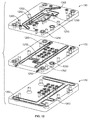
- Figure 12 depicts an exploded perspective view of the first air transfer plate 110, the second air transfer plate 120, and the third air transfer plate 130.
- the air transfer plates 110, 120, 130 include various holes 1200 and channels 1202.
- the holes 1200 pass through one or more plates and are used to transfer air from a source (e.g., supply 70) through a given plate to a target location.
- the depicted channels 1202 are machined into a surface of a given plate and used to distribute air to one or more components.
- the particular location and arrangement of holes 1200 and channels 1202 may be selected or designed for a particular application.
- the holes 1200 and channels 1202 are used as an alternative and/or supplement to hoses or piping for air transfer.
- air transfer plates 110, 120, 130 may simplify attachment and/or detachment of various components from the mold tool 11.
- channels 1202 of the air transfer plates 110, 120, 130 and/or other components of the mold tool 11 may be used to connect holes from different sub-assemblies that do not line up with each other.
- various holes 1200 may be drilled at angles to help change the direction of an air path to a desired location.
- the first air transfer plate 110 may be used to distribute air, for example to the vacuum generators 202 (see Figure 7 ).
- the second air transfer plate 120 may be used to transfer air, for example, for operating the separation pistons 205.
- the third air transfer plate 130 may be used to transfer air to the lock/unlock cylinders 142.
- the lock assembly brackets 152 are used to mount the lock assembly 140.
- the brackets 150 also help secure the lock assembly 140 in place, but also have associated air pathways 153 configured to provide pressurized air to the injection assembly 500 (See Figures 5B and 10 ).
- the mold body 102 may also include various features (e.g., vacuum channel 109, transfer holes 111) configured for the transfer of air between components and/or subassemblies of the mold tool 11.
- the vacuum channel 109 may be machined into the mold body 102 and used to connect holes from the vacuum plate 208 (see Figure 7 ) to the mold body 102 to provide air transfer to the vacuum generators 202.
- the separation air orifices 210 (which may be configured generally similar to orifices 96), may be disposed in holes through the mold body 102.
- the separation air orifices 210 may be configured as .020" set screw orifices to control the flow of air.
- separation air orifices 210 may provide for improved air flow (e.g., relative to air flow without use of the separation air orifices 210) to continue to separate the cured sealant 42 from the mold body 102 even after one or more surfaces have been separated, thus opening or losing air pressure.
- the lock assembly 400 includes lock cylinders 142 and tapered locks 144.
- lock cylinders 142 In the illustrated embodiment, a total of six lock cylinders 142, each having a tapered lock 144 disposed at an end, are shown.
- the lock cylinders 142 are configured to articulate the tapered locks 144.
- the lock cylinders 142 may be configured to be operated simultaneously.
- the lock cylinders 142 when activated, secure the mold tool 11 to the workpiece 2.
- Figure 13A depicts tapered locks 144 in an open or unlocked position 1302
- Figure 13B depicts tapered locks 144 in a closed or locked position 1304.
- the tapered locks 144 are positioned clear of, or to a side of, an access hole 1310, allowing the mold tool 11 to be inserted or removed from the access hole 1310.
- the tapered locks 144 are extended, with the sloped surface 1320 urging the mold tool 11 toward the workpiece 2 as the tapered locks 144 extend against the surface 1330 of a panel (e.g., lower wing panel of an aircraft) into which the access hole 1310 is formed.
- the tapered locks 144 may be configured to provide a wedging action urging the mold tool 11 against the workpiece as the tapered locks 144 are advance.
- the tapered locks 144 may be made of a plastic or other material configured to prevent damage to the workpiece 2.
- the lock cylinders 142 of the illustrated embodiment are double acting, utilizing air pressure to extend or retract.
- the interaction between the tapered locks 144 and the surface 1330 also helps to secure the mold tool 11 to the workpiece 2, allowing the mold tool 11 to travel with movement by the workpiece 2 and stay secured to the workpiece 2.
- the pressure in the lock cylinders 142 is applied during application of the vacuum in various embodiments, with the wedging action provided by the tapered locks 144 therefore provided as the vacuum further urges the mold tool 11 against the workpiece 2. Accordingly, the lock assembly 140 helps maintain the mold tool 11 in the position resulting from application of the vacuum.
- the mold body 102 includes lock cylinder pockets 115.
- the lock cylinder pockets 115 are machined into the mold body 102 and configured to accept the lock cylinders 142.
- the lock cylinder pockets 115 are configured so that a given lock cylinder 142 butts up against a corresponding lock cylinder 142, such that the reactive forces of the lock cylinder 142 acts in opposite directions against each other.
- the retaining ring 150 in the depicted embodiment provides a reactive force to counteract the forces on the tapered locks 144 to facilitate the locking of the tapered locks 144 to the workpiece 2.
- the mold body 102 also includes separation piston pockets 113.
- the separation piston pockets 113 are configured to house the separation pistons 205.
- the mold body 102 includes injection ports 103.
- the injection ports 103 are pockets machined into the mold body 102.
- the injection ports 103 are configured to accept injection port inserts 108 (see Figure 6 ).
- the injection port inserts 108 are configured to fit both the injection ports 103 as well as the tip of a sealant container to form a leak proof and air tight seal so that the sealant 42 may be introduced into the mold volume 101 without leaks.
- the injection port inserts 108 may also be configured to align the tip of a sealant container to injection the sealant 42 directly into the mold volume 101.
- the thumbscrews 160 are configured to secure the injection port inserts 108 in the injection ports 103.
- FIG. 7 provides an exploded perspective view of the vacuum assembly 200.
- the vacuum assembly 200 includes vacuum generators 202, separation cylinders 204 (provided with air by separation cylinder air lines 203), separation air lines 206, a vacuum plate 208, and separation pressurized air orifices 210.
- the vacuum assembly 200 is configured to generate the vacuum applied during injection of the sealant 42, and also houses at least a portion of the vacuum plumbing (e.g., hoses 201).
- the vacuum assembly also includes the separation cylinders 204 used to control the separation pistons 205, as well as the separation air lines 206 used to provide the separation air flow (e.g., separation pressure 56).
- the vacuum plate 208 may be made of acrylic and polished to facilitate viewing of the sealant 42 flowing in the mold volume 101.
- the vacuum generators 202 create the vacuum within the vacuum channel 109 that is applied to the mold volume 101 via the set screw orifices 190. In the illustrated embodiment, a total of eight vacuum generators 202 are employed. In some embodiments, the vacuum generators are configured to use air pressure and the Venturi Effect to create the vacuum used by the mold tool 11. The use of a number of vacuum generators 202 feeding one or more vacuum channels 109 allows for one or more vacuum generators 202 to lose effectiveness while still providing a desired or useful vacuum to the mold volume 101. Vacuum lines 207 may be utilized to place the vacuum generators 202 in fluid communication with the set screw orifices 190 via one or more vacuum channels 109. As discussed herein, application of a vacuum to the mold volume 101 helps pull out air bubbles and voids, as well as improving flow of the sealant 42 to help create a smoother filling of the mold volume 101.
- the vacuum assembly 200 may also be utilized to provide a separation air pressure 56 used to aid separation of the mold tool 11 from the cured sealant 42.
- the separation air pressure 56 may be used to separate cured sealant 42 from the exposed surfaces of the mold volume 101 making it possible to remove the mold tool 11 without tearing the cured sealant 42.
- standard shop air e.g., at between 90-100 psi
- the air e.g., from supply 70
- the separation pressurized air orifices 210 may be utilized to control the air flow to each separation piston pocket 113 (or other separation port 56), thereby allowing air from each separation piston pocket 113 to continue to push air against the sealant 42 even after an initial separation.
- FIG 8 provides an exploded perspective view of the air control mount assembly 300.
- the air control mount assembly 300 includes air control switches 302 (and corresponding air control buttons 303), air control tubing 304, toggle switch 306, brackets 308, air control solenoids 310, air control tubing 312, air control block mount 314 (including air connection 316 for connection with supply 70 (e.g., shop air supply)), handle mount boss 318 and mounting plate 320.
- air control switches 302 and corresponding air control buttons 303
- air control tubing 304 toggle switch 306, brackets 308, air control solenoids 310, air control tubing 312, air control block mount 314 (including air connection 316 for connection with supply 70 (e.g., shop air supply)), handle mount boss 318 and mounting plate 320.
- supply 70 e.g., shop air supply
- each solenoid 310a, 310b, 310c, 310d may be utilized in connection with one or more of the subassemblies to perform one or more of the processes disclosed herein (e.g., extend or retract lock cylinders 142, apply vacuum, injection sealant 42, or provide separation air, among others). Accordingly, in the illustrated embodiment, by depressing a given button, a corresponding solenoid acts to direct a desire air flow for performance of a corresponding task or process.
- the mounting plate 320 in the illustrated embodiment provides an interface between the mold body 102 and the frame 400.
- the mounting plate 320 is also used to mount the brackets 308, and the air control block mount 314. Air may be transferred through the mounting plate 320 to the mold body 102 and/or frame 400.
- the frame 400 may be mounted to the mounting plate 320 via openings 321 in the handle mount boss 318. Similar to the mold body 102, the mounting plate 320 may have various holes and/or channels provided therein to facilitate direction of air flows for the various processes described herein.
- the air control block mount 314 provides a platform for the solenoids 310 used to introduce air pressure into various components or aspects of the mold tool 11 to perform the tasks or processes discussed herein.
- the air supply 70 e.g., shop air
- the air supply 70 is coupled to the air control block mount 314 via the air connection 316, with the air control block mount 314 configured to deliver air from the supply 70 to the air control switches 302 and air control solenoids 310, and to feed pressurized air to the air control system 12.
- the solenoids 310 generally either supply pressurized air to a corresponding target location or close off the supply of air, thereby turning processes discussed herein “on” or “off.” It may be noted that, while the air control switches 302 are configured as spring return buttons 303, the toggle switch 306 is configured as a toggle to supply air pressure to the injection subassembly 500 instead of to a solenoid 310. When the toggle switch 306 is “on,” sealant 42 is injected into the mold volume 101, and when the toggle switch 305 is “off,” sealant 42 is not injected into the mold volume 101.
- Figure 9 provides an exploded perspective view of the frame 400.
- the frame 400 includes attach rails 402, handle rails 404, handle pads 406, air control tubing 407, flow control orifices 408, cylinder rails 410, cylinder rail claws 412, pushing cylinders 414, and piston pads 416.
- the frame 400 provides for handling of the mold tool 11 and for the force necessary to pull the tool 11 from the workpiece 2 after the sealant 42 has cured.
- the pushing cylinders 414 are configured to extend to urge the mold tool 11 away from the workpiece 2, facilitating the removal of the mold tool 11 from the workpiece 2.
- the attach rails 402, handle rails 404, cylinder rails 410, and cylinder rail claws 412 may be bolted and/or doweled together, and are used to transfer forces created by the pushing action of the pushing cylinders 414 against the workpiece.
- the attach rails 402 may be utilized to attached the frame assembly 400 to the handle mount boss 318. Additionally, the attach rails 402 may have channels and/or holes (e.g., generally similar to holes 1200 and channels 1202) therethrough, which cooperate with the air control tubing 407 for the provision of air to the pushing cylinders 414.
- the handle rails 404 attach between the cylinder rails 410. In the illustrated embodiment, the handle rails 404 provide for mounting of the handle pads 406, and also add stiffness to the frame assembly 400. The handle pads 406 help facilitate the manipulation of the frame assembly 400 by an operator.
- the cylinder rails 410 provide for the attachment of the pushing cylinders 414 to the frame assembly 400, and serve to transfer force generated by the pushing cylinders 414 to the attach rails 402.
- the cylinder rail claws 412 may be machined end pieces to the cylinder rails 410.
- the cylinder rail end claws may be press fit and doweled into position.
- the cylinder rail claws 412 are configured to mount the pushing cylinders 414 to the frame assembly 400.
- the pushing cylinders 414 create force to urge the mold tool 11 from the workpiece 2 and cured sealant 42.
- the pushing cylinders may generate about 1250 pounds of force. The force generated will be dependent on the pressure provided from the supply 70.
- the pushing cylinders 414 are flow controlled to create force slowly and smoothly.
- the piston pads 416 are attached to ends of the pushing cylinders 414. The piston pads 414 contact the surface 3 of the workpiece 2 and may be made of a plastic or other material to avoid scratching the workpiece 2.
- Figure 10 provides an exploded perspective view of the injection assembly 500.
- the injection assembly 500 includes a sealant dispenser 501 that includes a pressure cap assembly (including a tightening knob 504), a sliding bracket assembly 506 (including springs 508), a mounting frame 510 (including a vertical slide guide rail 512), a metal sleeve 514, and a sealant cartridge 516 having a cartridge tip 518.
- a sealant dispenser 501 is shown in Figure 10 ; however, two or more sealant dispensers 501 (e.g., disposed on opposite sides of a mold body 102) may be utilized in various embodiments.
- the sealant dispenser 501 is configured to hold the sealant cartridge 516 in a desired orientation in an airtight fixture.
- the sealant dispenser 501 is also configured to apply the necessary force on the cartridge tip 518 to form an air tight seal in the injection port inserts 108, allowing the mold tool 11 to apply air pressure to one or more sealant cartridges 516 to feed the sealant 42 into the mold volume 101.
- the sealant dispensers 501 may be turned off, but the sealant cartridges 516 left in place until curing is complete.
- the sealant cartridges 516 may then be removed from the mold tool 11 after the mold tool 11 is removed from the workpiece 2. It may be noted that, in various embodiments, the sealant 42 may be disposed manually using handheld sealant dispensers.
- the sealant dispenser 501 may be prepared for use by unscrewing the tightening knob 504 and tilting the pressure cap assembly 502 out of the way. Then, a sealant cartridge 516 is slid into the metal sleeve 514. Next, the pressure cap assembly 502 is tilted back over the sealant cartridge 516, and the tightening knob 504 tightened to form an air tight seal between the pressure cap assembly 502 and the sealant cartridge 516.
- the mounting frame 510 attaches the sealant dispenser 501 to the mold body 102.
- the vertical slide guide rail 512 is configured to act as a sliding rail for the sliding bracket assembly 506.
- the mounting frame 510 may be made of aluminum.
- the sliding bracket assembly 506 slides up and down the mounting frame, and may be made of a plastic to provide efficient sliding against the vertical slide guide rail 512.
- the metal sleeve 514 may be positioned and held into place so that when a prepared sealant cartridge 516 is inserted, the springs 508 provide sufficient force to create a seal between the sealant cartridge tip 518 and the injection port insert 108.
- the metal sleeve 514 is configured to hold the sealant cartridge 516, and provides an opposing force for the pressure cap assembly 502 to seal the sealant cartridge 516 in place.
- the springs 508 apply a force between the mounting frame 510 and the sliding bracket assembly 506 to urge the sealant cartridge tip 518 against the injection port 103, thereby creating a seal between the sealant cartridge tip 518 and the injection port insert 108.
- the pressure cap assembly 502 acts to hold the sealant cartridge 516 in the metal sleeve 514. When tightened, the pressure cap assembly 502 forms an airtight seal between the sealant cartridge 516 and the pressure cap assembly 502, making it possible to introduce air pressure through into the sealant cartridge 516 to push the sealant 42 into the mold volume 101. When the air pressure is stopped and released from the sealant cartridge 42, the sealant 42 stops flowing into the mold volume 101.
- the air pressure may be provided via the tubing 505, which may be provided with air pressure under the control of the toggle switch 306.
- the sealant cartridge 516 may be a standard 6 inch sealant cartridge used for production sealants commonly used in the aerospace industry.
- the sealant cartridge 516 may be stored at -40 degrees Fahrenheit.
- the sealant 42 may be used at about 70 degrees Fahrenheit.
- the cartridge tip 518 may be a standard, straight 2 inch tip made for the sealant cartridge 516.
- the tip 518 may have an orifice of about 1/8" through which the sealant 42 is fed. It may be noted that because use of the mold tool 11 provides for faster and more accurate placement of the sealant 42, the sealant 42 may have a shorter time to solidify and/or cure than sealants used with conventional manual sealing approaches.
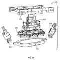
- Figure 14 provides an exploded perspective view of a mold tool 1400 configured for placement by a robot 1500
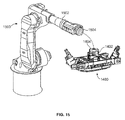
- Figure 15 depicts a perspective view of the robot 1500 and the mold tool 1400.
- the mold tool 1400 includes a mold assembly 100, a vacuum assembly 200, a mounting assembly 1402, a frame 400, and an injection assembly 500.
- the mold assembly 100, vacuum assembly 200, frame 400, and injection assembly 500 may be generally similar to the similar named and numbered components discussed above in connection with the embodiment depicted in Figure 5 .
- the mounting assembly 1402 may be generally similar with the air control assembly 300 in certain respects; however the mounting assembly 1402 is configured for use with a robotic arm 1502 of the robot 1500 (see Figure 15 ) as part of an automated process.
- the mounting assembly 1402 includes a quick disconnect 1404 configured for mounting to a robotic arm.
- the mounting assembly 1402 is also configured to receive pressurized air from the supply 70 via the robotic arm 1502.
- a mold tool 1400 including a mounting assembly 1402 configured for use with a robot 1500 enables use of the mold tool 1400 as part of a fully automated process.
- the robot 1500 may place the mold tool 1400 into a desired position and also activate the various processes or tasks performed by the mold tool 1400 discussed herein.
- the robot 1500 includes a robotic arm 1502.
- the robot 1500 may be configured as a standard 6 axis robot.
- the robot 1500 includes a quick disconnect 1504 at the free end of the robotic arm 1502.
- the quick disconnect 1504 of the robot cooperates with the quick disconnect 1404 of the mounting assembly 1402 to attach and detach the mold tool 1400 to the robot 1500.
- the quick disconnect 1404 of the mounting assembly 1402 may also be configured to mate with or accept pressurized air from the air supply 70 when not mounted to the robot 1500, for example to provide operation of one or more aspects of the mold tool 1400 when the mold tool 1400 is disconnected from the robot 1500, for example when traveling with the workpiece 2.
- Figure 16 provides a flowchart of a method 1600 for providing sealing to a workpiece using a mold tool, in accordance with various embodiments.
- the method 1600 may employ or be performed by structures or aspects of various embodiments (e.g., systems and/or methods and/or process flows) discussed herein.
- certain steps may be omitted or added, certain steps may be combined, certain steps may be performed concurrently, certain steps may be split into multiple steps, certain steps may be performed in a different order, or certain steps or series of steps may be re-performed in an iterative fashion.
- a mold tool (e.g., mold tool 10, mold tool 11, mold tool 1400) is mounted to a target workpiece (e.g., workpiece 2).
- the mold tool 11 may be positioned proximate the workpiece 2 as shown in Figure 17 .
- the workpiece 2 is configured as a wing 1700 having a first surface 1702 with an opening 1704 extending through the wing 1700.
- the opening 1704 is surrounded by a nutplate ring 1706 which the mold tool 11 will be used to seal.
- the mold tool 11 is advanced into the opening 1704 of the workpiece 2. Then, at 1608, the mold tool 11 is secured to the workpiece 2.
- the mold tool 11 may be secured to the workpiece 2 via a lock assembly 140 including tapered locks 144, with the lock assembly 140 controlled by an air control system 12.
- an operator may depress a button (or a robot may actuate a system) to cause the air control system 12 to direct a positive air pressure to extend lock cylinders 142 of the lock assembly.
- the tapered locks 144 may extend past the opening 1704 to engage a second surface 1708 (the second surface 1708 is opposite the first surface 1702) to secure the mold tool 11 to the workpiece 2.
- a vacuum is applied to a mold volume (e.g., mold volume 101) of the mold tool 11.
- the vacuum may be applied via vacuum application ports and under control of the air control system 12.
- the mold volume may include sub-volumes (e.g., nutplate domes) configured to provide sealant around nutplates of the nutplate ring 1706.
- Application of the vacuum improves sealant flow and reduces air bubble or void formation in various embodiments.
- sealant e.g., sealant 42
- sealant may be injected into sub-volumes of the mold volume via sealant injection ports to cover features (e.g., nutplates, rivets, or the like) with the sealant.
- the sealant flow may be improved under the influence of the vacuum (which may help draw the sealant through the mold volume), and air bubble formation may be prevented or impeded due to the influence of the vacuum.
- the sealant may be provided to the sub-volumes via a mold channel.
- the sealant in some embodiments may be injected from one or more sealant cartridges that have been pre-loaded onto the mold tool 11 before the mold tool 11 is secured to the workpiece 2.
- the sealant may be injected, for example, until a desired amount of sealant has been introduced into the mold.
- at least a portion of the mold tool 11 may be clear (e.g., transparent or translucent) to allow a visual determination of when a desired amount of sealant has been injected.
- sealant may be injected for a short time (e.g., three seconds) after opposing sealant flows are observed to meet and meld together, to provide a back pressure for improving the meld while preventing overfilling that may cause sealant to bleed through one or more portions of the mold tool 11.
- the sealant that has been injected into the sub-volumes is drawn from a higher pressure zone (e.g., portions of the sub-volumes proximate the mold channel) to a lower pressure zone (e.g., portions of the sub-volumes proximate the vacuum application ports.
- the vacuum may be turned off, after the sealant injection has stopped.
- the sealant is cured.
- the mold tool 11 may be left secured to the workpiece 2 overnight or for another predetermined time period to allow the sealant 42 to cure.
- the sealant may be heated to shorten the time for curing.
- a cover may be placed over the mold tool 11 and the air surrounding the mold tool 11 heated in order to heat the mold tool 11 (and the sealant 42 inside the mold tool 11).
- the air supply 70 may be disconnected from the mold tool 11 after the sealant has solidified and re-attached for the removal process.
- the mold tool 11 is removed from the workpiece 2.
- the mold tool 11 is unlocked from the work piece (e.g., the tapered locks 144 are retracted).
- a separation pressure may be applied to the sealant 42 via at least one separation port 54.
- the separation pressure may provide an air film between the sealant 42 and the mold volume to initiate separation.
- a pushing force urges the mold tool 11 away from the workpiece. The pushing force may be applied, for example, by pushing pistons 414.
- the mold tool 11 may be disassembled for cleaning. For example, any remaining sealant may be removed from the mold volume, and any sealant that entered vacuum application ports and/or separation ports may be removed. Once cleaned, the mold tool 11 may be re-assembled and used for a subsequent sealing process.
- illustrative method 1900 may include specification and design (block 1904) of aircraft 1902 and material procurement (block 1906).
- component and subassembly manufacturing (block 1908) and system integration (block 1910) of aircraft 1902 may take place.
- aircraft 1902 may go through certification and delivery (block 1912) to be placed in service (block 1914).
- aircraft 1902 may be scheduled for routine maintenance and service (block 1916).
- Routine maintenance and service may include modification, reconfiguration, refurbishment, etc. of one or more systems of aircraft 1902.
- examples of the present disclosure may be used in conjunction with one or more of blocks 1908, 1910, or 1916.
- Each of the processes of illustrative method 1900 may be performed or carried out by a system integrator, a third party, and/or an operator (e.g., a customer).
- a system integrator may include, without limitation, any number of aircraft manufacturers and major-system subcontractors
- a third party may include, without limitation, any number of vendors, subcontractors, and suppliers
- an operator may be an airline, leasing company, military entity, service organization, and so on.
- aircraft 1902 produced by illustrative method 1900 may include airframe 1918 with a plurality of high-level systems 1920 and interior 1922.
- high-level systems 1920 include one or more of propulsion system 1924, electrical system 1926, hydraulic system 1928, and environmental system 1930. Any number of other systems may be included.
- propulsion system 1924 one or more of propulsion system 1924
- electrical system 1926 electrical system 1926
- hydraulic system 1928 any number of other systems may be included.
- an aerospace example is shown, the principles disclosed herein may be applied to other industries, such as the automotive industry. Accordingly, in addition to aircraft 1902, the principles disclosed herein may apply to other vehicles, e.g., land vehicles, marine vehicles, space vehicles, etc.
- examples of the present disclosure may be used in conjunction with one or more of airframe 1918 or interior 1922.
- Apparatus(es) and method(s) shown or described herein may be employed during any one or more of the stages of the manufacturing and service method 1900.
- components or subassemblies corresponding to component and subassembly manufacturing 1908 may be fabricated or manufactured in a manner similar to components or subassemblies produced while aircraft 1902 is in service.
- one or more examples of the apparatus(es), method(s), or combination thereof may be utilized during production stages 1908 and 1910, for example, by substantially expediting assembly of or reducing the cost of aircraft 1902.
- one or more examples of the apparatus or method realizations, or a combination thereof may be utilized, for example and without limitation, while aircraft 1902 is in service, e.g., maintenance and service stage (block 1916).
- a structure, limitation, or element that is "configured to” perform a task or operation is particularly structurally formed, constructed, or adapted in a manner corresponding to the task or operation.
- an object that is merely capable of being modified to perform the task or operation is not “configured to” perform the task or operation as used herein.
Landscapes
- Engineering & Computer Science (AREA)
- Manufacturing & Machinery (AREA)
- Mechanical Engineering (AREA)
- Transportation (AREA)
- Aviation & Aerospace Engineering (AREA)
- Moulds For Moulding Plastics Or The Like (AREA)
- Casting Or Compression Moulding Of Plastics Or The Like (AREA)
Abstract
Description
- Embodiments of the present disclosure generally relate to systems and methods for sealant injection molding.
- Various structures to be sealed may have fasteners or other features that are to be sealed. For example, a nutplate ring of an access hole of an airplane wing may be sealed. However, conventional approaches to sealing such structures rely on manual application of sealant. Manual application of sealant may provide an undesired amount of sealant, and/or require an undesired amount of time for application of sealant and subsequent trimming or removal of excess sealant.
- Accordingly, reduction of time and/or expense of sealing structures, (such as access ports of airplane wings, are provided in various embodiments disclosed herein. It may be noted that in various embodiments, one or more aspects of the presently disclosed subject matter may be utilized in conjunction with the sealing of other structures or fastener configurations than the illustrated examples of access port nut plates.
- Certain embodiments of the present disclosure provide a mold tool that includes plural mold sub-volumes configured to receive a sealant, a mold channel in fluid communication with the mold sub-volumes, a sealant injection port in fluid communication with the mold channel, vacuum application ports in fluid communication with the mold sub-volumes, and an air control system. The air control system is operably coupled to the mold sub-volumes and the mold channel, and is configured to apply a vacuum to the mold sub-volumes via the vacuum application ports.
- Certain embodiments of the present disclosure provide a mold tool for providing sealant to features of a target workpiece. The mold tool includes a frame, a mold body, an air control system, and a vacuum assembly. The mold body is coupled to the frame, and defines a mold volume configured to receive the sealant. The mold volume includes plural mold sub-volumes, and a mold channel. The mold body includes a sealant injection port in fluid communication with the mold volume, and vacuum application ports in fluid communication with the mold sub-volumes. The air control system is operably coupled to the mold body, and is configured to apply a vacuum to mold volume via the vacuum application ports. The vacuum assembly is operably coupled to the mold body and the air control system. The vacuum assembly includes a vacuum plate and vacuum generators mounted on the vacuum plate. The vacuum generators are configured to apply the vacuum to the mold volume under control of the air control system.
- Certain embodiments of the present disclosure provide a method. The method includes injection sealant into a number of mold sub-volumes disposed over corresponding features of an object to be sealed. The method also includes drawing the sealant from a higher pressure zone into a lower pressure zone in at least one of the sub-volumes to cover at least one of the features.
-
-
Figure 1 illustrates a schematic side sectional view diagram of a mold tool, according to an embodiment of the present disclosure. -
Figure 2 is a perspective view of a sealing member formed with a mold tool, according to an embodiment of the present disclosure. -
Figure 3 is a perspective view of a nutplate member to be sealed by the sealing member ofFigure 2 . -
Figure 4A depicts a side schematic view of a separation port assembly in a closed position, according to an embodiment of the present disclosure. -
Figure 4B depicts the separation port assembly ofFigure 4A in an open position. -
Figure 5A depicts a perspective view of a mold tool adapted to providing sealant to a nutplate ring, according to an embodiment of the present disclosure. -
Figure 5B depicts an exploded perspective view of the mold tool ofFigure 5A . -
Figure 6 provides an exploded perspective view of a mold assembly, according to an embodiment of the present disclosure. -
Figure 7 provides an exploded perspective view of a vacuum assembly, according to an embodiment of the present disclosure. -
Figure 8 provides an exploded perspective view of an air control mount assembly, according to an embodiment of the present disclosure. -
Figure 9 provides an exploded perspective view of a frame, according to an embodiment of the present disclosure. -
Figure 10 provides an exploded perspective view of an injection assembly, according to an embodiment of the present disclosure. -
Figure 11A depicts a top perspective view of a mold body, according to an embodiment of the present disclosure. -
Figure 11B depicts a side sectional view of the mold body ofFigure 11A . -
Figure 11C depicts a bottom perspective view of the mold body ofFigure 11A . -
Figure 11D provides an enlarged view of a portion ofFigure 11B . -
Figure 12 is a perspective view of air transfer plates, according to an embodiment of the present disclosure. -
Figure 13A depictstapered locks 144 in an open position, according to an embodiment of the present disclosure. -
Figure 13B depicts the tapered locks ofFigure 13A in a closed position. -
Figure 14 provides an exploded perspective view of a mold tool, according to an embodiment of the present disclosure. -
Figure 15 depicts a perspective view of a robot and mold tool, according to an embodiment of the present disclosure. -
Figure 16 is a flowchart of a method, according to an embodiment of the present disclosure. -
Figure 17 depicts a mold tool being positioned proximate a workpiece. -
Figure 18 depicts tapered locks securing a mold tool to a workpiece. -
Figure 19 is a block diagram of aircraft production and service methodology. -
Figure 20 is a schematic illustration of an aircraft. - The foregoing summary, as well as the following detailed description of certain embodiments will be better understood when read in conjunction with the appended drawings. As used herein, an element or step recited in the singular and preceded by the word "a" or "an" should be understood as not necessarily excluding the plural of the elements or steps. Further, references to "one embodiment" are not intended to be interpreted as excluding the existence of additional embodiments that also incorporate the recited features. Moreover, unless explicitly stated to the contrary, embodiments "comprising" or "having" an element or a plurality of elements having a particular property may include additional elements not having that property.
- Embodiments of the present disclosure provide systems and methods for sealing using a sealant application mold. Various embodiments eliminate the use for manual application of sealant, reduce the time for applying sealant, and improve quality. In various embodiments, a sealant injection system (e.g.,
mold tool - Embodiments of the present disclosure provide improved sealing. Reduction of time and/or improvement in quality are accordingly provided as discussed herein.
-
Figure 1 illustrates a schematic side sectional view of amold tool 10, according to an embodiment of the present disclosure. Themold tool 10 is configured to providesealant 42 to features 4 (e.g., to a volume surrounding features 4) of atarget workpiece 2. Thefeatures 4 are examples of objects to be sealed. As seen in the illustrated embodiment, thetarget workpiece 2 has a surface 3 to which themold tool 10 is secured or otherwise engages. As shown inFigure 1 , thefeatures 4 extend from the surface 3. Thetarget workpiece 2, for example, may have a nutplate ring, and thefeatures 4 may be nutplates, as discussed in more detail elsewhere herein. As seen inFigure 1 , the depictedmold tool 10 includes amold body 20 and anair control system 12. Themold body 20 is generally configured for delivery of thesealant 42 to thefeatures 4 and/or other portions of theworkpiece 2 and maintenance of thesealant 42 around thefeatures 4 and/or other portions of theworkpiece 2 during curing of thesealant 42. Theair control system 12 receives air from a supply 70 (e.g., a shop supply of pressurized air), and directs air to various components of themold tool 10 at appropriate times during a sealing process. It may be noted that the particular numbers, sizes, shapes, and/or relationships between aspects or components depicted inFigure 1 are provided by way of example, and that various alternative numbers, types, sizes, shapes, and/or arrangements may be employed in other embodiments. - The depicted
mold body 20 defines amold volume 30. Themold volume 30 is configured to receive thesealant 42. Themold volume 30 of the illustrated embodiment includesmold sub-volumes 32 and amold channel 34. Each of the depictedmold sub-volumes 32 is disposed in a predetermined position corresponding to the location of acorresponding feature 4 when themold tool 10 is secured in a desired position to theworkpiece 2. The size and shape of themold sub-volumes 32 are configured to provide a desired amount ofsealant 42 around thefeatures 4. The shape ofmold sub-volumes 32 may generally correspond to the shape of thefeatures 4, but need not be identically shaped.. The mold sub-volumes 32 are sized to be large enough to allow a desired amount ofsealant 42 to cover thefeatures 4. Thechannel 34 connects thevarious mold sub-volumes 32 and provides a passageway for thesealant 42 to reach themold sub-volumes 32. - As also seen in
Figure 1 , the depictedmold body 20 also includes a sealant injection port 40 (the depicted example includes two sealant injection ports 40). Thesealant injection port 40 is in fluid communication with themold volume 30. Generally, thesealant injection port 40 is configured to provide entry of thesealant 42 into themold volume 30. Themold tool 10, and themold sub-volumes 32 help to accurately and reliably provide a desired amount of sealant to target features (e.g., features 4) of theworkpiece 2, while eliminating or reducing anyexcess sealant 42 that may need to be trimmed away after a sealing process. Themold tool 10 also helps maintain thesealant 42 in a desired position and/or shape during curing of thesealant 42. - Further, the depicted
mold body 10 includesvacuum application ports 50 in fluid communication with the mold sub-volumes. In some embodiments, thevacuum application ports 50 may be in fluid communication with each other, for example via a vacuum channel (e.g.,vacuum channel 109 depicted inFigures 11A, 11B, and 11D ) as discussed elsewhere herein. In the illustrated embodiment, eachvacuum application port 50 is disposed above a correspondingmold sub-volume 32, and configured to apply avacuum 52 to the correspondingmold sub-volume 32, under the direction of thecontrol system 12, during the injection of thesealant 42. Thevacuum 52 applied via thevacuum application ports 50, for example, helps to eliminate or reduce the formation of air bubbles during a sealing process, and also may help to draw themold tool 10 to theworkpiece 2 during use. Thevacuum 52 may also help remove volatiles or gases from themold volume 30. - The
air control system 12 is operably coupled to themold body 20, and is configured to apply avacuum 52 to thevacuum application ports 50. As used herein, a vacuum may refer to a reduced pressure that draws material away from a volume to which the vacuum is placed in fluid communication. It may be noted that the strength of the vacuum and/or the size of thevacuum application ports 50 may be selected to prevent inhibit thesealant 42 from passing through thevacuum application ports 50. For example, the size at least a portion of thevacuum application ports 50 may be sized such that the viscosity of thesealant 42 prevents passage of thesealant 42 completely through the vacuum application ports 50 (although, in some embodiments, a nominal amount of sealant may enter thevacuum application ports 50. - With reference to
Figures 2 and 3 , in some embodiments, theworkpiece 2 may be a nut plate member 60 (e.g., a ring-shaped member configured to be disposed around an access hole of a wing of an airplane) havingplural nut plates 62 disposed around thenut plate member 60. The mold sub-volumes 32 may be configured as nut plate domes 33 (seeFigure 1 ), with the nut plate domes 33 sized and configured to be positioned overcorresponding nut plates 62 when themold tool 10 is in position to seal thenut plate member 60. With thesealant 42 cured, and themold tool 10 removed a sealing member 65 (seeFigure 2 ) may be provided and left in place over thenut plate member 60. - As seen in
Figure 2 , the sealingmember 65 comprises raised portions 66 (formed by and corresponding to the mold sub-volumes 32) and flat portions 67 (formed by and corresponding to the mold channel 34). Theflat portions 67 may also help provide sealant around rivets 68 used to secure thenut plate member 60 in place. Themold tool 11 may also be configured to provide raisedportions 69 over therivets 68. - In the embodiment depicted in
Figure 1 , themold tool 10 also includesseparation ports 54 that are in fluid communication with themold volume 30. Theair control system 12 is configured to apply aseparation pressure 56 to thesealant 42 via theseparation ports 54. For example, theair control system 12 may direct a positive pressure from theair supply 70 to themold volume 30 via theseparation ports 54. Theseparation pressure 56 provided via theseparation ports 54 may be applied after thesealant 42 has cured, and used to help separate curedsealant 42 from themold body 20, and/or provide a film of air between curedsealant 42 and themold body 20, facilitating removal of themold tool 10 from theworkpiece 2 after thesealant 42 has cured. - In some embodiments, the
mold tool 10 may also includeseparation pistons 57 associated with theseparation ports 56, with theair control system 12 configured to switch theseparation ports 56 between open and closed positions with theseparation pistons 57. For example, in one position, theseparation pistons 57 may prevent the flow of air under positive pressure to themold volume 20 via the separation ports 56 (e.g., during injection and curing of sealant), while in another position theseparation pistons 57 may allow the flow of air under positive pressure to themold volume 20 via theseparation ports 56. -
Figure 4A depicts a side schematic view of aseparation port assembly 80 in aclosed position 82, andFigure 4B depicts a side schematic view of theseparation port assembly 80 in anopen position 84. As seen inFigures 4A and 4B , theseparation port assembly 80 includes aseparation port 90 with aseparation piston 92 disposed therein. Theseparation port assembly 80 also includes anair transfer hole 94. An orifice 96 (e.g., a .020" set screw orifice) is provided in the illustrated embodiment to provide a desired air flow through theair transfer hole 94. An upper O-ring 98 and a lower O-ring 99 are provided to help seal theseparation port 90. Theseparation port 90 includesrelease ports 91 for providing a controlled flow of air to an associated mold volume (e.g., mold volume 30). Theseparation piston 92 of the illustrated embodiment includes aconcave tip 93. When in theclosed position 82, theseparation piston 92 blocks flow of air fromair transfer hole 94 to and through theseparation port 90. When in theopen position 84, theseparation piston 92 allows the flow of air fromair transfer hole 94 to and through theseparation port 90. The position of theseparation piston 92 may be controlled, for example, by an air control system such asair control system 12. Theconcave tip 93 may be configured to position sealant to provide raisedportions 69 disposed aboverivets 68. - With continued reference to
Figure 1 , in the illustrated embodiment thevacuum application ports 50 includeorifices 51. Theorifices 51 are sized and configured to prevent or inhibit the flow ofsealant 42 upward through thevacuum application ports 51. In the illustrated embodiment, theorifices 51 have adiameter 53 that is sized and configured to inhibit the flow ofsealant 42 through theorifices 51. For example, in some embodiments, the diameter may be .010 inch or less. The size and the shape of theorifices 51 may vary in different embodiments, for example depending on the viscosity of thesealant 42. For instance, a smaller diameter may be employed with less viscous sealants, and a larger diameter may be employed with more viscous sealants. While the particular size of diameter may vary for different applications (e.g., different diameters may be used for different sealants), it may be noted that a properly sized diameter prevents a large quantity of sealant from being drawn away from the sub-volumes and unused, or from being drawn past the vacuum application ports and into an interior of the mold tool. The sealant injection passages in the device have a known volume and the volume of the final cured sealant on the nutplate has a known value which allows control of a known amount of sealant for every sealant operation to minimize or reduce waste. - In various embodiments, the
mold body 20 may be made of a translucent or transparent material. Accordingly, an operator may be able to view the amount ofsealant 42 inside themold volume 30 and stop addition ofsealant 42 after a desired amount ofsealant 42 is observed in themold volume 30. - As discussed in connection with
Figure 1 , themold tool 10 may be used to provide sealant to anutplate member 60.Figure 5A depicts a perspective view of amold tool 11 particularly adapted to providing sealant to a nutplate ring, for example a nutplate ring used in conjunction with an access opening of an airplane (e.g., an access opening of an airplane wing), andFigure 5B depicts an exploded perspective view of themold tool 11. It may be noted that various aspects of themold tool 11 discussed herein may be used in conjunction with other alternative sealing applications as well. - As seen in
Figures 5A and 5B , themold tool 11 includes amold assembly 100, avacuum assembly 200, an aircontrol mount assembly 300, aframe 400, and aninjection assembly 500. Generally, themold assembly 100 provides a desired amount and positioning of sealant to a target location. Thevacuum assembly 200 provides a vacuum during injection of sealant to help minimize or reduce air bubble formation in sealant during application. The aircontrol mount assembly 300 provides control to the various components of themold tool 11, and theinjection assembly 500 may be utilized to deliver sealant to themold assembly 100. - In the illustrated embodiment, each of the sub-assemblies (
mold assembly 100,vacuum assembly 200, aircontrol mount assembly 300,frame 400, and injection assembly 500) are configured to work in conjunction with each other to provide injection molding, while still allowing for convenient assembly and disassembly for clean-up and/or maintenance. For example, various of the sub-assemblies may be configured to allow assembly and disassembly without requiring disconnecting and reconnecting hoses or tubes. In some embodiment, one or more sub-assemblies (mold assembly 100,vacuum assembly 200, aircontrol mount assembly 300,frame 400, and injection assembly 500) may be removed intact and separately cleaned, and subsequently reattached. -
Figure 6 provides an exploded perspective view of themold assembly 100. As seen inFigure 6 , themold assembly 100 includes amold body 102, mold volume seals 104,mold volume orifices 106, injection port inserts 108, a firstair transfer plate 110, a secondair transfer plate 120, a thirdair transfer plate 130, alock assembly 140, lockassembly brackets 152,brackets 154, and a retainingring 150. - The
mold body 102 may be understood as a primary component of themold assembly 100. Themold body 102, for example, may incorporate various aspects of themold body 20 discussed herein. For example, themold body 102 may be composed of a clear material (e.g., acrylic). Use of a clear material allows the sealant injection process to be viewed.Figure 11A depicts a top perspective view of themold body 102,Figure 11B depicts a side sectional view of themold body 102,Figure 11C depicts a bottom perspective view of themold body 102, andFigure 11D provides an enlarged view of a portion ofFigure 11B . As seen inFigures 11A-11D , themold assembly 100 includes amold volume 101 defined with themold body 102, as well asinjection ports 103,injection port tabs 105, air transfer grooves 107, avacuum channel 109, air transfer holes 111 separation piston pockets 113, lock cylinder pockets 115, and air transfer plate pockets 117. - Generally, the
mold volume 101 provides a volume into which sealant (e.g., sealant 42) is injected and formed about a target (e.g., nutplate member 60). Thesealant 42 may fill themold volume 101 from theinjection ports 103. In the illustrated embodiment, twoinjection ports 103 are proved at opposite ends of themold body 102. When the flow ofsealant 42 from theinjection ports 103 meet and melt together, the injection of thesealant 42 may be stopped and left to cure for predetermined amount of time. As discussed herein, a vacuum applied within themold volume 101 helps remove air or any voids during the injection process, and also may assist flow of thesealant 42. In the depicted embodiment, themold volume 101 is designed to provide a minimum of 0.100" of sealant on each surface it protects (e.g., each surface of the nutplatemember 60 and nutplates 62). As themold body 102 is designed to be removed, angles within themold volume 101 may be open and have polished surfaces to facilitate removal. - Vacuum ports (e.g., vacuum application ports 50) may be associated with the
mold volume 101 and located at positions where air pockets may have an increased tendency to form, such as directly above thenutplates 62. For example, as best seen inFigure 11D , themold volume 101 may include anut plate dome 180. Afirst orifice 192 may be disposed directly above thenut plate dome 180, with aset screw orifice 190 disposed above thefirst orifice 192. Thefirst orifice 192 may have a diameter of about .020 inches, and theset screw orifice 190 may have a diameter of about .010 inches. Aset screw orifice 190 may be employed due to the difficulty of forming a diameter as small as .010 inches or less in acrylic, which may be used for themold body 102. A vacuum (e.g.,vacuum 52 depicted inFigure 1 ) may be applied to themold volume 101 via a series of setscrew orifices 190 in fluid communication with corresponding nut plate domes 180 of themold volume 101. Further, avacuum channel 109 may be provided in fluid communication with the setscrew orifices 190 to provide uniform or consistent application of the vacuum (e.g.,vacuum 52 depicted inFigure 1 ). Use of the setscrew orifices 190 in the illustrated embodiment helps inhibit or prevent flow of thesealant 42 upwards past theset screw orifice 190, thereby maintaining the vacuum (e.g.,vacuum 52 depicted inFigure 1 ) for the desired length of time as well as simplifying clean-up after use of themold tool 11. - As best seen in
Figures 11C and 11D , themold assembly 100 includes mold volume seals 104. In the illustrated embodiment themold volume seals 104 include aninner seal 170 and anouter seal 172. Theinner seal 170 andouter seal 172, for example, may be o-ring seals that are placed in contact with a workpiece surface (e.g., surface 3 of workpiece 2) to create a seal for maintaining a vacuum (e.g.,vacuum 52 depicted inFigure 1 ) within themold volume 101. For example, theouter seal 172 may be in contact with an inner surface of a wing panel (e.g.,first surface 1702 depicted inFigure 17 ), and theinner seal 170 may be in contact with an access hole (e.g., opening 1704 depicted inFigure 17 ) associated with thenutplate member 60. In various embodiments, a positive air pressure may be applied to theinner seal 170 and/or theouter seal 172 to urge theinner seal 170 and/or theouter seal 172 against theworkpiece 2, helping to overcome any imperfections or differences (e.g., differences within manufacturing tolerances) between themold tool 11 and theworkpiece 2. It may be noted that a positive air pressure may similarly be applied to other seals (e.g., seals associated with the vacuum assembly 200). - As best seen in
Figure 11D , thenutplate dome 180 is a pocket formed within themold volume 101 that surrounds acorresponding nutplate 62 of the nutplatemember 60. Thenutplate dome 180 may be sized and configured to provide at least 0.100 inches of sealant around the correspondingnutplate 62. The nutplate domes 180 may be positioned about themold volume 101 to be centered about or aligned with the positions of thenutplates 62. The mold volume orifices 106 (seeFigure 6 ) (e.g., nutplate dome orifices such as set screw orifices 190) are configured to allow a vacuum (e.g.,vacuum 52 depicted inFigure 1 ) to be provided within themold volume 101 yet prevent, inhibit, or minimize the flow of the sealant 42 (due to the viscosity of the sealant 42) from entering aspects outside of themold volume 101. - The
injection ports 103 provide an opening for injection of thesealant 42 into themold volume 101. In the illustrated embodiment, a total of twoinjection ports 103 are provided on opposite sides of themold body 102, so that the (injection assembly 500 (seeFigures 5B and10 ) only need to push sealant flow for half of the length of themold body 102. For example, if themold body 102 is 46 inches long, thesealant 42 only needs to be pushed by the injection assembly 500 (seeFigures 5B and10 ) a distance of 23 inches. Reducing the distance thesealant 42 must be pushed reduces the effort required to push thesealant 42. For example, in some embodiments, a shop supply of air (e.g., supply 70) at 90 pounds per square inch (psi) provided to the injection assembly 500 (seeFigures 5B and10 ) may be sufficient to push thesealant 42 through themold volume 101. - As best seen in
Figure 11A , the mold tool 11 (seeFigures 5A and 5B ) also includes separation piston pockets 113, which are configured to accept separation pistons (e.g.,separation pistons 205 as seen inFigure 7 ). Theseparation pistons 205, (orseparation pistons 92 depicted inFigures 4A and 4B ) are configured to control access to the separation ports (e.g.,separation ports 90, 54). As also discussed in connection withFigures 4A and 4B , when theseparation ports 90 are opened, pressurized air is introduced into the mold volume 101 (see, e.g.,Figures 11B-11D ) and can help separate the mold body 102 (see, e.g.,Figure 6 ) from thesealant 42 after thesealant 42 is cured. When closed, theseparation ports 90 form part of a surface of the mold volume 101 (see, e.g.,Figures 11B-11D ) forming the raised portions 69 (see, e.g.,Figures 2 and 3 ) above the rivets 68 (see, e.g.,Figures 2 and 3 ) via theconcave tip 91. Because of the small size of the raised portions 69 (see, e.g.,Figures 2 and 3 ), a relatively small air cylinder may overcome the surface adhesion and separate theseparation pistons 92 from thesealant 42 to allow the pressurized air into the mold volume 101 (see, e.g.,Figures 11B-11D ) to separate themold body 102 from the curedsealant 42. - As best seen in
Figures 11A, 11B, and 11D , thevacuum channel 109 is formed in themold body 102. For example, thevacuum channel 109 may be machined into themold body 102 at a position corresponding to the location of the vacuum plate 208 (seeFigure 7 ). Thevacuum channel 109 is in fluid communication with the setscrew orifices 190, and used to store and transfer a vacuum generated by the vacuum generators 202 (seeFigure 7 ). For example, thevacuum channel 109 may evenly distribute a vacuum generated by thevacuum generators 202 to the various nut plate domes 180 of themold volume 101. - With continued reference to
Figures 1-11 , it may be noted that the aircontrol mount assembly 300 may include a control system (e.g., air control system 12) that utilizes an air-controlled logic to perform various functions discussed herein. Various air pathways may be designed into one or more of the various sub-assemblies (mold assembly 100,vacuum assembly 200, aircontrol mount assembly 300,frame 400, and injection assembly 500) such that the one or more of the various sub-assemblies (mold assembly 100,vacuum assembly 200, aircontrol mount assembly 300,frame 400, and injection assembly 500) may be conveniently detached from themold tool 11. For example, color coded tubing may be used, as well as pockets, holes, or other pathways machined into components of themold tool 11. O-rings or other seals may be employed to seal passageways or paths for theair control system 12 to control aspects of the various sub-assemblies. As seen, for example inFigure 6 , in the illustrated embodiment, air transfer plates (firstair transfer plate 110, secondair transfer plate 120, and third air transfer plate 130) are disposed within the air transfer plates pocket 117 (seeFigures 11B and 11C ), and used to control the flow of air among various subassemblies including themold assembly 100. It may be noted that, while air-controlled logic is employed in the depicted embodiment, electronically controlled logic may be utilized alternatively or additionally in various embodiments. -
Figure 12 depicts an exploded perspective view of the firstair transfer plate 110, the secondair transfer plate 120, and the thirdair transfer plate 130. As seen inFigure 12 , theair transfer plates various holes 1200 andchannels 1202. Generally, theholes 1200 pass through one or more plates and are used to transfer air from a source (e.g., supply 70) through a given plate to a target location. Generally, the depictedchannels 1202 are machined into a surface of a given plate and used to distribute air to one or more components. The particular location and arrangement ofholes 1200 andchannels 1202 may be selected or designed for a particular application. Generally, theholes 1200 andchannels 1202 are used as an alternative and/or supplement to hoses or piping for air transfer. The use of theair transfer plates mold tool 11. Generally speaking,channels 1202 of theair transfer plates mold tool 11 may be used to connect holes from different sub-assemblies that do not line up with each other. Further,various holes 1200 may be drilled at angles to help change the direction of an air path to a desired location. - In the illustrated embodiment, the first
air transfer plate 110 may be used to distribute air, for example to the vacuum generators 202 (seeFigure 7 ). The secondair transfer plate 120 may be used to transfer air, for example, for operating theseparation pistons 205. The thirdair transfer plate 130, for example, may be used to transfer air to the lock/unlockcylinders 142. - As best seen in
Figure 6 , thelock assembly brackets 152 are used to mount thelock assembly 140. Thebrackets 150 also help secure thelock assembly 140 in place, but also have associatedair pathways 153 configured to provide pressurized air to the injection assembly 500 (SeeFigures 5B and10 ). - It may be noted that the
mold body 102 may also include various features (e.g.,vacuum channel 109, transfer holes 111) configured for the transfer of air between components and/or subassemblies of themold tool 11. For example, thevacuum channel 109 may be machined into themold body 102 and used to connect holes from the vacuum plate 208 (seeFigure 7 ) to themold body 102 to provide air transfer to thevacuum generators 202. As another example, the separation air orifices 210 (which may be configured generally similar to orifices 96), may be disposed in holes through themold body 102. Theseparation air orifices 210 may be configured as .020" set screw orifices to control the flow of air. Use of theseparation air orifices 210 may provide for improved air flow (e.g., relative to air flow without use of the separation air orifices 210) to continue to separate the curedsealant 42 from themold body 102 even after one or more surfaces have been separated, thus opening or losing air pressure. - As best seen in
Figure 6 , thelock assembly 400 includeslock cylinders 142 and taperedlocks 144. In the illustrated embodiment, a total of sixlock cylinders 142, each having a taperedlock 144 disposed at an end, are shown. Thelock cylinders 142 are configured to articulate the tapered locks 144. Thelock cylinders 142 may be configured to be operated simultaneously. Thelock cylinders 142, when activated, secure themold tool 11 to theworkpiece 2. For example,Figure 13A depicts taperedlocks 144 in an open orunlocked position 1302 andFigure 13B depicts taperedlocks 144 in a closed or lockedposition 1304. In theopen position 302, the taperedlocks 144 are positioned clear of, or to a side of, anaccess hole 1310, allowing themold tool 11 to be inserted or removed from theaccess hole 1310. However, in theclosed position 1304, the taperedlocks 144 are extended, with the slopedsurface 1320 urging themold tool 11 toward theworkpiece 2 as thetapered locks 144 extend against thesurface 1330 of a panel (e.g., lower wing panel of an aircraft) into which theaccess hole 1310 is formed. The tapered locks 144 may be configured to provide a wedging action urging themold tool 11 against the workpiece as thetapered locks 144 are advance. In various embodiments, the taperedlocks 144 may be made of a plastic or other material configured to prevent damage to theworkpiece 2. Thelock cylinders 142 of the illustrated embodiment are double acting, utilizing air pressure to extend or retract. The interaction between thetapered locks 144 and thesurface 1330 also helps to secure themold tool 11 to theworkpiece 2, allowing themold tool 11 to travel with movement by theworkpiece 2 and stay secured to theworkpiece 2. Further, the pressure in thelock cylinders 142 is applied during application of the vacuum in various embodiments, with the wedging action provided by the taperedlocks 144 therefore provided as the vacuum further urges themold tool 11 against theworkpiece 2. Accordingly, thelock assembly 140 helps maintain themold tool 11 in the position resulting from application of the vacuum. - As best seen in
Figures 11B and 11C , themold body 102 includes lock cylinder pockets 115. The lock cylinder pockets 115 are machined into themold body 102 and configured to accept thelock cylinders 142. In the illustrated embodiment, the lock cylinder pockets 115 are configured so that a givenlock cylinder 142 butts up against acorresponding lock cylinder 142, such that the reactive forces of thelock cylinder 142 acts in opposite directions against each other. The retainingring 150 in the depicted embodiment provides a reactive force to counteract the forces on the taperedlocks 144 to facilitate the locking of the taperedlocks 144 to theworkpiece 2. - As best seen in
Figure 11A , themold body 102 also includes separation piston pockets 113. The separation piston pockets 113 are configured to house theseparation pistons 205. (See alsoFigures 4A and 4B , and related discussion.) Also, themold body 102 includesinjection ports 103. Theinjection ports 103 are pockets machined into themold body 102. In the illustrated embodiment, theinjection ports 103 are configured to accept injection port inserts 108 (seeFigure 6 ). - The injection port inserts 108 are configured to fit both the
injection ports 103 as well as the tip of a sealant container to form a leak proof and air tight seal so that thesealant 42 may be introduced into themold volume 101 without leaks. The injection port inserts 108 may also be configured to align the tip of a sealant container to injection thesealant 42 directly into themold volume 101. The thumbscrews 160 (seeFigure 11C ) are configured to secure the injection port inserts 108 in theinjection ports 103. -
Figure 7 provides an exploded perspective view of thevacuum assembly 200. As seen inFigure 7 , thevacuum assembly 200 includesvacuum generators 202, separation cylinders 204 (provided with air by separation cylinder air lines 203),separation air lines 206, avacuum plate 208, and separation pressurizedair orifices 210. Generally, thevacuum assembly 200 is configured to generate the vacuum applied during injection of thesealant 42, and also houses at least a portion of the vacuum plumbing (e.g., hoses 201). In the illustrated embodiment, the vacuum assembly also includes theseparation cylinders 204 used to control theseparation pistons 205, as well as theseparation air lines 206 used to provide the separation air flow (e.g., separation pressure 56). Thevacuum plate 208 may be made of acrylic and polished to facilitate viewing of thesealant 42 flowing in themold volume 101. - The
vacuum generators 202 create the vacuum within thevacuum channel 109 that is applied to themold volume 101 via theset screw orifices 190. In the illustrated embodiment, a total of eightvacuum generators 202 are employed. In some embodiments, the vacuum generators are configured to use air pressure and the Venturi Effect to create the vacuum used by themold tool 11. The use of a number ofvacuum generators 202 feeding one ormore vacuum channels 109 allows for one ormore vacuum generators 202 to lose effectiveness while still providing a desired or useful vacuum to themold volume 101.Vacuum lines 207 may be utilized to place thevacuum generators 202 in fluid communication with the setscrew orifices 190 via one ormore vacuum channels 109. As discussed herein, application of a vacuum to themold volume 101 helps pull out air bubbles and voids, as well as improving flow of thesealant 42 to help create a smoother filling of themold volume 101. - As discussed herein, the
vacuum assembly 200 may also be utilized to provide aseparation air pressure 56 used to aid separation of themold tool 11 from the curedsealant 42. Theseparation air pressure 56 may be used to separate curedsealant 42 from the exposed surfaces of themold volume 101 making it possible to remove themold tool 11 without tearing the curedsealant 42. In various embodiments, standard shop air (e.g., at between 90-100 psi) may be used for all or a portion of the various processes performed by themold tool 11. The air (e.g., from supply 70) may be provided continuously to themold tool 11 at least until thesealant 42 is solidified (not necessarily fully cured), to help maintain theseparation pistons 205 in the closed position and preventing migration ofsealant 42 into theseparation ports 54. The separation pressurizedair orifices 210 may be utilized to control the air flow to each separation piston pocket 113 (or other separation port 56), thereby allowing air from eachseparation piston pocket 113 to continue to push air against thesealant 42 even after an initial separation. -
Figure 8 provides an exploded perspective view of the aircontrol mount assembly 300. The aircontrol mount assembly 300 includes air control switches 302 (and corresponding air control buttons 303),air control tubing 304,toggle switch 306,brackets 308,air control solenoids 310,air control tubing 312, air control block mount 314 (includingair connection 316 for connection with supply 70 (e.g., shop air supply)), handlemount boss 318 and mountingplate 320. By pressing a givenair control button 303, the correspondingair control switch 302 is activated. Eachair control switch 302 governs the setting of at least one of theair control solenoids 310 to provide a desired air path to perform one or more processes discussed herein. For example, in the illustrated embodiment, foursolenoids solenoid lock cylinders 142, apply vacuum,injection sealant 42, or provide separation air, among others). Accordingly, in the illustrated embodiment, by depressing a given button, a corresponding solenoid acts to direct a desire air flow for performance of a corresponding task or process. - The mounting
plate 320 in the illustrated embodiment provides an interface between themold body 102 and theframe 400. The mountingplate 320 is also used to mount thebrackets 308, and the aircontrol block mount 314. Air may be transferred through the mountingplate 320 to themold body 102 and/orframe 400. Theframe 400 may be mounted to the mountingplate 320 viaopenings 321 in thehandle mount boss 318. Similar to themold body 102, the mountingplate 320 may have various holes and/or channels provided therein to facilitate direction of air flows for the various processes described herein. - In the illustrated embodiment, the air
control block mount 314 provides a platform for thesolenoids 310 used to introduce air pressure into various components or aspects of themold tool 11 to perform the tasks or processes discussed herein. The air supply 70 (e.g., shop air) is coupled to the aircontrol block mount 314 via theair connection 316, with the aircontrol block mount 314 configured to deliver air from thesupply 70 to the air control switches 302 andair control solenoids 310, and to feed pressurized air to theair control system 12. Thesolenoids 310 generally either supply pressurized air to a corresponding target location or close off the supply of air, thereby turning processes discussed herein "on" or "off." It may be noted that, while the air control switches 302 are configured asspring return buttons 303, thetoggle switch 306 is configured as a toggle to supply air pressure to theinjection subassembly 500 instead of to asolenoid 310. When thetoggle switch 306 is "on,"sealant 42 is injected into themold volume 101, and when the toggle switch 305 is "off,"sealant 42 is not injected into themold volume 101. -
Figure 9 provides an exploded perspective view of theframe 400. As seen inFigure 9 , theframe 400 includes attach rails 402, handlerails 404, handlepads 406,air control tubing 407, flowcontrol orifices 408, cylinder rails 410,cylinder rail claws 412, pushingcylinders 414, andpiston pads 416. Generally theframe 400 provides for handling of themold tool 11 and for the force necessary to pull thetool 11 from theworkpiece 2 after thesealant 42 has cured. The pushingcylinders 414 are configured to extend to urge themold tool 11 away from theworkpiece 2, facilitating the removal of themold tool 11 from theworkpiece 2. - The attach rails 402, handle
rails 404, cylinder rails 410, andcylinder rail claws 412 may be bolted and/or doweled together, and are used to transfer forces created by the pushing action of the pushingcylinders 414 against the workpiece. The attach rails 402 may be utilized to attached theframe assembly 400 to thehandle mount boss 318. Additionally, the attach rails 402 may have channels and/or holes (e.g., generally similar toholes 1200 and channels 1202) therethrough, which cooperate with theair control tubing 407 for the provision of air to the pushingcylinders 414. The handle rails 404 attach between the cylinder rails 410. In the illustrated embodiment, the handle rails 404 provide for mounting of thehandle pads 406, and also add stiffness to theframe assembly 400. Thehandle pads 406 help facilitate the manipulation of theframe assembly 400 by an operator. - In the illustrated embodiment, the cylinder rails 410 provide for the attachment of the pushing
cylinders 414 to theframe assembly 400, and serve to transfer force generated by the pushingcylinders 414 to the attach rails 402. Thecylinder rail claws 412 may be machined end pieces to the cylinder rails 410. For example, the cylinder rail end claws may be press fit and doweled into position. Thecylinder rail claws 412 are configured to mount the pushingcylinders 414 to theframe assembly 400. - The pushing
cylinders 414 create force to urge themold tool 11 from theworkpiece 2 and curedsealant 42. In some embodiments, the pushing cylinders may generate about 1250 pounds of force. The force generated will be dependent on the pressure provided from thesupply 70. In the illustrated embodiment, the pushingcylinders 414 are flow controlled to create force slowly and smoothly. Thepiston pads 416 are attached to ends of the pushingcylinders 414. Thepiston pads 414 contact the surface 3 of theworkpiece 2 and may be made of a plastic or other material to avoid scratching theworkpiece 2. -
Figure 10 provides an exploded perspective view of theinjection assembly 500. As seen inFigure 10 , theinjection assembly 500 includes asealant dispenser 501 that includes a pressure cap assembly (including a tightening knob 504), a sliding bracket assembly 506 (including springs 508), a mounting frame 510 (including a vertical slide guide rail 512), ametal sleeve 514, and asealant cartridge 516 having acartridge tip 518. Onesealant dispenser 501 is shown inFigure 10 ; however, two or more sealant dispensers 501 (e.g., disposed on opposite sides of a mold body 102) may be utilized in various embodiments. - The
sealant dispenser 501 is configured to hold thesealant cartridge 516 in a desired orientation in an airtight fixture. Thesealant dispenser 501 is also configured to apply the necessary force on thecartridge tip 518 to form an air tight seal in the injection port inserts 108, allowing themold tool 11 to apply air pressure to one ormore sealant cartridges 516 to feed thesealant 42 into themold volume 101. In some embodiments, when themold volume 101 has been filled with a desired amount of thesealant 42, thesealant dispensers 501 may be turned off, but thesealant cartridges 516 left in place until curing is complete. Thesealant cartridges 516 may then be removed from themold tool 11 after themold tool 11 is removed from theworkpiece 2. It may be noted that, in various embodiments, thesealant 42 may be disposed manually using handheld sealant dispensers. - In various embodiments, the
sealant dispenser 501 may be prepared for use by unscrewing the tighteningknob 504 and tilting thepressure cap assembly 502 out of the way. Then, asealant cartridge 516 is slid into themetal sleeve 514. Next, thepressure cap assembly 502 is tilted back over thesealant cartridge 516, and the tighteningknob 504 tightened to form an air tight seal between thepressure cap assembly 502 and thesealant cartridge 516. - The mounting
frame 510 attaches thesealant dispenser 501 to themold body 102. The verticalslide guide rail 512 is configured to act as a sliding rail for the slidingbracket assembly 506. The mountingframe 510, for example, may be made of aluminum. - The sliding
bracket assembly 506 slides up and down the mounting frame, and may be made of a plastic to provide efficient sliding against the verticalslide guide rail 512. Themetal sleeve 514 may be positioned and held into place so that when aprepared sealant cartridge 516 is inserted, thesprings 508 provide sufficient force to create a seal between thesealant cartridge tip 518 and theinjection port insert 108. Themetal sleeve 514 is configured to hold thesealant cartridge 516, and provides an opposing force for thepressure cap assembly 502 to seal thesealant cartridge 516 in place. Thesprings 508 apply a force between the mountingframe 510 and the slidingbracket assembly 506 to urge thesealant cartridge tip 518 against theinjection port 103, thereby creating a seal between thesealant cartridge tip 518 and theinjection port insert 108. - The
pressure cap assembly 502 acts to hold thesealant cartridge 516 in themetal sleeve 514. When tightened, thepressure cap assembly 502 forms an airtight seal between thesealant cartridge 516 and thepressure cap assembly 502, making it possible to introduce air pressure through into thesealant cartridge 516 to push thesealant 42 into themold volume 101. When the air pressure is stopped and released from thesealant cartridge 42, thesealant 42 stops flowing into themold volume 101. The air pressure may be provided via thetubing 505, which may be provided with air pressure under the control of thetoggle switch 306. - The
sealant cartridge 516, for example, may be a standard 6 inch sealant cartridge used for production sealants commonly used in the aerospace industry. In some embodiments, thesealant cartridge 516 may be stored at -40 degrees Fahrenheit. Thesealant 42 may be used at about 70 degrees Fahrenheit. Thecartridge tip 518 may be a standard, straight 2 inch tip made for thesealant cartridge 516. Thetip 518, for example, may have an orifice of about 1/8" through which thesealant 42 is fed. It may be noted that because use of themold tool 11 provides for faster and more accurate placement of thesealant 42, thesealant 42 may have a shorter time to solidify and/or cure than sealants used with conventional manual sealing approaches. - It may be noted that while the embodiment depicted in
Figure 5 is configured for manual placement by an operator, in other embodiments, themold tool 11 may be configured for placement by a robot.Figure 14 provides an exploded perspective view of amold tool 1400 configured for placement by arobot 1500, andFigure 15 depicts a perspective view of therobot 1500 and themold tool 1400. - As seen in
Figure 14 , themold tool 1400 includes amold assembly 100, avacuum assembly 200, a mountingassembly 1402, aframe 400, and aninjection assembly 500. Themold assembly 100,vacuum assembly 200,frame 400, andinjection assembly 500 may be generally similar to the similar named and numbered components discussed above in connection with the embodiment depicted inFigure 5 . The mountingassembly 1402 may be generally similar with theair control assembly 300 in certain respects; however the mountingassembly 1402 is configured for use with arobotic arm 1502 of the robot 1500 (seeFigure 15 ) as part of an automated process. In the illustrated embodiment, the mountingassembly 1402 includes aquick disconnect 1404 configured for mounting to a robotic arm. In addition to housing or mounting the various switches and solenoids associated with theair control system 12, the mountingassembly 1402 is also configured to receive pressurized air from thesupply 70 via therobotic arm 1502. Use of amold tool 1400 including a mountingassembly 1402 configured for use with arobot 1500 enables use of themold tool 1400 as part of a fully automated process. For example, therobot 1500 may place themold tool 1400 into a desired position and also activate the various processes or tasks performed by themold tool 1400 discussed herein. - As seen in
Figure 15 , therobot 1500 includes arobotic arm 1502. Therobot 1500 may be configured as a standard 6 axis robot. Therobot 1500 includes aquick disconnect 1504 at the free end of therobotic arm 1502. Thequick disconnect 1504 of the robot cooperates with thequick disconnect 1404 of the mountingassembly 1402 to attach and detach themold tool 1400 to therobot 1500. It may be noted that thequick disconnect 1404 of the mountingassembly 1402 may also be configured to mate with or accept pressurized air from theair supply 70 when not mounted to therobot 1500, for example to provide operation of one or more aspects of themold tool 1400 when themold tool 1400 is disconnected from therobot 1500, for example when traveling with theworkpiece 2. -
Figure 16 provides a flowchart of amethod 1600 for providing sealing to a workpiece using a mold tool, in accordance with various embodiments. Themethod 1600, for example, may employ or be performed by structures or aspects of various embodiments (e.g., systems and/or methods and/or process flows) discussed herein. In various embodiments, certain steps may be omitted or added, certain steps may be combined, certain steps may be performed concurrently, certain steps may be split into multiple steps, certain steps may be performed in a different order, or certain steps or series of steps may be re-performed in an iterative fashion. - At 1602, a mold tool (e.g.,
mold tool 10,mold tool 11, mold tool 1400) is mounted to a target workpiece (e.g., workpiece 2). For example, at 1604, themold tool 11 may be positioned proximate theworkpiece 2 as shown inFigure 17 . As seen inFigure 17 , theworkpiece 2 is configured as awing 1700 having afirst surface 1702 with anopening 1704 extending through thewing 1700. Theopening 1704 is surrounded by anutplate ring 1706 which themold tool 11 will be used to seal. With continued reference toFigure 16 , at 1606, themold tool 11 is advanced into theopening 1704 of theworkpiece 2. Then, at 1608, themold tool 11 is secured to theworkpiece 2. For example, themold tool 11 may be secured to theworkpiece 2 via alock assembly 140 including taperedlocks 144, with thelock assembly 140 controlled by anair control system 12. For example, an operator may depress a button (or a robot may actuate a system) to cause theair control system 12 to direct a positive air pressure to extendlock cylinders 142 of the lock assembly. As seen inFigure 18 , the taperedlocks 144 may extend past theopening 1704 to engage a second surface 1708 (thesecond surface 1708 is opposite the first surface 1702) to secure themold tool 11 to theworkpiece 2. - At 1610, a vacuum is applied to a mold volume (e.g., mold volume 101) of the
mold tool 11. The vacuum may be applied via vacuum application ports and under control of theair control system 12. As discussed herein, the mold volume may include sub-volumes (e.g., nutplate domes) configured to provide sealant around nutplates of thenutplate ring 1706. Application of the vacuum improves sealant flow and reduces air bubble or void formation in various embodiments. - At 1612, sealant (e.g., sealant 42) is injected into the mold volume of the
mold tool 11. For example, as discussed herein, sealant may be injected into sub-volumes of the mold volume via sealant injection ports to cover features (e.g., nutplates, rivets, or the like) with the sealant. As discussed herein, the sealant flow may be improved under the influence of the vacuum (which may help draw the sealant through the mold volume), and air bubble formation may be prevented or impeded due to the influence of the vacuum. The sealant may be provided to the sub-volumes via a mold channel. The sealant in some embodiments may be injected from one or more sealant cartridges that have been pre-loaded onto themold tool 11 before themold tool 11 is secured to theworkpiece 2. The sealant may be injected, for example, until a desired amount of sealant has been introduced into the mold. For example, at least a portion of themold tool 11 may be clear (e.g., transparent or translucent) to allow a visual determination of when a desired amount of sealant has been injected. For example, in embodiments using injection ports on opposite sides of the mold tool, sealant may be injected for a short time (e.g., three seconds) after opposing sealant flows are observed to meet and meld together, to provide a back pressure for improving the meld while preventing overfilling that may cause sealant to bleed through one or more portions of themold tool 11. With the vacuum applied, at 1613, as the sealant is injected, the sealant that has been injected into the sub-volumes is drawn from a higher pressure zone (e.g., portions of the sub-volumes proximate the mold channel) to a lower pressure zone (e.g., portions of the sub-volumes proximate the vacuum application ports. - At 1614, the vacuum may be turned off, after the sealant injection has stopped. At 1616, the sealant is cured. For example, the
mold tool 11 may be left secured to theworkpiece 2 overnight or for another predetermined time period to allow thesealant 42 to cure. In some embodiments, the sealant may be heated to shorten the time for curing. For example, a cover may be placed over themold tool 11 and the air surrounding themold tool 11 heated in order to heat the mold tool 11 (and thesealant 42 inside the mold tool 11). In embodiments where theworkpiece 2 is moved during curing, theair supply 70 may be disconnected from themold tool 11 after the sealant has solidified and re-attached for the removal process. - At 1618, the
mold tool 11 is removed from theworkpiece 2. For example, in some embodiments, at 1620, themold tool 11 is unlocked from the work piece (e.g., the taperedlocks 144 are retracted). Next, at 1622, a separation pressure may be applied to thesealant 42 via at least oneseparation port 54. The separation pressure may provide an air film between thesealant 42 and the mold volume to initiate separation. In the illustrated embodiment, at 1624, a pushing force urges themold tool 11 away from the workpiece. The pushing force may be applied, for example, by pushingpistons 414. - At 1626, the
mold tool 11 may be disassembled for cleaning. For example, any remaining sealant may be removed from the mold volume, and any sealant that entered vacuum application ports and/or separation ports may be removed. Once cleaned, themold tool 11 may be re-assembled and used for a subsequent sealing process. - Examples of the present disclosure may be described in the context of aircraft manufacturing and
service method 1900 as shown inFIG. 19 andaircraft 1902 as shown inFIG. 20 . During pre-production,illustrative method 1900 may include specification and design (block 1904) ofaircraft 1902 and material procurement (block 1906). During production, component and subassembly manufacturing (block 1908) and system integration (block 1910) ofaircraft 1902 may take place. Thereafter,aircraft 1902 may go through certification and delivery (block 1912) to be placed in service (block 1914). While in service,aircraft 1902 may be scheduled for routine maintenance and service (block 1916). Routine maintenance and service may include modification, reconfiguration, refurbishment, etc. of one or more systems ofaircraft 1902. For example, in various embodiments, examples of the present disclosure may be used in conjunction with one or more ofblocks - Each of the processes of
illustrative method 1900 may be performed or carried out by a system integrator, a third party, and/or an operator (e.g., a customer). For the purposes of this description, a system integrator may include, without limitation, any number of aircraft manufacturers and major-system subcontractors; a third party may include, without limitation, any number of vendors, subcontractors, and suppliers; and an operator may be an airline, leasing company, military entity, service organization, and so on. - As shown in
FIG. 20 ,aircraft 1902 produced byillustrative method 1900 may includeairframe 1918 with a plurality of high-level systems 1920 and interior 1922. Examples of high-level systems 1920 include one or more ofpropulsion system 1924,electrical system 1926,hydraulic system 1928, andenvironmental system 1930. Any number of other systems may be included. Although an aerospace example is shown, the principles disclosed herein may be applied to other industries, such as the automotive industry. Accordingly, in addition toaircraft 1902, the principles disclosed herein may apply to other vehicles, e.g., land vehicles, marine vehicles, space vehicles, etc. In various embodiments, examples of the present disclosure may be used in conjunction with one or more ofairframe 1918 or interior 1922. - Apparatus(es) and method(s) shown or described herein may be employed during any one or more of the stages of the manufacturing and
service method 1900. For example, components or subassemblies corresponding to component andsubassembly manufacturing 1908 may be fabricated or manufactured in a manner similar to components or subassemblies produced whileaircraft 1902 is in service. Also, one or more examples of the apparatus(es), method(s), or combination thereof may be utilized duringproduction stages aircraft 1902. Similarly, one or more examples of the apparatus or method realizations, or a combination thereof, may be utilized, for example and without limitation, whileaircraft 1902 is in service, e.g., maintenance and service stage (block 1916). - Different examples of the apparatus(es) and method(s) disclosed herein include a variety of components, features, and functionalities. It should be understood that the various examples of the apparatus(es) and method(s) disclosed herein may include any of the components, features, and functionalities of any of the other examples of the apparatus(es) and method(s) disclosed herein in any combination, and all of such possibilities are intended to be within the spirit and scope of the present disclosure.
- While various spatial and directional terms, such as top, bottom, lower, mid, lateral, horizontal, vertical, front and the like may be used to describe embodiments of the present disclosure, it is understood that such terms are merely used with respect to the orientations shown in the drawings. The orientations may be inverted, rotated, or otherwise changed, such that an upper portion is a lower portion, and vice versa, horizontal becomes vertical, and the like.
- As used herein, a structure, limitation, or element that is "configured to" perform a task or operation is particularly structurally formed, constructed, or adapted in a manner corresponding to the task or operation. For purposes of clarity and the avoidance of doubt, an object that is merely capable of being modified to perform the task or operation is not "configured to" perform the task or operation as used herein.
- It is to be understood that the above description is intended to be illustrative, and not restrictive. For example, the above-described embodiments (and/or aspects thereof) may be used in combination with each other. In addition, many modifications may be made to adapt a particular situation or material to the teachings of the various embodiments of the disclosure without departing from their scope. While the dimensions and types of materials described herein are intended to define the parameters of the various embodiments of the disclosure, the embodiments are by no means limiting and are exemplary embodiments. Many other embodiments will be apparent to those of skill in the art upon reviewing the above description. The scope of the various embodiments of the disclosure should, therefore, be determined with reference to the appended claims, along with the full scope of equivalents to which such claims are entitled. In the appended claims, the terms "including" and "in which" are used as the plain-English equivalents of the respective terms "comprising" and "wherein." Moreover, the terms "first," "second," and "third," etc. are used merely as labels, and are not intended to impose numerical requirements on their objects. Further, the limitations of the following claims are not written in means-plus-function format and are not intended to be interpreted based on 35 U.S.C. § 112(f), unless and until such claim limitations expressly use the phrase "means for" followed by a statement of function void of further structure.
- Further embodiments are set out in the following Clauses.
- Clause A1. A mold tool comprising:
- plural mold sub-volumes configured to receive a sealant;
- a mold channel in fluid communication with the mold sub-volumes;
- a sealant injection port in fluid communication with the mold channel;
- vacuum application ports in fluid communication with the mold sub-volumes; and
- an air control system operably coupled to the mold sub-volumes and mold channel, the air control system configured to apply a vacuum to the mold sub-volumes via the vacuum application ports.
- Clause A2. The mold tool of Clause A1, wherein the air control system is configured as an air-controlled logic system that controls at least application of the vacuum to the mold sub-volumes.
- Clause A3. The mold tool of Clause A2, wherein the air control system comprises plural air control switches and corresponding solenoids, each air control switch governing the setting of at least one of the corresponding solenoids to provide a desired air path for controlling operation of the mold tool.
- Clause A4. The mold tool of any of Clauses A1 to A3, further comprising a mold body defining a mold volume that includes the mold sub-volumes and the mold channel.
- Clause A5. The mold tool of any of Clauses A1 to A4, wherein the mold sub-volumes are configured as domes sized and positioned to be positioned or for the positioning over corresponding features of a workpiece, wherein each dome has a corresponding vacuum application port in fluid communication therewith.
- Clause A6. The mold tool of Clause A5, wherein the workpiece is a nut plate member having plural nut plates, wherein the domes are sized and positioned to be positioned over corresponding nut plates.
- Clause A7. The mold tool of any of Clauses A1 to A6, further comprising at least one separation port in fluid communication with the mold volume, wherein the air control system is configured to apply a separation pressure to the sealant via the at least one separation port.
- Clause A8. The mold tool of Clause A7, further comprising at least one separation piston associated with the at least one separation port, wherein the air control system is configured to switch the at least one separation port between open and closed positions with the at least one separation piston.
- Clause A9. The mold tool of any of Clauses A1 to A8, wherein the vacuum application ports comprise corresponding orifices, the orifices having a diameter sized and configured to inhibit flow of sealant therethrough.
- Clause A10. The mold tool of Clause A9, wherein the diameter is 0.010 inch or less.
- Clause A11. The mold tool of any of Clauses A1 to A10, further comprising a mold body, wherein the mold body comprises at least one of a transparent material or a translucent material.
- Clause B1. A mold tool for providing sealant to features of a target workpiece, the mold tool comprising:
- a frame;
- a mold body coupled to the frame, the mold body defining a mold volume configured to receive the sealant, the mold volume comprising plural mold sub-volumes and a mold channel, the mold body including a sealant injection port in fluid communication with the mold volume, the mold body including vacuum application ports in fluid communication with the mold sub-volumes;
- an air control system operably coupled to the mold body, the air control system configured to apply a vacuum to mold volume via the vacuum application ports; and
- a vacuum assembly operably coupled to the mold body and the air control system, the vacuum assembly comprising a vacuum plate and vacuum generators mounted on the vacuum plate, the vacuum generators configured to apply the vacuum to the mold volume under control of the air control system.
- Clause B2. The mold tool of Clause B1, further comprising pushing pistons mounted to the frame and configured to apply a pushing force urging the mold tool away from the workpiece.
- Clause B3. The mold tool of Clause B1 or B2, further comprising locks configured to secure the mold tool to the workpiece under control of the air control system.
- Clause B4. The mold tool of any of Clauses B1 to B3, further comprising a sealant injection assembly comprising a sealant container, the sealant injection assembly operably coupled to the sealant injection port and configured to deliver the sealant from the sealant container to the mold volume under control of the air control system.
- Clause B5. The mold tool of any of Clauses B1 to B4, further comprising a plurality of air plates comprising a plurality of channels configured to direct transfer of air between the air control system, vacuum assembly, and mold volume.
- Clause B6. The mold tool of any of Clauses B1 to B5, further comprising at least one separation port in fluid communication with the mold volume, wherein the air control system is configured to apply a separation pressure to the sealant via the at least one separation port.
- Clause B7. The mold tool of Clause B6, further comprising at least one separation piston associated with the at least one separation port, wherein the air control system is configured to switch the at least one separation port between open and closed positions with the at least one separation piston.
- Clause B8. The mold tool of any of Clauses B1 to B7, wherein the vacuum application ports comprise corresponding orifices, the orifices having a diameter sized and configured to inhibit flow of sealant therethrough.
- Clause C 1. A method comprising:
- injecting sealant into a number of mold sub-volumes disposed over corresponding features of an object to be sealed; and
- drawing the sealant from a higher pressure zone into a lower pressure zone in at least one of the sub-volumes to cover at least one of the features.
- Clause C2. The method of Clause C1, further comprising:
- mounting a mold tool to the object to be sealed, wherein the mold tool comprises:
- a mold body defining a mold volume configured to receive sealant, the mold volume comprising the mold sub-volumes and a mold channel, the mold body including sealant injection ports in fluid communication with the mold volume, the mold body including vacuum application ports in fluid communication with the mold sub-volumes, and
- an air control system operably coupled to the mold body.
- mounting a mold tool to the object to be sealed, wherein the mold tool comprises:
- Clause C3. The method of Clause C2, further comprising:
- applying a vacuum to the mold volume with the air control system via the vacuum application ports;
- injecting the sealant into the mold volume via the sealant injection ports;
- curing the sealant; and
- removing the mold from the object.
- Clause C4. The method of Clause C2 or C3, wherein the vacuum application ports comprise corresponding orifices, the orifices having a diameter sized and configured to inhibit flow of sealant therethrough.
- Clause C5. The method of any of Clauses C2 to C4, wherein the mold body comprises at least one separation port in fluid communication with the mold volume, wherein removing the mold from the object comprises applying a separation pressure to the sealant via the at least one separation port under control of an air control system.
- Clause C6. The method of any of Clauses C2 to C5, further comprising securing the mold tool to the object via locks under control of the air control system.
- Clause C7. The method of any of Clauses C2 to C6, wherein removing the mold tool from the object comprises applying a pushing force urging the mold tool away from the object via pushing pistons under control of the air control system.
- Clause C8. The method of any of Clauses C2 to C7, wherein injecting the sealant comprises delivering the sealant from a sealant injection assembly to the mold volume under control of the air control system, wherein the sealant injection assembly comprises a sealant container, the sealant injection assembly operably coupled to the sealant injection ports and configured to deliver the sealant from the sealant container to the mold volume under control of the air control system.
- Clause C9. The method of any of Clauses C2 to C8, wherein the air control system is configured as an air-controlled logic system, the method further comprising applying a vacuum to the mold sub-volumes under control of the air-controlled logic system.
- Clause C10. The method of Clause C9, wherein the air control system comprises plural air control switches and corresponding solenoids, each air control switch governing the setting of at least one of the corresponding solenoids to provide a desired air path, the method further comprising controlling operation of the mold tool via the air control switches.
- This written description uses examples to disclose the various embodiments of the disclosure, including the best mode, and also to enable any person skilled in the art to practice the various embodiments of the disclosure, including making and using any devices or systems and performing any incorporated methods. The patentable scope of the various embodiments of the disclosure is defined by the claims, and may include other examples that occur to those skilled in the art. Such other examples are intended to be within the scope of the claims if the examples have structural elements that do not differ from the literal language of the claims, or if the examples include equivalent structural elements with insubstantial differences from the literal language of the claims.
Claims (16)
- A mold tool comprising:plural mold sub-volumes configured to receive a sealant;a mold channel in fluid communication with the mold sub-volumes;a sealant injection port in fluid communication with the mold channel;vacuum application ports in fluid communication with the mold sub-volumes; andan air control system operably coupled to the mold sub-volumes and mold channel, the air control system configured to apply a vacuum to the mold sub-volumes via the vacuum application ports.
- The mold tool of Claim 1, wherein the air control system is configured as an air-controlled logic system that controls at least application of the vacuum to the mold sub-volumes.
- The mold tool of Claim 2, wherein the air control system comprises plural air control switches and corresponding solenoids, each air control switch governing the setting of at least one of the corresponding solenoids to provide a desired air path for controlling operation of the mold tool.
- The mold tool of any preceding Claim, further comprising a mold body defining a mold volume that includes the mold sub-volumes and the mold channel.
- The mold tool of any preceding Claim, further comprising at least one separation port in fluid communication with the mold volume, wherein the air control system is configured to apply a separation pressure to the sealant via the at least one separation port.
- The mold tool of any preceding Claim, wherein the vacuum application ports comprise corresponding orifices, the orifices having a diameter sized and configured to inhibit flow of sealant therethrough.
- The mold tool of any preceding Claim, wherein the mold sub-volumes are configured as domes sized and positioned for positioning over corresponding features of a workpiece, wherein each dome has a corresponding vacuum application port in fluid communication therewith.
- The combination of the mold tool of Claim 7 and a workpiece, wherein the domes are positioned over corresponding features of the workpiece.
- A method comprising:injecting sealant into a number of mold sub-volumes disposed over corresponding features of an object to be sealed; anddrawing the sealant from a higher pressure zone into a lower pressure zone in at least one of the sub-volumes to cover at least one of the features.
- The method of Claim 9, further comprising:mounting a mold tool to the object to be sealed, wherein the mold tool comprises:a mold body defining a mold volume configured to receive sealant, the mold volume comprising the mold sub-volumes and a mold channel, the mold body including sealant injection ports in fluid communication with the mold volume, the mold body including vacuum application ports in fluid communication with the mold sub-volumes, andan air control system operably coupled to the mold body.
- The method of Claim 10, further comprising:applying a vacuum to the mold volume with the air control system via the vacuum application ports;injecting the sealant into the mold volume via the sealant injection ports;curing the sealant; andremoving the mold from the object.
- The method of Claim 10 or Claim 11, wherein the vacuum application ports comprise corresponding orifices, the orifices having a diameter sized and configured to inhibit flow of sealant therethrough.
- The method of any of Claims 10 to 12, wherein the mold body comprises at least one separation port in fluid communication with the mold volume, wherein removing the mold from the object comprises applying a separation pressure to the sealant via the at least one separation port under control of an air control system.
- The method of any of Claims 10 to 13, wherein removing the mold tool from the object comprises applying a pushing force urging the mold tool away from the object via pushing pistons under control of the air control system.
- The method of any of Claims 10 to 14, wherein injecting the sealant comprises delivering the sealant from a sealant injection assembly to the mold volume under control of the air control system, wherein the sealant injection assembly comprises a sealant container, the sealant injection assembly operably coupled to the sealant injection ports and configured to deliver the sealant from the sealant container to the mold volume under control of the air control system.
- The method of any of Claims 10 to 15, wherein the air control system is configured as an air-controlled logic system, the method further comprising applying a vacuum to the mold sub-volumes under control of the air-controlled logic system.
Applications Claiming Priority (1)
| Application Number | Priority Date | Filing Date | Title |
|---|---|---|---|
| US14/839,017 US10737423B2 (en) | 2015-08-28 | 2015-08-28 | Systems and methods for sealant injection molding |
Publications (2)
| Publication Number | Publication Date |
|---|---|
| EP3135449A1 true EP3135449A1 (en) | 2017-03-01 |
| EP3135449B1 EP3135449B1 (en) | 2021-10-06 |
Family
ID=56686662
Family Applications (1)
| Application Number | Title | Priority Date | Filing Date |
|---|---|---|---|
| EP16183311.6A Active EP3135449B1 (en) | 2015-08-28 | 2016-08-09 | Mold, systems and methods for injection molding a sealant to an object |
Country Status (4)
| Country | Link |
|---|---|
| US (2) | US10737423B2 (en) |
| EP (1) | EP3135449B1 (en) |
| KR (1) | KR102905270B1 (en) |
| CA (1) | CA2932824C (en) |
Cited By (1)
| Publication number | Priority date | Publication date | Assignee | Title |
|---|---|---|---|---|
| CN111391217A (en) * | 2020-03-20 | 2020-07-10 | 东莞市艾尔玛塑件科技有限公司 | Automatic demoulding type thermal transfer printing mould and equipment |
Families Citing this family (2)
| Publication number | Priority date | Publication date | Assignee | Title |
|---|---|---|---|---|
| US11220071B2 (en) * | 2018-10-31 | 2022-01-11 | The Boeing Company | Composite part compaction device |
| GB2579229A (en) * | 2018-11-26 | 2020-06-17 | Airbus Operations Ltd | Spark containment cap |
Citations (5)
| Publication number | Priority date | Publication date | Assignee | Title |
|---|---|---|---|---|
| WO1995020102A1 (en) * | 1994-01-25 | 1995-07-27 | Bayrisches Druckguss-Werk Thurner Gmbh & Co. Kg | Process for casting a light metal cover and cast light metal cover |
| EP1023979A2 (en) * | 1999-01-29 | 2000-08-02 | Daikyo Seiko, Ltd. | Molding die assembly for rubber members and rubber member produced thereby |
| EP1147750A1 (en) * | 1998-12-04 | 2001-10-24 | Sunstar Inc. | Interdental brush and production method therefor |
| US20020185785A1 (en) * | 2001-06-11 | 2002-12-12 | The Boeing Company | Resin infusion mold tool system and vacuum assisted resin transfer molding with subsequent pressure bleed |
| EP2865509A2 (en) * | 2013-10-22 | 2015-04-29 | The Boeing Company | Self-centering sealant applicator |
Family Cites Families (26)
| Publication number | Priority date | Publication date | Assignee | Title |
|---|---|---|---|---|
| US3399504A (en) | 1966-03-04 | 1968-09-03 | George L.V. Smith | Glazing strip |
| US3822978A (en) * | 1972-12-15 | 1974-07-09 | W Nichols | Portable vacuum forming apparatus |
| US4520605A (en) | 1982-09-27 | 1985-06-04 | Budd Richard W | Decorative molding for tub or counter caulking |
| US4573900A (en) * | 1984-12-06 | 1986-03-04 | Alpha Molding Technologies Associates | Evacuation system for injection molding machines |
| US4822656A (en) | 1985-09-04 | 1989-04-18 | Physical Systems, Inc. | Fixture for securing an adhesive attachment to a substrate |
| US5013791A (en) | 1987-12-30 | 1991-05-07 | Ppg Industries, Inc. | Beta-hydroxyalkylamide cured acid polymer/polyepoxide powder coating |
| JPH02171220A (en) * | 1988-12-24 | 1990-07-02 | T & K Internatl Kenkyusho:Kk | Resin sealing molding method of electronic parts and device |
| JPH04140116A (en) * | 1990-10-01 | 1992-05-14 | Mitsubishi Electric Corp | Mold releasing method of resin molded article in molding equipment |
| US5304747A (en) | 1993-02-12 | 1994-04-19 | Hale Ii Richard L | Speaker with motor-controlled internal baffle |
| US5593120A (en) | 1994-11-21 | 1997-01-14 | Minnesota Mining And Manufacturing Company | Quick-mounting fastening assembly |
| EP0925898A1 (en) * | 1997-12-26 | 1999-06-30 | Sumitomo Chemical Company, Limited | Foamed thermoplastic resin sheet and manufacturing method of the same |
| US6439199B2 (en) | 2000-04-20 | 2002-08-27 | Bosch Rexroth Corporation | Pilot operated throttling valve for constant flow pump |
| US7575208B2 (en) | 2003-10-27 | 2009-08-18 | Yung-Huei Lan | Holding device with a securing sheet for mounting onto a wall |
| US6815074B2 (en) | 2001-05-30 | 2004-11-09 | Novartis Ag | Polymeric materials for making contact lenses |
| EP1415958A4 (en) | 2001-07-11 | 2005-03-23 | Matsushita Electric Industrial Co Ltd | MOLD, PLATE, SUCTION SUPPORT, METALLIC MOLD, ASSEMBLY / DISASSEMBLY APPARATUS, AND ASSEMBLY / DISASSEMBLY METHOD |
| US6749794B2 (en) * | 2001-08-13 | 2004-06-15 | R + S Technik Gmbh | Method and apparatus for molding components with molded-in surface texture |
| US6725620B2 (en) | 2002-01-10 | 2004-04-27 | Wei Chen International Inc. | Sealing mold arrangement for door and window frames |
| US8292253B2 (en) | 2003-04-19 | 2012-10-23 | Eli Zhadanov | Device for supporting bathroom accessories and the like |
| JP2007243146A (en) * | 2006-02-09 | 2007-09-20 | Sharp Corp | Semiconductor device manufacturing method and semiconductor device manufacturing apparatus |
| US20090057510A1 (en) | 2007-08-28 | 2009-03-05 | John Orban | Suction cup |
| WO2009120838A2 (en) * | 2008-03-26 | 2009-10-01 | Delta Tooling Company | Interchangeable mold tooling |
| US7900655B2 (en) | 2008-07-18 | 2011-03-08 | Tdw Delaware, Inc. | Composite load transferring technique |
| US8061005B2 (en) * | 2009-03-13 | 2011-11-22 | Carefusion 303, Inc. | Method for employing quick change injection molding tooling |
| KR20110082422A (en) * | 2010-01-11 | 2011-07-19 | 삼성전자주식회사 | Molding Device and Molding Method |
| JP5349403B2 (en) * | 2010-05-17 | 2013-11-20 | テクノポリマー株式会社 | Light irradiation molding apparatus and method |
| US8616868B2 (en) | 2011-02-28 | 2013-12-31 | Physical Systems, Inc. | Sealant mold fixture for a domed cap |
-
2015
- 2015-08-28 US US14/839,017 patent/US10737423B2/en active Active
-
2016
- 2016-06-10 CA CA2932824A patent/CA2932824C/en active Active
- 2016-08-09 EP EP16183311.6A patent/EP3135449B1/en active Active
- 2016-08-26 KR KR1020160109198A patent/KR102905270B1/en active Active
-
2020
- 2020-07-01 US US16/918,828 patent/US11052589B2/en active Active
Patent Citations (5)
| Publication number | Priority date | Publication date | Assignee | Title |
|---|---|---|---|---|
| WO1995020102A1 (en) * | 1994-01-25 | 1995-07-27 | Bayrisches Druckguss-Werk Thurner Gmbh & Co. Kg | Process for casting a light metal cover and cast light metal cover |
| EP1147750A1 (en) * | 1998-12-04 | 2001-10-24 | Sunstar Inc. | Interdental brush and production method therefor |
| EP1023979A2 (en) * | 1999-01-29 | 2000-08-02 | Daikyo Seiko, Ltd. | Molding die assembly for rubber members and rubber member produced thereby |
| US20020185785A1 (en) * | 2001-06-11 | 2002-12-12 | The Boeing Company | Resin infusion mold tool system and vacuum assisted resin transfer molding with subsequent pressure bleed |
| EP2865509A2 (en) * | 2013-10-22 | 2015-04-29 | The Boeing Company | Self-centering sealant applicator |
Cited By (2)
| Publication number | Priority date | Publication date | Assignee | Title |
|---|---|---|---|---|
| CN111391217A (en) * | 2020-03-20 | 2020-07-10 | 东莞市艾尔玛塑件科技有限公司 | Automatic demoulding type thermal transfer printing mould and equipment |
| CN111391217B (en) * | 2020-03-20 | 2021-11-30 | 东莞市艾尔玛塑件科技有限公司 | Automatic demoulding type thermal transfer printing mould and equipment |
Also Published As
| Publication number | Publication date |
|---|---|
| US20200331183A1 (en) | 2020-10-22 |
| CA2932824A1 (en) | 2017-02-28 |
| KR102905270B1 (en) | 2025-12-26 |
| US10737423B2 (en) | 2020-08-11 |
| CA2932824C (en) | 2021-11-02 |
| EP3135449B1 (en) | 2021-10-06 |
| KR20170026247A (en) | 2017-03-08 |
| US20170057137A1 (en) | 2017-03-02 |
| US11052589B2 (en) | 2021-07-06 |
Similar Documents
| Publication | Publication Date | Title |
|---|---|---|
| US11052589B2 (en) | Systems and methods for sealant injection molding | |
| EP2865509B1 (en) | Self-centering sealant applicator | |
| US8057721B2 (en) | Resin infusion mold tool system and vacuum assisted resin transfer molding with subsequent pressure bleed | |
| US8894903B2 (en) | Method for the manufacture of a fiber-reinforced component | |
| US9968962B2 (en) | Material applicator comprising a surface interface guide forming a continuous ring shaped flow channel with an unobstructive guding assembly therein | |
| ES2485904T3 (en) | Apparatus for molding composite parts by resin transfer | |
| CN106111372B (en) | Application tool, system and method for shaping sealant applied to fasteners | |
| US4839117A (en) | Method and apparatus for forming a composite foam shell and insert article | |
| US4826413A (en) | Apparatus for repair of shatterproof glass | |
| JP7250504B2 (en) | Systems and methods for making and using a mating cap for attaching a molded sealing shroud to a portion of a fastener | |
| EP2982496A1 (en) | Bladder system for curing composite parts | |
| US6863850B2 (en) | Method and apparatus for injection foam molding | |
| US9073267B1 (en) | Method of assembling panels and adhesively bonded joints used therein | |
| AU2019236646B2 (en) | Modular tool inserts for composite part manufacturing and related methods | |
| EP2977320B1 (en) | Tool for a composite panel | |
| EP3738754B1 (en) | Method for moulding a composite structure with a superplastic bladder | |
| CN105905311A (en) | Method, System and Apparatus for Assembling a Composite Wing Skin with Stiffeners | |
| JPH0284311A (en) | High-frequency molding method and device for liquefied plastic material | |
| US20020121719A1 (en) | Method and apparatus for subsurface venting or injecting in liquid molding | |
| JPS63141711A (en) | In-mold coating process of plastic | |
| Potter | RTM mould tool design | |
| MXPA99006131A (en) | Fluid assist valve-gate bushing with concentric pin members |
Legal Events
| Date | Code | Title | Description |
|---|---|---|---|
| PUAI | Public reference made under article 153(3) epc to a published international application that has entered the european phase |
Free format text: ORIGINAL CODE: 0009012 |
|
| STAA | Information on the status of an ep patent application or granted ep patent |
Free format text: STATUS: REQUEST FOR EXAMINATION WAS MADE |
|
| 17P | Request for examination filed |
Effective date: 20160809 |
|
| AK | Designated contracting states |
Kind code of ref document: A1 Designated state(s): AL AT BE BG CH CY CZ DE DK EE ES FI FR GB GR HR HU IE IS IT LI LT LU LV MC MK MT NL NO PL PT RO RS SE SI SK SM TR |
|
| AX | Request for extension of the european patent |
Extension state: BA ME |
|
| STAA | Information on the status of an ep patent application or granted ep patent |
Free format text: STATUS: EXAMINATION IS IN PROGRESS |
|
| 17Q | First examination report despatched |
Effective date: 20171016 |
|
| GRAP | Despatch of communication of intention to grant a patent |
Free format text: ORIGINAL CODE: EPIDOSNIGR1 |
|
| STAA | Information on the status of an ep patent application or granted ep patent |
Free format text: STATUS: GRANT OF PATENT IS INTENDED |
|
| INTG | Intention to grant announced |
Effective date: 20210429 |
|
| GRAS | Grant fee paid |
Free format text: ORIGINAL CODE: EPIDOSNIGR3 |
|
| GRAA | (expected) grant |
Free format text: ORIGINAL CODE: 0009210 |
|
| STAA | Information on the status of an ep patent application or granted ep patent |
Free format text: STATUS: THE PATENT HAS BEEN GRANTED |
|
| AK | Designated contracting states |
Kind code of ref document: B1 Designated state(s): AL AT BE BG CH CY CZ DE DK EE ES FI FR GB GR HR HU IE IS IT LI LT LU LV MC MK MT NL NO PL PT RO RS SE SI SK SM TR |
|
| REG | Reference to a national code |
Ref country code: GB Ref legal event code: FG4D |
|
| REG | Reference to a national code |
Ref country code: CH Ref legal event code: EP Ref country code: AT Ref legal event code: REF Ref document number: 1435828 Country of ref document: AT Kind code of ref document: T Effective date: 20211015 |
|
| REG | Reference to a national code |
Ref country code: DE Ref legal event code: R096 Ref document number: 602016064546 Country of ref document: DE |
|
| REG | Reference to a national code |
Ref country code: IE Ref legal event code: FG4D |
|
| REG | Reference to a national code |
Ref country code: LT Ref legal event code: MG9D |
|
| REG | Reference to a national code |
Ref country code: NL Ref legal event code: MP Effective date: 20211006 |
|
| REG | Reference to a national code |
Ref country code: AT Ref legal event code: MK05 Ref document number: 1435828 Country of ref document: AT Kind code of ref document: T Effective date: 20211006 |
|
| PG25 | Lapsed in a contracting state [announced via postgrant information from national office to epo] |
Ref country code: RS Free format text: LAPSE BECAUSE OF FAILURE TO SUBMIT A TRANSLATION OF THE DESCRIPTION OR TO PAY THE FEE WITHIN THE PRESCRIBED TIME-LIMIT Effective date: 20211006 Ref country code: LT Free format text: LAPSE BECAUSE OF FAILURE TO SUBMIT A TRANSLATION OF THE DESCRIPTION OR TO PAY THE FEE WITHIN THE PRESCRIBED TIME-LIMIT Effective date: 20211006 Ref country code: FI Free format text: LAPSE BECAUSE OF FAILURE TO SUBMIT A TRANSLATION OF THE DESCRIPTION OR TO PAY THE FEE WITHIN THE PRESCRIBED TIME-LIMIT Effective date: 20211006 Ref country code: BG Free format text: LAPSE BECAUSE OF FAILURE TO SUBMIT A TRANSLATION OF THE DESCRIPTION OR TO PAY THE FEE WITHIN THE PRESCRIBED TIME-LIMIT Effective date: 20220106 Ref country code: AT Free format text: LAPSE BECAUSE OF FAILURE TO SUBMIT A TRANSLATION OF THE DESCRIPTION OR TO PAY THE FEE WITHIN THE PRESCRIBED TIME-LIMIT Effective date: 20211006 |
|
| PG25 | Lapsed in a contracting state [announced via postgrant information from national office to epo] |
Ref country code: IS Free format text: LAPSE BECAUSE OF FAILURE TO SUBMIT A TRANSLATION OF THE DESCRIPTION OR TO PAY THE FEE WITHIN THE PRESCRIBED TIME-LIMIT Effective date: 20220206 Ref country code: SE Free format text: LAPSE BECAUSE OF FAILURE TO SUBMIT A TRANSLATION OF THE DESCRIPTION OR TO PAY THE FEE WITHIN THE PRESCRIBED TIME-LIMIT Effective date: 20211006 Ref country code: PT Free format text: LAPSE BECAUSE OF FAILURE TO SUBMIT A TRANSLATION OF THE DESCRIPTION OR TO PAY THE FEE WITHIN THE PRESCRIBED TIME-LIMIT Effective date: 20220207 Ref country code: PL Free format text: LAPSE BECAUSE OF FAILURE TO SUBMIT A TRANSLATION OF THE DESCRIPTION OR TO PAY THE FEE WITHIN THE PRESCRIBED TIME-LIMIT Effective date: 20211006 Ref country code: NO Free format text: LAPSE BECAUSE OF FAILURE TO SUBMIT A TRANSLATION OF THE DESCRIPTION OR TO PAY THE FEE WITHIN THE PRESCRIBED TIME-LIMIT Effective date: 20220106 Ref country code: NL Free format text: LAPSE BECAUSE OF FAILURE TO SUBMIT A TRANSLATION OF THE DESCRIPTION OR TO PAY THE FEE WITHIN THE PRESCRIBED TIME-LIMIT Effective date: 20211006 Ref country code: LV Free format text: LAPSE BECAUSE OF FAILURE TO SUBMIT A TRANSLATION OF THE DESCRIPTION OR TO PAY THE FEE WITHIN THE PRESCRIBED TIME-LIMIT Effective date: 20211006 Ref country code: HR Free format text: LAPSE BECAUSE OF FAILURE TO SUBMIT A TRANSLATION OF THE DESCRIPTION OR TO PAY THE FEE WITHIN THE PRESCRIBED TIME-LIMIT Effective date: 20211006 Ref country code: GR Free format text: LAPSE BECAUSE OF FAILURE TO SUBMIT A TRANSLATION OF THE DESCRIPTION OR TO PAY THE FEE WITHIN THE PRESCRIBED TIME-LIMIT Effective date: 20220107 Ref country code: ES Free format text: LAPSE BECAUSE OF FAILURE TO SUBMIT A TRANSLATION OF THE DESCRIPTION OR TO PAY THE FEE WITHIN THE PRESCRIBED TIME-LIMIT Effective date: 20211006 |
|
| REG | Reference to a national code |
Ref country code: DE Ref legal event code: R097 Ref document number: 602016064546 Country of ref document: DE |
|
| PG25 | Lapsed in a contracting state [announced via postgrant information from national office to epo] |
Ref country code: SM Free format text: LAPSE BECAUSE OF FAILURE TO SUBMIT A TRANSLATION OF THE DESCRIPTION OR TO PAY THE FEE WITHIN THE PRESCRIBED TIME-LIMIT Effective date: 20211006 Ref country code: SK Free format text: LAPSE BECAUSE OF FAILURE TO SUBMIT A TRANSLATION OF THE DESCRIPTION OR TO PAY THE FEE WITHIN THE PRESCRIBED TIME-LIMIT Effective date: 20211006 Ref country code: RO Free format text: LAPSE BECAUSE OF FAILURE TO SUBMIT A TRANSLATION OF THE DESCRIPTION OR TO PAY THE FEE WITHIN THE PRESCRIBED TIME-LIMIT Effective date: 20211006 Ref country code: EE Free format text: LAPSE BECAUSE OF FAILURE TO SUBMIT A TRANSLATION OF THE DESCRIPTION OR TO PAY THE FEE WITHIN THE PRESCRIBED TIME-LIMIT Effective date: 20211006 Ref country code: DK Free format text: LAPSE BECAUSE OF FAILURE TO SUBMIT A TRANSLATION OF THE DESCRIPTION OR TO PAY THE FEE WITHIN THE PRESCRIBED TIME-LIMIT Effective date: 20211006 Ref country code: CZ Free format text: LAPSE BECAUSE OF FAILURE TO SUBMIT A TRANSLATION OF THE DESCRIPTION OR TO PAY THE FEE WITHIN THE PRESCRIBED TIME-LIMIT Effective date: 20211006 |
|
| PLBE | No opposition filed within time limit |
Free format text: ORIGINAL CODE: 0009261 |
|
| STAA | Information on the status of an ep patent application or granted ep patent |
Free format text: STATUS: NO OPPOSITION FILED WITHIN TIME LIMIT |
|
| 26N | No opposition filed |
Effective date: 20220707 |
|
| PG25 | Lapsed in a contracting state [announced via postgrant information from national office to epo] |
Ref country code: AL Free format text: LAPSE BECAUSE OF FAILURE TO SUBMIT A TRANSLATION OF THE DESCRIPTION OR TO PAY THE FEE WITHIN THE PRESCRIBED TIME-LIMIT Effective date: 20211006 |
|
| PG25 | Lapsed in a contracting state [announced via postgrant information from national office to epo] |
Ref country code: SI Free format text: LAPSE BECAUSE OF FAILURE TO SUBMIT A TRANSLATION OF THE DESCRIPTION OR TO PAY THE FEE WITHIN THE PRESCRIBED TIME-LIMIT Effective date: 20211006 |
|
| PG25 | Lapsed in a contracting state [announced via postgrant information from national office to epo] |
Ref country code: MC Free format text: LAPSE BECAUSE OF FAILURE TO SUBMIT A TRANSLATION OF THE DESCRIPTION OR TO PAY THE FEE WITHIN THE PRESCRIBED TIME-LIMIT Effective date: 20211006 |
|
| REG | Reference to a national code |
Ref country code: CH Ref legal event code: PL |
|
| PG25 | Lapsed in a contracting state [announced via postgrant information from national office to epo] |
Ref country code: LU Free format text: LAPSE BECAUSE OF NON-PAYMENT OF DUE FEES Effective date: 20220809 Ref country code: LI Free format text: LAPSE BECAUSE OF NON-PAYMENT OF DUE FEES Effective date: 20220831 Ref country code: CH Free format text: LAPSE BECAUSE OF NON-PAYMENT OF DUE FEES Effective date: 20220831 |
|
| REG | Reference to a national code |
Ref country code: BE Ref legal event code: MM Effective date: 20220831 |
|
| PG25 | Lapsed in a contracting state [announced via postgrant information from national office to epo] |
Ref country code: IT Free format text: LAPSE BECAUSE OF FAILURE TO SUBMIT A TRANSLATION OF THE DESCRIPTION OR TO PAY THE FEE WITHIN THE PRESCRIBED TIME-LIMIT Effective date: 20211006 |
|
| P01 | Opt-out of the competence of the unified patent court (upc) registered |
Effective date: 20230516 |
|
| PG25 | Lapsed in a contracting state [announced via postgrant information from national office to epo] |
Ref country code: IE Free format text: LAPSE BECAUSE OF NON-PAYMENT OF DUE FEES Effective date: 20220809 |
|
| PG25 | Lapsed in a contracting state [announced via postgrant information from national office to epo] |
Ref country code: BE Free format text: LAPSE BECAUSE OF NON-PAYMENT OF DUE FEES Effective date: 20220831 |
|
| PG25 | Lapsed in a contracting state [announced via postgrant information from national office to epo] |
Ref country code: HU Free format text: LAPSE BECAUSE OF FAILURE TO SUBMIT A TRANSLATION OF THE DESCRIPTION OR TO PAY THE FEE WITHIN THE PRESCRIBED TIME-LIMIT; INVALID AB INITIO Effective date: 20160809 |
|
| PG25 | Lapsed in a contracting state [announced via postgrant information from national office to epo] |
Ref country code: CY Free format text: LAPSE BECAUSE OF FAILURE TO SUBMIT A TRANSLATION OF THE DESCRIPTION OR TO PAY THE FEE WITHIN THE PRESCRIBED TIME-LIMIT Effective date: 20211006 |
|
| PG25 | Lapsed in a contracting state [announced via postgrant information from national office to epo] |
Ref country code: MK Free format text: LAPSE BECAUSE OF FAILURE TO SUBMIT A TRANSLATION OF THE DESCRIPTION OR TO PAY THE FEE WITHIN THE PRESCRIBED TIME-LIMIT Effective date: 20211006 |
|
| PG25 | Lapsed in a contracting state [announced via postgrant information from national office to epo] |
Ref country code: TR Free format text: LAPSE BECAUSE OF FAILURE TO SUBMIT A TRANSLATION OF THE DESCRIPTION OR TO PAY THE FEE WITHIN THE PRESCRIBED TIME-LIMIT Effective date: 20211006 |
|
| PG25 | Lapsed in a contracting state [announced via postgrant information from national office to epo] |
Ref country code: MT Free format text: LAPSE BECAUSE OF FAILURE TO SUBMIT A TRANSLATION OF THE DESCRIPTION OR TO PAY THE FEE WITHIN THE PRESCRIBED TIME-LIMIT Effective date: 20211006 |
|
| PGFP | Annual fee paid to national office [announced via postgrant information from national office to epo] |
Ref country code: DE Payment date: 20250827 Year of fee payment: 10 |
|
| PGFP | Annual fee paid to national office [announced via postgrant information from national office to epo] |
Ref country code: GB Payment date: 20250827 Year of fee payment: 10 |
|
| PGFP | Annual fee paid to national office [announced via postgrant information from national office to epo] |
Ref country code: FR Payment date: 20250825 Year of fee payment: 10 |