EP3135428A1 - Tool magazine and tool exchange device - Google Patents
Tool magazine and tool exchange device Download PDFInfo
- Publication number
- EP3135428A1 EP3135428A1 EP15838559.1A EP15838559A EP3135428A1 EP 3135428 A1 EP3135428 A1 EP 3135428A1 EP 15838559 A EP15838559 A EP 15838559A EP 3135428 A1 EP3135428 A1 EP 3135428A1
- Authority
- EP
- European Patent Office
- Prior art keywords
- tool
- pot
- tool pot
- pots
- magazine
- Prior art date
- Legal status (The legal status is an assumption and is not a legal conclusion. Google has not performed a legal analysis and makes no representation as to the accuracy of the status listed.)
- Granted
Links
- 238000010276 construction Methods 0.000 claims description 3
- 238000012423 maintenance Methods 0.000 description 3
- 230000007246 mechanism Effects 0.000 description 3
- 230000000694 effects Effects 0.000 description 2
- 238000000034 method Methods 0.000 description 2
- 238000012546 transfer Methods 0.000 description 2
- 238000007796 conventional method Methods 0.000 description 1
- 238000013461 design Methods 0.000 description 1
- 238000003754 machining Methods 0.000 description 1
Images




Classifications
-
- B—PERFORMING OPERATIONS; TRANSPORTING
- B23—MACHINE TOOLS; METAL-WORKING NOT OTHERWISE PROVIDED FOR
- B23Q—DETAILS, COMPONENTS, OR ACCESSORIES FOR MACHINE TOOLS, e.g. ARRANGEMENTS FOR COPYING OR CONTROLLING; MACHINE TOOLS IN GENERAL CHARACTERISED BY THE CONSTRUCTION OF PARTICULAR DETAILS OR COMPONENTS; COMBINATIONS OR ASSOCIATIONS OF METAL-WORKING MACHINES, NOT DIRECTED TO A PARTICULAR RESULT
- B23Q3/00—Devices holding, supporting, or positioning work or tools, of a kind normally removable from the machine
- B23Q3/155—Arrangements for automatic insertion or removal of tools, e.g. combined with manual handling
- B23Q3/157—Arrangements for automatic insertion or removal of tools, e.g. combined with manual handling of rotary tools
- B23Q3/15713—Arrangements for automatic insertion or removal of tools, e.g. combined with manual handling of rotary tools a transfer device taking a single tool from a storage device and inserting it in a spindle
- B23Q3/1572—Arrangements for automatic insertion or removal of tools, e.g. combined with manual handling of rotary tools a transfer device taking a single tool from a storage device and inserting it in a spindle the storage device comprising rotating or circulating storing means
- B23Q3/15724—Chains or belts
-
- B—PERFORMING OPERATIONS; TRANSPORTING
- B23—MACHINE TOOLS; METAL-WORKING NOT OTHERWISE PROVIDED FOR
- B23Q—DETAILS, COMPONENTS, OR ACCESSORIES FOR MACHINE TOOLS, e.g. ARRANGEMENTS FOR COPYING OR CONTROLLING; MACHINE TOOLS IN GENERAL CHARACTERISED BY THE CONSTRUCTION OF PARTICULAR DETAILS OR COMPONENTS; COMBINATIONS OR ASSOCIATIONS OF METAL-WORKING MACHINES, NOT DIRECTED TO A PARTICULAR RESULT
- B23Q3/00—Devices holding, supporting, or positioning work or tools, of a kind normally removable from the machine
- B23Q3/155—Arrangements for automatic insertion or removal of tools, e.g. combined with manual handling
- B23Q3/157—Arrangements for automatic insertion or removal of tools, e.g. combined with manual handling of rotary tools
-
- B—PERFORMING OPERATIONS; TRANSPORTING
- B23—MACHINE TOOLS; METAL-WORKING NOT OTHERWISE PROVIDED FOR
- B23Q—DETAILS, COMPONENTS, OR ACCESSORIES FOR MACHINE TOOLS, e.g. ARRANGEMENTS FOR COPYING OR CONTROLLING; MACHINE TOOLS IN GENERAL CHARACTERISED BY THE CONSTRUCTION OF PARTICULAR DETAILS OR COMPONENTS; COMBINATIONS OR ASSOCIATIONS OF METAL-WORKING MACHINES, NOT DIRECTED TO A PARTICULAR RESULT
- B23Q3/00—Devices holding, supporting, or positioning work or tools, of a kind normally removable from the machine
- B23Q3/155—Arrangements for automatic insertion or removal of tools, e.g. combined with manual handling
- B23Q3/157—Arrangements for automatic insertion or removal of tools, e.g. combined with manual handling of rotary tools
- B23Q3/15713—Arrangements for automatic insertion or removal of tools, e.g. combined with manual handling of rotary tools a transfer device taking a single tool from a storage device and inserting it in a spindle
- B23Q3/1572—Arrangements for automatic insertion or removal of tools, e.g. combined with manual handling of rotary tools a transfer device taking a single tool from a storage device and inserting it in a spindle the storage device comprising rotating or circulating storing means
- B23Q3/15726—Arrangements for automatic insertion or removal of tools, e.g. combined with manual handling of rotary tools a transfer device taking a single tool from a storage device and inserting it in a spindle the storage device comprising rotating or circulating storing means the storage means rotating or circulating in a plane parallel to the axis of the spindle
-
- B—PERFORMING OPERATIONS; TRANSPORTING
- B23—MACHINE TOOLS; METAL-WORKING NOT OTHERWISE PROVIDED FOR
- B23Q—DETAILS, COMPONENTS, OR ACCESSORIES FOR MACHINE TOOLS, e.g. ARRANGEMENTS FOR COPYING OR CONTROLLING; MACHINE TOOLS IN GENERAL CHARACTERISED BY THE CONSTRUCTION OF PARTICULAR DETAILS OR COMPONENTS; COMBINATIONS OR ASSOCIATIONS OF METAL-WORKING MACHINES, NOT DIRECTED TO A PARTICULAR RESULT
- B23Q3/00—Devices holding, supporting, or positioning work or tools, of a kind normally removable from the machine
- B23Q3/155—Arrangements for automatic insertion or removal of tools, e.g. combined with manual handling
- B23Q3/1552—Arrangements for automatic insertion or removal of tools, e.g. combined with manual handling parts of devices for automatically inserting or removing tools
- B23Q3/15526—Storage devices; Drive mechanisms therefor
- B23Q2003/15528—Storage devices; Drive mechanisms therefor the storage device including means to project tools therefrom, e.g. for transferring them
- B23Q2003/15531—Storage devices; Drive mechanisms therefor the storage device including means to project tools therefrom, e.g. for transferring them by pivoting projection movement
-
- B—PERFORMING OPERATIONS; TRANSPORTING
- B23—MACHINE TOOLS; METAL-WORKING NOT OTHERWISE PROVIDED FOR
- B23Q—DETAILS, COMPONENTS, OR ACCESSORIES FOR MACHINE TOOLS, e.g. ARRANGEMENTS FOR COPYING OR CONTROLLING; MACHINE TOOLS IN GENERAL CHARACTERISED BY THE CONSTRUCTION OF PARTICULAR DETAILS OR COMPONENTS; COMBINATIONS OR ASSOCIATIONS OF METAL-WORKING MACHINES, NOT DIRECTED TO A PARTICULAR RESULT
- B23Q3/00—Devices holding, supporting, or positioning work or tools, of a kind normally removable from the machine
- B23Q3/155—Arrangements for automatic insertion or removal of tools, e.g. combined with manual handling
- B23Q3/1552—Arrangements for automatic insertion or removal of tools, e.g. combined with manual handling parts of devices for automatically inserting or removing tools
- B23Q3/15526—Storage devices; Drive mechanisms therefor
- B23Q2003/15532—Storage devices; Drive mechanisms therefor the storage device including tool pots, adaptors or the like
-
- Y—GENERAL TAGGING OF NEW TECHNOLOGICAL DEVELOPMENTS; GENERAL TAGGING OF CROSS-SECTIONAL TECHNOLOGIES SPANNING OVER SEVERAL SECTIONS OF THE IPC; TECHNICAL SUBJECTS COVERED BY FORMER USPC CROSS-REFERENCE ART COLLECTIONS [XRACs] AND DIGESTS
- Y10—TECHNICAL SUBJECTS COVERED BY FORMER USPC
- Y10T—TECHNICAL SUBJECTS COVERED BY FORMER US CLASSIFICATION
- Y10T483/00—Tool changing
- Y10T483/17—Tool changing including machine tool or component
- Y10T483/1733—Rotary spindle machine tool [e.g., milling machine, boring, machine, grinding machine, etc.]
- Y10T483/1748—Tool changer between spindle and matrix
- Y10T483/1752—Tool changer between spindle and matrix including tool holder pivotable about axis
- Y10T483/1755—Plural tool holders pivotable about common axis
-
- Y—GENERAL TAGGING OF NEW TECHNOLOGICAL DEVELOPMENTS; GENERAL TAGGING OF CROSS-SECTIONAL TECHNOLOGIES SPANNING OVER SEVERAL SECTIONS OF THE IPC; TECHNICAL SUBJECTS COVERED BY FORMER USPC CROSS-REFERENCE ART COLLECTIONS [XRACs] AND DIGESTS
- Y10—TECHNICAL SUBJECTS COVERED BY FORMER USPC
- Y10T—TECHNICAL SUBJECTS COVERED BY FORMER US CLASSIFICATION
- Y10T483/00—Tool changing
- Y10T483/18—Tool transfer to or from matrix
- Y10T483/1818—Matrix including means to project tool for transfer
- Y10T483/1836—Pivoting
-
- Y—GENERAL TAGGING OF NEW TECHNOLOGICAL DEVELOPMENTS; GENERAL TAGGING OF CROSS-SECTIONAL TECHNOLOGIES SPANNING OVER SEVERAL SECTIONS OF THE IPC; TECHNICAL SUBJECTS COVERED BY FORMER USPC CROSS-REFERENCE ART COLLECTIONS [XRACs] AND DIGESTS
- Y10—TECHNICAL SUBJECTS COVERED BY FORMER USPC
- Y10T—TECHNICAL SUBJECTS COVERED BY FORMER US CLASSIFICATION
- Y10T483/00—Tool changing
- Y10T483/18—Tool transfer to or from matrix
- Y10T483/1864—Tool transfer to or from matrix including tool pot or adapter
-
- Y—GENERAL TAGGING OF NEW TECHNOLOGICAL DEVELOPMENTS; GENERAL TAGGING OF CROSS-SECTIONAL TECHNOLOGIES SPANNING OVER SEVERAL SECTIONS OF THE IPC; TECHNICAL SUBJECTS COVERED BY FORMER USPC CROSS-REFERENCE ART COLLECTIONS [XRACs] AND DIGESTS
- Y10—TECHNICAL SUBJECTS COVERED BY FORMER USPC
- Y10T—TECHNICAL SUBJECTS COVERED BY FORMER US CLASSIFICATION
- Y10T483/00—Tool changing
- Y10T483/18—Tool transfer to or from matrix
- Y10T483/1873—Indexing matrix
- Y10T483/1891—Chain or belt
Definitions
- the invention relates to a tool magazine and a tool changer.
- Tool storage magazines (hereinafter, referred to as tool magazines) are known for storing tools (e.g. a plurality of cutting tools, such as drill bits, reamers, taps, and mills), when the tools are not in use, while keeping the tools accessible to be used in the tool spindle of a machining center when required.
- the tools are typically stored in tool pots which are configured to each releasably hold a single tool. When a particular tool is needed, the tool pot holding the desired tool is brought to a tool change location. A tool changer will then remove the desired tool from the tool pot, and if another tool is already in the spindle, it will simultaneously be removed by the tool changer and placed into the tool pot from which the desired tool has just been removed.
- Patent Literature 1 Patent Literature 2, and Patent Literature 3 each disclose the conventional technique relating to the invention.
- an object of the invention is to provide a tool magazine that can be manufactured at low cost with simple configuration and can increase the number of tools to be stored, and a tool changer.
- a tool magazine includes: at least one tool carriage that is movable along a circulation path; a plurality of tool pots that hold a tool; a plurality of tool holders each having a plurality of tool pot sockets to which the tool pots are mountable, the tool holders being disposed to be pivotable about a predetermined pivot axis relative to the tool carriage; a turning unit that allows each of the tool holders to pivot about the predetermined pivot axis at a predetermined position on the circulation path; and a tool pot stopper that positions each of the tool pots.
- the plurality of tool pot sockets include a first tool pot socket and a second tool pot socket.
- the plurality of tool pots include a first tool pot and a second tool pot.
- the first tool pot mounted to the first tool pot socket forms a predetermined angle with the second tool pot mounted to the second tool pot socket, in a pivoting direction about the predetermined pivot axis.
- the tool pot stopper is capable of stopping either one of the first tool pot and the second tool pot at a predetermined pivotable location in the pivoting direction.
- a tool changer includes: a tool magazine that holds a tool; and a tool exchange arm that exchanges the tool between the tool magazine and a spindle.
- the tool magazine includes: at least one tool carriage that is movable along a circulation path; a plurality of tool pots that hold the tool; a plurality of tool holders each having a plurality of tool pot sockets to which the tool pots are mountable, the tool holders being disposed to be pivotable about a predetermined pivot axis relative to the tool carriage; a turning unit that allows each of the tool holders to pivot about the predetermined pivot axis at a predetermined position on the circulation path; and a tool pot stopper that positions each of the tool pots.
- the plurality of tool pot sockets include a first tool pot socket and a second tool pot socket.
- the plurality of tool pots include a first tool pot and a second tool pot.
- the first tool pot mounted to the first tool pot socket forms a predetermined angle with the second tool pot mounted to the second tool pot socket, in a pivoting direction about the predetermined pivot axis.
- the tool pot stopper is capable of stopping either one of the first tool pot and the second tool pot at a predetermined pivotable location in the pivoting direction. The tool held by the tool pot stopped to the predetermined pivotable location is exchangeable between the tool pot and the spindle by the tool exchange arm.
- a tool magazine includes: at least one tool carriage that is movable along a circulation path; a plurality of tool pots that hold a tool; a plurality of tool holders each having a plurality of tool pot sockets to which the tool pots are mountable, the tool holders being disposed to be pivotable about a predetermined pivot axis relative to the tool carriage; a turning unit that allows each of the tool holders to pivot about the predetermined pivot axis at a predetermined position on the circulation path; and a tool pot stopper that positions each of the tool pots.
- the plurality of tool pot sockets include a first tool pot socket and a second tool pot socket.
- the plurality of tool pots include a first tool pot and a second tool pot.
- the first tool pot mounted to the first tool pot socket forms a predetermined angle with the second tool pot mounted to the second tool pot socket, in a pivoting direction about the predetermined pivot axis.
- the tool pot stopper is capable of stopping either one of the first tool pot and the second tool pot at a predetermined pivotable location in the pivoting direction.
- the tool magazine that can be manufactured at low cost with simple configuration and can increase the number of tools to be stored. For example, whichever part of the tool magazine the tools are stored, it is possible to shift the tool holder from the tool storage orientation to the tool exchange orientation by the pivoting of the tool holder about the predetermined pivot axis one time. Accordingly, the tool holder can be shifted from the tool storage orientation to the tool exchange orientation without using an expensive actuator such as a servo motor. In this manner, the tool magazine does not include an expensive actuator and complicated mechanisms and hence, the tool magazine has the simple structure whereby a burden on maintenance of the tool magazine can be reduced and the reduction of the cost of the tool magazine can be also expected. Further, the tool holder has two tool pot sockets and hence, the number of tools to be stored in the tool magazine can be also increased without changing the size of the tool magazine.
- a tool magazine in one form includes an endless rail having opposite inner and outer surfaces.
- a carriage member is configured to travel about the endless rail.
- the carriage member includes at least one rail guide member configured to engage with the endless rail at the inner and outer surfaces.
- the carriage member has a tool holder shiftably connected to the carriage member, and the tool holder includes a tool pot operably connected to the tool holder for holding a tool.
- An actuator is provided for shifting the tool holder at a tool exchange location. The actuator is configured to shift the tool holder from a tool storage orientation and a tool exchange orientation. In the tool storage orientation, the tool pot is oriented such that the carriage member may travel about the guide rail. In the tool exchange orientation, the tool pot is oriented for removing a tool held by the tool pot and placing another tool remote from the tool pot into the tool pot.
- a tool magazine in another form, includes an endless rail and a carriage member.
- the carriage member includes at least one rail guide member for guiding the carriage member about the endless rail.
- a tool holder including a plurality of tool pots each for holding a tool is connected to the carriage member.
- the tool holder is configured to be shifted into a plurality of different tool change orientations, including first and second tool exchange orientations. In the first tool exchange orientation, a tool held by one of the plurality of tool pots of the tool holder may be removed therefrom or a tool that is not held by any of the tool pots may be placed into one of the plurality of tool pots.
- a second tool exchange orientation of the tool holder another tool held by another one of the plurality of tool pots of the tool holder may be removed therefrom or the tool that is not held by any of the tool pots may be placed into the other one of the plurality of tool pots.
- the tool holder may be shifted into the first and second tool exchange orientations without moving the carriage members.
- a tool carriage for a tool magazine may include a carriage member and a guide member connected to the carriage member for guiding the carriage member along a guide surface.
- a tool holder may have first and second tool pots each configured to hold a tool.
- the tool holder is pivotally connected to the carriage member and is pivotable between a plurality of locations, including a first tool exchange orientation, wherein the tool holder is pivoted such that a first tool may be removed from or inserted into the first tool pot, and a second tool exchange orientation different from the first tool exchange orientation, wherein the tool holder is pivoted such that a second tool may be removed from or inserted into the second tool pot.
- a tool carriage for a tool magazine may include a carriage member for being guided about a tool magazine and a tool holder body pivotally connected to the carriage member.
- a plurality of tool pot sockets are disposed on the tool holder body for connecting one or more tool pots thereto.
- the tool holder body is configured to pivot between a plurality of tool exchange orientations corresponding to a common position of the one or more tool pots relative to the carriage member for removing a tool held by or placing a tool into the one or more tool pots.
- a method of exchanging tools from a tool magazine includes at least one of the steps of: shifting one of a plurality of tool holders into a predetermined tool holder shifting position of the tool magazine; engaging a tool holder having first and second tool pots in the tool holder shifting position with an actuator for shifting the tool holder; shifting the tool holder with the actuator into one of first and second tool exchange orientations; and removing a tool from or inserting a tool into one of the first and second tool pots of the tool holder.
- the first tool exchange orientation is different from the second tool exchange orientation.
- the tool holder is shiftable between three locations, including a storage orientation, a first tool exchange orientation, and a second tool exchange orientation.
- a storage orientation one or two tools are held and stored by tool pots of the tool holder and may be conveyed around a guide track.
- the desired tool holder is conveyed to the tool transfer location and the tool holder is pivoted outwardly by an actuator.
- the first tool may be removed by the automated tool changer and replaced by the tool previously in the spindle. If a second tool is present on the tool holder, the tool holder may be pivoted further by the actuator to the second tool exchange orientation.
- the second tool may be removed from the second tool holder and/or replaced by the tool changer.
- the tool holder is pivoted back to the storage orientation.
- the carriages may be moved by a sprocket to move the next desired tool holder to the tool transfer location.
- FIGS. 1 and 2 illustrate a tool changer 100 including a tool magazine 1 and a tool exchange arm 6.
- the tool magazine 1 holds a plurality of tools until they are required at a spindle 4.
- the tool magazine 1 includes a plurality of tool carriages 14 (see FIG. 3 ). Each of the tool carriages 14 has at least one tool holder 16.
- the tool holder 16 has at least one tool pot 18, 19 which will be described in greater detail below.
- the tool magazine 1 includes a guide rail 20, the tool carriages 14, the tool pots 18, 19, the tool holders 16, a tool holder actuator 64, and a tool pot stopper 74.
- the tool magazine 1 is configured to be operated in conjunction with the tool exchange arm 6.
- the tool exchange arm 6 includes a pair of tool grasping portions 7 for exchanging a tool between the tool magazine 1 and the spindle 4.
- the tool grasping portions 7 disposed opposite each other on the tool exchange arm 6 exchanges a first tool 8 held by a tool pot 18, 19 with a second tool 10 at the spindle 4.
- the tools are exchanged at a tool exchange location 12 of the tool magazine 1, as will be described in further detail below.
- the tool magazine 1 has an opening 13 in a magazine frame 2 to allow the tool pots 18, 19 to be accessed by the tool exchange arm 6 and to be rotated into the tool exchange location 12.
- the tool exchange arm 6 removes the first tool 8 from one of the tool pots 18, 19 at the tool exchange location 12 of the tool magazine 1 when the tool pot holding the first tool 8 is shifted into the tool exchange location 12 (see FIGS. 6 , 7 ), and removes a second tool 10 from the spindle 4, rotates, replaces the second tool 10 in the same tool pot 18, 19 from which the first tool 8 was removed, and places the first tool 8 in the spindle 4.
- the tool exchange arm 6 also is configured to shift one tool at a time, i.e.
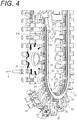
- the tool magazine 1 is provided with an endless guide rail 20 (to be understood as an annular rail) which follows a racetrack or obround path (to be understood as a circulation path), although other configurations are contemplated.
- the guide rail 20 has inner and outer guide surfaces 22, 24 for guiding guide members of the tool carriages 14.
- the upper surface 26 of the guide rail 20 may also provide guidance or support to the tool carriages 14.
- the guide rail 20 may be provided with a lower flange or lip 28 on each side of the guide rail 20 for providing support to the guide members of the tool carriages 14 (see, for example, FIG. 4 ).
- the tool carriages 14 are configured to follow the guide rail 20 through guide members of the tool carriages 14.
- the guide members include a pair of guide rollers 30 (to be understood as guide members). That is, each tool carriage 14 has a pair of guide rollers 30.
- the guide rollers 30 are spaced apart so as to be located on either side of the guide rail 20. Accordingly, a guide roller 30 located on the inside of the guide rail 20 will engage and be guided by one or more of the inner guide surface 22 and the lower lip 28 on the inside of the rail 20, and a guide roller 30 on the outside of the guide rail 20 will engage and be guided by one or more of the outer guide surface 24 and the lower lip 28 on the outside of the rail 20.
- the upper surface 26 of the guide rail 20 may also function as guidance or support to the guide member.
- the tool magazine 1 may contain other structure for guiding the tool carriages 14 instead of, or in addition to the guide rail 20.
- the magazine frame 2 includes a carriage support projection 3 which extends around all or part of the magazine frame 2 to provide additional guidance or support to the tool carriages 14.
- each pair of guide rollers 30 are rotatably connected to a roller mount 32.
- the roller mount 32 is oriented transversely to the guide rail 20.
- the roller mount 32 is connected to the underside of a carriage body 34.
- Each tool carriage 14 includes two spaced apart roller mounts 32 and two pairs of guide rollers 30 in such a manner that the tool carriages 14 can be smoothly guided along the guide rail 20.
- the illustrated guide rail 20 and guide roller configuration allow for very smooth operation of the magazine, and as an advantageous effect of its relatively open configuration, fouling, jamming and the like due to deposits or other foreign matters can be reduced.
- the tool carriage 14 also includes structure for engaging with a conveyance system to convey the tool carriages 14 in either direction along the rail 20.
- a conveyance system to convey the tool carriages 14 in either direction along the rail 20.
- two spaced-apart cam followers in the form of cam rollers 36 are rotatably mounted to the underside of the carriage body 34.
- the cam rollers 36 are mounted near the outside corners of the carriage body 34 and are configured to engage with a cam (sprocket 38).
- the sprocket 38 may be driven by a motor, such as a servo motor (not shown) for accurate control of the location of the tool carriages 14 along the guide rail 20.
- Each lateral side of the carriage body 34 includes connecting structure for connecting the tool carriage 14 to adjacent tool carriages 14.
- the tool magazine 1 includes a linkage 42.
- the carriage body 34 includes a hitch portion 40 for receiving the linkage 42.
- the linkage 42 connects the tool carriage 14 to adjacent tool carriages 14.
- Each end of the linkage 42 is rotatably captured in the adjacent hitch portion 40 of adjacent tool carriages 14 to connect the adjacent tool carriages 14 to one another.
- the hitch portion 40 is configured to allow the linkage 42 to rotate to at least some extent. Accordingly, the tool carriages 14 have freedom to move with respect to one another and therefore can travel around the curved portions of the guide rail 20.
- each linkage 42 includes a through opening 44 at each end through which a pin or fastener (not shown) extends within a through opening in the adjacent hitch portion 40.
- the rigid rotatable connection of the tool carriages 14 via the linkage 42 effectively provides reliable positioning of the tool carriages 14 at the tool exchange location 12, and further helps prevent jamming or rough operation caused by debris or foreign matters on or along the guide rail 20. This is because that debris or foreign matters can be avoided due to the degree of freedom of the tool carriages 14 to move with respect to one another.
- the guide rollers 30 may be configured to allow some lateral shifting with respect to the guide rail 20 for this purpose, as well as to allow the tool carriages 14 to move on the curved portions of the guide rail 20.
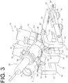
- FIG. 3 shows the entire configuration of one tool carriage 14 provided with two tool holders 16.
- the tool holder 16 includes a tool holder body 46.
- the tool holder body 46 is pivotally mounted to a tool holder support frame 48.
- the tool holder support frame 48 is connected to the outer facing surface of the carriage body 34.
- the tool holder 16 has a first tool pot socket 50 and a second tool pot socket 52.
- a normal line of an opening surface of the first tool pot socket 50 forms approximately 90° with a normal line of an opening surface of the second tool pot socket 52.
- the tool pot 18 mounted to the first tool pot socket 50 forms a predetermined angle with the tool pot 19 mounted to the second tool pot socket 52 in a pivoting direction about a predetermined pivot axis (tool holder pivot axis T) (i.e., an "L" shape or a “V” shape is formed by the tool pot 18 mounted to the first tool pot socket 50 and the tool pot 19 mounted to the second tool pot socket 52).
- a predetermined pivot axis tool holder pivot axis T
- Each tool pot socket 50, 52 is configured to receive a tool pot 18, 19. That is, the tool pots 18, 19 can be mounted to the tool holder 16 through the tool pot sockets 50, 52.
- the second tool pot socket 52 is best observed in FIG. 8 , which is visible because the second tool pot 19 is omitted in FIG. 8 . As shown in FIG.
- the tool pots 18, 19 have a cylindrical body 54 for receiving a tool adapter 56.
- the tool adapter 56 holds a tool, such as the first tool 8.
- Each tool adapter 56 is configured to hold a variety of different tools such as the tools 8, 10.
- each tool adapter 56 has a common outer configuration adapted to be releasable from the spindle 4 and the tool pots 18, 19. With this configuration, the tool pots 18, 19 and the spindle 4 can hold different tools.
- the tool holder body 46 includes a through opening near its apex.
- a shaft 60 extends through the through opening to define a tool holder pivot axis T (see FIG. 3 ).
- the tool holder 16 may pivot about the tool holder pivot axis T (to be understood as a predetermined pivot axis).
- Tool holder pivot axis T is generally parallel to the guide rail longitudinal axis and the direction of travel of the tool carriage 14 along straight line portions 20L of the guide rail 20.
- the shaft 60 extends between and is supported by opposing arms 62 of the tool holder support frame 48.
- the arms 62 are connected at a transverse mounting portion 63.
- the transverse mounting portion 63 is connected to the outside edge of the carriage body 34. As shown in FIG.
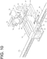
- a stop bar 61 spanning between the distal ends of the opposite arms 62 is provided to keep the tool holder 16 in the tool storage orientation.
- the tool holder body 46 is partially brought into contact with the stop bar 61.
- the stop bar 61 keeps the tool holder 16 from pivoting beyond the tool storage orientation in the counter-clockwise direction about the tool holder pivot axis T, as viewed in FIG. 10 .
- the tool holder body 46 and the tool pots 18, 19 are configured to pivot in a gap 65 (see FIG.
- the tool holder 16 is disposed to be pivotable about the predetermined pivot axis (tool holder pivot axis T) with respect to the tool carriage 14 (in particular, arm 62).
- the illustrated tool holders 16 are configured to pivot about the predetermined pivot axis to shift into the tool exchange orientations 82, 84, other ways of shifting the tool holders 16 is contemplated.
- Each tool holder 16 includes structure for engaging with the tool holder actuator 64.
- the tool holder 16 includes a cam follower in the form of two side-by-side cam rollers 66 (see FIG. 5 ) rotatably mounted to the outer facing surface 47 of the tool holder body 46.
- the cam rollers 66 are configured to rotate about an axis parallel to the tool holder pivot axis T of the tool holder 16.
- the tool holder actuator 64 includes a plurality of linearly shiftable shafts 68 which terminate in a u-shaped hook member 72.
- the u-shaped hook member 72 includes a cam surface 70 formed on the inner facing surface thereof.
- the cam rollers 66 of each of the tool holders 16 can pass through the opening in the u-shaped hook member 72 when the tool carriages 14 are conveyed along the guide rail 20 to bring the next desired tool to the tool exchange location 12.
- the tool holder actuator 64 allows the tool holder 16 to pivot about the tool holder pivot axis T at a predetermined position of the guide rail 20.
- the cam rollers 66 of the desired tool holder 16 will reside within the opening formed by the u-shaped hook member 72, and the linearly shiftable shafts 68 may be retracted to pull the u-shaped hook member 72 towards the tool holder actuator 64.
- the cam rollers 66 will be pulled towards the body of the tool holder actuator 64, causing the tool holder 16 to pivot about the tool holder pivot axis T.
- the tool holder actuator 64 will continue to retract the linearly shiftable shafts 68 and pivot the tool holder 16 until the tool holder 16 is in the desired first or second tool exchange orientations 82 or 84.
- the tool exchange arm 6 can access the first tool pot 18 to remove a tool therefrom or place a tool therein.
- the tool exchange arm 6 can access the second tool pot 19 to remove a tool therefrom or place a tool therein.
- the tool holder 16 is pivoted approximately 45 degrees to orient the tool holder 16 in the first tool exchange orientation 82.
- the first tool pot 18 is in the tool exchange location 12 and the tool exchange arm 6 can access the first tool pot 18.
- the longitudinal axis of the first tool pot 18 is parallel to the axis of the spindle 4 in the first tool exchange orientation 82.
- the tool exchange arm 6 can simultaneously remove tools from the spindle 4 and the tool pot 18, and then rotate a half turn to switch the locations of the removed tools and similarly place the removed tools in the tool pot 18 and spindle 4.
- the longitudinal axis of the second tool pot 19 is orthogonal to the axis of the spindle 4.
- the tool holder 16 is pivoted approximately 135 degrees about the tool holder pivot axis T from its initial tool storage orientation (shown in FIG. 3 ), i.e. approximately an additional 90 degrees from the first tool exchange orientation 82.
- the second tool pot 19 is in the tool exchange location 12 as shown in FIG. 7 .
- the first and second tool exchange orientations 82, 84 of the tool holder 16 place the first and second tool pots 18, 19 in the same tool exchange location relative to the tool exchange arm 6 and the tool carriage 14.
- the first and second tool pots 18, 19 may be moved into different positions relative to the tool exchange arm 6 for exchanging tools held by the first and second tool pots 18, 19.
- the tool pot stopper 74 shown in FIG. 9 stops the tool pots 18, 19.
- the tool pot stopper 74 may be used to provide a positive stop either the tool pot 18 or 19 at the tool exchange location 12 to ensure the proper positioning of the tool pots 18, 19 for error-free exchanging of tools.
- the tool pot stopper 74 can stop the first and second tool pots 18, 19 at the predetermined pivot position (tool exchange location 12) in the pivoting direction about the tool holder pivot axis T.
- the tool pot stopper 74 is particularly useful for stopping the first tool pot 18 at the first tool exchange orientation 82 in the tool exchange location 12, because the first tool pot 18 may be provided with a stop portion 58 on the body 54 of each pot as shown in FIG. 3 . As shown in FIG.
- the stop portion 58 of the first tool pot 18 abuts against the magazine frame 2 and hence, the tool holder 16 can be held in a stable orientation.
- the stop surface may be formed on the magazine frame 2 or the tool carriage 14 of the tool magazine 1.
- the tool pot stopper 74 includes a linear actuator (to be understood as an actuator) 76 and a stop member 78.
- the stop member 78 can receive the respective tool pots 18, 19 at the tool exchange location 12.
- the linear actuator 76 shifts the stop member 78 towards the tool exchange location 12 of the respective tool pots 18, 19.
- a limit 80 is mounted to the magazine frame 2 opposite from the linear actuator 76.
- the linear actuator 76 shifts the stop member 78 towards the limit 80 to keep the first tool pot 18 from being pivoted past the first tool exchange orientation 82 (i.e. moves the stop member 78 towards the extended position).
- the stop member 78 can receive the first tool pot 18 in the tool exchange location 12 (first tool exchange orientation 82). Once the tool exchange operation has been completed, the linear actuator 76 will retract the stop member 78 away from the limit 80 until the stop member 78 is needed again for a subsequent tool change operation. Optionally, the stop member 78 could remain in the extended position until the tool holder 16 is required to be shifted to the second tool exchange orientation 84 shown in FIG. 7 . Thus, the stop member 78 can stop the second tool pot 19 in the tool exchange location 12 (second tool exchange orientation 84).
- the tool pots 18, 19 are removably connected to the tool pot sockets 50, 52.
- the user may customize each tool holder 16 to have zero, one, or two tool pots 18, 19.
- the number of tools that may be held by the tool magazine 1 may be easily customized depending on the necessary number of tools to the end user.
- the tool magazine 1 has 20 tool carriages 14, each of which having two tool holders 16. Because each tool holder 16 has two tool pots 18, 19, each tool holder 16 may hold up to two tools.
- the tool magazine 1 can be configured to hold any number of tools between zero and 80. It is contemplated that the tool holders 16 may be configured to hold more than two tools to further expand the capacity of the tool magazine 1 and provide additional customization options.
- a greater or smaller number of tool carriages 14 could be provided, or each tool carriage 14 could be provided with one or more than two tool holders 16 to further vary the capacity of the tool magazine 1, as would be apparent to one of skill in the art.
- the tool holders 16 may be provided with a single tool pot 18 mounted to the first tool pot socket 50 without having a tool pot mounted to the second tool pot socket 52.
- Such a configuration shown in FIG. 8 may be used if the end user does not need the full capacity of the tool magazine 1, or anticipates later expansion of the tool set to be used with the machine tool.
- the tool magazine 1 illustrated in FIGS. 1 and 2 may be provided with 80 tool pots 18, 19 as shown, or if tool pots 19 are omitted from the second tool pot sockets 52 of each tool holder 16, the tool magazine 1 will have 40 tool pots 18, and accordingly have capacity for 40 tools.
- tool magazine 1 having a capacity of 40 or 80 tools, with the only difference being the number of tool pots 18, 19 used.
- tool pots 18, 19 may have an identical construction.
- the tool pots 18, 19 may be used at either the first or second tool pot socket 50, 52. Accordingly, a user may keep a number of tool pots 18, 19 on hand to customize the capacity of the tool magazine 1 if desired.
- the tool changer 100 includes: the tool magazine 1 that holds the tools 8; and the tool exchange arm 6 that exchanges the tools 8, 10 between the tool magazine 1 and the spindle 4. Further, the tool magazine 1 includes the guide rail 20, the tool carriage 14, the tool pots 18, 19, the tool holder 16, the tool holder actuator 64, and the tool pot stopper 74 that respectively have the above-mentioned configurations.
- the tool holder 16 has the first tool pot socket 50 and the second tool pot socket 52.
- the first tool pot 18 mounted to the first tool pot socket 50 forms a predetermined angle with the second tool pot 19 mounted to the second tool pot socket 52, in the pivoting direction about the tool holder pivot axis T.
- the tool magazine 1 that can be manufactured at low cost with simple configuration and can increase the number of tools to be stored. For example, whichever part of the tool magazine 1 the tools are stored, it is possible to shift the tool holder 16 from the tool storage orientation to the tool exchange orientation 82, 84, by the pivoting of the tool holder 16 about the pivot axis T one time. Accordingly, the tool holder 16 can be shifted from the tool storage orientation to the tool exchange orientation 82, 84 without using an expensive actuator such as a servo motor.
- the tool magazine 1 does not include an expensive actuator and complicated mechanisms and hence, the tool magazine 1 has the simple structure whereby a burden on maintenance of the tool magazine 1 can be reduced and the reduction of the cost of the tool magazine 1 can be also expected.
- the tool holder 16 has two tool pot sockets 50, 52 and hence, the number of tools which can be stored in the tool magazine 1 can be also increased without changing the size of the tool magazine 1.
- a chain or an endless band is used for moving the tool holder around the tool magazine.
- excessively large vibrations might be generated in the system thus giving rise to a drawback in reliability.
- a tool magazine having a chain drive mechanism needs to apply a proper tension to the chain for ensuring a proper operation, and hence requires proper setting of the tension and periodical maintenance.
- the tension of the chain changes over time due to a factor such as a load brought about by a tool held by a tool holder.
- the tool magazine 1 according to this embodiment adopts a method of moving the tool carriages 14 along the guide rail 20. Accordingly, the tool magazine 1 according to this embodiment does not have the above-mentioned respective drawbacks caused by tension of a chain.
- a plurality of tool carriages 14 is provided. Accordingly, the number of tools which can be stored in the tool magazine 1 can be further increased.
- the guide rail 20 has the straight line portion 20L, and the tool holder pivot axis T is parallel to the direction along which the tool carriages 14 move on the straight line portion 20L.
- the tool holder actuator 64 that allows the tool holder 16 to pivot about the pivot axis T can be fixed to the tool magazine 1 at the position orthogonal to a moving path (straight line portion 20L) of the tool carriages 14. Accordingly, the simple configuration makes it possible to avoid the interference between the tool carriage unit 64 and the moving tool carriage 14.
- the tool pot stopper 74 includes: the stop member 78 that receives the tool pot; and the linear actuator 76 that moves the stop member 78 to the tool exchange location 12.
- the linear actuator 76 can shift the stop member 78 to the tool exchange location 12.
- the tool pots 18, 19 can be fixed by the stop member 78. Accordingly, at the time of a tool exchange, the positioning of the tools can be performed accurately. Further, it is possible to prevent the tool holder 16 from being influenced by an impact generated when tools are placed in or removed from the tool pots 18, 19.
- a plurality of tool holders 16 are provided, and the tool carriage 14 has two or more tool holders 16.
- the tool pots 18, 19 are removable from the tool pot sockets 50, 52.
- the tool pots 18, 19 have an identical construction.
- a tool storing ability of the tool magazine 1 can be increased or can be flexibly changed depending on a size of the tool magazine 1.
- a guide groove is used to provide a path around which tool holders can shift.
- the tool magazine may have another drawback in reliability particularly attributed to chips scattered in a machining operation or other foreign matters entering the guide groove.
- the tool carriage 14 includes a guide member guided by the guide rail 20.
- the tool magazine 1 also includes the linkage structure that links the adjacent tool carriages 14.
- a system for moving a plurality of tool carriages 14 on the guide rail 20 has the simple structure and hence, foreign matters or the like adhering to the guide rail 20 can be easily removed.
Landscapes
- Engineering & Computer Science (AREA)
- Mechanical Engineering (AREA)
- Automatic Tool Replacement In Machine Tools (AREA)
Abstract
Description
- The invention relates to a tool magazine and a tool changer.
- Tool storage magazines (hereinafter, referred to as tool magazines) are known for storing tools (e.g. a plurality of cutting tools, such as drill bits, reamers, taps, and mills), when the tools are not in use, while keeping the tools accessible to be used in the tool spindle of a machining center when required. The tools are typically stored in tool pots which are configured to each releasably hold a single tool. When a particular tool is needed, the tool pot holding the desired tool is brought to a tool change location. A tool changer will then remove the desired tool from the tool pot, and if another tool is already in the spindle, it will simultaneously be removed by the tool changer and placed into the tool pot from which the desired tool has just been removed.
- For example,
Patent Literature 1,Patent Literature 2, andPatent Literature 3 each disclose the conventional technique relating to the invention. -
- Patent Literature 1:
U.S. Patent No. 5,688,215 - Patent Literature 2: Japanese Unexamined Patent Application Publication No.
S60-123241 - Patent Literature 3: Japanese Unexamined Utility Model Application Publication No.
S60-078240 - There has been a demand for a tool magazine that can increase the number of tools to be stored, and a tool changer provided with the tool magazine.
- Hence, an object of the invention is to provide a tool magazine that can be manufactured at low cost with simple configuration and can increase the number of tools to be stored, and a tool changer.
- In order to attain the above object, a tool magazine according to the invention includes: at least one tool carriage that is movable along a circulation path; a plurality of tool pots that hold a tool; a plurality of tool holders each having a plurality of tool pot sockets to which the tool pots are mountable, the tool holders being disposed to be pivotable about a predetermined pivot axis relative to the tool carriage; a turning unit that allows each of the tool holders to pivot about the predetermined pivot axis at a predetermined position on the circulation path; and a tool pot stopper that positions each of the tool pots. The plurality of tool pot sockets include a first tool pot socket and a second tool pot socket. The plurality of tool pots include a first tool pot and a second tool pot. In a state in which the first tool pot is mounted to the first tool pot socket and the second tool pot is mounted to the second tool pot socket, the first tool pot mounted to the first tool pot socket forms a predetermined angle with the second tool pot mounted to the second tool pot socket, in a pivoting direction about the predetermined pivot axis. The tool pot stopper is capable of stopping either one of the first tool pot and the second tool pot at a predetermined pivotable location in the pivoting direction.
- A tool changer according to the invention includes: a tool magazine that holds a tool; and a tool exchange arm that exchanges the tool between the tool magazine and a spindle. The tool magazine includes: at least one tool carriage that is movable along a circulation path; a plurality of tool pots that hold the tool; a plurality of tool holders each having a plurality of tool pot sockets to which the tool pots are mountable, the tool holders being disposed to be pivotable about a predetermined pivot axis relative to the tool carriage; a turning unit that allows each of the tool holders to pivot about the predetermined pivot axis at a predetermined position on the circulation path; and a tool pot stopper that positions each of the tool pots. The plurality of tool pot sockets include a first tool pot socket and a second tool pot socket. The plurality of tool pots include a first tool pot and a second tool pot. In a state in which the first tool pot is mounted to the first tool pot socket and the second tool pot is mounted to the second tool pot socket, the first tool pot mounted to the first tool pot socket forms a predetermined angle with the second tool pot mounted to the second tool pot socket, in a pivoting direction about the predetermined pivot axis. The tool pot stopper is capable of stopping either one of the first tool pot and the second tool pot at a predetermined pivotable location in the pivoting direction. The tool held by the tool pot stopped to the predetermined pivotable location is exchangeable between the tool pot and the spindle by the tool exchange arm.
- A tool magazine according to the invention includes: at least one tool carriage that is movable along a circulation path; a plurality of tool pots that hold a tool; a plurality of tool holders each having a plurality of tool pot sockets to which the tool pots are mountable, the tool holders being disposed to be pivotable about a predetermined pivot axis relative to the tool carriage; a turning unit that allows each of the tool holders to pivot about the predetermined pivot axis at a predetermined position on the circulation path; and a tool pot stopper that positions each of the tool pots. The plurality of tool pot sockets include a first tool pot socket and a second tool pot socket. The plurality of tool pots include a first tool pot and a second tool pot. In a state in which the first tool pot is mounted to the first tool pot socket and the second tool pot is mounted to the second tool pot socket, the first tool pot mounted to the first tool pot socket forms a predetermined angle with the second tool pot mounted to the second tool pot socket, in a pivoting direction about the predetermined pivot axis. The tool pot stopper is capable of stopping either one of the first tool pot and the second tool pot at a predetermined pivotable location in the pivoting direction.
- Accordingly, it is possible to provide the tool magazine that can be manufactured at low cost with simple configuration and can increase the number of tools to be stored. For example, whichever part of the tool magazine the tools are stored, it is possible to shift the tool holder from the tool storage orientation to the tool exchange orientation by the pivoting of the tool holder about the predetermined pivot axis one time. Accordingly, the tool holder can be shifted from the tool storage orientation to the tool exchange orientation without using an expensive actuator such as a servo motor. In this manner, the tool magazine does not include an expensive actuator and complicated mechanisms and hence, the tool magazine has the simple structure whereby a burden on maintenance of the tool magazine can be reduced and the reduction of the cost of the tool magazine can be also expected. Further, the tool holder has two tool pot sockets and hence, the number of tools to be stored in the tool magazine can be also increased without changing the size of the tool magazine.
-
-
FIG. 1 is a perspective view of a schematic configuration of an exemplary tool changer. -
FIG. 2 is a front view of a tool magazine. -
FIG. 3 is a perspective view of a tool carriage including tool holders. -
FIG. 4 is a perspective view of the underside of the tool magazine as viewed from the back side. -
FIG. 5 illustrates an arrangement state of some tool carriages. -
FIG. 6 is a fragmented perspective view illustrating the pivoting of the tool holder. -
FIG. 7 is a fragmented perspective view illustrating the pivoting of the tool holder. -
FIG. 8 is a fragmented perspective view illustrating the pivoting of the tool holder. -
FIG. 9 is a perspective view illustrating a configuration of the tool magazine around a tool exchange location. -
FIG. 10 is a perspective view illustrating the configuration of the tool magazine around the tool exchange location. - In accordance with one aspect, a tool magazine in one form includes an endless rail having opposite inner and outer surfaces. A carriage member is configured to travel about the endless rail. To guide the carriage member about the endless rail, the carriage member includes at least one rail guide member configured to engage with the endless rail at the inner and outer surfaces. The carriage member has a tool holder shiftably connected to the carriage member, and the tool holder includes a tool pot operably connected to the tool holder for holding a tool. An actuator is provided for shifting the tool holder at a tool exchange location. The actuator is configured to shift the tool holder from a tool storage orientation and a tool exchange orientation. In the tool storage orientation, the tool pot is oriented such that the carriage member may travel about the guide rail. In the tool exchange orientation, the tool pot is oriented for removing a tool held by the tool pot and placing another tool remote from the tool pot into the tool pot.
- In another form, a tool magazine includes an endless rail and a carriage member. The carriage member includes at least one rail guide member for guiding the carriage member about the endless rail. A tool holder including a plurality of tool pots each for holding a tool is connected to the carriage member. The tool holder is configured to be shifted into a plurality of different tool change orientations, including first and second tool exchange orientations. In the first tool exchange orientation, a tool held by one of the plurality of tool pots of the tool holder may be removed therefrom or a tool that is not held by any of the tool pots may be placed into one of the plurality of tool pots. In a second tool exchange orientation of the tool holder, another tool held by another one of the plurality of tool pots of the tool holder may be removed therefrom or the tool that is not held by any of the tool pots may be placed into the other one of the plurality of tool pots. Advantageously, the tool holder may be shifted into the first and second tool exchange orientations without moving the carriage members.
- In some forms, a tool carriage for a tool magazine may include a carriage member and a guide member connected to the carriage member for guiding the carriage member along a guide surface. A tool holder may have first and second tool pots each configured to hold a tool. The tool holder is pivotally connected to the carriage member and is pivotable between a plurality of locations, including a first tool exchange orientation, wherein the tool holder is pivoted such that a first tool may be removed from or inserted into the first tool pot, and a second tool exchange orientation different from the first tool exchange orientation, wherein the tool holder is pivoted such that a second tool may be removed from or inserted into the second tool pot.
- In other forms, a tool carriage for a tool magazine may include a carriage member for being guided about a tool magazine and a tool holder body pivotally connected to the carriage member. A plurality of tool pot sockets are disposed on the tool holder body for connecting one or more tool pots thereto. The tool holder body is configured to pivot between a plurality of tool exchange orientations corresponding to a common position of the one or more tool pots relative to the carriage member for removing a tool held by or placing a tool into the one or more tool pots. With this configuration, the user may select how many tools may be held by the tool carriage by attaching one or more tool pots to the tool holder at the tool pot sockets.
- In another form, a method of exchanging tools from a tool magazine includes at least one of the steps of: shifting one of a plurality of tool holders into a predetermined tool holder shifting position of the tool magazine; engaging a tool holder having first and second tool pots in the tool holder shifting position with an actuator for shifting the tool holder; shifting the tool holder with the actuator into one of first and second tool exchange orientations; and removing a tool from or inserting a tool into one of the first and second tool pots of the tool holder. Herein, the first tool exchange orientation is different from the second tool exchange orientation.
- In one form, the tool holder is shiftable between three locations, including a storage orientation, a first tool exchange orientation, and a second tool exchange orientation. In the default storage orientation, one or two tools are held and stored by tool pots of the tool holder and may be conveyed around a guide track. To orient the tool holder in the first tool exchange orientation, the desired tool holder is conveyed to the tool transfer location and the tool holder is pivoted outwardly by an actuator. Thus, the first tool may be removed by the automated tool changer and replaced by the tool previously in the spindle. If a second tool is present on the tool holder, the tool holder may be pivoted further by the actuator to the second tool exchange orientation. Thus, the second tool may be removed from the second tool holder and/or replaced by the tool changer. After the tools are exchanged, the tool holder is pivoted back to the storage orientation. Thus, the carriages may be moved by a sprocket to move the next desired tool holder to the tool transfer location. The invention will now be further described in connection with an illustrated embodiment, although the invention is not limited to the illustrated embodiment.
-
FIGS. 1 and2 illustrate atool changer 100 including atool magazine 1 and atool exchange arm 6. Thetool magazine 1 holds a plurality of tools until they are required at aspindle 4. Thetool magazine 1 includes a plurality of tool carriages 14 (seeFIG. 3 ). Each of thetool carriages 14 has at least onetool holder 16. Thetool holder 16 has at least onetool pot tool magazine 1 includes aguide rail 20, thetool carriages 14, thetool pots tool holders 16, atool holder actuator 64, and atool pot stopper 74. - The
tool magazine 1 is configured to be operated in conjunction with thetool exchange arm 6. Thetool exchange arm 6 includes a pair oftool grasping portions 7 for exchanging a tool between thetool magazine 1 and thespindle 4. Thetool grasping portions 7 disposed opposite each other on thetool exchange arm 6 exchanges afirst tool 8 held by atool pot second tool 10 at thespindle 4. The tools are exchanged at atool exchange location 12 of thetool magazine 1, as will be described in further detail below. Thetool magazine 1 has anopening 13 in amagazine frame 2 to allow thetool pots tool exchange arm 6 and to be rotated into thetool exchange location 12. In particular, thetool exchange arm 6 removes thefirst tool 8 from one of thetool pots tool exchange location 12 of thetool magazine 1 when the tool pot holding thefirst tool 8 is shifted into the tool exchange location 12 (seeFIGS. 6 ,7 ), and removes asecond tool 10 from thespindle 4, rotates, replaces thesecond tool 10 in thesame tool pot first tool 8 was removed, and places thefirst tool 8 in thespindle 4. Thetool exchange arm 6 also is configured to shift one tool at a time, i.e. placing thesecond tool 10 into anempty tool pot second tool 10 with afirst tool 8 or placing thefirst tool 8 into thespindle 4 without first removing asecond tool 10 from thespindle 4, i.e., when thespindle 4 is initially empty. - The
tool magazine 1 is provided with an endless guide rail 20 (to be understood as an annular rail) which follows a racetrack or obround path (to be understood as a circulation path), although other configurations are contemplated. As shown inFIG. 4 , theguide rail 20 has inner and outer guide surfaces 22, 24 for guiding guide members of thetool carriages 14. Referring to, for example,FIG. 5 , theupper surface 26 of theguide rail 20 may also provide guidance or support to thetool carriages 14. In addition, theguide rail 20 may be provided with a lower flange orlip 28 on each side of theguide rail 20 for providing support to the guide members of the tool carriages 14 (see, for example,FIG. 4 ). - The
tool carriages 14 are configured to follow theguide rail 20 through guide members of thetool carriages 14. The guide members include a pair of guide rollers 30 (to be understood as guide members). That is, eachtool carriage 14 has a pair ofguide rollers 30. Theguide rollers 30 are spaced apart so as to be located on either side of theguide rail 20. Accordingly, aguide roller 30 located on the inside of theguide rail 20 will engage and be guided by one or more of theinner guide surface 22 and thelower lip 28 on the inside of therail 20, and aguide roller 30 on the outside of theguide rail 20 will engage and be guided by one or more of theouter guide surface 24 and thelower lip 28 on the outside of therail 20. Theupper surface 26 of theguide rail 20 may also function as guidance or support to the guide member. Thetool magazine 1 may contain other structure for guiding thetool carriages 14 instead of, or in addition to theguide rail 20. As shown inFIG. 5 , themagazine frame 2 includes acarriage support projection 3 which extends around all or part of themagazine frame 2 to provide additional guidance or support to thetool carriages 14. - As shown in
FIG. 4 , each pair ofguide rollers 30 are rotatably connected to aroller mount 32. Theroller mount 32 is oriented transversely to theguide rail 20. Theroller mount 32 is connected to the underside of acarriage body 34. Eachtool carriage 14 includes two spaced apart roller mounts 32 and two pairs ofguide rollers 30 in such a manner that thetool carriages 14 can be smoothly guided along theguide rail 20. The illustratedguide rail 20 and guide roller configuration allow for very smooth operation of the magazine, and as an advantageous effect of its relatively open configuration, fouling, jamming and the like due to deposits or other foreign matters can be reduced. - The
tool carriage 14 also includes structure for engaging with a conveyance system to convey thetool carriages 14 in either direction along therail 20. In the illustrated embodiment, two spaced-apart cam followers in the form ofcam rollers 36 are rotatably mounted to the underside of thecarriage body 34. Thecam rollers 36 are mounted near the outside corners of thecarriage body 34 and are configured to engage with a cam (sprocket 38). Thesprocket 38 may be driven by a motor, such as a servo motor (not shown) for accurate control of the location of thetool carriages 14 along theguide rail 20. - Each lateral side of the
carriage body 34 includes connecting structure for connecting thetool carriage 14 toadjacent tool carriages 14. Thetool magazine 1 includes alinkage 42. As shown inFIG. 3 , thecarriage body 34 includes ahitch portion 40 for receiving thelinkage 42. Thelinkage 42 connects thetool carriage 14 toadjacent tool carriages 14. Each end of thelinkage 42 is rotatably captured in theadjacent hitch portion 40 ofadjacent tool carriages 14 to connect theadjacent tool carriages 14 to one another. Thehitch portion 40 is configured to allow thelinkage 42 to rotate to at least some extent. Accordingly, thetool carriages 14 have freedom to move with respect to one another and therefore can travel around the curved portions of theguide rail 20. In particular, eachlinkage 42 includes a throughopening 44 at each end through which a pin or fastener (not shown) extends within a through opening in theadjacent hitch portion 40. The rigid rotatable connection of thetool carriages 14 via thelinkage 42 effectively provides reliable positioning of thetool carriages 14 at thetool exchange location 12, and further helps prevent jamming or rough operation caused by debris or foreign matters on or along theguide rail 20. This is because that debris or foreign matters can be avoided due to the degree of freedom of thetool carriages 14 to move with respect to one another. Theguide rollers 30 may be configured to allow some lateral shifting with respect to theguide rail 20 for this purpose, as well as to allow thetool carriages 14 to move on the curved portions of theguide rail 20. - The
tool holders 16 and related structure will now be described in further detail.FIG. 3 shows the entire configuration of onetool carriage 14 provided with twotool holders 16. In one preferred form, thetool holder 16 includes atool holder body 46. Thetool holder body 46 is pivotally mounted to a toolholder support frame 48. The toolholder support frame 48 is connected to the outer facing surface of thecarriage body 34. Thetool holder 16 has a firsttool pot socket 50 and a secondtool pot socket 52. Although another form is also available, a normal line of an opening surface of the firsttool pot socket 50 forms approximately 90° with a normal line of an opening surface of the secondtool pot socket 52. That is, thetool pot 18 mounted to the firsttool pot socket 50 forms a predetermined angle with thetool pot 19 mounted to the secondtool pot socket 52 in a pivoting direction about a predetermined pivot axis (tool holder pivot axis T) (i.e., an "L" shape or a "V" shape is formed by thetool pot 18 mounted to the firsttool pot socket 50 and thetool pot 19 mounted to the second tool pot socket 52). Eachtool pot socket tool pot tool pots tool holder 16 through thetool pot sockets tool pot socket 52 is best observed inFIG. 8 , which is visible because thesecond tool pot 19 is omitted inFIG. 8 . As shown inFIG. 3 , thetool pots cylindrical body 54 for receiving atool adapter 56. Thetool adapter 56 holds a tool, such as thefirst tool 8. Eachtool adapter 56 is configured to hold a variety of different tools such as thetools tool adapter 56 has a common outer configuration adapted to be releasable from thespindle 4 and thetool pots tool pots spindle 4 can hold different tools. - The
tool holder body 46 includes a through opening near its apex. Ashaft 60 extends through the through opening to define a tool holder pivot axis T (seeFIG. 3 ). Thetool holder 16 may pivot about the tool holder pivot axis T (to be understood as a predetermined pivot axis). Tool holder pivot axis T is generally parallel to the guide rail longitudinal axis and the direction of travel of thetool carriage 14 alongstraight line portions 20L of theguide rail 20. Theshaft 60 extends between and is supported by opposingarms 62 of the toolholder support frame 48. Thearms 62 are connected at a transverse mountingportion 63. The transverse mountingportion 63 is connected to the outside edge of thecarriage body 34. As shown inFIG. 10 , astop bar 61 spanning between the distal ends of theopposite arms 62 is provided to keep thetool holder 16 in the tool storage orientation. When thetool holder 16 is in the tool storage orientation, thetool holder body 46 is partially brought into contact with thestop bar 61. In particular, thestop bar 61 keeps thetool holder 16 from pivoting beyond the tool storage orientation in the counter-clockwise direction about the tool holder pivot axis T, as viewed inFIG. 10 . Thetool holder body 46 and thetool pots FIG. 3 ) between theadjacent arms 62 when engaged by the tool holder actuator (to be understood as a turning unit) 64 from the tool storage orientation into first or secondtool exchange orientations tool holder 16 shown inFIGS. 6 and7 , which will be described in further detail below. As can be seen from the above description, thetool holder 16 is disposed to be pivotable about the predetermined pivot axis (tool holder pivot axis T) with respect to the tool carriage 14 (in particular, arm 62). Although the illustratedtool holders 16 are configured to pivot about the predetermined pivot axis to shift into thetool exchange orientations tool holders 16 is contemplated. - Each
tool holder 16 includes structure for engaging with thetool holder actuator 64. As shown inFIG. 3 , thetool holder 16 includes a cam follower in the form of two side-by-side cam rollers 66 (seeFIG. 5 ) rotatably mounted to the outer facingsurface 47 of thetool holder body 46. Thecam rollers 66 are configured to rotate about an axis parallel to the tool holder pivot axis T of thetool holder 16. As shown inFIGS. 5 ,9 , and10 , thetool holder actuator 64 includes a plurality of linearlyshiftable shafts 68 which terminate in au-shaped hook member 72. Theu-shaped hook member 72 includes acam surface 70 formed on the inner facing surface thereof. With the linearlyshiftable shafts 68 of thetool holder actuator 64 in an extended position, thecam rollers 66 of each of thetool holders 16 can pass through the opening in theu-shaped hook member 72 when thetool carriages 14 are conveyed along theguide rail 20 to bring the next desired tool to thetool exchange location 12. - The
tool holder actuator 64 allows thetool holder 16 to pivot about the tool holder pivot axis T at a predetermined position of theguide rail 20. When the desiredtool holder 16 arrives at thetool exchange location 12 of thetool magazine 1, thecam rollers 66 of the desiredtool holder 16 will reside within the opening formed by theu-shaped hook member 72, and the linearlyshiftable shafts 68 may be retracted to pull theu-shaped hook member 72 towards thetool holder actuator 64. Thecam rollers 66 will be pulled towards the body of thetool holder actuator 64, causing thetool holder 16 to pivot about the tool holder pivot axis T. Thetool holder actuator 64 will continue to retract the linearlyshiftable shafts 68 and pivot thetool holder 16 until thetool holder 16 is in the desired first or secondtool exchange orientations tool exchange orientation 82 shown inFIG. 6 , thetool exchange arm 6 can access thefirst tool pot 18 to remove a tool therefrom or place a tool therein. In the secondtool exchange orientation 84 shown inFIG. 7 , thetool exchange arm 6 can access thesecond tool pot 19 to remove a tool therefrom or place a tool therein. In the embodiment shown inFIG. 3 , thetool holder 16 is pivoted approximately 45 degrees to orient thetool holder 16 in the firsttool exchange orientation 82. Thus, thefirst tool pot 18 is in thetool exchange location 12 and thetool exchange arm 6 can access thefirst tool pot 18. In particular, the longitudinal axis of thefirst tool pot 18 is parallel to the axis of thespindle 4 in the firsttool exchange orientation 82. Thus, thetool exchange arm 6 can simultaneously remove tools from thespindle 4 and thetool pot 18, and then rotate a half turn to switch the locations of the removed tools and similarly place the removed tools in thetool pot 18 andspindle 4. When thetool holder 16 is in the firsttool exchange orientation 82, the longitudinal axis of thesecond tool pot 19 is orthogonal to the axis of thespindle 4. To shift thetool holder 16 into the secondtool exchange orientation 84, thetool holder 16 is pivoted approximately 135 degrees about the tool holder pivot axis T from its initial tool storage orientation (shown inFIG. 3 ), i.e. approximately an additional 90 degrees from the firsttool exchange orientation 82. Thus, thesecond tool pot 19 is in thetool exchange location 12 as shown inFIG. 7 . In order that the path of thetool exchange arm 6 to remove or replace tools in either of the first andsecond tool pots tool exchange orientations tool holder 16 place the first andsecond tool pots tool exchange arm 6 and thetool carriage 14. In other embodiments, the first andsecond tool pots tool exchange arm 6 for exchanging tools held by the first andsecond tool pots - The
tool pot stopper 74 shown inFIG. 9 stops thetool pots tool pot stopper 74 may be used to provide a positive stop either thetool pot tool exchange location 12 to ensure the proper positioning of thetool pots tool pot stopper 74 can stop the first andsecond tool pots tool pot stopper 74 is particularly useful for stopping thefirst tool pot 18 at the firsttool exchange orientation 82 in thetool exchange location 12, because thefirst tool pot 18 may be provided with astop portion 58 on thebody 54 of each pot as shown inFIG. 3 . As shown inFIG. 7 , when thesecond tool pot 19 is shifted into the secondtool exchange orientation 84, thestop portion 58 of thefirst tool pot 18 abuts against a stop surface on the transverse mountingportion 63 of thearm 62. Accordingly, it is possible to prevent the further pivoting of thetool holder 16 after thesecond tool pot 19 reaches the secondtool exchange orientation 84. With this configuration, in the case where thetool pot stopper 74 does not stop thefirst tool pot 18, thetool holder 16 is pivoted beyond the firsttool exchange orientation 82 until thefirst tool pot 18 abuts against the stop surface. Further, as shown inFIG. 5 , during a period that thetool holder 16 is in the tool storage orientation, thestop portion 58 of thefirst tool pot 18 abuts against themagazine frame 2 and hence, thetool holder 16 can be held in a stable orientation. The stop surface may be formed on themagazine frame 2 or thetool carriage 14 of thetool magazine 1. - As shown in, for example,
FIG. 9 , thetool pot stopper 74 includes a linear actuator (to be understood as an actuator) 76 and astop member 78. As shown inFIGS. 6 and7 , thestop member 78 can receive therespective tool pots tool exchange location 12. Thelinear actuator 76 shifts thestop member 78 towards thetool exchange location 12 of therespective tool pots limit 80 is mounted to themagazine frame 2 opposite from thelinear actuator 76. As shown inFIG. 6 , thelinear actuator 76 shifts thestop member 78 towards thelimit 80 to keep thefirst tool pot 18 from being pivoted past the first tool exchange orientation 82 (i.e. moves thestop member 78 towards the extended position). As shown inFIG. 6 , with this configuration, thestop member 78 can receive thefirst tool pot 18 in the tool exchange location 12 (first tool exchange orientation 82). Once the tool exchange operation has been completed, thelinear actuator 76 will retract thestop member 78 away from thelimit 80 until thestop member 78 is needed again for a subsequent tool change operation. Optionally, thestop member 78 could remain in the extended position until thetool holder 16 is required to be shifted to the secondtool exchange orientation 84 shown inFIG. 7 . Thus, thestop member 78 can stop thesecond tool pot 19 in the tool exchange location 12 (second tool exchange orientation 84). - Preferably, the
tool pots tool pot sockets tool holder 16 to have zero, one, or twotool pots tool magazine 1 may be easily customized depending on the necessary number of tools to the end user. For instance, in the illustrated embodiment, thetool magazine 1 has 20tool carriages 14, each of which having twotool holders 16. Because eachtool holder 16 has twotool pots tool holder 16 may hold up to two tools. Accordingly, thetool magazine 1 can be configured to hold any number of tools between zero and 80. It is contemplated that thetool holders 16 may be configured to hold more than two tools to further expand the capacity of thetool magazine 1 and provide additional customization options. In addition, a greater or smaller number oftool carriages 14 could be provided, or eachtool carriage 14 could be provided with one or more than twotool holders 16 to further vary the capacity of thetool magazine 1, as would be apparent to one of skill in the art. - In one form shown in
FIG. 8 , thetool holders 16 may be provided with asingle tool pot 18 mounted to the firsttool pot socket 50 without having a tool pot mounted to the secondtool pot socket 52. Such a configuration shown inFIG. 8 may be used if the end user does not need the full capacity of thetool magazine 1, or anticipates later expansion of the tool set to be used with the machine tool. Accordingly, thetool magazine 1 illustrated inFIGS. 1 and2 may be provided with 80tool pots tool pots 19 are omitted from the secondtool pot sockets 52 of eachtool holder 16, thetool magazine 1 will have 40tool pots 18, and accordingly have capacity for 40 tools. Advantageously, all of the same components may be used for atool magazine 1 having a capacity of 40 or 80 tools, with the only difference being the number oftool pots tool magazine 1 having a wide variety of tool capacities while maintaining the same sized footprint, thereby reducing cost. Further,tool pots tool pots tool pot socket tool pots tool magazine 1 if desired. - The
tool changer 100 according to this embodiment includes: thetool magazine 1 that holds thetools 8; and thetool exchange arm 6 that exchanges thetools tool magazine 1 and thespindle 4. Further, thetool magazine 1 includes theguide rail 20, thetool carriage 14, thetool pots tool holder 16, thetool holder actuator 64, and thetool pot stopper 74 that respectively have the above-mentioned configurations. Thetool holder 16 has the firsttool pot socket 50 and the secondtool pot socket 52. Thefirst tool pot 18 mounted to the firsttool pot socket 50 forms a predetermined angle with thesecond tool pot 19 mounted to the secondtool pot socket 52, in the pivoting direction about the tool holder pivot axis T. - Accordingly, it is possible to provide the
tool magazine 1 that can be manufactured at low cost with simple configuration and can increase the number of tools to be stored. For example, whichever part of thetool magazine 1 the tools are stored, it is possible to shift thetool holder 16 from the tool storage orientation to thetool exchange orientation tool holder 16 about the pivot axis T one time. Accordingly, thetool holder 16 can be shifted from the tool storage orientation to thetool exchange orientation tool magazine 1 does not include an expensive actuator and complicated mechanisms and hence, thetool magazine 1 has the simple structure whereby a burden on maintenance of thetool magazine 1 can be reduced and the reduction of the cost of thetool magazine 1 can be also expected. Further, thetool holder 16 has twotool pot sockets tool magazine 1 can be also increased without changing the size of thetool magazine 1. - It may also contemplated as to a tool magazine that a chain or an endless band is used for moving the tool holder around the tool magazine. In the tool magazine, however, excessively large vibrations might be generated in the system thus giving rise to a drawback in reliability. Further, a tool magazine having a chain drive mechanism needs to apply a proper tension to the chain for ensuring a proper operation, and hence requires proper setting of the tension and periodical maintenance. The tension of the chain changes over time due to a factor such as a load brought about by a tool held by a tool holder.
- The
tool magazine 1 according to this embodiment adopts a method of moving thetool carriages 14 along theguide rail 20. Accordingly, thetool magazine 1 according to this embodiment does not have the above-mentioned respective drawbacks caused by tension of a chain. - In the
tool magazine 1 according to this embodiment, a plurality oftool carriages 14 is provided. Accordingly, the number of tools which can be stored in thetool magazine 1 can be further increased. - In the
tool magazine 1 according to this embodiment, theguide rail 20 has thestraight line portion 20L, and the tool holder pivot axis T is parallel to the direction along which thetool carriages 14 move on thestraight line portion 20L. With this configuration, thetool holder actuator 64 that allows thetool holder 16 to pivot about the pivot axis T can be fixed to thetool magazine 1 at the position orthogonal to a moving path (straight line portion 20L) of thetool carriages 14. Accordingly, the simple configuration makes it possible to avoid the interference between thetool carriage unit 64 and the movingtool carriage 14. - In the
tool magazine 1 according to this embodiment, thetool pot stopper 74 includes: thestop member 78 that receives the tool pot; and thelinear actuator 76 that moves thestop member 78 to thetool exchange location 12. - Accordingly, the
linear actuator 76 can shift thestop member 78 to thetool exchange location 12. With this configuration, at the time of exchanging tools in thetool exchange location 12, thetool pots stop member 78. Accordingly, at the time of a tool exchange, the positioning of the tools can be performed accurately. Further, it is possible to prevent thetool holder 16 from being influenced by an impact generated when tools are placed in or removed from thetool pots - In the
tool magazine 1 according to this embodiment, a plurality oftool holders 16 are provided, and thetool carriage 14 has two ormore tool holders 16. Thetool pots tool pot sockets tool pots - Accordingly, a tool storing ability of the
tool magazine 1 can be increased or can be flexibly changed depending on a size of thetool magazine 1. - It may also be contemplated as to a tool magazine that a guide groove is used to provide a path around which tool holders can shift. The tool magazine may have another drawback in reliability particularly attributed to chips scattered in a machining operation or other foreign matters entering the guide groove.
- In the
tool magazine 1 according to this embodiment, thetool carriage 14 includes a guide member guided by theguide rail 20. Thetool magazine 1 also includes the linkage structure that links theadjacent tool carriages 14. - Accordingly, reliability in positioning the
tool carriage 14 at thetool exchange location 12 can be enhanced. Further, a system for moving a plurality oftool carriages 14 on theguide rail 20 has the simple structure and hence, foreign matters or the like adhering to theguide rail 20 can be easily removed. - Although the invention has been described in connection with a preferred embodiment, it will be understood that various changes in the details, materials, and arrangements of the parts and components that have been described and illustrated in order to explain the nature of the invention may be made by those skilled in the art within the principle and scope of the invention.
-
- 1:
- Tool magazine
- 4:
- Spindle
- 6:
- Tool exchange arm
- 7:
- Tool grasping portion
- 8, 10:
- Tool
- 12:
- Tool exchange location
- 14:
- Tool carriage
- 16:
- Tool holder
- 18:
- First tool pot
- 19:
- Second tool pot
- 20:
- Guide rail
- 20L:
- Straight line portion (of guide rail)
- 22:
- Inner guide surface
- 24:
- Outer guide surface
- 30:
- Guide roller
- 32:
- Roller mount
- 34:
- Carriage body
- 36:
- Cam roller
- 38:
- Sprocket
- 40:
- Hitch portion
- 42:
- Linkage
- 46:
- Tool holder body
- 48:
- Tool holder support frame
- 50:
- First tool pot socket
- 52:
- Second tool pot socket
- 54:
- Tool pot body
- 56:
- Tool adapter
- 58:
- Stop portion
- 60:
- Shaft
- 61:
- Stop bar
- 62:
- Arm
- 63:
- Transverse mounting portion
- 64:
- Tool holder actuator
- 66:
- Cam roller
- 68:
- Linearly shiftable shaft
- 70:
- Cam surface
- 72:
- U-shaped hook portion
- 74:
- Tool pot stopper
- 76:
- Linear actuator
- 78:
- Stop member
- 80:
- Limit
- 82:
- First tool exchange orientation
- 84:
- Second tool exchange orientation
- 100:
- Tool changer
- T:
- Tool holder pivot axis
Claims (7)
- A tool magazine comprising:at least one tool carriage (14) that is movable along a circulation path;a plurality of tool pots (18, 19) that hold a tool (8);a plurality of tool holders (16) each having a plurality of tool pot sockets (50, 52) to which the tool pots are mountable, the tool holders being disposed to be pivotable about a predetermined pivot axis (T) relative to the tool carriage;a turning unit (64) that allows each of the tool holders to pivot about the predetermined pivot axis at a predetermined position on the circulation path; anda tool pot stopper (74) that positions each of the tool pots,whereinthe plurality of tool pot sockets include a first tool pot socket (50) and a second tool pot socket (52),the plurality of tool pots include a first tool pot (18) and a second tool pot (19),in a state in which the first tool pot is mounted to the first tool pot socket and the second tool pot is mounted to the second tool pot socket, the first tool pot mounted to the first tool pot socket forms a predetermined angle with the second tool pot mounted to the second tool pot socket, in a pivoting direction about the predetermined pivot axis, andthe tool pot stopper is capable of stopping either one of the first tool pot and the second tool pot at a predetermined pivotable location in the pivoting direction.
- The tool magazine according to claim 1, further comprising:an annular rail (20) disposed along the circulation path and having a straight line portion (20L),whereinthe predetermined pivot axis is parallel to a direction along which the tool carriage moves on the straight line portion.
- The tool magazine according to claim 1 or 2, wherein
the tool pot stopper includes:a stop member (78) that stops either one of the first tool pot and the second tool pot; andan actuator (76) that moves the stop member. - The tool magazine according to any one of claims 1 to 3, wherein
the tool pots are removable from the tool pot sockets. - The tool magazine according to claim 4, wherein
the tool pots have an identical construction. - The tool magazine according to any one of claims 1 to 5, wherein
the tool carriage includes a plurality of tool carriages, and
each of the tool carriages includes:a guide member (30) guided by the annular rail; anda linkage structure that links the adjacent tool carriages. - A tool changer comprising:a tool magazine (1) that holds a tool; anda tool exchange arm (6) that exchanges the tool (8) between the tool magazine and a spindle (4),whereinthe tool magazine includes:at least one tool carriage (14) that is movable along a circulation path;a plurality of tool pots (18, 19) that hold the tool (8);a plurality of tool holders (16) each having a plurality of tool pot sockets (50, 52) to which the tool pots are mountable, the tool holders being disposed to be pivotable about a predetermined pivot axis (T) relative to the tool carriage;a turning unit (64) that allows each of the tool holders to pivot about the predetermined pivot axis at a predetermined position on the circulation path; anda tool pot stopper (74) that positions each of the tool pots,the plurality of tool pot sockets include a first tool pot socket (50) and a second tool pot socket (52),the plurality of tool pots include a first tool pot (18) and a second tool pot (19),in a state in which the first tool pot is mounted to the first tool pot socket and the second tool pot is mounted to the second tool pot socket, the first tool pot mounted to the first tool pot socket forms a predetermined angle with the second tool pot mounted to the second tool pot socket, in a pivoting direction about the predetermined pivot axis,the tool pot stopper is capable of stopping either one of the first tool pot and the second tool pot at a predetermined pivotable location in the pivoting direction, andthe tool held by the tool pot stopped to the predetermined pivotable location is exchangeable between the tool pot and the spindle by the tool exchange arm.
Applications Claiming Priority (2)
| Application Number | Priority Date | Filing Date | Title |
|---|---|---|---|
| US201462046808P | 2014-09-05 | 2014-09-05 | |
| PCT/JP2015/075229 WO2016035886A1 (en) | 2014-09-05 | 2015-09-04 | Tool magazine and tool exchange device |
Publications (3)
| Publication Number | Publication Date |
|---|---|
| EP3135428A1 true EP3135428A1 (en) | 2017-03-01 |
| EP3135428A4 EP3135428A4 (en) | 2017-11-08 |
| EP3135428B1 EP3135428B1 (en) | 2018-10-24 |
Family
ID=55439940
Family Applications (1)
| Application Number | Title | Priority Date | Filing Date |
|---|---|---|---|
| EP15838559.1A Active EP3135428B1 (en) | 2014-09-05 | 2015-09-04 | Tool magazine and tool exchange device |
Country Status (5)
| Country | Link |
|---|---|
| US (1) | US9751173B2 (en) |
| EP (1) | EP3135428B1 (en) |
| JP (1) | JP5925396B1 (en) |
| CN (1) | CN105873721B (en) |
| WO (1) | WO2016035886A1 (en) |
Families Citing this family (11)
| Publication number | Priority date | Publication date | Assignee | Title |
|---|---|---|---|---|
| CN105705298B (en) * | 2013-11-08 | 2017-12-08 | 株式会社牧野铣床制作所 | chain type tool magazine |
| JP2017039573A (en) * | 2015-08-19 | 2017-02-23 | キタムラ機械株式会社 | Pot carrying device |
| CN108297465A (en) * | 2016-08-31 | 2018-07-20 | 山东豪迈机械科技股份有限公司 | Cutter, cutter holding device and the tyre tread automatic processing system including the device |
| TWI716887B (en) * | 2019-05-28 | 2021-01-21 | 陳君杰 | Tool changing unit and tool changing device with the tool changing unit |
| CN112692628A (en) * | 2019-10-23 | 2021-04-23 | 冈田精机丹阳有限公司 | Movable beam type gantry machining center machine tool magazine |
| TWI751802B (en) * | 2020-11-23 | 2022-01-01 | 聖杰國際股份有限公司 | Chain Tool Magazine |
| JP7501404B2 (en) * | 2021-02-26 | 2024-06-18 | ブラザー工業株式会社 | Tool magazines and machine tools |
| JP7501405B2 (en) * | 2021-02-26 | 2024-06-18 | ブラザー工業株式会社 | Tool magazines and machine tools |
| CN112894978B (en) * | 2021-03-23 | 2024-09-17 | 东莞市陆陆兴工业自动化科技有限公司 | Three-dimensional circulation tool magazine |
| TWI775400B (en) * | 2021-04-22 | 2022-08-21 | 聖杰國際股份有限公司 | Chain type tool magazine with chain tension adjustment mechanism |
| CN113798894B (en) * | 2021-11-19 | 2022-03-01 | 江苏德杰机械设备有限公司 | Three-dimensional rail conveying type tool magazine |
Family Cites Families (34)
| Publication number | Priority date | Publication date | Assignee | Title |
|---|---|---|---|---|
| US4117586A (en) | 1976-04-12 | 1978-10-03 | Hitachi Seiki Co., Ltd. | Machine tool with automatic tool changer |
| JPS5939254B2 (en) * | 1976-04-16 | 1984-09-21 | 三井精機工業株式会社 | Machine tool tool retrieval device |
| GB1580086A (en) | 1976-12-06 | 1980-11-26 | Toyoda Machine Works Ltd | Machine tool with automatic tool change apparatus |
| JPS5939256B2 (en) | 1977-11-04 | 1984-09-21 | 東芝機械株式会社 | automatic tool changer |
| JPS5822302B2 (en) * | 1979-07-24 | 1983-05-07 | 遠州製作株式会社 | Tool storage cylinder tilting device for tool storage magazine |
| JPS5621744A (en) * | 1979-07-28 | 1981-02-28 | Enshu Ltd | Device for slanting tool receiving cylinder in tool storing magazine |
| US4384397A (en) | 1980-04-22 | 1983-05-24 | Giddings & Lewis, Inc. | Tool changing machining center with swing spindle |
| JPS5741146A (en) | 1980-08-15 | 1982-03-08 | Okuma Howa Kikai Kk | Machine tool |
| US4399603A (en) | 1980-11-17 | 1983-08-23 | Giddings & Lewis, Inc. | Power grip tool exchange arm for machining center |
| JPS6078240U (en) | 1983-11-02 | 1985-05-31 | 三菱重工業株式会社 | Tool magazine for automatic tool changer |
| JPS60123241A (en) | 1983-12-02 | 1985-07-01 | Aioi Seiki Kk | Tool replacing device in machining center |
| JPS60123240A (en) * | 1983-12-02 | 1985-07-01 | Aioi Seiki Kk | Tool replacing device in machining center |
| DE3408734A1 (en) | 1984-03-09 | 1985-09-19 | Friedrich Deckel AG, 8000 München | DEVICE FOR CHANGING TOOLS OR THE LIKE IN THE WORK SPINDLE OF A MACHINE TOOL |
| US4699276A (en) | 1986-07-31 | 1987-10-13 | Kearney & Trecker Corporation | Chain-type tool storage magazine |
| CH671907A5 (en) * | 1986-11-03 | 1989-10-13 | Starrfraesmaschinen Ag | |
| DE8905795U1 (en) | 1989-05-09 | 1989-07-20 | MAHO AG, 8962 Pfronten | Tool changer for program-controlled machine tools |
| DE4116091C1 (en) | 1991-05-17 | 1992-08-13 | Hirschmann Gmbh, 7239 Fluorn-Winzeln, De | |
| US5194061A (en) | 1992-03-16 | 1993-03-16 | Ott Maschinentechnik Gmbh | Tool changer |
| DE4331064A1 (en) | 1993-09-13 | 1995-03-16 | Steinel Bernhard Werkzeugmasch | Tool changer for a machining center |
| DE4421385C2 (en) * | 1994-06-18 | 1997-01-23 | Chiron Werke Gmbh | Machine tool with a tool changing device |
| JP2865195B2 (en) | 1995-04-07 | 1999-03-08 | 豊和工業株式会社 | Tool changing method and device in machining center |
| JP3022249B2 (en) | 1995-04-07 | 2000-03-15 | 豊和工業株式会社 | Tool magazine equipment for machine tools |
| US6442815B1 (en) | 2000-04-18 | 2002-09-03 | The Regents Of The University Of Michigan | Reconfigurable automatic tool changer |
| ITTO20010230A1 (en) * | 2001-03-13 | 2002-09-13 | Pluritec S P A | HIGH CAPACITY TOOL WAREHOUSE FOR A MACHINE TOOL FOR THE PROCESSING OF BOARDS OF PRINTED CIRCUITS. |
| JP2002283164A (en) * | 2001-03-23 | 2002-10-03 | Tsubakimoto Chain Co | Tool pot rotating chain |
| KR20030069674A (en) | 2002-02-22 | 2003-08-27 | 두산메카텍 주식회사 | An automatic tool changer of Vertical Machining Center |
| DE10344642A1 (en) * | 2003-09-17 | 2005-05-12 | Chiron Werke Gmbh | Machine tool with transport chain |
| EP1810778B1 (en) * | 2006-01-18 | 2008-07-16 | Hüller Hille GmbH | Tool magazine with a storage wheel with two peripherical rows of tool holders |
| US7575543B1 (en) * | 2008-09-22 | 2009-08-18 | Ying Sun | Bit-storing apparatus |
| CN201419334Y (en) * | 2009-06-16 | 2010-03-10 | 杭州光大机械有限公司 | Automatic tool magazine device for processing central machine tools |
| GB2487520B (en) * | 2009-11-18 | 2013-01-09 | Komatsu Ntc Ltd | Tool magazine and machining center |
| US8632447B2 (en) * | 2011-01-05 | 2014-01-21 | Chen Sound Industrial Co., Ltd. | Chain-type tool magazine |
| JP5429221B2 (en) | 2011-03-31 | 2014-02-26 | ブラザー工業株式会社 | Tool changer and machine tool provided with tool changer |
| DE102012213207A1 (en) * | 2012-07-26 | 2014-01-30 | Deckel Maho Pfronten Gmbh | Tool holder for holding and locking a tool taper on a tool magazine, unlocking device and tool magazine |
-
2015
- 2015-09-04 EP EP15838559.1A patent/EP3135428B1/en active Active
- 2015-09-04 CN CN201580003485.2A patent/CN105873721B/en active Active
- 2015-09-04 WO PCT/JP2015/075229 patent/WO2016035886A1/en not_active Ceased
- 2015-09-04 JP JP2015561784A patent/JP5925396B1/en active Active
-
2016
- 2016-11-11 US US15/348,987 patent/US9751173B2/en active Active
Also Published As
| Publication number | Publication date |
|---|---|
| EP3135428A4 (en) | 2017-11-08 |
| EP3135428B1 (en) | 2018-10-24 |
| US20170057032A1 (en) | 2017-03-02 |
| CN105873721B (en) | 2017-04-12 |
| US9751173B2 (en) | 2017-09-05 |
| JPWO2016035886A1 (en) | 2017-04-27 |
| JP5925396B1 (en) | 2016-05-25 |
| CN105873721A (en) | 2016-08-17 |
| WO2016035886A1 (en) | 2016-03-10 |
Similar Documents
| Publication | Publication Date | Title |
|---|---|---|
| EP3135428B1 (en) | Tool magazine and tool exchange device | |
| US9168609B2 (en) | Spot welding cap changer | |
| US6514183B2 (en) | Machine tool | |
| US10377004B2 (en) | Tool magazine | |
| US10369671B2 (en) | Chain magazine for holding tools | |
| CN106493597B (en) | machine tool | |
| JP4970761B2 (en) | Tool changer and machine tool equipped with the same | |
| CN105473278A (en) | machine tool | |
| KR20130030928A (en) | Device for transporting a tool in the tool magazine of a machine tool | |
| CN105764648B (en) | machine tool | |
| US4443928A (en) | Multiple-spindle tool changer | |
| US7207611B2 (en) | Tool handling device | |
| US20100210433A1 (en) | Tool Changing Device | |
| JP4827912B2 (en) | Machine tool system | |
| JPH0569652B2 (en) | ||
| JP3831884B2 (en) | Machine tool with automatic tool changer | |
| KR102065854B1 (en) | Automatic tool changer of machine tool | |
| KR20160057850A (en) | Tool magazine and tool pot carrier unit |
Legal Events
| Date | Code | Title | Description |
|---|---|---|---|
| STAA | Information on the status of an ep patent application or granted ep patent |
Free format text: STATUS: THE INTERNATIONAL PUBLICATION HAS BEEN MADE |
|
| PUAI | Public reference made under article 153(3) epc to a published international application that has entered the european phase |
Free format text: ORIGINAL CODE: 0009012 |
|
| STAA | Information on the status of an ep patent application or granted ep patent |
Free format text: STATUS: REQUEST FOR EXAMINATION WAS MADE |
|
| 17P | Request for examination filed |
Effective date: 20161124 |
|
| AK | Designated contracting states |
Kind code of ref document: A1 Designated state(s): AL AT BE BG CH CY CZ DE DK EE ES FI FR GB GR HR HU IE IS IT LI LT LU LV MC MK MT NL NO PL PT RO RS SE SI SK SM TR |
|
| AX | Request for extension of the european patent |
Extension state: BA ME |
|
| A4 | Supplementary search report drawn up and despatched |
Effective date: 20171009 |
|
| RIC1 | Information provided on ipc code assigned before grant |
Ipc: B23Q 3/157 20060101AFI20171002BHEP |
|
| DAV | Request for validation of the european patent (deleted) | ||
| DAX | Request for extension of the european patent (deleted) | ||
| GRAP | Despatch of communication of intention to grant a patent |
Free format text: ORIGINAL CODE: EPIDOSNIGR1 |
|
| STAA | Information on the status of an ep patent application or granted ep patent |
Free format text: STATUS: GRANT OF PATENT IS INTENDED |
|
| INTG | Intention to grant announced |
Effective date: 20180419 |
|
| GRAS | Grant fee paid |
Free format text: ORIGINAL CODE: EPIDOSNIGR3 |
|
| GRAA | (expected) grant |
Free format text: ORIGINAL CODE: 0009210 |
|
| STAA | Information on the status of an ep patent application or granted ep patent |
Free format text: STATUS: THE PATENT HAS BEEN GRANTED |
|
| AK | Designated contracting states |
Kind code of ref document: B1 Designated state(s): AL AT BE BG CH CY CZ DE DK EE ES FI FR GB GR HR HU IE IS IT LI LT LU LV MC MK MT NL NO PL PT RO RS SE SI SK SM TR |
|
| REG | Reference to a national code |
Ref country code: CH Ref legal event code: EP |
|
| REG | Reference to a national code |
Ref country code: IE Ref legal event code: FG4D |
|
| REG | Reference to a national code |
Ref country code: AT Ref legal event code: REF Ref document number: 1056115 Country of ref document: AT Kind code of ref document: T Effective date: 20181115 |
|
| REG | Reference to a national code |
Ref country code: DE Ref legal event code: R096 Ref document number: 602015018889 Country of ref document: DE |
|
| REG | Reference to a national code |
Ref country code: NL Ref legal event code: MP Effective date: 20181024 |
|
| REG | Reference to a national code |
Ref country code: LT Ref legal event code: MG4D |
|
| REG | Reference to a national code |
Ref country code: AT Ref legal event code: MK05 Ref document number: 1056115 Country of ref document: AT Kind code of ref document: T Effective date: 20181024 |
|
| PG25 | Lapsed in a contracting state [announced via postgrant information from national office to epo] |
Ref country code: NL Free format text: LAPSE BECAUSE OF FAILURE TO SUBMIT A TRANSLATION OF THE DESCRIPTION OR TO PAY THE FEE WITHIN THE PRESCRIBED TIME-LIMIT Effective date: 20181024 |
|
| PG25 | Lapsed in a contracting state [announced via postgrant information from national office to epo] |
Ref country code: ES Free format text: LAPSE BECAUSE OF FAILURE TO SUBMIT A TRANSLATION OF THE DESCRIPTION OR TO PAY THE FEE WITHIN THE PRESCRIBED TIME-LIMIT Effective date: 20181024 Ref country code: LT Free format text: LAPSE BECAUSE OF FAILURE TO SUBMIT A TRANSLATION OF THE DESCRIPTION OR TO PAY THE FEE WITHIN THE PRESCRIBED TIME-LIMIT Effective date: 20181024 Ref country code: BG Free format text: LAPSE BECAUSE OF FAILURE TO SUBMIT A TRANSLATION OF THE DESCRIPTION OR TO PAY THE FEE WITHIN THE PRESCRIBED TIME-LIMIT Effective date: 20190124 Ref country code: IS Free format text: LAPSE BECAUSE OF FAILURE TO SUBMIT A TRANSLATION OF THE DESCRIPTION OR TO PAY THE FEE WITHIN THE PRESCRIBED TIME-LIMIT Effective date: 20190224 Ref country code: PL Free format text: LAPSE BECAUSE OF FAILURE TO SUBMIT A TRANSLATION OF THE DESCRIPTION OR TO PAY THE FEE WITHIN THE PRESCRIBED TIME-LIMIT Effective date: 20181024 Ref country code: NO Free format text: LAPSE BECAUSE OF FAILURE TO SUBMIT A TRANSLATION OF THE DESCRIPTION OR TO PAY THE FEE WITHIN THE PRESCRIBED TIME-LIMIT Effective date: 20190124 Ref country code: HR Free format text: LAPSE BECAUSE OF FAILURE TO SUBMIT A TRANSLATION OF THE DESCRIPTION OR TO PAY THE FEE WITHIN THE PRESCRIBED TIME-LIMIT Effective date: 20181024 Ref country code: AT Free format text: LAPSE BECAUSE OF FAILURE TO SUBMIT A TRANSLATION OF THE DESCRIPTION OR TO PAY THE FEE WITHIN THE PRESCRIBED TIME-LIMIT Effective date: 20181024 Ref country code: LV Free format text: LAPSE BECAUSE OF FAILURE TO SUBMIT A TRANSLATION OF THE DESCRIPTION OR TO PAY THE FEE WITHIN THE PRESCRIBED TIME-LIMIT Effective date: 20181024 Ref country code: FI Free format text: LAPSE BECAUSE OF FAILURE TO SUBMIT A TRANSLATION OF THE DESCRIPTION OR TO PAY THE FEE WITHIN THE PRESCRIBED TIME-LIMIT Effective date: 20181024 |
|
| PG25 | Lapsed in a contracting state [announced via postgrant information from national office to epo] |
Ref country code: SE Free format text: LAPSE BECAUSE OF FAILURE TO SUBMIT A TRANSLATION OF THE DESCRIPTION OR TO PAY THE FEE WITHIN THE PRESCRIBED TIME-LIMIT Effective date: 20181024 Ref country code: GR Free format text: LAPSE BECAUSE OF FAILURE TO SUBMIT A TRANSLATION OF THE DESCRIPTION OR TO PAY THE FEE WITHIN THE PRESCRIBED TIME-LIMIT Effective date: 20190125 Ref country code: AL Free format text: LAPSE BECAUSE OF FAILURE TO SUBMIT A TRANSLATION OF THE DESCRIPTION OR TO PAY THE FEE WITHIN THE PRESCRIBED TIME-LIMIT Effective date: 20181024 Ref country code: RS Free format text: LAPSE BECAUSE OF FAILURE TO SUBMIT A TRANSLATION OF THE DESCRIPTION OR TO PAY THE FEE WITHIN THE PRESCRIBED TIME-LIMIT Effective date: 20181024 Ref country code: PT Free format text: LAPSE BECAUSE OF FAILURE TO SUBMIT A TRANSLATION OF THE DESCRIPTION OR TO PAY THE FEE WITHIN THE PRESCRIBED TIME-LIMIT Effective date: 20190224 |
|
| REG | Reference to a national code |
Ref country code: DE Ref legal event code: R097 Ref document number: 602015018889 Country of ref document: DE |
|
| PG25 | Lapsed in a contracting state [announced via postgrant information from national office to epo] |
Ref country code: DK Free format text: LAPSE BECAUSE OF FAILURE TO SUBMIT A TRANSLATION OF THE DESCRIPTION OR TO PAY THE FEE WITHIN THE PRESCRIBED TIME-LIMIT Effective date: 20181024 Ref country code: CZ Free format text: LAPSE BECAUSE OF FAILURE TO SUBMIT A TRANSLATION OF THE DESCRIPTION OR TO PAY THE FEE WITHIN THE PRESCRIBED TIME-LIMIT Effective date: 20181024 |
|
| PG25 | Lapsed in a contracting state [announced via postgrant information from national office to epo] |
Ref country code: SK Free format text: LAPSE BECAUSE OF FAILURE TO SUBMIT A TRANSLATION OF THE DESCRIPTION OR TO PAY THE FEE WITHIN THE PRESCRIBED TIME-LIMIT Effective date: 20181024 Ref country code: RO Free format text: LAPSE BECAUSE OF FAILURE TO SUBMIT A TRANSLATION OF THE DESCRIPTION OR TO PAY THE FEE WITHIN THE PRESCRIBED TIME-LIMIT Effective date: 20181024 Ref country code: EE Free format text: LAPSE BECAUSE OF FAILURE TO SUBMIT A TRANSLATION OF THE DESCRIPTION OR TO PAY THE FEE WITHIN THE PRESCRIBED TIME-LIMIT Effective date: 20181024 Ref country code: SM Free format text: LAPSE BECAUSE OF FAILURE TO SUBMIT A TRANSLATION OF THE DESCRIPTION OR TO PAY THE FEE WITHIN THE PRESCRIBED TIME-LIMIT Effective date: 20181024 |
|
| PLBE | No opposition filed within time limit |
Free format text: ORIGINAL CODE: 0009261 |
|
| STAA | Information on the status of an ep patent application or granted ep patent |
Free format text: STATUS: NO OPPOSITION FILED WITHIN TIME LIMIT |
|
| 26N | No opposition filed |
Effective date: 20190725 |
|
| PG25 | Lapsed in a contracting state [announced via postgrant information from national office to epo] |
Ref country code: SI Free format text: LAPSE BECAUSE OF FAILURE TO SUBMIT A TRANSLATION OF THE DESCRIPTION OR TO PAY THE FEE WITHIN THE PRESCRIBED TIME-LIMIT Effective date: 20181024 |
|
| PG25 | Lapsed in a contracting state [announced via postgrant information from national office to epo] |
Ref country code: TR Free format text: LAPSE BECAUSE OF FAILURE TO SUBMIT A TRANSLATION OF THE DESCRIPTION OR TO PAY THE FEE WITHIN THE PRESCRIBED TIME-LIMIT Effective date: 20181024 |
|
| PG25 | Lapsed in a contracting state [announced via postgrant information from national office to epo] |
Ref country code: MC Free format text: LAPSE BECAUSE OF FAILURE TO SUBMIT A TRANSLATION OF THE DESCRIPTION OR TO PAY THE FEE WITHIN THE PRESCRIBED TIME-LIMIT Effective date: 20181024 |
|
| REG | Reference to a national code |
Ref country code: CH Ref legal event code: PL |
|
| PG25 | Lapsed in a contracting state [announced via postgrant information from national office to epo] |
Ref country code: IE Free format text: LAPSE BECAUSE OF NON-PAYMENT OF DUE FEES Effective date: 20190904 Ref country code: LU Free format text: LAPSE BECAUSE OF NON-PAYMENT OF DUE FEES Effective date: 20190904 Ref country code: CH Free format text: LAPSE BECAUSE OF NON-PAYMENT OF DUE FEES Effective date: 20190930 Ref country code: LI Free format text: LAPSE BECAUSE OF NON-PAYMENT OF DUE FEES Effective date: 20190930 |
|
| REG | Reference to a national code |
Ref country code: BE Ref legal event code: MM Effective date: 20190930 |
|
| PG25 | Lapsed in a contracting state [announced via postgrant information from national office to epo] |
Ref country code: BE Free format text: LAPSE BECAUSE OF NON-PAYMENT OF DUE FEES Effective date: 20190930 |
|
| PG25 | Lapsed in a contracting state [announced via postgrant information from national office to epo] |
Ref country code: CY Free format text: LAPSE BECAUSE OF FAILURE TO SUBMIT A TRANSLATION OF THE DESCRIPTION OR TO PAY THE FEE WITHIN THE PRESCRIBED TIME-LIMIT Effective date: 20181024 |
|
| PG25 | Lapsed in a contracting state [announced via postgrant information from national office to epo] |
Ref country code: MT Free format text: LAPSE BECAUSE OF FAILURE TO SUBMIT A TRANSLATION OF THE DESCRIPTION OR TO PAY THE FEE WITHIN THE PRESCRIBED TIME-LIMIT Effective date: 20181024 Ref country code: HU Free format text: LAPSE BECAUSE OF FAILURE TO SUBMIT A TRANSLATION OF THE DESCRIPTION OR TO PAY THE FEE WITHIN THE PRESCRIBED TIME-LIMIT; INVALID AB INITIO Effective date: 20150904 |
|
| PG25 | Lapsed in a contracting state [announced via postgrant information from national office to epo] |
Ref country code: MK Free format text: LAPSE BECAUSE OF FAILURE TO SUBMIT A TRANSLATION OF THE DESCRIPTION OR TO PAY THE FEE WITHIN THE PRESCRIBED TIME-LIMIT Effective date: 20181024 |
|
| PGFP | Annual fee paid to national office [announced via postgrant information from national office to epo] |
Ref country code: DE Payment date: 20240730 Year of fee payment: 10 |
|
| PGFP | Annual fee paid to national office [announced via postgrant information from national office to epo] |
Ref country code: GB Payment date: 20240801 Year of fee payment: 10 |
|
| PGFP | Annual fee paid to national office [announced via postgrant information from national office to epo] |
Ref country code: FR Payment date: 20240808 Year of fee payment: 10 |
|
| PGFP | Annual fee paid to national office [announced via postgrant information from national office to epo] |
Ref country code: IT Payment date: 20240812 Year of fee payment: 10 |