EP3135398A1 - Three-dimensional manufacturing methods and systems for turbine components - Google Patents
Three-dimensional manufacturing methods and systems for turbine components Download PDFInfo
- Publication number
- EP3135398A1 EP3135398A1 EP16178546.4A EP16178546A EP3135398A1 EP 3135398 A1 EP3135398 A1 EP 3135398A1 EP 16178546 A EP16178546 A EP 16178546A EP 3135398 A1 EP3135398 A1 EP 3135398A1
- Authority
- EP
- European Patent Office
- Prior art keywords
- mold
- core
- creating
- dissolvable
- dissolvable ceramic
- Prior art date
- Legal status (The legal status is an assumption and is not a legal conclusion. Google has not performed a legal analysis and makes no representation as to the accuracy of the status listed.)
- Granted
Links
Images


Classifications
-
- B—PERFORMING OPERATIONS; TRANSPORTING
- B22—CASTING; POWDER METALLURGY
- B22C—FOUNDRY MOULDING
- B22C9/00—Moulds or cores; Moulding processes
- B22C9/02—Sand moulds or like moulds for shaped castings
-
- B—PERFORMING OPERATIONS; TRANSPORTING
- B22—CASTING; POWDER METALLURGY
- B22C—FOUNDRY MOULDING
- B22C1/00—Compositions of refractory mould or core materials; Grain structures thereof; Chemical or physical features in the formation or manufacture of moulds
-
- B—PERFORMING OPERATIONS; TRANSPORTING
- B22—CASTING; POWDER METALLURGY
- B22C—FOUNDRY MOULDING
- B22C1/00—Compositions of refractory mould or core materials; Grain structures thereof; Chemical or physical features in the formation or manufacture of moulds
- B22C1/16—Compositions of refractory mould or core materials; Grain structures thereof; Chemical or physical features in the formation or manufacture of moulds characterised by the use of binding agents; Mixtures of binding agents
-
- B—PERFORMING OPERATIONS; TRANSPORTING
- B22—CASTING; POWDER METALLURGY
- B22C—FOUNDRY MOULDING
- B22C9/00—Moulds or cores; Moulding processes
- B22C9/02—Sand moulds or like moulds for shaped castings
- B22C9/04—Use of lost patterns
-
- B—PERFORMING OPERATIONS; TRANSPORTING
- B22—CASTING; POWDER METALLURGY
- B22C—FOUNDRY MOULDING
- B22C9/00—Moulds or cores; Moulding processes
- B22C9/10—Cores; Manufacture or installation of cores
-
- B—PERFORMING OPERATIONS; TRANSPORTING
- B22—CASTING; POWDER METALLURGY
- B22C—FOUNDRY MOULDING
- B22C9/00—Moulds or cores; Moulding processes
- B22C9/10—Cores; Manufacture or installation of cores
- B22C9/105—Salt cores
-
- B—PERFORMING OPERATIONS; TRANSPORTING
- B22—CASTING; POWDER METALLURGY
- B22C—FOUNDRY MOULDING
- B22C9/00—Moulds or cores; Moulding processes
- B22C9/22—Moulds for peculiarly-shaped castings
-
- B—PERFORMING OPERATIONS; TRANSPORTING
- B22—CASTING; POWDER METALLURGY
- B22C—FOUNDRY MOULDING
- B22C9/00—Moulds or cores; Moulding processes
- B22C9/22—Moulds for peculiarly-shaped castings
- B22C9/24—Moulds for peculiarly-shaped castings for hollow articles
-
- B—PERFORMING OPERATIONS; TRANSPORTING
- B22—CASTING; POWDER METALLURGY
- B22D—CASTING OF METALS; CASTING OF OTHER SUBSTANCES BY THE SAME PROCESSES OR DEVICES
- B22D25/00—Special casting characterised by the nature of the product
- B22D25/02—Special casting characterised by the nature of the product by its peculiarity of shape; of works of art
-
- B—PERFORMING OPERATIONS; TRANSPORTING
- B22—CASTING; POWDER METALLURGY
- B22D—CASTING OF METALS; CASTING OF OTHER SUBSTANCES BY THE SAME PROCESSES OR DEVICES
- B22D29/00—Removing castings from moulds, not restricted to casting processes covered by a single main group; Removing cores; Handling ingots
-
- B—PERFORMING OPERATIONS; TRANSPORTING
- B33—ADDITIVE MANUFACTURING TECHNOLOGY
- B33Y—ADDITIVE MANUFACTURING, i.e. MANUFACTURING OF THREE-DIMENSIONAL [3D] OBJECTS BY ADDITIVE DEPOSITION, ADDITIVE AGGLOMERATION OR ADDITIVE LAYERING, e.g. BY 3D PRINTING, STEREOLITHOGRAPHY OR SELECTIVE LASER SINTERING
- B33Y10/00—Processes of additive manufacturing
-
- B—PERFORMING OPERATIONS; TRANSPORTING
- B33—ADDITIVE MANUFACTURING TECHNOLOGY
- B33Y—ADDITIVE MANUFACTURING, i.e. MANUFACTURING OF THREE-DIMENSIONAL [3D] OBJECTS BY ADDITIVE DEPOSITION, ADDITIVE AGGLOMERATION OR ADDITIVE LAYERING, e.g. BY 3D PRINTING, STEREOLITHOGRAPHY OR SELECTIVE LASER SINTERING
- B33Y80/00—Products made by additive manufacturing
Definitions
- the present application and the resultant patent relate generally to gas turbine engines and more particularly relate to three-dimensional manufacturing methods and systems for complex hot gas path turbine components and the like with improved cooling capacity.
- Gas turbine engine components such as buckets, nozzles, and other components in the hot gas path, may be produced in an investment casting process.
- a ceramic core and shell may be produced separately.
- the ceramic core may be produced by pouring a ceramic slurry into a metal die and solidifying the ceramic material.
- the ceramic core then may be encased in wax and a ceramic shell may be formed around the wax pattern.
- the wax that encases the ceramic core then may be removed to form a ceramic mold in which a metallic component may be cast. Once the metallic component is cooled, the shell materials may be stripped away and the ceramic core may be leached away to form the finished product.
- Other types of component casting methods may be used.
- Components having complex geometry such as internal passages and voids therein may be difficult to cast or otherwise created.
- complex geometries may include buckets and nozzles with internal airflow passages for cooling.
- the tooling used for the manufacture of such parts may be expensive and time consuming to create.
- the chemicals used to leach away the ceramic material may be toxic and hazardous to use.
- the present application and the resultant patent thus provide a method of producing a component.
- the method may include the steps of creating a dissolvable ceramic material mold in an additive manufacturing process, casting a metallic material in the dissolvable ceramic material mold, creating the component, and dissolving the dissolvable ceramic material.
- the component may be a turbine component.
- the present application and the resultant patent further provide a combined core and mold for creating a turbine component.
- the combined core and mold may include an inner core and an outer mold.
- the inner core and the outer mold may define a sidewall and a number of inner ribs therebetween.
- the inner core and the outer mold may be made from a dissolvable ceramic material suitable for an additive manufacturing process.
- the turbine component may be an airfoil or other type of hot gas path component.
- the present application and the resultant patent further provide a method of producing a turbine airfoil with a number of internal channels.
- the method may include the steps of creating a combined core and mold of a dissolvable ceramic material in an additive manufacturing process, casting a metallic material in the combined core and mold, creating the turbine airfoil, and dissolving the dissolvable ceramic material within the internal channels.
- Fig. 1 shows a schematic view of gas turbine engine 10 as may be used herein.
- the gas turbine engine 10 may include a compressor 15.
- the compressor 15 compresses an incoming flow of air 20.
- the compressor 15 delivers the compressed flow of air 20 to a combustor 25.
- the combustor 25 mixes the compressed flow of air 20 with a compressed flow of fuel 30 and ignites the mixture to create a flow of combustion gases 35.
- the gas turbine engine 10 may include any number of combustors 25.
- the flow of combustion gases 35 is in turn delivered to a turbine 40.
- the flow of combustion gases 35 drives the turbine 40 so as to produce mechanical work.
- the mechanical work produced in the turbine 40 drives the compressor 15 via a shaft 45 and an external load 50 such as an electrical generator and the like.
- the gas turbine engine 10 may use natural gas, various types of syngas, liquid fuels, and/or other types of fuels and blends thereof.
- the gas turbine engine 10 may be any one of a number of different gas turbine engines offered by General Electric Company of Schenectady, New York, including, but not limited to, those such as a 7 or a 9 series heavy duty gas turbine engine and the like.
- the gas turbine engine 10 may have different configurations and may use other types of components. Other types of gas turbine engines also may be used herein. Multiple gas turbine engines, other types of turbines, and other types of power generation equipment also may be used herein together.
- Fig. 2 shows an example of a turbine airfoil 55 that may be used with the gas turbine engine 10 of Fig. 1 .
- the airfoil 55 may include a main sidewall 60.
- the main sidewall 60 may extend from a leading edge 65 to a trailing edge 70.
- the airfoil 55 may have a number of internal ribs 75.
- the main sidewall 60 and the internal ribs 75 may define any number of channels 80 therein.
- the channels 80 may permit a flow of a fluid such as air to provide cooling to the airfoil 55.
- a number of crossover holes 85 also may extend through the internal ribs 75 and between the channels 80.
- the airfoil 55 is described herein for the purpose of example only. Many different types of airfoils with many different internal configurations may be used. Likewise, many different types of hot gas path components and other types of turbine components may be used.
- the airfoil 55 traditionally has been produced in an investment casting process.
- the channels 80 may be formed via a ceramic core while the sidewall 60 may be formed within an outer ceramic mold. Certain shapes and configurations, however, may be difficult to manufacture in such an investment casting process.
- an airfoil 100 or other type of turbine component 110 as may be described herein may be manufactured in an additive manufacturing system.
- Such an additive manufacturing system may include a three-dimensional printing process, an additive printing process, and the like.
- Examples of such systems and processes may include extrusion base techniques, jetting, selective laser sintering, powder/binder jetting, electron beam melting, stereo-lithographic processes, and the like.
- binder jetting is an additive manufacturing process in which a liquid binding agent is selectively deposited to join powder particles. Layers of material then may be bonded to form an object. The object thus develops through the layering of the powder and the binding.
- Binder jetting may be similar to traditional paper printing in that the binder functions like the ink as it moves across the layers of powder which function like paper to form the final product. Other types of manufacturing processes may be used herein.
- Such a binder jetting process may be used with ceramic materials and the like. More particularly, the process may be used with water soluble ceramic materials.
- a suitable material may include about sixty to seventy weight percent (60 to 70%) alumina (AL 2 O 3 ) flour, about fifteen to twenty-five weight percent (15 to 25%) zircon (ZrSiO 4 ) flour, about five to fifteen weight percent (5 to 15%) sodium hydrogen phosphate (Na 2 HPO 4 ), and about five weight percent (5%) of cane sugar.
- the ceramic core may contain about sixty-five weight percent (65%) of alumina flour, about twenty weight percent (20%) of zircon flour, about ten weight percent (10%) of sodium hydrogen phosphate, and about five weight percent (5%) of cane sugar.
- the alumina and the zircon may be used primarily as fillers.
- the sodium hydrogen phosphate may be a binding agent.
- the cane sugar may improve the surface smoothness and the wet strength of the resultant water-soluble ceramic core.
- Other types of ceramics, water soluble ceramics, and other materials may be used herein.
- Fig. 3 shows an example of a core 120 that may be used to create the airfoil 100 or other type of turbine component 110 and the like.
- the core 120 corresponds to the channels 80 and crossover holes 85 with the space in-between corresponding to the internal ribs 75.
- the core 120 may be made from a ceramic material and more specifically, may be made from a water soluble ceramic material similar to that described above and the like. Other types of materials may be used herein.
- the core 120 may be made from an additive manufacturing process such as the binder jetting process described above and the like. Other types of additive manufacturing processes including but not limited to those described above also may be used herein. Other components and other configurations may be used herein.
- the core 120 then may be used in a conventional investment casting process and the like so as to form the outer mold or other type of structure.
- a combined core and mold 130 may be created as is shown in Fig. 4 .
- the combined core and mold 130 may include the core 120 substantially as described above and an outer mold 140.
- the sidewall 60 and other components of the airfoil 100 may be defined between the core 120 and the outer mold 140.
- Both the core 120 and the outer mold 140 may be created at the same time in the additive manufacturing processes described herein as opposed to the separate structures from in the traditional manufacturing processes.
- a ceramic material and more preferably a water soluble ceramic material may be used herein.
- Other components and other configurations may be used herein.
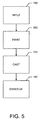
- Fig. 5 shows a flowchart of exemplary steps in carrying out the methods described herein in whole or in part.
- the desired dimensions of the airfoil 100 or other type of turbine component 110 may be input into the additive manufacturing system.
- the additive manufacturing system may print or otherwise produce the core 120, the combined mold and core 130, the outer mold 140, or other type of mold and the like in the additive manufacturing process.
- the core 120 may be used in a conventional investment casting process and the like to create the airfoil 100 and/or the metallic material may be poured or otherwise casted about the combined mold and core 130 so as to create the airfoil 100.
- the core 120 and/or the combined mold and core 130 may be dissolved via water and the like from the airfoil 100. Dissolving the core 130 thus creates the cooling chambers 80 and other types of internal geometries within the airfoil 100.
- the outer mold 140 may be dissolved as well or may be otherwise stripped away.
- the airfoil 100 may now be substantially ready for use and/or further processing.
- the methods steps described herein are not exclusive. Other or different steps may be used in any desired order.
- the methods and systems described herein thus provide for the production of the airfoil 100, other types of turbine components 110, and other components in a fast and efficient manner.
- the airfoil 100 may have advanced and effective internal cooling geometries formed herein.
- the water soluble ceramic material may be used for the three-dimensional printing of the core 120 and the like so as to avoid the use of hazardous chemicals generally required for leaching. Any suitable ceramic material may be used for three-dimensional printing of the core 120 and/or the combined mold and core 130.
- the binder jetting processes described herein may be used for three-dimensional printing with any type of ceramic. Other types of additive manufacturing processes may be used herein.
Landscapes
- Engineering & Computer Science (AREA)
- Mechanical Engineering (AREA)
- Chemical & Material Sciences (AREA)
- Materials Engineering (AREA)
- Molds, Cores, And Manufacturing Methods Thereof (AREA)
- Turbine Rotor Nozzle Sealing (AREA)
Description
- The present application and the resultant patent relate generally to gas turbine engines and more particularly relate to three-dimensional manufacturing methods and systems for complex hot gas path turbine components and the like with improved cooling capacity.
- Gas turbine engine components such as buckets, nozzles, and other components in the hot gas path, may be produced in an investment casting process. Generally described, a ceramic core and shell may be produced separately. The ceramic core may be produced by pouring a ceramic slurry into a metal die and solidifying the ceramic material. The ceramic core then may be encased in wax and a ceramic shell may be formed around the wax pattern. The wax that encases the ceramic core then may be removed to form a ceramic mold in which a metallic component may be cast. Once the metallic component is cooled, the shell materials may be stripped away and the ceramic core may be leached away to form the finished product. Other types of component casting methods may be used.
- Components having complex geometry such as internal passages and voids therein may be difficult to cast or otherwise created. For example, such complex geometries may include buckets and nozzles with internal airflow passages for cooling. The tooling used for the manufacture of such parts may be expensive and time consuming to create. Moreover, the chemicals used to leach away the ceramic material may be toxic and hazardous to use.
- The present application and the resultant patent thus provide a method of producing a component. The method may include the steps of creating a dissolvable ceramic material mold in an additive manufacturing process, casting a metallic material in the dissolvable ceramic material mold, creating the component, and dissolving the dissolvable ceramic material. The component may be a turbine component.
- The present application and the resultant patent further provide a combined core and mold for creating a turbine component. The combined core and mold may include an inner core and an outer mold. The inner core and the outer mold may define a sidewall and a number of inner ribs therebetween. The inner core and the outer mold may be made from a dissolvable ceramic material suitable for an additive manufacturing process. The turbine component may be an airfoil or other type of hot gas path component.
- The present application and the resultant patent further provide a method of producing a turbine airfoil with a number of internal channels. The method may include the steps of creating a combined core and mold of a dissolvable ceramic material in an additive manufacturing process, casting a metallic material in the combined core and mold, creating the turbine airfoil, and dissolving the dissolvable ceramic material within the internal channels.
- These and other features and improvements of the present application and the resultant patent will become apparent to one of ordinary skill in the art upon review of the following detailed description when taken in conjunction with the several drawings and the appended claims.
-
-
Fig.1 is a schematic diagram of a gas turbine engine showing a compressor, a combustor, a turbine, and a load. -
Fig. 2 is a sectional view of an airfoil that may be used with the gas turbine engine ofFig. 1 . -
Fig. 3 is a sectional view of a core that may be used to manufacture the airfoil ofFig. 2 . -
Fig. 4 is a sectional view of a combined core and mold that may be used to manufacture the airfoil ofFig. 2 . -
Fig. 5 is a flowchart showing exemplary steps in creating the core ofFig. 3 and/or the combined core and mold ofFig. 4 . - Referring now to the drawings, in which like numerals refer to like elements throughout the several views,
Fig. 1 shows a schematic view ofgas turbine engine 10 as may be used herein. Thegas turbine engine 10 may include acompressor 15. Thecompressor 15 compresses an incoming flow ofair 20. Thecompressor 15 delivers the compressed flow ofair 20 to acombustor 25. Thecombustor 25 mixes the compressed flow ofair 20 with a compressed flow offuel 30 and ignites the mixture to create a flow ofcombustion gases 35. Although only asingle combustor 25 is shown, thegas turbine engine 10 may include any number ofcombustors 25. The flow ofcombustion gases 35 is in turn delivered to aturbine 40. The flow ofcombustion gases 35 drives theturbine 40 so as to produce mechanical work. The mechanical work produced in theturbine 40 drives thecompressor 15 via ashaft 45 and anexternal load 50 such as an electrical generator and the like. - The
gas turbine engine 10 may use natural gas, various types of syngas, liquid fuels, and/or other types of fuels and blends thereof. Thegas turbine engine 10 may be any one of a number of different gas turbine engines offered by General Electric Company of Schenectady, New York, including, but not limited to, those such as a 7 or a 9 series heavy duty gas turbine engine and the like. Thegas turbine engine 10 may have different configurations and may use other types of components. Other types of gas turbine engines also may be used herein. Multiple gas turbine engines, other types of turbines, and other types of power generation equipment also may be used herein together. -
Fig. 2 shows an example of a turbine airfoil 55 that may be used with thegas turbine engine 10 ofFig. 1 . The airfoil 55 may include amain sidewall 60. Themain sidewall 60 may extend from a leadingedge 65 to atrailing edge 70. Within themain sidewall 60, the airfoil 55 may have a number ofinternal ribs 75. Themain sidewall 60 and theinternal ribs 75 may define any number ofchannels 80 therein. Thechannels 80 may permit a flow of a fluid such as air to provide cooling to the airfoil 55. A number ofcrossover holes 85 also may extend through theinternal ribs 75 and between thechannels 80. The airfoil 55 is described herein for the purpose of example only. Many different types of airfoils with many different internal configurations may be used. Likewise, many different types of hot gas path components and other types of turbine components may be used. - As described above, the airfoil 55 traditionally has been produced in an investment casting process. Specifically, the
channels 80 may be formed via a ceramic core while thesidewall 60 may be formed within an outer ceramic mold. Certain shapes and configurations, however, may be difficult to manufacture in such an investment casting process. - Instead of the investment casting process and the like, an airfoil 100 or other type of turbine component 110 as may be described herein may be manufactured in an additive manufacturing system. Such an additive manufacturing system may include a three-dimensional printing process, an additive printing process, and the like. Examples of such systems and processes may include extrusion base techniques, jetting, selective laser sintering, powder/binder jetting, electron beam melting, stereo-lithographic processes, and the like. Specifically, binder jetting is an additive manufacturing process in which a liquid binding agent is selectively deposited to join powder particles. Layers of material then may be bonded to form an object. The object thus develops through the layering of the powder and the binding. Binder jetting may be similar to traditional paper printing in that the binder functions like the ink as it moves across the layers of powder which function like paper to form the final product. Other types of manufacturing processes may be used herein.
- Such a binder jetting process may be used with ceramic materials and the like. More particularly, the process may be used with water soluble ceramic materials. For example, a suitable material may include about sixty to seventy weight percent (60 to 70%) alumina (AL2O3) flour, about fifteen to twenty-five weight percent (15 to 25%) zircon (ZrSiO4) flour, about five to fifteen weight percent (5 to 15%) sodium hydrogen phosphate (Na2HPO4), and about five weight percent (5%) of cane sugar. More preferably, the ceramic core may contain about sixty-five weight percent (65%) of alumina flour, about twenty weight percent (20%) of zircon flour, about ten weight percent (10%) of sodium hydrogen phosphate, and about five weight percent (5%) of cane sugar. In this composition, the alumina and the zircon may be used primarily as fillers. The sodium hydrogen phosphate may be a binding agent. The cane sugar may improve the surface smoothness and the wet strength of the resultant water-soluble ceramic core. Other types of ceramics, water soluble ceramics, and other materials may be used herein.
-
Fig. 3 shows an example of a core 120 that may be used to create the airfoil 100 or other type of turbine component 110 and the like. As is shown, thecore 120 corresponds to thechannels 80 and crossover holes 85 with the space in-between corresponding to theinternal ribs 75. Thecore 120 may be made from a ceramic material and more specifically, may be made from a water soluble ceramic material similar to that described above and the like. Other types of materials may be used herein. Thecore 120 may be made from an additive manufacturing process such as the binder jetting process described above and the like. Other types of additive manufacturing processes including but not limited to those described above also may be used herein. Other components and other configurations may be used herein. - Once produced, the
core 120 then may be used in a conventional investment casting process and the like so as to form the outer mold or other type of structure. Alternatively, a combined core andmold 130 may be created as is shown inFig. 4 . The combined core andmold 130 may include thecore 120 substantially as described above and anouter mold 140. Thesidewall 60 and other components of the airfoil 100 may be defined between the core 120 and theouter mold 140. Both thecore 120 and theouter mold 140 may be created at the same time in the additive manufacturing processes described herein as opposed to the separate structures from in the traditional manufacturing processes. Again, a ceramic material and more preferably a water soluble ceramic material may be used herein. Other components and other configurations may be used herein. -
Fig. 5 shows a flowchart of exemplary steps in carrying out the methods described herein in whole or in part. Atstep 150, the desired dimensions of the airfoil 100 or other type of turbine component 110 may be input into the additive manufacturing system. Atstep 160, the additive manufacturing system may print or otherwise produce thecore 120, the combined mold andcore 130, theouter mold 140, or other type of mold and the like in the additive manufacturing process. Atstep 170, thecore 120 may be used in a conventional investment casting process and the like to create the airfoil 100 and/or the metallic material may be poured or otherwise casted about the combined mold andcore 130 so as to create the airfoil 100. Atstep 180, thecore 120 and/or the combined mold andcore 130 may be dissolved via water and the like from the airfoil 100. Dissolving thecore 130 thus creates the coolingchambers 80 and other types of internal geometries within the airfoil 100. Theouter mold 140 may be dissolved as well or may be otherwise stripped away. The airfoil 100 may now be substantially ready for use and/or further processing. The methods steps described herein are not exclusive. Other or different steps may be used in any desired order. - The methods and systems described herein thus provide for the production of the airfoil 100, other types of turbine components 110, and other components in a fast and efficient manner. Moreover, the airfoil 100 may have advanced and effective internal cooling geometries formed herein. Further, the water soluble ceramic material may be used for the three-dimensional printing of the
core 120 and the like so as to avoid the use of hazardous chemicals generally required for leaching. Any suitable ceramic material may be used for three-dimensional printing of thecore 120 and/or the combined mold andcore 130. The binder jetting processes described herein may be used for three-dimensional printing with any type of ceramic. Other types of additive manufacturing processes may be used herein. - It should be apparent that the foregoing relates only to certain embodiments of the present application and the resultant patent. Numerous changes and modifications may be made herein by one of ordinary skill in the art without departing from the general spirit and scope of the invention as defined by the following claims and the equivalents thereof.
Claims (15)
- A method of producing a component (110), comprising:creating a dissolvable ceramic material mold (120, 130) in an additive manufacturing process;casting a metallic material in the dissolvable ceramic material mold (120, 130);creating the component (110); anddissolving the dissolvable ceramic material.
- The method of claim 1, wherein the component (110) produced herein comprises an airfoil (100) with internal cooling channels (80).
- The method of claim 1, wherein the step of creating a dissolvable ceramic mold (120, 130) comprises creating a dissolvable ceramic core (120).
- The method of claim 3, wherein the step of casting a metallic material in the dissolvable ceramic mold (120, 130) comprises casting the metallic material about the dissolvable ceramic core (120).
- The method of claim 3, wherein the step of dissolving the dissolvable ceramic material comprises dissolving the dissolvable ceramic core (120) with water.
- The method of claim 5, wherein the step of dissolving the dissolvable ceramic core (120) comprises creating a cooling channel (80) in the component (110).
- The method of claim 1, wherein the step of creating a dissolvable ceramic mold (120, 130) comprises creating a dissolvable ceramic combined core and mold (130).
- The method of claim 7, wherein the step of casting a metallic material in the dissolvable ceramic mold (120, 130) comprises casting the metallic material about the dissolvable ceramic combined core and mold (130).
- The method of claim 7, wherein the step of dissolving the dissolvable ceramic material comprises dissolving the dissolvable ceramic combined core and mold (130) with water.
- The method of claim 9, wherein the step of dissolving dissolvable ceramic combined core and mold (130) comprises creating a cooling channel (80) and a sidewall (60) in the component.
- The method of claim 7, wherein the step of creating the dissolvable ceramic combined core and mold (130) comprises creating the core (120) and the mold (140) together in the additive manufacturing process.
- The method of claim 1, wherein the step of creating a dissolvable ceramic material mold (120, 130) in an additive manufacturing process comprises a binder jetting process.
- The method of claim 1, wherein the step of creating a dissolvable ceramic material mold (120, 130) in an additive manufacturing process comprises printing a dissolvable ceramic material with alumina flour, zircon flour, sodium hydrogen phosphate, and/or sugar.
- A combined core and mold (130) for creating a turbine component (110), comprising:an inner core (120); andan outer mold (140);the inner core (120) and the outer mold (140) defining a sidewall (60) and a plurality of inner ribs (75) therebetween;the inner core (120) and the outer mold (140) comprising a dissolvable ceramic material suitable for an additive manufacturing process.
- The combined core and mold (130) of claim 14, wherein the turbine component (110) comprises an airfoil (100) with internal cooling channels (80) defined by the sidewall (60) and the plurality of internal ribs (75).
Applications Claiming Priority (1)
| Application Number | Priority Date | Filing Date | Title |
|---|---|---|---|
| US14/794,839 US10029299B2 (en) | 2015-07-09 | 2015-07-09 | Three-dimensional manufacturing methods and systems for turbine components |
Publications (2)
| Publication Number | Publication Date |
|---|---|
| EP3135398A1 true EP3135398A1 (en) | 2017-03-01 |
| EP3135398B1 EP3135398B1 (en) | 2022-02-23 |
Family
ID=56372821
Family Applications (1)
| Application Number | Title | Priority Date | Filing Date |
|---|---|---|---|
| EP16178546.4A Active EP3135398B1 (en) | 2015-07-09 | 2016-07-08 | Three-dimensional manufacturing methods for turbine components |
Country Status (4)
| Country | Link |
|---|---|
| US (1) | US10029299B2 (en) |
| EP (1) | EP3135398B1 (en) |
| JP (1) | JP7086515B2 (en) |
| CN (1) | CN106334781A (en) |
Families Citing this family (15)
| Publication number | Priority date | Publication date | Assignee | Title |
|---|---|---|---|---|
| US10717130B2 (en) * | 2017-02-22 | 2020-07-21 | General Electric Company | Method of manufacturing turbine airfoil and tip component thereof |
| JP7358340B2 (en) | 2017-05-26 | 2023-10-10 | インフィニット・マテリアル・ソリューションズ,エルエルシー | Water-soluble polymer composition |
| US11173542B2 (en) | 2017-06-28 | 2021-11-16 | General Electric Company | Additively manufactured casting core-shell mold and ceramic shell with variable thermal properties |
| US11192172B2 (en) | 2017-06-28 | 2021-12-07 | General Electric Company | Additively manufactured interlocking casting core structure with ceramic shell |
| US10391549B2 (en) * | 2017-06-28 | 2019-08-27 | General Electric Company | Additively manufactured casting core-shell hybrid mold and ceramic shell |
| US10974312B2 (en) | 2017-06-28 | 2021-04-13 | General Electric Company | Additively manufactured casting core-shell mold with integrated filter and ceramic shell |
| US10391670B2 (en) * | 2017-06-28 | 2019-08-27 | General Electric Company | Additively manufactured integrated casting core structure with ceramic shell |
| US11066335B2 (en) | 2017-09-06 | 2021-07-20 | General Electric Company | Articles for creating hollow structures in ceramic matrix composites |
| US10946914B2 (en) | 2017-12-13 | 2021-03-16 | Adamant Conceptions Inc. | Chain assembly and a bicycle lock manufactured therefrom |
| US12371581B2 (en) | 2020-03-25 | 2025-07-29 | Infinite Material Solutions, Llc | High performance water soluble polymer compositions |
| CN116600959A (en) * | 2020-12-14 | 2023-08-15 | 赛多利斯史泰迪北美股份有限公司 | Rapid Dissolving Cavity Forming Structures for Injection Molded Structures |
| KR102453353B1 (en) * | 2021-05-26 | 2022-10-11 | 한양대학교 산학협력단 | Method of manufacturing a micro-drill and a micro-drill manufactured by the method |
| GB202109321D0 (en) * | 2021-06-29 | 2021-08-11 | Rolls Royce Plc | Manufacturing process for blades of a turbo machine and blades for a turbo machine |
| JP7644693B2 (en) * | 2021-09-29 | 2025-03-12 | 太平洋セメント株式会社 | Mold, manufacturing method thereof and casting method |
| CN117383916B (en) * | 2023-09-21 | 2025-07-29 | 华中科技大学 | Soluble ceramic core, preparation method and application |
Citations (1)
| Publication number | Priority date | Publication date | Assignee | Title |
|---|---|---|---|---|
| DE102013003303A1 (en) * | 2013-02-28 | 2014-08-28 | FluidSolids AG | Process for producing a molded part with a water-soluble casting mold and material system for its production |
Family Cites Families (32)
| Publication number | Priority date | Publication date | Assignee | Title |
|---|---|---|---|---|
| US5204055A (en) * | 1989-12-08 | 1993-04-20 | Massachusetts Institute Of Technology | Three-dimensional printing techniques |
| US6024787A (en) | 1998-06-05 | 2000-02-15 | Industrial Technology Research Institute | Water soluble ceramic core for use in die casting, gravity and investment casting of aluminum alloys |
| CA2351322C (en) * | 1998-11-20 | 2008-07-29 | Rolls-Royce Corporation | Method and apparatus for production of a cast component |
| US20010050031A1 (en) * | 2000-04-14 | 2001-12-13 | Z Corporation | Compositions for three-dimensional printing of solid objects |
| US6558119B2 (en) | 2001-05-29 | 2003-05-06 | General Electric Company | Turbine airfoil with separately formed tip and method for manufacture and repair thereof |
| US7087109B2 (en) * | 2002-09-25 | 2006-08-08 | Z Corporation | Three dimensional printing material system and method |
| US7278829B2 (en) | 2005-02-09 | 2007-10-09 | General Electric Company | Gas turbine blade having a monocrystalline airfoil with a repair squealer tip, and repair method |
| US20060243421A1 (en) * | 2005-04-29 | 2006-11-02 | United States Of America, Represented By Secretary Of The U.S. Army | Soluble casting core for metal matrix composite components and method of producing thereof |
| US7282681B2 (en) | 2005-05-05 | 2007-10-16 | General Electric Company | Microwave fabrication of airfoil tips |
| GR1005620B (en) | 2006-05-09 | 2007-09-03 | Improved dry powder inhaler | |
| US7938168B2 (en) | 2006-12-06 | 2011-05-10 | General Electric Company | Ceramic cores, methods of manufacture thereof and articles manufactured from the same |
| US7624787B2 (en) | 2006-12-06 | 2009-12-01 | General Electric Company | Disposable insert, and use thereof in a method for manufacturing an airfoil |
| US8726501B2 (en) | 2009-08-31 | 2014-05-20 | General Electric Company | Method of welding single crystal turbine blade tips with an oxidation-resistant filler material |
| US9272324B2 (en) * | 2009-12-08 | 2016-03-01 | Siemens Energy, Inc. | Investment casting process for hollow components |
| CN101992268B (en) * | 2010-11-20 | 2012-09-05 | 沈阳工业大学 | Preparation process of high-temperature alloy multigang hollow turbine blade |
| CN102039375B (en) * | 2010-11-20 | 2013-03-13 | 沈阳工业大学 | Method for quickly manufacturing high-temperature alloy hollow blade casting |
| US9033652B2 (en) | 2011-09-30 | 2015-05-19 | General Electric Company | Method and apparatus for cooling gas turbine rotor blades |
| US8960215B2 (en) | 2012-08-02 | 2015-02-24 | General Electric Company | Leak plugging in components with fluid flow passages |
| US9475119B2 (en) | 2012-08-03 | 2016-10-25 | General Electric Company | Molded articles |
| US9656321B2 (en) | 2013-05-15 | 2017-05-23 | General Electric Company | Casting method, cast article and casting system |
| CN103360079B (en) * | 2013-07-10 | 2015-04-29 | 西安交通大学 | Method for customizing core and shell of integrated ceramic mold of hollow turbine blade |
| US9765623B2 (en) | 2013-07-23 | 2017-09-19 | General Electric Company | Methods for modifying cooling holes with recess-shaped modifications |
| US9415468B2 (en) | 2013-08-20 | 2016-08-16 | General Electric Company | Method for manufacturing an airfoil |
| US20150064019A1 (en) | 2013-08-30 | 2015-03-05 | General Electric Company | Gas Turbine Components with Porous Cooling Features |
| US9482249B2 (en) | 2013-09-09 | 2016-11-01 | General Electric Company | Three-dimensional printing process, swirling device and thermal management process |
| US9289917B2 (en) | 2013-10-01 | 2016-03-22 | General Electric Company | Method for 3-D printing a pattern for the surface of a turbine shroud |
| US10539041B2 (en) | 2013-10-22 | 2020-01-21 | General Electric Company | Cooled article and method of forming a cooled article |
| US9416667B2 (en) | 2013-11-22 | 2016-08-16 | General Electric Company | Modified turbine components with internally cooled supplemental elements and methods for making the same |
| US20150159257A1 (en) | 2013-12-05 | 2015-06-11 | General Electric Company | Coating method, coating system, and coated article |
| US20160332373A1 (en) * | 2013-12-23 | 2016-11-17 | The Exone Company | Methods and Systems for Three-Dimensional Printing Utilizing Multiple Binder Fluids |
| US9435211B2 (en) * | 2014-05-09 | 2016-09-06 | United Technologies Corporation | Method for forming components using additive manufacturing and re-melt |
| CN104493081B (en) * | 2014-12-09 | 2016-07-06 | 南京航空航天大学 | Wax injection mould and method for fast mfg thereof for hollow turbine vane model casting |
-
2015
- 2015-07-09 US US14/794,839 patent/US10029299B2/en active Active
-
2016
- 2016-07-01 JP JP2016131192A patent/JP7086515B2/en active Active
- 2016-07-08 CN CN201610535180.2A patent/CN106334781A/en active Pending
- 2016-07-08 EP EP16178546.4A patent/EP3135398B1/en active Active
Patent Citations (1)
| Publication number | Priority date | Publication date | Assignee | Title |
|---|---|---|---|---|
| DE102013003303A1 (en) * | 2013-02-28 | 2014-08-28 | FluidSolids AG | Process for producing a molded part with a water-soluble casting mold and material system for its production |
Non-Patent Citations (5)
| Title |
|---|
| BASSOLI E ET AL: "3D printing technique applied to rapid casting", RAPID PROTOTYPING JOURNAL, MCB UNIVERSITY PRESS, BRADFORD, GB, vol. 13, no. 3, 1 January 2007 (2007-01-01), pages 148 - 155, XP002695629, ISSN: 1355-2546, DOI: 10.1108/13552540710750898 * |
| DRUSCHITZ A ET AL: "Additive Manufacturing Supports the Production of Complex Caszings", SHAPE CASTING: 5TH INTERNATIONAL SYMPOSIUM 2014,, 1 January 2014 (2014-01-01), pages 51 - 57, XP009192302 * |
| HAIHUA WU, DICHEN LI, NANNAN GUO: "Fabrication of integral ceramic mold for investment casting of hollow turbine blade based on stereolithography", RAPID PROTOTYPING JOURNAL, vol. 15, no. 4, 2009, XP002763962 * |
| KOLTYGIN A V ET AL: "Development of a substitute for Z cast molding sand used on installations of 3D printing for obtaining aluminum, magnesium, and iron casting", RUSSIAN JOURNAL OF NON-FERROUS METALS, ALLERTON PRESS, INC, HEIDELBERG, vol. 53, no. 1, 7 March 2012 (2012-03-07), pages 38 - 41, XP035024572, ISSN: 1934-970X, DOI: 10.3103/S1067821212010129 * |
| SAROJRANI PATTNAIK ET AL: "A review of rapid prototyping integrated investment casting processes", PROCEEDINGS OF THE INSTITUTION OF MECHANICAL ENGINEERS, PART L: JOURNAL OF MATERIALS: DESIGN AND APPLICATIONS,, vol. 228, 1 January 2014 (2014-01-01), pages 249 - 277, XP009192299 * |
Also Published As
| Publication number | Publication date |
|---|---|
| CN106334781A (en) | 2017-01-18 |
| JP7086515B2 (en) | 2022-06-20 |
| US20170008072A1 (en) | 2017-01-12 |
| JP2017020504A (en) | 2017-01-26 |
| US10029299B2 (en) | 2018-07-24 |
| EP3135398B1 (en) | 2022-02-23 |
Similar Documents
| Publication | Publication Date | Title |
|---|---|---|
| US10029299B2 (en) | Three-dimensional manufacturing methods and systems for turbine components | |
| EP2841701B1 (en) | Gas turbine engine airfoil impingement cooling | |
| JP5318372B2 (en) | Method of manufacturing metal composite foam component and preform for metal composite component | |
| EP1634665B1 (en) | Composite core for use in precision investment casting | |
| US9421606B2 (en) | Casting cores and manufacture methods | |
| US20100025001A1 (en) | Methods for fabricating gas turbine components using an integrated disposable core and shell die | |
| EP3929402A1 (en) | Gas turbine engine airfoil geometries and cores for manufacturing process | |
| US10766065B2 (en) | Method and assembly for a multiple component core assembly | |
| US20180099329A1 (en) | Metal Castings Including Integral Separately Fabricated Components | |
| EP3238860B1 (en) | Method and assembly for forming components using a jacketed core | |
| JP6924063B2 (en) | Methods and assemblies for forming parts using jacketed cores | |
| EP3210693B1 (en) | Manufacturing process of a component formed around a first metal component using hot isostatic pressing | |
| EP3059045A1 (en) | Method of processing unfinished surfaces | |
| US10279388B2 (en) | Methods for forming components using a jacketed mold pattern | |
| EP3433036B1 (en) | Method of manufacturing a hybridized core with protruding cast in cooling features for investment casting | |
| EP3431207B1 (en) | Linkage of composite core features | |
| JP6196472B2 (en) | Precision casting core and manufacturing method thereof, precision casting mold | |
| JP2014231077A (en) | Core for precision casting, production method therefor, and mold for precision casting |
Legal Events
| Date | Code | Title | Description |
|---|---|---|---|
| PUAI | Public reference made under article 153(3) epc to a published international application that has entered the european phase |
Free format text: ORIGINAL CODE: 0009012 |
|
| STAA | Information on the status of an ep patent application or granted ep patent |
Free format text: STATUS: THE APPLICATION HAS BEEN PUBLISHED |
|
| AK | Designated contracting states |
Kind code of ref document: A1 Designated state(s): AL AT BE BG CH CY CZ DE DK EE ES FI FR GB GR HR HU IE IS IT LI LT LU LV MC MK MT NL NO PL PT RO RS SE SI SK SM TR |
|
| AX | Request for extension of the european patent |
Extension state: BA ME |
|
| STAA | Information on the status of an ep patent application or granted ep patent |
Free format text: STATUS: REQUEST FOR EXAMINATION WAS MADE |
|
| 17P | Request for examination filed |
Effective date: 20170901 |
|
| RBV | Designated contracting states (corrected) |
Designated state(s): AL AT BE BG CH CY CZ DE DK EE ES FI FR GB GR HR HU IE IS IT LI LT LU LV MC MK MT NL NO PL PT RO RS SE SI SK SM TR |
|
| STAA | Information on the status of an ep patent application or granted ep patent |
Free format text: STATUS: EXAMINATION IS IN PROGRESS |
|
| 17Q | First examination report despatched |
Effective date: 20180102 |
|
| GRAP | Despatch of communication of intention to grant a patent |
Free format text: ORIGINAL CODE: EPIDOSNIGR1 |
|
| STAA | Information on the status of an ep patent application or granted ep patent |
Free format text: STATUS: GRANT OF PATENT IS INTENDED |
|
| INTG | Intention to grant announced |
Effective date: 20211006 |
|
| GRAS | Grant fee paid |
Free format text: ORIGINAL CODE: EPIDOSNIGR3 |
|
| GRAA | (expected) grant |
Free format text: ORIGINAL CODE: 0009210 |
|
| STAA | Information on the status of an ep patent application or granted ep patent |
Free format text: STATUS: THE PATENT HAS BEEN GRANTED |
|
| AK | Designated contracting states |
Kind code of ref document: B1 Designated state(s): AL AT BE BG CH CY CZ DE DK EE ES FI FR GB GR HR HU IE IS IT LI LT LU LV MC MK MT NL NO PL PT RO RS SE SI SK SM TR |
|
| REG | Reference to a national code |
Ref country code: GB Ref legal event code: FG4D |
|
| REG | Reference to a national code |
Ref country code: CH Ref legal event code: EP |
|
| REG | Reference to a national code |
Ref country code: DE Ref legal event code: R096 Ref document number: 602016069299 Country of ref document: DE |
|
| REG | Reference to a national code |
Ref country code: AT Ref legal event code: REF Ref document number: 1470034 Country of ref document: AT Kind code of ref document: T Effective date: 20220315 |
|
| REG | Reference to a national code |
Ref country code: IE Ref legal event code: FG4D |
|
| REG | Reference to a national code |
Ref country code: LT Ref legal event code: MG9D |
|
| REG | Reference to a national code |
Ref country code: NL Ref legal event code: MP Effective date: 20220223 |
|
| REG | Reference to a national code |
Ref country code: AT Ref legal event code: MK05 Ref document number: 1470034 Country of ref document: AT Kind code of ref document: T Effective date: 20220223 |
|
| PG25 | Lapsed in a contracting state [announced via postgrant information from national office to epo] |
Ref country code: SE Free format text: LAPSE BECAUSE OF FAILURE TO SUBMIT A TRANSLATION OF THE DESCRIPTION OR TO PAY THE FEE WITHIN THE PRESCRIBED TIME-LIMIT Effective date: 20220223 Ref country code: RS Free format text: LAPSE BECAUSE OF FAILURE TO SUBMIT A TRANSLATION OF THE DESCRIPTION OR TO PAY THE FEE WITHIN THE PRESCRIBED TIME-LIMIT Effective date: 20220223 Ref country code: PT Free format text: LAPSE BECAUSE OF FAILURE TO SUBMIT A TRANSLATION OF THE DESCRIPTION OR TO PAY THE FEE WITHIN THE PRESCRIBED TIME-LIMIT Effective date: 20220623 Ref country code: NO Free format text: LAPSE BECAUSE OF FAILURE TO SUBMIT A TRANSLATION OF THE DESCRIPTION OR TO PAY THE FEE WITHIN THE PRESCRIBED TIME-LIMIT Effective date: 20220523 Ref country code: NL Free format text: LAPSE BECAUSE OF FAILURE TO SUBMIT A TRANSLATION OF THE DESCRIPTION OR TO PAY THE FEE WITHIN THE PRESCRIBED TIME-LIMIT Effective date: 20220223 Ref country code: LT Free format text: LAPSE BECAUSE OF FAILURE TO SUBMIT A TRANSLATION OF THE DESCRIPTION OR TO PAY THE FEE WITHIN THE PRESCRIBED TIME-LIMIT Effective date: 20220223 Ref country code: HR Free format text: LAPSE BECAUSE OF FAILURE TO SUBMIT A TRANSLATION OF THE DESCRIPTION OR TO PAY THE FEE WITHIN THE PRESCRIBED TIME-LIMIT Effective date: 20220223 Ref country code: ES Free format text: LAPSE BECAUSE OF FAILURE TO SUBMIT A TRANSLATION OF THE DESCRIPTION OR TO PAY THE FEE WITHIN THE PRESCRIBED TIME-LIMIT Effective date: 20220223 Ref country code: BG Free format text: LAPSE BECAUSE OF FAILURE TO SUBMIT A TRANSLATION OF THE DESCRIPTION OR TO PAY THE FEE WITHIN THE PRESCRIBED TIME-LIMIT Effective date: 20220523 |
|
| PG25 | Lapsed in a contracting state [announced via postgrant information from national office to epo] |
Ref country code: PL Free format text: LAPSE BECAUSE OF FAILURE TO SUBMIT A TRANSLATION OF THE DESCRIPTION OR TO PAY THE FEE WITHIN THE PRESCRIBED TIME-LIMIT Effective date: 20220223 Ref country code: LV Free format text: LAPSE BECAUSE OF FAILURE TO SUBMIT A TRANSLATION OF THE DESCRIPTION OR TO PAY THE FEE WITHIN THE PRESCRIBED TIME-LIMIT Effective date: 20220223 Ref country code: GR Free format text: LAPSE BECAUSE OF FAILURE TO SUBMIT A TRANSLATION OF THE DESCRIPTION OR TO PAY THE FEE WITHIN THE PRESCRIBED TIME-LIMIT Effective date: 20220524 Ref country code: FI Free format text: LAPSE BECAUSE OF FAILURE TO SUBMIT A TRANSLATION OF THE DESCRIPTION OR TO PAY THE FEE WITHIN THE PRESCRIBED TIME-LIMIT Effective date: 20220223 Ref country code: AT Free format text: LAPSE BECAUSE OF FAILURE TO SUBMIT A TRANSLATION OF THE DESCRIPTION OR TO PAY THE FEE WITHIN THE PRESCRIBED TIME-LIMIT Effective date: 20220223 |
|
| PG25 | Lapsed in a contracting state [announced via postgrant information from national office to epo] |
Ref country code: IS Free format text: LAPSE BECAUSE OF FAILURE TO SUBMIT A TRANSLATION OF THE DESCRIPTION OR TO PAY THE FEE WITHIN THE PRESCRIBED TIME-LIMIT Effective date: 20220623 |
|
| PG25 | Lapsed in a contracting state [announced via postgrant information from national office to epo] |
Ref country code: SM Free format text: LAPSE BECAUSE OF FAILURE TO SUBMIT A TRANSLATION OF THE DESCRIPTION OR TO PAY THE FEE WITHIN THE PRESCRIBED TIME-LIMIT Effective date: 20220223 Ref country code: SK Free format text: LAPSE BECAUSE OF FAILURE TO SUBMIT A TRANSLATION OF THE DESCRIPTION OR TO PAY THE FEE WITHIN THE PRESCRIBED TIME-LIMIT Effective date: 20220223 Ref country code: RO Free format text: LAPSE BECAUSE OF FAILURE TO SUBMIT A TRANSLATION OF THE DESCRIPTION OR TO PAY THE FEE WITHIN THE PRESCRIBED TIME-LIMIT Effective date: 20220223 Ref country code: EE Free format text: LAPSE BECAUSE OF FAILURE TO SUBMIT A TRANSLATION OF THE DESCRIPTION OR TO PAY THE FEE WITHIN THE PRESCRIBED TIME-LIMIT Effective date: 20220223 Ref country code: DK Free format text: LAPSE BECAUSE OF FAILURE TO SUBMIT A TRANSLATION OF THE DESCRIPTION OR TO PAY THE FEE WITHIN THE PRESCRIBED TIME-LIMIT Effective date: 20220223 Ref country code: CZ Free format text: LAPSE BECAUSE OF FAILURE TO SUBMIT A TRANSLATION OF THE DESCRIPTION OR TO PAY THE FEE WITHIN THE PRESCRIBED TIME-LIMIT Effective date: 20220223 |
|
| REG | Reference to a national code |
Ref country code: DE Ref legal event code: R097 Ref document number: 602016069299 Country of ref document: DE |
|
| PG25 | Lapsed in a contracting state [announced via postgrant information from national office to epo] |
Ref country code: AL Free format text: LAPSE BECAUSE OF FAILURE TO SUBMIT A TRANSLATION OF THE DESCRIPTION OR TO PAY THE FEE WITHIN THE PRESCRIBED TIME-LIMIT Effective date: 20220223 |
|
| PLBE | No opposition filed within time limit |
Free format text: ORIGINAL CODE: 0009261 |
|
| STAA | Information on the status of an ep patent application or granted ep patent |
Free format text: STATUS: NO OPPOSITION FILED WITHIN TIME LIMIT |
|
| 26N | No opposition filed |
Effective date: 20221124 |
|
| PG25 | Lapsed in a contracting state [announced via postgrant information from national office to epo] |
Ref country code: SI Free format text: LAPSE BECAUSE OF FAILURE TO SUBMIT A TRANSLATION OF THE DESCRIPTION OR TO PAY THE FEE WITHIN THE PRESCRIBED TIME-LIMIT Effective date: 20220223 Ref country code: MC Free format text: LAPSE BECAUSE OF FAILURE TO SUBMIT A TRANSLATION OF THE DESCRIPTION OR TO PAY THE FEE WITHIN THE PRESCRIBED TIME-LIMIT Effective date: 20220223 |
|
| REG | Reference to a national code |
Ref country code: CH Ref legal event code: PL |
|
| REG | Reference to a national code |
Ref country code: BE Ref legal event code: MM Effective date: 20220731 |
|
| PG25 | Lapsed in a contracting state [announced via postgrant information from national office to epo] |
Ref country code: LU Free format text: LAPSE BECAUSE OF NON-PAYMENT OF DUE FEES Effective date: 20220708 Ref country code: LI Free format text: LAPSE BECAUSE OF NON-PAYMENT OF DUE FEES Effective date: 20220731 Ref country code: CH Free format text: LAPSE BECAUSE OF NON-PAYMENT OF DUE FEES Effective date: 20220731 |
|
| PG25 | Lapsed in a contracting state [announced via postgrant information from national office to epo] |
Ref country code: BE Free format text: LAPSE BECAUSE OF NON-PAYMENT OF DUE FEES Effective date: 20220731 |
|
| PG25 | Lapsed in a contracting state [announced via postgrant information from national office to epo] |
Ref country code: IE Free format text: LAPSE BECAUSE OF NON-PAYMENT OF DUE FEES Effective date: 20220708 |
|
| REG | Reference to a national code |
Ref country code: DE Ref legal event code: R081 Ref document number: 602016069299 Country of ref document: DE Owner name: GENERAL ELECTRIC TECHNOLOGY GMBH, CH Free format text: FORMER OWNER: GENERAL ELECTRIC COMPANY, SCHENECTADY, NY, US |
|
| REG | Reference to a national code |
Ref country code: GB Ref legal event code: 732E Free format text: REGISTERED BETWEEN 20240222 AND 20240228 |
|
| PG25 | Lapsed in a contracting state [announced via postgrant information from national office to epo] |
Ref country code: HU Free format text: LAPSE BECAUSE OF FAILURE TO SUBMIT A TRANSLATION OF THE DESCRIPTION OR TO PAY THE FEE WITHIN THE PRESCRIBED TIME-LIMIT; INVALID AB INITIO Effective date: 20160708 |
|
| PG25 | Lapsed in a contracting state [announced via postgrant information from national office to epo] |
Ref country code: MK Free format text: LAPSE BECAUSE OF FAILURE TO SUBMIT A TRANSLATION OF THE DESCRIPTION OR TO PAY THE FEE WITHIN THE PRESCRIBED TIME-LIMIT Effective date: 20220223 Ref country code: CY Free format text: LAPSE BECAUSE OF FAILURE TO SUBMIT A TRANSLATION OF THE DESCRIPTION OR TO PAY THE FEE WITHIN THE PRESCRIBED TIME-LIMIT Effective date: 20220223 |
|
| PG25 | Lapsed in a contracting state [announced via postgrant information from national office to epo] |
Ref country code: TR Free format text: LAPSE BECAUSE OF FAILURE TO SUBMIT A TRANSLATION OF THE DESCRIPTION OR TO PAY THE FEE WITHIN THE PRESCRIBED TIME-LIMIT Effective date: 20220223 |
|
| PG25 | Lapsed in a contracting state [announced via postgrant information from national office to epo] |
Ref country code: MT Free format text: LAPSE BECAUSE OF FAILURE TO SUBMIT A TRANSLATION OF THE DESCRIPTION OR TO PAY THE FEE WITHIN THE PRESCRIBED TIME-LIMIT Effective date: 20220223 |
|
| PGFP | Annual fee paid to national office [announced via postgrant information from national office to epo] |
Ref country code: GB Payment date: 20250619 Year of fee payment: 10 |
|
| PGFP | Annual fee paid to national office [announced via postgrant information from national office to epo] |
Ref country code: FR Payment date: 20250619 Year of fee payment: 10 |
|
| PGFP | Annual fee paid to national office [announced via postgrant information from national office to epo] |
Ref country code: DE Payment date: 20250620 Year of fee payment: 10 |
|
| PGFP | Annual fee paid to national office [announced via postgrant information from national office to epo] |
Ref country code: IT Payment date: 20250619 Year of fee payment: 10 |