EP3135181A1 - Endoscope imaging unit - Google Patents
Endoscope imaging unit Download PDFInfo
- Publication number
- EP3135181A1 EP3135181A1 EP15861902.3A EP15861902A EP3135181A1 EP 3135181 A1 EP3135181 A1 EP 3135181A1 EP 15861902 A EP15861902 A EP 15861902A EP 3135181 A1 EP3135181 A1 EP 3135181A1
- Authority
- EP
- European Patent Office
- Prior art keywords
- image pickup
- unit
- frame
- lens
- pickup device
- Prior art date
- Legal status (The legal status is an assumption and is not a legal conclusion. Google has not performed a legal analysis and makes no representation as to the accuracy of the status listed.)
- Withdrawn
Links
- 238000003384 imaging method Methods 0.000 title 1
- 239000000853 adhesive Substances 0.000 claims abstract description 79
- 230000001070 adhesive effect Effects 0.000 claims abstract description 79
- 230000003287 optical effect Effects 0.000 claims abstract description 56
- 230000009477 glass transition Effects 0.000 claims abstract description 15
- 239000002184 metal Substances 0.000 claims description 8
- 238000002844 melting Methods 0.000 claims description 3
- 230000008018 melting Effects 0.000 claims description 3
- 230000008878 coupling Effects 0.000 description 24
- 238000010168 coupling process Methods 0.000 description 24
- 238000005859 coupling reaction Methods 0.000 description 24
- 238000010586 diagram Methods 0.000 description 17
- 239000000463 material Substances 0.000 description 10
- 229920005989 resin Polymers 0.000 description 9
- 239000011347 resin Substances 0.000 description 9
- 238000010438 heat treatment Methods 0.000 description 8
- 238000003780 insertion Methods 0.000 description 8
- 230000037431 insertion Effects 0.000 description 8
- 239000000470 constituent Substances 0.000 description 7
- 238000007689 inspection Methods 0.000 description 7
- 239000000758 substrate Substances 0.000 description 6
- 239000002699 waste material Substances 0.000 description 5
- 238000005476 soldering Methods 0.000 description 4
- 239000003822 epoxy resin Substances 0.000 description 3
- 238000005286 illumination Methods 0.000 description 3
- 230000007246 mechanism Effects 0.000 description 3
- 229920000647 polyepoxide Polymers 0.000 description 3
- 238000007789 sealing Methods 0.000 description 3
- 238000004904 shortening Methods 0.000 description 3
- 229920002050 silicone resin Polymers 0.000 description 3
- 238000005219 brazing Methods 0.000 description 2
- 238000005304 joining Methods 0.000 description 2
- 230000007257 malfunction Effects 0.000 description 2
- 238000003860 storage Methods 0.000 description 2
- 230000004888 barrier function Effects 0.000 description 1
- 230000008901 benefit Effects 0.000 description 1
- 238000011109 contamination Methods 0.000 description 1
- 238000005336 cracking Methods 0.000 description 1
- 230000002950 deficient Effects 0.000 description 1
- 238000001035 drying Methods 0.000 description 1
- 238000000034 method Methods 0.000 description 1
- 230000004048 modification Effects 0.000 description 1
- 238000012986 modification Methods 0.000 description 1
- 238000007747 plating Methods 0.000 description 1
- 230000009467 reduction Effects 0.000 description 1
- 230000008439 repair process Effects 0.000 description 1
- 239000013464 silicone adhesive Substances 0.000 description 1
Images




Classifications
-
- A—HUMAN NECESSITIES
- A61—MEDICAL OR VETERINARY SCIENCE; HYGIENE
- A61B—DIAGNOSIS; SURGERY; IDENTIFICATION
- A61B1/00—Instruments for performing medical examinations of the interior of cavities or tubes of the body by visual or photographical inspection, e.g. endoscopes; Illuminating arrangements therefor
- A61B1/00064—Constructional details of the endoscope body
- A61B1/00071—Insertion part of the endoscope body
- A61B1/0008—Insertion part of the endoscope body characterised by distal tip features
- A61B1/00101—Insertion part of the endoscope body characterised by distal tip features the distal tip features being detachable
-
- A—HUMAN NECESSITIES
- A61—MEDICAL OR VETERINARY SCIENCE; HYGIENE
- A61B—DIAGNOSIS; SURGERY; IDENTIFICATION
- A61B1/00—Instruments for performing medical examinations of the interior of cavities or tubes of the body by visual or photographical inspection, e.g. endoscopes; Illuminating arrangements therefor
-
- A—HUMAN NECESSITIES
- A61—MEDICAL OR VETERINARY SCIENCE; HYGIENE
- A61B—DIAGNOSIS; SURGERY; IDENTIFICATION
- A61B1/00—Instruments for performing medical examinations of the interior of cavities or tubes of the body by visual or photographical inspection, e.g. endoscopes; Illuminating arrangements therefor
- A61B1/00064—Constructional details of the endoscope body
- A61B1/00071—Insertion part of the endoscope body
- A61B1/0008—Insertion part of the endoscope body characterised by distal tip features
- A61B1/00096—Optical elements
-
- A—HUMAN NECESSITIES
- A61—MEDICAL OR VETERINARY SCIENCE; HYGIENE
- A61B—DIAGNOSIS; SURGERY; IDENTIFICATION
- A61B1/00—Instruments for performing medical examinations of the interior of cavities or tubes of the body by visual or photographical inspection, e.g. endoscopes; Illuminating arrangements therefor
- A61B1/00163—Optical arrangements
-
- A—HUMAN NECESSITIES
- A61—MEDICAL OR VETERINARY SCIENCE; HYGIENE
- A61B—DIAGNOSIS; SURGERY; IDENTIFICATION
- A61B1/00—Instruments for performing medical examinations of the interior of cavities or tubes of the body by visual or photographical inspection, e.g. endoscopes; Illuminating arrangements therefor
- A61B1/04—Instruments for performing medical examinations of the interior of cavities or tubes of the body by visual or photographical inspection, e.g. endoscopes; Illuminating arrangements therefor combined with photographic or television appliances
- A61B1/05—Instruments for performing medical examinations of the interior of cavities or tubes of the body by visual or photographical inspection, e.g. endoscopes; Illuminating arrangements therefor combined with photographic or television appliances characterised by the image sensor, e.g. camera, being in the distal end portion
-
- G—PHYSICS
- G02—OPTICS
- G02B—OPTICAL ELEMENTS, SYSTEMS OR APPARATUS
- G02B23/00—Telescopes, e.g. binoculars; Periscopes; Instruments for viewing the inside of hollow bodies; Viewfinders; Optical aiming or sighting devices
- G02B23/24—Instruments or systems for viewing the inside of hollow bodies, e.g. fibrescopes
- G02B23/2407—Optical details
- G02B23/2423—Optical details of the distal end
- G02B23/243—Objectives for endoscopes
-
- G—PHYSICS
- G02—OPTICS
- G02B—OPTICAL ELEMENTS, SYSTEMS OR APPARATUS
- G02B23/00—Telescopes, e.g. binoculars; Periscopes; Instruments for viewing the inside of hollow bodies; Viewfinders; Optical aiming or sighting devices
- G02B23/24—Instruments or systems for viewing the inside of hollow bodies, e.g. fibrescopes
- G02B23/2476—Non-optical details, e.g. housings, mountings, supports
- G02B23/2484—Arrangements in relation to a camera or imaging device
-
- G—PHYSICS
- G02—OPTICS
- G02B—OPTICAL ELEMENTS, SYSTEMS OR APPARATUS
- G02B23/00—Telescopes, e.g. binoculars; Periscopes; Instruments for viewing the inside of hollow bodies; Viewfinders; Optical aiming or sighting devices
- G02B23/24—Instruments or systems for viewing the inside of hollow bodies, e.g. fibrescopes
- G02B23/26—Instruments or systems for viewing the inside of hollow bodies, e.g. fibrescopes using light guides
-
- G—PHYSICS
- G02—OPTICS
- G02B—OPTICAL ELEMENTS, SYSTEMS OR APPARATUS
- G02B7/00—Mountings, adjusting means, or light-tight connections, for optical elements
- G02B7/02—Mountings, adjusting means, or light-tight connections, for optical elements for lenses
- G02B7/025—Mountings, adjusting means, or light-tight connections, for optical elements for lenses using glue
-
- H—ELECTRICITY
- H04—ELECTRIC COMMUNICATION TECHNIQUE
- H04N—PICTORIAL COMMUNICATION, e.g. TELEVISION
- H04N23/00—Cameras or camera modules comprising electronic image sensors; Control thereof
- H04N23/50—Constructional details
- H04N23/55—Optical parts specially adapted for electronic image sensors; Mounting thereof
-
- A—HUMAN NECESSITIES
- A61—MEDICAL OR VETERINARY SCIENCE; HYGIENE
- A61B—DIAGNOSIS; SURGERY; IDENTIFICATION
- A61B1/00—Instruments for performing medical examinations of the interior of cavities or tubes of the body by visual or photographical inspection, e.g. endoscopes; Illuminating arrangements therefor
- A61B1/00064—Constructional details of the endoscope body
- A61B1/00105—Constructional details of the endoscope body characterised by modular construction
-
- A—HUMAN NECESSITIES
- A61—MEDICAL OR VETERINARY SCIENCE; HYGIENE
- A61B—DIAGNOSIS; SURGERY; IDENTIFICATION
- A61B1/00—Instruments for performing medical examinations of the interior of cavities or tubes of the body by visual or photographical inspection, e.g. endoscopes; Illuminating arrangements therefor
- A61B1/00163—Optical arrangements
- A61B1/00174—Optical arrangements characterised by the viewing angles
- A61B1/00177—Optical arrangements characterised by the viewing angles for 90 degrees side-viewing
-
- H—ELECTRICITY
- H04—ELECTRIC COMMUNICATION TECHNIQUE
- H04N—PICTORIAL COMMUNICATION, e.g. TELEVISION
- H04N23/00—Cameras or camera modules comprising electronic image sensors; Control thereof
- H04N23/50—Constructional details
- H04N23/555—Constructional details for picking-up images in sites, inaccessible due to their dimensions or hazardous conditions, e.g. endoscopes or borescopes
Definitions
- the present invention relates to an image pickup unit for endoscope including a solid-state image pickup device built in an insertion portion of an endoscope.
- an endoscope has been used in a medical field and an industrial field.
- the endoscope can perform observation, treatment, and the like by inserting an elongated insertion portion into a tube with a small diameter. Reduction in the diameter of the insertion portion and shortening of a rigid portion are demanded in the endoscope in order to improve an insertion property.
- an image pickup unit for endoscope (hereinafter, abbreviated as an image pickup unit) built in a distal end portion of an insertion portion
- the number of pixels of a solid-state image pickup device is increased, for example, in order to improve an observation performance.
- an objective lens unit and an image pickup device unit including the solid-state image pickup device are integrated.
- the image pickup device unit is an expensive unit among the units included in the endoscope.
- the objective lens unit includes optical lenses that are a plurality of optical members, an interval ring, a diaphragm, and the like, which are fixed and installed in a lens frame.
- the image pickup device unit mainly includes: a solid-state image pickup device (hereinafter, abbreviated as an image pickup device), such as a CCD and a C-MOS; a circuit substrate on which the image pickup device and various electronic components are mounted; and a plurality of signal lines connected to the circuit substrate.
- an image pickup device such as a CCD and a C-MOS
- a circuit substrate on which the image pickup device and various electronic components are mounted and a plurality of signal lines connected to the circuit substrate.
- the objective lens unit and the image pickup device unit are formed as an image pickup unit in which a lens frame forming the objective lens unit and a holding frame forming the image pickup device unit are integrated and fixed by bonding or joining.
- Japanese Patent Application Laid-Open Publication No. 2009-273642 illustrates an image pickup unit for endoscope in which positioning of optical performance is facilitated to improve assembly work efficiency, and a waterproof and moisture barrier property is improved.
- a prism unit is provided with a first lens holding frame attachment portion and a second lens holding frame attachment portion in which optical axes are aligned.
- the first lens holding frame attachment portion is installed on a first lens unit, and the second lens holding frame attachment portion is installed on a second lens unit.
- the optical axes can be easily aligned, and the assembly work efficiency becomes excellent. Note that a holder tube of an image pickup device holder is fitted and fixed onto the second lens unit.
- Japanese Patent Application Laid-Open Publication No. 2006-015076 illustrates an image pickup apparatus that allows reusing a component before exchange when an image pickup unit is repaired and exchanged.
- a fixing member is used for fixation of a lens frame and a CCD holding frame.
- an adhesive or the like is not used for an attachment surface (fitting portion) coming into contact with both of a proximal end side outer circumference surface of the lens frame and a distal end side inner circumference surface of the CCD holding frame.
- the fixing member for fixing the lens frame and the CCD holding frame is necessary, and work of fixing the lens frame and the CCD holding frame by using the fixing member is cumbersome. Furthermore, the fixing member may make it difficult to reduce the diameter of the insertion portion.
- first frame member and a second frame member are respectively provided on a distal end side and a proximal end side across one frame member, and frame members are integrated and fixed by providing frame fixing portions based on joining or bonding.
- first frame fixing portion provided on the distal end side of the frame member and a fitting area of a second frame fixing portion provided on the proximal end side of the frame member are different, and a same adhesive is applied to respective fitting surfaces to provide the first frame fixing portion and the second frame fixing portion
- the frame fixing portion with a small fitting area is broken up by a smaller load than the frame fixing portion with a large fitting area when a load is applied to break up the frame fixing portions.
- the present invention has been made in view of the above circumstances, and an object of the present invention is to provide an image pickup unit for endoscope that can disassemble and reuse a lens unit and an image pickup device unit after breaking up a predetermined frame fixing portion without breaking the lens unit and the image pickup device unit, while reducing the diameter of an insertion portion and shortening a rigid portion.
- An aspect of the present invention provides an image pickup unit for endoscope including: an objective lens unit including a plurality of optical members configured to guide light from an object and a plurality of lens frames configured to hold the plurality of optical members; an image pickup device unit including a solid-state image pickup device configured to receive the light and a holding frame configured to hold at least one optical lens; a first frame fixing portion configured to apply a first adhesive to respective first fitting surfaces of the lens frames provided on the objective lens unit to bond and fix the first fitting surfaces; and a second frame fixing portion configured to apply a second adhesive with a glass transition temperature lower than the first adhesive to second fitting surfaces that are fitting surfaces of the lens frames of the objective lens unit and the holding frame of the image pickup device unit and that have fitting areas greater than fitting areas of the first fitting surfaces to bond and fix the second fitting surfaces.
- each constituent element may vary in each drawing used in the following description in order to illustrate each constituent element in a size that allows recognizing the constituent element on the drawing. That is, the present invention is not limited only to quantities of the constituent elements, shapes of the constituent elements, ratios of the sizes of the constituent elements, and relative positional relationships between respective constituent elements described in the drawings.
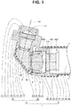
- An image pickup unit for endoscope shown in Fig. 1 is an image pickup unit 1 for a side-view type endoscope.
- the image pickup unit 1 includes an objective lens unit 2 and an image pickup device unit 3.
- the objective lens unit 2 includes a first lens unit 10, a second lens unit 20, and a prism 31.
- Reference sign 4 denotes a first frame fixing portion described later configured to bond and fix lens units included in the objective lens unit 2.
- Reference sign 5 denotes a second frame fixing portion described later configured to bond and fix the objective lens unit and the image pickup device unit.
- the first lens unit 10 includes: a first lens frame 11; a plurality of optical lenses 12, 13, and 14 that are a plurality of optical members; a plurality of diaphragms 15, 16, and 17; and an interval ring 18.
- the first lens frame 11 includes a frame main body 11m and a coupling portion 11j.
- the coupling portion 11j is a convex portion protruding in a predetermined direction by a predetermined distance from a main body proximal end surface 11mr of the frame main body 11m.
- Reference sign 11p denotes prism storage side surfaces forming a prism housing portion 30 described later, and reference sign 11c denotes cover contact surfaces described later.
- a lens frame fixing hole 11h5 that is a through hole and that leads to the prism housing portion 30 is provided on the coupling portion 11j.
- a small diameter portion 21 a of a second lens frame 21 described later is fitted to the lens frame fixing hole 11h5.
- Reference sign 11jr denotes a coupling portion proximal end surface
- reference sign 11jf denotes a coupling portion distal end surface.
- the frame main body 11m has a predetermined pipe shape and includes a first frame hole 11h.
- the first frame hole 11h is a stepped through hole.
- a first hole 11h1, a second hole 11h2, a third hole 11h3, and a fourth hole 11h4 are formed, and a first step surface 11s1, a second step surface 11s2, and a third step surface 11s3 are provided.
- the main body distal end surface 11mf is a plane surface orthogonal to a center axis of the first frame hole 11h, and the first step surface 11s1, the second step surface 11s2, and the third step surface 11s3 are also plane surfaces parallel to the main body distal end surface 11mf.
- Hole diameters of the respective holes are set to predetermined sizes.
- the first hole 11h1 has a largest diameter, and the diameters decrease in order of the second hole 11h2, the third hole 11h3, and the fourth hole 11h4.
- An opening of the first frame hole 11h leading to the prism housing portion 30 is an opening of the fourth hole 11h4.
- the third diaphragm 17 and the interval ring 18 are sequentially housed in the third hole 11h3, and the third diaphragm 17 is arranged on the third step surface 11s3.
- the interval ring 18 is brought into contact with and arranged on the third diaphragm 17, and the interval ring 18 is bonded and fixed by an adhesive.
- the third optical lens 14 is housed in the third hole 11h3.
- the third optical lens 14 is brought into contact with and arranged on the interval ring 18 and bonded and fixed.
- a distal end portion of the third optical lens 14 protrudes by a predetermined distance from the second step surface 11s2 in the state that the lens 14 is brought into contact with and arranged on the interval ring 18.
- the adhesive is applied to an adhesive reservoir formed by distal end portion outer circumference surfaces of the second step surface 11s2 and the third optical lens 14.
- the interval ring 18 may be brought into contact with and arranged on the third diaphragm 17 without bonding and fixing the interval ring 18.
- the third optical lens 14 is brought into contact with and arranged on the interval ring 18 brought into contact with and arranged on the third diaphragm 17.
- the third optical lens 14 is bonded and fixed, and the interval ring 18 is arranged in the third hole 11h3.
- the second diaphragm 16, the second optical lens 13, the first diaphragm 15, and the first optical lens 12 are sequentially housed in the first hole 11h1, and the second diaphragm 16 is arranged on the first step surface 11s1.
- Each of the second optical lens 13, the first diaphragm 15, and the first optical lens 12 is brought into contact with and arranged on the second diaphragm 16 and bonded and fixed.
- the adhesive is applied to a distal end portion outer circumference surface of the first optical lens 12 protruding by a predetermined distance from the main body distal end surface 11mf and applied to the main body distal end surface 11mf.
- the configuration of the first lens unit is not limited to the configuration described above.
- the numbers, the sizes, the shapes, and the like of the optical lenses, the diaphragms, and the interval rings are appropriately set, and a first lens frame corresponding to these is formed.
- predetermined plating is applied in advance to the first optical lens 12.
- the second lens unit 20 includes the second lens frame 21, optical lenses 22 that are a plurality of optical members, a diaphragm 23, and an interval ring 24.
- the second lens frame 21 is a stepped pipe including the small diameter portion 21 a and a large diameter portion 21 b.
- the small diameter portion 21 a is a fitting portion for the coupling portion 11j of the first lens frame 11, and the large diameter portion 21b is a fitting portion for an image pickup device holding frame 45 described later.
- the second lens frame 21 includes a second frame hole 21h.
- the second frame hole 21h is a stepped through hole.
- a first hole 21h1, a second hole 21h2, and a third hole 21h3 are formed, and a first step surface 21s1 and a second step surface 21 s2 are provided.
- the second lens frame proximal end surface 21r is a plane surface orthogonal to a center axis of the second frame hole 21h.
- the first step surface 21s1 is an inclined surface
- a second step surface 21 s2 is a plane surface parallel to the second lens frame proximal end surface 21r.
- Hole diameters of the respective holes are set to predetermined sizes.
- the first hole 21h1 has a largest diameter, and the diameters decrease in order of the second hole 21h2 and the third hole 21h3.
- the diaphragm 23 and the interval ring 24 are sequentially housed in the second hole 21h2, and the diaphragm 23 is arranged on the second step surface 21s2.
- the interval ring 24 is brought into contact with and arranged on the second step surface 21 s2 and bonded and fixed by an adhesive.
- the optical lenses 22 are housed in the second hole 21h2.
- the optical lenses 22 are brought into contact with and arranged on the interval ring 24 and bonded and fixed.
- a proximal end portion of the optical lenses 22 protrudes by a predetermined distance from a proximal end side of the second hole 21h2 in the state that the lenses 22 are brought into contact with and arranged on the interval ring 24.
- the adhesive is applied to an adhesive reservoir formed by distal end portion outer circumference surfaces of the first step surface 21s1 and the optical lenses 22.
- the interval ring 24 may be brought into contact with and arranged on the diaphragm 23 without bonding and fixing the interval ring 24.
- the optical lenses 22 are brought into contact with and arranged on the interval ring 24 brought into contact with and arranged on the diaphragm 23.
- the optical lenses 22 are bonded and fixed, and the interval ring 24 is arranged in the second hole 21h2.
- Reference sign 21f denotes a second lens frame distal end surface
- reference sign 21p denotes a positioning surface.
- the positioning surface 21p is a contact surface coming into contact with the proximal end surface 11jr of the coupling portion 11j.
- the first step surface 21s1 is an inclined surface in the present embodiment, the first step surface 21s1 may be a plane surface parallel to the second lens frame proximal end surface 21r.
- the configuration of the second lens unit is not limited to the configuration described above. The numbers, the sizes, the shapes, and the like of the optical lenses, the diaphragms, and the interval rings are appropriately set, and a second lens frame corresponding to these is formed.
- the coupling portion 11j provided on the first lens frame 11 included in the first lens unit 10 and the small diameter portion 21a provided on the second lens frame 21 included in the second lens unit 20 are bonded and fixed.
- the small diameter portion 21 a of the second lens frame 21 is fitted and arranged in the lens frame fixing hole 11h5 of the coupling portion 11j.
- the positioning surface 21p of the second lens frame 21 is brought into contact with and arranged on the coupling portion proximal end surface 11jr of the coupling portion 11j.
- the first adhesive is cured to fix the small diameter portion 21a of the second lens frame 21 in the lens frame fixing hole 11h5 of the coupling portion 11j.
- the coupling portion 11j provided on the first lens frame 11 and the small diameter portion 21a of the second lens frame 21 indicated by dashed lines are integrated and fixed by the first frame fixing portion 4 formed by curing of the first adhesive.
- the first lens unit 10 and the second lens unit 20 are assembled in a predetermined state.
- the first adhesive is applied in advance to an outer circumference surface of the small diameter portion 21a that is a first fitting surface of the second lens frame 21 before the small diameter portion 21 a is fitted and arranged in the lens frame fixing hole 11h5 that is a first fitting surface of the coupling portion 11j, or the first adhesive is supplied to a gap between the outer circumference surface of the small diameter portion 21a and an inner circumference surface of the lens frame fixing hole 11h5 after the small diameter portion 21a of the second lens frame 21 is fitted and arranged in the lens frame fixing hole 11h5.
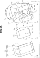
- the prism 31 is formed in a predetermined shape and includes an incident surface 31 a, an emitting surface 31 b, and a reflecting surface 31c.
- Reference sign 30 denotes a housing portion
- reference sign 32 denotes a cover member.
- the cover member 32 covers entire prism surfaces exposed to the outside, such as the reflecting surface 31c of the prism 31 housed in the prism housing portion 30.
- the prism housing portion 30 is provided on a predetermined part of the first lens frame 11, and the prism 31 is housed in the prism housing portion 30.
- the incident surface 31a of the prism 31 to be housed is brought into contact with and arranged on the main body proximal end surface 11mr of the first lens frame 11 included in the first lens unit 10 and is bonded and fixed.
- the emitting surface 31b of the prism 31 to be housed is brought into contact with and arranged on the second lens frame distal end surface 21 f of the second lens frame 21 included in the second lens unit 20 and is bonded and fixed.
- side surfaces 31s of the prism 31 are respectively brought into contact with and arranged on the prism storage side surfaces 11p of the prism housing portion 30 in the housed state.
- the reflecting surface 31c and other surfaces 31e that are surfaces other than the incident surface 31a, the emitting surface 31b, and the side surfaces 31s of the prism 31 are exposed from an opening part of the prism housing portion 30.
- the surface of the prism 31 exposed from the opening part of the prism housing portion 30 is covered by the cover member 32.
- the cover member 32 is formed in a predetermined shape.
- An inner surface 32i of the cover member 32 is divided into a cover region 32ia covering the prism 31 and fixation regions 32ib bonded and fixed in contact with the cover contact surfaces 11c.
- the fixation regions 32ib are provided on both side portions of the cover region 32ia.
- the cover region 32ia covers the reflecting surface 31c and the other surfaces 31e in the state that the fixing portions 32ib are arranged on the cover contact surfaces 11c and bonded and fixed.
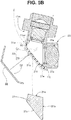
- the objective lens unit 2 covered by the prism 31 bonded and fixed to the first lens frame 11 and the second lens frame 21 and covered by the cover member 32 is formed as indicated by dashed lines in Fig. 5B .
- a light-shielding adhesive 90 is filled in the gap between the inner surface 32i and the surface of the prism 31 to form the objective lens unit 2.
- the objective lens unit 2 is formed without filling the adhesive 90.
- At least one of the cover member 32 and the adhesive 90 is light-shielding.
- the image pickup device unit 3 includes an image pickup device 41, a circuit substrate 42, a centered lens 43 that also serves as a cover member, an optical lens 44, the image pickup device holding frame 45, a diaphragm 46, a shield member 47, and a heat-shrinkable tube 48.
- the image pickup device 41 is a solid-state image pickup device, such as a CCD and a C-MOS, and is mounted on a predetermined position of the circuit substrate 42.
- An image pickup surface provided on a front surface of the image pickup device 41 receives light passing through the objective lens unit 2.
- the image pickup surface is covered by the transparent centered lens 43 and protected.
- One surface of the centered lens 43 is arranged on the front surface of the image pickup device 41 and integrally bonded and fixed to the image pickup device 41 by a transparent adhesive.
- One surface of the optical lens 44 is arranged on a front surface of the centered lens 43 and is integrally bonded and fixed to the optical lens 44 by the transparent adhesive.
- the image pickup device holding frame 45 is cylindrical and is a fitting portion for the objective lens unit 2.
- the image pickup device holding frame 45 includes a space portion 45S and a lens arrangement hole 45h.
- the lens arrangement hole 45h is a through hole connecting the space portion 45S and the outside, and the optical lens 44 is integrated and fixed to the lens arrangement hole 45h by, for example, an adhesive.
- the space portion 45S is a fitting hole for fitting the large diameter portion 21b of the second lens frame 21 of the second lens unit 20.
- the diaphragm 46 is located in the fitting hole.
- the diaphragm 46 is arranged on a bottom surface 45b of the space portion 45S and bonded and fixed.
- An inner surface of a distal end side end portion of the shield member 47 is arranged on an outer surface of the image pickup device holding frame 45, and the inner surface is integrated and fixed to the holding frame 45 by, for example, a conductive adhesive.
- An outer circumference of the shield member 47 is covered by the heat-shrinkable tube 48, and an insulating sealing resin is filled in an internal space 46S of the shield member 47.
- connection terminals (not shown) provided on predetermined positions of the circuit substrate 42, signal lines connected to the connection terminals, and the like are not illustrated.
- the second lens frame 21 of the second lens unit 20 included in the objective lens unit 2 and the image pickup device holding frame 45 included in the image pickup device unit 3 are bonded and fixed.
- the large diameter portion 21b of the second lens frame 21 is fitted and arranged in the space portion 45S of the image pickup device holding frame 45, and the focus is adjusted.
- a second adhesive is cured in a state that the focus adjustment is completed, and the large diameter portion 21b of the second lens frame 21 is fixed in the space portion 45S of the image pickup device holding frame 45.
- the second lens frame 21 of the objective lens unit 2 and the image pickup device holding frame 45 of the image pickup device unit 3 are integrated and fixed by the second frame fixing portion 5 formed by curing of the second adhesive, and the image pickup unit 1 is formed in which the objective lens unit 2 and the image pickup device unit 3 are integrated.
- a fitting area of a second fitting surface formed by an outer circumference surface of the second lens frame 21 included in the second frame fixing portion 5 and an inner circumference surface of the image pickup device holding frame 45 is set greater than a fitting area of a first fitting surface formed by the inner circumference surface of the lens frame fixing hole 11h5 included in the first frame fixing portion 4 and an outer circumference surface of the second lens frame 21.
- the second adhesive is an adhesive with a glass transition temperature lower than the first adhesive.
- the first adhesive is an epoxy resin material
- the second adhesive is a silicone resin material.
- the first adhesive and the second adhesive have adjusted glass transition temperatures.
- the second adhesive is applied in advance to an outer circumference surface of the large diameter portion 21b before the large diameter portion 21b that is a second fitting surface is fitted and arranged in the space portion 45S of the image pickup device holding frame 45 that is a second fitting surface, or the second adhesive is supplied to a gap between the outer circumference surface of the large diameter portion 21b and the inner circumference surface of the space portion 45S after the large diameter portion 21b is fitted and arranged in the space portion 45S.
- An image pickup unit that has failed the inspection in the present embodiment (described as an image pickup unit N) is not discarded, and the image pickup unit is disassembled into the objective lens unit 2 and the image pickup device unit 3.
- a worker performs work for disassembling the image pickup unit N into the objective lens unit 2 and the image pickup device unit 3 while heating the image pickup device holding frame 45 and the second lens frame 21 of the image pickup unit N by a heater or a burner.
- an apparatus such as a spot heater, is used for the heating.
- a furnace such as a drying furnace, is used to heat the resin materials up to predetermined temperatures. In this way, stable disassemble work can be performed.
- the temperatures of the image pickup device holding frame 45 and the second lens frame 21 rise due to the heating the temperatures of the second frame fixing portion 5 and the first frame fixing portion 4 also rise.
- the first frame fixing portion 4 and the second frame fixing portion 5 are formed by the first adhesive and the second adhesive with different glass transition temperatures.
- the glass transition temperature of the second adhesive is set lower than the glass transition temperature of the first adhesive.
- the second adhesive of the second frame fixing portion 5 starts to soften at a predetermined temperature lower than the first adhesive of the first frame fixing portion 4.
- the second frame fixing portion 5 with a large fitting area in the image pickup unit N is broken up, and the image pickup unit N is disassembled into the objective lens unit 2 and the image pickup device unit 3.
- the objective lens unit 2 and the image pickup device unit 3 of the image pickup unit N can be reused through predetermined work.
- the disassemble work can be performed under the normal temperature environment for performing the disassemble work without the heating, because the glass transition temperature of the silicone adhesive is generally below zero.
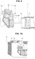
- the image pickup unit 1 that has passed the inspection is attached to a distal end rigid member 81 as shown in Fig. 7A , and a side-view type endoscope 80 is formed as shown in Fig. 7B .
- Reference sign 82 of Fig. 7A denotes an image pickup unit opening, and the first lens frame 11 of the image pickup unit 1 is attached to the image pickup unit opening 82 provided on the distal end rigid member 81.
- Reference sign 83 denotes an illumination lens which is fixed and installed on an illumination opening 84.
- Reference sign 85 of Fig. 7B denotes a distal end cover, and the distal end rigid member 81 is integrally fixed and installed in the distal end cover 85.
- Reference sign 86 denotes a light guide bundle, and a distal end surface of the light guide bundle 86 is faced by the illumination lens 83.
- Reference sign 87 denotes a bundle holding member, and the bundle holding member 87 is a resin member configured to hold the light guide bundle 86. Note that the holding member 87 is not limited to the resin member, and the holding member 87 may be a metal member.
- lens breakage such as cracking and fracture
- lens fogging may occur in the first optical lens 12 during the use, or lens fogging may occur. This may obstruct the observation.
- the side-view type endoscope 80 with the lens breakage or lens fogging is sent for repair.
- the image pickup unit 1 is used for the side-view type endoscope 80. Therefore, the image pickup unit 1 can be disassembled into the objective lens unit 2 and the image pickup device unit 3 as described above.
- the objective lens unit 2 can be discarded, and on the other hand, the image pickup device unit 3 can be reused.
- the glass transition temperature of the second adhesive forming the second frame fixing portion 5 configured to bond and fix the objective lens unit 2 and the image pickup device unit 3 is set lower than the glass transition temperature of the first adhesive forming the first connection portion 4 configured to bond and fix the lens units 10 and 20 included in the objective lens unit 2.
- the second frame fixing portion 5 with a large fitting area can be broken up without breaking up the first frame fixing portion 4 with a small fitting area, and the image pickup unit 1 can be easily disassembled into the objective lens unit 2 and the image pickup device unit 3.
- a circumferential groove 21g is provided on the large diameter portion 21b of the second lens frame 21 fitted and arranged in the space portion 45S of the image pickup device holding frame 45.
- the circumferential groove 21g is provided such that a surface area of the large diameter portion 21b is smaller than an inner surface area of the lens frame fixing hole 11h5 provided on the coupling portion 11j.
- a bonding area of the second frame fixing portion 5 formed by the second adhesive is smaller than a bonding area of the first frame fixing portion 4 formed by the first adhesive.
- the worker when the worker heats the image pickup device holding frame 45 and the second lens frame 21 to disassemble the image pickup unit N, the worker can break up the second frame fixing portion 5 of the image pickup unit N by reducing the heating time upon the start of the softening of the second adhesive forming the second frame fixing portion 5, and the worker can more smoothly disassemble the image pickup unit N into the objective lens unit 2 and the image pickup device unit 3.
- the bonding area of the second frame fixing portion 5 formed by the second adhesive with a glass transition temperature lower than the first adhesive is set smaller than the bonding area of the first frame fixing portion 4 formed by the first adhesive. Therefore, a predetermined amount of force can be applied to perform the disassemble work without heating the image pickup device holding frame 45 and the second lens frame 21 of the image pickup unit N, and the second frame fixing portion 5 can be broken up to easily disassemble the image pickup unit 1 into the objective lens unit 2 and the image pickup device unit 3.
- a bonding surface portion and a non-bonding surface portion may be provided on a fitting surface 21bf of the large diameter portion 21b of the second lens frame 21 fitted and arranged in the space portion 45S of the image pickup device holding frame 45.
- a circumferential direction concave portion 21c is provided, and the fitting surface 21bf of the large diameter portion 21b is divided into the circumferential direction concave portion 21c serving as a bonding surface portion, a first fitting surface portion 21t1, and a second fitting surface portion 21t2.
- the circumferential direction concave portion 21c is an adhesive reservoir and is provided between the first fitting surface portion 21t1 and the second fitting surface portion 21t2.
- the fitting surface 21bf of the large diameter portion 21b is fitted and arranged in the space portion 45S of the image pickup device holding frame 45.
- the first fitting surface portion 21t1 of the large diameter portion 21b is brought into contact with and arranged in the space portion 45 S of the image pickup device holding frame 45 through predetermined fitting.
- a width of the circumferential direction concave portion 21c is set such that the bonding area of the second frame fixing portion 5 is smaller than the bonding area of the first frame fixing portion 4.
- an outer circumference surface of the first fitting surface portion 21t1 that is the non-bonding surface portion of the large diameter portion 21b is arranged on the inner circumference surface of the space portion 45S of the image pickup device holding frame 45 without the adhesive, and highly accurate assembly can be realized.
- an inclined surface 21s extending toward the second fitting surface portion 21t2 side can be provided to more effectively prevent the adhesive applied in the circumferential direction concave portion 21c from passing through the first fitting surface portion 21t1 and entering the proximal end surface side of the second lens frame 21 to become waste in the fitting arrangement work.
- a third fixing portion 6 is provided in addition to the second frame fixing portion 5 as shown in Fig. 10 .
- the third fixing portion 6 is formed by applying the second adhesive in close contact with the first lens frame 11, the second lens frame 21, and the image pickup device holding frame 45.
- the third fixing portion 6 is provided in addition to the second frame fixing portion 5, and this can realize the image pickup unit 1 in which fixing strength of the objective lens unit 2 and the image pickup device unit 3 is improved.
- the third fixing portion 6 is broken up first, and then the image pickup unit 1 is disassembled into the objective lens unit 2 and the image pickup device unit 3 as described above.
- the image pickup device unit 3 is reused.
- a notch portion 11mc is provided on a predetermined part of the flange portion 11mf of the frame main body 11m included in the first lens frame 11.
- an outside diameter of the holding frame 45 is extended with respect to an axis center of the frame 45 to enlarge the diameter.
- a thickness of the annular image pickup device holding frame 45 can be increased while maintaining an inside diameter, and the area of the distal end surface of the image pickup device holding frame 45 can be increased.
- the increased distal end surface of the image pickup device holding frame 45 is set as a bonding surface of the coupling portion 11j and the coupling portion proximal end surface 11jr of the first lens frame 11.
- the second frame fixing portion 5 is provided to bond and fix the increased distal end surface of the image pickup device holding frame 45 to the coupling portion 11j of the first lens frame 11, and this can realize the image pickup unit 1 in which the fixation strength of the objective lens unit 2 and the image pickup device unit 3 is improved.
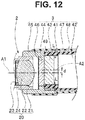
- a space of the image pickup device 41 in a side surface direction becomes non-uniform. Residual stress at cure shrinkage of the sealing resin filled in the non-uniform space is applied in one direction, and the image pickup device 41 may be broken up.
- a device frame arrangement space 45S1 is displaced from a position of a solid line to a position of an alternate long and two short dashes line such that an inner circumference surface 45f of the device frame arrangement space 45S1 of the image pickup device holding frame 45 and a side surface of the image pickup device 41 become uniform.
- the large diameter portion 21b is fitted and arranged in the space portion 45S of the image pickup device holding frame 45 in the embodiment described above.
- the image pickup device holding frame 45 may be fitted and arranged in an inner hole of the large diameter portion 21b.
- the image pickup unit 1 is for the side-view type endoscope in the embodiment described above.
- the image pickup unit is not limited to the image pickup unit for the side-view type endoscope, and the image pickup unit may be an image pickup unit for a front-view type endoscope as shown in Fig. 13 .
- the image pickup unit 1A for front-view type endoscope includes an objective lens unit 2A and the image pickup device unit 3.
- the objective lens unit 2A includes a first lens unit 100, a second lens unit 200, a moving lens unit 300, and a coupling frame 311.
- Reference sign 7 denotes first frame fixing portions which are fixed by metal junction, such as soldering and brazing.
- reference sign 8 denotes a second frame fixing portion which is bonded and fixed by an adhesive.
- the first lens unit 100 includes a first lens frame 101, a plurality of optical lenses 102 that are a plurality of optical members, and a diaphragm 103. Note that the number of diaphragms is not limited to one, and more diaphragms may be included. An interval ring may also be provided.
- the first lens frame 101 has a predetermined pipe shape and includes a first frame hole 104.
- the first frame hole 104 is a stepped through hole in a predetermined shape, and an optical member is appropriately fixed and installed.
- the second lens unit 200 includes a second lens frame 201, a plurality of optical lenses 202 that are a plurality of optical members, and a plurality of diaphragms 103. Note that an interval ring may also be provided.
- the second lens frame 201 has a predetermined pipe shape and includes a second frame hole 204.
- the second frame hole 204 is a stepped through hole in a predetermined shape, and an optical member is appropriately fixed and installed.
- the moving lens unit 300 includes a moving lens frame 301, a plurality of optical lenses 302, a diaphragm 303, and a moving lens frame movement mechanism 304.
- the moving lens frame movement mechanism 304 is a publicly-known technique and will not be described.
- the number of diaphragms is not limited to one, and more diaphragms may be included.
- An interval ring may also be provided.
- the moving lens frame 301 includes a frame main body 305 and a movement rod 306.
- the frame main body 305 is cylindrical and includes a concave portion 307 and a third frame hole 308.
- the first lens frame 101 is loosely fitted and arranged in the concave portion 307.
- the third frame hole 308 is an axial direction through hole connecting the concave portion 307 and the outside, and the optical lenses 302 are fixed and installed.
- the diaphragm 303 is fixed and installed on a bottom surface of the concave portion 307, for example.
- a distal end portion of the moving lens frame movement mechanism 304 is integrated and fixed to the movement rod 306.
- the coupling frame 311 has a predetermined pipe shape and includes a fourth frame hole 312 that is an axial direction through hole and a long hole 313 connecting the fourth frame hole 312 and the outside.
- the long hole 313 is provided on a predetermined position of a side portion of the coupling frame 311, and the movement rod 306 is arranged in a manner that the movement rod 306 can freely move back and forth.
- the first lens frame 101 is fitted and arranged on a distal end opening side of the fourth frame hole 312, and the first frame fixing portions 7 based on metal junction, such as soldering, are provided for integrated fixation.
- the second lens frame 201 is fitted and arranged on a proximal end opening side of the fourth frame hole 312, and the first frame fixing portions 7 are provided for integrated fixation.
- the frame main body 305 of the moving lens frame 301 is arranged in the fourth frame hole 312 in a manner that the frame main body 305 can freely move back and forth.
- the objective lens unit 2A is formed in which the first lens unit 100, the second lens unit 200, and the coupling frame 311 are integrated and fixed, and the moving lens unit 300 is arranged in the coupling frame 311 in a manner that the moving lens unit 300 can freely move back and forth.
- the second lens frame 201 of the second lens unit 200 included in the objective lens unit 2A and the image pickup device holding frame 45 included in the image pickup device unit 3 are bonded and fixed.
- a small diameter portion 201 a of the second lens frame 201 is fitted and arranged in the space portion 45S of the image pickup device holding frame 45, and the focus is adjusted.
- the adhesive is cured in a state that the focus adjustment is completed, and the small diameter portion 201 a of the second lens frame 201 is fixed in the space portion 45S of the image pickup device holding frame 45.
- the second lens frame 201 of the objective lens unit 2A and the image pickup device holding frame 45 of the image pickup device unit 3 are integrated and fixed by the second frame fixing portion 8 formed by curing of the adhesive as illustrated in the drawing, and the image pickup unit 1A is formed in which the objective lens unit 2A and the image pickup device unit 3 are integrated.
- the adhesive is a silicone resin material or an epoxy resin material with the melting point lower than the soldering.
- the adhesive is applied in advance to an outer circumference surface of the small diameter portion 201 a before the small diameter portion 201a is fitted and arranged in the space portion 45S, or the adhesive is supplied to a gap between the outer circumference surface of the small diameter portion 201a and an inner circumference surface of the space portion 45 S after the small diameter portion 201a is fitted and arranged in the space portion 45S.
- An image pickup unit that has failed the inspection in the present embodiment (described as an image pickup unit NA) is not discarded, and the image pickup unit NA is disassembled into the objective lens unit 2A and the image pickup device unit 3.
- the worker performs work of disassembling the image pickup unit NA into the objective lens unit 2A and the image pickup device unit 3 while heating the image pickup device holding frame 45 and the second lens frame 201 of the image pickup unit NA by a heater or a burner.
- the temperatures of the image pickup device holding frame 45 and the second lens frame 21 rise due to the heating the temperatures of the metal-junction first frame fixing portions 7 and the bonded and fixed second frame fixing portion 8 also rise.
- the first frame fixing portions 7 and the second frame fixing portion 8 have different melting points. Therefore, the adhesive of the second frame fixing portion 8 starts to soften at a predetermined temperature lower than the soldering of the first frame fixing portions 7.
- the second frame fixing portion 8 of the image pickup unit NA is broken up, and the image pickup unit NA is disassembled into the objective lens unit 2A and the image pickup device unit 3.
- the objective lens unit 2A and the image pickup device unit 3 of the image pickup unit NA can be reused through predetermined work.
- the image pickup unit 1A that has passed the inspection is attached to a distal end rigid member not shown, and a front-view type endoscope (not shown) is formed.
- the objective lens unit 2A and the image pickup device unit 3 are fixed by the second frame fixing portion 8 based on bonding and fixation, and the plurality of lens units 100 and 200 and the coupling frame 311 included in the objective lens unit 2A are fixed by the first frame fixing portions 7 based on metal junction.
- the first frame fixing portions 7 are not melted, and the second frame fixing portion 8 based on the adhesive can be broken up to easily disassemble the image pickup unit 1A into the objective lens unit 2A and the image pickup device unit 3.
- the first frame fixing portions 7 of the image pickup unit 1A for the front-view type endoscope are based on the metal junction.
- the first frame fixing portions 7 may be the first frame fixing portion 4 formed by the first adhesive
- the second frame fixing portion 8 may be the second frame fixing portion 5 formed by the second adhesive as in the image pickup unit 1.
- the image pickup unit 1A is not limited to an image pickup unit including the moving lens frame unit 300, and a configuration that does not require the moving lens frame unit 300 is also possible.
- the first frame fixing portion 4 based on the first adhesive in the image pickup unit 1 may be the first frame fixing portions 7 based on the metal junction.
- the present invention can realize an image pickup unit for endoscope that can disassemble and reuse a lens unit and an image pickup device unit after breaking up a predetermined frame fixing portion without breaking the lens unit and the image pickup device unit, while reducing the diameter of an insertion portion and shortening a rigid portion.
Landscapes
- Health & Medical Sciences (AREA)
- Life Sciences & Earth Sciences (AREA)
- Physics & Mathematics (AREA)
- Surgery (AREA)
- Optics & Photonics (AREA)
- Engineering & Computer Science (AREA)
- Biomedical Technology (AREA)
- Veterinary Medicine (AREA)
- Biophysics (AREA)
- Pathology (AREA)
- Radiology & Medical Imaging (AREA)
- Nuclear Medicine, Radiotherapy & Molecular Imaging (AREA)
- Public Health (AREA)
- Heart & Thoracic Surgery (AREA)
- Medical Informatics (AREA)
- Molecular Biology (AREA)
- Animal Behavior & Ethology (AREA)
- General Health & Medical Sciences (AREA)
- General Physics & Mathematics (AREA)
- Astronomy & Astrophysics (AREA)
- Multimedia (AREA)
- Signal Processing (AREA)
- Endoscopes (AREA)
- Instruments For Viewing The Inside Of Hollow Bodies (AREA)
- Lens Barrels (AREA)
Abstract
Description
- The present invention relates to an image pickup unit for endoscope including a solid-state image pickup device built in an insertion portion of an endoscope.
- In recent years, an endoscope has been used in a medical field and an industrial field. The endoscope can perform observation, treatment, and the like by inserting an elongated insertion portion into a tube with a small diameter. Reduction in the diameter of the insertion portion and shortening of a rigid portion are demanded in the endoscope in order to improve an insertion property.
- In a so-called electronic endoscope including an image pickup unit for endoscope (hereinafter, abbreviated as an image pickup unit) built in a distal end portion of an insertion portion, the number of pixels of a solid-state image pickup device is increased, for example, in order to improve an observation performance.
- In the image pickup unit, an objective lens unit and an image pickup device unit including the solid-state image pickup device are integrated. The image pickup device unit is an expensive unit among the units included in the endoscope.
- The objective lens unit includes optical lenses that are a plurality of optical members, an interval ring, a diaphragm, and the like, which are fixed and installed in a lens frame.
- On the other hand, the image pickup device unit mainly includes: a solid-state image pickup device (hereinafter, abbreviated as an image pickup device), such as a CCD and a C-MOS; a circuit substrate on which the image pickup device and various electronic components are mounted; and a plurality of signal lines connected to the circuit substrate.
- The objective lens unit and the image pickup device unit are formed as an image pickup unit in which a lens frame forming the objective lens unit and a holding frame forming the image pickup device unit are integrated and fixed by bonding or joining.
- Japanese Patent Application Laid-Open Publication No.
2009-273642 - Therefore, the first lens holding frame attachment portion is installed on a first lens unit, and the second lens holding frame attachment portion is installed on a second lens unit. As a result, the optical axes can be easily aligned, and the assembly work efficiency becomes excellent. Note that a holder tube of an image pickup device holder is fitted and fixed onto the second lens unit.
- Japanese Patent Application Laid-Open Publication No.
2006-015076 - However, in the image pickup unit for endoscope of Japanese Patent Application Laid-Open Publication No.
2009-273642 - On the other hand, although the image pickup unit can be repaired and exchanged in Japanese Patent Application Laid-Open Publication No.
2006-015076 - Note that it is assumed that a first frame member and a second frame member are respectively provided on a distal end side and a proximal end side across one frame member, and frame members are integrated and fixed by providing frame fixing portions based on joining or bonding. In this case, if a fitting area of a first frame fixing portion provided on the distal end side of the frame member and a fitting area of a second frame fixing portion provided on the proximal end side of the frame member are different, and a same adhesive is applied to respective fitting surfaces to provide the first frame fixing portion and the second frame fixing portion, the frame fixing portion with a small fitting area is broken up by a smaller load than the frame fixing portion with a large fitting area when a load is applied to break up the frame fixing portions.
- The present invention has been made in view of the above circumstances, and an object of the present invention is to provide an image pickup unit for endoscope that can disassemble and reuse a lens unit and an image pickup device unit after breaking up a predetermined frame fixing portion without breaking the lens unit and the image pickup device unit, while reducing the diameter of an insertion portion and shortening a rigid portion.
- An aspect of the present invention provides an image pickup unit for endoscope including: an objective lens unit including a plurality of optical members configured to guide light from an object and a plurality of lens frames configured to hold the plurality of optical members; an image pickup device unit including a solid-state image pickup device configured to receive the light and a holding frame configured to hold at least one optical lens; a first frame fixing portion configured to apply a first adhesive to respective first fitting surfaces of the lens frames provided on the objective lens unit to bond and fix the first fitting surfaces; and a second frame fixing portion configured to apply a second adhesive with a glass transition temperature lower than the first adhesive to second fitting surfaces that are fitting surfaces of the lens frames of the objective lens unit and the holding frame of the image pickup device unit and that have fitting areas greater than fitting areas of the first fitting surfaces to bond and fix the second fitting surfaces.
-
-
Fig. 1 is a diagram describing an example of configuration of an image pickup unit for endoscope; -
Fig. 2 is a diagram describing a first lens unit included in an objective lens unit; -
Fig. 3 is a diagram describing a second lens unit included in the objective lens unit; -
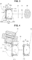
Fig. 4 is a diagram describing assembly of the first lens unit and the second lens unit; -
Fig. 5A is a diagram describing a relationship between a first lens frame and a prism; -
Fig. 5B is a diagram describing the objective lens unit formed by assembling a prism unit to the integrated and assembled first lens unit and second lens unit; -
Fig. 6 is a diagram describing assembly of the objective lens unit and an image pickup device unit; -
Fig. 7A is a diagram showing the image pickup device unit arranged on a distal end rigid member; -
Fig. 7B is a diagram showing a side-view type endoscope including the image pickup device unit; -
Fig. 8 is a diagram describing another configuration of a second lens frame included in the second lens unit; -
Fig. 9A is a diagram showing another configuration of the second lens frame included in the second lens unit and a state of assembly to an image pickup device holding frame; -
Fig. 9B is a diagram showing another configuration of the second lens frame included in the second lens unit and a state of assembly to the image pickup device holding frame; -
Fig. 9C is a diagram showing another configuration of the second lens frame included in the second lens unit and a state of assembly to the image pickup device holding frame; -
Fig. 10 is a diagram describing an example of configuration for improving a fixation strength of the objective lens unit and the image pickup device unit; -
Fig. 11 is a diagram describing another example of configuration for improving the fixation strength of the objective lens unit and the image pickup device unit; -
Fig. 12 is a diagram describing a configuration of protecting an image pickup device from residual stress in a configuration in which an optical axis and a center line of the image pickup device are displaced; and -
Fig. 13 is a diagram describing another example of configuration of the image pickup unit for endoscope. - Hereinafter, an embodiment of the present invention will be described with reference to the drawings.
- Note that scaling of each constituent element may vary in each drawing used in the following description in order to illustrate each constituent element in a size that allows recognizing the constituent element on the drawing. That is, the present invention is not limited only to quantities of the constituent elements, shapes of the constituent elements, ratios of the sizes of the constituent elements, and relative positional relationships between respective constituent elements described in the drawings.
- An image pickup unit for endoscope shown in
Fig. 1 is animage pickup unit 1 for a side-view type endoscope. - The
image pickup unit 1 includes anobjective lens unit 2 and an imagepickup device unit 3. Theobjective lens unit 2 includes afirst lens unit 10, asecond lens unit 20, and aprism 31. - Reference sign 4 denotes a first frame fixing portion described later configured to bond and fix lens units included in the
objective lens unit 2.Reference sign 5 denotes a second frame fixing portion described later configured to bond and fix the objective lens unit and the image pickup device unit. - The
first lens unit 10 includes: afirst lens frame 11; a plurality ofoptical lenses diaphragms interval ring 18. - As shown in
Fig. 2 , thefirst lens frame 11 includes a framemain body 11m and acoupling portion 11j. Thecoupling portion 11j is a convex portion protruding in a predetermined direction by a predetermined distance from a main body proximal end surface 11mr of the framemain body 11m.Reference sign 11p denotes prism storage side surfaces forming aprism housing portion 30 described later, andreference sign 11c denotes cover contact surfaces described later. - A lens frame fixing hole 11h5 that is a through hole and that leads to the
prism housing portion 30 is provided on thecoupling portion 11j. Asmall diameter portion 21 a of asecond lens frame 21 described later is fitted to the lens frame fixing hole 11h5. Reference sign 11jr denotes a coupling portion proximal end surface, and reference sign 11jf denotes a coupling portion distal end surface. - The frame
main body 11m has a predetermined pipe shape and includes afirst frame hole 11h. Thefirst frame hole 11h is a stepped through hole. In order from a main body distal end surface 11mf side, a first hole 11h1, a second hole 11h2, a third hole 11h3, and a fourth hole 11h4 are formed, and a first step surface 11s1, a second step surface 11s2, and a third step surface 11s3 are provided. - Note that the main body distal end surface 11mf is a plane surface orthogonal to a center axis of the
first frame hole 11h, and the first step surface 11s1, the second step surface 11s2, and the third step surface 11s3 are also plane surfaces parallel to the main body distal end surface 11mf. Hole diameters of the respective holes are set to predetermined sizes. The first hole 11h1 has a largest diameter, and the diameters decrease in order of the second hole 11h2, the third hole 11h3, and the fourth hole 11h4. An opening of thefirst frame hole 11h leading to theprism housing portion 30 is an opening of the fourth hole 11h4. - In the present embodiment, the
third diaphragm 17 and theinterval ring 18 are sequentially housed in the third hole 11h3, and thethird diaphragm 17 is arranged on the third step surface 11s3. Theinterval ring 18 is brought into contact with and arranged on thethird diaphragm 17, and theinterval ring 18 is bonded and fixed by an adhesive. - The third
optical lens 14 is housed in the third hole 11h3. The thirdoptical lens 14 is brought into contact with and arranged on theinterval ring 18 and bonded and fixed. A distal end portion of the thirdoptical lens 14 protrudes by a predetermined distance from the second step surface 11s2 in the state that thelens 14 is brought into contact with and arranged on theinterval ring 18. The adhesive is applied to an adhesive reservoir formed by distal end portion outer circumference surfaces of the second step surface 11s2 and the thirdoptical lens 14. - Note that the
interval ring 18 may be brought into contact with and arranged on thethird diaphragm 17 without bonding and fixing theinterval ring 18. In this case, the thirdoptical lens 14 is brought into contact with and arranged on theinterval ring 18 brought into contact with and arranged on thethird diaphragm 17. The thirdoptical lens 14 is bonded and fixed, and theinterval ring 18 is arranged in the third hole 11h3. - The
second diaphragm 16, the secondoptical lens 13, thefirst diaphragm 15, and the firstoptical lens 12 are sequentially housed in the first hole 11h1, and thesecond diaphragm 16 is arranged on the first step surface 11s1. Each of the secondoptical lens 13, thefirst diaphragm 15, and the firstoptical lens 12 is brought into contact with and arranged on thesecond diaphragm 16 and bonded and fixed. - The adhesive is applied to a distal end portion outer circumference surface of the first
optical lens 12 protruding by a predetermined distance from the main body distal end surface 11mf and applied to the main body distal end surface 11mf. - Note that the configuration of the first lens unit is not limited to the configuration described above. The numbers, the sizes, the shapes, and the like of the optical lenses, the diaphragms, and the interval rings are appropriately set, and a first lens frame corresponding to these is formed. When the first
optical lens 12 is fixed by brazing, predetermined plating is applied in advance to the firstoptical lens 12. - As shown in
Fig. 1 , thesecond lens unit 20 includes thesecond lens frame 21,optical lenses 22 that are a plurality of optical members, adiaphragm 23, and aninterval ring 24. - As shown in
Fig. 3 , thesecond lens frame 21 is a stepped pipe including thesmall diameter portion 21 a and alarge diameter portion 21 b. Thesmall diameter portion 21 a is a fitting portion for thecoupling portion 11j of thefirst lens frame 11, and thelarge diameter portion 21b is a fitting portion for an image pickupdevice holding frame 45 described later. - The
second lens frame 21 includes asecond frame hole 21h. Thesecond frame hole 21h is a stepped through hole. In order from a second lens frameproximal end surface 21r side, a first hole 21h1, a second hole 21h2, and a third hole 21h3 are formed, and a first step surface 21s1 and asecond step surface 21 s2 are provided. - Note that the second lens frame
proximal end surface 21r is a plane surface orthogonal to a center axis of thesecond frame hole 21h. The first step surface 21s1 is an inclined surface, and asecond step surface 21 s2 is a plane surface parallel to the second lens frameproximal end surface 21r. Hole diameters of the respective holes are set to predetermined sizes. The first hole 21h1 has a largest diameter, and the diameters decrease in order of the second hole 21h2 and the third hole 21h3. - In the present embodiment, the
diaphragm 23 and theinterval ring 24 are sequentially housed in the second hole 21h2, and thediaphragm 23 is arranged on the second step surface 21s2. Theinterval ring 24 is brought into contact with and arranged on thesecond step surface 21 s2 and bonded and fixed by an adhesive. - The
optical lenses 22 are housed in the second hole 21h2. Theoptical lenses 22 are brought into contact with and arranged on theinterval ring 24 and bonded and fixed. A proximal end portion of theoptical lenses 22 protrudes by a predetermined distance from a proximal end side of the second hole 21h2 in the state that thelenses 22 are brought into contact with and arranged on theinterval ring 24. The adhesive is applied to an adhesive reservoir formed by distal end portion outer circumference surfaces of the first step surface 21s1 and theoptical lenses 22. - Note that the
interval ring 24 may be brought into contact with and arranged on thediaphragm 23 without bonding and fixing theinterval ring 24. In this case, theoptical lenses 22 are brought into contact with and arranged on theinterval ring 24 brought into contact with and arranged on thediaphragm 23. Theoptical lenses 22 are bonded and fixed, and theinterval ring 24 is arranged in the second hole 21h2. -
Reference sign 21f denotes a second lens frame distal end surface, andreference sign 21p denotes a positioning surface. Thepositioning surface 21p is a contact surface coming into contact with the proximal end surface 11jr of thecoupling portion 11j. Although the first step surface 21s1 is an inclined surface in the present embodiment, the first step surface 21s1 may be a plane surface parallel to the second lens frameproximal end surface 21r. The configuration of the second lens unit is not limited to the configuration described above. The numbers, the sizes, the shapes, and the like of the optical lenses, the diaphragms, and the interval rings are appropriately set, and a second lens frame corresponding to these is formed. - Assembly of the
first lens unit 10 and thesecond lens unit 20 will be described with reference toFig. 4 . - To integrate and assemble the
first lens unit 10 and thesecond lens unit 20 shown inFig. 4 , thecoupling portion 11j provided on thefirst lens frame 11 included in thefirst lens unit 10 and thesmall diameter portion 21a provided on thesecond lens frame 21 included in thesecond lens unit 20 are bonded and fixed. - More specifically, the
small diameter portion 21 a of thesecond lens frame 21 is fitted and arranged in the lens frame fixing hole 11h5 of thecoupling portion 11j. In this case, thepositioning surface 21p of thesecond lens frame 21 is brought into contact with and arranged on the coupling portion proximal end surface 11jr of thecoupling portion 11j. In this contact state, the first adhesive is cured to fix thesmall diameter portion 21a of thesecond lens frame 21 in the lens frame fixing hole 11h5 of thecoupling portion 11j. - As a result, the
coupling portion 11j provided on thefirst lens frame 11 and thesmall diameter portion 21a of thesecond lens frame 21 indicated by dashed lines are integrated and fixed by the first frame fixing portion 4 formed by curing of the first adhesive. Thefirst lens unit 10 and thesecond lens unit 20 are assembled in a predetermined state. - Note that the first adhesive is applied in advance to an outer circumference surface of the
small diameter portion 21a that is a first fitting surface of thesecond lens frame 21 before thesmall diameter portion 21 a is fitted and arranged in the lens frame fixing hole 11h5 that is a first fitting surface of thecoupling portion 11j, or the first adhesive is supplied to a gap between the outer circumference surface of thesmall diameter portion 21a and an inner circumference surface of the lens frame fixing hole 11h5 after thesmall diameter portion 21a of thesecond lens frame 21 is fitted and arranged in the lens frame fixing hole 11h5. - As shown in
Figs. 5A and5B , theprism 31 is formed in a predetermined shape and includes anincident surface 31 a, an emittingsurface 31 b, and a reflectingsurface 31c.Reference sign 30 denotes a housing portion, andreference sign 32 denotes a cover member. Thecover member 32 covers entire prism surfaces exposed to the outside, such as the reflectingsurface 31c of theprism 31 housed in theprism housing portion 30. - The
prism housing portion 30 is provided on a predetermined part of thefirst lens frame 11, and theprism 31 is housed in theprism housing portion 30. Theincident surface 31a of theprism 31 to be housed is brought into contact with and arranged on the main body proximal end surface 11mr of thefirst lens frame 11 included in thefirst lens unit 10 and is bonded and fixed. The emittingsurface 31b of theprism 31 to be housed is brought into contact with and arranged on the second lens framedistal end surface 21 f of thesecond lens frame 21 included in thesecond lens unit 20 and is bonded and fixed. - Note that side surfaces 31s of the
prism 31 are respectively brought into contact with and arranged on the prism storage side surfaces 11p of theprism housing portion 30 in the housed state. - The reflecting
surface 31c andother surfaces 31e that are surfaces other than theincident surface 31a, the emittingsurface 31b, and the side surfaces 31s of theprism 31 are exposed from an opening part of theprism housing portion 30. The surface of theprism 31 exposed from the opening part of theprism housing portion 30 is covered by thecover member 32. - The
cover member 32 is formed in a predetermined shape. Aninner surface 32i of thecover member 32 is divided into a cover region 32ia covering theprism 31 and fixation regions 32ib bonded and fixed in contact with thecover contact surfaces 11c. - The fixation regions 32ib are provided on both side portions of the cover region 32ia. The cover region 32ia covers the reflecting
surface 31c and theother surfaces 31e in the state that the fixing portions 32ib are arranged on the cover contact surfaces 11c and bonded and fixed. - As a result, the
objective lens unit 2 covered by theprism 31 bonded and fixed to thefirst lens frame 11 and thesecond lens frame 21 and covered by thecover member 32 is formed as indicated by dashed lines inFig. 5B . - Note that when the
inner surface 32i of thecover member 32 is a reflecting surface, a light-shieldingadhesive 90 is filled in the gap between theinner surface 32i and the surface of theprism 31 to form theobjective lens unit 2. On the other hand, when thecover member 32 is light-shielding, theobjective lens unit 2 is formed without filling the adhesive 90. - That is, at least one of the
cover member 32 and the adhesive 90 is light-shielding. - As shown in
Fig. 1 , the imagepickup device unit 3 includes animage pickup device 41, acircuit substrate 42, acentered lens 43 that also serves as a cover member, anoptical lens 44, the image pickupdevice holding frame 45, adiaphragm 46, ashield member 47, and a heat-shrinkable tube 48. - The
image pickup device 41 is a solid-state image pickup device, such as a CCD and a C-MOS, and is mounted on a predetermined position of thecircuit substrate 42. - An image pickup surface provided on a front surface of the
image pickup device 41 receives light passing through theobjective lens unit 2. The image pickup surface is covered by the transparent centeredlens 43 and protected. One surface of the centeredlens 43 is arranged on the front surface of theimage pickup device 41 and integrally bonded and fixed to theimage pickup device 41 by a transparent adhesive. - One surface of the
optical lens 44 is arranged on a front surface of the centeredlens 43 and is integrally bonded and fixed to theoptical lens 44 by the transparent adhesive. - The image pickup
device holding frame 45 is cylindrical and is a fitting portion for theobjective lens unit 2. The image pickupdevice holding frame 45 includes aspace portion 45S and alens arrangement hole 45h. Thelens arrangement hole 45h is a through hole connecting thespace portion 45S and the outside, and theoptical lens 44 is integrated and fixed to thelens arrangement hole 45h by, for example, an adhesive. - The
space portion 45S is a fitting hole for fitting thelarge diameter portion 21b of thesecond lens frame 21 of thesecond lens unit 20. Thediaphragm 46 is located in the fitting hole. Thediaphragm 46 is arranged on a bottom surface 45b of thespace portion 45S and bonded and fixed. - An inner surface of a distal end side end portion of the
shield member 47 is arranged on an outer surface of the image pickupdevice holding frame 45, and the inner surface is integrated and fixed to the holdingframe 45 by, for example, a conductive adhesive. - An outer circumference of the
shield member 47 is covered by the heat-shrinkable tube 48, and an insulating sealing resin is filled in aninternal space 46S of theshield member 47. - Note that various electronic components mounted on the
circuit substrate 42, connection terminals (not shown) provided on predetermined positions of thecircuit substrate 42, signal lines connected to the connection terminals, and the like are not illustrated. - Assembly of the
objective lens unit 2 and the imagepickup device unit 3 will be described with reference toFig. 6 . - To integrate and assemble the
objective lens unit 2 and the imagepickup device unit 3 shown inFig. 6 , thesecond lens frame 21 of thesecond lens unit 20 included in theobjective lens unit 2 and the image pickupdevice holding frame 45 included in the imagepickup device unit 3 are bonded and fixed. - More specifically, the
large diameter portion 21b of thesecond lens frame 21 is fitted and arranged in thespace portion 45S of the image pickupdevice holding frame 45, and the focus is adjusted. A second adhesive is cured in a state that the focus adjustment is completed, and thelarge diameter portion 21b of thesecond lens frame 21 is fixed in thespace portion 45S of the image pickupdevice holding frame 45. - As a result, as shown in
Fig. 1 , thesecond lens frame 21 of theobjective lens unit 2 and the image pickupdevice holding frame 45 of the imagepickup device unit 3 are integrated and fixed by the secondframe fixing portion 5 formed by curing of the second adhesive, and theimage pickup unit 1 is formed in which theobjective lens unit 2 and the imagepickup device unit 3 are integrated. - In the present embodiment, a fitting area of a second fitting surface formed by an outer circumference surface of the
second lens frame 21 included in the secondframe fixing portion 5 and an inner circumference surface of the image pickupdevice holding frame 45 is set greater than a fitting area of a first fitting surface formed by the inner circumference surface of the lens frame fixing hole 11h5 included in the first frame fixing portion 4 and an outer circumference surface of thesecond lens frame 21. - Note that the second adhesive is an adhesive with a glass transition temperature lower than the first adhesive. For example, the first adhesive is an epoxy resin material, and the second adhesive is a silicone resin material. When adhesives with the same resin material are used, the first adhesive and the second adhesive have adjusted glass transition temperatures.
- The second adhesive is applied in advance to an outer circumference surface of the
large diameter portion 21b before thelarge diameter portion 21b that is a second fitting surface is fitted and arranged in thespace portion 45S of the image pickupdevice holding frame 45 that is a second fitting surface, or the second adhesive is supplied to a gap between the outer circumference surface of thelarge diameter portion 21b and the inner circumference surface of thespace portion 45S after thelarge diameter portion 21b is fitted and arranged in thespace portion 45S. - In the
image pickup unit 1 completed with the assembly, whether there is waste, such as an adhesive residue, is inspected. - An image pickup unit that has failed the inspection in the present embodiment (described as an image pickup unit N) is not discarded, and the image pickup unit is disassembled into the
objective lens unit 2 and the imagepickup device unit 3. - A worker performs work for disassembling the image pickup unit N into the
objective lens unit 2 and the imagepickup device unit 3 while heating the image pickupdevice holding frame 45 and thesecond lens frame 21 of the image pickup unit N by a heater or a burner. - Note that if there is a predetermined difference between the glass transition temperatures of the resin materials, an apparatus, such as a spot heater, is used for the heating. On the other hand, if the difference between the glass transition temperatures of the resin materials is small, such as a temperature difference of 10°C, a furnace, such as a drying furnace, is used to heat the resin materials up to predetermined temperatures. In this way, stable disassemble work can be performed.
- As the temperatures of the image pickup
device holding frame 45 and thesecond lens frame 21 rise due to the heating, the temperatures of the secondframe fixing portion 5 and the first frame fixing portion 4 also rise. In theimage pickup unit 1 of the present embodiment, the first frame fixing portion 4 and the secondframe fixing portion 5 are formed by the first adhesive and the second adhesive with different glass transition temperatures. The glass transition temperature of the second adhesive is set lower than the glass transition temperature of the first adhesive. - Therefore, the second adhesive of the second
frame fixing portion 5 starts to soften at a predetermined temperature lower than the first adhesive of the first frame fixing portion 4. - In this case, since the worker applies predetermined force to the
objective lens unit 2 and the imagepickup device unit 3, the secondframe fixing portion 5 with a large fitting area in the image pickup unit N is broken up, and the image pickup unit N is disassembled into theobjective lens unit 2 and the imagepickup device unit 3. - As a result, the
objective lens unit 2 and the imagepickup device unit 3 of the image pickup unit N can be reused through predetermined work. - Note that when an epoxy resin material with a glass transition temperature sufficiently higher than a normal temperature environment is adopted as the first adhesive, and a silicone resin material is adopted as the second adhesive, the disassemble work can be performed under the normal temperature environment for performing the disassemble work without the heating, because the glass transition temperature of the silicone adhesive is generally below zero.
- Note that the
image pickup unit 1 that has passed the inspection is attached to a distal endrigid member 81 as shown inFig. 7A , and a side-view type endoscope 80 is formed as shown inFig. 7B . -
Reference sign 82 ofFig. 7A denotes an image pickup unit opening, and thefirst lens frame 11 of theimage pickup unit 1 is attached to the image pickup unit opening 82 provided on the distal endrigid member 81.Reference sign 83 denotes an illumination lens which is fixed and installed on anillumination opening 84. -
Reference sign 85 ofFig. 7B denotes a distal end cover, and the distal endrigid member 81 is integrally fixed and installed in thedistal end cover 85.Reference sign 86 denotes a light guide bundle, and a distal end surface of thelight guide bundle 86 is faced by theillumination lens 83.Reference sign 87 denotes a bundle holding member, and thebundle holding member 87 is a resin member configured to hold thelight guide bundle 86. Note that the holdingmember 87 is not limited to the resin member, and the holdingmember 87 may be a metal member. - In the side-
view type endoscope 80, so-called lens breakage, such as cracking and fracture, may occur in the firstoptical lens 12 during the use, or lens fogging may occur. This may obstruct the observation. - The side-
view type endoscope 80 with the lens breakage or lens fogging is sent for repair. Theimage pickup unit 1 is used for the side-view type endoscope 80. Therefore, theimage pickup unit 1 can be disassembled into theobjective lens unit 2 and the imagepickup device unit 3 as described above. Theobjective lens unit 2 can be discarded, and on the other hand, the imagepickup device unit 3 can be reused. - In this way, the glass transition temperature of the second adhesive forming the second
frame fixing portion 5 configured to bond and fix theobjective lens unit 2 and the imagepickup device unit 3 is set lower than the glass transition temperature of the first adhesive forming the first connection portion 4 configured to bond and fix thelens units objective lens unit 2. As a result, the secondframe fixing portion 5 with a large fitting area can be broken up without breaking up the first frame fixing portion 4 with a small fitting area, and theimage pickup unit 1 can be easily disassembled into theobjective lens unit 2 and the imagepickup device unit 3. - Note that as shown in
Fig. 8 , acircumferential groove 21g is provided on thelarge diameter portion 21b of thesecond lens frame 21 fitted and arranged in thespace portion 45S of the image pickupdevice holding frame 45. Thecircumferential groove 21g is provided such that a surface area of thelarge diameter portion 21b is smaller than an inner surface area of the lens frame fixing hole 11h5 provided on thecoupling portion 11j. - According to the configuration, a bonding area of the second
frame fixing portion 5 formed by the second adhesive is smaller than a bonding area of the first frame fixing portion 4 formed by the first adhesive. - As a result, when the worker heats the image pickup
device holding frame 45 and thesecond lens frame 21 to disassemble the image pickup unit N, the worker can break up the secondframe fixing portion 5 of the image pickup unit N by reducing the heating time upon the start of the softening of the second adhesive forming the secondframe fixing portion 5, and the worker can more smoothly disassemble the image pickup unit N into theobjective lens unit 2 and the imagepickup device unit 3. - The bonding area of the second
frame fixing portion 5 formed by the second adhesive with a glass transition temperature lower than the first adhesive is set smaller than the bonding area of the first frame fixing portion 4 formed by the first adhesive. Therefore, a predetermined amount of force can be applied to perform the disassemble work without heating the image pickupdevice holding frame 45 and thesecond lens frame 21 of the image pickup unit N, and the secondframe fixing portion 5 can be broken up to easily disassemble theimage pickup unit 1 into theobjective lens unit 2 and the imagepickup device unit 3. - As shown in
Fig. 9A , a bonding surface portion and a non-bonding surface portion may be provided on a fitting surface 21bf of thelarge diameter portion 21b of thesecond lens frame 21 fitted and arranged in thespace portion 45S of the image pickupdevice holding frame 45. - A circumferential direction
concave portion 21c is provided, and the fitting surface 21bf of thelarge diameter portion 21b is divided into the circumferential directionconcave portion 21c serving as a bonding surface portion, a first fitting surface portion 21t1, and a second fitting surface portion 21t2. The circumferential directionconcave portion 21c is an adhesive reservoir and is provided between the first fitting surface portion 21t1 and the second fitting surface portion 21t2. - As shown in
Fig. 9B , the fitting surface 21bf of thelarge diameter portion 21b is fitted and arranged in thespace portion 45S of the image pickupdevice holding frame 45. In this case, the first fitting surface portion 21t1 of thelarge diameter portion 21b is brought into contact with and arranged in thespace portion 45 S of the image pickupdevice holding frame 45 through predetermined fitting. - In the present embodiment, a width of the circumferential direction
concave portion 21c is set such that the bonding area of the secondframe fixing portion 5 is smaller than the bonding area of the first frame fixing portion 4. - According to the configuration, an outer circumference surface of the first fitting surface portion 21t1 that is the non-bonding surface portion of the
large diameter portion 21b is arranged on the inner circumference surface of thespace portion 45S of the image pickupdevice holding frame 45 without the adhesive, and highly accurate assembly can be realized. - This can prevent the adhesive applied to the circumferential direction
concave portion 21c from entering a gap between the first fitting surface portion 21t1 and the inner circumference surface of thespace portion 45S in the fitting arrangement work and can prevent the adhesive from becoming waste after passing through the gap and exceeding the proximal end surface of thesecond lens frame 21. - As a result, defective inspections in which the adhesive residue becomes waste are reduced.
- As shown in
Fig. 9C , aninclined surface 21s extending toward the second fitting surface portion 21t2 side can be provided to more effectively prevent the adhesive applied in the circumferential directionconcave portion 21c from passing through the first fitting surface portion 21t1 and entering the proximal end surface side of thesecond lens frame 21 to become waste in the fitting arrangement work. - Note that in the
image pickup unit 1 that has passed the inspection by forming theimage pickup unit 1 as shown inFig. 9B , athird fixing portion 6 is provided in addition to the secondframe fixing portion 5 as shown inFig. 10 . Thethird fixing portion 6 is formed by applying the second adhesive in close contact with thefirst lens frame 11, thesecond lens frame 21, and the image pickupdevice holding frame 45. - According to the configuration, the
third fixing portion 6 is provided in addition to the secondframe fixing portion 5, and this can realize theimage pickup unit 1 in which fixing strength of theobjective lens unit 2 and the imagepickup device unit 3 is improved. - When, for example, lens breakage occurs in the
image pickup unit 1 provided with thethird fixing portion 6, thethird fixing portion 6 is broken up first, and then theimage pickup unit 1 is disassembled into theobjective lens unit 2 and the imagepickup device unit 3 as described above. The imagepickup device unit 3 is reused. - As shown in
Fig. 11 , a notch portion 11mc is provided on a predetermined part of the flange portion 11mf of the framemain body 11m included in thefirst lens frame 11. To arrange part of thedevice holding frame 45 in the notch portion 11mc, an outside diameter of the holdingframe 45 is extended with respect to an axis center of theframe 45 to enlarge the diameter. - In this way, a thickness of the annular image pickup
device holding frame 45 can be increased while maintaining an inside diameter, and the area of the distal end surface of the image pickupdevice holding frame 45 can be increased. The increased distal end surface of the image pickupdevice holding frame 45 is set as a bonding surface of thecoupling portion 11j and the coupling portion proximal end surface 11jr of thefirst lens frame 11. - According to the configuration, the second
frame fixing portion 5 is provided to bond and fix the increased distal end surface of the image pickupdevice holding frame 45 to thecoupling portion 11j of thefirst lens frame 11, and this can realize theimage pickup unit 1 in which the fixation strength of theobjective lens unit 2 and the imagepickup device unit 3 is improved. - As shown in
Fig. 12 , when an optical axis A1 and a center line A2 of theimage pickup device 41 are displaced (d), a space of theimage pickup device 41 in a side surface direction becomes non-uniform. Residual stress at cure shrinkage of the sealing resin filled in the non-uniform space is applied in one direction, and theimage pickup device 41 may be broken up. - To eliminate the malfunction, when the space of the
image pickup device 41 in the side surface direction is non-uniform, a device frame arrangement space 45S1 is displaced from a position of a solid line to a position of an alternate long and two short dashes line such that an inner circumference surface 45f of the device frame arrangement space 45S1 of the image pickupdevice holding frame 45 and a side surface of theimage pickup device 41 become uniform. - As a result, a distance L between the inner circumference surface 45f of the device frame arrangement space 45S1 and the side surface of the
image pickup device 41 becomes uniform, and the residual stress at the cure shrinkage of the sealingresin 49 filled in the uniform space becomes uniform. The breakage of theimage pickup device 41 due to the residual stress can be prevented. - Here, the
large diameter portion 21b is fitted and arranged in thespace portion 45S of the image pickupdevice holding frame 45 in the embodiment described above. However, the image pickupdevice holding frame 45 may be fitted and arranged in an inner hole of thelarge diameter portion 21b. - The
image pickup unit 1 is for the side-view type endoscope in the embodiment described above. However, the image pickup unit is not limited to the image pickup unit for the side-view type endoscope, and the image pickup unit may be an image pickup unit for a front-view type endoscope as shown inFig. 13 . - Note that, for components of the image pickup unit for front-view type endoscope, the same reference signs are provided to the same members as in the
image pickup unit 1, and the description will not be repeated. - The
image pickup unit 1A for front-view type endoscope includes anobjective lens unit 2A and the imagepickup device unit 3. Theobjective lens unit 2A includes afirst lens unit 100, asecond lens unit 200, a movinglens unit 300, and acoupling frame 311. -
Reference sign 7 denotes first frame fixing portions which are fixed by metal junction, such as soldering and brazing. On the other hand,reference sign 8 denotes a second frame fixing portion which is bonded and fixed by an adhesive. - The
first lens unit 100 includes afirst lens frame 101, a plurality ofoptical lenses 102 that are a plurality of optical members, and adiaphragm 103. Note that the number of diaphragms is not limited to one, and more diaphragms may be included. An interval ring may also be provided. - The
first lens frame 101 has a predetermined pipe shape and includes afirst frame hole 104. Thefirst frame hole 104 is a stepped through hole in a predetermined shape, and an optical member is appropriately fixed and installed. - The
second lens unit 200 includes asecond lens frame 201, a plurality ofoptical lenses 202 that are a plurality of optical members, and a plurality ofdiaphragms 103. Note that an interval ring may also be provided. - The
second lens frame 201 has a predetermined pipe shape and includes asecond frame hole 204. Thesecond frame hole 204 is a stepped through hole in a predetermined shape, and an optical member is appropriately fixed and installed. - The moving
lens unit 300 includes a movinglens frame 301, a plurality ofoptical lenses 302, adiaphragm 303, and a moving lensframe movement mechanism 304. - Note that the moving lens
frame movement mechanism 304 is a publicly-known technique and will not be described. The number of diaphragms is not limited to one, and more diaphragms may be included. An interval ring may also be provided. - The moving
lens frame 301 includes a framemain body 305 and amovement rod 306. The framemain body 305 is cylindrical and includes aconcave portion 307 and athird frame hole 308. Thefirst lens frame 101 is loosely fitted and arranged in theconcave portion 307. - The
third frame hole 308 is an axial direction through hole connecting theconcave portion 307 and the outside, and theoptical lenses 302 are fixed and installed. Thediaphragm 303 is fixed and installed on a bottom surface of theconcave portion 307, for example. A distal end portion of the moving lensframe movement mechanism 304 is integrated and fixed to themovement rod 306. - The
coupling frame 311 has a predetermined pipe shape and includes a fourth frame hole 312 that is an axial direction through hole and a long hole 313 connecting the fourth frame hole 312 and the outside. The long hole 313 is provided on a predetermined position of a side portion of thecoupling frame 311, and themovement rod 306 is arranged in a manner that themovement rod 306 can freely move back and forth. - The
first lens frame 101 is fitted and arranged on a distal end opening side of the fourth frame hole 312, and the firstframe fixing portions 7 based on metal junction, such as soldering, are provided for integrated fixation. On the other hand, thesecond lens frame 201 is fitted and arranged on a proximal end opening side of the fourth frame hole 312, and the firstframe fixing portions 7 are provided for integrated fixation. - The frame
main body 305 of the movinglens frame 301 is arranged in the fourth frame hole 312 in a manner that the framemain body 305 can freely move back and forth. - As a result, the
objective lens unit 2A is formed in which thefirst lens unit 100, thesecond lens unit 200, and thecoupling frame 311 are integrated and fixed, and the movinglens unit 300 is arranged in thecoupling frame 311 in a manner that the movinglens unit 300 can freely move back and forth. - To integrate and assemble the
objective lens unit 2A and the imagepickup device unit 3 as illustrated in the drawing, thesecond lens frame 201 of thesecond lens unit 200 included in theobjective lens unit 2A and the image pickupdevice holding frame 45 included in the imagepickup device unit 3 are bonded and fixed. - More specifically, a
small diameter portion 201 a of thesecond lens frame 201 is fitted and arranged in thespace portion 45S of the image pickupdevice holding frame 45, and the focus is adjusted. The adhesive is cured in a state that the focus adjustment is completed, and thesmall diameter portion 201 a of thesecond lens frame 201 is fixed in thespace portion 45S of the image pickupdevice holding frame 45. - As a result, the
second lens frame 201 of theobjective lens unit 2A and the image pickupdevice holding frame 45 of the imagepickup device unit 3 are integrated and fixed by the secondframe fixing portion 8 formed by curing of the adhesive as illustrated in the drawing, and theimage pickup unit 1A is formed in which theobjective lens unit 2A and the imagepickup device unit 3 are integrated. - Note that the adhesive is a silicone resin material or an epoxy resin material with the melting point lower than the soldering. The adhesive is applied in advance to an outer circumference surface of the
small diameter portion 201 a before thesmall diameter portion 201a is fitted and arranged in thespace portion 45S, or the adhesive is supplied to a gap between the outer circumference surface of thesmall diameter portion 201a and an inner circumference surface of thespace portion 45 S after thesmall diameter portion 201a is fitted and arranged in thespace portion 45S. - In the
image pickup unit 1A completed with the assembly, whether there is waste, such as an adhesive residue, is inspected. - An image pickup unit that has failed the inspection in the present embodiment (described as an image pickup unit NA) is not discarded, and the image pickup unit NA is disassembled into the
objective lens unit 2A and the imagepickup device unit 3. - More specifically, the worker performs work of disassembling the image pickup unit NA into the
objective lens unit 2A and the imagepickup device unit 3 while heating the image pickupdevice holding frame 45 and thesecond lens frame 201 of the image pickup unit NA by a heater or a burner. - As the temperatures of the image pickup
device holding frame 45 and thesecond lens frame 21 rise due to the heating, the temperatures of the metal-junction firstframe fixing portions 7 and the bonded and fixed secondframe fixing portion 8 also rise. In theimage pickup unit 1 of the present embodiment, the firstframe fixing portions 7 and the secondframe fixing portion 8 have different melting points. Therefore, the adhesive of the secondframe fixing portion 8 starts to soften at a predetermined temperature lower than the soldering of the firstframe fixing portions 7. - In this case, since the worker applies predetermined force to the
objective lens unit 2A and the imagepickup device unit 3, the secondframe fixing portion 8 of the image pickup unit NA is broken up, and the image pickup unit NA is disassembled into theobjective lens unit 2A and the imagepickup device unit 3. - As a result, the
objective lens unit 2A and the imagepickup device unit 3 of the image pickup unit NA can be reused through predetermined work. - Note that the
image pickup unit 1A that has passed the inspection is attached to a distal end rigid member not shown, and a front-view type endoscope (not shown) is formed. - In this way, the
objective lens unit 2A and the imagepickup device unit 3 are fixed by the secondframe fixing portion 8 based on bonding and fixation, and the plurality oflens units coupling frame 311 included in theobjective lens unit 2A are fixed by the firstframe fixing portions 7 based on metal junction. As a result, the firstframe fixing portions 7 are not melted, and the secondframe fixing portion 8 based on the adhesive can be broken up to easily disassemble theimage pickup unit 1A into theobjective lens unit 2A and the imagepickup device unit 3. - In the present embodiment, the first
frame fixing portions 7 of theimage pickup unit 1A for the front-view type endoscope are based on the metal junction. However, the firstframe fixing portions 7 may be the first frame fixing portion 4 formed by the first adhesive, and the secondframe fixing portion 8 may be the secondframe fixing portion 5 formed by the second adhesive as in theimage pickup unit 1. - The
image pickup unit 1A is not limited to an image pickup unit including the movinglens frame unit 300, and a configuration that does not require the movinglens frame unit 300 is also possible. - The first frame fixing portion 4 based on the first adhesive in the
image pickup unit 1 may be the firstframe fixing portions 7 based on the metal junction. - Note that the present invention is not limited only to the embodiment described above, and various modifications can be carried out without departing from the scope of the invention.
- The present invention can realize an image pickup unit for endoscope that can disassemble and reuse a lens unit and an image pickup device unit after breaking up a predetermined frame fixing portion without breaking the lens unit and the image pickup device unit, while reducing the diameter of an insertion portion and shortening a rigid portion.
- The present application is filed on the basis of claiming the benefit of priority from Japanese Patent Application No.
2014-234881, filed on November 19, 2014
Claims (4)
- An image pickup unit for endoscope comprising:an objective lens unit including a plurality of optical members configured to guide light from an object and a plurality of lens frames configured to hold the plurality of optical members;an image pickup device unit including a solid-state image pickup device configured to receive the light and a holding frame configured to hold at least one optical lens;a first frame fixing portion configured to apply a first adhesive to respective first fitting surfaces of the lens frames provided on the objective lens unit to bond and fix the first fitting surfaces; anda second frame fixing portion configured to apply a second adhesive with a glass transition temperature lower than the first adhesive to second fitting surfaces that are fitting surfaces of the lens frames of the objective lens unit and the holding frame of the image pickup device unit and that have fitting areas greater than fitting areas of the first fitting surfaces to bond and fix the second fitting surfaces.
- The image pickup unit for endoscope according to claim 1, wherein
an outer circumference surface forming a fitting portion of the lens frames of the objective lens unit and the holding frame of the image pickup device unit is provided with:a bonding surface portion configured to integrate and fix the lens frames and the holding frame by the second adhesive; anda non-bonding surface portion where the lens frames and the holding frame come into direct contact with each other. - The image pickup unit for endoscope according to claim 2, wherein
a bonding surface portion formed by a concave portion is provided on a middle portion of an outer circumference surface forming the fitting portion. - An image pickup unit for endoscope comprising:an objective lens unit including a plurality of optical members configured to guide light from an object and a plurality of lens frames configured to hold the plurality of optical members;an image pickup device unit including a solid-state image pickup device configured to receive the light and a holding frame configured to hold at least one optical lens;a first frame fixing portion configured to fix respective first fitting surfaces of the lens frames provided on the objective lens unit by metal junction; anda second frame fixing portion configured to apply an adhesive with a melting point lower than the metal junction member to second fitting surfaces that are fitting surfaces of the lens frames of the objective lens unit and the holding frame of the image pickup device unit and that have fitting areas greater than fitting areas of the first fitting surfaces to bond and fix the second fitting surfaces.
Applications Claiming Priority (2)
| Application Number | Priority Date | Filing Date | Title |
|---|---|---|---|
| JP2014234881 | 2014-11-19 | ||
| PCT/JP2015/076004 WO2016080059A1 (en) | 2014-11-19 | 2015-09-14 | Endoscope imaging unit |
Publications (2)
| Publication Number | Publication Date |
|---|---|
| EP3135181A1 true EP3135181A1 (en) | 2017-03-01 |
| EP3135181A4 EP3135181A4 (en) | 2018-02-14 |
Family
ID=56013620
Family Applications (1)
| Application Number | Title | Priority Date | Filing Date |
|---|---|---|---|
| EP15861902.3A Withdrawn EP3135181A4 (en) | 2014-11-19 | 2015-09-14 | Endoscope imaging unit |
Country Status (5)
| Country | Link |
|---|---|
| US (1) | US9784964B2 (en) |
| EP (1) | EP3135181A4 (en) |
| JP (1) | JP6006458B1 (en) |
| CN (1) | CN106455924B (en) |
| WO (1) | WO2016080059A1 (en) |
Cited By (1)
| Publication number | Priority date | Publication date | Assignee | Title |
|---|---|---|---|---|
| WO2020001968A1 (en) * | 2018-06-25 | 2020-01-02 | Olympus Winter & Ibe Gmbh | Deflection prism assembly for an endoscope having a lateral viewing direction, endoscope having a lateral viewing direction and method for assembling a deflection prism assembly |
Families Citing this family (6)
| Publication number | Priority date | Publication date | Assignee | Title |
|---|---|---|---|---|
| JP2018120005A (en) * | 2017-01-23 | 2018-08-02 | オリンパス株式会社 | Objective lens unit |
| WO2019044053A1 (en) * | 2017-08-29 | 2019-03-07 | オリンパス株式会社 | Endoscope |
| DE102017124593A1 (en) * | 2017-10-20 | 2019-04-25 | Olympus Winter & Ibe Gmbh | Deflection prism assembly for an endoscope with lateral viewing direction, endoscope and method for mounting a deflection prism assembly |
| WO2020084728A1 (en) * | 2018-10-25 | 2020-04-30 | オリンパス株式会社 | Endoscope lens unit, endoscope, and method for manufacturing endoscope lens unit |
| EP3783397A1 (en) * | 2019-08-20 | 2021-02-24 | Fisba AG | Sub-assembly, lens and long and thing optical image transmission system |
| CN115735147B (en) * | 2020-07-30 | 2025-09-09 | 富士胶片株式会社 | Imaging device and endoscope |
Family Cites Families (19)
| Publication number | Priority date | Publication date | Assignee | Title |
|---|---|---|---|---|
| JPH01104235A (en) * | 1988-09-27 | 1989-04-21 | Asahi Optical Co Ltd | Structure of flexible tube of endoscope |
| JPH0410809A (en) | 1990-04-27 | 1992-01-16 | Mitsubishi Heavy Ind Ltd | Pulse multiplication circuit |
| JP3742532B2 (en) * | 1999-06-08 | 2006-02-08 | オリンパス株式会社 | Endoscope |
| US6547722B1 (en) * | 1999-07-13 | 2003-04-15 | Olympus Optical Co., Ltd. | Endoscope having resistance to high-temperature and high-pressure steam |
| JP2002017657A (en) * | 2000-07-11 | 2002-01-22 | Olympus Optical Co Ltd | Endoscope |
| JP4147200B2 (en) * | 2004-03-31 | 2008-09-10 | オリンパス株式会社 | Endoscope |
| JP5143332B2 (en) * | 2004-07-05 | 2013-02-13 | オリンパス株式会社 | Imaging device, fixing member for imaging device, and method of repairing imaging device |
| WO2006004123A1 (en) | 2004-07-05 | 2006-01-12 | Olympus Medical Systems Corp. | Electronic endoscope |
| JP4928975B2 (en) * | 2007-02-19 | 2012-05-09 | Hoya株式会社 | The tip of the electronic endoscope |
| JP5011024B2 (en) * | 2007-08-10 | 2012-08-29 | オリンパスメディカルシステムズ株式会社 | Endoscope |
| JP2009056105A (en) * | 2007-08-31 | 2009-03-19 | Olympus Medical Systems Corp | Endoscope with variable focal length |
| JP5178101B2 (en) * | 2007-09-07 | 2013-04-10 | オリンパスメディカルシステムズ株式会社 | Endoscope |
| JP5389376B2 (en) * | 2008-05-14 | 2014-01-15 | オリンパスメディカルシステムズ株式会社 | Endoscope imaging unit |
| JP2010069231A (en) * | 2008-09-22 | 2010-04-02 | Fujifilm Corp | Imaging apparatus and endoscope |
| JP5054230B2 (en) * | 2009-09-03 | 2012-10-24 | オリンパスメディカルシステムズ株式会社 | Imaging unit |
| JP2011237525A (en) * | 2010-05-07 | 2011-11-24 | Olympus Corp | Imaging module |
| JP2013000359A (en) * | 2011-06-16 | 2013-01-07 | Toshiba Corp | Endoscope apparatus and electronic apparatus |
| JP2013059438A (en) * | 2011-09-13 | 2013-04-04 | Fujifilm Corp | Endoscope |
| JP6057595B2 (en) * | 2012-08-07 | 2017-01-11 | オリンパス株式会社 | Endoscope |
-
2015
- 2015-09-14 JP JP2016517010A patent/JP6006458B1/en active Active
- 2015-09-14 CN CN201580029312.8A patent/CN106455924B/en active Active
- 2015-09-14 WO PCT/JP2015/076004 patent/WO2016080059A1/en not_active Ceased
- 2015-09-14 EP EP15861902.3A patent/EP3135181A4/en not_active Withdrawn
-
2016
- 2016-12-01 US US15/366,005 patent/US9784964B2/en active Active
Cited By (3)
| Publication number | Priority date | Publication date | Assignee | Title |
|---|---|---|---|---|
| WO2020001968A1 (en) * | 2018-06-25 | 2020-01-02 | Olympus Winter & Ibe Gmbh | Deflection prism assembly for an endoscope having a lateral viewing direction, endoscope having a lateral viewing direction and method for assembling a deflection prism assembly |
| US11693227B2 (en) | 2018-06-25 | 2023-07-04 | Olympus Winter & Ibe Gmbh | Deflection prism assembly for an endoscope having a lateral viewing direction, endoscope having a lateral viewing direction and method for assembling a deflection prism assembly |
| US12147024B2 (en) | 2018-06-25 | 2024-11-19 | Olympus Winter & Ibe Gmbh | Deflection prism assembly for an endoscope having a lateral viewing direction, endoscope having a lateral viewing direction and method for assembling a deflection prism assembly |
Also Published As
| Publication number | Publication date |
|---|---|
| CN106455924B (en) | 2018-06-26 |
| EP3135181A4 (en) | 2018-02-14 |
| US9784964B2 (en) | 2017-10-10 |
| CN106455924A (en) | 2017-02-22 |
| JP6006458B1 (en) | 2016-10-12 |
| US20170082848A1 (en) | 2017-03-23 |
| JPWO2016080059A1 (en) | 2017-04-27 |
| WO2016080059A1 (en) | 2016-05-26 |
Similar Documents
| Publication | Publication Date | Title |
|---|---|---|
| US9784964B2 (en) | Image pickup unit for endoscope having multiple bonded frames | |
| EP2605053B1 (en) | Image pickup apparatus | |
| CN104873160B (en) | Endoscope and method for manufacturing endoscope | |
| CN106455922B (en) | Optical unit and the endoscope with the optical unit | |
| JP6057595B2 (en) | Endoscope | |
| JP2006015076A (en) | Imaging apparatus, and fixing member and repairing method therefor | |
| JP2015073540A (en) | Endoscope and endoscope manufacturing method | |
| JP6461816B2 (en) | Imaging apparatus and endoscope apparatus | |
| CN205379285U (en) | Optical unit and endoscope having the same | |
| JP5958727B2 (en) | Endoscope | |
| US20170255002A1 (en) | Image pickup optical system and image pickup unit of endoscope, and endoscope | |
| US20180045948A1 (en) | Stereo image pickup unit | |
| JP5074133B2 (en) | Prism unit for imaging device | |
| JP2015047278A (en) | Endoscope | |
| JP2015073537A (en) | Endoscope and endoscope system | |
| JPH0664249B2 (en) | Endoscope | |
| JP2015047249A (en) | Endoscope | |
| JP2015039547A (en) | Endoscope |
Legal Events
| Date | Code | Title | Description |
|---|---|---|---|
| STAA | Information on the status of an ep patent application or granted ep patent |
Free format text: STATUS: THE INTERNATIONAL PUBLICATION HAS BEEN MADE |
|
| PUAI | Public reference made under article 153(3) epc to a published international application that has entered the european phase |
Free format text: ORIGINAL CODE: 0009012 |
|
| STAA | Information on the status of an ep patent application or granted ep patent |
Free format text: STATUS: REQUEST FOR EXAMINATION WAS MADE |
|
| 17P | Request for examination filed |
Effective date: 20161121 |
|
| AK | Designated contracting states |
Kind code of ref document: A1 Designated state(s): AL AT BE BG CH CY CZ DE DK EE ES FI FR GB GR HR HU IE IS IT LI LT LU LV MC MK MT NL NO PL PT RO RS SE SI SK SM TR |
|
| AX | Request for extension of the european patent |
Extension state: BA ME |
|
| A4 | Supplementary search report drawn up and despatched |
Effective date: 20180112 |
|
| RIC1 | Information provided on ipc code assigned before grant |
Ipc: A61B 1/00 20060101AFI20180108BHEP Ipc: A61B 1/05 20060101ALI20180108BHEP Ipc: A61B 1/04 20060101ALI20180108BHEP Ipc: G02B 23/26 20060101ALI20180108BHEP |
|
| DAV | Request for validation of the european patent (deleted) | ||
| DAX | Request for extension of the european patent (deleted) | ||
| STAA | Information on the status of an ep patent application or granted ep patent |
Free format text: STATUS: THE APPLICATION IS DEEMED TO BE WITHDRAWN |
|
| 18D | Application deemed to be withdrawn |
Effective date: 20180810 |