EP3135092B1 - An improved power tool and a rotation transmission mechanism for a power tool - Google Patents
An improved power tool and a rotation transmission mechanism for a power tool Download PDFInfo
- Publication number
- EP3135092B1 EP3135092B1 EP15182735.9A EP15182735A EP3135092B1 EP 3135092 B1 EP3135092 B1 EP 3135092B1 EP 15182735 A EP15182735 A EP 15182735A EP 3135092 B1 EP3135092 B1 EP 3135092B1
- Authority
- EP
- European Patent Office
- Prior art keywords
- drive
- tool head
- power tool
- rotation
- rotating
- Prior art date
- Legal status (The legal status is an assumption and is not a legal conclusion. Google has not performed a legal analysis and makes no representation as to the accuracy of the status listed.)
- Active
Links
Images


Classifications
-
- A—HUMAN NECESSITIES
- A01—AGRICULTURE; FORESTRY; ANIMAL HUSBANDRY; HUNTING; TRAPPING; FISHING
- A01D—HARVESTING; MOWING
- A01D34/00—Mowers; Mowing apparatus of harvesters
- A01D34/01—Mowers; Mowing apparatus of harvesters characterised by features relating to the type of cutting apparatus
- A01D34/412—Mowers; Mowing apparatus of harvesters characterised by features relating to the type of cutting apparatus having rotating cutters
- A01D34/416—Flexible line cutters
- A01D34/4167—Protection devices
Definitions
- the present invention relates to an improved power tool and particularly, although not exclusively, to a power tool that has a rotation control arrangement.
- EP 0365703 A1 discloses a hand-held machine.
- US 4,122,601 A discloses a portable, separable grass and bush cutter.
- an improved power tool according to claim 1.
- the power tool comprises: a rotating tool head arranged to apply a rotating force to a work surface, wherein the rotating tool head is driven by a motor via a rotation control arrangement arranged to control the rotating tool head to rotate in one direction only.
- the rotation control arrangement is further arranged to transmit rotational drive from the motor to the rotating tool head.
- the rotation control arrangement receives the rotational drive from the motor via a drive shaft arranged to rotatably communicate with the motor.
- the drive shaft is a flexible drive shaft.
- the rotation control arrangement includes a one way bearing mechanism.
- the one way bearing mechanism is in a locked position when transmitting the rotational drive from the shaft to the rotating tool head.
- the external force when upon the rotating tool head is subjected to an external force, the external force is resisted from being transmitted towards the shaft by the rotation control arrangement.
- the external force is applied to the rotating tool head in a direction opposite to the rotation of the rotating tool head.
- the external force is dissipated by the rotation control arrangement.
- the power tool is a line trimmer.
- a rotation transmission mechanism for a power tool according to claim 9.
- the rotation transmission mechanism comprises:
- the rotation control mechanism is a one way bearing.
- the drive directing interface is arranged to be engaged to the drive receiving interface to transmit the rotational drive from the motor to the tool head.
- the drive directing interface is arranged to disengage from the drive receiving interface when rotated in an opposite direction to the rotational drive.
- the rotation control mechanism when upon the drive directing interface is subjected to any rotational force in an opposite direction to the rotational drive, the rotation control mechanism is arranged to prevent the rotational force in the opposite direction from being transmitted towards the rotational drive delivering shaft.
- the rotation control mechanism is arranged to dissipate the rotational force in the opposite direction.
- the rotation mechanism is for a line trimmer.
- a method for managing back chatter for a line trimmer in accordance with claim 14. comprises the steps of:
- the rotational control mechanism is a one way bearing.
- the one way bearing is arranged to lock so as to transmit rotation from the motor to the tool head and is further arranged to resist opposing rotation forces experienced by the tool head.
- an improved power tool 100 comprising: a rotating tool head 102 arranged to apply a rotating force to a work surface, wherein the rotating tool head is driven by a motor 104 via a rotation control arrangement arranged to control the rotating tool head 102 to rotate in one direction only.
- the improved power tool 100 shown is a string trimmer (also known as a line trimmer).
- the improved power tool 100 can be other types of power tools that have a tool head that rotates so as to perform work. These power tools may include drills, trimmers, saws, washers, cutters, diggers, edgers, mowers, shredders, polishers, winch or the like.
- the line trimmer 100 has a rotating tool head 102 that includes one or more flexible lines protruding from a central hub 106.
- the trimmer 100 is arranged to operate by spinning either parts or all of the rotating tool head 102 and in turn, when the user directs the trimmer 100 towards a working surface, the flexible lines that are protruding from the central hub 106 would impact vegetation (e.g. grass) or any other objects adjacent to the working surface, resulting in the vegetation or any other protruding objects of suitable characteristics to be cut by the flexible line.
- vegetation e.g. grass
- the rotating tool head 102 may be driven by a motor 104.
- the motor 104 can either be an electric motor, or a gas or gasoline operated motor, although preferably, as shown in this embodiment of the invention, the motor 104 is an electric motor.
- This motor 104 is controlled by a user to rotate and in turn to direct a rotating driving force to the rotating tool head 102 such that the tool head can apply this rotating force to the work surface.
- the motor 104 may be connected to a shaft which is also rotated when the motor is in motion. In turn, when the shaft rotates, the shaft will direct the rotational drive towards the rotating tool head 102 so as to spin the central hub 106 and the flexible lines that protrude from the hub 106.
- the shaft is flexible and may be made from a generally flexible or torsionally elastic material such as an elastic metal cable or spring cable. Whilst the shaft may not necessarily have to be flexible and in some examples of the invention, the shaft may not be flexible at all, a flexible shaft will allow rotational drive to be directed to different directions without the need for additional gearing or steering mechanisms. In turn, the shaft housing 108 may be curved or bent so as to enhance the ergonomics or sizing of the line trimmer 100.
- the flexibility of the shaft can allow for rotational drive to be directed towards the rotating tool head 102 by directing the flexible shaft into the rotating tool head 102 through a joint between the shaft housing 108 and the rotating tool head 102 without the need for additional gearing to change the direction of the rotation drive from the shaft to the rotating tool head 102.
- a close up of a rotating tool head 102 of one embodiment of the present invention is shown.
- the flexible shaft (which is not shown as it is enveloped within the shaft housing 108) is arranged to rotate during operation as it is driven by the motor 104.
- the shaft then transmits this rotation drive towards a rotation control arrangement 300 which is arranged to control the rotation of the central hub 106 of the rotating tool head 102 so as to allow the central hub 106 to rotate in one direction only.
- a cutting guard 202 which shields the user from debris generated from the operation of the trimmer 100. The cutting guard 202 does not rotate with the central hub 106.
- the rotation control arrangement 300 may operate as a rotation transmission mechanism for a power tool comprising: a drive receiving interface arranged to receive a rotational drive delivering shaft connected to a motor operable to provide rotational drive to the power tool; and a drive directing interface arranged to direct the rotational drive to a tool head; wherein the drive receiving interface and the drive directing interface are connected together with a rotation control mechanism arranged to control the rotation of the drive receiving interface or the drive directing interface in a single direction only.
- the rotation transmission mechanism effectively works as a transmission interface between the shaft and the central hub 106 so as to transmit rotational drive from the shaft to the central hub 106 as part of the operation of the power tool.
- the drive receiving interface may be an engaging plate which is arranged to engage with the shaft, whilst the drive directing interface may be a secondary plate which engages with the central hub 106. In between these plates is a drive transfer mechanism which transmits the rotation drive between the drive receiving interface and the drive directing interface.
- the rotation control arrangement 300 includes a one way bearing arrangement which physically forces the central hub 106 to rotate in one direction only.
- the one way bearing 300 is arranged to transmit the rotational drive from the shaft to the central hub 106 in a single direction.
- the one way bearing 300 also physically restricts the rotation of the central hub 106 in the opposite direction.
- the one way bearing 300 includes a plurality of rollers 502 which are arranged to make contact with the rotating shaft when the shaft is connected to the one way bearing 300.
- the rollers 502 are locked against an outer race of the one way bearing 300 by a mechanical arrangement that may include a sprag and thus allowing the rotation drive from the shaft to drive the central hub 106 which may be engaged to the outer race of the one way bearing 300.
- the motor 104 rotates in a clock wise direction
- the one way bearing 300 is locked in the clock wise direction with each of the rollers 502 being locked to the outer race of the bearing so as to transfer the rotation drive from the motor 104 to the outer race of the bearing 300.
- the outer race of the bearing may then be engaged to the central hub 106 and thus rotating the central hub 106 with the rotation of the bearing 300.
- a one way bearing 300 is used for the rotation control arrangement.
- other single-direction mechanisms such as a torque convertor, clutch arrangement, ratcheting mechanism or a cam locking system may also be used.
- a one way bearing 300 has the advantage of being relatively low costs and easy to replace as the bearing will have little or minimal serviceable parts.
- the central hub 106 which is rotating as it is driven by the motor 104, will move one or more protruding lines extending from the central hub 106 to impact with vegetation or other objects so as to cut the vegetation or objects.
- a hard object or surface such as a tree trunk, metal pole or the like
- an impact force may be directed onto the central hub 106 itself. In turn, this impact force may slow the line trimmer 100 due to the impact or friction created between the central hub 106 and the ground surface.
- the impact force that may be experienced in these situations by the trimmer will, at the physical level, cause a force in the opposite direction of the rotation of the central hub. If the central hub 702 was rotating in a clockwise direction during its operation, the impact force will effectively apply a rotational force 710 in the anti-clockwise direction.
- the rotation control arrangement which is disposed in between the shaft and the central hub is arranged to physically stop any rotation in the opposite direction.
- the rotation control arrangement is able to minimize or reduce any negative rotational force that may be experienced by the central hub from being passed towards the shaft.
- the torque (712) delivered by the motor 708 to the shaft is at 100% clockwise.
- the torque (712H) at the central hub 702 is also at 100% clockwise, ignoring any torque loss due to friction.
- a force (710) in the opposite direction is created as a force that resist the rotation in the clockwise direction.
- the anti-clockwise torque (710) is at 10% thus created a net torque (712N) at the head to be 90% in the clockwise position.
- the rotation control arrangement 704 which in this example is a one way bearing, is disposed between the shaft 706 and the central head 702, and has the characteristic of only allowing rotation in the clockwise direction whilst freewheeling in the anti-clockwise direction.
- the anti-clockwise torque (710) of 10% is minimized from being transferred towards the shaft 706. Accordingly, as this anti-clockwise torque (710) does not travel upwards pass the one way bearing, the winding of the shaft is thus avoided. Instead, this anti-clockwise torque is likely to be dissipated by the freewheeling of the one way bearing or is absorbed by the components of the bearing 704.
- the usage of the rotation control arrangement 704 may provide a method for managing back chatter for a power tool, such as a line trimmer, by transmitting rotation drive from a motor to a tool head via a rotational control mechanism arranged to rotate in one direction only.
Landscapes
- Life Sciences & Earth Sciences (AREA)
- Environmental Sciences (AREA)
- Harvester Elements (AREA)
Description
- The present invention relates to an improved power tool and particularly, although not exclusively, to a power tool that has a rotation control arrangement.
- There are many different types of power tools that are available for end users to purchase and use on a work piece or work surface. These power tools are often designed and built with a motor, either electric or gasoline, to power the power tool. Connected to this motor may also be a tool head designed to interact or manipulate with a work surface or work piece.
- Despite the simplicity of these components of a power tool, various problems can cause these components to fail or operate inefficiently during the operation of the power tool. In turn, the normal lifespan of each of these components can be significantly reduced, affecting the performance and durability of the power tool.
-
EP 0365703 A1 discloses a hand-held machine.US 4,122,601 A discloses a portable, separable grass and bush cutter. - In accordance with a first aspect of the present invention, there is provided an improved power tool according to claim 1. The power tool comprises: a rotating tool head arranged to apply a rotating force to a work surface, wherein the rotating tool head is driven by a motor via a rotation control arrangement arranged to control the rotating tool head to rotate in one direction only.
- In an embodiment of the first aspect, the rotation control arrangement is further arranged to transmit rotational drive from the motor to the rotating tool head.
- In an embodiment of the first aspect, the rotation control arrangement receives the rotational drive from the motor via a drive shaft arranged to rotatably communicate with the motor.
- In an embodiment of the first aspect, the drive shaft is a flexible drive shaft.
- In an embodiment of the first aspect, the rotation control arrangement includes a one way bearing mechanism.
- In an embodiment of the first aspect, the one way bearing mechanism is in a locked position when transmitting the rotational drive from the shaft to the rotating tool head.
- In an embodiment of the first aspect, when upon the rotating tool head is subjected to an external force, the external force is resisted from being transmitted towards the shaft by the rotation control arrangement.
- In an embodiment of the first aspect, the external force is applied to the rotating tool head in a direction opposite to the rotation of the rotating tool head.
- In an embodiment of the first aspect, the external force is dissipated by the rotation control arrangement.
- In an embodiment of the first aspect, the power tool is a line trimmer.
- In accordance with a second aspect of the present invention, there is provided a rotation transmission mechanism for a power tool according to claim 9. The rotation transmission mechanism comprises:
- a drive receiving interface arranged to receive a rotational drive delivering shaft connected to a motor operable to provide rotational drive to the power tool; and
- a drive directing interface arranged to direct the rotational drive to a tool head; wherein the drive receiving interface and the drive directing interface are connected together with a rotation control mechanism arranged to control the rotation of the drive receiving interface or the drive directing interface in a single direction only.
- In an embodiment of the second aspect, the rotation control mechanism is a one way bearing.
- In an embodiment of the second aspect, the drive directing interface is arranged to be engaged to the drive receiving interface to transmit the rotational drive from the motor to the tool head.
- In an embodiment of the second aspect, the drive directing interface is arranged to disengage from the drive receiving interface when rotated in an opposite direction to the rotational drive.
- In an embodiment of the second aspect, when upon the drive directing interface is subjected to any rotational force in an opposite direction to the rotational drive, the rotation control mechanism is arranged to prevent the rotational force in the opposite direction from being transmitted towards the rotational drive delivering shaft.
- In an embodiment of the second aspect, the rotation control mechanism is arranged to dissipate the rotational force in the opposite direction.
- In an embodiment of the second aspect, the rotation mechanism is for a line trimmer.
- In accordance with a third aspect of the present invention, there is provided a method for managing back chatter for a line trimmer in accordance with claim 14. The method comprises the steps of:
- transmitting rotation drive from a motor to a tool head via a rotational control mechanism arranged to rotate in one direction only.
- In an embodiment of the third aspect, the rotational control mechanism is a one way bearing.
- In an embodiment of the third aspect, the one way bearing is arranged to lock so as to transmit rotation from the motor to the tool head and is further arranged to resist opposing rotation forces experienced by the tool head.
- Embodiments of the present invention will now be described, by way of example, with reference to the accompanying drawings in which:
-
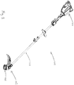
Figure 1 is a perspective view of a power tool in accordance with one embodiment of the present invention; -
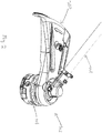
Figure 2 is a close up perspective view of a rotating tool head in accordance with the power tool ofFigure 1 ; -
Figure 3 is a side view of the rotating tool head in accordance with the power tool ofFigure 1 ; -
Figure 4 is an exploded view of the rotating tool head in accordance with the power tool ofFigure 1 ; -
Figure 5 is a rear view of a rotation control arrangement of the rotating tool head ofFigure 4 ; -
Figure 6 is a top perspective view of the rotation control arrangement ofFigure 5 having been coupled to the central hub of the rotating tool head ofFigure 3 ; and -
Figure 7(i) and 7(ii) are block diagrams illustrating the application of torque forces from the motor to the central head during normal operation of the power tool ofFigure 1 and when an opposite force is applied to the central head. - Referring to
Figure 1 , there is illustrated an improvedpower tool 100 comprising: arotating tool head 102 arranged to apply a rotating force to a work surface, wherein the rotating tool head is driven by amotor 104 via a rotation control arrangement arranged to control the rotatingtool head 102 to rotate in one direction only. - In this embodiment, the improved
power tool 100 shown is a string trimmer (also known as a line trimmer). However, as a person skilled in the art would appreciate, the improvedpower tool 100 can be other types of power tools that have a tool head that rotates so as to perform work. These power tools may include drills, trimmers, saws, washers, cutters, diggers, edgers, mowers, shredders, polishers, winch or the like. - In this example, the
line trimmer 100 has a rotatingtool head 102 that includes one or more flexible lines protruding from acentral hub 106. Thetrimmer 100 is arranged to operate by spinning either parts or all of therotating tool head 102 and in turn, when the user directs thetrimmer 100 towards a working surface, the flexible lines that are protruding from thecentral hub 106 would impact vegetation (e.g. grass) or any other objects adjacent to the working surface, resulting in the vegetation or any other protruding objects of suitable characteristics to be cut by the flexible line. - As shown in
Figure 1 , therotating tool head 102 may be driven by amotor 104. Themotor 104 can either be an electric motor, or a gas or gasoline operated motor, although preferably, as shown in this embodiment of the invention, themotor 104 is an electric motor. Thismotor 104 is controlled by a user to rotate and in turn to direct a rotating driving force to the rotatingtool head 102 such that the tool head can apply this rotating force to the work surface. Themotor 104 may be connected to a shaft which is also rotated when the motor is in motion. In turn, when the shaft rotates, the shaft will direct the rotational drive towards the rotatingtool head 102 so as to spin thecentral hub 106 and the flexible lines that protrude from thehub 106. - Preferably, the shaft is flexible and may be made from a generally flexible or torsionally elastic material such as an elastic metal cable or spring cable. Whilst the shaft may not necessarily have to be flexible and in some examples of the invention, the shaft may not be flexible at all, a flexible shaft will allow rotational drive to be directed to different directions without the need for additional gearing or steering mechanisms. In turn, the
shaft housing 108 may be curved or bent so as to enhance the ergonomics or sizing of theline trimmer 100. In addition, as it is shown in the example embodiment ofFigure 1 , the flexibility of the shaft can allow for rotational drive to be directed towards the rotatingtool head 102 by directing the flexible shaft into the rotatingtool head 102 through a joint between theshaft housing 108 and therotating tool head 102 without the need for additional gearing to change the direction of the rotation drive from the shaft to the rotatingtool head 102. - With reference to
Figures 2 ,3 ,4 ,5 and6 , a close up of arotating tool head 102 of one embodiment of the present invention is shown. In this embodiment, the flexible shaft, (which is not shown as it is enveloped within the shaft housing 108) is arranged to rotate during operation as it is driven by themotor 104. In turn, the shaft then transmits this rotation drive towards arotation control arrangement 300 which is arranged to control the rotation of thecentral hub 106 of the rotatingtool head 102 so as to allow thecentral hub 106 to rotate in one direction only. Also shown here in these diagrams is a cuttingguard 202 which shields the user from debris generated from the operation of thetrimmer 100. The cuttingguard 202 does not rotate with thecentral hub 106. - In this example embodiment, the
rotation control arrangement 300 may operate as a rotation transmission mechanism for a power tool comprising: a drive receiving interface arranged to receive a rotational drive delivering shaft connected to a motor operable to provide rotational drive to the power tool; and a drive directing interface arranged to direct the rotational drive to a tool head; wherein the drive receiving interface and the drive directing interface are connected together with a rotation control mechanism arranged to control the rotation of the drive receiving interface or the drive directing interface in a single direction only. In this example, the rotation transmission mechanism effectively works as a transmission interface between the shaft and thecentral hub 106 so as to transmit rotational drive from the shaft to thecentral hub 106 as part of the operation of the power tool. The drive receiving interface may be an engaging plate which is arranged to engage with the shaft, whilst the drive directing interface may be a secondary plate which engages with thecentral hub 106. In between these plates is a drive transfer mechanism which transmits the rotation drive between the drive receiving interface and the drive directing interface. - Preferably, the
rotation control arrangement 300 includes a one way bearing arrangement which physically forces thecentral hub 106 to rotate in one direction only. As shown inFigures 4 ,5 and6 , the one way bearing 300 is arranged to transmit the rotational drive from the shaft to thecentral hub 106 in a single direction. In turn, the one way bearing 300 also physically restricts the rotation of thecentral hub 106 in the opposite direction. - As shown in
Figures 5 and6 , the one way bearing 300 includes a plurality ofrollers 502 which are arranged to make contact with the rotating shaft when the shaft is connected to the oneway bearing 300. When the rotating shaft is rotated, therollers 502 are locked against an outer race of the one way bearing 300 by a mechanical arrangement that may include a sprag and thus allowing the rotation drive from the shaft to drive thecentral hub 106 which may be engaged to the outer race of the oneway bearing 300. Thus in this example embodiment, assuming themotor 104 rotates in a clock wise direction, the one way bearing 300 is locked in the clock wise direction with each of therollers 502 being locked to the outer race of the bearing so as to transfer the rotation drive from themotor 104 to the outer race of thebearing 300. In turn, the outer race of the bearing may then be engaged to thecentral hub 106 and thus rotating thecentral hub 106 with the rotation of thebearing 300. - It is important to note that in this preferred embodiment, a one way bearing 300 is used for the rotation control arrangement. However, other single-direction mechanisms such as a torque convertor, clutch arrangement, ratcheting mechanism or a cam locking system may also be used. A one way bearing 300 has the advantage of being relatively low costs and easy to replace as the bearing will have little or minimal serviceable parts.
- During operation of the
line trimmer 100, thecentral hub 106, which is rotating as it is driven by themotor 104, will move one or more protruding lines extending from thecentral hub 106 to impact with vegetation or other objects so as to cut the vegetation or objects. However, when upon theline trimmer 100 is directed by a user towards a hard object or surface, such as a tree trunk, metal pole or the like or if thecentral hub 106 impacts a ground surface, an impact force may be directed onto thecentral hub 106 itself. In turn, this impact force may slow theline trimmer 100 due to the impact or friction created between thecentral hub 106 and the ground surface. - As shown with reference to
Figure 7(i) and 7(ii) , the impact force that may be experienced in these situations by the trimmer will, at the physical level, cause a force in the opposite direction of the rotation of the central hub. If thecentral hub 702 was rotating in a clockwise direction during its operation, the impact force will effectively apply arotational force 710 in the anti-clockwise direction. - For line trimmers that do not have a rotation control arrangement as described above, this impact force will be transmitted towards the shaft and the motor. In trimmers with a flexible shaft, the shaft will wind up, or become torsionally charged due to the rotational speed differences between the motor and the central hub. One possible result of this wind up or torsional charge is that in electric line trimmers, the wind up or torsional charge will move the rotors of the motor in an opposite direction, against the normal drive of the electric motor. In trimmers which have an electronically controlled direct current (DC) brushless motor, the rotor of the motor may suddenly be out of phase to the electronic control. This is known as back chatter which in turn will reduce the efficiency and effectiveness of the motor. In trimmers which have gasoline engines, the negative torque created by this impact pressure may affect the efficiency of the engine or potentially stall the engine if the torque is sufficient enough.
- With respect to the present embodiments of the invention, the rotation control arrangement which is disposed in between the shaft and the central hub is arranged to physically stop any rotation in the opposite direction. In turn, the rotation control arrangement is able to minimize or reduce any negative rotational force that may be experienced by the central hub from being passed towards the shaft. Thus the possibility of winding by the flexible shaft or the experiences of back chatter by the motor is significantly reduced when the central hub impacts a hard object.
- As illustrated in
Figure 7(i) , during normal operation of an embodiment of the invention, the torque (712) delivered by themotor 708 to the shaft is at 100% clockwise. As theshaft 706 is connected to thecentral hub 702 via a one way bearing 704 in a locked position, the torque (712H) at thecentral hub 702 is also at 100% clockwise, ignoring any torque loss due to friction. - As shown in
Figure 7(ii) , when upon thecentral head 702 of the power tool impacts a surface or hard object, a force (710) in the opposite direction (anti-clockwise) is created as a force that resist the rotation in the clockwise direction. In this example, the anti-clockwise torque (710) is at 10% thus created a net torque (712N) at the head to be 90% in the clockwise position. - However, the
rotation control arrangement 704, which in this example is a one way bearing, is disposed between theshaft 706 and thecentral head 702, and has the characteristic of only allowing rotation in the clockwise direction whilst freewheeling in the anti-clockwise direction. The anti-clockwise torque (710) of 10% is minimized from being transferred towards theshaft 706. Accordingly, as this anti-clockwise torque (710) does not travel upwards pass the one way bearing, the winding of the shaft is thus avoided. Instead, this anti-clockwise torque is likely to be dissipated by the freewheeling of the one way bearing or is absorbed by the components of thebearing 704. In this way, the usage of therotation control arrangement 704 may provide a method for managing back chatter for a power tool, such as a line trimmer, by transmitting rotation drive from a motor to a tool head via a rotational control mechanism arranged to rotate in one direction only. - It will be appreciated by persons skilled in the art that numerous variations and/or modifications may be made to the invention as shown in the specific embodiments without departing from the scope of the invention as claimed. The present embodiments are, therefore, to be considered in all respects as illustrative and not restrictive.
- Any reference to prior art contained herein is not to be taken as an admission that the information is common general knowledge, unless otherwise indicated.
Claims (15)
- An improved power tool (100) comprising:a rotating tool head (102; 702) arranged to apply a rotating force to a work surface and, in turn, impact an object adjacent to the work surface, wherein the rotating tool head (102; 702) is driven by a motor (104; 708) via a rotation control arrangement (300; 704) arranged to control the rotating tool head (102; 702) to rotate in one direction only, despite an impact force being applied to the rotating tool head (102; 702) by said object.
- An improved power tool in accordance with claim 1, wherein the rotation control arrangement (300; 704) is further arranged to transmit rotational drive from the motor (104; 708) to the rotating tool head (102; 702).
- An improved power tool in accordance with claim 2, wherein the rotation control arrangement (300; 704) receives the rotational drive from the motor via a drive shaft (706) arranged to rotatably communicate with the motor.
- An improved power tool in accordance with claim 3, wherein the drive shaft (706) is a flexible drive shaft.
- An improved power tool in accordance with any one of the preceding claims, wherein the rotation control arrangement (300; 704) includes a one way bearing mechanism; and optionally, wherein the one way bearing mechanism is in a locked position when transmitting the rotational drive from the drive shaft (706) to the rotating tool head (102; 702).
- An improved power tool in accordance with claim 3, 4 or 5 when dependent upon claim 3, wherein upon the rotating tool head (102; 702) being subjected to an external force, the external force is resisted from being transmitted towards the drive shaft (706) by the rotation control arrangement (300; 704).
- An improved power tool in accordance with claim 6, wherein the external force is applied to the rotating tool head (102; 702) in a direction opposite to the rotation of the rotating tool head (102; 702); and, optionally, wherein the external force is dissipated by the rotation control arrangement (300; 704).
- An improved power tool in accordance with any one of the preceding claims, wherein the power tool (100) is a line trimmer.
- A rotation transmission mechanism for a power tool (100) comprising:- a drive receiving interface arranged to receive a rotational drive delivering shaft (706) connected to a motor (104; 708) operable to provide rotational drive to the power tool (100); and- a drive directing interface arranged to direct the rotational drive to a rotating tool head (102; 702) arranged to apply a rotating force to a work surface and, in turn, impact an object adjacent to the work surface; wherein the drive receiving interface and the drive directing interface are connected together with a rotation control mechanism (300; 704) arranged to control the rotation of the drive receiving interface or the drive directing interface in a single direction only, despite an impact force being applied to the rotating tool head (102; 702) by said object.
- A rotation transmission mechanism for a power tool in accordance with claim 9, wherein the rotation control mechanism (300; 704) is a one way bearing.
- A rotation transmission mechanism for a power tool in accordance with claim 10, wherein the drive directing interface is arranged to be engaged to the drive receiving interface to transmit the rotational drive from the motor (104; 708) to the rotating tool head (102; 702); and optionally, wherein the drive directing interface is arranged to disengage from the drive receiving interface when rotated in an opposite direction to the rotational drive.
- A rotation transmission mechanism for a power tool in accordance with any one of claims 9 to 11, wherein upon the drive directing interface being subjected to any rotational force in an opposite direction to the rotational drive, the rotation control mechanism (300; 704) is arranged to prevent the rotational force in the opposite direction from being transmitted towards the rotational drive delivering shaft; and, optionally, wherein the rotation control mechanism (300; 704) is arranged to dissipate the rotational force in the opposite direction.
- A rotation transmission mechanism for a power tool in accordance with any one of claims 9 to 12, wherein the rotation transmission mechanism is for a line trimmer.
- A method of managing back chatter for a line trimmer (100) comprising the steps of:- transmitting rotation drive from a motor (104; 708) to a rotating tool head (102; 702) via a rotation control mechanism (300; 704) arranged to rotate in one direction only, wherein the rotating tool head (102; 702) is arranged to apply a rotating force to a work surface and, in turn, impact an object adjacent to the work surface, and wherein the rotation control mechanism (300; 704) is arranged to control the rotating tool head (102; 702) to rotate in one direction only despite an impact force being applied to the rotating tool head (102; 702) by said object.
- A method of managing back chatter for a line trimmer (100) in accordance with claim 14, wherein the rotation control mechanism (300; 704) is a one way bearing; and, optionally, wherein the one way bearing is arranged to lock so as to transmit rotation from the motor (104; 708) to the rotating tool head (105; 702) and is further arranged to resist opposing rotation forces experienced by the tool head (102; 702).
Priority Applications (2)
| Application Number | Priority Date | Filing Date | Title |
|---|---|---|---|
| EP15182735.9A EP3135092B1 (en) | 2015-08-27 | 2015-08-27 | An improved power tool and a rotation transmission mechanism for a power tool |
| CN201610132608.9A CN106475972A (en) | 2015-08-27 | 2016-03-09 | Power tool, rotary transmission mechanism and method for controlling backswing of line trimmer |
Applications Claiming Priority (1)
| Application Number | Priority Date | Filing Date | Title |
|---|---|---|---|
| EP15182735.9A EP3135092B1 (en) | 2015-08-27 | 2015-08-27 | An improved power tool and a rotation transmission mechanism for a power tool |
Publications (2)
| Publication Number | Publication Date |
|---|---|
| EP3135092A1 EP3135092A1 (en) | 2017-03-01 |
| EP3135092B1 true EP3135092B1 (en) | 2018-02-21 |
Family
ID=54012065
Family Applications (1)
| Application Number | Title | Priority Date | Filing Date |
|---|---|---|---|
| EP15182735.9A Active EP3135092B1 (en) | 2015-08-27 | 2015-08-27 | An improved power tool and a rotation transmission mechanism for a power tool |
Country Status (1)
| Country | Link |
|---|---|
| EP (1) | EP3135092B1 (en) |
Family Cites Families (4)
| Publication number | Priority date | Publication date | Assignee | Title |
|---|---|---|---|---|
| US4122601A (en) * | 1976-02-06 | 1978-10-31 | Kaaz Machinery Co., Ltd. | Portable separable grass and bush cutter |
| AU614548B2 (en) * | 1988-10-26 | 1991-09-05 | Tanaka Kogyo Co., Ltd. | Hand-held machine |
| US5954144A (en) * | 1995-06-14 | 1999-09-21 | Intool Incorporated | Variable-speed, multiple-drive power tool |
| US9427859B2 (en) * | 2013-01-08 | 2016-08-30 | Techtrnoic Outdoor Products Technology Limited | Motor system for dual voltage devices |
-
2015
- 2015-08-27 EP EP15182735.9A patent/EP3135092B1/en active Active
Non-Patent Citations (1)
| Title |
|---|
| None * |
Also Published As
| Publication number | Publication date |
|---|---|
| EP3135092A1 (en) | 2017-03-01 |
Similar Documents
| Publication | Publication Date | Title |
|---|---|---|
| EP0365703B1 (en) | Hand-held machine | |
| US10710257B2 (en) | Power tool, such as a metal shears | |
| US11523559B2 (en) | Low-energy blade system having a quick-attach mechanism | |
| US11585394B2 (en) | Work machine | |
| EP3818807A1 (en) | Lawn mower | |
| AU2015101982A4 (en) | An improved power tool and a rotation transmission mechanism for a power tool | |
| EP2281430B1 (en) | Vegetation cutting tool with trimming and edging positions | |
| EP3135092A1 (en) | An improved power tool and a rotation transmission mechanism for a power tool | |
| GB2302067A (en) | Prime mover for tools, light, or starter | |
| AU2015218506A1 (en) | An improved power tool and a rotation transmission mechanism for a power tool | |
| CN103486150A (en) | Protection clutch | |
| CN106475972A (en) | Power tool, rotary transmission mechanism and method for controlling backswing of line trimmer | |
| CN117156967B (en) | Power-enhancing fasteners for power tools and equipment | |
| US20070084612A1 (en) | Rotary cultivator | |
| CN212588944U (en) | A transmission structure and weeder for weeder | |
| JPH052051Y2 (en) | ||
| EP1106044B1 (en) | Portable handeled tool for use in farming and gardening works provided with an improved handle | |
| JPH0711922Y2 (en) | Power work machine | |
| JPS6016522A (en) | brush cutter | |
| KR20160084893A (en) | Bush cutting machine |
Legal Events
| Date | Code | Title | Description |
|---|---|---|---|
| PUAI | Public reference made under article 153(3) epc to a published international application that has entered the european phase |
Free format text: ORIGINAL CODE: 0009012 |
|
| AK | Designated contracting states |
Kind code of ref document: A1 Designated state(s): AL AT BE BG CH CY CZ DE DK EE ES FI FR GB GR HR HU IE IS IT LI LT LU LV MC MK MT NL NO PL PT RO RS SE SI SK SM TR |
|
| AX | Request for extension of the european patent |
Extension state: BA ME |
|
| 17P | Request for examination filed |
Effective date: 20170725 |
|
| RBV | Designated contracting states (corrected) |
Designated state(s): AL AT BE BG CH CY CZ DE DK EE ES FI FR GB GR HR HU IE IS IT LI LT LU LV MC MK MT NL NO PL PT RO RS SE SI SK SM TR |
|
| RAP1 | Party data changed (applicant data changed or rights of an application transferred) |
Owner name: TTI (MACAO COMMERCIAL OFFSHORE) LIMITED |
|
| GRAP | Despatch of communication of intention to grant a patent |
Free format text: ORIGINAL CODE: EPIDOSNIGR1 |
|
| INTG | Intention to grant announced |
Effective date: 20171208 |
|
| GRAS | Grant fee paid |
Free format text: ORIGINAL CODE: EPIDOSNIGR3 |
|
| GRAA | (expected) grant |
Free format text: ORIGINAL CODE: 0009210 |
|
| AK | Designated contracting states |
Kind code of ref document: B1 Designated state(s): AL AT BE BG CH CY CZ DE DK EE ES FI FR GB GR HR HU IE IS IT LI LT LU LV MC MK MT NL NO PL PT RO RS SE SI SK SM TR |
|
| REG | Reference to a national code |
Ref country code: GB Ref legal event code: FG4D |
|
| REG | Reference to a national code |
Ref country code: CH Ref legal event code: EP |
|
| REG | Reference to a national code |
Ref country code: AT Ref legal event code: REF Ref document number: 970691 Country of ref document: AT Kind code of ref document: T Effective date: 20180315 |
|
| REG | Reference to a national code |
Ref country code: IE Ref legal event code: FG4D |
|
| REG | Reference to a national code |
Ref country code: DE Ref legal event code: R096 Ref document number: 602015008138 Country of ref document: DE |
|
| REG | Reference to a national code |
Ref country code: NL Ref legal event code: MP Effective date: 20180221 |
|
| REG | Reference to a national code |
Ref country code: LT Ref legal event code: MG4D |
|
| REG | Reference to a national code |
Ref country code: AT Ref legal event code: MK05 Ref document number: 970691 Country of ref document: AT Kind code of ref document: T Effective date: 20180221 |
|
| PG25 | Lapsed in a contracting state [announced via postgrant information from national office to epo] |
Ref country code: FI Free format text: LAPSE BECAUSE OF FAILURE TO SUBMIT A TRANSLATION OF THE DESCRIPTION OR TO PAY THE FEE WITHIN THE PRESCRIBED TIME-LIMIT Effective date: 20180221 Ref country code: NO Free format text: LAPSE BECAUSE OF FAILURE TO SUBMIT A TRANSLATION OF THE DESCRIPTION OR TO PAY THE FEE WITHIN THE PRESCRIBED TIME-LIMIT Effective date: 20180521 Ref country code: LT Free format text: LAPSE BECAUSE OF FAILURE TO SUBMIT A TRANSLATION OF THE DESCRIPTION OR TO PAY THE FEE WITHIN THE PRESCRIBED TIME-LIMIT Effective date: 20180221 Ref country code: HR Free format text: LAPSE BECAUSE OF FAILURE TO SUBMIT A TRANSLATION OF THE DESCRIPTION OR TO PAY THE FEE WITHIN THE PRESCRIBED TIME-LIMIT Effective date: 20180221 Ref country code: ES Free format text: LAPSE BECAUSE OF FAILURE TO SUBMIT A TRANSLATION OF THE DESCRIPTION OR TO PAY THE FEE WITHIN THE PRESCRIBED TIME-LIMIT Effective date: 20180221 Ref country code: NL Free format text: LAPSE BECAUSE OF FAILURE TO SUBMIT A TRANSLATION OF THE DESCRIPTION OR TO PAY THE FEE WITHIN THE PRESCRIBED TIME-LIMIT Effective date: 20180221 Ref country code: CY Free format text: LAPSE BECAUSE OF FAILURE TO SUBMIT A TRANSLATION OF THE DESCRIPTION OR TO PAY THE FEE WITHIN THE PRESCRIBED TIME-LIMIT Effective date: 20180221 |
|
| REG | Reference to a national code |
Ref country code: FR Ref legal event code: PLFP Year of fee payment: 4 |
|
| PG25 | Lapsed in a contracting state [announced via postgrant information from national office to epo] |
Ref country code: BG Free format text: LAPSE BECAUSE OF FAILURE TO SUBMIT A TRANSLATION OF THE DESCRIPTION OR TO PAY THE FEE WITHIN THE PRESCRIBED TIME-LIMIT Effective date: 20180521 Ref country code: RS Free format text: LAPSE BECAUSE OF FAILURE TO SUBMIT A TRANSLATION OF THE DESCRIPTION OR TO PAY THE FEE WITHIN THE PRESCRIBED TIME-LIMIT Effective date: 20180221 Ref country code: SE Free format text: LAPSE BECAUSE OF FAILURE TO SUBMIT A TRANSLATION OF THE DESCRIPTION OR TO PAY THE FEE WITHIN THE PRESCRIBED TIME-LIMIT Effective date: 20180221 Ref country code: LV Free format text: LAPSE BECAUSE OF FAILURE TO SUBMIT A TRANSLATION OF THE DESCRIPTION OR TO PAY THE FEE WITHIN THE PRESCRIBED TIME-LIMIT Effective date: 20180221 Ref country code: GR Free format text: LAPSE BECAUSE OF FAILURE TO SUBMIT A TRANSLATION OF THE DESCRIPTION OR TO PAY THE FEE WITHIN THE PRESCRIBED TIME-LIMIT Effective date: 20180522 Ref country code: AT Free format text: LAPSE BECAUSE OF FAILURE TO SUBMIT A TRANSLATION OF THE DESCRIPTION OR TO PAY THE FEE WITHIN THE PRESCRIBED TIME-LIMIT Effective date: 20180221 |
|
| PG25 | Lapsed in a contracting state [announced via postgrant information from national office to epo] |
Ref country code: PL Free format text: LAPSE BECAUSE OF FAILURE TO SUBMIT A TRANSLATION OF THE DESCRIPTION OR TO PAY THE FEE WITHIN THE PRESCRIBED TIME-LIMIT Effective date: 20180221 Ref country code: EE Free format text: LAPSE BECAUSE OF FAILURE TO SUBMIT A TRANSLATION OF THE DESCRIPTION OR TO PAY THE FEE WITHIN THE PRESCRIBED TIME-LIMIT Effective date: 20180221 Ref country code: AL Free format text: LAPSE BECAUSE OF FAILURE TO SUBMIT A TRANSLATION OF THE DESCRIPTION OR TO PAY THE FEE WITHIN THE PRESCRIBED TIME-LIMIT Effective date: 20180221 Ref country code: IT Free format text: LAPSE BECAUSE OF FAILURE TO SUBMIT A TRANSLATION OF THE DESCRIPTION OR TO PAY THE FEE WITHIN THE PRESCRIBED TIME-LIMIT Effective date: 20180221 Ref country code: RO Free format text: LAPSE BECAUSE OF FAILURE TO SUBMIT A TRANSLATION OF THE DESCRIPTION OR TO PAY THE FEE WITHIN THE PRESCRIBED TIME-LIMIT Effective date: 20180221 |
|
| REG | Reference to a national code |
Ref country code: DE Ref legal event code: R097 Ref document number: 602015008138 Country of ref document: DE |
|
| PG25 | Lapsed in a contracting state [announced via postgrant information from national office to epo] |
Ref country code: CZ Free format text: LAPSE BECAUSE OF FAILURE TO SUBMIT A TRANSLATION OF THE DESCRIPTION OR TO PAY THE FEE WITHIN THE PRESCRIBED TIME-LIMIT Effective date: 20180221 Ref country code: SK Free format text: LAPSE BECAUSE OF FAILURE TO SUBMIT A TRANSLATION OF THE DESCRIPTION OR TO PAY THE FEE WITHIN THE PRESCRIBED TIME-LIMIT Effective date: 20180221 Ref country code: SM Free format text: LAPSE BECAUSE OF FAILURE TO SUBMIT A TRANSLATION OF THE DESCRIPTION OR TO PAY THE FEE WITHIN THE PRESCRIBED TIME-LIMIT Effective date: 20180221 Ref country code: DK Free format text: LAPSE BECAUSE OF FAILURE TO SUBMIT A TRANSLATION OF THE DESCRIPTION OR TO PAY THE FEE WITHIN THE PRESCRIBED TIME-LIMIT Effective date: 20180221 |
|
| PLBE | No opposition filed within time limit |
Free format text: ORIGINAL CODE: 0009261 |
|
| STAA | Information on the status of an ep patent application or granted ep patent |
Free format text: STATUS: NO OPPOSITION FILED WITHIN TIME LIMIT |
|
| 26N | No opposition filed |
Effective date: 20181122 |
|
| PG25 | Lapsed in a contracting state [announced via postgrant information from national office to epo] |
Ref country code: SI Free format text: LAPSE BECAUSE OF FAILURE TO SUBMIT A TRANSLATION OF THE DESCRIPTION OR TO PAY THE FEE WITHIN THE PRESCRIBED TIME-LIMIT Effective date: 20180221 |
|
| PG25 | Lapsed in a contracting state [announced via postgrant information from national office to epo] |
Ref country code: MC Free format text: LAPSE BECAUSE OF FAILURE TO SUBMIT A TRANSLATION OF THE DESCRIPTION OR TO PAY THE FEE WITHIN THE PRESCRIBED TIME-LIMIT Effective date: 20180221 |
|
| REG | Reference to a national code |
Ref country code: CH Ref legal event code: PL |
|
| PG25 | Lapsed in a contracting state [announced via postgrant information from national office to epo] |
Ref country code: CH Free format text: LAPSE BECAUSE OF NON-PAYMENT OF DUE FEES Effective date: 20180831 Ref country code: LI Free format text: LAPSE BECAUSE OF NON-PAYMENT OF DUE FEES Effective date: 20180831 Ref country code: LU Free format text: LAPSE BECAUSE OF NON-PAYMENT OF DUE FEES Effective date: 20180827 |
|
| REG | Reference to a national code |
Ref country code: BE Ref legal event code: MM Effective date: 20180831 |
|
| REG | Reference to a national code |
Ref country code: DE Ref legal event code: R082 Ref document number: 602015008138 Country of ref document: DE Representative=s name: MARKS & CLERK (LUXEMBOURG) LLP, LU Ref country code: DE Ref legal event code: R081 Ref document number: 602015008138 Country of ref document: DE Owner name: TECHTRONIC OUTDOOR PRODUCTS TECHNOLOGY LIMITED, BM Free format text: FORMER OWNER: TTI (MACAO COMMERCIAL OFFSHORE) LTD., MACAO, MO |
|
| PG25 | Lapsed in a contracting state [announced via postgrant information from national office to epo] |
Ref country code: BE Free format text: LAPSE BECAUSE OF NON-PAYMENT OF DUE FEES Effective date: 20180831 |
|
| REG | Reference to a national code |
Ref country code: GB Ref legal event code: 732E Free format text: REGISTERED BETWEEN 20190829 AND 20190904 |
|
| PG25 | Lapsed in a contracting state [announced via postgrant information from national office to epo] |
Ref country code: MT Free format text: LAPSE BECAUSE OF NON-PAYMENT OF DUE FEES Effective date: 20180827 |
|
| PG25 | Lapsed in a contracting state [announced via postgrant information from national office to epo] |
Ref country code: TR Free format text: LAPSE BECAUSE OF FAILURE TO SUBMIT A TRANSLATION OF THE DESCRIPTION OR TO PAY THE FEE WITHIN THE PRESCRIBED TIME-LIMIT Effective date: 20180221 |
|
| PG25 | Lapsed in a contracting state [announced via postgrant information from national office to epo] |
Ref country code: PT Free format text: LAPSE BECAUSE OF FAILURE TO SUBMIT A TRANSLATION OF THE DESCRIPTION OR TO PAY THE FEE WITHIN THE PRESCRIBED TIME-LIMIT Effective date: 20180221 |
|
| PG25 | Lapsed in a contracting state [announced via postgrant information from national office to epo] |
Ref country code: IE Free format text: LAPSE BECAUSE OF NON-PAYMENT OF DUE FEES Effective date: 20180827 Ref country code: MK Free format text: LAPSE BECAUSE OF NON-PAYMENT OF DUE FEES Effective date: 20180221 Ref country code: HU Free format text: LAPSE BECAUSE OF FAILURE TO SUBMIT A TRANSLATION OF THE DESCRIPTION OR TO PAY THE FEE WITHIN THE PRESCRIBED TIME-LIMIT; INVALID AB INITIO Effective date: 20150827 |
|
| PG25 | Lapsed in a contracting state [announced via postgrant information from national office to epo] |
Ref country code: IS Free format text: LAPSE BECAUSE OF FAILURE TO SUBMIT A TRANSLATION OF THE DESCRIPTION OR TO PAY THE FEE WITHIN THE PRESCRIBED TIME-LIMIT Effective date: 20180621 |
|
| PGFP | Annual fee paid to national office [announced via postgrant information from national office to epo] |
Ref country code: DE Payment date: 20250827 Year of fee payment: 11 |
|
| PGFP | Annual fee paid to national office [announced via postgrant information from national office to epo] |
Ref country code: GB Payment date: 20250827 Year of fee payment: 11 |
|
| PGFP | Annual fee paid to national office [announced via postgrant information from national office to epo] |
Ref country code: FR Payment date: 20250825 Year of fee payment: 11 |