EP3134665B1 - Piston seal assembly with controlled leakage - Google Patents
Piston seal assembly with controlled leakage Download PDFInfo
- Publication number
- EP3134665B1 EP3134665B1 EP15769025.6A EP15769025A EP3134665B1 EP 3134665 B1 EP3134665 B1 EP 3134665B1 EP 15769025 A EP15769025 A EP 15769025A EP 3134665 B1 EP3134665 B1 EP 3134665B1
- Authority
- EP
- European Patent Office
- Prior art keywords
- seal
- lateral surface
- piston
- energizer
- seal energizer
- Prior art date
- Legal status (The legal status is an assumption and is not a legal conclusion. Google has not performed a legal analysis and makes no representation as to the accuracy of the status listed.)
- Active
Links
Images





Classifications
-
- F—MECHANICAL ENGINEERING; LIGHTING; HEATING; WEAPONS; BLASTING
- F04—POSITIVE - DISPLACEMENT MACHINES FOR LIQUIDS; PUMPS FOR LIQUIDS OR ELASTIC FLUIDS
- F04B—POSITIVE-DISPLACEMENT MACHINES FOR LIQUIDS; PUMPS
- F04B53/00—Component parts, details or accessories not provided for in, or of interest apart from, groups F04B1/00 - F04B23/00 or F04B39/00 - F04B47/00
- F04B53/02—Packing the free space between cylinders and pistons
-
- F—MECHANICAL ENGINEERING; LIGHTING; HEATING; WEAPONS; BLASTING
- F16—ENGINEERING ELEMENTS AND UNITS; GENERAL MEASURES FOR PRODUCING AND MAINTAINING EFFECTIVE FUNCTIONING OF MACHINES OR INSTALLATIONS; THERMAL INSULATION IN GENERAL
- F16J—PISTONS; CYLINDERS; SEALINGS
- F16J9/00—Piston-rings, e.g. non-metallic piston-rings, seats therefor; Ring sealings of similar construction
- F16J9/06—Piston-rings, e.g. non-metallic piston-rings, seats therefor; Ring sealings of similar construction using separate springs or elastic elements expanding the rings; Springs therefor ; Expansion by wedging
- F16J9/061—Piston-rings, e.g. non-metallic piston-rings, seats therefor; Ring sealings of similar construction using separate springs or elastic elements expanding the rings; Springs therefor ; Expansion by wedging using metallic coiled or blade springs
- F16J9/063—Strip or wire along the entire circumference
-
- F—MECHANICAL ENGINEERING; LIGHTING; HEATING; WEAPONS; BLASTING
- F16—ENGINEERING ELEMENTS AND UNITS; GENERAL MEASURES FOR PRODUCING AND MAINTAINING EFFECTIVE FUNCTIONING OF MACHINES OR INSTALLATIONS; THERMAL INSULATION IN GENERAL
- F16J—PISTONS; CYLINDERS; SEALINGS
- F16J9/00—Piston-rings, e.g. non-metallic piston-rings, seats therefor; Ring sealings of similar construction
- F16J9/12—Details
- F16J9/14—Joint-closures
- F16J9/145—Joint-closures of spring expanders
Definitions
- the present disclosure relates to a reciprocating pump comprising a piston seal assembly with controlled leakage.
- Pistons which reciprocate within a cylinder bore are well known in the art and have been long used for pumps, hydraulic drives, engines, pneumatic drives and other hydraulic or pneumatic machines delivering different fluids at increased pressure.
- a piston seal assembly is employed for dynamic sealing to prevent fluid from leaking between the piston and the cylinder walls.
- Piston seals are subjected to substantive wear due to the piston's movement within the cylinder bore and sometimes they fail due to excessive wear and/or due to the stress caused by the pressure exerted on the seal by the fluid being compressed. Such operating conditions can be even more challenging in the case of high pressure reciprocating pumps and/or in the case of pumps handling cryogenic fluids.
- An example of such a reciprocating pump is a pump used to deliver a liquefied gaseous fuel from a cryogenic vessel to a gaseous-fuelled internal combustion engine.
- Such pumps can handle fluids at relatively high pressures, around 4600 psi, and at low temperatures, for example at around -130 degrees Celsius and lower. It is difficult to provide an effective seal for the piston of such a pump especially because the material of the seal has to withstand the low temperatures of the pumped fluid and the high compression stresses acting on the seal. Also, the different contraction coefficients of the materials from which the pump components and the seals are made can result in gaps being formed between the piston seals and the cylinder wall allowing fluid to leak from the compression chamber past the piston seal to the low pressure side of the pump.
- split seals have been used to address the seal wear problem.
- Split seals have the shape of a ring having a cut which allows it to be installed on the piston and more importantly it allows the seal to expand to compensate for the seal wear.
- a seal energizer is provided for supporting the seal and pushing it towards the cylinder wall.
- the seal energizer can be a metal ring that is positioned underneath the seal and forms together with the seal a piston seal assembly that is placed in a piston groove.
- the seal energizer is split transversally such that there is a gap between the free ends of the ring which provides for an easier installation of the seal energizer in the piston groove and provides more elastic force for pushing the seal towards the cylinder wall when the seal assembly is installed in the piston groove.
- the seal leak path area can vary depending on the manufacturing tolerances of the seal energizer and of the piston groove and depending on the pump's operating conditions.
- seal assemblies each comprising a seal and a seal energizer
- some seals show substantially more wear than others with at least one random seal failing after some time. This can be explained by the fact that the pressure drop across each seal varies. The pressure drop across each seal depends on the size of the leak path area through the seal, and seals with the smallest leak path area experience the greatest pressure drop due to the highest resistance to fluid pressure and will wear faster. The replacement of worn seals requires taking the apparatus out of service, removing the piston and replacing the seals.
- US2785029 discloses a combined expander, side pressure spring and oil ventilator which may be used with a plain unvented compression ring in a lower oil groove of a piston for conserving and salvaging lubricating oil in engines.
- US1911735 discloses a piston ring.
- US3477732 discloses a spacer-expander.
- the present invention provides a reciprocating pump as recited in claim 1.
- the disclosed apparatus was developed for piston seals for reciprocating cryogenic piston pumps which have some particular characteristics which require improved design features.
- the improved seal assembly is described herein in the context of this application. Nevertheless the teachings of the disclosed apparatus can be applied to improve seal life for many different applications for reciprocating pumps comprising piston seal assemblies that employ a piston ring seal and seal energizer.
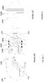
- Figure 1 illustrates a reciprocating pump 110, known in the prior art, which comprises a cylinder bore 120, defined by the body of the pump, and a piston 130 which is actuated by an actuating mechanism (not illustrated) through a shaft 133 such that it has a reciprocating movement D within cylinder bore 120.
- piston 130 moves in one direction it draws in fluid into compression chamber 150 through the pump's intake port, during the intake stroke, and when piston 130 moves in the opposite direction, it compresses the fluid within compression chamber 150 during the compression stroke of the pump.
- Piston 130 comprises a series of seal assemblies 100A, 100B and 100C.
- Each seal assembly comprises a seal and a seal energizer supporting the seal, which are better illustrated in Figures 3 , 4A , 4B and 4C .
- Each seal can have a split configuration as illustrated Figure 2 and further detailed in Figure 3 .
- the type of seal energizer illustrated in Figures 1 and 3 is known in the prior art and is generally provided for seal assemblies comprising a split seal, more commonly known as an "S-cut" seal, to allow the seal to remain in close proximity to the cylinder wall when the outer circumferential surface is worn, thereby maintaining a good seal between the piston and the cylinder wall.
- Each split seal 160A, 160B and 160C has two overlapping free end segments.
- Figure 3 illustrates a view of the outer circumferential surface of seal assembly 100A which comprises seal 160A and underlying seal energizer 180A.
- Seal 160A has two overlapping end segments, a first end segment 112A and a second end segment 114A, each having a width that is smaller than the width of the main body of the seal.
- Seal 160A is supported by seal energizer 180A and the seal assembly formed by the seal and the seal energizer is located in a circumferential piston groove 190A, formed in the piston, as better illustrated in Figures 4A, 4B and 4C .
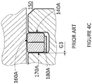
- Figure 4A which shows a piston assembly comprising seal 160A and seal energizer 180A positioned in piston groove 190A
- seal energizer 180A is positioned closer to the groove wall 140A that is closer to the higher pressure side of the piston, which is the side closer to the compression chamber 150
- the leak path between the seal energizer and the groove wall 170A which is closer to the low pressure side of the piston, allows a bigger gap G1 and implicitly a larger leak area compared to leak path through the seal assembly when seal energizer 180A is positioned axially in the centre of groove 190A, as illustrated in Figure 4B where gap G2 is smaller than G1, or if seal energizer 180A is positioned closer to groove wall 170A, as illustrated in Figure 4C where gap G3 is the smallest.
- the seal energizer is consistently positioned in the piston groove such that one of its lateral surfaces is in contact with the piston groove wall that is closer to the lower pressure side of the piston which allows the smallest leak path area for any fluid leaking from the high pressure side of the piston, as illustrated in Figure 4C .
- Seal energizer 280 is in the shape of a split ring comprising an outer circumferential surface 281, an inner circumferential surface 282, a first lateral surface 283 and a second lateral surface 284, adjoining the outer and inner circumferential surfaces and it comprises a gap 285 between the free ends of the split ring.
- Piston seal assembly 200 comprises seal 260 and seal energizer 280 whose outer circumferential surface 281 supports seal 260.
- Piston seal assembly is installed in piston groove 290 of piston 230.
- Seal 260 is generally a split seal and more particularly an S-cut seal as shown in Figures 2 and 3 .
- first lateral surface 283 of seal energizer 280 is provided with a plurality of tabs 286 extending in a direction perpendicular to the first lateral surface and positioned at predetermined spaced intervals along the first lateral surface of seal energizer 280.
- Figure 5A illustrates a seal energizer with four tabs 286 spaced evenly along first lateral surface 283 of the seal energizer.
- the seal energizer can be provided with any number of tabs, including just one tab.
- Seal energizer 280 is placed in piston groove 290 with its first lateral surface 283 which is provided with tabs 286 facing groove wall 270 that is closer to compression chamber 250 which is the higher pressure side of piston 230; and facing away from groove wall 240 that is closer to the lower side of the piston. Because only tabs 286 come in contact with wall 270 of the piston groove the manufacturing tolerance requirements for the first lateral surface of the seal energizer are less strict and only the surfaces of the tabs that are facing the groove wall need to be manufactured within tight tolerances to ensure a fixed axial position of the energizer within the piston groove.
- Seal energizer 380 has the shape of split ring comprising an outer circumferential surface 381, an inner circumferential surface 382, a first lateral surface 383 and a second lateral surface 384, adjoining the outer and inner circumferential surfaces and it comprises a gap 385 between the free ends of the split ring.
- Piston seal assembly 300 comprises a seal 360 and seal energizer 380 whose outer circumferential surface 381 supports the seal, and is installed in piston groove 390 of piston 330.
- Seal 360 is generally a split seal or an S-cut seal that can have the shape illustrated in Figures 2 and 3 .
- first lateral surface 383 of seal energizer 380 is provided with a plurality of tabs 386 extending in a direction perpendicular to the first lateral surface 383 and a plurality of tabs 387 extending in a direction perpendicular to the lateral surface 384.
- Figure 6A illustrates a seal energizer with four tabs 386 spread evenly along first lateral surface 383 of the seal energizer and with four tabs 387, with each tab 387 having its axis aligned with the axis of its corresponding tab 386, such that they substantially share a common axis 388.
- the seal energizer can be provided with any number of tabs, including only one tab on each of the lateral surfaces of the seal energizer and that preferably it comprises at least three tabs 386 equally spaced along the first lateral surface of the seal energizer and at least three corresponding tabs 387 spaced along the second lateral surface of the seal energizer.
- the tabs on one lateral surface of the seal energizer don't have to be aligned with the tabs on the other lateral surface of the seal energizer as long as they are distributed to ensure a stable position of the seal energizer within the piston groove.
- seal energizer 380 is placed in piston groove 390 with first lateral surface 383 provided with tabs 386 facing groove wall 370 that is closer to compression chamber 350 and with second lateral surface 384 provided with tabs 387 facing groove wall 340 that is closer to the lower side of the piston.
- first lateral surface 383 provided with tabs 386 facing groove wall 370 that is closer to compression chamber 350
- second lateral surface 384 provided with tabs 387 facing groove wall 340 that is closer to the lower side of the piston.
- tabs 387 can have a different width and depth than tabs 386 and preferably tabs 387 on the lateral surface of the seal energizer that is closer to the lower pressure side of the piston have a smaller height than the tabs on the other lateral surface of the seal energizer to minimize the leak path area through gap G2. Because only tabs 386 and 387 come in contact with wall 370 and respectively wall 340 of the piston groove, the manufacturing tolerance requirements for the lateral surfaces of the seal energizer are less strict and only the surfaces of the tabs that are facing the groove wall need to be manufactured within tight tolerances. Especially tabs 387 which contact wall 340 closer to the lower pressure side of the pump have to have a tightly controlled height because their height controls the size of gap G2.
- the axial positioning of the seal energizer within the piston groove illustrated in Figure 6B is similar with the one illustrated in Figure 4B .
- the leak path area corresponding to gap G2 in this second embodiment is slightly larger than the leak path area corresponding to gap G1 illustrated in Figure 5B , but this second embodiment can enable an easier installation and assembly process of the seal assembly, while maintaining a controlled leak through the seal assembly.
- Tabs 386 and 387 are illustrated having a rectangular shape, but they can also have a rounded or semicircular shape or any other shape that allows an appropriate contact surface with the wall of the piston groove where the seal energizer is positioned.
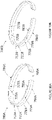
- Figure 7A illustrates a third embodiment of the seal energizer.
- Seal energizer 480A has a similar construction with the seal energizer of the first embodiment illustrated in Figure 5A . It has the shape of split ring comprising an outer circumferential surface 481A, an inner circumferential surface 482A, a first lateral surface 483A and a second lateral surface 484A, adjoining the outer and inner circumferential surfaces and it comprises a gap 485A between the free ends of the split ring.
- First lateral surface 483A of seal energizer 480A is provided with a plurality of tabs 486A extending in a direction perpendicular to the first lateral surface and positioned at predetermined spaced intervals along the first lateral surface of the seal energizer.
- Figure 7 illustrates a seal energizer with seven tabs 486A spread evenly along first lateral surface 483A of the seal energizer.
- the seal energizer can be provided with any number of tabs and that preferably it comprises at least three tabs equally spaced along the first lateral surface of the seal energizer so that the tabs ensure a stable axial position of the seal energizer within the piston groove.
- tabs 486A which extend from surface 483A of the seal energizer are preferably made from a compliant material which has a low thermal expansion coefficient.
- the tabs are fitted into notches 451A provided in the first lateral surface 483A of the seal energizer and are illustrated as having a semicircular surface.
- the tabs can be injection molded into the notches provided in the seal energizer or they can be manufactured separately by any method known in the art and then inserted into the corresponding notches provided in the seal energizer.
- the tabs can be made of the same material as the seal energizer or of a softer, more elastic material than the material of the seal energizer, for example an elastomeric or a plastic material.
- tabs 486A can have a rectangular shape, similar with the tabs illustrated in Figure 5A , or any other shape that allows an appropriate contact surface with the wall of the piston groove where the seal energizer is positioned.
- Seal energizer 480A is placed in a piston groove in a similar way as the seal energizer 280 of the first embodiment, as illustrated in Figure 5B .
- first lateral surface 483A provided with tabs 486A faces the groove wall that is closer to the higher pressure side of the pump piston. Because tabs 486A are made of a compliant material there is no requirement regarding tight manufacturing tolerances of the tabs.
- the seal energizer is positioned within the piston groove the tabs are pressed against the wall of the groove thereby positioning the seal energizer in a fixed axial position within the groove.
- the axial positioning of the seal energizer within the piston groove is similar with the one illustrated in Figure 5B and such arrangement ensures a reduced leak path area through the piston seal assembly.
- lateral surface 483B of seal energizer 480B is provided with notches 451B and seal energizer 480B comprises a component 489B which is provided with tabs 486B, fitted in these notches, and with connecting portions 441B between these tabs. It has the shape of a split ring comprising an outer circumferential surface 481B, an inner circumferential surface 482B, a first lateral surface 483B and a second lateral surface 484B, adjoining the outer and inner circumferential surfaces and it comprises a gap 485B between the free ends of the split ring.
- Component 489B can be manufactured separately by any method known in the art, and then fitted on the lateral surface 483B of the seal energizer with tabs 486B inserted in notches 451B.
- Component 489B can be made of the same material as the seal energizer or of softer, more elastic material than the material of the seal energizer, for example an elastomeric or plastic material.
- Seal energizer 580 has the shape of split ring comprising an outer circumferential surface 581, an inner circumferential surface 582, a first lateral surface 583 and a second lateral surface 584, adjoining the outer and inner circumferential surfaces and it comprises a gap 585 between the free ends of the split ring.
- first and second lateral surfaces of the seal energizer are curved the curvature of these two surfaces being defined by an angle ⁇ and respectively ⁇ .
- Angles ⁇ and ⁇ are the angles defined by the respective lateral surface of the seal energizer and a straight planar surface perpendicular on the axis A-A of the seal energizer.
- piston seal assembly 500 comprises seal 560 and seal energizer 580 whose outer circumferential surface 581 supports the seal and is installed in piston groove 590 of piston 530.
- Seal 560 is generally a split seal that can have an S-cut as illustrated in Figures 2 and 3 .
- Seal energizer 580 is preferably positioned within piston groove 590 such that in the area of the S-cut, more specifically in the area where the free ends of the seal are overlapping, second lateral surface 584 comes into contact with groove wall 540, as illustrated in Figure 8B .
- Figure 8C illustrates the position of the seal energizer in a cross-section through the piston seal assembly along a plane that is positioned at a 90 degree angle relative to the cross-sectional view illustrated in Figure 8B .
- first lateral surface 583 comes into contact with groove wall 570 that is closer to the high pressure side 550 of the piston.
- the leak path between the seal energizer and the groove wall 540 that is closer to the low pressure side of the piston allows a bigger gap G1 and implicitly a larger leak area, but this portion of the seal energizer is not positioned underneath the area where the free ends of the seal are overlapping and where the potential of fluid leaking past the seal assembly is higher.
- seal energizer 580 and seal 560 it is preferred to have a fixed relative position between seal energizer 580 and seal 560 such that the reduced leak area through the piston seal assembly corresponds to the area where the free ends of the seal are overlapping.
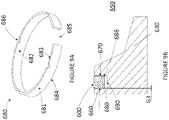
- Seal energizer 680 has the shape of split ring comprising an outer circumferential surface 681, an inner circumferential surface 682, a first lateral surface 683 and a second lateral surface 684, adjoining the outer and inner circumferential surfaces and it comprises a gap 685 between the free ends of the split ring.
- Piston seal assembly 600 comprises seal 660 and seal energizer 680 whose outer circumferential surface 681 supports the seal and is installed in piston groove 690 of piston 630.
- Seal 660 is generally a split seal or an S-cut seal that can have the shape illustrated in Figures 2 and 3 .
- first lateral surface 683 of seal energizer 680 is provided with a plurality of recesses 686 positioned at predetermined intervals along the first lateral surface of the seal energizer.
- Figure 9A illustrates a seal energizer with four recesses 686 spread evenly along first lateral surface 683 of the seal energizer.
- the seal energizer can be provided with a different number of recesses, with at least one recess being provided on one of the lateral surfaces of the seal energizer.
- the recesses illustrated in Figure 9A have a semicircular shape, but a person skilled in the art would recognize that the recesses provided on the surface of the seal energizer can be of any other shapes.
- Seal energizer 680 is placed in piston groove 690 with first lateral surface 683 provided with recesses 686 facing groove wall 670 that is closer to compression chamber 650.
- the manufacturing tolerance requirements for the first and second lateral surfaces of the seal energizer are stricter to ensure a fixed axial position of the energizer within the piston groove.
- the depth of the recesses on the lateral surface of the seal energizer closer to the higher pressure side of the piston has to be controlled through manufacturing tolerances to be more precise such that it allows a better control of the leak area through the piston seal assembly.
- Figures 10A and 10B show the views of another embodiments of a seal energizer disclosed here.
- Seal energizer 780A made of two parts 711A and 713A which are positioned next to each other and share a common longitudinal axis when the seal energizer is placed in a piston groove.
- First part 711A has an outer circumferential surface 771A and an inner circumferential surface 775A
- second part 713A has an outer circumferential surface 773A and an inner circumferential surface 777A which form together the outer circumferential surface of the seal energizer with gap 785A which supports the seal of the piston seal assembly and respectively the inner circumferential surface of the seal energizer which faces the piston groove wall when seal energizer 780A is placed in the piston groove.
- Part 713A has a lateral surface which is the first lateral surface 783A of the seal energizer and it is shaped to position the seal energizer in a fixed axial position within the piston groove.
- first lateral surface 783A is provided with several tabs 786A which extend in a direction perpendicular to the first lateral surface such that when seal energizer 780A is placed in a piston groove tabs 786A are in contact with a wall of the piston groove to position the seal energizer in a fixed axial position within the piston groove in a similar manner as illustrated in Figure 5B and explained in more detail in relation to the first embodiment of the present disclosure.
- seal energizer 780A can have a shape similar to the one illustrated in Figure 6A where both the first lateral surface 783A and the second lateral surface 784A can be provided with tabs and that in this variant seal energizer 780A could be made, for example, of two or three parts having a common longitudinal axis when positioned next to each other in the piston groove.
- seal energizer 780B is made of two parts 711B and 713B which are positioned next to each other and share a common longitudinal axis when the seal energizer is placed in a piston groove.
- seal energizer 780B is made of two parts 711B and 713B which are positioned next to each other and share a common longitudinal axis when the seal energizer is placed in a piston groove.
- part 713B is made of a more compliant material than the material of part 711B, for example an elastomeric or plastic material, and it is dimensioned to position seal energizer 780B in a fixed axial position within the piston groove.
- second part 713B is made of a more compliant material, the tolerances for first lateral surface 783B of the seal energizer are less strict and, at the same time, second part 713B is dimensioned such that seal energizer 780B fits tightly within the piston groove and thereby positions the seal energizer in a fixed axial position within the piston groove.
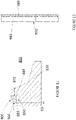
- seal piston assembly 800 comprises seal 860, seal energizer 880 and spacer 889, whereby spacer 889 is positioned in piston groove 890 next to seal energizer 880.
- Spacer 889 is made of a different material than energizer 880, preferably of a more compliant material, for example an elastomeric or a plastic material and it is dimensioned such that it fits tightly between seal energizer 880 and wall 870 of piston groove 890 to thereby position the seal energizer in a fixed axial position within the piston groove.
- Spacer 889 can be in the shape of a ring.
- FIG. 12 shows the view of a seal energizer 980 and a spring 989 positioned next to the seal energizer within piston groove 990.
- the seal of the piston is not illustrated, but a person skilled in the art would understand that the relative positioning of the seal, the spring and the seal energizer is similar with the one illustrated in Figure 11 . Due to the elastic properties of its material, spring 989 that is inserted in the piston groove between the seal energizer and the wall of the piston groove positions seal energizer 980 in a fixed axial position within piston groove 990.
- Figure 13 illustrates an embodiment of piston seal assembly 1000 comprising a seal energizer 1080 which supports a seal 1060 within piston groove 1090.
- seal 1060 comprises a portion 1061 which protrudes between seal energizer 1080 and wall 1070 of piston groove 1090. Because portion 1061 of the seal is made of a more elastic material than the seal energizer and because it is dimensioned to fit tightly between the seal energizer 1080 and wall 1070 of the piston groove it positions seal energizer 1080 in a fixed axial position within the piston groove.
- the seal which is part of the piston seal assembly is a seal in the shape of a split cut seal having two overlapping ends as illustrated in Figures 2 and 3 .
- FIGS. 1-10 are schematic representations of the disclosed reciprocating pump and piston seal assembly and are not drawn to scale. For example, some features such as for example the gaps G1, G2 and G3 between the lateral surfaces of the seal energizer and the piston groove walls may be enlarged relative to the other components to better illustrate their function and their relative dimensions. In addition, these schematic representations do not show all the physical details of the reciprocating pump and the piston seal assemblies.
Landscapes
- Engineering & Computer Science (AREA)
- General Engineering & Computer Science (AREA)
- Mechanical Engineering (AREA)
- Sealing Devices (AREA)
- Details Of Reciprocating Pumps (AREA)
- Compressor (AREA)
- Pistons, Piston Rings, And Cylinders (AREA)
Description
- The present disclosure relates to a reciprocating pump comprising a piston seal assembly with controlled leakage.
- Pistons which reciprocate within a cylinder bore are well known in the art and have been long used for pumps, hydraulic drives, engines, pneumatic drives and other hydraulic or pneumatic machines delivering different fluids at increased pressure. When the piston is moving within the cylinder, a piston seal assembly is employed for dynamic sealing to prevent fluid from leaking between the piston and the cylinder walls.
- Piston seals are subjected to substantive wear due to the piston's movement within the cylinder bore and sometimes they fail due to excessive wear and/or due to the stress caused by the pressure exerted on the seal by the fluid being compressed. Such operating conditions can be even more challenging in the case of high pressure reciprocating pumps and/or in the case of pumps handling cryogenic fluids.
- An example of such a reciprocating pump is a pump used to deliver a liquefied gaseous fuel from a cryogenic vessel to a gaseous-fuelled internal combustion engine. Such pumps can handle fluids at relatively high pressures, around 4600 psi, and at low temperatures, for example at around -130 degrees Celsius and lower. It is difficult to provide an effective seal for the piston of such a pump especially because the material of the seal has to withstand the low temperatures of the pumped fluid and the high compression stresses acting on the seal. Also, the different contraction coefficients of the materials from which the pump components and the seals are made can result in gaps being formed between the piston seals and the cylinder wall allowing fluid to leak from the compression chamber past the piston seal to the low pressure side of the pump.
- For all the reciprocating pumps in general, seal wear due to the reciprocating movement of the piston is a problem that needs to be addressed. In the past, split seals have been used to address the seal wear problem. Split seals have the shape of a ring having a cut which allows it to be installed on the piston and more importantly it allows the seal to expand to compensate for the seal wear. For maintaining the contact between the seal and the pump cylinder wall a seal energizer is provided for supporting the seal and pushing it towards the cylinder wall. The seal energizer can be a metal ring that is positioned underneath the seal and forms together with the seal a piston seal assembly that is placed in a piston groove. The seal energizer is split transversally such that there is a gap between the free ends of the ring which provides for an easier installation of the seal energizer in the piston groove and provides more elastic force for pushing the seal towards the cylinder wall when the seal assembly is installed in the piston groove.
- Generally there is a clearance gap between the seal energizer and the lateral walls of the piston groove where the seal assembly is positioned due to manufacturing tolerances. The dimensions of the gap can vary, but it can be in some cases larger than 0.15 mm. The size of the gap between the seal energizer and the piston groove can be controlled only through tight manufacturing tolerances and such gap represents a potential seal leak path which can affect the life span of the seal. With the known construction of seal energizers the seal leak path area can vary depending on the manufacturing tolerances of the seal energizer and of the piston groove and depending on the pump's operating conditions.
- Furthermore, if several seal assemblies, each comprising a seal and a seal energizer, are mounted in series for sealing the piston as it reciprocates within the pump cylinder, it has been observed that some seals show substantially more wear than others with at least one random seal failing after some time. This can be explained by the fact that the pressure drop across each seal varies. The pressure drop across each seal depends on the size of the leak path area through the seal, and seals with the smallest leak path area experience the greatest pressure drop due to the highest resistance to fluid pressure and will wear faster. The replacement of worn seals requires taking the apparatus out of service, removing the piston and replacing the seals.
-
US2785029 discloses a combined expander, side pressure spring and oil ventilator which may be used with a plain unvented compression ring in a lower oil groove of a piston for conserving and salvaging lubricating oil in engines. -
US2737429 describes a piston ring assembly. -
US1911735 discloses a piston ring. -
US2719767 describes a piston ring structure. -
US3477732 discloses a spacer-expander. - Accordingly, there is a desire to continually improve the life of the piston seals to increase the time between service intervals, improving seal wear consistency over time.
- The present invention provides a reciprocating pump as recited in claim 1.
-
-
Figure 1 is a schematic cross-sectional representation of a reciprocating pump having a piston comprising a series of piston seal assemblies; -
Figure 2 is a view of the piston illustrated inFigure 2 showing the series of S-cut seals; -
Figure 3 is a view of outer circumferential surface of a piston seal assembly illustrating the relative position between an S-cut seal and an underlying energizer within a piston groove and illustrating one of the possible leak paths through the seal assembly; -
Figures 4A, 4B and4C are schematic cross-sectional representations of a piston seal assembly located in a piston groove of a reciprocating pump, which illustrate the different axial positions of the seal energizer within the piston groove; -
Figure 5A is a view of a seal energizer according to a first embodiment andfigure 5B is a cross-sectional view of the piston seal assembly comprising the seal energizer illustrated infigure 5A , positioned in a piston groove; -
Figure 6A is a view of a seal energizer according to a second embodiment andfigure 6B is a cross-sectional view of the piston seal assembly comprising the seal energizer illustrated infigure 6A , positioned in a piston groove; -
Figure 7A and 7B show views of two embodiments of a seal energizer provided with tabs which are inserted in corresponding notches on the lateral surface of the seal energizer; -
Figure 8A is a view of a seal energizer according to a fourth embodiment of the present disclosure andfigures 8B and 8C illustrate two cross-sections through a piston seal assembly comprising the seal energizer illustrated infigure 8A , positioned in a piston groove; -
Figure 9A is a view of a seal energizer according to a fifth embodiment of the present disclosure andfigure 9B is a cross-sectional view of the piston seal assembly comprising the seal energizer illustrated infigure 9A , positioned in a piston groove; -
Figures 10A and 10B show views of two embodiments of a seal energizer made of two parts; -
Figure 11 shows a schematic cross-sectional representation of a piston seal assembly according to another embodiment of the present disclosure, comprising a spacer which is positioned next to the seal energizer within the piston groove; -
Figure 12 shows a view of another embodiment of the present disclosure which comprises a seal energizer and a spring positioned next to the seal energizer within a piston groove; and -
Figure 13 shows a schematic cross-sectional representation of a piston seal assembly according to another embodiment of the present disclosure, comprising a seal that has a portion which protrudes between seal energizer and a wall of the piston groove where the seal assembly is located. - The disclosed apparatus was developed for piston seals for reciprocating cryogenic piston pumps which have some particular characteristics which require improved design features. The improved seal assembly is described herein in the context of this application. Nevertheless the teachings of the disclosed apparatus can be applied to improve seal life for many different applications for reciprocating pumps comprising piston seal assemblies that employ a piston ring seal and seal energizer.
-
Figure 1 illustrates areciprocating pump 110, known in the prior art, which comprises acylinder bore 120, defined by the body of the pump, and apiston 130 which is actuated by an actuating mechanism (not illustrated) through ashaft 133 such that it has a reciprocating movement D withincylinder bore 120. Whenpiston 130 moves in one direction it draws in fluid intocompression chamber 150 through the pump's intake port, during the intake stroke, and whenpiston 130 moves in the opposite direction, it compresses the fluid withincompression chamber 150 during the compression stroke of the pump. - Piston 130 comprises a series of
seal assemblies Figures 3 ,4A ,4B and4C . Each seal can have a split configuration as illustratedFigure 2 and further detailed inFigure 3 . The type of seal energizer illustrated inFigures 1 and3 is known in the prior art and is generally provided for seal assemblies comprising a split seal, more commonly known as an "S-cut" seal, to allow the seal to remain in close proximity to the cylinder wall when the outer circumferential surface is worn, thereby maintaining a good seal between the piston and the cylinder wall. Eachsplit seal Figure 3 illustrates a view of the outer circumferential surface ofseal assembly 100A which comprisesseal 160A andunderlying seal energizer 180A. Seal 160A has two overlapping end segments, afirst end segment 112A and asecond end segment 114A, each having a width that is smaller than the width of the main body of the seal. Seal 160A is supported byseal energizer 180A and the seal assembly formed by the seal and the seal energizer is located in acircumferential piston groove 190A, formed in the piston, as better illustrated inFigures 4A, 4B and4C . - For reciprocating pumps that comprise a piston which reciprocates within a cylinder and has at least one least seal assembly comprising a seal energizer and a seal which seals the interface between the piston and the cylinder wall, it has been found that the axial position of the seal energizer within the piston groove determines the size of the leakage area through the seal which affects the pressure drop across the seal. As illustrated in
Figure 4A , which shows a pistonassembly comprising seal 160A andseal energizer 180A positioned inpiston groove 190A, ifseal energizer 180A is positioned closer to thegroove wall 140A that is closer to the higher pressure side of the piston, which is the side closer to thecompression chamber 150, the leak path between the seal energizer and thegroove wall 170A, which is closer to the low pressure side of the piston, allows a bigger gap G1 and implicitly a larger leak area compared to leak path through the seal assembly whenseal energizer 180A is positioned axially in the centre ofgroove 190A, as illustrated inFigure 4B where gap G2 is smaller than G1, or ifseal energizer 180A is positioned closer togroove wall 170A, as illustrated inFigure 4C where gap G3 is the smallest. It was found that in order to have a consistent wear of the seal over time, or to have a consistent wear spread across a series of seals it is preferred to control the positioning of the seal energizer in the piston groove. Preferably the seal energizer is consistently positioned in the piston groove such that one of its lateral surfaces is in contact with the piston groove wall that is closer to the lower pressure side of the piston which allows the smallest leak path area for any fluid leaking from the high pressure side of the piston, as illustrated inFigure 4C . - A first embodiment of the present seal energizer and seal assembly is illustrated in
Figures 5A and 5B .Seal energizer 280 is in the shape of a split ring comprising an outercircumferential surface 281, an innercircumferential surface 282, a firstlateral surface 283 and a secondlateral surface 284, adjoining the outer and inner circumferential surfaces and it comprises agap 285 between the free ends of the split ring.Piston seal assembly 200 comprisesseal 260 andseal energizer 280 whose outercircumferential surface 281 supportsseal 260. Piston seal assembly is installed inpiston groove 290 ofpiston 230.Seal 260 is generally a split seal and more particularly an S-cut seal as shown inFigures 2 and3 . In this first embodiment, firstlateral surface 283 ofseal energizer 280 is provided with a plurality oftabs 286 extending in a direction perpendicular to the first lateral surface and positioned at predetermined spaced intervals along the first lateral surface ofseal energizer 280.Figure 5A illustrates a seal energizer with fourtabs 286 spaced evenly along firstlateral surface 283 of the seal energizer. A person skilled in the art would understand that the seal energizer can be provided with any number of tabs, including just one tab. In preferred embodiments there are at least three tabs equally spaced along the first lateral surface of the seal energizer so that the tabs ensure a stable axial position of the seal energizer within the piston groove as illustrated inFigure 5B and as further explained below. -
Seal energizer 280 is placed inpiston groove 290 with its firstlateral surface 283 which is provided withtabs 286 facinggroove wall 270 that is closer tocompression chamber 250 which is the higher pressure side ofpiston 230; and facing away fromgroove wall 240 that is closer to the lower side of the piston. Becauseonly tabs 286 come in contact withwall 270 of the piston groove the manufacturing tolerance requirements for the first lateral surface of the seal energizer are less strict and only the surfaces of the tabs that are facing the groove wall need to be manufactured within tight tolerances to ensure a fixed axial position of the energizer within the piston groove. The axial positioning of the seal energizer within the piston groove illustrated inFigure 5B achieves a similar result with the one illustrated inFigure 4C , such that this arrangement ensures a reduced leak path area, corresponding to gap G3. The majority of the fluid leaking from the compression chamber on the high pressure side ofpiston 230 escapes by flowing into the bottom of the piston groove underneathseal energizer 280 and is substantially blocked from passing the seal assembly towards the low pressure side of the piston. The height and width oftabs 286 are dimensioned to control the leakage through the piston seal assembly and to ensure a stable positioning of the seal energizer in a fixed position within the piston groove.Tabs 286 are illustrated having a rectangular shape, but they can have a rounded or semicircular shape or any other shape that allows an appropriate contact surface with the wall of the piston groove where the seal energizer is positioned. - A second embodiment of the seal energizer and of the seal assembly is illustrated in
Figures 6A and 6B .Seal energizer 380 has the shape of split ring comprising an outercircumferential surface 381, an innercircumferential surface 382, a firstlateral surface 383 and a secondlateral surface 384, adjoining the outer and inner circumferential surfaces and it comprises agap 385 between the free ends of the split ring.Piston seal assembly 300 comprises aseal 360 andseal energizer 380 whose outercircumferential surface 381 supports the seal, and is installed inpiston groove 390 ofpiston 330.Seal 360 is generally a split seal or an S-cut seal that can have the shape illustrated inFigures 2 and3 . In this second embodiment, firstlateral surface 383 ofseal energizer 380 is provided with a plurality oftabs 386 extending in a direction perpendicular to the firstlateral surface 383 and a plurality oftabs 387 extending in a direction perpendicular to thelateral surface 384.Figure 6A illustrates a seal energizer with fourtabs 386 spread evenly along firstlateral surface 383 of the seal energizer and with fourtabs 387, with eachtab 387 having its axis aligned with the axis of itscorresponding tab 386, such that they substantially share acommon axis 388. A person skilled in the art would understand that the seal energizer can be provided with any number of tabs, including only one tab on each of the lateral surfaces of the seal energizer and that preferably it comprises at least threetabs 386 equally spaced along the first lateral surface of the seal energizer and at least threecorresponding tabs 387 spaced along the second lateral surface of the seal energizer. The tabs on one lateral surface of the seal energizer don't have to be aligned with the tabs on the other lateral surface of the seal energizer as long as they are distributed to ensure a stable position of the seal energizer within the piston groove. - As illustrated in
Figure 6B ,seal energizer 380 is placed inpiston groove 390 with firstlateral surface 383 provided withtabs 386 facinggroove wall 370 that is closer tocompression chamber 350 and with secondlateral surface 384 provided withtabs 387 facinggroove wall 340 that is closer to the lower side of the piston. In the illustrated embodiment, since the tabs are evenly distributed on both lateral surfaces of the seal energizer and because they have equal dimensions there is no particular preference in regards to which lateral surface is facing each side ofpiston 330. In other embodiments,tabs 387 can have a different width and depth thantabs 386 and preferablytabs 387 on the lateral surface of the seal energizer that is closer to the lower pressure side of the piston have a smaller height than the tabs on the other lateral surface of the seal energizer to minimize the leak path area through gap G2. Becauseonly tabs wall 370 and respectively wall 340 of the piston groove, the manufacturing tolerance requirements for the lateral surfaces of the seal energizer are less strict and only the surfaces of the tabs that are facing the groove wall need to be manufactured within tight tolerances. Especiallytabs 387 whichcontact wall 340 closer to the lower pressure side of the pump have to have a tightly controlled height because their height controls the size of gap G2. The axial positioning of the seal energizer within the piston groove illustrated inFigure 6B is similar with the one illustrated inFigure 4B . The leak path area corresponding to gap G2 in this second embodiment is slightly larger than the leak path area corresponding to gap G1 illustrated inFigure 5B , but this second embodiment can enable an easier installation and assembly process of the seal assembly, while maintaining a controlled leak through the seal assembly.Tabs -
Figure 7A illustrates a third embodiment of the seal energizer.Seal energizer 480A has a similar construction with the seal energizer of the first embodiment illustrated inFigure 5A . It has the shape of split ring comprising an outercircumferential surface 481A, an innercircumferential surface 482A, a firstlateral surface 483A and a secondlateral surface 484A, adjoining the outer and inner circumferential surfaces and it comprises agap 485A between the free ends of the split ring. Firstlateral surface 483A ofseal energizer 480A is provided with a plurality oftabs 486A extending in a direction perpendicular to the first lateral surface and positioned at predetermined spaced intervals along the first lateral surface of the seal energizer.Figure 7 illustrates a seal energizer with seventabs 486A spread evenly along firstlateral surface 483A of the seal energizer. A person skilled in the art would understand that the seal energizer can be provided with any number of tabs and that preferably it comprises at least three tabs equally spaced along the first lateral surface of the seal energizer so that the tabs ensure a stable axial position of the seal energizer within the piston groove. In this embodiment,tabs 486A which extend fromsurface 483A of the seal energizer are preferably made from a compliant material which has a low thermal expansion coefficient. The tabs are fitted intonotches 451A provided in the firstlateral surface 483A of the seal energizer and are illustrated as having a semicircular surface. The tabs can be injection molded into the notches provided in the seal energizer or they can be manufactured separately by any method known in the art and then inserted into the corresponding notches provided in the seal energizer. The tabs can be made of the same material as the seal energizer or of a softer, more elastic material than the material of the seal energizer, for example an elastomeric or a plastic material. A person skilled in the art would understand thattabs 486A can have a rectangular shape, similar with the tabs illustrated inFigure 5A , or any other shape that allows an appropriate contact surface with the wall of the piston groove where the seal energizer is positioned. -
Seal energizer 480A is placed in a piston groove in a similar way as theseal energizer 280 of the first embodiment, as illustrated inFigure 5B . When the seal energizer is positioned within the piston groove, firstlateral surface 483A provided withtabs 486A faces the groove wall that is closer to the higher pressure side of the pump piston. Becausetabs 486A are made of a compliant material there is no requirement regarding tight manufacturing tolerances of the tabs. When the seal energizer is positioned within the piston groove the tabs are pressed against the wall of the groove thereby positioning the seal energizer in a fixed axial position within the groove. The axial positioning of the seal energizer within the piston groove is similar with the one illustrated inFigure 5B and such arrangement ensures a reduced leak path area through the piston seal assembly. - In the embodiment illustrated in
Figure 7B lateral surface 483B ofseal energizer 480B is provided withnotches 451B andseal energizer 480B comprises acomponent 489B which is provided withtabs 486B, fitted in these notches, and with connectingportions 441B between these tabs. It has the shape of a split ring comprising an outercircumferential surface 481B, an innercircumferential surface 482B, a firstlateral surface 483B and a secondlateral surface 484B, adjoining the outer and inner circumferential surfaces and it comprises agap 485B between the free ends of the split ring.Component 489B can be manufactured separately by any method known in the art, and then fitted on thelateral surface 483B of the seal energizer withtabs 486B inserted innotches 451B.Component 489B can be made of the same material as the seal energizer or of softer, more elastic material than the material of the seal energizer, for example an elastomeric or plastic material. - The fourth embodiment of the seal energizer is illustrated in
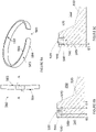
Figure 8A .Seal energizer 580 has the shape of split ring comprising an outercircumferential surface 581, an innercircumferential surface 582, a firstlateral surface 583 and a secondlateral surface 584, adjoining the outer and inner circumferential surfaces and it comprises agap 585 between the free ends of the split ring. In this embodiment the first and second lateral surfaces of the seal energizer are curved the curvature of these two surfaces being defined by an angle α and respectively β. Angles α and β are the angles defined by the respective lateral surface of the seal energizer and a straight planar surface perpendicular on the axis A-A of the seal energizer. In the embodiment illustrated inFigure 8A the two curvatures of the firstlateral surface 583 and respectively of the secondlateral surface 584 are equal (α=β). In other embodiments the two curvatures can be different and should be calculated such that the seal energizer is kept in the fixed position within the piston groove. - Like in the other embodiments, in this fourth embodiment
piston seal assembly 500 comprisesseal 560 andseal energizer 580 whose outercircumferential surface 581 supports the seal and is installed inpiston groove 590 ofpiston 530.Seal 560 is generally a split seal that can have an S-cut as illustrated inFigures 2 and3 .Seal energizer 580 is preferably positioned withinpiston groove 590 such that in the area of the S-cut, more specifically in the area where the free ends of the seal are overlapping, secondlateral surface 584 comes into contact withgroove wall 540, as illustrated inFigure 8B . The axial positioning of the seal energizer within the piston groove, illustrated inFigure 8B , achieves a similar result with the one illustrated inFigure 4C , and this arrangement ensures that the leak path area, corresponding to gap G3, is smaller than that of gap G4 which is the gap between firstlateral surface 583 of the seal energizer andgroove wall 570 that is closer to thehigh pressure side 550 of the piston due to the curvature of the lateral surfaces of the seal energizer. The majority of the fluid leaking from the high pressure side ofpiston 530 byseal 560 and reaching the bottom of piston groove underneathseal energizer 580 will be substantially blocked from passing the seal assembly towards the lower pressure side of the piston, opposite tocompression chamber 550. -
Figure 8C illustrates the position of the seal energizer in a cross-section through the piston seal assembly along a plane that is positioned at a 90 degree angle relative to the cross-sectional view illustrated inFigure 8B . As seen here, firstlateral surface 583 comes into contact withgroove wall 570 that is closer to thehigh pressure side 550 of the piston. In this section of the piston seal assembly, the leak path between the seal energizer and thegroove wall 540 that is closer to the low pressure side of the piston allows a bigger gap G1 and implicitly a larger leak area, but this portion of the seal energizer is not positioned underneath the area where the free ends of the seal are overlapping and where the potential of fluid leaking past the seal assembly is higher. - In this embodiment it is preferred to have a fixed relative position between
seal energizer 580 and seal 560 such that the reduced leak area through the piston seal assembly corresponds to the area where the free ends of the seal are overlapping. - A fifth embodiment of the seal energizer and of the seal assembly is illustrated in
Figures 9A and 9B .Seal energizer 680 has the shape of split ring comprising an outercircumferential surface 681, an innercircumferential surface 682, a firstlateral surface 683 and a secondlateral surface 684, adjoining the outer and inner circumferential surfaces and it comprises agap 685 between the free ends of the split ring.Piston seal assembly 600 comprisesseal 660 andseal energizer 680 whose outercircumferential surface 681 supports the seal and is installed inpiston groove 690 ofpiston 630.Seal 660 is generally a split seal or an S-cut seal that can have the shape illustrated inFigures 2 and3 . In this first embodiment, firstlateral surface 683 ofseal energizer 680 is provided with a plurality ofrecesses 686 positioned at predetermined intervals along the first lateral surface of the seal energizer.Figure 9A illustrates a seal energizer with fourrecesses 686 spread evenly along firstlateral surface 683 of the seal energizer. A person skilled in the art would understand that the seal energizer can be provided with a different number of recesses, with at least one recess being provided on one of the lateral surfaces of the seal energizer. The recesses illustrated inFigure 9A have a semicircular shape, but a person skilled in the art would recognize that the recesses provided on the surface of the seal energizer can be of any other shapes. -
Seal energizer 680 is placed inpiston groove 690 with firstlateral surface 683 provided withrecesses 686 facinggroove wall 670 that is closer tocompression chamber 650. In this embodiment, the manufacturing tolerance requirements for the first and second lateral surfaces of the seal energizer are stricter to ensure a fixed axial position of the energizer within the piston groove. Also, the depth of the recesses on the lateral surface of the seal energizer closer to the higher pressure side of the piston has to be controlled through manufacturing tolerances to be more precise such that it allows a better control of the leak area through the piston seal assembly. The axial positioning of the seal energizer within the piston groove illustrated inFigure 9B achieves a similar result with the one illustrated inFigure 4C , ensuring a reduced leak path area, corresponding to gap G3. The majority of the fluid leaking from the high pressure side ofpiston 630, passing along the first lateral surface ofseal 660 throughrecesses 686 and reaching the bottom of piston groove underneathseal energizer 680 will be substantially blocked from passing the seal assembly towards the lower side of the piston. -
Figures 10A and 10B show the views of another embodiments of a seal energizer disclosed here.Seal energizer 780A made of twoparts First part 711A has an outercircumferential surface 771A and an innercircumferential surface 775A andsecond part 713A has an outercircumferential surface 773A and an innercircumferential surface 777A which form together the outer circumferential surface of the seal energizer withgap 785A which supports the seal of the piston seal assembly and respectively the inner circumferential surface of the seal energizer which faces the piston groove wall when seal energizer 780A is placed in the piston groove.Part 713A has a lateral surface which is the firstlateral surface 783A of the seal energizer and it is shaped to position the seal energizer in a fixed axial position within the piston groove. InFigure 10A firstlateral surface 783A is provided withseveral tabs 786A which extend in a direction perpendicular to the first lateral surface such that when seal energizer 780A is placed in apiston groove tabs 786A are in contact with a wall of the piston groove to position the seal energizer in a fixed axial position within the piston groove in a similar manner as illustrated inFigure 5B and explained in more detail in relation to the first embodiment of the present disclosure. - A person skilled in this technology would understand that
seal energizer 780A can have a shape similar to the one illustrated inFigure 6A where both the firstlateral surface 783A and the secondlateral surface 784A can be provided with tabs and that in thisvariant seal energizer 780A could be made, for example, of two or three parts having a common longitudinal axis when positioned next to each other in the piston groove. - In another embodiment illustrated in
Figure 10B seal energizer 780B is made of twoparts Figure 10A have like reference numerals and may not be described in detail if at all. In the present embodiment,part 713B is made of a more compliant material than the material ofpart 711B, for example an elastomeric or plastic material, and it is dimensioned to positionseal energizer 780B in a fixed axial position within the piston groove. Sincesecond part 713B is made of a more compliant material, the tolerances for firstlateral surface 783B of the seal energizer are less strict and, at the same time,second part 713B is dimensioned such thatseal energizer 780B fits tightly within the piston groove and thereby positions the seal energizer in a fixed axial position within the piston groove. - Another embodiment of the present piston seal assembly is illustrated in
Figure 11 . In this embodimentseal piston assembly 800 comprisesseal 860,seal energizer 880 andspacer 889, wherebyspacer 889 is positioned inpiston groove 890 next to sealenergizer 880.Spacer 889 is made of a different material thanenergizer 880, preferably of a more compliant material, for example an elastomeric or a plastic material and it is dimensioned such that it fits tightly betweenseal energizer 880 andwall 870 ofpiston groove 890 to thereby position the seal energizer in a fixed axial position within the piston groove.Spacer 889 can be in the shape of a ring. - Yet another embodiment of the present piston seal assembly can comprise a spring instead of the spacer illustrated in
Figure 11 . This embodiment is illustrated inFigure 12 which shows the view of aseal energizer 980 and aspring 989 positioned next to the seal energizer withinpiston groove 990. In this view, the seal of the piston is not illustrated, but a person skilled in the art would understand that the relative positioning of the seal, the spring and the seal energizer is similar with the one illustrated inFigure 11 . Due to the elastic properties of its material,spring 989 that is inserted in the piston groove between the seal energizer and the wall of the piston groove positions sealenergizer 980 in a fixed axial position withinpiston groove 990. -
Figure 13 illustrates an embodiment ofpiston seal assembly 1000 comprising aseal energizer 1080 which supports aseal 1060 withinpiston groove 1090. In thisembodiment seal 1060 comprises aportion 1061 which protrudes betweenseal energizer 1080 andwall 1070 ofpiston groove 1090. Becauseportion 1061 of the seal is made of a more elastic material than the seal energizer and because it is dimensioned to fit tightly between theseal energizer 1080 andwall 1070 of the piston groove it positionsseal energizer 1080 in a fixed axial position within the piston groove. - The embodiments illustrated in
Figures 12 and13 allow a similar positioning of the seal energizer as the embodiment illustrated inFigure 5B , ensuring a reduced leak path area, corresponding to gap G3. - In the illustrated embodiments the seal which is part of the piston seal assembly is a seal in the shape of a split cut seal having two overlapping ends as illustrated in
Figures 2 and3 . - The figures in the present disclosure are schematic representations of the disclosed reciprocating pump and piston seal assembly and are not drawn to scale. For example, some features such as for example the gaps G1, G2 and G3 between the lateral surfaces of the seal energizer and the piston groove walls may be enlarged relative to the other components to better illustrate their function and their relative dimensions. In addition, these schematic representations do not show all the physical details of the reciprocating pump and the piston seal assemblies.
- In the figures of the present disclosure like components between different embodiments have like reference numerals and may have not been described in detail, if at all.
- The present invention has been described with regard to a plurality of illustrative embodiments. However, it will be apparent to persons skilled in the art that a number of variations and modifications can be made without departing from the scope of the invention as defined in the claims.
Claims (15)
- A reciprocating pump (110) comprising:a cylinder bore (120);a piston (130, 230, 330, 530, 630, 830, 1030) which is actuated by an actuating mechanism through a shaft (133) such that the piston has a reciprocating movement within the cylinder bore (120), wherein the piston (130, 230, 330, 530, 630, 830, 1030) comprises a circumferential piston groove (290, 390, 590, 690, 890, 1090);a compression chamber (150) defined in said cylinder bore; anda piston seal assembly (200, 300, 500, 600, 800, 1000) for dynamic sealing between the piston (230, 330, 530, 630, 830, 1030) and the cylinder bore (120), said piston seal assembly being disposed in the circumferential piston groove (290, 390, 590, 690, 890, 1090) and comprising a seal (260, 360, 560, 660, 860, 1060) and a radial seal energizer (280, 380, 480A, 480B, 580, 680, 780A, 780B, 880, 1080) for supporting said seal in said circumferential piston groove (290, 390, 590, 690, 890, 1090), said radial seal energizer has a shape of a split ring (285, 385, 485A, 485B, 585, 685, 785A) comprising an outer circumferential surface (281, 381, 481A, 481B, 581, 681, 771A/773A, 771B/773B) and an inner circumferential surface (282, 382, 482A, 482B, 582, 682, 775A/777A, 775B/777B), a first lateral surface (283, 383, 483A, 489B, 583, 683, 783A, 783B) and a second lateral surface (284, 384, 484A, 484B, 584, 684, 784A, 784B) thereby adjoining said outer and inner circumferential surfaces wherein said outer circumferential surface of said radial seal energizer is adapted to provide substantially radial support to said seal, wherein the radial seal energizer is split transversally such that there is a gap between free ends of the split ring and characterized in that said first lateral surface and said second lateral surface are shaped to position said radial seal energizer in a fixed axial position within said circumferential piston groove when said reciprocating pump is in operation and to provide a controlled leak path (G2, G3, G4) through the seal assembly between the radial seal energizer and piston groove,wherein the radial seal energizer (280, 380, 480A, 480B, 780A) is positioned in the piston groove (290, 390) such that its second lateral surface (284, 384, 484A, 484B, 784A) is in contact with a wall of the piston groove (240, 340, 540, 1040) which is furthest away from the compression chamber (150) side of the piston and the first lateral surface faces towards a wall of the piston groove (270, 370, 570, 670) which is closest to the compression chamber (150) side of the piston and such that a first leak path (G2, G3) is defined between said second lateral surface (284, 384, 484A, 484B, 784A) and the wall of the piston groove (240, 340, 540, 1040) which is furthest away from the compression chamber (150) side of the piston, a second leak path is defined between said first lateral surface (283, 383, 483A, 489B, 583, 683, 783A, 783B) and the wall of the piston groove (270, 370, 570, 670) which is closest to the compression chamber (150) side of the piston, wherein the first leak path is smaller than the second leak path such that the first leak path provides the smallest leak path (G2, G3) area for fluid leaking from the compression chamber (250, 350, 550, 650 850, 1050) such that at least some of the fluid leaking from the compression chamber reaching a bottom of the piston groove underneath said radial seal energizer is blocked from passing through said seal assembly and said piston groove.
- The reciprocating pump of claim 1, wherein said first lateral surface (283, 383, 483A, 483B, 783A) of said seal energizer is provided with at least one tab (286, 386, 486A, 486B, 786A) extending in a direction perpendicular to said first lateral surface that is closer to said compression chamber (250) of said pump.
- The reciprocating pump of claim 1, wherein said first lateral surface of said seal energizer is provided with a plurality of tabs (286, 386, 486A, 486B, 786A) extending in a direction perpendicular to said first lateral surface, said tabs being positioned at predetermined spaced intervals on said first lateral surface.
- The reciprocating pump of claim 1 or 2, wherein said second lateral surface (384) of said radial seal energizer is also provided with at least one tab (387) extending in a direction perpendicular to said second lateral surface.
- The reciprocating pump of claim 3, wherein said second lateral surface (384) of said seal energizer is also provided with a plurality of tabs (387) extending in a direction perpendicular to said second lateral surface, said plurality of tabs being positioned at predetermined spaced intervals on said second lateral surface and said plurality of tabs (387) extending in a direction perpendicular to said second lateral surface has a smaller height than the plurality of tabs (386) extending in a direction perpendicular to said first lateral surface.
- The reciprocating pump of claim 5, wherein there is an equal number of said tabs associated with said first lateral surface and said second lateral surface, wherein an axis of each of said tabs extending from said first lateral surface (383) in a direction perpendicular to a circumferential direction of said radial seal energizer (380) is aligned with an axis (388) of a corresponding tab (387) from said tabs on said second lateral surface (384).
- The reciprocating pump of any of claims 3, 5 or 6, wherein said tabs are separate from said first or second surface of said seal energizer and are inserted into corresponding notches located on said first and/or second lateral surface of said seal energizer.
- The reciprocating pump of claim 1, wherein the radial seal energizer (480B, 780A) is made of at least two parts (484B/489B; 713A/711A, 713B/711B) with a first part (484B, 711A, 711B) disposed closer to the lower pressure side of the piston and a second part (489B, 713A, 713B) disposed closer to the compression chamber (250) of said pump; each part having an outer circumferential surface which together form said outer circumferential surface (481B, 771A/773A, 771B/773B) of the seal energizer (485B, 780A, 780B) which supports the seal of the piston seal assembly and each part having an inner circumferential surface which together form said inner circumferential surface (482B, 775A/777A, 775B/777B) of the seal energizer which faces an inner most piston groove wall.
- The reciprocating pump of claim 1, wherein said first lateral surface of said seal energizer is provided with at least one recess (686), and wherein said first lateral surface (683) of said seal energizer (680) is provided with a plurality of recesses (686) positioned at predetermined spaced intervals on said first lateral surface (683).
- The reciprocating pump of claim 1, wherein said seal comprises a portion (1061) which protrudes between said seal energizer (1080) and a wall (1070) of said circumferential piston groove (1090) and wherein said portion (1061) of said seal is dimensioned to position said seal energizer (1080) in a fixed axial position within said circumferential piston groove (1090).
- The reciprocating pump of claim 1, wherein said first lateral surface and said second lateral surface of said seal energizer (580) are curved to position said radial seal energizer in a fixed axial position within said circumferential piston groove (590) and the curvature of said first lateral surface and said second lateral surface are defined by an angle α and respectively β and wherein angles α and β are angles defined by the respective lateral surface of the seal energizer and a straight planar surface perpendicular on the axis A-A of the seal energizer.
- The reciprocating pump of claim 1, further comprising a spacer (889, 989) positioned within said circumferential piston groove between said seal energizer (880, 980) and a wall (870) of said circumferential piston groove closer to said compression chamber (850), said spacer being designed to position said seal energizer in the fixed axial position within said circumferential piston groove.
- The reciprocating pump of claim 12 wherein said spacer is a spring (989).
- The reciprocating pump of any preceding claim, wherein said reciprocating pump compresses cryogenic fluids at pressures higher than 20.68 MPa (3000 psi).
- The reciprocating pump of any preceding claim, wherein said reciprocating pump compresses cryogenic fluid.
Applications Claiming Priority (2)
| Application Number | Priority Date | Filing Date | Title |
|---|---|---|---|
| CA2847760A CA2847760C (en) | 2014-03-28 | 2014-03-28 | Piston seal assembly with controlled leakage |
| PCT/CA2015/050231 WO2015143559A1 (en) | 2014-03-28 | 2015-03-25 | Piston seal assembly with controlled leakage |
Publications (3)
| Publication Number | Publication Date |
|---|---|
| EP3134665A1 EP3134665A1 (en) | 2017-03-01 |
| EP3134665A4 EP3134665A4 (en) | 2018-03-21 |
| EP3134665B1 true EP3134665B1 (en) | 2022-09-14 |
Family
ID=50929184
Family Applications (1)
| Application Number | Title | Priority Date | Filing Date |
|---|---|---|---|
| EP15769025.6A Active EP3134665B1 (en) | 2014-03-28 | 2015-03-25 | Piston seal assembly with controlled leakage |
Country Status (5)
| Country | Link |
|---|---|
| US (1) | US10316837B2 (en) |
| EP (1) | EP3134665B1 (en) |
| CN (1) | CN106461079B (en) |
| CA (1) | CA2847760C (en) |
| WO (1) | WO2015143559A1 (en) |
Families Citing this family (11)
| Publication number | Priority date | Publication date | Assignee | Title |
|---|---|---|---|---|
| CN107100880B (en) * | 2017-07-04 | 2020-06-26 | 湖南机油泵股份有限公司 | Flow guide ring for engine cooling water pump |
| CN107100884B (en) * | 2017-07-04 | 2020-01-10 | 湖南机油泵股份有限公司 | Engine cooling water pump capable of preventing coolant from being mixed into lubricating oil |
| CN109253184B (en) * | 2017-07-12 | 2022-05-03 | 舍弗勒技术股份两合公司 | Piston, clutch release system master cylinder, and method for manufacturing piston body |
| RU2669723C1 (en) * | 2018-01-10 | 2018-10-15 | Пётр Олегович Александров | Oil well pump |
| JP7002401B2 (en) * | 2018-04-27 | 2022-02-10 | 株式会社神戸製鋼所 | Compressor |
| CN110030429A (en) * | 2019-05-07 | 2019-07-19 | 浙江欧菲石油设备有限公司 | A kind of flexible sealing valve and its retaining ring |
| US20210033195A1 (en) * | 2019-07-31 | 2021-02-04 | Roller Bearing Company Of America, Inc. | Multiple piece seal ring assembly |
| IT201900014709A1 (en) | 2019-08-13 | 2021-02-13 | Faiveley Transport Italia Spa | Piston for reciprocating compressor with complementary sealing elements |
| KR102441415B1 (en) * | 2020-06-03 | 2022-09-07 | 현대중공업 주식회사 | Gas supply pump for ship dual fuel engine |
| CN115698505A (en) | 2020-06-03 | 2023-02-03 | 现代重工业株式会社 | Gas supply pump for dual-fuel engine of ship |
| EP4008933A1 (en) * | 2020-12-04 | 2022-06-08 | Burckhardt Compression AG | Piston ring for a piston compressor |
Citations (4)
| Publication number | Priority date | Publication date | Assignee | Title |
|---|---|---|---|---|
| US1911735A (en) * | 1933-05-30 | Piston ring | ||
| US2719767A (en) * | 1952-04-12 | 1955-10-04 | Guy H Hall | Piston ring structure |
| US2737429A (en) * | 1953-06-05 | 1956-03-06 | Perfect Circle Corp | Piston ring assembly |
| US3477732A (en) * | 1965-04-14 | 1969-11-11 | Sealed Power Corp | Spacer-expander |
Family Cites Families (19)
| Publication number | Priority date | Publication date | Assignee | Title |
|---|---|---|---|---|
| US2785029A (en) * | 1954-08-23 | 1957-03-12 | Sealed Power Corp | Combination piston ring expander, side pressure spring and oil ventilator |
| US2917353A (en) * | 1957-04-18 | 1959-12-15 | Goetzewerke | Tensioning spring for piston rings |
| US3000678A (en) * | 1959-11-24 | 1961-09-19 | Wilkening Mfg Co | Piston ring |
| DE1239149B (en) * | 1964-10-06 | 1967-04-20 | Goetzewerke | Tension spring for piston rings |
| CA975019A (en) | 1973-09-28 | 1975-09-23 | Peter F. Seylar | Dual composition sealing ring with rectangular cross section and method of making same |
| GB8504008D0 (en) | 1985-02-16 | 1985-03-20 | Ae Plc | Piston & ring |
| GB8813784D0 (en) | 1988-06-10 | 1988-07-13 | Dowty Seals Ltd | Seals |
| CN2055883U (en) | 1989-07-18 | 1990-04-11 | 吕复兴 | Overlapped piston-ring sealing device |
| GB2239925A (en) | 1990-01-11 | 1991-07-17 | Dowty Seals Ltd | Seals |
| CN1205393A (en) | 1997-07-12 | 1999-01-20 | 姜牧 | Combined long service, high air tight piston ring and I. C. engine made therefrom |
| JPH1163225A (en) | 1997-08-08 | 1999-03-05 | Yamaha Motor Co Ltd | piston ring |
| CN2340919Y (en) | 1998-09-24 | 1999-09-29 | 袁大学 | Fully sealed piston ring |
| US20020145259A1 (en) | 2001-04-04 | 2002-10-10 | Chalk David Jonathan | Directional, low-leakage seal assembly |
| CN1479028A (en) | 2003-03-04 | 2004-03-03 | 平 王 | Composite type flexible sealing piston ring |
| CN2692363Y (en) | 2004-04-23 | 2005-04-13 | 张坤 | Piston ring |
| CN201475308U (en) | 2009-09-01 | 2010-05-19 | 复盛实业(上海)有限公司 | Piston ring |
| CN101813034A (en) | 2010-04-01 | 2010-08-25 | 奇瑞汽车股份有限公司 | Piston ring for optical controlled engine |
| CN102367868A (en) | 2011-10-26 | 2012-03-07 | 太仓市明宇密封件有限公司 | Combined seal ring for CST hole |
| CN202719131U (en) | 2012-05-18 | 2013-02-06 | 中山市亚泰机械实业有限公司 | A piston elastic sealing ring and piston mechanism |
-
2014
- 2014-03-28 CA CA2847760A patent/CA2847760C/en active Active
-
2015
- 2015-03-25 EP EP15769025.6A patent/EP3134665B1/en active Active
- 2015-03-25 US US15/300,249 patent/US10316837B2/en active Active
- 2015-03-25 WO PCT/CA2015/050231 patent/WO2015143559A1/en not_active Ceased
- 2015-03-25 CN CN201580027811.3A patent/CN106461079B/en active Active
Patent Citations (4)
| Publication number | Priority date | Publication date | Assignee | Title |
|---|---|---|---|---|
| US1911735A (en) * | 1933-05-30 | Piston ring | ||
| US2719767A (en) * | 1952-04-12 | 1955-10-04 | Guy H Hall | Piston ring structure |
| US2737429A (en) * | 1953-06-05 | 1956-03-06 | Perfect Circle Corp | Piston ring assembly |
| US3477732A (en) * | 1965-04-14 | 1969-11-11 | Sealed Power Corp | Spacer-expander |
Also Published As
| Publication number | Publication date |
|---|---|
| CA2847760A1 (en) | 2014-06-11 |
| CA2847760C (en) | 2016-10-11 |
| EP3134665A4 (en) | 2018-03-21 |
| EP3134665A1 (en) | 2017-03-01 |
| US20170146010A1 (en) | 2017-05-25 |
| US10316837B2 (en) | 2019-06-11 |
| CN106461079B (en) | 2019-10-18 |
| WO2015143559A1 (en) | 2015-10-01 |
| CN106461079A (en) | 2017-02-22 |
Similar Documents
| Publication | Publication Date | Title |
|---|---|---|
| CA2847760C (en) | Piston seal assembly with controlled leakage | |
| US8757047B2 (en) | Low leakage plunger assembly for a high pressure fluid system | |
| EP2971879B1 (en) | High pressure lip seals with anti-extrusion and anti-galling properties and related methods | |
| EP3665405B1 (en) | Piston sealing ring assembly having a gap cover element | |
| JP7542112B2 (en) | Piston ring set | |
| US10851893B2 (en) | Piston arrangement | |
| EP3126718B1 (en) | Piston seal | |
| AU2020213671A1 (en) | Packaging ring with wear opening | |
| CN110925113A (en) | Oil scraper ring for piston rod | |
| CN113366248B (en) | Sealing ring with inclined relief opening | |
| JP2009185865A (en) | Piston ring, and piston and engine using the same | |
| EP3130759B1 (en) | Gas turbine membrane seal | |
| CA2960691C (en) | Piston arrangement |
Legal Events
| Date | Code | Title | Description |
|---|---|---|---|
| STAA | Information on the status of an ep patent application or granted ep patent |
Free format text: STATUS: THE INTERNATIONAL PUBLICATION HAS BEEN MADE |
|
| PUAI | Public reference made under article 153(3) epc to a published international application that has entered the european phase |
Free format text: ORIGINAL CODE: 0009012 |
|
| STAA | Information on the status of an ep patent application or granted ep patent |
Free format text: STATUS: REQUEST FOR EXAMINATION WAS MADE |
|
| 17P | Request for examination filed |
Effective date: 20161019 |
|
| AK | Designated contracting states |
Kind code of ref document: A1 Designated state(s): AL AT BE BG CH CY CZ DE DK EE ES FI FR GB GR HR HU IE IS IT LI LT LU LV MC MK MT NL NO PL PT RO RS SE SI SK SM TR |
|
| AX | Request for extension of the european patent |
Extension state: BA ME |
|
| DAV | Request for validation of the european patent (deleted) | ||
| DAX | Request for extension of the european patent (deleted) | ||
| A4 | Supplementary search report drawn up and despatched |
Effective date: 20180220 |
|
| RIC1 | Information provided on ipc code assigned before grant |
Ipc: F16J 9/12 20060101ALI20180214BHEP Ipc: F16J 9/06 20060101AFI20180214BHEP Ipc: F04B 53/02 20060101ALI20180214BHEP Ipc: F17C 13/00 20060101ALI20180214BHEP |
|
| STAA | Information on the status of an ep patent application or granted ep patent |
Free format text: STATUS: EXAMINATION IS IN PROGRESS |
|
| 17Q | First examination report despatched |
Effective date: 20190614 |
|
| RAP3 | Party data changed (applicant data changed or rights of an application transferred) |
Owner name: WESTPORT FUEL SYSTEMS CANADA INC. |
|
| REG | Reference to a national code |
Ref country code: DE Ref legal event code: R079 Ref document number: 602015080805 Country of ref document: DE Free format text: PREVIOUS MAIN CLASS: F16J0009060000 Ipc: F16K0037000000 |
|
| GRAP | Despatch of communication of intention to grant a patent |
Free format text: ORIGINAL CODE: EPIDOSNIGR1 |
|
| STAA | Information on the status of an ep patent application or granted ep patent |
Free format text: STATUS: GRANT OF PATENT IS INTENDED |
|
| RIC1 | Information provided on ipc code assigned before grant |
Ipc: F16K 37/00 20060101AFI20220308BHEP |
|
| INTG | Intention to grant announced |
Effective date: 20220331 |
|
| GRAS | Grant fee paid |
Free format text: ORIGINAL CODE: EPIDOSNIGR3 |
|
| GRAA | (expected) grant |
Free format text: ORIGINAL CODE: 0009210 |
|
| STAA | Information on the status of an ep patent application or granted ep patent |
Free format text: STATUS: THE PATENT HAS BEEN GRANTED |
|
| AK | Designated contracting states |
Kind code of ref document: B1 Designated state(s): AL AT BE BG CH CY CZ DE DK EE ES FI FR GB GR HR HU IE IS IT LI LT LU LV MC MK MT NL NO PL PT RO RS SE SI SK SM TR |
|
| REG | Reference to a national code |
Ref country code: GB Ref legal event code: FG4D |
|
| REG | Reference to a national code |
Ref country code: CH Ref legal event code: EP |
|
| REG | Reference to a national code |
Ref country code: DE Ref legal event code: R096 Ref document number: 602015080805 Country of ref document: DE |
|
| REG | Reference to a national code |
Ref country code: IE Ref legal event code: FG4D |
|
| REG | Reference to a national code |
Ref country code: AT Ref legal event code: REF Ref document number: 1518882 Country of ref document: AT Kind code of ref document: T Effective date: 20221015 |
|
| REG | Reference to a national code |
Ref country code: LT Ref legal event code: MG9D |
|
| REG | Reference to a national code |
Ref country code: NL Ref legal event code: MP Effective date: 20220914 |
|
| PG25 | Lapsed in a contracting state [announced via postgrant information from national office to epo] |
Ref country code: SE Free format text: LAPSE BECAUSE OF FAILURE TO SUBMIT A TRANSLATION OF THE DESCRIPTION OR TO PAY THE FEE WITHIN THE PRESCRIBED TIME-LIMIT Effective date: 20220914 Ref country code: RS Free format text: LAPSE BECAUSE OF FAILURE TO SUBMIT A TRANSLATION OF THE DESCRIPTION OR TO PAY THE FEE WITHIN THE PRESCRIBED TIME-LIMIT Effective date: 20220914 Ref country code: NO Free format text: LAPSE BECAUSE OF FAILURE TO SUBMIT A TRANSLATION OF THE DESCRIPTION OR TO PAY THE FEE WITHIN THE PRESCRIBED TIME-LIMIT Effective date: 20221214 Ref country code: LV Free format text: LAPSE BECAUSE OF FAILURE TO SUBMIT A TRANSLATION OF THE DESCRIPTION OR TO PAY THE FEE WITHIN THE PRESCRIBED TIME-LIMIT Effective date: 20220914 Ref country code: LT Free format text: LAPSE BECAUSE OF FAILURE TO SUBMIT A TRANSLATION OF THE DESCRIPTION OR TO PAY THE FEE WITHIN THE PRESCRIBED TIME-LIMIT Effective date: 20220914 Ref country code: FI Free format text: LAPSE BECAUSE OF FAILURE TO SUBMIT A TRANSLATION OF THE DESCRIPTION OR TO PAY THE FEE WITHIN THE PRESCRIBED TIME-LIMIT Effective date: 20220914 |
|
| REG | Reference to a national code |
Ref country code: AT Ref legal event code: MK05 Ref document number: 1518882 Country of ref document: AT Kind code of ref document: T Effective date: 20220914 |
|
| PG25 | Lapsed in a contracting state [announced via postgrant information from national office to epo] |
Ref country code: HR Free format text: LAPSE BECAUSE OF FAILURE TO SUBMIT A TRANSLATION OF THE DESCRIPTION OR TO PAY THE FEE WITHIN THE PRESCRIBED TIME-LIMIT Effective date: 20220914 Ref country code: GR Free format text: LAPSE BECAUSE OF FAILURE TO SUBMIT A TRANSLATION OF THE DESCRIPTION OR TO PAY THE FEE WITHIN THE PRESCRIBED TIME-LIMIT Effective date: 20221215 |
|
| PG25 | Lapsed in a contracting state [announced via postgrant information from national office to epo] |
Ref country code: SM Free format text: LAPSE BECAUSE OF FAILURE TO SUBMIT A TRANSLATION OF THE DESCRIPTION OR TO PAY THE FEE WITHIN THE PRESCRIBED TIME-LIMIT Effective date: 20220914 Ref country code: RO Free format text: LAPSE BECAUSE OF FAILURE TO SUBMIT A TRANSLATION OF THE DESCRIPTION OR TO PAY THE FEE WITHIN THE PRESCRIBED TIME-LIMIT Effective date: 20220914 Ref country code: PT Free format text: LAPSE BECAUSE OF FAILURE TO SUBMIT A TRANSLATION OF THE DESCRIPTION OR TO PAY THE FEE WITHIN THE PRESCRIBED TIME-LIMIT Effective date: 20230116 Ref country code: ES Free format text: LAPSE BECAUSE OF FAILURE TO SUBMIT A TRANSLATION OF THE DESCRIPTION OR TO PAY THE FEE WITHIN THE PRESCRIBED TIME-LIMIT Effective date: 20220914 Ref country code: CZ Free format text: LAPSE BECAUSE OF FAILURE TO SUBMIT A TRANSLATION OF THE DESCRIPTION OR TO PAY THE FEE WITHIN THE PRESCRIBED TIME-LIMIT Effective date: 20220914 Ref country code: AT Free format text: LAPSE BECAUSE OF FAILURE TO SUBMIT A TRANSLATION OF THE DESCRIPTION OR TO PAY THE FEE WITHIN THE PRESCRIBED TIME-LIMIT Effective date: 20220914 |
|
| PG25 | Lapsed in a contracting state [announced via postgrant information from national office to epo] |
Ref country code: SK Free format text: LAPSE BECAUSE OF FAILURE TO SUBMIT A TRANSLATION OF THE DESCRIPTION OR TO PAY THE FEE WITHIN THE PRESCRIBED TIME-LIMIT Effective date: 20220914 Ref country code: PL Free format text: LAPSE BECAUSE OF FAILURE TO SUBMIT A TRANSLATION OF THE DESCRIPTION OR TO PAY THE FEE WITHIN THE PRESCRIBED TIME-LIMIT Effective date: 20220914 Ref country code: IS Free format text: LAPSE BECAUSE OF FAILURE TO SUBMIT A TRANSLATION OF THE DESCRIPTION OR TO PAY THE FEE WITHIN THE PRESCRIBED TIME-LIMIT Effective date: 20230114 Ref country code: EE Free format text: LAPSE BECAUSE OF FAILURE TO SUBMIT A TRANSLATION OF THE DESCRIPTION OR TO PAY THE FEE WITHIN THE PRESCRIBED TIME-LIMIT Effective date: 20220914 |
|
| REG | Reference to a national code |
Ref country code: DE Ref legal event code: R097 Ref document number: 602015080805 Country of ref document: DE |
|
| PG25 | Lapsed in a contracting state [announced via postgrant information from national office to epo] |
Ref country code: NL Free format text: LAPSE BECAUSE OF FAILURE TO SUBMIT A TRANSLATION OF THE DESCRIPTION OR TO PAY THE FEE WITHIN THE PRESCRIBED TIME-LIMIT Effective date: 20220914 Ref country code: AL Free format text: LAPSE BECAUSE OF FAILURE TO SUBMIT A TRANSLATION OF THE DESCRIPTION OR TO PAY THE FEE WITHIN THE PRESCRIBED TIME-LIMIT Effective date: 20220914 |
|
| P01 | Opt-out of the competence of the unified patent court (upc) registered |
Effective date: 20230613 |
|
| PLBE | No opposition filed within time limit |
Free format text: ORIGINAL CODE: 0009261 |
|
| STAA | Information on the status of an ep patent application or granted ep patent |
Free format text: STATUS: NO OPPOSITION FILED WITHIN TIME LIMIT |
|
| PG25 | Lapsed in a contracting state [announced via postgrant information from national office to epo] |
Ref country code: DK Free format text: LAPSE BECAUSE OF FAILURE TO SUBMIT A TRANSLATION OF THE DESCRIPTION OR TO PAY THE FEE WITHIN THE PRESCRIBED TIME-LIMIT Effective date: 20220914 |
|
| 26N | No opposition filed |
Effective date: 20230615 |
|
| PG25 | Lapsed in a contracting state [announced via postgrant information from national office to epo] |
Ref country code: SI Free format text: LAPSE BECAUSE OF FAILURE TO SUBMIT A TRANSLATION OF THE DESCRIPTION OR TO PAY THE FEE WITHIN THE PRESCRIBED TIME-LIMIT Effective date: 20220914 |
|
| PG25 | Lapsed in a contracting state [announced via postgrant information from national office to epo] |
Ref country code: MC Free format text: LAPSE BECAUSE OF FAILURE TO SUBMIT A TRANSLATION OF THE DESCRIPTION OR TO PAY THE FEE WITHIN THE PRESCRIBED TIME-LIMIT Effective date: 20220914 |
|
| REG | Reference to a national code |
Ref country code: CH Ref legal event code: PL |
|
| REG | Reference to a national code |
Ref country code: BE Ref legal event code: MM Effective date: 20230331 |
|
| PG25 | Lapsed in a contracting state [announced via postgrant information from national office to epo] |
Ref country code: LU Free format text: LAPSE BECAUSE OF NON-PAYMENT OF DUE FEES Effective date: 20230325 |
|
| REG | Reference to a national code |
Ref country code: IE Ref legal event code: MM4A |
|
| PG25 | Lapsed in a contracting state [announced via postgrant information from national office to epo] |
Ref country code: LI Free format text: LAPSE BECAUSE OF NON-PAYMENT OF DUE FEES Effective date: 20230331 Ref country code: IE Free format text: LAPSE BECAUSE OF NON-PAYMENT OF DUE FEES Effective date: 20230325 Ref country code: CH Free format text: LAPSE BECAUSE OF NON-PAYMENT OF DUE FEES Effective date: 20230331 |
|
| PG25 | Lapsed in a contracting state [announced via postgrant information from national office to epo] |
Ref country code: BE Free format text: LAPSE BECAUSE OF NON-PAYMENT OF DUE FEES Effective date: 20230331 |
|
| PG25 | Lapsed in a contracting state [announced via postgrant information from national office to epo] |
Ref country code: IT Free format text: LAPSE BECAUSE OF FAILURE TO SUBMIT A TRANSLATION OF THE DESCRIPTION OR TO PAY THE FEE WITHIN THE PRESCRIBED TIME-LIMIT Effective date: 20220914 |
|
| REG | Reference to a national code |
Ref country code: GB Ref legal event code: 732E Free format text: REGISTERED BETWEEN 20240725 AND 20240731 |
|
| REG | Reference to a national code |
Ref country code: DE Ref legal event code: R082 Ref document number: 602015080805 Country of ref document: DE Representative=s name: VON ROHR PATENTANWAELTE PARTNERSCHAFT MBB, DE Ref country code: DE Ref legal event code: R081 Ref document number: 602015080805 Country of ref document: DE Owner name: HPDI TECHNOLOGY LIMITED PARTNERSHIP, VANCOUVER, CA Free format text: FORMER OWNER: WESTPORT FUEL SYSTEMS CANADA INC., VANCOUVER, BC, CA |
|
| PG25 | Lapsed in a contracting state [announced via postgrant information from national office to epo] |
Ref country code: BG Free format text: LAPSE BECAUSE OF FAILURE TO SUBMIT A TRANSLATION OF THE DESCRIPTION OR TO PAY THE FEE WITHIN THE PRESCRIBED TIME-LIMIT Effective date: 20220914 |
|
| PG25 | Lapsed in a contracting state [announced via postgrant information from national office to epo] |
Ref country code: BG Free format text: LAPSE BECAUSE OF FAILURE TO SUBMIT A TRANSLATION OF THE DESCRIPTION OR TO PAY THE FEE WITHIN THE PRESCRIBED TIME-LIMIT Effective date: 20220914 |
|
| PG25 | Lapsed in a contracting state [announced via postgrant information from national office to epo] |
Ref country code: CY Free format text: LAPSE BECAUSE OF FAILURE TO SUBMIT A TRANSLATION OF THE DESCRIPTION OR TO PAY THE FEE WITHIN THE PRESCRIBED TIME-LIMIT; INVALID AB INITIO Effective date: 20150325 |
|
| PG25 | Lapsed in a contracting state [announced via postgrant information from national office to epo] |
Ref country code: HU Free format text: LAPSE BECAUSE OF FAILURE TO SUBMIT A TRANSLATION OF THE DESCRIPTION OR TO PAY THE FEE WITHIN THE PRESCRIBED TIME-LIMIT; INVALID AB INITIO Effective date: 20150325 |
|
| PG25 | Lapsed in a contracting state [announced via postgrant information from national office to epo] |
Ref country code: TR Free format text: LAPSE BECAUSE OF FAILURE TO SUBMIT A TRANSLATION OF THE DESCRIPTION OR TO PAY THE FEE WITHIN THE PRESCRIBED TIME-LIMIT Effective date: 20220914 |
|
| PGFP | Annual fee paid to national office [announced via postgrant information from national office to epo] |
Ref country code: GB Payment date: 20260327 Year of fee payment: 12 |
|
| PGFP | Annual fee paid to national office [announced via postgrant information from national office to epo] |
Ref country code: DE Payment date: 20260327 Year of fee payment: 12 |
|
| PGFP | Annual fee paid to national office [announced via postgrant information from national office to epo] |
Ref country code: FR Payment date: 20260325 Year of fee payment: 12 |