EP3134569B1 - Stitching mode regulator and method for switching modes of a sewing machine - Google Patents
Stitching mode regulator and method for switching modes of a sewing machine Download PDFInfo
- Publication number
- EP3134569B1 EP3134569B1 EP15782757.7A EP15782757A EP3134569B1 EP 3134569 B1 EP3134569 B1 EP 3134569B1 EP 15782757 A EP15782757 A EP 15782757A EP 3134569 B1 EP3134569 B1 EP 3134569B1
- Authority
- EP
- European Patent Office
- Prior art keywords
- sewing machine
- modes
- control interface
- mode
- user
- Prior art date
- Legal status (The legal status is an assumption and is not a legal conclusion. Google has not performed a legal analysis and makes no representation as to the accuracy of the status listed.)
- Active
Links
Images


Classifications
-
- D—TEXTILES; PAPER
- D05—SEWING; EMBROIDERING; TUFTING
- D05B—SEWING
- D05B19/00—Program-controlled sewing machines
- D05B19/006—Control knobs or display means
-
- D—TEXTILES; PAPER
- D05—SEWING; EMBROIDERING; TUFTING
- D05B—SEWING
- D05B19/00—Program-controlled sewing machines
- D05B19/02—Sewing machines having electronic memory or microprocessor control unit
- D05B19/12—Sewing machines having electronic memory or microprocessor control unit characterised by control of operation of machine
-
- D—TEXTILES; PAPER
- D05—SEWING; EMBROIDERING; TUFTING
- D05D—INDEXING SCHEME ASSOCIATED WITH SUBCLASSES D05B AND D05C, RELATING TO SEWING, EMBROIDERING AND TUFTING
- D05D2205/00—Interface between the operator and the machine
- D05D2205/02—Operator to the machine
- D05D2205/06—Handles
Definitions
- the present invention relates to sewing.
- the invention relates to particular styles of sewing that incorporate decorative stitching such as quilting.
- a quilt is a type of blanket typically having three layers: a decorative top layer, a middle layer of insulating material, and a backing layer. "Quilting" refers to the technique of joining these layers by stitches or ties.
- Quilting sewing machines typically have the ability to perform different modes of operation. Normally, these modes include Constant mode, Basting mode, and Regulated mode.
- the Constant mode operates at a set motor speed, regardless of how the user moves the machine.
- the Basting mode stitches at a large interval as the machine is moved, typically around 1" between stitches.
- Regulated mode varies the motor speed continually to maintain a set stitch length, regardless of how fast the user is moving the machine. Switching between these modes is normally performed by choosing a mode with some user interface environment.
- Each of the different modes has specific strengths and weaknesses depending on the operation being performed by the user. For instance, it is common for users to utilize Regulated mode when stitching large, sweeping patterns. It is common for users to utilize Constant mode when doing lots of small stitches for "filling" type operations. The normal process has been for the user to stop the machine, manually switch between modes, and then start stitching again in the new mode.
- Coast Regulate mode was developed as a way for the machine to sense and automatically switch between Regulated and Constant modes.
- Coast Regulate mode the machine normally runs in Regulated mode. The machine measures whether the needed motor speed is above a set threshold. If the required motor speed falls below this threshold, then the machine recognizes that the user is slowing down to do "fill" work, etc. and switches to a Constant operation at a user-set speed. If the user speeds up the movement of the machine enough to go back above the threshold, the machine returns to Regulated operation. While this does work, many users find it difficult to correctly set the threshold so that they get the desired results.
- US 4,876,976 describes an automatic quilting machine comprising a remote joystick that can be used by an operator to trace a pattern sewn into the fabric, a process controller comprising a memory to store information of the pattern traced through the joystick and selected locations on the quilt where the pattern is to be sewn into the fabric, wherein the process controller subsequently causes the apparatus to sew the desired pattern at each marked location on the fabric.
- US 2010/186646 discloses a stitcher including a monitoring system having at least one sensor positioned below the fabric to monitor stitches placed in a fabric.
- the present invention relates to a quilting machine, more specifically, to the stitching modes in which the quilting machine operates.
- the quilting or sewing machine may operate in a number of modes. For example, it may operate in Constant, Basting, or Regulated mode.
- the present invention includes a control interface, which may be switches including buttons.
- the preferred embodiment includes two buttons on each of two switches positioned on a handle for controlling the sewing machine.
- the buttons are programmable to control a specific mode in which the machine should be operating. Thus, when a user presses one of the buttons, the machine operation will change from the current mode to the alternative mode programmed to the pressed button.
- buttons or other control interface may be hard-coded as pre-set when the machine is sent from the factory, or users may pre-set the settings to desired operating parameters. When the user pre-sets the settings, they may control aspects such as mode, speed, etc.
- the present invention is directed generally toward a method of switching modes of operation of a quilting, or sewing machine. More specifically, it is directed toward a method of switching modes of operation while the sewing machine is running, and wherein the modes of operation have been programmed by a user.
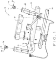
- Fig. 1 illustrates an exploded perspective view of a handle assembly 10 for use with a sewing machine (not illustrated).
- Handle assembly 10 includes components known throughout the art including grips 20 for users to grasp in steering the handle assembly 10, a casing 30 for including operative components therein, a post 40 to which a laser may be mounted, and LED light fixture 50 for illuminating a workspace for a user.
- handle assembly 10 operates in a manner known in the art for quilting, both traditional long-armed stitching methods and those including a pantograph pattern, where the pantograph pattern is traced by a laser, physical pointer, or other digital means.
- Fig. 1 further illustrates an enclosure member 60, which may be used to contain and secure various electronic, mechanical, and digital components for operating the sewing machine. Those components may be operated by a control interface 70.
- Control interface 70 is illustrated in Fig. 1 as exploding from grips 20, as switches 70.
- Control interface 70 may include a plurality of buttons, or alternatively switches, for controlling various aspects of the sewing machine. Switches 70 are illustrated in in Fig. 1 as each including two buttons 75. The means by which buttons 75 of switches 70 adjust the sewing machine features are means known in the art of electronics. For example, switches 70 and buttons 75 may be in electronic communication with a controller that adjusts the motor associated with the sewing machine to adjust stitching mode, speed, etc. (not illustrated).
- the settings that buttons 75 communicate to the controller are pre-determined by a user.
- the settings may be hard-wired and defined with factory settings.
- settings that the user may define include, but are not limited to, stitch speed and stitch mode (e.g. Constant, Basting, Regulated).
- stitch speed and stitch mode e.g. Constant, Basting, Regulated
- a user may define that pushing a first button 75 causes the sewing machine to switch to Constant mode at a speed of 20 stitches per inch, or alternatively, pushing a second button 75 causes the sewing machine to switch to Constant mode at a speed of 40 stitches per inch.
- the aforementioned buttons may be a toggled switch, such as buttons 75 of switch 70, or the buttons may be separate and independent buttons.
- the means by which a user may define the settings programmed for use with the sewing machine may be any means known throughout the art.
- the settings may be programmable on a computer, tablet, or mobile device, which may then be transferred to buttons 75 via a manner known in the art, for example a USB, Wi-Fi, Bluetooth, or other connection.
- buttons 75 may be transferred to buttons 75 via a manner known in the art, for example a USB, Wi-Fi, Bluetooth, or other connection.
- buttons 75 located elsewhere on the sewing machine for adjusting the settings associated with control interface 70.
- those settings may be implemented immediately. It should be noted that the settings may be implemented immediately, without the need to stop the machine. Thus, the settings may be implemented while the machine is operating or stopped.
- buttons 75 for adjusting settings associated with the sewing machine are embodied as switches 70, wherein each switch 70 includes two buttons 75.
- the buttons 75 of switches 70, or other control interface may be located elsewhere on handle assembly 10, for example casing 30.
- the control interface may be placed at any location so long as it is within reach of a user.
- the control interface 70, such as switches 70 with buttons 75 may alternatively be located at a rear set of handles associated with a rear portion of a quilting machine that is well-known in the art for being used in tracing pantograph patterns.
- the preferred embodiment includes two toggle switches 70, made up of four buttons 75 (two buttons 75 for each switch 70), for controlling sewing modes. However, embodiments are further envisioned wherein more or less toggle switches and/or buttons for controlling sewing modes could be included with the sewing machine.
- the sewing machine does not include buttons 75 for a control interface 70, and it instead includes a plurality of switches, knobs, or other foreseeable control interfaces which perform substantially similarly to the buttons 75 described herein above.
- the switches, knobs, or other foreseeable control interfaces may also be positioned at any location associated with the sewing machine as long as they are within reach of a user.
- sewing machines such as those described in the present application may include tablet devices, or tablets for use therewith.
- a Samsung Galaxy Tab 3 10.1 Android may be used with the sewing machine. Tablets are used with sewing machines to control a sewing machine by positioning needles, operating the laser used when tracing pantograph patterns, starting and stopping sewing, and many other functions.
- the tablet may be used to control the stitching modes and speeds in the manner above in place of buttons 75 or other control interfaces 70.
- the user may command a sewing machine to switch modes immediately upon direction, as previously described. Thus the modes may be switched while the machine is in operation or stopped.
- the modes which may be available to a user may be pre-set by a user. The user may define these pre-set modes using software of the application the tablet uses in operating the sewing machine.
- Fig. 2 is a screenshot 80 of the tablet as an operator may see it.
- screenshot 80 includes a top ribbon 90, where a variety of modes may be selected to automatically switch the mode in which the machine is operating, including user preset modes 100.
- User preset modes 100 may be programmed by the user via software associated with the tablet or in other manners known throughout the art. In the illustrated embodiment, there are two user preset modes 100 displayed, though alternative embodiments including more user preset modes 100 are foreseen.
- the screenshot further includes a mode section 110 where the mode in which the sewing machine is operating is displayed.
- a bottom ribbon 120 is also illustrated in Fig. 2 .
- Bottom ribbon 120 allows a user to assign various button 75 functions.
- the functions assigned to buttons 75 are (A) - ADJUST SETTING DOWN, (B) - ADJUST SETTING UP, (C) - START/STOP STITCHING, and (D) - MYSTITCH SELECT.
- MYSTITCH SELECT mode is preset mode 100 including speed and stitch regulating, though as set forth above the MYSTITCH SELECT mode is user programmable.
- setting (A) corresponds to one button 75 on one switch 70 shown in Fig. 1
- setting (B) corresponds to one button 75 on one switch 70 shown in Fig. 1
- setting (C) corresponds to one button 75 on one switch 70 shown in Fig. 1
- setting (D) corresponds to one button 75 on one switch 70 shown in Fig. 1 such that each setting corresponds to a single button 75.
- menu 130 displays frequently used operations, or settings, that a user may select from in assigning the various button functions via bottom ribbon 120.
Landscapes
- Engineering & Computer Science (AREA)
- Textile Engineering (AREA)
- Computer Hardware Design (AREA)
- Microelectronics & Electronic Packaging (AREA)
- Sewing Machines And Sewing (AREA)
Description
- This application claims priority and benefit of
U.S. Provisional Patent Application 61/981,949 filed April 21, 2014 - The present invention relates to sewing. In particular, the invention relates to particular styles of sewing that incorporate decorative stitching such as quilting. A quilt is a type of blanket typically having three layers: a decorative top layer, a middle layer of insulating material, and a backing layer. "Quilting" refers to the technique of joining these layers by stitches or ties.
- Traditional quilting was done by hand and was very labor intensive. The invention of the sewing machine changed that. Quilting evolved from production of functional blankets by specialized artisans into a popular hobby enjoyed by many.
- Quilting sewing machines typically have the ability to perform different modes of operation. Normally, these modes include Constant mode, Basting mode, and Regulated mode. The Constant mode operates at a set motor speed, regardless of how the user moves the machine. The Basting mode stitches at a large interval as the machine is moved, typically around 1" between stitches. Regulated mode varies the motor speed continually to maintain a set stitch length, regardless of how fast the user is moving the machine. Switching between these modes is normally performed by choosing a mode with some user interface environment.
- Each of the different modes has specific strengths and weaknesses depending on the operation being performed by the user. For instance, it is common for users to utilize Regulated mode when stitching large, sweeping patterns. It is common for users to utilize Constant mode when doing lots of small stitches for "filling" type operations. The normal process has been for the user to stop the machine, manually switch between modes, and then start stitching again in the new mode.
- Several years ago, the Coast Regulate mode was developed as a way for the machine to sense and automatically switch between Regulated and Constant modes. In Coast Regulate mode, the machine normally runs in Regulated mode. The machine measures whether the needed motor speed is above a set threshold. If the required motor speed falls below this threshold, then the machine recognizes that the user is slowing down to do "fill" work, etc. and switches to a Constant operation at a user-set speed. If the user speeds up the movement of the machine enough to go back above the threshold, the machine returns to Regulated operation. While this does work, many users find it difficult to correctly set the threshold so that they get the desired results.
US 4,876,976 describes an automatic quilting machine comprising a remote joystick that can be used by an operator to trace a pattern sewn into the fabric, a process controller comprising a memory to store information of the pattern traced through the joystick and selected locations on the quilt where the pattern is to be sewn into the fabric, wherein the process controller subsequently causes the apparatus to sew the desired pattern at each marked location on the fabric.
US 2010/186646 discloses a stitcher including a monitoring system having at least one sensor positioned below the fabric to monitor stitches placed in a fabric. - The present invention relates to a quilting machine, more specifically, to the stitching modes in which the quilting machine operates. In the present invention, the quilting or sewing machine may operate in a number of modes. For example, it may operate in Constant, Basting, or Regulated mode. The present invention includes a control interface, which may be switches including buttons. The preferred embodiment includes two buttons on each of two switches positioned on a handle for controlling the sewing machine. The buttons are programmable to control a specific mode in which the machine should be operating. Thus, when a user presses one of the buttons, the machine operation will change from the current mode to the alternative mode programmed to the pressed button.
- A user may press a button or other control interface, and thus switch the mode in which the machine is operated at any time, whether the machine is presently in operation or not. The settings that the buttons communicate to the machine may be hard-coded as pre-set when the machine is sent from the factory, or users may pre-set the settings to desired operating parameters. When the user pre-sets the settings, they may control aspects such as mode, speed, etc.
- In the accompanying drawings, which form a part of the specification and are to be read in conjunction therewith in which like reference numerals are used to indicate like or similar parts in the various views:
-
Fig. 1 is an exploded perspective view of handle assembly associated with a sewing machine -
Fig. 2 is a screenshot of a user interface associated with and for controlling various settings of a sewing machine. -
Fig. 3 is a second screenshot of a user interface associated with and for controlling various settings of a sewing machine. - The present invention is directed generally toward a method of switching modes of operation of a quilting, or sewing machine. More specifically, it is directed toward a method of switching modes of operation while the sewing machine is running, and wherein the modes of operation have been programmed by a user.
-
Fig. 1 illustrates an exploded perspective view of ahandle assembly 10 for use with a sewing machine (not illustrated).Handle assembly 10 includes components known throughout theart including grips 20 for users to grasp in steering thehandle assembly 10, acasing 30 for including operative components therein, apost 40 to which a laser may be mounted, andLED light fixture 50 for illuminating a workspace for a user. In operation,handle assembly 10 operates in a manner known in the art for quilting, both traditional long-armed stitching methods and those including a pantograph pattern, where the pantograph pattern is traced by a laser, physical pointer, or other digital means. -
Fig. 1 further illustrates anenclosure member 60, which may be used to contain and secure various electronic, mechanical, and digital components for operating the sewing machine. Those components may be operated by acontrol interface 70.Control interface 70 is illustrated inFig. 1 as exploding fromgrips 20, asswitches 70. -
Control interface 70 may include a plurality of buttons, or alternatively switches, for controlling various aspects of the sewing machine.Switches 70 are illustrated in inFig. 1 as each including twobuttons 75. The means by whichbuttons 75 ofswitches 70 adjust the sewing machine features are means known in the art of electronics. For example,switches 70 andbuttons 75 may be in electronic communication with a controller that adjusts the motor associated with the sewing machine to adjust stitching mode, speed, etc. (not illustrated). - In the present invention, the settings that
buttons 75 communicate to the controller are pre-determined by a user. Alternatively, the settings may be hard-wired and defined with factory settings. In the present embodiment, settings that the user may define include, but are not limited to, stitch speed and stitch mode (e.g. Constant, Basting, Regulated). For example, a user may define that pushing afirst button 75 causes the sewing machine to switch to Constant mode at a speed of 20 stitches per inch, or alternatively, pushing asecond button 75 causes the sewing machine to switch to Constant mode at a speed of 40 stitches per inch. The aforementioned buttons may be a toggled switch, such asbuttons 75 ofswitch 70, or the buttons may be separate and independent buttons. The means by which a user may define the settings programmed for use with the sewing machine may be any means known throughout the art. For example, the settings may be programmable on a computer, tablet, or mobile device, which may then be transferred tobuttons 75 via a manner known in the art, for example a USB, Wi-Fi, Bluetooth, or other connection. Alternatively there may be a control panel located elsewhere on the sewing machine for adjusting the settings associated withcontrol interface 70. When a user pushes abutton 75 ofswitch 70 associated with particular settings, those settings may be implemented immediately. It should be noted that the settings may be implemented immediately, without the need to stop the machine. Thus, the settings may be implemented while the machine is operating or stopped. - In the illustrated embodiment,
buttons 75 for adjusting settings associated with the sewing machine are embodied as switches 70, wherein eachswitch 70 includes twobuttons 75. In other foreseeable embodiments, thebuttons 75 ofswitches 70, or other control interface, may be located elsewhere onhandle assembly 10, forexample casing 30. The control interface may be placed at any location so long as it is within reach of a user. Thecontrol interface 70, such asswitches 70 withbuttons 75 may alternatively be located at a rear set of handles associated with a rear portion of a quilting machine that is well-known in the art for being used in tracing pantograph patterns. The preferred embodiment includes twotoggle switches 70, made up of four buttons 75 (twobuttons 75 for each switch 70), for controlling sewing modes. However, embodiments are further envisioned wherein more or less toggle switches and/or buttons for controlling sewing modes could be included with the sewing machine. - In one embodiment, the sewing machine does not include
buttons 75 for acontrol interface 70, and it instead includes a plurality of switches, knobs, or other foreseeable control interfaces which perform substantially similarly to thebuttons 75 described herein above. In this embodiment, the switches, knobs, or other foreseeable control interfaces may also be positioned at any location associated with the sewing machine as long as they are within reach of a user. - Presently, sewing machines such as those described in the present application may include tablet devices, or tablets for use therewith. In the present embodiment, a Samsung Galaxy Tab 3 10.1 Android may be used with the sewing machine. Tablets are used with sewing machines to control a sewing machine by positioning needles, operating the laser used when tracing pantograph patterns, starting and stopping sewing, and many other functions.
- In an alternative embodiment, the tablet may be used to control the stitching modes and speeds in the manner above in place of
buttons 75 or other control interfaces 70. In this embodiment, it should be noted that the user may command a sewing machine to switch modes immediately upon direction, as previously described. Thus the modes may be switched while the machine is in operation or stopped. It should further be noted that in this embodiment, the modes which may be available to a user may be pre-set by a user. The user may define these pre-set modes using software of the application the tablet uses in operating the sewing machine. -
Fig. 2 is ascreenshot 80 of the tablet as an operator may see it. In the illustrated embodiment,screenshot 80 includes atop ribbon 90, where a variety of modes may be selected to automatically switch the mode in which the machine is operating, including user presetmodes 100. Userpreset modes 100 may be programmed by the user via software associated with the tablet or in other manners known throughout the art. In the illustrated embodiment, there are two user presetmodes 100 displayed, though alternative embodiments including more user presetmodes 100 are foreseen. - The screenshot further includes a
mode section 110 where the mode in which the sewing machine is operating is displayed. Abottom ribbon 120 is also illustrated inFig. 2 .Bottom ribbon 120 allows a user to assignvarious button 75 functions. InFig. 2 , the functions assigned tobuttons 75 are (A) - ADJUST SETTING DOWN, (B) - ADJUST SETTING UP, (C) - START/STOP STITCHING, and (D) - MYSTITCH SELECT. In the illustrated embodiment, MYSTITCH SELECT mode ispreset mode 100 including speed and stitch regulating, though as set forth above the MYSTITCH SELECT mode is user programmable. - In the preferred embodiment, setting (A) corresponds to one
button 75 on oneswitch 70 shown inFig. 1 , setting (B) corresponds to onebutton 75 on oneswitch 70 shown inFig. 1 , setting (C) corresponds to onebutton 75 on oneswitch 70 shown inFig. 1 , and setting (D) corresponds to onebutton 75 on oneswitch 70 shown inFig. 1 such that each setting corresponds to asingle button 75. In alternative embodiments, there may be more settings from which to choose and/ormore control devices 70 to carry out those settings. For example, inFig. 3 , menu 130 displays frequently used operations, or settings, that a user may select from in assigning the various button functions viabottom ribbon 120. - From the foregoing, it will be seen that this invention is one well adapted to attain all the ends and objects hereinabove set forth together with other advantages which are obvious and which are inherent to the structure. It will be understood that certain features and sub combinations are of utility and may be employed without reference to other features and sub combinations. This is contemplated by and is within the scope of the claims. Since many possible embodiments of the invention may be made without departing from the scope thereof, it is also to be understood that all matters herein set forth or shown in the accompanying drawings are to be interpreted as illustrative and not limiting.
- The constructions described above and illustrated in the drawings are presented by way of example only and are not intended to limit the concepts and principles of the present invention. Thus, there has been shown and described several embodiments of a novel invention. As is evident from the foregoing description, certain aspects of the present invention are not limited by the particular details of the examples illustrated herein, and it is therefore contemplated that other modifications and applications, or equivalents thereof, will occur to those skilled in the art. The terms "having" and "including" and similar terms as used in the foregoing specification are used in the sense of "optional" or "may include" and not as "required". Many changes, modifications, variations and other uses and applications of the present construction will, however, become apparent to those skilled in the art after considering the specification and the accompanying drawings. All such changes, modifications, variations and other uses and applications which do not depart from the scope of the invention are deemed to be covered by the invention which is limited only by the claims which follow.
Claims (12)
- A system for regulating the operation of a sewing machine, said system comprising:at least one control interface (70); anda user interface (80) in communication with the at least one control interface (70) for programming modes of operation of said sewing machine to each of the at least one control interface (70),
characterized in that the system further comprises a handle assembly (10) for use with said sewing machine, the at least one control interface (70) being in communication with said handle assembly (10) for switching modes of operation of said sewing machine, wherein said modes of operation include a Constant mode, a Basting mode, or a Regulated mode and said control interface (70) switches modes of operation when said sewing machine is in operation, while it is running. - The system of claim 1, wherein the control interface (70) includes at least one switch.
- The system of claim 2, wherein the at least one switch (70) includes one or more buttons (75).
- The system of claim 3, wherein each of the one or more buttons are programmable via the user interface (80) to correspond to a mode of operation of the sewing machine.
- The system of claim 1, wherein the user interface (80) includes the at least one control interface (70) in communication with the handle assembly (10).
- The system of claim 1, wherein the control interface (70) and the user interface (80) are in communication via a wireless connection.
- The system of claim 1, wherein the control interface (70) is fixedly attached to the handle assembly (10).
- The system of claim 1, wherein the control interface (70) and the handle assembly (10) are in communication via a wireless connection.
- The system of claim 1, wherein the user interface (80) is programmable such that a user may program settings including at least one of stitch speed and stitch mode to the at least one control interface (70).
- The system of claim 1, wherein the user interface (80) is a tablet device.
- A method for switching modes of a sewing machine comprising the steps of:configuring a plurality of modes for sewing machine operation via a user interface (80), andassigning at least one of said plurality of modes for sewing machine operation to at least one control interface (70) of said sewing machine, the user interface (80) being in communication with the at least one control interface (70),characterized in that the at least one control interface (70) is in communication with a handle assembly (10), the modes of operation including a Constant mode, a Basting mode, or a Regulated mode, the method further comprising switching said sewing machine from one of said plurality of modes to a second of said plurality of modes when said sewing machine is in operation, while it is running.
- The method of claim 11, wherein the control interface (70) includes a plurality of switches, and wherein each of the plurality of switches includes a plurality of buttons (75), each of the plurality of buttons (75) corresponding to a mode for sewing machine operation.
Applications Claiming Priority (2)
| Application Number | Priority Date | Filing Date | Title |
|---|---|---|---|
| US201461981949P | 2014-04-21 | 2014-04-21 | |
| PCT/US2015/026640 WO2015164247A1 (en) | 2014-04-21 | 2015-04-20 | Stitching mode regulator |
Publications (3)
| Publication Number | Publication Date |
|---|---|
| EP3134569A1 EP3134569A1 (en) | 2017-03-01 |
| EP3134569A4 EP3134569A4 (en) | 2017-11-22 |
| EP3134569B1 true EP3134569B1 (en) | 2019-07-24 |
Family
ID=54321525
Family Applications (1)
| Application Number | Title | Priority Date | Filing Date |
|---|---|---|---|
| EP15782757.7A Active EP3134569B1 (en) | 2014-04-21 | 2015-04-20 | Stitching mode regulator and method for switching modes of a sewing machine |
Country Status (5)
| Country | Link |
|---|---|
| US (1) | US10060060B2 (en) |
| EP (1) | EP3134569B1 (en) |
| AU (1) | AU2015249996B2 (en) |
| CA (1) | CA2946555C (en) |
| WO (1) | WO2015164247A1 (en) |
Family Cites Families (16)
| Publication number | Priority date | Publication date | Assignee | Title |
|---|---|---|---|---|
| EP0016724B1 (en) * | 1979-03-15 | 1984-07-11 | Fritz Gegauf Ag Bernina-Nähmaschinenfabrik | Device for giving instructions for adjusting and fitting attachments to a sewing machine |
| JP2585594B2 (en) * | 1987-05-11 | 1997-02-26 | ペガサスミシン製造 株式会社 | Sewing machine thread tension device |
| US4876976A (en) * | 1988-07-18 | 1989-10-31 | Td Quilting Machinery | Automatic quilting machine and method for specialized quilting of patterns which can be controlled by a remote joystick and monitored on a video screen including pattern duplication through a reprogrammable computer |
| JP2004141471A (en) * | 2002-10-25 | 2004-05-20 | Janome Sewing Mach Co Ltd | Network connectable embroidery machine and network system |
| US20060112866A1 (en) * | 2004-12-01 | 2006-06-01 | Pfeifer Thomas A | Stitch regulator for a sewing machine |
| WO2006063381A1 (en) | 2004-12-15 | 2006-06-22 | John Watts | Improvements in quilting machines |
| JP4821984B2 (en) | 2006-05-24 | 2011-11-24 | ブラザー工業株式会社 | sewing machine |
| EP1878823B1 (en) * | 2006-07-10 | 2019-03-06 | BERNINA International AG | Method and device for representing sewing processes |
| US7552691B1 (en) | 2006-10-05 | 2009-06-30 | Martelli Enterprises, Inc. | Support and cassette apparatus and method |
| US8074590B2 (en) * | 2007-12-12 | 2011-12-13 | Arthur Bentley | Method and system for freehand and realtime quilting with a computer-controlled quilting machine |
| JP2009142379A (en) * | 2007-12-12 | 2009-07-02 | Juki Corp | sewing machine |
| US20100186646A1 (en) * | 2009-01-27 | 2010-07-29 | Gammill, Inc. | Stitch quality monitoring system |
| WO2011001289A2 (en) * | 2009-07-01 | 2011-01-06 | Alberto Landoni | Machine and method for sewing, embroidering, quilting and/or the like |
| JP2011083352A (en) * | 2009-10-14 | 2011-04-28 | Brother Industries Ltd | Sewing machine |
| US9267222B2 (en) | 2012-01-25 | 2016-02-23 | Abm International, Inc. | Method and apparatus for visualizing the position of an operating head relative to a workpiece |
| JP2013188264A (en) * | 2012-03-12 | 2013-09-26 | Brother Ind Ltd | Sewing machine |
-
2015
- 2015-04-20 AU AU2015249996A patent/AU2015249996B2/en active Active
- 2015-04-20 WO PCT/US2015/026640 patent/WO2015164247A1/en not_active Ceased
- 2015-04-20 US US14/690,903 patent/US10060060B2/en active Active
- 2015-04-20 CA CA2946555A patent/CA2946555C/en active Active
- 2015-04-20 EP EP15782757.7A patent/EP3134569B1/en active Active
Non-Patent Citations (1)
| Title |
|---|
| None * |
Also Published As
| Publication number | Publication date |
|---|---|
| EP3134569A1 (en) | 2017-03-01 |
| CA2946555C (en) | 2021-11-23 |
| US10060060B2 (en) | 2018-08-28 |
| EP3134569A4 (en) | 2017-11-22 |
| AU2015249996A1 (en) | 2016-11-10 |
| US20150299924A1 (en) | 2015-10-22 |
| WO2015164247A1 (en) | 2015-10-29 |
| AU2015249996B2 (en) | 2019-04-18 |
| CA2946555A1 (en) | 2015-10-29 |
Similar Documents
| Publication | Publication Date | Title |
|---|---|---|
| US9840796B2 (en) | Method and apparatus for visualizing the position of an operating head relative to a workpiece | |
| US7971543B2 (en) | Sewing machine and computer-readable recording medium storing sewing machine operation program | |
| JP5155610B2 (en) | Sewing method of decorative material on fabric, continuous cutting device and decorative sewing machine with cutting function | |
| JP2013188264A (en) | Sewing machine | |
| US20140290547A1 (en) | Cutting needle rotation device and sewing machine | |
| CN106894170B (en) | Sewing machine, needle number management system and needle number management method | |
| US7878133B2 (en) | Sewing machine and computer-readable recording medium storing sewing machine operation program | |
| JP2009011594A (en) | Embroidery method by sewing machine and sewing machine | |
| US10060060B2 (en) | Stitching mode regulator | |
| US8897907B2 (en) | Data generating device, sewing machine and non-transitory computer-readable medium storing control program for data generating device | |
| JP2014105401A (en) | Embroidery data generating device, sewing machine and embroidery data generating program | |
| JP2017046830A (en) | Sewing machine and control method of sewing machine | |
| JP2015066355A (en) | Sewing machine and method for controlling sewing machine | |
| US9315933B1 (en) | Stitch regulation apparatus and method | |
| JP2005052293A (en) | Sewing system | |
| US20130125803A1 (en) | Method and device for controlling sewing patterns of a sewing machine | |
| CN1847500B (en) | Differential feed sewing machine | |
| JP2010179014A (en) | Sewing machine and yarn tension establishment program | |
| JP6432899B2 (en) | Zigzag sewing machine and automatic pause control method of zigzag sewing machine | |
| US20160063892A1 (en) | Stitching teach device and application | |
| TW508391B (en) | Chain-stitch button sewing machine | |
| US9631309B2 (en) | Embroidery sewing machine having function of fixing interliner and material by basting | |
| JP2018042702A (en) | Sewing information editing device and method for controlling sewing information editing device | |
| JP4644523B2 (en) | sewing machine | |
| KR200484043Y1 (en) | Sewing machine |
Legal Events
| Date | Code | Title | Description |
|---|---|---|---|
| STAA | Information on the status of an ep patent application or granted ep patent |
Free format text: STATUS: THE INTERNATIONAL PUBLICATION HAS BEEN MADE |
|
| PUAI | Public reference made under article 153(3) epc to a published international application that has entered the european phase |
Free format text: ORIGINAL CODE: 0009012 |
|
| STAA | Information on the status of an ep patent application or granted ep patent |
Free format text: STATUS: REQUEST FOR EXAMINATION WAS MADE |
|
| 17P | Request for examination filed |
Effective date: 20161021 |
|
| AK | Designated contracting states |
Kind code of ref document: A1 Designated state(s): AL AT BE BG CH CY CZ DE DK EE ES FI FR GB GR HR HU IE IS IT LI LT LU LV MC MK MT NL NO PL PT RO RS SE SI SK SM TR |
|
| AX | Request for extension of the european patent |
Extension state: BA ME |
|
| DAV | Request for validation of the european patent (deleted) | ||
| DAX | Request for extension of the european patent (deleted) | ||
| A4 | Supplementary search report drawn up and despatched |
Effective date: 20171025 |
|
| RIC1 | Information provided on ipc code assigned before grant |
Ipc: D05B 19/10 20060101ALI20171019BHEP Ipc: D05B 19/12 20060101ALI20171019BHEP Ipc: D05B 19/08 20060101AFI20171019BHEP |
|
| STAA | Information on the status of an ep patent application or granted ep patent |
Free format text: STATUS: EXAMINATION IS IN PROGRESS |
|
| 17Q | First examination report despatched |
Effective date: 20181016 |
|
| GRAP | Despatch of communication of intention to grant a patent |
Free format text: ORIGINAL CODE: EPIDOSNIGR1 |
|
| STAA | Information on the status of an ep patent application or granted ep patent |
Free format text: STATUS: GRANT OF PATENT IS INTENDED |
|
| INTG | Intention to grant announced |
Effective date: 20190318 |
|
| GRAS | Grant fee paid |
Free format text: ORIGINAL CODE: EPIDOSNIGR3 |
|
| GRAA | (expected) grant |
Free format text: ORIGINAL CODE: 0009210 |
|
| STAA | Information on the status of an ep patent application or granted ep patent |
Free format text: STATUS: THE PATENT HAS BEEN GRANTED |
|
| AK | Designated contracting states |
Kind code of ref document: B1 Designated state(s): AL AT BE BG CH CY CZ DE DK EE ES FI FR GB GR HR HU IE IS IT LI LT LU LV MC MK MT NL NO PL PT RO RS SE SI SK SM TR |
|
| REG | Reference to a national code |
Ref country code: GB Ref legal event code: FG4D |
|
| REG | Reference to a national code |
Ref country code: CH Ref legal event code: EP |
|
| REG | Reference to a national code |
Ref country code: DE Ref legal event code: R096 Ref document number: 602015034401 Country of ref document: DE |
|
| REG | Reference to a national code |
Ref country code: AT Ref legal event code: REF Ref document number: 1158321 Country of ref document: AT Kind code of ref document: T Effective date: 20190815 |
|
| REG | Reference to a national code |
Ref country code: IE Ref legal event code: FG4D |
|
| REG | Reference to a national code |
Ref country code: NL Ref legal event code: MP Effective date: 20190724 |
|
| REG | Reference to a national code |
Ref country code: LT Ref legal event code: MG4D |
|
| REG | Reference to a national code |
Ref country code: AT Ref legal event code: MK05 Ref document number: 1158321 Country of ref document: AT Kind code of ref document: T Effective date: 20190724 |
|
| PG25 | Lapsed in a contracting state [announced via postgrant information from national office to epo] |
Ref country code: FI Free format text: LAPSE BECAUSE OF FAILURE TO SUBMIT A TRANSLATION OF THE DESCRIPTION OR TO PAY THE FEE WITHIN THE PRESCRIBED TIME-LIMIT Effective date: 20190724 Ref country code: SE Free format text: LAPSE BECAUSE OF FAILURE TO SUBMIT A TRANSLATION OF THE DESCRIPTION OR TO PAY THE FEE WITHIN THE PRESCRIBED TIME-LIMIT Effective date: 20190724 Ref country code: PT Free format text: LAPSE BECAUSE OF FAILURE TO SUBMIT A TRANSLATION OF THE DESCRIPTION OR TO PAY THE FEE WITHIN THE PRESCRIBED TIME-LIMIT Effective date: 20191125 Ref country code: NO Free format text: LAPSE BECAUSE OF FAILURE TO SUBMIT A TRANSLATION OF THE DESCRIPTION OR TO PAY THE FEE WITHIN THE PRESCRIBED TIME-LIMIT Effective date: 20191024 Ref country code: AT Free format text: LAPSE BECAUSE OF FAILURE TO SUBMIT A TRANSLATION OF THE DESCRIPTION OR TO PAY THE FEE WITHIN THE PRESCRIBED TIME-LIMIT Effective date: 20190724 Ref country code: HR Free format text: LAPSE BECAUSE OF FAILURE TO SUBMIT A TRANSLATION OF THE DESCRIPTION OR TO PAY THE FEE WITHIN THE PRESCRIBED TIME-LIMIT Effective date: 20190724 Ref country code: BG Free format text: LAPSE BECAUSE OF FAILURE TO SUBMIT A TRANSLATION OF THE DESCRIPTION OR TO PAY THE FEE WITHIN THE PRESCRIBED TIME-LIMIT Effective date: 20191024 Ref country code: LT Free format text: LAPSE BECAUSE OF FAILURE TO SUBMIT A TRANSLATION OF THE DESCRIPTION OR TO PAY THE FEE WITHIN THE PRESCRIBED TIME-LIMIT Effective date: 20190724 Ref country code: NL Free format text: LAPSE BECAUSE OF FAILURE TO SUBMIT A TRANSLATION OF THE DESCRIPTION OR TO PAY THE FEE WITHIN THE PRESCRIBED TIME-LIMIT Effective date: 20190724 |
|
| PG25 | Lapsed in a contracting state [announced via postgrant information from national office to epo] |
Ref country code: AL Free format text: LAPSE BECAUSE OF FAILURE TO SUBMIT A TRANSLATION OF THE DESCRIPTION OR TO PAY THE FEE WITHIN THE PRESCRIBED TIME-LIMIT Effective date: 20190724 Ref country code: LV Free format text: LAPSE BECAUSE OF FAILURE TO SUBMIT A TRANSLATION OF THE DESCRIPTION OR TO PAY THE FEE WITHIN THE PRESCRIBED TIME-LIMIT Effective date: 20190724 Ref country code: IS Free format text: LAPSE BECAUSE OF FAILURE TO SUBMIT A TRANSLATION OF THE DESCRIPTION OR TO PAY THE FEE WITHIN THE PRESCRIBED TIME-LIMIT Effective date: 20191124 Ref country code: GR Free format text: LAPSE BECAUSE OF FAILURE TO SUBMIT A TRANSLATION OF THE DESCRIPTION OR TO PAY THE FEE WITHIN THE PRESCRIBED TIME-LIMIT Effective date: 20191025 Ref country code: RS Free format text: LAPSE BECAUSE OF FAILURE TO SUBMIT A TRANSLATION OF THE DESCRIPTION OR TO PAY THE FEE WITHIN THE PRESCRIBED TIME-LIMIT Effective date: 20190724 Ref country code: ES Free format text: LAPSE BECAUSE OF FAILURE TO SUBMIT A TRANSLATION OF THE DESCRIPTION OR TO PAY THE FEE WITHIN THE PRESCRIBED TIME-LIMIT Effective date: 20190724 |
|
| PG25 | Lapsed in a contracting state [announced via postgrant information from national office to epo] |
Ref country code: TR Free format text: LAPSE BECAUSE OF FAILURE TO SUBMIT A TRANSLATION OF THE DESCRIPTION OR TO PAY THE FEE WITHIN THE PRESCRIBED TIME-LIMIT Effective date: 20190724 |
|
| PG25 | Lapsed in a contracting state [announced via postgrant information from national office to epo] |
Ref country code: EE Free format text: LAPSE BECAUSE OF FAILURE TO SUBMIT A TRANSLATION OF THE DESCRIPTION OR TO PAY THE FEE WITHIN THE PRESCRIBED TIME-LIMIT Effective date: 20190724 Ref country code: DK Free format text: LAPSE BECAUSE OF FAILURE TO SUBMIT A TRANSLATION OF THE DESCRIPTION OR TO PAY THE FEE WITHIN THE PRESCRIBED TIME-LIMIT Effective date: 20190724 Ref country code: IT Free format text: LAPSE BECAUSE OF FAILURE TO SUBMIT A TRANSLATION OF THE DESCRIPTION OR TO PAY THE FEE WITHIN THE PRESCRIBED TIME-LIMIT Effective date: 20190724 Ref country code: RO Free format text: LAPSE BECAUSE OF FAILURE TO SUBMIT A TRANSLATION OF THE DESCRIPTION OR TO PAY THE FEE WITHIN THE PRESCRIBED TIME-LIMIT Effective date: 20190724 Ref country code: PL Free format text: LAPSE BECAUSE OF FAILURE TO SUBMIT A TRANSLATION OF THE DESCRIPTION OR TO PAY THE FEE WITHIN THE PRESCRIBED TIME-LIMIT Effective date: 20190724 |
|
| PG25 | Lapsed in a contracting state [announced via postgrant information from national office to epo] |
Ref country code: CZ Free format text: LAPSE BECAUSE OF FAILURE TO SUBMIT A TRANSLATION OF THE DESCRIPTION OR TO PAY THE FEE WITHIN THE PRESCRIBED TIME-LIMIT Effective date: 20190724 Ref country code: SM Free format text: LAPSE BECAUSE OF FAILURE TO SUBMIT A TRANSLATION OF THE DESCRIPTION OR TO PAY THE FEE WITHIN THE PRESCRIBED TIME-LIMIT Effective date: 20190724 Ref country code: IS Free format text: LAPSE BECAUSE OF FAILURE TO SUBMIT A TRANSLATION OF THE DESCRIPTION OR TO PAY THE FEE WITHIN THE PRESCRIBED TIME-LIMIT Effective date: 20200224 Ref country code: SK Free format text: LAPSE BECAUSE OF FAILURE TO SUBMIT A TRANSLATION OF THE DESCRIPTION OR TO PAY THE FEE WITHIN THE PRESCRIBED TIME-LIMIT Effective date: 20190724 |
|
| REG | Reference to a national code |
Ref country code: DE Ref legal event code: R097 Ref document number: 602015034401 Country of ref document: DE |
|
| PLBE | No opposition filed within time limit |
Free format text: ORIGINAL CODE: 0009261 |
|
| STAA | Information on the status of an ep patent application or granted ep patent |
Free format text: STATUS: NO OPPOSITION FILED WITHIN TIME LIMIT |
|
| PG2D | Information on lapse in contracting state deleted |
Ref country code: IS |
|
| 26N | No opposition filed |
Effective date: 20200603 |
|
| PG25 | Lapsed in a contracting state [announced via postgrant information from national office to epo] |
Ref country code: SI Free format text: LAPSE BECAUSE OF FAILURE TO SUBMIT A TRANSLATION OF THE DESCRIPTION OR TO PAY THE FEE WITHIN THE PRESCRIBED TIME-LIMIT Effective date: 20190724 |
|
| REG | Reference to a national code |
Ref country code: DE Ref legal event code: R119 Ref document number: 602015034401 Country of ref document: DE |
|
| PG25 | Lapsed in a contracting state [announced via postgrant information from national office to epo] |
Ref country code: MC Free format text: LAPSE BECAUSE OF FAILURE TO SUBMIT A TRANSLATION OF THE DESCRIPTION OR TO PAY THE FEE WITHIN THE PRESCRIBED TIME-LIMIT Effective date: 20190724 |
|
| REG | Reference to a national code |
Ref country code: CH Ref legal event code: PL |
|
| PG25 | Lapsed in a contracting state [announced via postgrant information from national office to epo] |
Ref country code: LI Free format text: LAPSE BECAUSE OF NON-PAYMENT OF DUE FEES Effective date: 20200430 Ref country code: CH Free format text: LAPSE BECAUSE OF NON-PAYMENT OF DUE FEES Effective date: 20200430 Ref country code: DE Free format text: LAPSE BECAUSE OF NON-PAYMENT OF DUE FEES Effective date: 20201103 Ref country code: FR Free format text: LAPSE BECAUSE OF NON-PAYMENT OF DUE FEES Effective date: 20200430 Ref country code: LU Free format text: LAPSE BECAUSE OF NON-PAYMENT OF DUE FEES Effective date: 20200420 |
|
| REG | Reference to a national code |
Ref country code: BE Ref legal event code: MM Effective date: 20200430 |
|
| PG25 | Lapsed in a contracting state [announced via postgrant information from national office to epo] |
Ref country code: BE Free format text: LAPSE BECAUSE OF NON-PAYMENT OF DUE FEES Effective date: 20200430 |
|
| PG25 | Lapsed in a contracting state [announced via postgrant information from national office to epo] |
Ref country code: IE Free format text: LAPSE BECAUSE OF NON-PAYMENT OF DUE FEES Effective date: 20200420 |
|
| PG25 | Lapsed in a contracting state [announced via postgrant information from national office to epo] |
Ref country code: MT Free format text: LAPSE BECAUSE OF FAILURE TO SUBMIT A TRANSLATION OF THE DESCRIPTION OR TO PAY THE FEE WITHIN THE PRESCRIBED TIME-LIMIT Effective date: 20190724 Ref country code: CY Free format text: LAPSE BECAUSE OF FAILURE TO SUBMIT A TRANSLATION OF THE DESCRIPTION OR TO PAY THE FEE WITHIN THE PRESCRIBED TIME-LIMIT Effective date: 20190724 |
|
| PG25 | Lapsed in a contracting state [announced via postgrant information from national office to epo] |
Ref country code: MK Free format text: LAPSE BECAUSE OF FAILURE TO SUBMIT A TRANSLATION OF THE DESCRIPTION OR TO PAY THE FEE WITHIN THE PRESCRIBED TIME-LIMIT Effective date: 20190724 |
|
| PGFP | Annual fee paid to national office [announced via postgrant information from national office to epo] |
Ref country code: GB Payment date: 20250428 Year of fee payment: 11 |