EP3133956B1 - Product application device - Google Patents
Product application device Download PDFInfo
- Publication number
- EP3133956B1 EP3133956B1 EP15726661.0A EP15726661A EP3133956B1 EP 3133956 B1 EP3133956 B1 EP 3133956B1 EP 15726661 A EP15726661 A EP 15726661A EP 3133956 B1 EP3133956 B1 EP 3133956B1
- Authority
- EP
- European Patent Office
- Prior art keywords
- substance
- air
- enclosure
- vessel
- applying
- Prior art date
- Legal status (The legal status is an assumption and is not a legal conclusion. Google has not performed a legal analysis and makes no representation as to the accuracy of the status listed.)
- Active
Links
Images








Classifications
-
- A—HUMAN NECESSITIES
- A45—HAND OR TRAVELLING ARTICLES
- A45D—HAIRDRESSING OR SHAVING EQUIPMENT; EQUIPMENT FOR COSMETICS OR COSMETIC TREATMENTS, e.g. FOR MANICURING OR PEDICURING
- A45D34/00—Containers or accessories specially adapted for handling liquid toiletry or cosmetic substances, e.g. perfumes
- A45D34/04—Appliances specially adapted for applying liquid, e.g. using roller or ball
- A45D34/041—Appliances specially adapted for applying liquid, e.g. using roller or ball using a roller, a disc or a ball
-
- A—HUMAN NECESSITIES
- A45—HAND OR TRAVELLING ARTICLES
- A45D—HAIRDRESSING OR SHAVING EQUIPMENT; EQUIPMENT FOR COSMETICS OR COSMETIC TREATMENTS, e.g. FOR MANICURING OR PEDICURING
- A45D34/00—Containers or accessories specially adapted for handling liquid toiletry or cosmetic substances, e.g. perfumes
- A45D34/04—Appliances specially adapted for applying liquid, e.g. using roller or ball
-
- A—HUMAN NECESSITIES
- A45—HAND OR TRAVELLING ARTICLES
- A45D—HAIRDRESSING OR SHAVING EQUIPMENT; EQUIPMENT FOR COSMETICS OR COSMETIC TREATMENTS, e.g. FOR MANICURING OR PEDICURING
- A45D40/00—Casings or accessories specially adapted for storing or handling solid or pasty toiletry or cosmetic substances, e.g. shaving soaps or lipsticks
- A45D40/02—Casings wherein movement of the lipstick or like solid is a sliding movement
-
- A—HUMAN NECESSITIES
- A45—HAND OR TRAVELLING ARTICLES
- A45D—HAIRDRESSING OR SHAVING EQUIPMENT; EQUIPMENT FOR COSMETICS OR COSMETIC TREATMENTS, e.g. FOR MANICURING OR PEDICURING
- A45D40/00—Casings or accessories specially adapted for storing or handling solid or pasty toiletry or cosmetic substances, e.g. shaving soaps or lipsticks
- A45D40/02—Casings wherein movement of the lipstick or like solid is a sliding movement
- A45D40/04—Casings wherein movement of the lipstick or like solid is a sliding movement effected by a screw
-
- A—HUMAN NECESSITIES
- A45—HAND OR TRAVELLING ARTICLES
- A45D—HAIRDRESSING OR SHAVING EQUIPMENT; EQUIPMENT FOR COSMETICS OR COSMETIC TREATMENTS, e.g. FOR MANICURING OR PEDICURING
- A45D40/00—Casings or accessories specially adapted for storing or handling solid or pasty toiletry or cosmetic substances, e.g. shaving soaps or lipsticks
- A45D40/26—Appliances specially adapted for applying pasty paint, e.g. using roller, using a ball
-
- A—HUMAN NECESSITIES
- A45—HAND OR TRAVELLING ARTICLES
- A45D—HAIRDRESSING OR SHAVING EQUIPMENT; EQUIPMENT FOR COSMETICS OR COSMETIC TREATMENTS, e.g. FOR MANICURING OR PEDICURING
- A45D40/00—Casings or accessories specially adapted for storing or handling solid or pasty toiletry or cosmetic substances, e.g. shaving soaps or lipsticks
- A45D40/26—Appliances specially adapted for applying pasty paint, e.g. using roller, using a ball
- A45D40/261—Appliances specially adapted for applying pasty paint, e.g. using roller, using a ball using a ball, a roller or the like
-
- B—PERFORMING OPERATIONS; TRANSPORTING
- B05—SPRAYING OR ATOMISING IN GENERAL; APPLYING FLUENT MATERIALS TO SURFACES, IN GENERAL
- B05C—APPARATUS FOR APPLYING FLUENT MATERIALS TO SURFACES, IN GENERAL
- B05C21/00—Accessories or implements for use in connection with applying liquids or other fluent materials to surfaces, not provided for in groups B05C1/00 - B05C19/00
-
- B—PERFORMING OPERATIONS; TRANSPORTING
- B05—SPRAYING OR ATOMISING IN GENERAL; APPLYING FLUENT MATERIALS TO SURFACES, IN GENERAL
- B05C—APPARATUS FOR APPLYING FLUENT MATERIALS TO SURFACES, IN GENERAL
- B05C9/00—Apparatus or plant for applying liquid or other fluent material to surfaces by means not covered by any preceding group, or in which the means of applying the liquid or other fluent material is not important
- B05C9/08—Apparatus or plant for applying liquid or other fluent material to surfaces by means not covered by any preceding group, or in which the means of applying the liquid or other fluent material is not important for applying liquid or other fluent material and performing an auxiliary operation
- B05C9/14—Apparatus or plant for applying liquid or other fluent material to surfaces by means not covered by any preceding group, or in which the means of applying the liquid or other fluent material is not important for applying liquid or other fluent material and performing an auxiliary operation the auxiliary operation involving heating or cooling
-
- A—HUMAN NECESSITIES
- A45—HAND OR TRAVELLING ARTICLES
- A45D—HAIRDRESSING OR SHAVING EQUIPMENT; EQUIPMENT FOR COSMETICS OR COSMETIC TREATMENTS, e.g. FOR MANICURING OR PEDICURING
- A45D34/00—Containers or accessories specially adapted for handling liquid toiletry or cosmetic substances, e.g. perfumes
- A45D2034/005—Containers or accessories specially adapted for handling liquid toiletry or cosmetic substances, e.g. perfumes with a cartridge
-
- A—HUMAN NECESSITIES
- A45—HAND OR TRAVELLING ARTICLES
- A45D—HAIRDRESSING OR SHAVING EQUIPMENT; EQUIPMENT FOR COSMETICS OR COSMETIC TREATMENTS, e.g. FOR MANICURING OR PEDICURING
- A45D2200/00—Details not otherwise provided for in A45D
- A45D2200/15—Temperature
- A45D2200/155—Heating or cooling means, i.e. for storing or applying cosmetic products at a predetermined temperature
-
- A—HUMAN NECESSITIES
- A45—HAND OR TRAVELLING ARTICLES
- A45D—HAIRDRESSING OR SHAVING EQUIPMENT; EQUIPMENT FOR COSMETICS OR COSMETIC TREATMENTS, e.g. FOR MANICURING OR PEDICURING
- A45D2200/00—Details not otherwise provided for in A45D
- A45D2200/20—Additional enhancing means
Definitions
- Antiperspirants and deodorants are common everyday consumables that have been sold for many years and come in several common forms of delivery including aerosol sprays sold in cans, liquids in rollerball, solid stick and gel form. This is not an exhaustive list as other less popular forms exist.
- Antiperspirants contain an active ingredient that is used to block the sweat ducts and prevent perspiration. There are different types of active ingredient but most are Aluminum salt based like Aluminum Chloride.
- Aerosol - very common delivery method that is mainly used in Europe. Aerosol delivery has the benefit of delivering a very thin layer of product and is best associated with quick drying times. Consumers however have less control over the accuracy of delivery due to the nature of a fine mist and also it can be unpleasant when sprayed in confined spaces.
- Solid Stick - a method developed to address some concerns with drying times.
- the chemical formula comes in a solid format by the addition of waxes. Although this product when rubbed onto the skin may initially feel drier than a liquid, consumers are faced with other shortfalls. Immediate staining of clothes, especially dark garments is very common. The waxes that make the solid form can cause the formula to coagulate together and be difficult to remove even with soaps.
- Gel form - A more recent development to improve other product shortfalls. Gels are typically clear so don't give immediate staining, although their active ingredient when combined with sweat will cause staining of clothes. A gel dries quicker than a liquid since it is already in a less liquid form. Despite this, the drying times can be high with 5-10 minutes not uncommon. Delivery mechanisms of gels are typically crude with a form of pressure (plunger) forcing the gel through holes onto an applicator.
- rollerball - This form is most associated with the liquid form of formula.
- the rollerball is good for keeping the formula airtight and to a degree allows for quite a controlled amount of delivery of formula.
- Liquid antiperspirant is often reviewed as the most effective. Whilst effectiveness is actually associated with the percentage of the active aluminum (or other) ingredient that makes up the formula because the delivery is a liquid (much like the gel forms) the consumer can perhaps apply this more carefully. Liquid antiperspirants and deodorants delivered in this method still have high drying times, where 5-10 minutes is not uncommon.
- Packaging is an environmental concern for many consumers. As antiperspirants and deodorants are mostly disposable items with a high degree of plastics and metals (for aerosols) the safe disposal of these packages is an environmental concern.
- Document EP2090370 discloses a device for spraying a cosmetic or dermatological composition, comprising: an ultrasound or electrostatic spray head; an airflow generator for creating a stream of air for entraining a spray of composition particles atomized by the spray head; and a conditioning device for modifying the temperature of the outgoing stream of air, the conditioning device being placed upstream from the airflow generator.
- a device according to claim 1 and a method according to claim 15 for shortening the drying time of a moist substance such as a liquid, cream or gel is disclosed.
- the device contains the substance to be applied along with the mechanism for shortening the drying time.
- the device can be designed to attach to an existing vessel containing the moist substance to be applied.
- the device combines a system to move air with an applicator for antiperspirant or deodorant.
- the device results in vastly improved drying time of the substance or formula on the skin.
- the device can be part mechanical and part electrically powered by means of a power supply, in this case a battery.
- the device uses well-known principles of fluid dynamics to create an airflow that moves across the surface of the skin and reduces the drying time of liquids and gel forms of antiperspirant and deodorant.
- a coanda surface is a surface close to the exit of the airflow, in this case the air outlet collar, where airflow demonstrates the coanda effect. The air essentially hugs the contours of the coanda surface as it moves across it.
- Fluid dynamic principles are also used to improve the volume of air moved by the device utilizing a multiplier effect. This is achieved by way of the Venturi-Ejector principle. Airflow is deliberately manipulated to increase velocity and decrease pressure, which has the effect of drawing air from the space surrounding the device into the main enclosure / housing and entraining the air.
- the device is intended to be highly portable and small.
- a design described in detail below is similar in size to many disposable antiperspirants / deodorant containers sold today and is only limited by parts currently available.
- This device significantly reduces the drying time of the antiperspirants and deodorant. And when the device is combined with a proprietary formula it vastly improves the drying time of any typical gel or liquid antiperspirant or deodorant.
- the device features exchangeable vessels of antiperspirant or deodorant formula that will be disposed of or recycled once the formula is exhausted.
- the vessels can also be designed to be refilled.
- This exchangeable or refillable feature will allow for less wasteful packaging but also empower consumer choice as to the scent and formula strength including chemical active ingredient versus more natural formula.
- Other embodiments include: drawing the air away from the surface on which the substance is applied; drawing air away and simultaneously move air across the surface; drawing air from the sides of the device with air movement / delivery mechanism and air outlet on the bottom of the device; using a light source to quicken the drying time of the substance; and using a heat source to quicken the drying time of the substance.
- Carrier The chemical formula that actually carries the antiperspirant or deodorant active ingredient. It is this carrier that needs to evaporate on the skin for it to feel dry.
- the device includes a vessel containing the substance to be applied or can be attached to a vessel.
- the vessel can be a vessel created by others or a vessel included in the design of the device.
- An applicator head is mounted or attached on a top of the vessel.
- the device includes an enclosure or housing and can be mounted with the vessel either by enclosing the vessel or attaching to the vessel.
- a mechanism to create and deliver a form of energy is located in the housing and directed toward the applicator head. Many forms of energy are usable including gas or air movement, heat, light, or any combination of those energy forms.
- the power source for the mechanism is chosen based on power required for the actual mechanism.
- Examples of power sources are an electric power source or an air or other gas source. If the power source is located within the device a battery can be used or a pressurized container of gas/air. A control module including control devices as warranted are included in or on the housing. In other embodiments the power source is external to the outer wall of the enclosure for the device. When the power source is located external to the device a power cord or hose is extended from i the enclosure to the power source. The power source can even be a user blowing into a hose connected to the enclosure..
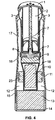
- Figure 4 shows the cross section front view and Figure 2 the rear view.
- the applicator control 5 is moved by the user and a mechanism for delivery of the formula to the applicator head 7 translates movement into an upwards movement of a plunger or equivalent in order to cause pressure on the antiperspirant or deodorant gel in the antiperspirant/deodorant vessel or capsule 2.
- the resulting pressure moves the gel towards the applicator head 1 and onto the user by way of one or more opening such as small apertures in the surface of the applicator head 1.
- the applicator control 5 may be a button, wheel, sliding type switch or other means for the user interacting with the device.
- Possible mechanisms for delivery of the formula to the applicator head 7 include a screw type mechanism, a jacking or racking mechanism, a sliding push mechanism, a spring or other means known to those skilled in delivery mechanisms.
- the applicator head 1 is used to apply the antiperspirant or deodorant to the body with the shape of the applicator head 1 helping to spread the product evenly onto the surface of the skin. It is envisaged that the applicator head 1 will be attached to the antiperspirant/deodorant vessel or capsule 2 to form one unit although this could also be two distinct replaceable pieces.
- an alternative applicator surface could be employed such as a standard rollerball attached to a disposable or refillable vessel.
- the current design makes great use of the shape of the applicator head in order to create a coanda surface to help improve performance. Any alternative applicator surface would come with a different performance.
- An alternative applicator such as a rollerball could also eliminate the need for the mechanism for delivery of the formula to the applicator head.
- Figure 1 shows components of a control circuit for the fan including power/control button(s) 6.
- Figure 4 shows a control module 9, a power source 10 and a fan unit 13. Electrical connections between the devices in the control module utilize wiring or other types of electrically conducting connectors.
- the power/control button(s) 6 can be used to control the on/off and regulate the speed of airflow.
- the power/control button(s) 6 activates an electric fan unit 13.
- the fan unit 13 is a Vein Axial Flow fan using DC power.
- the device can be configured to utilize AC power. It is also envisaged that another embodiment may be designed to allow connection to an external power source as an alternative to the Power Source 10. Other embodiments utilize different air movement devices such as a bladeless device.
- the air movement / delivery mechanism is compressed gas from a pressurized gas container, in which case an electrical control circuit may not be needed.
- a tube / hose can be provided to allow the user to blow air which is directed to the area of application of the substance to the user's surface.
- the power/control button(s) 6 are a means for the user to activate and control the device. In other embodiments the power/control button(s) 6 utilize capacitive or resistive touch sensor as a means of interaction. The power/control button(s) 6 may also use acoustic touch sensor.
- the control module 9 controls the device and can be designed to allow programming for control of the device.
- the control module 9 may control charging of the power source to increase power source life and make charging a safe process. It is also used to control the on/off and speed of the device.
- the control module 9 also can be programmed to control a visual alert utilizing one or more light emitting diode (LED) or some form of electronic display such as a liquid crystal display (LCD), organic light -emitting diode display (OLED), or an active-matrix organic light-emitting diode display (AMOLED).
- LED light emitting diode
- LCD liquid crystal display
- OLED organic light -emitting diode display
- AMOLED active-matrix organic light-emitting diode display
- the visual alert can indicate information such as speed of the device air delivery, power source charging indicator, reserve of power source and the volume of deodorant/antiperspirant left in the antiperspirant/deodorant vessel or capsule 2.
- the display indicates how dry the deodorant/antiperspirant is on the skin. It is also envisaged that an audible alert could be used so the user could be aware for example that the power source energy is low and needs charging, that the deodorant is dry, that the device is being charged, or that the antiperspirant/deodorant vessel or capsule 2 is almost empty.
- To activate all of the alerts appropriate well known sensors are required in the control circuit such as voltage, humidity, pressure, etc.
- Figure 3 shows a charging port 22, which is connected to the control module 9 by means of wires or other electrical conducting material.
- the enclosure has a lower section 15 and bottom end, a middle section 16, and an upper section 17 with a top end.
- the fan unit 13 once activated draws air from the surroundings by way of the air intake 14 located at the bottom end of the lower section 15. This air is moved through an air channel 12 between an inner wall of the enclosure 11 and the core section 18 inside of the enclosure 11.
- the core section 18 houses the power source 10, control module 9, a vessel containing the substance to be applied 26, a mechanism 7 for delivery of formula to applicator head 1, and appropriate electrical connections.
- An inward taper of the enclosure 11 creates a reduction in annular cross sectional area in the air channel 12 as the air advances toward the outlet collar 3. This looks like a taper or pinch of the sidewalls.
- the channel 12 After passing the air channel throat 8 the channel 12 features an outward taper or flare design allowing the fast moving air to expand.
- the faster moving air has lower pressure as it passes the ejector inlets 4.
- the 1 Venturi effect of the fast moving lower pressure air pulls in air from air surrounding the enclosure 11 through the ejector inlets 4 and into the channel 12..
- This air becomes entrained air 20 and exits at the air outlet collar 3 along with air that is driven through the air channel 12 by the fan unit 13.
- the result of the Venturi-Ejector principle is a multiplier effect of air moved.
- the volume of air that exits the air outlet collar 3 is greater than that which is moved by the fan unit 13.
- the air outlet collar 3 located in the upper section 17 and top end of the enclosure 11 is an aperture that surrounds the applicator head 1 such that air is delivered around the entire perimeter of the applicator head 1.
- the total surface area of the air outlet collar 3 is what determines the airspeed and pressure and will have an optimum efficient size for any given type of fan unit or other mechanism causing the movement of air in the main unit.
- the air outlet collar 3 in one embodiment surrounds the applicator head 1 like a collar but other embodiments utilize other designs such as a simple air flow hole or holes in varying shapes and sizes.
- the first variable to consider is the amount of reduction in annular area at the air channel throat 8. The greater the reduction of the area of the air channel at this point the faster will be the air speed and resulting pressure drop, however this is limited by the capability of the air movement mechanism being utilized. If a fan unit 13 is utilized, the torque capability of the fan unit 13 must be considered. If the area is too small it will result in back pressure on the fan unit 13 which must be considered.
- the number of ejector inlets 4 can be varied as desired since the principle that is important is the surface area of inlet as a percentage of the annular area at the air channel throat 8. This is designed to have an efficient ratio to maximize airflow.
- the angle of the enclosure 11 design where it flares outward after the air channel throat 8 is typically between 10-15 degrees to maximize efficiency of entrained air.
- FIG. 1 -6 Other embodiments feature different designs to multiply the air.
- a more traditional Venturi design could be used where the air attracted to the low-pressure zone takes place at a different location of the enclosure for instance closer to the fan unit 13.
- the embodiment shown in figures 1 -6 utilizes ejector inlets 4 that come after the pinch in the body to the direction of airflow. This is the Venturi-Ejector principle.
- Other fluid dynamics principles can be used to result in a similar effect to multiply air moved by entraining surrounding air.
- Convection decreases localized humidity caused by the evaporation of the carrier in the air around the skin application area until equilibrium of humidity is reached between the skin and the air around it. Moving air means that equilibrium is not reached which would slow the rate of evaporation, as saturated air will not hold any more carrier molecules.
- a differential gradient facilitates effective evaporation and also prevents gaseous carrier to condense back into the liquid form on the skin. Air that is moved across the surface of the skin will result in quicker drying times that air aimed directly perpendicular to the skin surface.
- the device disclosed facilitates the application of antiperspirant or deodorant and drying as quickly as possible.
- the design has therefore been made such that the multiplied air that exits at the air outlet collar 3 directs air movement across the skin to improve drying.
- the applicator head 1 is designed to create a coanda surface at the point of the air outlet collar 3.
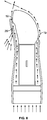
- the arrows in Figure 6 depict the airflow.
- Figure 6 depicts a side cross section, the coanda airflow takes place around the total circumference of the applicator head 1.
- the resulting coanda airflow reduces the drying time of the carrier of the formula antiperspirant or deodorant as described above in the convection principle. It is perfectly possible that alternate embodiments would not use a coanda surface as whilst this improves drying it does add to the complication of design.
- the Venturi-Ejector and Coanda Surface have the combined effect of making the air moved by the fan unit 13 feel softer on the skin but result in a increased volume of air moving in a direction to greatly reduce the drying time. It has also been envisaged that the single use or combined use of a Vortex of air could be used to achieve similar results.
- sensors to monitor parameters such as pressure, voltage, current, air flow, and humidity. These sensors can be used for indication or operational control by the control module 9.
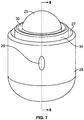
- FIG. 7 & 8 depict an alternative embodiment to demonstrate this possibility. Air is drawn away from the surface via air intake 27 and then pushed back to the surface via the air outlet 30. In this case the air is both withdrawn and moved back to the same surface. Air could also be just withdrawn via the air intake 27 and the air outlet 30 could be aimed away from the surface to be dried.
- Such alternative embodiments allow for different configurations of the components of the device in order to facilitate different shapes for the design of the device.
- the embodiment shown in Figures 1 through 5 uses a vertical stack of components: the applicator head 1, antiperspirant/deodorant vessel or capsule 2, mechanism for delivery of formula to applicator head 7, air channel throat 8, control module 9, power source 10, air channels 12, fan unit 13, air intake 14. It is envisaged that these components could be organized in a different configuration.
- the power source 10 and control module 9, could be positioned around the fan unit 13.
- the air intake 14 could actually be located on the enclosure 11 in a different location. Whilst these different combinations would not necessarily change the performance of the invention but they would allow for different designs in terms of shapes and sizes.
- the antiperspirant/deodorant capsule 2 could be positioned outside of the air channels 12 such that it sits parallel to the air channel or even perpendicular or at some angle in between.
- Figures 11 and 12 show such a possible embodiment. These are intended an example of the possible configurations for another embodiment of the device. It has also been envisaged that for the current embodiment and the further versions discussed any of these could be used with a less sophisticated design that would just use an air movement device without the use of fluid dynamic principals to multiply or amplify the air moved. This would be less efficient that the current embodiment but would still lead to improved drying.
- a less sophisticated design that could achieve a similar effect of improved drying would be a further embodiment where the air movement device and control of such could be combined with existing third party deodorants/antiperspirants.
- Such an embodiment could take the form of a clip on device to existing popular deodorants/antiperspirants.
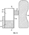
- Figures 9 and 10 show this possibility.
- One embodiment uses a proprietary formula of deodorants/antiperspirant and includes an embodiment in which it has been envisaged that the formula could be altered to enable enhanced drying with light curing technology. This would require an additional source of light at a particular frequency to dry the formula. This light source would be built into the device and could be combined with the moving air for further improvement in drying.
- the use of an existing third party formula would work very well with the current embodiment as long as the vessel holding the antiperspirant/deodorant was the same shape and design.
- an air movement/delivery mechanism 34 is located in an enclosure 28 with the vessel 26 containing the deodorant /antiperspirant.
- a removable cap for the enclosure is also shown on the
- the applicator head 25 is on top of the vessel 26 at a top end of the enclosure.
- the air delivery mechanism 34 draws air from one or more openings in the side of the vessel and delivers the air through an air outlet 30 on the bottom of the vessel. This requires turning the vessel over after applying the deodorant /antiperspirant to accelerate the drying of the deodorant /antiperspirant.
- the device can also be configured such that the air is directed toward the top of the applicator head 25 in the enclosure.
- this application device can be designed for the application of other products such as lotions, creams and gels utilized for other purposes beyond antiperspirants and deodorants.
- the feature of removable, exchangeable, replaceable, or refillable vessels as well as attachment to existing device for applying a substance to a surface can be utilized.
Landscapes
- Cosmetics (AREA)
- Drying Of Solid Materials (AREA)
- Application Of Or Painting With Fluid Materials (AREA)
Description
- Antiperspirants and deodorants are common everyday consumables that have been sold for many years and come in several common forms of delivery including aerosol sprays sold in cans, liquids in rollerball, solid stick and gel form. This is not an exhaustive list as other less popular forms exist.
- Advancements which are beneficial to the consumer are largely focused on the chemical formula that is applied on to the skin. This is mostly focused on how effective these products are at stopping perspiration or masking it. There are various formulas available ranging from normal strength formula up to clinical grade formula all aimed at consumers with problem perspiration. The products are normally associated with claims of protecting against perspiration for a given period of time, usually 24 and 48 hours.
- Other advancements are to the chemical formula are focused on eliminating/reducing the staining of clothes which is often associated with antiperspirants and less so deodorants. Antiperspirants contain an active ingredient that is used to block the sweat ducts and prevent perspiration. There are different types of active ingredient but most are Aluminum salt based like Aluminum Chloride.
- The active ingredients combined with electrolytes in sweat are acidic and it's the acidic nature that stains clothing especially when further reaction with washing detergent takes place. Health concerns associated with ingesting aluminum salts and the potential effects have led to other chemical advancements for alternatives to aluminum.
- The one feature that has been short of advancement is that of the chemical formula drying and bonding to the skin. This is somewhat difficult from a chemical perspective because the product is applied to a sensitive part of the body and solutions that would easily improve drying such as an alcohol based formula would cause other problems for the user like skin irritation. Improved drying time has been addressed by the delivery mechanism but this falls a long way short of solving the problem of lengthy drying times. Features of the 4 most common forms are as follows: Aerosol - very common delivery method that is mainly used in Europe. Aerosol delivery has the benefit of delivering a very thin layer of product and is best associated with quick drying times. Consumers however have less control over the accuracy of delivery due to the nature of a fine mist and also it can be unpleasant when sprayed in confined spaces. Consumer complaints can be fears on inhaling the gas as well as important environmental concerns. Modern aerosols are CFC free but still use other propellants like Propone and Butane, which are classed as VOC's (volatile organic compounds). Different countries have various rules and treatments for these aerosol VOC's with some making it very difficult for manufacturers to offer this format.
- Solid Stick - a method developed to address some concerns with drying times. The chemical formula comes in a solid format by the addition of waxes. Although this product when rubbed onto the skin may initially feel drier than a liquid, consumers are faced with other shortfalls. Immediate staining of clothes, especially dark garments is very common. The waxes that make the solid form can cause the formula to coagulate together and be difficult to remove even with soaps.
- Gel form - A more recent development to improve other product shortfalls. Gels are typically clear so don't give immediate staining, although their active ingredient when combined with sweat will cause staining of clothes. A gel dries quicker than a liquid since it is already in a less liquid form. Despite this, the drying times can be high with 5-10 minutes not uncommon. Delivery mechanisms of gels are typically crude with a form of pressure (plunger) forcing the gel through holes onto an applicator.
- Rollerball - This form is most associated with the liquid form of formula. The rollerball is good for keeping the formula airtight and to a degree allows for quite a controlled amount of delivery of formula. Liquid antiperspirant is often reviewed as the most effective. Whilst effectiveness is actually associated with the percentage of the active aluminum (or other) ingredient that makes up the formula because the delivery is a liquid (much like the gel forms) the consumer can perhaps apply this more carefully. Liquid antiperspirants and deodorants delivered in this method still have high drying times, where 5-10 minutes is not uncommon.
- Packaging is an environmental concern for many consumers. As antiperspirants and deodorants are mostly disposable items with a high degree of plastics and metals (for aerosols) the safe disposal of these packages is an environmental concern.
- Manufacturers of antiperspirants and deodorants are trending towards solutions with less packaging.
- Document
EP2090370 discloses a device for spraying a cosmetic or dermatological composition, comprising: an ultrasound or electrostatic spray head; an airflow generator for creating a stream of air for entraining a spray of composition particles atomized by the spray head; and a conditioning device for modifying the temperature of the outgoing stream of air, the conditioning device being placed upstream from the airflow generator. - A device according to
claim 1 and a method according toclaim 15 for shortening the drying time of a moist substance such as a liquid, cream or gel is disclosed. The device contains the substance to be applied along with the mechanism for shortening the drying time. Or the device can be designed to attach to an existing vessel containing the moist substance to be applied. - In one embodiment the device combines a system to move air with an applicator for antiperspirant or deodorant. The device results in vastly improved drying time of the substance or formula on the skin. The device can be part mechanical and part electrically powered by means of a power supply, in this case a battery.
- In one embodiment the device uses well-known principles of fluid dynamics to create an airflow that moves across the surface of the skin and reduces the drying time of liquids and gel forms of antiperspirant and deodorant. In order to achieve the right direction of airflow the device employs a coanda surface. A coanda surface is a surface close to the exit of the airflow, in this case the air outlet collar, where airflow demonstrates the coanda effect. The air essentially hugs the contours of the coanda surface as it moves across it.
- Fluid dynamic principles are also used to improve the volume of air moved by the device utilizing a multiplier effect. This is achieved by way of the Venturi-Ejector principle. Airflow is deliberately manipulated to increase velocity and decrease pressure, which has the effect of drawing air from the space surrounding the device into the main enclosure / housing and entraining the air.
- The device is intended to be highly portable and small. A design described in detail below is similar in size to many disposable antiperspirants / deodorant containers sold today and is only limited by parts currently available.
- This device significantly reduces the drying time of the antiperspirants and deodorant. And when the device is combined with a proprietary formula it vastly improves the drying time of any typical gel or liquid antiperspirant or deodorant.
- The device features exchangeable vessels of antiperspirant or deodorant formula that will be disposed of or recycled once the formula is exhausted. The vessels can also be designed to be refilled. This exchangeable or refillable feature will allow for less wasteful packaging but also empower consumer choice as to the scent and formula strength including chemical active ingredient versus more natural formula. There is less packaging used because the mechanism for delivery of the formula is a permanent feature of the invention and not disposed of as with current antiperspirants and deodorants.
- Other embodiments include: drawing the air away from the surface on which the substance is applied; drawing air away and simultaneously move air across the surface; drawing air from the sides of the device with air movement / delivery mechanism and air outlet on the bottom of the device; using a light source to quicken the drying time of the substance; and using a heat source to quicken the drying time of the substance.
-
-
Figure 1 - Front view of the one embodiment showingapplicator head 1,air outlet collar 3, power/control button(s) 6,enclosure 11,air intake 14 and applicator head lid/cover 21 -
Figure 2 - Rear view of the embodiment showingapplicator head 1,air outlet collar 3,ejector inlets 4,applicator control 5, ,enclosure 11,air intake 14, applicator head and lid/cover 21 and chargingport 22. -
Figure 3 - Side view of the embodiment showing applicator head andlid 1,air outlet collar 3,ejector inlets 4,applicator control 5, power/control button(s) 6,enclosure 11,air intake 14 and applicator head lid/cover 21. -
Figure 4 - Cross section ofFigure 3 showing applicator head 1, antiperspirant/deodorant vessel orcapsule 2,air outlet collar 3, mechanism for delivery of formula toapplicator head 7,air channel throat 8,Control module 9,power source 10,enclosure 11,air channels 12,fan unit 13,air intake 14, enclosurelower section 15, enclosuremiddle section 16, enclosureupper section 17,core section 18 andstructural supports 23. -
Figure 5 - Cross section ofFigure 1 showing applicator head 1, antiperspirant/deodorant vessel orcapsule 2,air outlet collar 3, mechanism for delivery of formula toapplicator head 7,air channel throat 8,Control module 9,power source 10,enclosure 11,air channels 12,fan unit 13,air intake 14, enclosurelower section 15, enclosuremiddle section 16, enclosureupper section 17,core section 18, chargingport 22 andstructural supports 23. -
Figure 6 - Simplified cross section side view illustrating direction of airflow and the ejector system to multiply the air. In addition this figure depicts the aerodynamic Coanda effect created byCoanda surface 19 and entrainedair 20. -
Figure 7 - Front view of another embodiment showing anapplicator head 25,air intake 27,enclosure 28, control functions 29,air outlet 30, andinner structure 35. -
Figure 8 is a cross section ofFigure 7 showing additional components of this embodiment antiperspirant /deodorant vessel 26,control module 31,air channel 32, combined power andfan module 37, andair intake channel 38. -
Figure 9 is a front view of another embodiment showingapplicator head 25, antiperspirant /deodorant vessel 26,enclosure 28, control functions 29,air outlet 30, and mounting clips 36. -
Figure 10 is a cross section ofFigure 9 showing additional components combined power andcontrol module 33, andfan module 34. -
Figure 11 depicts another embodiment showingapplicator head 25,air intake 27,enclosure 28, control functions 29, andair outlet 30. -
Figure 12 is a cross section ofFigure 11 showing additional components antiperspirant /deodorant vessel 26,air channel 32, power andcontrol module 33, andfan module 34, and mechanism for delivery of formula toapplicator head 39. -
Figure 13 depicts another embodiment. -
Figure 14 depicts a cross section of the embodiment inFigure 13 . -
- 1.
- Applicator head
- 2.
- Antiperspirant/Deodorant vessel or capsule
- 3.
- Air outlet collar
- 4.
- Ejector inlet
- 5.
- Applicator control
- 6.
- Power/Control button(s)
- 7.
- Mechanism for delivery of formula to applicator head
- 8.
- Air channel throat
- 9.
- Control module
- 10.
- Power source
- 11.
- Enclosure
- 12.
- Air channels
- 13.
- Fan Unit
- 14.
- Air intake
- 15.
- Enclosure lower section
- 16.
- Enclosure middle section
- 17.
- Enclosure Upper section
- 18.
- Core section
- 19.
- Coanda surface
- 20.
- Entrained air
- 21.
- Applicator head cover/lid
- 22.
- Recharging port
- 23.
- Structural Supports
-
- 25
- Applicator Head
- 26
- Antiperspirant/Deodorant vessel or capsule
- 27
- Air Intake
- 28
- Enclosure
- 29
- Control functions
- 30
- Air outlet
- 31
- Control module
- 32
- Air Channels
- 33
- Combined Power & Control module
- 34
- Fan module
- 35
- Inner structure
- 36
- Mounting clips
- 37
- Combined power & Fan module
- 38
- Air intake channel
- 39.
- Mechanism for delivery of formula to applicator head
- Carrier - The chemical formula that actually carries the antiperspirant or deodorant active ingredient. It is this carrier that needs to evaporate on the skin for it to feel dry.
- Multiple embodiments are disclosed for a device for applying a substance to a surface and accelerating the drying of the substance. The device includes a vessel containing the substance to be applied or can be attached to a vessel. The vessel can be a vessel created by others or a vessel included in the design of the device. An applicator head is mounted or attached on a top of the vessel. The device includes an enclosure or housing and can be mounted with the vessel either by enclosing the vessel or attaching to the vessel. A mechanism to create and deliver a form of energy is located in the housing and directed toward the applicator head. Many forms of energy are usable including gas or air movement, heat, light, or any combination of those energy forms. The power source for the mechanism is chosen based on power required for the actual mechanism. Examples of power sources are an electric power source or an air or other gas source. If the power source is located within the device a battery can be used or a pressurized container of gas/air. A control module including control devices as warranted are included in or on the housing. In other embodiments the power source is external to the outer wall of the enclosure for the device. When the power source is located external to the device a power cord or hose is extended from i the enclosure to the power source. The power source can even be a user blowing into a hose connected to the enclosure..
- One embodiment is shown on
Figures 1-6 .Figure 4 shows the cross section front view andFigure 2 the rear view. Theapplicator control 5 is moved by the user and a mechanism for delivery of the formula to theapplicator head 7 translates movement into an upwards movement of a plunger or equivalent in order to cause pressure on the antiperspirant or deodorant gel in the antiperspirant/deodorant vessel orcapsule 2. - The resulting pressure moves the gel towards the
applicator head 1 and onto the user by way of one or more opening such as small apertures in the surface of theapplicator head 1. Theapplicator control 5 may be a button, wheel, sliding type switch or other means for the user interacting with the device. Possible mechanisms for delivery of the formula to theapplicator head 7 include a screw type mechanism, a jacking or racking mechanism, a sliding push mechanism, a spring or other means known to those skilled in delivery mechanisms. Theapplicator head 1 is used to apply the antiperspirant or deodorant to the body with the shape of theapplicator head 1 helping to spread the product evenly onto the surface of the skin. It is envisaged that theapplicator head 1 will be attached to the antiperspirant/deodorant vessel orcapsule 2 to form one unit although this could also be two distinct replaceable pieces. - It is envisaged that an alternative applicator surface could be employed such as a standard rollerball attached to a disposable or refillable vessel. The current design makes great use of the shape of the applicator head in order to create a coanda surface to help improve performance. Any alternative applicator surface would come with a different performance. An alternative applicator such as a rollerball could also eliminate the need for the mechanism for delivery of the formula to the applicator head.
-
Figure 1 shows components of a control circuit for the fan including power/control button(s) 6.Figure 4 shows acontrol module 9, apower source 10 and afan unit 13. Electrical connections between the devices in the control module utilize wiring or other types of electrically conducting connectors. The power/control button(s) 6 can be used to control the on/off and regulate the speed of airflow. The power/control button(s) 6 activates anelectric fan unit 13. In one embodiment thefan unit 13 is a Vein Axial Flow fan using DC power. The device can be configured to utilize AC power. It is also envisaged that another embodiment may be designed to allow connection to an external power source as an alternative to thePower Source 10. Other embodiments utilize different air movement devices such as a bladeless device. In another embodiment the air movement / delivery mechanism is compressed gas from a pressurized gas container, in which case an electrical control circuit may not be needed. In another embodiment a tube / hose can be provided to allow the user to blow air which is directed to the area of application of the substance to the user's surface. - The power/control button(s) 6 are a means for the user to activate and control the device. In other embodiments the power/control button(s) 6 utilize capacitive or resistive touch sensor as a means of interaction. The power/control button(s) 6 may also use acoustic touch sensor.
- The
control module 9 controls the device and can be designed to allow programming for control of the device. Thecontrol module 9 may control charging of the power source to increase power source life and make charging a safe process. It is also used to control the on/off and speed of the device. Thecontrol module 9 also can be programmed to control a visual alert utilizing one or more light emitting diode (LED) or some form of electronic display such as a liquid crystal display (LCD), organic light -emitting diode display (OLED), or an active-matrix organic light-emitting diode display (AMOLED). The visual alert can indicate information such as speed of the device air delivery, power source charging indicator, reserve of power source and the volume of deodorant/antiperspirant left in the antiperspirant/deodorant vessel orcapsule 2. In one embodiment the display indicates how dry the deodorant/antiperspirant is on the skin. It is also envisaged that an audible alert could be used so the user could be aware for example that the power source energy is low and needs charging, that the deodorant is dry, that the device is being charged, or that the antiperspirant/deodorant vessel orcapsule 2 is almost empty. To activate all of the alerts appropriate well known sensors are required in the control circuit such as voltage, humidity, pressure, etc.Figure 3 shows a chargingport 22, which is connected to thecontrol module 9 by means of wires or other electrical conducting material. - In one embodiment the enclosure has a
lower section 15 and bottom end, amiddle section 16, and anupper section 17 with a top end. Referring toFigure 4 thefan unit 13 once activated draws air from the surroundings by way of theair intake 14 located at the bottom end of thelower section 15. This air is moved through anair channel 12 between an inner wall of theenclosure 11 and thecore section 18 inside of theenclosure 11. Thecore section 18 houses thepower source 10,control module 9, a vessel containing the substance to be applied 26, amechanism 7 for delivery of formula toapplicator head 1, and appropriate electrical connections. An inward taper of theenclosure 11 creates a reduction in annular cross sectional area in theair channel 12 as the air advances toward theoutlet collar 3. This looks like a taper or pinch of the sidewalls. This results in an internal reduction in annular area for theair channel 12 at the point of theair channel throat 8. This reduction in annular area for the air to move through has the result of increasing air speed and decreasing the air pressure at the point of theair channel throat 8, caused by the conservation of energy principle. - After passing the
air channel throat 8 thechannel 12 features an outward taper or flare design allowing the fast moving air to expand. The faster moving air has lower pressure as it passes theejector inlets 4. The 1Venturi effect of the fast moving lower pressure air pulls in air from air surrounding theenclosure 11 through theejector inlets 4 and into thechannel 12.. This air becomes entrainedair 20 and exits at theair outlet collar 3 along with air that is driven through theair channel 12 by thefan unit 13. The result of the Venturi-Ejector principle is a multiplier effect of air moved. The volume of air that exits theair outlet collar 3 is greater than that which is moved by thefan unit 13. - The
air outlet collar 3 located in theupper section 17 and top end of theenclosure 11 is an aperture that surrounds theapplicator head 1 such that air is delivered around the entire perimeter of theapplicator head 1. The total surface area of theair outlet collar 3 is what determines the airspeed and pressure and will have an optimum efficient size for any given type of fan unit or other mechanism causing the movement of air in the main unit. Theair outlet collar 3 in one embodiment surrounds theapplicator head 1 like a collar but other embodiments utilize other designs such as a simple air flow hole or holes in varying shapes and sizes. - There are several variables to consider for maximizing the efficiency of the Venturi-Ejector. The first variable to consider is the amount of reduction in annular area at the
air channel throat 8. The greater the reduction of the area of the air channel at this point the faster will be the air speed and resulting pressure drop, however this is limited by the capability of the air movement mechanism being utilized. If afan unit 13 is utilized, the torque capability of thefan unit 13 must be considered. If the area is too small it will result in back pressure on thefan unit 13 which must be considered. The number ofejector inlets 4 can be varied as desired since the principle that is important is the surface area of inlet as a percentage of the annular area at theair channel throat 8. This is designed to have an efficient ratio to maximize airflow. The angle of theenclosure 11 design where it flares outward after theair channel throat 8 is typically between 10-15 degrees to maximize efficiency of entrained air. - Other embodiments feature different designs to multiply the air. A more traditional Venturi design could be used where the air attracted to the low-pressure zone takes place at a different location of the enclosure for instance closer to the
fan unit 13. The embodiment shown infigures 1 -6 utilizesejector inlets 4 that come after the pinch in the body to the direction of airflow. This is the Venturi-Ejector principle. Other fluid dynamics principles can be used to result in a similar effect to multiply air moved by entraining surrounding air. - Other embodiments may not use any principles to multiply or amplify the air; whilst this would be less efficient it would still improve drying compared to no air movement at all. Such an embodiment would just move air from an intake source through to an outlet with little or no manipulation or the source or air could just be a compressed gas canister that is moved through the device to an outlet. In such an embodiment employing a canister or vessel of compressed air it is also envisaged that a gas other than air could be used. Using a gas other than air could have other benefits that would enhance drying time further.
- With regards to drying the antiperspirant or deodorant more quickly it is important to first understand how convection works. Convection decreases localized humidity caused by the evaporation of the carrier in the air around the skin application area until equilibrium of humidity is reached between the skin and the air around it. Moving air means that equilibrium is not reached which would slow the rate of evaporation, as saturated air will not hold any more carrier molecules. By keeping the air above the area of skin application clear of carrier molecules a differential gradient facilitates effective evaporation and also prevents gaseous carrier to condense back into the liquid form on the skin. Air that is moved across the surface of the skin will result in quicker drying times that air aimed directly perpendicular to the skin surface.
- The device disclosed facilitates the application of antiperspirant or deodorant and drying as quickly as possible. The design has therefore been made such that the multiplied air that exits at the
air outlet collar 3 directs air movement across the skin to improve drying. Theapplicator head 1 is designed to create a coanda surface at the point of theair outlet collar 3. The arrows inFigure 6 depict the airflow. AlthoughFigure 6 depicts a side cross section, the coanda airflow takes place around the total circumference of theapplicator head 1. The resulting coanda airflow reduces the drying time of the carrier of the formula antiperspirant or deodorant as described above in the convection principle. It is perfectly possible that alternate embodiments would not use a coanda surface as whilst this improves drying it does add to the complication of design. - It is envisaged that other versions of the device could feature moving air that is heated by some method to improve the drying time further. It is important to note that in this current embodiment the air moved through the device will be heated by the presence of the
control module 9,power source 10, and fan unit which generate heat when the device is activated. The heat generated by these components is minimal but, it is a secondary effect of operation. Deliberate heating can be added in several ways such as a traditional simple heating element controlled directly by a switch or by thecontrol module 9. - The Venturi-Ejector and Coanda Surface have the combined effect of making the air moved by the
fan unit 13 feel softer on the skin but result in a increased volume of air moving in a direction to greatly reduce the drying time. It has also been envisaged that the single use or combined use of a Vortex of air could be used to achieve similar results. - Other embodiments include sensors to monitor parameters such as pressure, voltage, current, air flow, and humidity. These sensors can be used for indication or operational control by the
control module 9. - It is envisaged that another embodiment of the invention would also use a means of moving air but it envisaged that the movement of air could be reversed such that the air intake area is close to the surface of the skin. This would achieve improved drying of but in effect using suction of saturated air away from the surface of the skin. This could be achieved with or without fluid dynamic principals such as the Ejector or Venturi that multiply the air moved through the device.
Figures 7 &8 depict an alternative embodiment to demonstrate this possibility. Air is drawn away from the surface viaair intake 27 and then pushed back to the surface via theair outlet 30. In this case the air is both withdrawn and moved back to the same surface. Air could also be just withdrawn via theair intake 27 and theair outlet 30 could be aimed away from the surface to be dried. Such alternative embodiments allow for different configurations of the components of the device in order to facilitate different shapes for the design of the device. - The embodiment shown in
Figures 1 through 5 uses a vertical stack of components: theapplicator head 1, antiperspirant/deodorant vessel orcapsule 2, mechanism for delivery of formula toapplicator head 7,air channel throat 8,control module 9,power source 10,air channels 12,fan unit 13,air intake 14. It is envisaged that these components could be organized in a different configuration. For example thepower source 10 andcontrol module 9, could be positioned around thefan unit 13. Theair intake 14 could actually be located on theenclosure 11 in a different location. Whilst these different combinations would not necessarily change the performance of the invention but they would allow for different designs in terms of shapes and sizes. The antiperspirant/deodorant capsule 2 could be positioned outside of theair channels 12 such that it sits parallel to the air channel or even perpendicular or at some angle in between.Figures 11 and12 show such a possible embodiment. These are intended an example of the possible configurations for another embodiment of the device. It has also been envisaged that for the current embodiment and the further versions discussed any of these could be used with a less sophisticated design that would just use an air movement device without the use of fluid dynamic principals to multiply or amplify the air moved. This would be less efficient that the current embodiment but would still lead to improved drying. - A less sophisticated design that could achieve a similar effect of improved drying would be a further embodiment where the air movement device and control of such could be combined with existing third party deodorants/antiperspirants. Such an embodiment could take the form of a clip on device to existing popular deodorants/antiperspirants.
Figures 9 and10 show this possibility. - One embodiment uses a proprietary formula of deodorants/antiperspirant and includes an embodiment in which it has been envisaged that the formula could be altered to enable enhanced drying with light curing technology. This would require an additional source of light at a particular frequency to dry the formula. This light source would be built into the device and could be combined with the moving air for further improvement in drying. The use of an existing third party formula would work very well with the current embodiment as long as the vessel holding the antiperspirant/deodorant was the same shape and design.
- In another embodiment shown on
Figures 13 and14 an air movement/delivery mechanism 34 is located in anenclosure 28 with thevessel 26 containing the deodorant /antiperspirant. A removable cap for the enclosure is also shown on the - Figures. The
applicator head 25 is on top of thevessel 26 at a top end of the enclosure. Theair delivery mechanism 34 draws air from one or more openings in the side of the vessel and delivers the air through anair outlet 30 on the bottom of the vessel. This requires turning the vessel over after applying the deodorant /antiperspirant to accelerate the drying of the deodorant /antiperspirant. The device can also be configured such that the air is directed toward the top of theapplicator head 25 in the enclosure. - In other embodiments this application device can be designed for the application of other products such as lotions, creams and gels utilized for other purposes beyond antiperspirants and deodorants. In all these other applications, the feature of removable, exchangeable, replaceable, or refillable vessels as well as attachment to existing device for applying a substance to a surface can be utilized.
- The above is a detailed description of particular embodiments of the invention. It is recognized that departures from the disclosed embodiments may be made within the scope of the invention and that obvious modifications will occur to a person skilled in the art. Those of skill in the art should, in light of the present disclosure, appreciate that many changes can be made in the specific embodiments which are disclosed herein and still obtain a like or similar result without departing from the scope of the invention. All of the embodiments disclosed and claimed herein can be made and executed without undue experimentation in light of the present disclosure.
Claims (15)
- A device for applying a substance to a surface comprising:an enclosure (11) with an outer wall, an upper section (17), a middle section (16), and a lower section (15); an air intake (14) located in the lower section of the enclosure;an air outlet (30) located in the upper section of the enclosure;a core section (18) in the enclosure includes an air movement mechanism, a vessel containing the substance to be applied, a substance movement mechanism for forcing the substance to be applied to a top end of the vessel, and a control module to control the air movement mechanism and the substance movement mechanism;at least one air channel (12) created between the enclosure and the core section; andan opening in the top end of the vessel, CHARACTERISED IN THAT,the enclosure comprises an inward taper toward the core section, which creates a reduction in an annular cross-sectional area in the air channel as the air advances toward the outlet.
- A device according to Claim 1 further comprising an applicator head (1), which is designed to create a coanda effect, is located on the top of the vessel in the core section.
- A device according to Claim 1 further comprising
an air channel throat (8) created in the air channel by the inward taper in the enclosure toward the core section; and
at least one ejector inlet (4) located on the enclosure wherein the ejector inlet is located between the air outlet in the enclosure and the air channel throat. - A device according to Claim 3 further comprising
an applicator head which is designed to create a coanda effect is located on the top of the vessel in the core section. - A device for applying a substance to a surface according to Claim 4 wherein the air movement mechanism is a fan which is powered by a power source located in the core section.
- A device for applying a substance to a surface according to Claim 4 wherein the air movement mechanism is a fan (13) which is powered by a power source (10) located external to the device.
- A device for applying a substance to a surface according to Claim 4 wherein the substance to be applied is a lotion and the surface is a person's skin.
- A device for applying a substance to a surface according to Claim 4 wherein the vessel is designed to be removable.
- A device for applying a substance to a surface according to Claim 4 wherein the taper in the enclosure is a taper inward in the middle section which then expands outward in the upper section.
- A device for applying a substance to a surface according to Claim 4 further comprising a heat generating mechanism to create and deliver heat, and power source and controls for the heat generating mechanism.
- A device for applying a substance to a surface according to Claim 4 wherein the air movement mechanism is a pressurized gas container.
- A device for applying a substance to a surface according to Claim 4 wherein the taper in the enclosure is a taper inward in the lower section which then expands outward in the upper section.
- A device for applying a substance to a surface according to Claim 4 wherein the mechanism for forcing the substance to be applied to the top end of the vessel is a screw type mechanism.
- A device for applying a substance to a surface according to Claim 4 wherein the mechanism for forcing the substance to be applied to the top of the vessel, is a jacking mechanism.
- A method for applying a substance to a surface using the device according to any preceding claim, the method comprising:forcing substance to the top end of the vessel to push the substance onto the applicator head (1) using the control device for the substance movementmechanism;pressing the applicator head against the surface;creating air movement using the control device for the air movement mechanism.
Applications Claiming Priority (2)
| Application Number | Priority Date | Filing Date | Title |
|---|---|---|---|
| US201461983205P | 2014-04-23 | 2014-04-23 | |
| PCT/GB2015/051203 WO2015162430A2 (en) | 2014-04-23 | 2015-04-23 | Product application device |
Publications (2)
| Publication Number | Publication Date |
|---|---|
| EP3133956A2 EP3133956A2 (en) | 2017-03-01 |
| EP3133956B1 true EP3133956B1 (en) | 2018-02-07 |
Family
ID=57528753
Family Applications (1)
| Application Number | Title | Priority Date | Filing Date |
|---|---|---|---|
| EP15726661.0A Active EP3133956B1 (en) | 2014-04-23 | 2015-04-23 | Product application device |
Country Status (8)
| Country | Link |
|---|---|
| US (3) | US9668563B2 (en) |
| EP (1) | EP3133956B1 (en) |
| CN (1) | CN106231952B (en) |
| AU (1) | AU2015250636B2 (en) |
| BR (1) | BR112016024583B1 (en) |
| CA (1) | CA2945932C (en) |
| NZ (1) | NZ726571A (en) |
| WO (1) | WO2015162430A2 (en) |
Families Citing this family (11)
| Publication number | Priority date | Publication date | Assignee | Title |
|---|---|---|---|---|
| AU2016290895B2 (en) * | 2015-07-06 | 2021-05-06 | Mitchell Terrace Pty. Ltd. | Device for applying a product |
| US10398527B2 (en) * | 2016-08-11 | 2019-09-03 | Terumo Cardiovascular Systems Corporation | Surgical tissue marking device with dryer |
| USD835520S1 (en) * | 2016-09-01 | 2018-12-11 | Modus S.A.R.L. | Deodorant stick |
| USD791615S1 (en) * | 2016-10-05 | 2017-07-11 | David M Stravitz | Dispenser |
| US11382400B2 (en) | 2018-08-10 | 2022-07-12 | Go Products Co. | Material applicator |
| CN110203559A (en) * | 2019-06-26 | 2019-09-06 | 广东美妆优品科技有限责任公司 | A kind of aerosol bottle |
| US20210244629A1 (en) * | 2020-02-10 | 2021-08-12 | Kenneth Anderson | Multi-layer deodorant applicator sticks having multiple sensory characteristics |
| CN112275703A (en) * | 2020-09-30 | 2021-01-29 | 南京华易泰电子科技有限公司 | Water jet cutter structure utilizing coanda effect |
| US20240315438A1 (en) * | 2023-03-22 | 2024-09-26 | Cassidy Lynn Stahl | Thermal conductive makeup application apparatus |
| JP7569956B1 (en) | 2024-05-13 | 2024-10-18 | Tbcグループ株式会社 | Treatment lotion application device and lotion application method |
| USD1133931S1 (en) | 2025-01-15 | 2026-07-14 | Athena Club Holdings, Inc. | Deodorant container |
Family Cites Families (11)
| Publication number | Priority date | Publication date | Assignee | Title |
|---|---|---|---|---|
| DE4326108A1 (en) * | 1993-08-04 | 1995-02-09 | Alfred Von Schuckmann | Dispenser for dispensing preferably solid masses |
| JPH11169231A (en) * | 1997-12-16 | 1999-06-29 | Ryuichi Utsuki | Cosmetic method, cosmetic device used for the method, and cosmetic transfer film |
| GB2354711B (en) * | 1999-08-10 | 2003-10-29 | Johnson & Son Inc S C | Dual function dispenser |
| US6695510B1 (en) * | 2000-05-31 | 2004-02-24 | Wyeth | Multi-composition stick product and a process and system for manufacturing the same |
| US8192100B2 (en) | 2006-11-06 | 2012-06-05 | Blistex Inc. | Fluid applicator device and method of using same |
| FR2927237B1 (en) | 2008-02-13 | 2011-12-23 | Oreal | DEVICE FOR SPRAYING A COSMETIC PRODUCT WITH HOT OR COLD AIR BLOWING |
| DE102009014976B3 (en) * | 2009-03-30 | 2010-06-02 | Jutta Munz | Applicator device for applying e.g. cream on eye portion of human body, has activator device provided in upper housing part, and producing heat or coldness that is transmitted to substance contained in substance chamber |
| US8393813B2 (en) * | 2009-12-23 | 2013-03-12 | The Dial Corporation | Personal care product dispenser systems |
| CN202722921U (en) * | 2012-06-21 | 2013-02-13 | 上海理工大学 | Nail polish bottle with air blowing function |
| US9210985B2 (en) * | 2013-06-19 | 2015-12-15 | Gilad Arwatz | Electromechanical system for dispensing deodorant / antiperspirant |
| WO2016033202A1 (en) * | 2014-08-26 | 2016-03-03 | Freshceuticals, Inc. | Consumer products applicator and related methods |
-
2015
- 2015-04-23 BR BR112016024583-0A patent/BR112016024583B1/en not_active IP Right Cessation
- 2015-04-23 NZ NZ726571A patent/NZ726571A/en not_active IP Right Cessation
- 2015-04-23 CA CA2945932A patent/CA2945932C/en active Active
- 2015-04-23 US US14/693,961 patent/US9668563B2/en active Active
- 2015-04-23 AU AU2015250636A patent/AU2015250636B2/en not_active Ceased
- 2015-04-23 EP EP15726661.0A patent/EP3133956B1/en active Active
- 2015-04-23 CN CN201580020655.8A patent/CN106231952B/en not_active Expired - Fee Related
- 2015-04-23 WO PCT/GB2015/051203 patent/WO2015162430A2/en not_active Ceased
-
2017
- 2017-03-28 US US15/471,038 patent/US10188190B2/en active Active
- 2017-04-28 US US15/581,381 patent/US10092080B2/en active Active
Also Published As
| Publication number | Publication date |
|---|---|
| US10188190B2 (en) | 2019-01-29 |
| BR112016024583A2 (en) | 2020-06-30 |
| US20170196338A1 (en) | 2017-07-13 |
| AU2015250636B2 (en) | 2020-03-12 |
| US20150305473A1 (en) | 2015-10-29 |
| US20170245619A1 (en) | 2017-08-31 |
| CA2945932C (en) | 2020-07-07 |
| EP3133956A2 (en) | 2017-03-01 |
| NZ726571A (en) | 2022-07-01 |
| US10092080B2 (en) | 2018-10-09 |
| WO2015162430A3 (en) | 2016-03-24 |
| CN106231952B (en) | 2019-10-01 |
| WO2015162430A2 (en) | 2015-10-29 |
| US9668563B2 (en) | 2017-06-06 |
| CN106231952A (en) | 2016-12-14 |
| CA2945932A1 (en) | 2015-10-29 |
| BR112016024583B1 (en) | 2022-05-31 |
| AU2015250636A1 (en) | 2016-12-08 |
Similar Documents
| Publication | Publication Date | Title |
|---|---|---|
| US10092080B2 (en) | Deodorant product application device | |
| US9267735B2 (en) | Dryer | |
| CN100577302C (en) | Apparatus for atomizing products, especially perfumes | |
| US8746586B2 (en) | Device for spraying a cosmetic composition while blowing hot or cold air | |
| JP3857136B2 (en) | Handheld electrostatic spray device | |
| US20180289076A1 (en) | Atomizing assembly for use in an aerosol-generating system | |
| WO2017036426A3 (en) | Atomisation device | |
| EP1639910A3 (en) | Electrostatic atomizing hairdryer and electrostatic atomizer | |
| US20220175107A1 (en) | Atomization Device for a Hair Dryer | |
| US20050211797A1 (en) | Fluid product dispenser | |
| JP4573778B2 (en) | Blower | |
| JP6148393B1 (en) | Clothes cooling system | |
| JP3184382U (en) | Charged atomizer | |
| US20050212879A1 (en) | Replaceable electrostatically sprayable material reservoir for use with a electrostatic spraying device | |
| KR20240027652A (en) | Device for generating aerosol | |
| GB2322554A (en) | Aroma emitting apparatus | |
| KR102509999B1 (en) | Non-Contact Cosmetics Fine Spraying Device | |
| JP4676342B2 (en) | Electrostatic atomizer and blower | |
| CN217117505U (en) | Battery pack and electronic atomization device | |
| CN224207185U (en) | High-speed atomizing device | |
| WO2024137881A1 (en) | Vaporizer device with hybrid heater | |
| CN208894447U (en) | Novel atomized machine | |
| KR20220111901A (en) | wireless fog machine | |
| KR20210071758A (en) | fragrant hangers | |
| TWM540693U (en) | Handheld liquid atomization device |
Legal Events
| Date | Code | Title | Description |
|---|---|---|---|
| STAA | Information on the status of an ep patent application or granted ep patent |
Free format text: STATUS: THE INTERNATIONAL PUBLICATION HAS BEEN MADE |
|
| PUAI | Public reference made under article 153(3) epc to a published international application that has entered the european phase |
Free format text: ORIGINAL CODE: 0009012 |
|
| STAA | Information on the status of an ep patent application or granted ep patent |
Free format text: STATUS: REQUEST FOR EXAMINATION WAS MADE |
|
| 17P | Request for examination filed |
Effective date: 20161005 |
|
| AK | Designated contracting states |
Kind code of ref document: A2 Designated state(s): AL AT BE BG CH CY CZ DE DK EE ES FI FR GB GR HR HU IE IS IT LI LT LU LV MC MK MT NL NO PL PT RO RS SE SI SK SM TR |
|
| AX | Request for extension of the european patent |
Extension state: BA ME |
|
| DAV | Request for validation of the european patent (deleted) | ||
| DAX | Request for extension of the european patent (deleted) | ||
| GRAP | Despatch of communication of intention to grant a patent |
Free format text: ORIGINAL CODE: EPIDOSNIGR1 |
|
| STAA | Information on the status of an ep patent application or granted ep patent |
Free format text: STATUS: GRANT OF PATENT IS INTENDED |
|
| INTG | Intention to grant announced |
Effective date: 20170919 |
|
| GRAS | Grant fee paid |
Free format text: ORIGINAL CODE: EPIDOSNIGR3 |
|
| GRAA | (expected) grant |
Free format text: ORIGINAL CODE: 0009210 |
|
| STAA | Information on the status of an ep patent application or granted ep patent |
Free format text: STATUS: THE PATENT HAS BEEN GRANTED |
|
| AK | Designated contracting states |
Kind code of ref document: B1 Designated state(s): AL AT BE BG CH CY CZ DE DK EE ES FI FR GB GR HR HU IE IS IT LI LT LU LV MC MK MT NL NO PL PT RO RS SE SI SK SM TR |
|
| REG | Reference to a national code |
Ref country code: GB Ref legal event code: FG4D |
|
| REG | Reference to a national code |
Ref country code: AT Ref legal event code: REF Ref document number: 968462 Country of ref document: AT Kind code of ref document: T Effective date: 20180215 Ref country code: CH Ref legal event code: EP |
|
| REG | Reference to a national code |
Ref country code: IE Ref legal event code: FG4D |
|
| REG | Reference to a national code |
Ref country code: DE Ref legal event code: R096 Ref document number: 602015007951 Country of ref document: DE |
|
| REG | Reference to a national code |
Ref country code: FR Ref legal event code: PLFP Year of fee payment: 4 |
|
| REG | Reference to a national code |
Ref country code: NL Ref legal event code: MP Effective date: 20180207 |
|
| REG | Reference to a national code |
Ref country code: AT Ref legal event code: MK05 Ref document number: 968462 Country of ref document: AT Kind code of ref document: T Effective date: 20180207 |
|
| PG25 | Lapsed in a contracting state [announced via postgrant information from national office to epo] |
Ref country code: FI Free format text: LAPSE BECAUSE OF FAILURE TO SUBMIT A TRANSLATION OF THE DESCRIPTION OR TO PAY THE FEE WITHIN THE PRESCRIBED TIME-LIMIT Effective date: 20180207 Ref country code: LT Free format text: LAPSE BECAUSE OF FAILURE TO SUBMIT A TRANSLATION OF THE DESCRIPTION OR TO PAY THE FEE WITHIN THE PRESCRIBED TIME-LIMIT Effective date: 20180207 Ref country code: NL Free format text: LAPSE BECAUSE OF FAILURE TO SUBMIT A TRANSLATION OF THE DESCRIPTION OR TO PAY THE FEE WITHIN THE PRESCRIBED TIME-LIMIT Effective date: 20180207 Ref country code: CY Free format text: LAPSE BECAUSE OF FAILURE TO SUBMIT A TRANSLATION OF THE DESCRIPTION OR TO PAY THE FEE WITHIN THE PRESCRIBED TIME-LIMIT Effective date: 20180207 Ref country code: ES Free format text: LAPSE BECAUSE OF FAILURE TO SUBMIT A TRANSLATION OF THE DESCRIPTION OR TO PAY THE FEE WITHIN THE PRESCRIBED TIME-LIMIT Effective date: 20180207 Ref country code: HR Free format text: LAPSE BECAUSE OF FAILURE TO SUBMIT A TRANSLATION OF THE DESCRIPTION OR TO PAY THE FEE WITHIN THE PRESCRIBED TIME-LIMIT Effective date: 20180207 Ref country code: NO Free format text: LAPSE BECAUSE OF FAILURE TO SUBMIT A TRANSLATION OF THE DESCRIPTION OR TO PAY THE FEE WITHIN THE PRESCRIBED TIME-LIMIT Effective date: 20180507 |
|
| PG25 | Lapsed in a contracting state [announced via postgrant information from national office to epo] |
Ref country code: GR Free format text: LAPSE BECAUSE OF FAILURE TO SUBMIT A TRANSLATION OF THE DESCRIPTION OR TO PAY THE FEE WITHIN THE PRESCRIBED TIME-LIMIT Effective date: 20180508 Ref country code: RS Free format text: LAPSE BECAUSE OF FAILURE TO SUBMIT A TRANSLATION OF THE DESCRIPTION OR TO PAY THE FEE WITHIN THE PRESCRIBED TIME-LIMIT Effective date: 20180207 Ref country code: PL Free format text: LAPSE BECAUSE OF FAILURE TO SUBMIT A TRANSLATION OF THE DESCRIPTION OR TO PAY THE FEE WITHIN THE PRESCRIBED TIME-LIMIT Effective date: 20180207 Ref country code: BG Free format text: LAPSE BECAUSE OF FAILURE TO SUBMIT A TRANSLATION OF THE DESCRIPTION OR TO PAY THE FEE WITHIN THE PRESCRIBED TIME-LIMIT Effective date: 20180507 Ref country code: AT Free format text: LAPSE BECAUSE OF FAILURE TO SUBMIT A TRANSLATION OF THE DESCRIPTION OR TO PAY THE FEE WITHIN THE PRESCRIBED TIME-LIMIT Effective date: 20180207 Ref country code: IS Free format text: LAPSE BECAUSE OF FAILURE TO SUBMIT A TRANSLATION OF THE DESCRIPTION OR TO PAY THE FEE WITHIN THE PRESCRIBED TIME-LIMIT Effective date: 20180607 Ref country code: SE Free format text: LAPSE BECAUSE OF FAILURE TO SUBMIT A TRANSLATION OF THE DESCRIPTION OR TO PAY THE FEE WITHIN THE PRESCRIBED TIME-LIMIT Effective date: 20180207 Ref country code: LV Free format text: LAPSE BECAUSE OF FAILURE TO SUBMIT A TRANSLATION OF THE DESCRIPTION OR TO PAY THE FEE WITHIN THE PRESCRIBED TIME-LIMIT Effective date: 20180207 |
|
| PG25 | Lapsed in a contracting state [announced via postgrant information from national office to epo] |
Ref country code: IT Free format text: LAPSE BECAUSE OF FAILURE TO SUBMIT A TRANSLATION OF THE DESCRIPTION OR TO PAY THE FEE WITHIN THE PRESCRIBED TIME-LIMIT Effective date: 20180207 Ref country code: RO Free format text: LAPSE BECAUSE OF FAILURE TO SUBMIT A TRANSLATION OF THE DESCRIPTION OR TO PAY THE FEE WITHIN THE PRESCRIBED TIME-LIMIT Effective date: 20180207 Ref country code: AL Free format text: LAPSE BECAUSE OF FAILURE TO SUBMIT A TRANSLATION OF THE DESCRIPTION OR TO PAY THE FEE WITHIN THE PRESCRIBED TIME-LIMIT Effective date: 20180207 Ref country code: EE Free format text: LAPSE BECAUSE OF FAILURE TO SUBMIT A TRANSLATION OF THE DESCRIPTION OR TO PAY THE FEE WITHIN THE PRESCRIBED TIME-LIMIT Effective date: 20180207 |
|
| REG | Reference to a national code |
Ref country code: DE Ref legal event code: R097 Ref document number: 602015007951 Country of ref document: DE |
|
| PG25 | Lapsed in a contracting state [announced via postgrant information from national office to epo] |
Ref country code: CZ Free format text: LAPSE BECAUSE OF FAILURE TO SUBMIT A TRANSLATION OF THE DESCRIPTION OR TO PAY THE FEE WITHIN THE PRESCRIBED TIME-LIMIT Effective date: 20180207 Ref country code: SK Free format text: LAPSE BECAUSE OF FAILURE TO SUBMIT A TRANSLATION OF THE DESCRIPTION OR TO PAY THE FEE WITHIN THE PRESCRIBED TIME-LIMIT Effective date: 20180207 Ref country code: SM Free format text: LAPSE BECAUSE OF FAILURE TO SUBMIT A TRANSLATION OF THE DESCRIPTION OR TO PAY THE FEE WITHIN THE PRESCRIBED TIME-LIMIT Effective date: 20180207 Ref country code: DK Free format text: LAPSE BECAUSE OF FAILURE TO SUBMIT A TRANSLATION OF THE DESCRIPTION OR TO PAY THE FEE WITHIN THE PRESCRIBED TIME-LIMIT Effective date: 20180207 Ref country code: MC Free format text: LAPSE BECAUSE OF FAILURE TO SUBMIT A TRANSLATION OF THE DESCRIPTION OR TO PAY THE FEE WITHIN THE PRESCRIBED TIME-LIMIT Effective date: 20180207 |
|
| REG | Reference to a national code |
Ref country code: CH Ref legal event code: PL |
|
| PLBE | No opposition filed within time limit |
Free format text: ORIGINAL CODE: 0009261 |
|
| STAA | Information on the status of an ep patent application or granted ep patent |
Free format text: STATUS: NO OPPOSITION FILED WITHIN TIME LIMIT |
|
| REG | Reference to a national code |
Ref country code: BE Ref legal event code: MM Effective date: 20180430 |
|
| 26N | No opposition filed |
Effective date: 20181108 |
|
| REG | Reference to a national code |
Ref country code: IE Ref legal event code: MM4A |
|
| PG25 | Lapsed in a contracting state [announced via postgrant information from national office to epo] |
Ref country code: LU Free format text: LAPSE BECAUSE OF NON-PAYMENT OF DUE FEES Effective date: 20180423 |
|
| PG25 | Lapsed in a contracting state [announced via postgrant information from national office to epo] |
Ref country code: SI Free format text: LAPSE BECAUSE OF FAILURE TO SUBMIT A TRANSLATION OF THE DESCRIPTION OR TO PAY THE FEE WITHIN THE PRESCRIBED TIME-LIMIT Effective date: 20180207 Ref country code: BE Free format text: LAPSE BECAUSE OF NON-PAYMENT OF DUE FEES Effective date: 20180430 Ref country code: CH Free format text: LAPSE BECAUSE OF NON-PAYMENT OF DUE FEES Effective date: 20180430 Ref country code: LI Free format text: LAPSE BECAUSE OF NON-PAYMENT OF DUE FEES Effective date: 20180430 |
|
| PG25 | Lapsed in a contracting state [announced via postgrant information from national office to epo] |
Ref country code: IE Free format text: LAPSE BECAUSE OF NON-PAYMENT OF DUE FEES Effective date: 20180423 |
|
| PG25 | Lapsed in a contracting state [announced via postgrant information from national office to epo] |
Ref country code: MT Free format text: LAPSE BECAUSE OF NON-PAYMENT OF DUE FEES Effective date: 20180423 |
|
| PG25 | Lapsed in a contracting state [announced via postgrant information from national office to epo] |
Ref country code: TR Free format text: LAPSE BECAUSE OF FAILURE TO SUBMIT A TRANSLATION OF THE DESCRIPTION OR TO PAY THE FEE WITHIN THE PRESCRIBED TIME-LIMIT Effective date: 20180207 |
|
| PG25 | Lapsed in a contracting state [announced via postgrant information from national office to epo] |
Ref country code: PT Free format text: LAPSE BECAUSE OF FAILURE TO SUBMIT A TRANSLATION OF THE DESCRIPTION OR TO PAY THE FEE WITHIN THE PRESCRIBED TIME-LIMIT Effective date: 20180207 |
|
| PG25 | Lapsed in a contracting state [announced via postgrant information from national office to epo] |
Ref country code: HU Free format text: LAPSE BECAUSE OF FAILURE TO SUBMIT A TRANSLATION OF THE DESCRIPTION OR TO PAY THE FEE WITHIN THE PRESCRIBED TIME-LIMIT; INVALID AB INITIO Effective date: 20150423 Ref country code: MK Free format text: LAPSE BECAUSE OF NON-PAYMENT OF DUE FEES Effective date: 20180207 |
|
| REG | Reference to a national code |
Ref country code: GB Ref legal event code: 732E Free format text: REGISTERED BETWEEN 20200903 AND 20200910 |
|
| REG | Reference to a national code |
Ref country code: DE Ref legal event code: R082 Ref document number: 602015007951 Country of ref document: DE Representative=s name: SEITZ, THEODOR CYRUS, DIPL.-ING., DE Ref country code: DE Ref legal event code: R082 Ref document number: 602015007951 Country of ref document: DE Representative=s name: SEITZ, THEODOR, DIPL.-ING., DE Ref country code: DE Ref legal event code: R081 Ref document number: 602015007951 Country of ref document: DE Owner name: INVENTING, LTD., GB Free format text: FORMER OWNER: ELEMENTZ LLC, LONDON, GB |
|
| REG | Reference to a national code |
Ref country code: DE Ref legal event code: R082 Ref document number: 602015007951 Country of ref document: DE Representative=s name: SEITZ, THEODOR, DIPL.-ING., DE Ref country code: DE Ref legal event code: R082 Ref document number: 602015007951 Country of ref document: DE Representative=s name: SEITZ, THEODOR CYRUS, DIPL.-ING., DE |
|
| REG | Reference to a national code |
Ref country code: DE Ref legal event code: R082 Ref document number: 602015007951 Country of ref document: DE Representative=s name: SEITZ, THEODOR, DIPL.-ING., DE |
|
| PGFP | Annual fee paid to national office [announced via postgrant information from national office to epo] |
Ref country code: FR Payment date: 20250328 Year of fee payment: 11 |
|
| PGFP | Annual fee paid to national office [announced via postgrant information from national office to epo] |
Ref country code: DE Payment date: 20250321 Year of fee payment: 11 |
|
| PGFP | Annual fee paid to national office [announced via postgrant information from national office to epo] |
Ref country code: GB Payment date: 20260304 Year of fee payment: 12 |