EP3133670A1 - Battery assembly, battery containment apparatus, and related methods of manufacture - Google Patents
Battery assembly, battery containment apparatus, and related methods of manufacture Download PDFInfo
- Publication number
- EP3133670A1 EP3133670A1 EP16176821.3A EP16176821A EP3133670A1 EP 3133670 A1 EP3133670 A1 EP 3133670A1 EP 16176821 A EP16176821 A EP 16176821A EP 3133670 A1 EP3133670 A1 EP 3133670A1
- Authority
- EP
- European Patent Office
- Prior art keywords
- divider
- battery
- assembly
- sheets
- compression plate
- Prior art date
- Legal status (The legal status is an assumption and is not a legal conclusion. Google has not performed a legal analysis and makes no representation as to the accuracy of the status listed.)
- Granted
Links
Images




Classifications
-
- B—PERFORMING OPERATIONS; TRANSPORTING
- B64—AIRCRAFT; AVIATION; COSMONAUTICS
- B64G—COSMONAUTICS; VEHICLES OR EQUIPMENT THEREFOR
- B64G1/00—Cosmonautic vehicles
- B64G1/22—Parts of, or equipment specially adapted for fitting in or to, cosmonautic vehicles
- B64G1/42—Arrangements or adaptations of power supply systems
-
- H—ELECTRICITY
- H01—ELECTRIC ELEMENTS
- H01M—PROCESSES OR MEANS, e.g. BATTERIES, FOR THE DIRECT CONVERSION OF CHEMICAL ENERGY INTO ELECTRICAL ENERGY
- H01M10/00—Secondary cells; Manufacture thereof
- H01M10/60—Heating or cooling; Temperature control
- H01M10/61—Types of temperature control
- H01M10/613—Cooling or keeping cold
-
- H—ELECTRICITY
- H01—ELECTRIC ELEMENTS
- H01M—PROCESSES OR MEANS, e.g. BATTERIES, FOR THE DIRECT CONVERSION OF CHEMICAL ENERGY INTO ELECTRICAL ENERGY
- H01M50/00—Constructional details or processes of manufacture of the non-active parts of electrochemical cells other than fuel cells, e.g. hybrid cells
- H01M50/20—Mountings; Secondary casings or frames; Racks, modules or packs; Suspension devices; Shock absorbers; Transport or carrying devices; Holders
- H01M50/262—Mountings; Secondary casings or frames; Racks, modules or packs; Suspension devices; Shock absorbers; Transport or carrying devices; Holders with fastening means, e.g. locks
- H01M50/264—Mountings; Secondary casings or frames; Racks, modules or packs; Suspension devices; Shock absorbers; Transport or carrying devices; Holders with fastening means, e.g. locks for cells or batteries, e.g. straps, tie rods or peripheral frames
-
- H—ELECTRICITY
- H01—ELECTRIC ELEMENTS
- H01M—PROCESSES OR MEANS, e.g. BATTERIES, FOR THE DIRECT CONVERSION OF CHEMICAL ENERGY INTO ELECTRICAL ENERGY
- H01M10/00—Secondary cells; Manufacture thereof
- H01M10/04—Construction or manufacture in general
- H01M10/0404—Machines for assembling batteries
-
- B—PERFORMING OPERATIONS; TRANSPORTING
- B29—WORKING OF PLASTICS; WORKING OF SUBSTANCES IN A PLASTIC STATE IN GENERAL
- B29C—SHAPING OR JOINING OF PLASTICS; SHAPING OF MATERIAL IN A PLASTIC STATE, NOT OTHERWISE PROVIDED FOR; AFTER-TREATMENT OF THE SHAPED PRODUCTS, e.g. REPAIRING
- B29C64/00—Additive manufacturing, i.e. manufacturing of three-dimensional [3D] objects by additive deposition, additive agglomeration or additive layering, e.g. by 3D printing, stereolithography or selective laser sintering
- B29C64/30—Auxiliary operations or equipment
- B29C64/386—Data acquisition or data processing for additive manufacturing
-
- B—PERFORMING OPERATIONS; TRANSPORTING
- B29—WORKING OF PLASTICS; WORKING OF SUBSTANCES IN A PLASTIC STATE IN GENERAL
- B29D—PRODUCING PARTICULAR ARTICLES FROM PLASTICS OR FROM SUBSTANCES IN A PLASTIC STATE
- B29D99/00—Subject matter not provided for in other groups of this subclass
- B29D99/006—Producing casings, e.g. accumulator cases
-
- B—PERFORMING OPERATIONS; TRANSPORTING
- B33—ADDITIVE MANUFACTURING TECHNOLOGY
- B33Y—ADDITIVE MANUFACTURING, i.e. MANUFACTURING OF THREE-DIMENSIONAL [3D] OBJECTS BY ADDITIVE DEPOSITION, ADDITIVE AGGLOMERATION OR ADDITIVE LAYERING, e.g. BY 3D PRINTING, STEREOLITHOGRAPHY OR SELECTIVE LASER SINTERING
- B33Y80/00—Products made by additive manufacturing
-
- B—PERFORMING OPERATIONS; TRANSPORTING
- B64—AIRCRAFT; AVIATION; COSMONAUTICS
- B64G—COSMONAUTICS; VEHICLES OR EQUIPMENT THEREFOR
- B64G1/00—Cosmonautic vehicles
- B64G1/22—Parts of, or equipment specially adapted for fitting in or to, cosmonautic vehicles
- B64G1/42—Arrangements or adaptations of power supply systems
- B64G1/425—Power storage
-
- G—PHYSICS
- G05—CONTROLLING; REGULATING
- G05B—CONTROL OR REGULATING SYSTEMS IN GENERAL; FUNCTIONAL ELEMENTS OF SUCH SYSTEMS; MONITORING OR TESTING ARRANGEMENTS FOR SUCH SYSTEMS OR ELEMENTS
- G05B19/00—Program-control systems
- G05B19/02—Program-control systems electric
- G05B19/18—Numerical control [NC], i.e. automatically operating machines, in particular machine tools, e.g. in a manufacturing environment, so as to execute positioning, movement or co-ordinated operations by means of program data in numerical form
- G05B19/4097—Numerical control [NC], i.e. automatically operating machines, in particular machine tools, e.g. in a manufacturing environment, so as to execute positioning, movement or co-ordinated operations by means of program data in numerical form characterised by using design data to control NC machines, e.g. CAD/CAM
- G05B19/4099—Surface or curve machining, making three-dimensional [3D] objects, e.g. desktop manufacturing
-
- H—ELECTRICITY
- H01—ELECTRIC ELEMENTS
- H01M—PROCESSES OR MEANS, e.g. BATTERIES, FOR THE DIRECT CONVERSION OF CHEMICAL ENERGY INTO ELECTRICAL ENERGY
- H01M10/00—Secondary cells; Manufacture thereof
- H01M10/04—Construction or manufacture in general
- H01M10/0481—Compression means other than compression means for stacks of electrodes and separators
-
- H—ELECTRICITY
- H01—ELECTRIC ELEMENTS
- H01M—PROCESSES OR MEANS, e.g. BATTERIES, FOR THE DIRECT CONVERSION OF CHEMICAL ENERGY INTO ELECTRICAL ENERGY
- H01M10/00—Secondary cells; Manufacture thereof
- H01M10/60—Heating or cooling; Temperature control
- H01M10/62—Heating or cooling; Temperature control specially adapted for specific applications
- H01M10/625—Vehicles
-
- H—ELECTRICITY
- H01—ELECTRIC ELEMENTS
- H01M—PROCESSES OR MEANS, e.g. BATTERIES, FOR THE DIRECT CONVERSION OF CHEMICAL ENERGY INTO ELECTRICAL ENERGY
- H01M10/00—Secondary cells; Manufacture thereof
- H01M10/60—Heating or cooling; Temperature control
- H01M10/65—Means for temperature control structurally associated with the cells
- H01M10/655—Solid structures for heat exchange or heat conduction
- H01M10/6551—Surfaces specially adapted for heat dissipation or radiation, e.g. fins or coatings
-
- H—ELECTRICITY
- H01—ELECTRIC ELEMENTS
- H01M—PROCESSES OR MEANS, e.g. BATTERIES, FOR THE DIRECT CONVERSION OF CHEMICAL ENERGY INTO ELECTRICAL ENERGY
- H01M10/00—Secondary cells; Manufacture thereof
- H01M10/60—Heating or cooling; Temperature control
- H01M10/65—Means for temperature control structurally associated with the cells
- H01M10/655—Solid structures for heat exchange or heat conduction
- H01M10/6554—Rods or plates
-
- H—ELECTRICITY
- H01—ELECTRIC ELEMENTS
- H01M—PROCESSES OR MEANS, e.g. BATTERIES, FOR THE DIRECT CONVERSION OF CHEMICAL ENERGY INTO ELECTRICAL ENERGY
- H01M50/00—Constructional details or processes of manufacture of the non-active parts of electrochemical cells other than fuel cells, e.g. hybrid cells
- H01M50/20—Mountings; Secondary casings or frames; Racks, modules or packs; Suspension devices; Shock absorbers; Transport or carrying devices; Holders
- H01M50/204—Racks, modules or packs for multiple batteries or multiple cells
-
- H—ELECTRICITY
- H01—ELECTRIC ELEMENTS
- H01M—PROCESSES OR MEANS, e.g. BATTERIES, FOR THE DIRECT CONVERSION OF CHEMICAL ENERGY INTO ELECTRICAL ENERGY
- H01M50/00—Constructional details or processes of manufacture of the non-active parts of electrochemical cells other than fuel cells, e.g. hybrid cells
- H01M50/20—Mountings; Secondary casings or frames; Racks, modules or packs; Suspension devices; Shock absorbers; Transport or carrying devices; Holders
- H01M50/233—Mountings; Secondary casings or frames; Racks, modules or packs; Suspension devices; Shock absorbers; Transport or carrying devices; Holders characterised by physical properties of casings or racks, e.g. dimensions
- H01M50/24—Mountings; Secondary casings or frames; Racks, modules or packs; Suspension devices; Shock absorbers; Transport or carrying devices; Holders characterised by physical properties of casings or racks, e.g. dimensions adapted for protecting batteries from their environment, e.g. from corrosion
-
- B—PERFORMING OPERATIONS; TRANSPORTING
- B33—ADDITIVE MANUFACTURING TECHNOLOGY
- B33Y—ADDITIVE MANUFACTURING, i.e. MANUFACTURING OF THREE-DIMENSIONAL [3D] OBJECTS BY ADDITIVE DEPOSITION, ADDITIVE AGGLOMERATION OR ADDITIVE LAYERING, e.g. BY 3D PRINTING, STEREOLITHOGRAPHY OR SELECTIVE LASER SINTERING
- B33Y10/00—Processes of additive manufacturing
-
- B—PERFORMING OPERATIONS; TRANSPORTING
- B33—ADDITIVE MANUFACTURING TECHNOLOGY
- B33Y—ADDITIVE MANUFACTURING, i.e. MANUFACTURING OF THREE-DIMENSIONAL [3D] OBJECTS BY ADDITIVE DEPOSITION, ADDITIVE AGGLOMERATION OR ADDITIVE LAYERING, e.g. BY 3D PRINTING, STEREOLITHOGRAPHY OR SELECTIVE LASER SINTERING
- B33Y50/00—Data acquisition or data processing for additive manufacturing
- B33Y50/02—Data acquisition or data processing for additive manufacturing for controlling or regulating additive manufacturing processes
-
- B—PERFORMING OPERATIONS; TRANSPORTING
- B64—AIRCRAFT; AVIATION; COSMONAUTICS
- B64G—COSMONAUTICS; VEHICLES OR EQUIPMENT THEREFOR
- B64G1/00—Cosmonautic vehicles
- B64G1/22—Parts of, or equipment specially adapted for fitting in or to, cosmonautic vehicles
- B64G1/40—Arrangements or adaptations of propulsion systems
- B64G1/411—Electric propulsion
-
- G—PHYSICS
- G05—CONTROLLING; REGULATING
- G05B—CONTROL OR REGULATING SYSTEMS IN GENERAL; FUNCTIONAL ELEMENTS OF SUCH SYSTEMS; MONITORING OR TESTING ARRANGEMENTS FOR SUCH SYSTEMS OR ELEMENTS
- G05B2219/00—Program-control systems
- G05B2219/30—Nc systems
- G05B2219/35—Nc in input of data, input till input file format
- G05B2219/35134—3-D cad-cam
-
- G—PHYSICS
- G05—CONTROLLING; REGULATING
- G05B—CONTROL OR REGULATING SYSTEMS IN GENERAL; FUNCTIONAL ELEMENTS OF SUCH SYSTEMS; MONITORING OR TESTING ARRANGEMENTS FOR SUCH SYSTEMS OR ELEMENTS
- G05B2219/00—Program-control systems
- G05B2219/30—Nc systems
- G05B2219/49—Nc machine tool, till multiple
- G05B2219/49007—Making, forming 3-D object, model, surface
-
- H—ELECTRICITY
- H01—ELECTRIC ELEMENTS
- H01M—PROCESSES OR MEANS, e.g. BATTERIES, FOR THE DIRECT CONVERSION OF CHEMICAL ENERGY INTO ELECTRICAL ENERGY
- H01M2220/00—Batteries for particular applications
- H01M2220/20—Batteries in motive systems, e.g. vehicle, ship, plane
-
- Y—GENERAL TAGGING OF NEW TECHNOLOGICAL DEVELOPMENTS; GENERAL TAGGING OF CROSS-SECTIONAL TECHNOLOGIES SPANNING OVER SEVERAL SECTIONS OF THE IPC; TECHNICAL SUBJECTS COVERED BY FORMER USPC CROSS-REFERENCE ART COLLECTIONS [XRACs] AND DIGESTS
- Y02—TECHNOLOGIES OR APPLICATIONS FOR MITIGATION OR ADAPTATION AGAINST CLIMATE CHANGE
- Y02E—REDUCTION OF GREENHOUSE GAS [GHG] EMISSIONS, RELATED TO ENERGY GENERATION, TRANSMISSION OR DISTRIBUTION
- Y02E60/00—Enabling technologies; Technologies with a potential or indirect contribution to GHG emissions mitigation
- Y02E60/10—Energy storage using batteries
-
- Y—GENERAL TAGGING OF NEW TECHNOLOGICAL DEVELOPMENTS; GENERAL TAGGING OF CROSS-SECTIONAL TECHNOLOGIES SPANNING OVER SEVERAL SECTIONS OF THE IPC; TECHNICAL SUBJECTS COVERED BY FORMER USPC CROSS-REFERENCE ART COLLECTIONS [XRACs] AND DIGESTS
- Y02—TECHNOLOGIES OR APPLICATIONS FOR MITIGATION OR ADAPTATION AGAINST CLIMATE CHANGE
- Y02P—CLIMATE CHANGE MITIGATION TECHNOLOGIES IN THE PRODUCTION OR PROCESSING OF GOODS
- Y02P70/00—Climate change mitigation technologies in the production process for final industrial or consumer products
- Y02P70/50—Manufacturing or production processes characterised by the final manufactured product
Definitions
- the field of the present disclosure relates generally to battery systems and, more specifically, to a lightweight battery containment apparatus for housing a plurality of battery cells in spacecraft and other vehicles.
- At least some known vehicles include one or more battery packs for providing power to electrical systems of the vehicles.
- Battery packs generally include a plurality of individual battery cells positioned within a battery containment apparatus. The battery cells are coupled together, either in series or in parallel, to provide power to the electrical systems of the vehicle.
- the battery containment apparatus is designed to account for various considerations that facilitate efficient operation of the vehicle.
- the battery containment apparatus is designed to be lightweight, capable of thermally insulating the battery cells, and formed from material having a coefficient of thermal expansion closely matched with the battery cells.
- components of the battery containment apparatus are typically formed from a metallic material such as aluminum.
- components formed from metallic materials are generally fabricated by machining a work piece into a desired shape.
- machining a metallic work piece can be a time-consuming and laborious task, and the shape of the final product is generally limited by the machining process.
- components formed from metallic material are generally good thermal conductors, which sometimes requires thermally isolating the battery cell from the associated vehicle.
- metallic material is generally electrically conductive, which can result in the formation of electrical shorts within the battery cell.
- the mass efficiency of the battery cell assembly is of particular importance.
- ion propulsion systems are extremely efficient, but also have very low thrust capabilities. This can result in long transfer orbit duration to geosynchronous orbit, which can delay the service start date of the satellite.
- an overall design goal for at least some known spacecraft is to reduce the mass of components loaded thereon to enable the accommodation of additional revenue generating payload without increasing transfer orbit duration.
- a battery assembly includes a battery containment apparatus including a chassis base and a plurality of divider sheets coupled to the chassis base, wherein the plurality of divider sheets are spaced from each other such that a battery cell slot is defined between adjacent divider sheets.
- the apparatus further includes a compression plate assembly including a first compression plate and a second compression plate coupled to at least one divider sheet of the plurality at opposing ends of the battery containment apparatus, and at least one tensioning member coupled between the first and second compression plates.
- At least one battery cell is positioned within each battery cell slot thereby defining a plurality of battery cells, and the first and second compression plates are configured to compressively hold the plurality of battery cells between the plurality of divider sheets.
- At least one of the chassis base and the compression plate assembly are formed from a thermoplastic material.
- the satellite includes a battery assembly, preferably as referred to above, configured to power the satellite.
- the battery assembly includes a battery containment apparatus including a chassis base and a plurality of divider sheets coupled to the chassis base, wherein the plurality of divider sheets are spaced from each other such that a battery cell slot is defined between adjacent divider sheets.
- the apparatus further includes a compression plate assembly including a first compression plate and a second compression plate coupled to at least one divider sheet of the plurality at opposing ends of the battery containment apparatus, and at least one tensioning member coupled between the first and second compression plates.
- At least one battery cell is positioned within each battery cell slot thereby defining a plurality of battery cells, and the first and second compression plates are configured to compressively hold the plurality of battery cells between the plurality of divider sheets.
- At least one of the chassis base and the compression plate assembly are formed from a thermoplastic material.
- the present invention also provides a method of forming the battery assembly.
- the method includes coupling a plurality of divider sheets to a chassis base, wherein the plurality of divider sheets are spaced from each other such that a battery cell slot is defined between adjacent divider sheets.
- the method further includes coupling a first compression plate and a second compression plate to at least one divider sheet of the plurality at opposing ends of the battery cell assembly, coupling at least one tensioning member between the first and second compression plates, and positioning at least one battery cell within each battery cell slot thereby defining a plurality of battery cells.
- the first and second compression plates are configured to compressively hold the plurality of battery cells between the plurality of divider sheets.
- At least one of the chassis base and the first and second compression plates are formed from a thermoplastic material.
- the present invention also provides a method of forming a compression plate for use in a battery containment apparatus.
- the method includes generating programmed instructions for forming the compression plate that includes a first face sheet, an opposing second face sheet, and at least one rib structure extending therebetween.
- the programmed instructions are generated based on a virtual model representing the compression plate.
- the method further includes executing the programmed instructions to direct additive manufacturing of the compression plate in which one or more layers of thermoplastic material are successively created until features of the compression plate correspond to the virtual model.
- the present invention relates to a battery assembly, a battery containment apparatus, and related methods of manufacture.
- the battery cell includes a chassis base, a plurality of divider sheets, a battery cell positioned between adjacent divider sheets, and compression plates on opposing ends of the batter containment apparatus. At least one of the chassis base and the compression plates are fabricated from a thermoplastic material, such as a polyetherketoneketone material having carbon fiber material dispersed therein. Forming components of the battery containment apparatus by the thermoplastic material facilitates reducing the mass of the battery containment apparatus, thereby increasing the mass efficiency of the battery assembly including the battery cells.
- the thermoplastic material has one or more characteristics that facilitate efficient operation of a vehicle implementing the battery assembly.
- thermoplastic material is lightweight, thermally insulative, and electrically conductive to facilitate dissipating static charge.
- forming the components from thermoplastic material enables them to be manufactured via one or more additive manufacturing techniques.
- one or more of the components may be formed with features that enable the battery containment apparatus to compressively hold battery cells therein in a more efficient manner.
- aircraft manufacturing and service method 100 may be described in the context of an aircraft manufacturing and service method 100 (shown in FIG. 1 ) and via an aircraft 102 (shown in FIG. 2 ).
- pre-production including specification and design 104 data of aircraft 102 may be used during the manufacturing process and other materials associated with the airframe may be procured 106.
- component and subassembly manufacturing 108 and system integration 110 of aircraft 102 occurs, prior to aircraft 102 entering its certification and delivery process 112.
- aircraft 102 may be placed in service 114.
- aircraft 102 is scheduled for periodic, routine, and scheduled maintenance and service 116, including any modification, reconfiguration, and/or refurbishment, for example.
- manufacturing and service method 100 may be implemented via platforms other than an aircraft.
- Each portion and process associated with aircraft manufacturing and/or service 100 may be performed or completed by a system integrator, a third party, and/or an operator (e.g., a customer).
- a system integrator may include without limitation any number of aircraft manufacturers and major-system subcontractors
- a third party may include without limitation any number of venders, subcontractors, and suppliers
- an operator may be an airline, leasing company, military entity, service organization, and so on.
- aircraft 102 produced via method 100 may include an airframe 118 having a plurality of systems 120 and an interior 122.
- high-level systems 120 include one or more of a propulsion system 124, an electrical system 126, a hydraulic system 128, and/or an environmental system 130. Any number of other systems may be included.
- Apparatus and methods embodied herein may be employed during any one or more of the stages of method 100.
- components or subassemblies corresponding to component and subassembly production process 108 may be fabricated or manufactured in a manner similar to components or subassemblies produced while aircraft 102 is in service 114.
- one or more apparatus implementations, method implementations, or a combination thereof may be utilized during the production stages 108 and 110, for example, by substantially expediting assembly of, and/or reducing the cost of assembly of aircraft 102.
- apparatus implementations, method implementations, or a combination thereof may be utilized while aircraft 102 is being serviced or maintained, for example, during scheduled maintenance and service 116.
- aircraft may include, but is not limited to only including, spacecraft, airplanes, unmanned aerial vehicles (UAVs), gliders, helicopters, and/or any other object that travels through airspace.
- UAVs unmanned aerial vehicles
- helicopters helicopters
- any other object that travels through airspace may include, but is not limited to only including, spacecraft, airplanes, unmanned aerial vehicles (UAVs), gliders, helicopters, and/or any other object that travels through airspace.
- UAVs unmanned aerial vehicles
- helicopters helicopters, and/or any other object that travels through airspace.
- aircraft manufacturing and service method described herein may be used in any manufacturing and/or service operation.
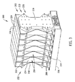
- FIG. 3 is a perspective view of a battery assembly 200
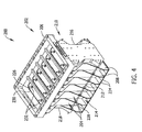
- FIG. 4 is an alternative perspective view of battery assembly 200.
- Battery assembly 200 includes a battery containment apparatus 202 and a plurality of battery cells 204 positioned within battery containment apparatus 202.
- Battery containment apparatus 202 includes a chassis base 206, a plurality of divider sheets 208 coupled to chassis base 206, a compression plate assembly 210, and at least one tensioning member 212.
- the plurality of divider sheets 208 are spaced from each other along chassis base 206 such that a battery cell slot 214 is defined between adjacent divider sheets 208.
- At least one battery cell 204 is positioned within each battery cell slot 214 thereby defining the plurality of battery cells 204.
- Compression plate assembly 210 includes a first compression plate 216 and a second compression plate 218 coupled to at least one divider sheet 208 of the plurality at opposing ends of battery containment apparatus 202. More specifically, first compression plate 216 is coupled to a divider sheet 208 at a first end 220 of battery containment apparatus 202 and second compression plate 218 is coupled to a divider sheet 208 at an opposing second end 222 of battery containment apparatus 202. As such, as will be described in more detail below, tensioning members 212 are coupled between first and second compression plates 216 and 218 to compressively hold the plurality of battery cells 204 between the plurality of divider sheets 208.
- Battery containment apparatus 202 further includes a plurality of thermally conductive fins 224 each coupled to at least one divider sheet 208 and extending between adjacent divider sheets 208.
- thermally conductive fins 224 are integrally formed with each divider sheet 208.
- the plurality of thermally conductive fins 224 are positioned to radiate heat generated by the plurality of battery cells 204. More specifically, each battery cell 204 includes a first end 226 coupled to chassis base 206, and an opposing second end 228.
- the plurality of thermally conductive fins 224 are positioned adjacent to second ends 228 of the plurality of battery cells 204.
- thermally conductive fins 224 at least partially define battery slots 214 and facilitate radiating heat from within battery assembly 200 towards thermally conductive fins 224.
- chassis base 206 includes a plurality of battery cell openings 230 sized to receive at least one battery cell 204 therein. More specifically, first ends 226 of each battery cell 204 extend at least partially through battery cell openings 230 such that battery cell electrodes 232 are exposed on an underside of chassis base 206. As such, the plurality of battery cells 204 can be coupled together, either in series or in parallel, to provide power to electrical systems of a vehicle, such as aircraft 102.
- Battery containment apparatus 202 may be fabricated from any material that enables battery assembly 200 to function as described herein. More specifically, at least one of chassis base 206 and compression plate assembly 210 are formed from a thermoplastic material such that battery assembly 200 is at least about 80 percent mass efficient and, more specifically, is at least about 85 percent mass efficient. As used herein, “mass efficient” refers to a mass of battery cells 204 as a percentage of a total mass of battery assembly 200. As such, at least one of chassis base 206 and compression plate assembly 210 are formed from a thermoplastic material such that the mass of the plurality of battery cells 204 is greater than about 80 percent of the total mass of battery assembly 200. In one implementation, battery cells 204 are LSE series lithium ion battery cells manufactured by GS YuasaTM ("GS Yuasa” is a registered trademark of GS Yuasa Corporation of Kyoto-shi, Japan).
- chassis base 206 and compression plate assembly 210 are formed from a thermoplastic material having a coefficient of thermal expansion defined within a range between about 10.0 (10 -6 in/(in*°F)) and about 20.0 (10 -6 in/(in*°F)).
- battery cells 204 include an outer casing 234 formed from a material having a first coefficient of thermal expansion and the thermoplastic material has a second coefficient of thermal expansion.
- outer casing 234 may be at least partially formed from a metallic material such as aluminum having a coefficient of thermal expansion of about 12.3 (10 -6 in/(in*°F)), and the thermoplastic material is selected such that a difference between the first and second coefficients of thermal expansion is within a predetermined threshold.
- Example thermoplastic material includes, but is not limited to, a polyetherketoneketone (PEKK) material, and a polyetherimide material. More specifically, the PEKK material includes carbon fiber material (not shown) dispersed therein, thereby forming a carbon fiber reinforced polymer (CFRP) material having a coefficient of thermal expansion of about 15.0 (10 -6 in/(in*°F)). In one embodiment, the CFRP material includes carbon fiber having a weight percentage of about 15 percent within the CFRP material. As such, the CFRP material is capable of bleeding static charge generated by battery cells 204 without being highly electrically conductive to facilitate reducing the likelihood of electrical shorts, and has a coefficient of thermal expansion closely matched with that of battery cells 204.
- PEKK polyetherketoneketone
- CFRP carbon fiber reinforced polymer
- the CFRP material is thermally insulative such that heat generated by battery cells 204 is radiated from battery containment apparatus 202 through thermally conductive fins 224.
- the thermoplastic material has a coefficient of thermal expansion such that the difference in coefficients of thermal expansion is greater than the predetermined threshold, and additional components are utilized to compensate for expansion mismatches between the two materials.
- Thermally conductive fins 224 may be fabricated from any material that enables battery assembly 200 to function as described herein. More specifically, thermally conductive fins 224 may be fabricated from a material having a greater thermal conductivity than the material used to fabricate battery containment apparatus 202. For example, in one implementation, thermally conductive fins 224 are fabricated from a metallic material having at least one layer 236 of a high-emittance coating material applied to an outer surface of the plurality of thermally conductive fins 224. The high-emittance coating material facilitates increasing the thermal conductivity of the metallic material used to fabricate thermally conductive fins 224.
- FIG. 5 is a perspective view of a compression plate 216/218 that may be used with battery assembly 200 (shown in FIG. 3 )
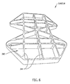
- FIG. 6 is a partially transparent perspective view of compression plate 216/218
- FIG. 7 is an end view of compression plate 216/218.
- compression plate 216/218 includes a first face sheet 238 for coupling to divider sheets 208 (shown in FIG. 3 ), an opposing second face sheet 240, and at least one rib structure 244 extending therebetween.
- First and second face sheets 238 and 240 are separated from each other by a distance such that at least one convection cavity 242 is defined by first and second face sheets 238 and 240 and the at least one rib structure 244 within first and second compression plates 216 and 218.
- the at least one rib structure 244 provides strength and structural stiffness for compression plate 216/218, and convection cavity 242 facilitates thermally insulating battery cells 204 within battery containment apparatus 202 (each shown in FIG. 3 ).
- First and second face sheets 238 and 240 are also separated from each other by a distance to facilitate providing micrometeroid and debris (MMOD) protection for battery assembly 200. More specifically, at least a portion of first face sheet 238 couples to at least one divider sheet 208 and second face sheet 240 is positioned a distance from the at least one divider sheet 208. As such, when impacted by a micrometeroid or debris, second face sheet 240 facilitates fragmenting the micrometeroid or debris, and first face sheet 238 is capable of blocking the fragments penetrating therethrough.
- MMOD micrometeroid and debris
- compression plate 216/218 includes a central portion 246 for coupling to the at least one divider sheet 208, as will be explained in more detail below, and at least one outer portion 248 extending from a side edge 250 of central portion 246 and extending outwardly from the at least one divider sheet 208.
- tensioning members 212 are coupled between first and second compression plates 216 and 218 to compressively hold the plurality of battery cells 204 between the plurality of divider sheets 208.
- each outer portion 248 includes an aperture 252 sized to receive at least one tensioning member 212 therethrough.
- the at least one outer portion 248 is configured to bend towards the at least one divider sheet 208 when loaded in tension by the at least one tensioning member 212 such that central portion 246 is compressively held against the at least one divider sheet 208.
- first face sheet 238 includes a first portion 254 extending along central portion 246 of compression plate 216/218 and a second portion 256 extending along outer portions 248 of compression plate 216/218.
- outer portions 248 extend outwardly from the at least one divider sheet 208 when compression plate 216/218 is coupled thereto.
- first face sheet 238 has a non-planar configuration such that second portions 256 extend at an oblique orientation relative to first portion 254.
- central portion 246 of compression plate 216/218 provides a more uniform and centrally located pressure distribution across the plurality of battery cells 204.
- first face sheet 238 has a convex outer curvature.
- FIG. 8 is a schematic illustration of an additive manufacturing system 258.
- additive manufacturing system 258 includes a controller 260 coupled in communication with a robotic device 262.
- Robotic device 262 is any suitable computer numerically controlled device that facilitates successively creating one or more layers of thermoplastic material to form an object, such as compression plate 216/218.
- Controller 260 includes a memory 264 (i.e., a non-transitory computer-readable medium) and a processor 266 coupled to memory 264 for executing programmed instructions.
- Processor 266 may include one or more processing units (e.g., in a multi-core configuration) and/or include a cryptographic accelerator (not shown).
- Controller 260 is programmable to perform one or more operations described herein by programming memory 264 and/or processor 266.
- processor 266 may be programmed by encoding an operation as executable instructions and providing the executable instructions in memory 264.
- Processor 266 may include, but is not limited to, a general purpose central processing unit (CPU), a microcontroller, a reduced instruction set computer (RISC) processor, an open media application platform (OMAP), an application specific integrated circuit (ASIC), a programmable logic circuit (PLC), and/or any other circuit or processor capable of executing the functions described herein.
- the methods described herein may be encoded as executable instructions embodied in a computer-readable medium including, without limitation, a storage device and/or a memory device. Such instructions, when executed by processor 266, cause processor 266 to perform at least a portion of the functions described herein.
- processor 266 When executed by processor 266, cause processor 266 to perform at least a portion of the functions described herein.
- the above examples are exemplary only, and thus are not intended to limit in any way the definition and/or meaning of the term processor.
- Memory 264 is one or more devices that enable information such as executable instructions and/or other data to be stored and retrieved.
- Memory 264 may include one or more computer-readable media, such as, without limitation, dynamic random access memory (DRAM), synchronous dynamic random access memory (SDRAM), static random access memory (SRAM), a solid state disk, and/or a hard disk.
- DRAM dynamic random access memory
- SDRAM synchronous dynamic random access memory
- SRAM static random access memory
- Solid state disk and/or a hard disk.
- Memory 264 may be configured to store, without limitation, executable instructions, operating systems, applications, resources, installation scripts and/or any other type of data suitable for use with the methods and systems described herein.
- Non-transitory memory 264 Instructions for operating systems and applications are located in a functional form on non-transitory memory 264 for execution by processor 266 to perform one or more of the processes described herein.
- These instructions may be embodied on different physical or tangible computer-readable media, such as memory 264 or another memory, such as a computer-readable media (not shown), which may include, without limitation, a flash drive and/or thumb drive.
- instructions may be located in a functional form on non-transitory computer-readable media, which may include, without limitation, smart-media (SM) memory, compact flash (CF) memory, secure digital (SD) memory, memory stick (MS) memory, multimedia card (MMC) memory, embedded-multimedia card (e-MMC), and micro-drive memory.
- the computer-readable media may be selectively insertable and/or removable from controller 260 to permit access and/or execution by processor 266. In an alternative implementation, the computer-readable media is not removable.
- At least one of chassis base 206 and compression plates 216 and 218 can be fabricated using an additive manufacturing technique or 3D printing technique, such as selective laser sintering (SLS) or fusion deposition modeling (FDM).
- SLS selective laser sintering
- FDM fusion deposition modeling
- SLS is a process for generating a material from a powdered compound.
- the powdered compound is distributed onto a work surface, and a device, such as a laser, is directed onto at least a portion of the powder, fusing those powder particles together to form a portion of a sintered material.
- FDM is a process that generally includes forming plastic threads or filaments, which are fed through a heated extrusion nozzle. The nozzle at least partially melts the filaments, and the filaments are extruded onto a work surface. The thin filament of plastic cools and hardens on the surface, and successive layers of the filaments are then extruded onto the hardened plastic.
- controller 260 generates programmed instructions for forming compression plate 216/218 based on a virtual model representing compression plate 216/218.
- the virtual model may be either generated by controller 260, or imported from a remote source.
- Controller 260 then executes the programmed instructions to direct additive manufacturing of compression plate 216/218 in which one or more layers of thermoplastic material are successively created until features of compression plate 216/218 correspond to the virtual model. More specifically, the programmed instructions are transmitted to robotic device 262 for execution thereof.
- a method 300 of forming battery assembly 200 is described herein.
- the method includes coupling 302 plurality of divider sheets 208 to chassis base 206, wherein the plurality of divider sheets 208 are spaced from each other such that battery cell slot 214 is defined between adjacent divider sheets 208.
- the method also includes coupling 304 first compression plate 216 and second compression plate 218 to at least one divider sheet 208 of the plurality at opposing ends of battery assembly 200, coupling 306 at least one tensioning member 212 between first and second compression plates 216 and 218, and positioning 308 at least one battery cell 204 within each battery cell slot 214 thereby defining a plurality of battery cells 204, wherein first and second compression plates 216 and 218 are configured to compressively hold the plurality of battery cells 204 between the plurality of divider sheets 208.
- At least one of chassis base 206 and first and second compression plates 216 and 218 are formed from a thermoplastic material such that the mass of the plurality of battery cells 204 is greater than about 80 percent of the mass of the battery assembly 200.
- the at least one battery cell 204 includes outer casing 234 formed from a material having a first coefficient of thermal expansion.
- the method further includes forming at least one of chassis base 206 and the first and second compression plates 216 and 218 from the thermoplastic material having a second coefficient of thermal expansion, such that a difference between the first and second coefficients of thermal expansion is within a predetermined threshold.
- the method further includes forming at least one of chassis base 206, the plurality of divider sheets 208, and the first and second compression plates 216 and 218 from a polyetherketoneketone (PEKK) material.
- PEKK polyetherketoneketone
- the method further includes forming at least one of chassis base 206 and the first and second compression plates 216 and 218 from the polyetherketoneketone (PEKK) material having carbon fiber material dispersed therein, thereby forming a carbon fiber reinforced polymer (CFRP) material.
- PEKK polyetherketoneketone
- the method further includes coupling thermally conductive fin 224 to at least one divider sheet 208 of the plurality, thermally conductive fin 224 extending at least partially between adjacent divider sheets 208 and configured to radiate heat generated by the plurality of battery cells 204.
- Thermally conductive fin 224 is formed from a metallic material having at least one layer 236 of high-emittance coating material applied thereto.
- Coupling first compression plate 216 and second compression plate 218 to at least one divider sheet 208 includes coupling central portion 246 of first and second compression plates 216 and 218 to the at least one divider sheet 208, and extending at least one outer portion 248 from side edge 250 of central portion 246, the at least one outer portion 248 extending outwardly from the at least one divider sheet 208.
- At least one tensioning member 212 is coupled between the at least one outer portion 248 of first and second compression plates 216 and 218, wherein, when loaded in tension by the at least one tensioning member 212, central portion 246 is compressively held against the at least one divider sheet 208 such that the at least one outer portion 248 bends towards the at least one divider sheet 208.
- a method 400 of forming a compression plate for use in a battery containment apparatus includes generating 402 programmed instructions for forming compression plate 216/218 that includes first face sheet 238, an opposing second face sheet 240, and at least one rib structure 244extending therebetween, wherein the programmed instructions are generated based on a virtual model representing compression plate 216/218.
- the method also includes executing 404 the programmed instructions to direct additive manufacturing of compression plate 216/218 in which one or more layers of thermoplastic material are successively created until features of compression plate 216/218 correspond to the virtual model.
- Executing the programmed instructions includes forming compression plate 216/218 via at least one of a selective laser sintering (SLS) additive manufacturing technique and a fusion deposition modeling (FDM) additive manufacturing technique.
- the method also includes successively creating one or more layers of a polyetherketoneketone (PEKK) material having carbon fiber material dispersed therein.
- PEKK polyetherketoneketone
- Executing the programmed instructions further includes forming central portion 246 of compression plate 216/218, and forming at least one outer portion 248 extending from side edge 250 of central portion 246.
- the method further includes forming first portion 254 of first face sheet 238 that extends along central portion 246, and forming second portion 256 of first face sheet 238 that extends along the at least one outer portion 248, wherein second portion 256 extends in an oblique orientation relative to first portion 254.
- the method further includes defining an aperture in the at least one outer portion 248, aperture 252 sized to receive at least one tensioning member 212 therethrough.
- Executing the programmed instructions further includes forming first and second face sheets 238 and 240 a distance from each other such that at least one convection cavity 242 is defined by first and second face sheets 238 and 240 and the at least one rib structure 244 within compression plate 216/218. Executing the programmed instructions further includes forming a plurality of rib structures 244 that interconnect to at least partially define a plurality of convection cavities 242 within compression plate 216/218.
Landscapes
- Engineering & Computer Science (AREA)
- Chemical & Material Sciences (AREA)
- Manufacturing & Machinery (AREA)
- Chemical Kinetics & Catalysis (AREA)
- Electrochemistry (AREA)
- General Chemical & Material Sciences (AREA)
- Materials Engineering (AREA)
- Physics & Mathematics (AREA)
- Mechanical Engineering (AREA)
- Remote Sensing (AREA)
- Aviation & Aerospace Engineering (AREA)
- Automation & Control Theory (AREA)
- General Physics & Mathematics (AREA)
- Human Computer Interaction (AREA)
- Optics & Photonics (AREA)
- Combustion & Propulsion (AREA)
- Battery Mounting, Suspending (AREA)
- Secondary Cells (AREA)
- Sealing Battery Cases Or Jackets (AREA)
Abstract
Description
- The field of the present disclosure relates generally to battery systems and, more specifically, to a lightweight battery containment apparatus for housing a plurality of battery cells in spacecraft and other vehicles.
- At least some known vehicles include one or more battery packs for providing power to electrical systems of the vehicles. Battery packs generally include a plurality of individual battery cells positioned within a battery containment apparatus. The battery cells are coupled together, either in series or in parallel, to provide power to the electrical systems of the vehicle. In the aerospace industry, the battery containment apparatus is designed to account for various considerations that facilitate efficient operation of the vehicle. For example, when used in at least some known spacecraft, the battery containment apparatus is designed to be lightweight, capable of thermally insulating the battery cells, and formed from material having a coefficient of thermal expansion closely matched with the battery cells. As such, components of the battery containment apparatus are typically formed from a metallic material such as aluminum. Components formed from metallic materials are generally fabricated by machining a work piece into a desired shape. However, machining a metallic work piece can be a time-consuming and laborious task, and the shape of the final product is generally limited by the machining process. Moreover, components formed from metallic material are generally good thermal conductors, which sometimes requires thermally isolating the battery cell from the associated vehicle. In addition, metallic material is generally electrically conductive, which can result in the formation of electrical shorts within the battery cell.
- In one known aerospace application, such as a spacecraft utilizing all-electric propulsion, the mass efficiency of the battery cell assembly is of particular importance. Typically, ion propulsion systems are extremely efficient, but also have very low thrust capabilities. This can result in long transfer orbit duration to geosynchronous orbit, which can delay the service start date of the satellite. As such, an overall design goal for at least some known spacecraft is to reduce the mass of components loaded thereon to enable the accommodation of additional revenue generating payload without increasing transfer orbit duration.
- According to the present invention, a battery assembly is provided. The assembly includes a battery containment apparatus including a chassis base and a plurality of divider sheets coupled to the chassis base, wherein the plurality of divider sheets are spaced from each other such that a battery cell slot is defined between adjacent divider sheets. The apparatus further includes a compression plate assembly including a first compression plate and a second compression plate coupled to at least one divider sheet of the plurality at opposing ends of the battery containment apparatus, and at least one tensioning member coupled between the first and second compression plates. At least one battery cell is positioned within each battery cell slot thereby defining a plurality of battery cells, and the first and second compression plates are configured to compressively hold the plurality of battery cells between the plurality of divider sheets. At least one of the chassis base and the compression plate assembly are formed from a thermoplastic material.
- According to the present invention a satellite is also provided. The satellite includes a battery assembly, preferably as referred to above, configured to power the satellite. The battery assembly includes a battery containment apparatus including a chassis base and a plurality of divider sheets coupled to the chassis base, wherein the plurality of divider sheets are spaced from each other such that a battery cell slot is defined between adjacent divider sheets. The apparatus further includes a compression plate assembly including a first compression plate and a second compression plate coupled to at least one divider sheet of the plurality at opposing ends of the battery containment apparatus, and at least one tensioning member coupled between the first and second compression plates. At least one battery cell is positioned within each battery cell slot thereby defining a plurality of battery cells, and the first and second compression plates are configured to compressively hold the plurality of battery cells between the plurality of divider sheets. At least one of the chassis base and the compression plate assembly are formed from a thermoplastic material.
- The present invention also provides a method of forming the battery assembly.The method includes coupling a plurality of divider sheets to a chassis base, wherein the plurality of divider sheets are spaced from each other such that a battery cell slot is defined between adjacent divider sheets. The method further includes coupling a first compression plate and a second compression plate to at least one divider sheet of the plurality at opposing ends of the battery cell assembly, coupling at least one tensioning member between the first and second compression plates, and positioning at least one battery cell within each battery cell slot thereby defining a plurality of battery cells. The first and second compression plates are configured to compressively hold the plurality of battery cells between the plurality of divider sheets. At least one of the chassis base and the first and second compression plates are formed from a thermoplastic material.
- The present invention also provides a method of forming a compression plate for use in a battery containment apparatus is provided. The method includes generating programmed instructions for forming the compression plate that includes a first face sheet, an opposing second face sheet, and at least one rib structure extending therebetween. The programmed instructions are generated based on a virtual model representing the compression plate. The method further includes executing the programmed instructions to direct additive manufacturing of the compression plate in which one or more layers of thermoplastic material are successively created until features of the compression plate correspond to the virtual model.
-
-
FIG. 1 is a flow diagram of an aircraft production and service method. -
FIG. 2 is a block diagram of an aircraft. -
FIG. 3 is a perspective view of a battery assembly. -
FIG. 4 is an alternative perspective view of the battery assembly shown inFIG. 3 . -
FIG. 5 is a perspective view of a compression plate that may be used with the battery assembly shown inFIG. 3 . -
FIG. 6 is a partially transparent perspective view of the compression plate shown inFIG. 5 . -
FIG. 7 is an end view of the compression plate shown inFIG. 5 . -
FIG. 8 is a schematic illustration of an additive manufacturing system. -
FIG. 9 is a flow diagram illustrating a method of forming a battery assembly. -
FIG. 10 is a flow diagram illustrating a method of forming a compression plate for use in a battery containment apparatus. - The present invention relates to a battery assembly, a battery containment apparatus, and related methods of manufacture. The battery cell includes a chassis base, a plurality of divider sheets, a battery cell positioned between adjacent divider sheets, and compression plates on opposing ends of the batter containment apparatus. At least one of the chassis base and the compression plates are fabricated from a thermoplastic material, such as a polyetherketoneketone material having carbon fiber material dispersed therein. Forming components of the battery containment apparatus by the thermoplastic material facilitates reducing the mass of the battery containment apparatus, thereby increasing the mass efficiency of the battery assembly including the battery cells. The thermoplastic material has one or more characteristics that facilitate efficient operation of a vehicle implementing the battery assembly. For example, the thermoplastic material is lightweight, thermally insulative, and electrically conductive to facilitate dissipating static charge. Moreover, forming the components from thermoplastic material enables them to be manufactured via one or more additive manufacturing techniques. As such, as will be described in more detail below, one or more of the components may be formed with features that enable the battery containment apparatus to compressively hold battery cells therein in a more efficient manner.
- Referring to the drawings, the invention may be described in the context of an aircraft manufacturing and service method 100 (shown in
FIG. 1 ) and via an aircraft 102 (shown inFIG. 2 ). During pre-production, including specification and design 104 data ofaircraft 102 may be used during the manufacturing process and other materials associated with the airframe may be procured 106. During production, component andsubassembly manufacturing 108 andsystem integration 110 ofaircraft 102 occurs, prior toaircraft 102 entering its certification anddelivery process 112. Upon successful satisfaction and completion of airframe certification,aircraft 102 may be placed inservice 114. While in service by a customer,aircraft 102 is scheduled for periodic, routine, and scheduled maintenance andservice 116, including any modification, reconfiguration, and/or refurbishment, for example. In alternative implementations, manufacturing andservice method 100 may be implemented via platforms other than an aircraft. - Each portion and process associated with aircraft manufacturing and/or
service 100 may be performed or completed by a system integrator, a third party, and/or an operator (e.g., a customer). For the purposes of this description, a system integrator may include without limitation any number of aircraft manufacturers and major-system subcontractors; a third party may include without limitation any number of venders, subcontractors, and suppliers; and an operator may be an airline, leasing company, military entity, service organization, and so on. - As shown in
FIG. 2 ,aircraft 102 produced viamethod 100 may include anairframe 118 having a plurality ofsystems 120 and aninterior 122. Examples of high-level systems 120 include one or more of apropulsion system 124, anelectrical system 126, ahydraulic system 128, and/or anenvironmental system 130. Any number of other systems may be included. - Apparatus and methods embodied herein may be employed during any one or more of the stages of
method 100. For example, components or subassemblies corresponding to component andsubassembly production process 108 may be fabricated or manufactured in a manner similar to components or subassemblies produced whileaircraft 102 is inservice 114. Also, one or more apparatus implementations, method implementations, or a combination thereof may be utilized during the production stages 108 and 110, for example, by substantially expediting assembly of, and/or reducing the cost of assembly ofaircraft 102. Similarly, one or more of apparatus implementations, method implementations, or a combination thereof may be utilized whileaircraft 102 is being serviced or maintained, for example, during scheduled maintenance andservice 116. - As used herein, the term "aircraft" may include, but is not limited to only including, spacecraft, airplanes, unmanned aerial vehicles (UAVs), gliders, helicopters, and/or any other object that travels through airspace. Further, in an alternative implementation, the aircraft manufacturing and service method described herein may be used in any manufacturing and/or service operation.
-
FIG. 3 is a perspective view of abattery assembly 200, andFIG. 4 is an alternative perspective view ofbattery assembly 200.Battery assembly 200 includes abattery containment apparatus 202 and a plurality ofbattery cells 204 positioned withinbattery containment apparatus 202.Battery containment apparatus 202 includes achassis base 206, a plurality ofdivider sheets 208 coupled tochassis base 206, acompression plate assembly 210, and at least one tensioningmember 212. The plurality ofdivider sheets 208 are spaced from each other alongchassis base 206 such that abattery cell slot 214 is defined betweenadjacent divider sheets 208. At least onebattery cell 204 is positioned within eachbattery cell slot 214 thereby defining the plurality ofbattery cells 204. -
Compression plate assembly 210 includes afirst compression plate 216 and asecond compression plate 218 coupled to at least onedivider sheet 208 of the plurality at opposing ends ofbattery containment apparatus 202. More specifically,first compression plate 216 is coupled to adivider sheet 208 at afirst end 220 ofbattery containment apparatus 202 andsecond compression plate 218 is coupled to adivider sheet 208 at an opposingsecond end 222 ofbattery containment apparatus 202. As such, as will be described in more detail below, tensioningmembers 212 are coupled between first andsecond compression plates battery cells 204 between the plurality ofdivider sheets 208. -
Battery containment apparatus 202 further includes a plurality of thermallyconductive fins 224 each coupled to at least onedivider sheet 208 and extending betweenadjacent divider sheets 208. In one implementation, thermallyconductive fins 224 are integrally formed with eachdivider sheet 208. The plurality of thermallyconductive fins 224 are positioned to radiate heat generated by the plurality ofbattery cells 204. More specifically, eachbattery cell 204 includes afirst end 226 coupled tochassis base 206, and an opposingsecond end 228. The plurality of thermallyconductive fins 224 are positioned adjacent to second ends 228 of the plurality ofbattery cells 204. By extending betweenadjacent divider sheets 208, thermallyconductive fins 224 at least partially definebattery slots 214 and facilitate radiating heat from withinbattery assembly 200 towards thermallyconductive fins 224. - Referring to
FIG. 4 ,chassis base 206 includes a plurality ofbattery cell openings 230 sized to receive at least onebattery cell 204 therein. More specifically, first ends 226 of eachbattery cell 204 extend at least partially throughbattery cell openings 230 such thatbattery cell electrodes 232 are exposed on an underside ofchassis base 206. As such, the plurality ofbattery cells 204 can be coupled together, either in series or in parallel, to provide power to electrical systems of a vehicle, such asaircraft 102. -
Battery containment apparatus 202 may be fabricated from any material that enablesbattery assembly 200 to function as described herein. More specifically, at least one ofchassis base 206 andcompression plate assembly 210 are formed from a thermoplastic material such thatbattery assembly 200 is at least about 80 percent mass efficient and, more specifically, is at least about 85 percent mass efficient. As used herein, "mass efficient" refers to a mass ofbattery cells 204 as a percentage of a total mass ofbattery assembly 200. As such, at least one ofchassis base 206 andcompression plate assembly 210 are formed from a thermoplastic material such that the mass of the plurality ofbattery cells 204 is greater than about 80 percent of the total mass ofbattery assembly 200. In one implementation,battery cells 204 are LSE series lithium ion battery cells manufactured by GS Yuasa™ ("GS Yuasa" is a registered trademark of GS Yuasa Corporation of Kyoto-shi, Japan). - Moreover, at least one of
chassis base 206 andcompression plate assembly 210 are formed from a thermoplastic material having a coefficient of thermal expansion defined within a range between about 10.0 (10-6 in/(in*°F)) and about 20.0 (10-6 in/(in*°F)). For example, in the exemplary implementation,battery cells 204 include anouter casing 234 formed from a material having a first coefficient of thermal expansion and the thermoplastic material has a second coefficient of thermal expansion. More specifically,outer casing 234 may be at least partially formed from a metallic material such as aluminum having a coefficient of thermal expansion of about 12.3 (10-6 in/(in*°F)), and the thermoplastic material is selected such that a difference between the first and second coefficients of thermal expansion is within a predetermined threshold. In one implementation, the predetermined threshold is about 25 percent. Example thermoplastic material includes, but is not limited to, a polyetherketoneketone (PEKK) material, and a polyetherimide material. More specifically, the PEKK material includes carbon fiber material (not shown) dispersed therein, thereby forming a carbon fiber reinforced polymer (CFRP) material having a coefficient of thermal expansion of about 15.0 (10-6 in/(in*°F)). In one embodiment, the CFRP material includes carbon fiber having a weight percentage of about 15 percent within the CFRP material. As such, the CFRP material is capable of bleeding static charge generated bybattery cells 204 without being highly electrically conductive to facilitate reducing the likelihood of electrical shorts, and has a coefficient of thermal expansion closely matched with that ofbattery cells 204. Moreover, the CFRP material is thermally insulative such that heat generated bybattery cells 204 is radiated frombattery containment apparatus 202 through thermallyconductive fins 224. In an alternative implementation, the thermoplastic material has a coefficient of thermal expansion such that the difference in coefficients of thermal expansion is greater than the predetermined threshold, and additional components are utilized to compensate for expansion mismatches between the two materials. - Thermally
conductive fins 224 may be fabricated from any material that enablesbattery assembly 200 to function as described herein. More specifically, thermallyconductive fins 224 may be fabricated from a material having a greater thermal conductivity than the material used to fabricatebattery containment apparatus 202. For example, in one implementation, thermallyconductive fins 224 are fabricated from a metallic material having at least onelayer 236 of a high-emittance coating material applied to an outer surface of the plurality of thermallyconductive fins 224. The high-emittance coating material facilitates increasing the thermal conductivity of the metallic material used to fabricate thermallyconductive fins 224. -
FIG. 5 is a perspective view of acompression plate 216/218 that may be used with battery assembly 200 (shown inFIG. 3 ),FIG. 6 is a partially transparent perspective view ofcompression plate 216/218, andFIG. 7 is an end view ofcompression plate 216/218. In the exemplary implementation,compression plate 216/218 includes afirst face sheet 238 for coupling to divider sheets 208 (shown inFIG. 3 ), an opposingsecond face sheet 240, and at least onerib structure 244 extending therebetween. First andsecond face sheets convection cavity 242 is defined by first andsecond face sheets rib structure 244 within first andsecond compression plates rib structure 244 provides strength and structural stiffness forcompression plate 216/218, andconvection cavity 242 facilitates thermally insulatingbattery cells 204 within battery containment apparatus 202 (each shown inFIG. 3 ). - First and
second face sheets battery assembly 200. More specifically, at least a portion offirst face sheet 238 couples to at least onedivider sheet 208 andsecond face sheet 240 is positioned a distance from the at least onedivider sheet 208. As such, when impacted by a micrometeroid or debris,second face sheet 240 facilitates fragmenting the micrometeroid or debris, andfirst face sheet 238 is capable of blocking the fragments penetrating therethrough. - Moreover,
compression plate 216/218 includes acentral portion 246 for coupling to the at least onedivider sheet 208, as will be explained in more detail below, and at least oneouter portion 248 extending from aside edge 250 ofcentral portion 246 and extending outwardly from the at least onedivider sheet 208. As described above, tensioningmembers 212 are coupled between first andsecond compression plates battery cells 204 between the plurality ofdivider sheets 208. More specifically, eachouter portion 248 includes anaperture 252 sized to receive at least one tensioningmember 212 therethrough. As such, the at least oneouter portion 248 is configured to bend towards the at least onedivider sheet 208 when loaded in tension by the at least one tensioningmember 212 such thatcentral portion 246 is compressively held against the at least onedivider sheet 208. - Referring to
FIG. 7 ,first face sheet 238 includes afirst portion 254 extending alongcentral portion 246 ofcompression plate 216/218 and asecond portion 256 extending alongouter portions 248 ofcompression plate 216/218. As described above,outer portions 248 extend outwardly from the at least onedivider sheet 208 whencompression plate 216/218 is coupled thereto. More specifically,first face sheet 238 has a non-planar configuration such thatsecond portions 256 extend at an oblique orientation relative tofirst portion 254. As such, when loaded in tension by the at least one tensioningmember 212,central portion 246 ofcompression plate 216/218 provides a more uniform and centrally located pressure distribution across the plurality ofbattery cells 204. In an alternative implementation,first face sheet 238 has a convex outer curvature. -
FIG. 8 is a schematic illustration of anadditive manufacturing system 258. In the exemplary implementation,additive manufacturing system 258 includes acontroller 260 coupled in communication with arobotic device 262.Robotic device 262 is any suitable computer numerically controlled device that facilitates successively creating one or more layers of thermoplastic material to form an object, such ascompression plate 216/218.Controller 260 includes a memory 264 (i.e., a non-transitory computer-readable medium) and aprocessor 266 coupled tomemory 264 for executing programmed instructions.Processor 266 may include one or more processing units (e.g., in a multi-core configuration) and/or include a cryptographic accelerator (not shown).Controller 260 is programmable to perform one or more operations described herein byprogramming memory 264 and/orprocessor 266. For example,processor 266 may be programmed by encoding an operation as executable instructions and providing the executable instructions inmemory 264. -
Processor 266 may include, but is not limited to, a general purpose central processing unit (CPU), a microcontroller, a reduced instruction set computer (RISC) processor, an open media application platform (OMAP), an application specific integrated circuit (ASIC), a programmable logic circuit (PLC), and/or any other circuit or processor capable of executing the functions described herein. The methods described herein may be encoded as executable instructions embodied in a computer-readable medium including, without limitation, a storage device and/or a memory device. Such instructions, when executed byprocessor 266,cause processor 266 to perform at least a portion of the functions described herein. The above examples are exemplary only, and thus are not intended to limit in any way the definition and/or meaning of the term processor. -
Memory 264 is one or more devices that enable information such as executable instructions and/or other data to be stored and retrieved.Memory 264 may include one or more computer-readable media, such as, without limitation, dynamic random access memory (DRAM), synchronous dynamic random access memory (SDRAM), static random access memory (SRAM), a solid state disk, and/or a hard disk.Memory 264 may be configured to store, without limitation, executable instructions, operating systems, applications, resources, installation scripts and/or any other type of data suitable for use with the methods and systems described herein. - Instructions for operating systems and applications are located in a functional form on
non-transitory memory 264 for execution byprocessor 266 to perform one or more of the processes described herein. These instructions may be embodied on different physical or tangible computer-readable media, such asmemory 264 or another memory, such as a computer-readable media (not shown), which may include, without limitation, a flash drive and/or thumb drive. Further, instructions may be located in a functional form on non-transitory computer-readable media, which may include, without limitation, smart-media (SM) memory, compact flash (CF) memory, secure digital (SD) memory, memory stick (MS) memory, multimedia card (MMC) memory, embedded-multimedia card (e-MMC), and micro-drive memory. The computer-readable media may be selectively insertable and/or removable fromcontroller 260 to permit access and/or execution byprocessor 266. In an alternative implementation, the computer-readable media is not removable. - At least one of
chassis base 206 andcompression plates - For example,
controller 260 generates programmed instructions for formingcompression plate 216/218 based on a virtual model representingcompression plate 216/218. The virtual model may be either generated bycontroller 260, or imported from a remote source.Controller 260 then executes the programmed instructions to direct additive manufacturing ofcompression plate 216/218 in which one or more layers of thermoplastic material are successively created until features ofcompression plate 216/218 correspond to the virtual model. More specifically, the programmed instructions are transmitted torobotic device 262 for execution thereof. - A
method 300 of formingbattery assembly 200 is described herein. The method includescoupling 302 plurality ofdivider sheets 208 tochassis base 206, wherein the plurality ofdivider sheets 208 are spaced from each other such thatbattery cell slot 214 is defined betweenadjacent divider sheets 208. The method also includescoupling 304first compression plate 216 andsecond compression plate 218 to at least onedivider sheet 208 of the plurality at opposing ends ofbattery assembly 200, coupling 306 at least one tensioningmember 212 between first andsecond compression plates battery cell 204 within eachbattery cell slot 214 thereby defining a plurality ofbattery cells 204, wherein first andsecond compression plates battery cells 204 between the plurality ofdivider sheets 208. At least one ofchassis base 206 and first andsecond compression plates battery cells 204 is greater than about 80 percent of the mass of thebattery assembly 200. - The at least one
battery cell 204 includesouter casing 234 formed from a material having a first coefficient of thermal expansion. The method further includes forming at least one ofchassis base 206 and the first andsecond compression plates chassis base 206, the plurality ofdivider sheets 208, and the first andsecond compression plates chassis base 206 and the first andsecond compression plates - The method further includes coupling thermally
conductive fin 224 to at least onedivider sheet 208 of the plurality, thermallyconductive fin 224 extending at least partially betweenadjacent divider sheets 208 and configured to radiate heat generated by the plurality ofbattery cells 204. Thermallyconductive fin 224 is formed from a metallic material having at least onelayer 236 of high-emittance coating material applied thereto. - Coupling
first compression plate 216 andsecond compression plate 218 to at least onedivider sheet 208 includes couplingcentral portion 246 of first andsecond compression plates divider sheet 208, and extending at least oneouter portion 248 fromside edge 250 ofcentral portion 246, the at least oneouter portion 248 extending outwardly from the at least onedivider sheet 208. At least one tensioningmember 212 is coupled between the at least oneouter portion 248 of first andsecond compression plates member 212,central portion 246 is compressively held against the at least onedivider sheet 208 such that the at least oneouter portion 248 bends towards the at least onedivider sheet 208. - A
method 400 of forming a compression plate for use in a battery containment apparatus is also described herein. The method includes generating 402 programmed instructions for formingcompression plate 216/218 that includesfirst face sheet 238, an opposingsecond face sheet 240, and at least one rib structure 244extending therebetween, wherein the programmed instructions are generated based on a virtual model representingcompression plate 216/218. The method also includes executing 404 the programmed instructions to direct additive manufacturing ofcompression plate 216/218 in which one or more layers of thermoplastic material are successively created until features ofcompression plate 216/218 correspond to the virtual model. - Executing the programmed instructions includes forming
compression plate 216/218 via at least one of a selective laser sintering (SLS) additive manufacturing technique and a fusion deposition modeling (FDM) additive manufacturing technique. The method also includes successively creating one or more layers of a polyetherketoneketone (PEKK) material having carbon fiber material dispersed therein. - Executing the programmed instructions further includes forming
central portion 246 ofcompression plate 216/218, and forming at least oneouter portion 248 extending fromside edge 250 ofcentral portion 246. The method further includes formingfirst portion 254 offirst face sheet 238 that extends alongcentral portion 246, and formingsecond portion 256 offirst face sheet 238 that extends along the at least oneouter portion 248, whereinsecond portion 256 extends in an oblique orientation relative tofirst portion 254. The method further includes defining an aperture in the at least oneouter portion 248,aperture 252 sized to receive at least one tensioningmember 212 therethrough. Executing the programmed instructions further includes forming first andsecond face sheets 238 and 240 a distance from each other such that at least oneconvection cavity 242 is defined by first andsecond face sheets rib structure 244 withincompression plate 216/218. Executing the programmed instructions further includes forming a plurality ofrib structures 244 that interconnect to at least partially define a plurality ofconvection cavities 242 withincompression plate 216/218. - The following clauses also relate to the invention:
-
Clause 1. A battery assembly comprising a battery containment apparatus comprising: a chassis base; a plurality of divider sheets coupled to said chassis base, wherein said plurality of divider sheets are spaced from each other such that a battery cell slot is defined between adjacent divider sheets; a compression plate assembly comprising a first compression plate and a second compression plate coupled to at least one divider sheet of said plurality at opposing ends of said battery containment apparatus; and at least one tensioning member coupled between said first and second compression plates; and a battery cell positioned within each battery cell slot thereby defining a plurality of battery cells, wherein said first and second compression plates are configured to compressively hold said plurality of battery cells between said plurality of divider sheets, wherein at least one of said chassis base and said compression plate assembly are formed from a thermoplastic material. - Clause 2. The assembly in accordance with
clause 1, wherein at least one of said chassis base, said plurality of divider sheets, and said compression plate assembly are formed from the thermoplastic material such that the mass of said plurality of battery cells is greater than about 80 percent of the mass of the battery assembly. - Clause 3. The assembly in accordance with
clause 1 or 2 , wherein said battery cell comprises an outer casing formed from a material having a first coefficient of thermal expansion and the thermoplastic material has a second coefficient of thermal expansion, wherein a difference between the first and second coefficients of thermal expansion is within a predetermined threshold. - Clause 4. The assembly in accordance with any of the clauses 1-3 wherein the thermoplastic material comprises a carbon fiber reinforced polymer (CFRP) material including a polyetherketoneketone (PEKK) material having carbon fiber material dispersed therein.
- Clause 5. The assembly in accordance with any of the preceding clauses further comprising a plurality of thermally conductive fins configured to radiate heat generated by said plurality of battery cells, wherein each thermally conductive fin is coupled to at least one divider sheet and extends at least partially between adjacent divider sheets.
- Clause 6. The assembly in accordance with clause 5, wherein said plurality of battery cells comprise a first end coupled to said chassis base and an opposing second end, said plurality of thermally conductive fins positioned adjacent to said second end of said plurality of battery cells.
- Clause 7. The assembly in accordance with any of the preceding clauses wherein said first and second compression plates each comprise a first face sheet coupled to said at least one divider sheet, an opposing second face sheet, and at least one rib structure extending therebetween, wherein said first and second face sheets are separated from each other by a distance such that at least one convection cavity is defined by said first and second face sheets and said at least one rib structure within said first and second compression plates.
- Clause 8. The assembly in accordance with any of the preceding clauses wherein said first and second compression plates each comprise: a central portion coupled to said at least one divider sheet; and at least one outer portion extending from a side edge of said central portion and extending outwardly from said at least one divider sheet, wherein said at least one outer portion is configured to bend towards said at least one divider sheet when loaded in tension by said at least one tensioning member such that said central portion is compressively held against said at least one divider sheet.
- Clause 9. A satellite comprising: a battery assembly configured to power the satellite, said battery assembly comprising: a battery containment apparatus comprising: a chassis base; a plurality of divider sheets coupled to said chassis base, wherein said plurality of divider sheets are spaced from each other such that a battery cell slot is defined between adjacent divider sheets; a compression plate assembly comprising a first compression plate and a second compression plate coupled to at least one divider sheet of said plurality at opposing ends of said battery containment apparatus; and at least one tensioning member coupled between said first and second compression plates; and a battery cell positioned within each battery cell slot thereby defining a plurality of battery cells, wherein said first and second compression plates are configured to compressively hold said plurality of battery cells between said plurality of divider sheets, wherein at least one of said chassis base and said compression plate assembly are formed from a thermoplastic material.
- Clause 10. The satellite in accordance with clause 9 wherein at least one of said chassis base and said compression plate assembly are formed from the thermoplastic material having a coefficient of thermal expansion defined within a range between about 10.0 (10-6 in/(in*°F)) and about 20.0 (10-6 in/(in*°F)).
- Clause 11. The satellite in accordance with clause 9 or 10, wherein the thermoplastic material comprises a carbon fiber reinforced polymer (CFRP) material including a polyetherketoneketone (PEKK) material having carbon fiber material dispersed therein.
- Clause 12. The satellite in accordance with any of the clauses 9-11 further comprising a plurality of thermally conductive fins, each thermally conductive fin coupled to at least one divider sheet and extending at least partially between adjacent divider sheets.
- Clause 13. The satellite in accordance with clause 12, wherein said plurality of thermally conductive fins are fabricated from a metallic material having at least one layer of a high-emittance coating material applied thereto.
- Clause 14. The satellite in accordance with any of the clauses 9-13 wherein said first and second compression plates each comprise a first face sheet coupled to said at least one divider sheet, an opposing second face sheet, and at least one rib structure extending therebetween, wherein said first and second face sheets are separated from each other by a distance such that at least one convection cavity is defined by said first and second face sheets and said at least one rib structure within said first and second compression plates.
- Clause 15. The satellite in accordance with any of the clauses 9-14 wherein said first and second compression plates each comprise: a central portion coupled to said at least one divider sheet; and at least one outer portion extending from a side edge of said central portion and extending outwardly from said at least one divider sheet, wherein said at least one outer portion is configured to bend towards said at least one divider sheet when loaded in tension by said at least one tensioning member such that said central portion is compressively held against said at least one divider sheet.
- Clause 16. A method of forming a battery assembly, said method comprising: coupling a plurality of divider sheets to a chassis base, wherein the plurality of divider sheets are spaced from each other such that a battery cell slot is defined between adjacent divider sheets; coupling a first compression plate and a second compression plate to at least one divider sheet of the plurality at opposing ends of the battery cell assembly; coupling at least one tensioning member between the first and second compression plates; and positioning a battery cell within each battery cell slot thereby defining a plurality of battery cells, wherein the first and second compression plates are configured to compressively hold the plurality of battery cells between the plurality of divider sheets, wherein at least one of the chassis base and the first and second compression plates are formed from a thermoplastic material.
- Clause 17. The method in accordance with clause 16 further comprising forming at least one of the chassis base, the plurality of divider sheets, and the first and second compression plates from the thermoplastic material such that the mass of the plurality of battery cells is greater than about 80 percent of the mass of the battery assembly.
- Clause 18. The method in accordance with clause 16 or 17, wherein the battery cell includes an outer casing formed from a material having a first coefficient of thermal expansion, said method further comprising forming at least one of the chassis base and the first and second compression plates from the thermoplastic material having a second coefficient of thermal expansion, such that a difference between the first and second coefficients of thermal expansion is within a predetermined threshold.
- Clause 19. The method in accordance with any of the clauses 16-18 further comprising forming at least one of the chassis base and the first and second compression plates from a carbon fiber reinforced polymer (CFRP) material including a polyetherketoneketone (PEKK) material having carbon fiber material dispersed therein.
- Clause 20. The method in accordance with any of the clauses 16-20 further comprising coupling a thermally conductive fin to at least one divider sheet of the plurality, the thermally conductive fin extending at least partially between adjacent divider sheets and configured to radiate heat generated by the plurality of battery cells.
- Clause 21. The method in accordance with any of the clauses 16-20 wherein coupling a first compression plate and a second compression plate to at least one divider sheet comprises: coupling a central portion of the first and second compression plates to the at least one divider sheet; extending at least one outer portion from a side edge of the central portion, the at least one outer portion extending outwardly from the at least one divider sheet; and coupling the at least one tensioning member between the at least one outer portion of the first and second compression plates, wherein, when loaded in tension by the at least one tensioning member, the central portion is compressively held against the at least one divider sheet such that the at least one outer portion bends towards the at least one divider sheet.
- Clause 22. A method of forming a compression plate for use in a battery containment apparatus, said method comprising: generating programmed instructions for forming the compression plate that includes a first face sheet, an opposing second face sheet, and at least one rib structure extending therebetween, wherein the programmed instructions are generated based on a virtual model representing the compression plate; and executing the programmed instructions to direct additive manufacturing of the compression plate in which one or more layers of thermoplastic material are successively created until features of the compression plate correspond to the virtual model.
- Clause 23. The method in accordance with clause 22, wherein executing the programmed instructions comprises forming the compression plate via at least one of a selective laser sintering (SLS) additive manufacturing technique and a fusion deposition modeling (FDM) additive manufacturing technique.
- Clause 24. The method in accordance with clause 22 or 23, wherein executing the programmed instructions comprises successively creating one or more layers of a polyetherketoneketone (PEKK) material having carbon fiber material dispersed therein.
- Clause 25. The method in accordance with any of the clauses 22-24 wherein executing the programmed instructions comprises: forming a central portion of the compression plate; forming at least one outer portion extending from a side edge of the central portion; and defining an aperture in the at least one outer portion, the aperture sized to receive at least one tensioning member therethrough.
- Clause 26. The method in accordance with any of the clauses 22-25 further comprising: forming a first portion of the first face sheet that extends along the central portion; and forming a second portion of the first face sheet that extends along the at least one outer portion, the second portion extending in an oblique orientation relative to the first portion.
- Clause 27. The method in accordance with any of the clauses clause 22-26, wherein executing the programmed instructions comprises: forming the first and second face sheets a distance from each other such that at least one convection cavity is defined by the first and second face sheets and the at least one rib structure within the compression plate; and forming a plurality of rib structures that interconnect to at least partially define a plurality of convection cavities within the compression plate.
- This written description uses examples to disclose various implementations, including the best mode, and also to enable any person skilled in the art to practice the various implementations, including making and using any devices or systems and performing any incorporated methods. The patentable scope of the disclosure is defined by the claims, and may include other examples that occur to those skilled in the art. Such other examples are intended to be within the scope of the claims if they have structural elements that do not differ from the literal language of the claims, or if they include equivalent structural elements with insubstantial differences from the literal language of the claims.
Claims (14)
- A battery assembly (200) comprising:a battery containment apparatus (202) comprising:a chassis base (206);a plurality of divider sheets (208) coupled to said chassis base (206), wherein said plurality of divider sheets (208) are spaced from each other such that a battery cell (204) slot (214) is defined between adjacent divider sheets (208);a compression plate assembly (210) comprising a first compression plate (216) and a second compression plate (218) coupled to at least one divider sheet (208) of said plurality at opposing ends of said battery containment apparatus (202); andat least one tensioning member (212) coupled between said first and second compression plates (216/218); anda battery cell (204) positioned within each battery cell (204) slot (214) thereby defining a plurality of battery cells (204), wherein said first and second compression plates (216/218) are configured to compressively hold said plurality of battery cells (204) between said plurality of divider sheets (208),wherein at least one of said chassis base (206) and said compression plate assembly (210) are formed from a thermoplastic material.
- The assembly in accordance with Claim 1 wherein at least one of said chassis base (206), said plurality of divider sheets (208), and said compression plate assembly (210) are formed from the thermoplastic material such that the mass of said plurality of battery cells (204) is greater than about 80 percent of the mass of the battery assembly (200).
- The assembly in accordance with Claim 1or 2, wherein said battery cell (204) comprises an outer casing (234) formed from a material having a first coefficient of thermal expansion and the thermoplastic material has a second coefficient of thermal expansion, wherein a difference between the first and second coefficients of thermal expansion is within a predetermined threshold.
- The assembly in accordance with any of the preceding claims wherein the thermoplastic material comprises a carbon fiber reinforced polymer (CFRP) material including a polyetherketoneketone (PEKK) material having carbon fiber material dispersed therein.
- The assembly in accordance with any of the preceding claims further comprising a plurality of thermally conductive fins (224) configured to radiate heat generated by said plurality of battery cells (204), wherein each thermally conductive fin (224) is coupled to at least one divider sheet (208) and extends at least partially between adjacent divider sheets (208).
- The assembly in accordance with Claim 5, wherein said plurality of battery cells (204) comprise a first end (226) coupled to said chassis base (206) and an opposing second end (228), said plurality of thermally conductive fins (224) positioned adjacent to said second end (228) of said plurality of battery cells (204).
- The assembly in accordance with any of the preceding claims wherein said first and second compression plates (216/218) each comprise a first face sheet (238) coupled to said at least one divider sheet (208), an opposing second face sheet (240), and at least one rib structure (244) extending therebetween, wherein said first and second face sheets (238/240) are separated from each other by a distance such that at least one convection cavity (242) is defined by said first and second face sheets (238/240) and said at least one rib structure (244) within said first and second compression plates (216/218).
- The assembly in accordance with any of the preceding claims wherein said first and second compression plates (216/218) each comprise:a central portion (246) coupled to said at least one divider sheet (208); andat least one outer portion (248) extending from a side edge (250) of said central portion (246) and extending outwardly from said at least one divider sheet (208), wherein said at least one outer portion (248) is configured to bend towards said at least one divider sheet (208) when loaded in tension by said at least one tensioning member (212) such that said central portion (246) is compressively held against said at least one divider sheet (208).
- A method of forming a battery assembly (200), said method comprising:coupling a plurality of divider sheets (208) to a. chassis base (206), wherein the plurality of divider sheets (208) are spaced from each other such that a battery cell (204) slot (214) is defined between adjacent divider sheets (208);coupling a first compression plate (216) and a second compression plate (218) to at least one divider sheet (208) of the plurality at opposing ends of the battery cell (204) assembly;coupling at least one tensioning member (212) between the first and second compression plates (216/218); andpositioning a battery cell (204) within each battery cell (204) slot (214) thereby defining a plurality of battery cells (204), wherein the first and second compression plates (216/218) are configured to compressively hold the plurality of battery cells (204) between the plurality of divider sheets (208),wherein at least one of the chassis base (206) and the first and second compression plates (216/218) are formed from a thermoplastic material.
- The method in accordance with Claim 9 further comprising forming at least one of the chassis base (206), the plurality of divider sheets (208), and the first and second compression plates (216/218) from the thermoplastic material such that the mass of the plurality of battery cells (204) is greater than about 80 percent of the mass of the battery assembly (200).
- The method in accordance with Claim 9 or 10, wherein the battery cell (204) includes an outer casing (234) formed from a material having a first coefficient of thermal expansion, said method further comprising forming at least one of the chassis base (206) and the first and second compression plates (216/218) from the thermoplastic material having a second coefficient of thermal expansion, such that a difference between the first and second coefficients of thermal expansion is within a predetermined threshold.
- The method in accordance with any of the claims 9-11 further comprising forming at least one of the chassis base (206) and the first and second compression plates (216/218) from a carbon fiber reinforced polymer (CFRP) material including a polyetherketoneketone (PEKK) material having carbon fiber material dispersed therein.
- The method in accordance with any of the claims 9-12 further comprising coupling a thermally conductive fin to at least one divider sheet (208) of the plurality, the thermally conductive fin extending at least partially between adjacent divider sheets (208) and configured to radiate heat generated by the plurality of battery cells (204).
- The method in accordance with any of the claims 9-13 wherein coupling a first compression plate (216) and a second compression plate (218) to at least one divider sheet (208) comprises:coupling a central portion (246) of the first and second compression plates (216/218) to the at least one divider sheet (208);extending at least one outer portion (248) from a side edge (250) of the central portion (246), the at least one outer portion (248) extending outwardly from the at least one divider sheet (208); andcoupling the at least one tensioning member (212) between the at least one outer portion (248) of the first and second compression plates (216/218), wherein, when loaded in tension by the at least one tensioning member (212), the central portion (246) is compressively held against the at least one divider sheet (208) such that the at least one outer portion (248) bends towards the at least one divider sheet (208).
Applications Claiming Priority (1)
| Application Number | Priority Date | Filing Date | Title |
|---|---|---|---|
| US14/832,373 US9887401B2 (en) | 2015-08-21 | 2015-08-21 | Battery assembly, battery containment apparatus, and related methods of manufacture |
Publications (2)
| Publication Number | Publication Date |
|---|---|
| EP3133670A1 true EP3133670A1 (en) | 2017-02-22 |
| EP3133670B1 EP3133670B1 (en) | 2017-12-27 |
Family
ID=56296583
Family Applications (1)
| Application Number | Title | Priority Date | Filing Date |
|---|---|---|---|
| EP16176821.3A Active EP3133670B1 (en) | 2015-08-21 | 2016-06-29 | Battery assembly, battery containment apparatus, and related methods of manufacture |
Country Status (7)
| Country | Link |
|---|---|
| US (1) | US9887401B2 (en) |
| EP (1) | EP3133670B1 (en) |
| JP (1) | JP6945977B2 (en) |
| KR (1) | KR102622835B1 (en) |
| CN (1) | CN106469796B (en) |
| CA (1) | CA2934734C (en) |
| EA (1) | EA032589B1 (en) |
Cited By (3)
| Publication number | Priority date | Publication date | Assignee | Title |
|---|---|---|---|---|
| CN111801831A (en) * | 2019-02-01 | 2020-10-20 | 株式会社Lg化学 | Pressing jig including magnet and battery module including the same |
| US20210028421A1 (en) * | 2019-02-01 | 2021-01-28 | Lg Chem, Ltd. | Battery assembly capable of simultaneous application of mechanical pressing and magnetic pressing to battery cell |
| EP3443604B1 (en) * | 2016-04-14 | 2022-12-14 | Saft | Electrochemical elements assembled by an additive manufacturing method |
Families Citing this family (10)
| Publication number | Priority date | Publication date | Assignee | Title |
|---|---|---|---|---|
| US10906290B2 (en) * | 2017-03-30 | 2021-02-02 | Mitsubishi Electric Research Laboratories, Inc. | Systems and methods for on-orbit fabrication of structures by 3D printing |
| WO2019089764A1 (en) | 2017-10-31 | 2019-05-09 | Aeroprobe Corporation | Solid-state additive manufacturing system and material compositions and structures |
| DE102018204420A1 (en) * | 2018-03-22 | 2019-09-26 | Airbus Defence and Space GmbH | Battery assembly for load-bearing structural integration of batteries in a vehicle |
| US11242161B1 (en) * | 2018-05-24 | 2022-02-08 | David Michael White | Cube-shaped primary structure module |
| JP7451500B2 (en) * | 2018-09-11 | 2024-03-18 | メルド マニュファクチュアリング コーポレイション | Solid additive production method for synthesizing conductive polymer composites, production of conductive plastic parts and conductive coatings |
| US11834205B1 (en) * | 2019-11-10 | 2023-12-05 | Space Exploration Technologies Corp. | Spacecraft chassis and component configuration |
| US11715857B2 (en) * | 2020-07-20 | 2023-08-01 | Aqua Satellite, Inc. | Methods and systems for protecting components of deep water pressure vessels |
| CN112078833A (en) * | 2020-07-27 | 2020-12-15 | 上海空间电源研究所 | Method for controlling temperature rise of high-power lithium battery for carrier rocket |
| US12249812B2 (en) * | 2021-01-19 | 2025-03-11 | Divergent Technologies, Inc. | Bus bars for printed structural electric battery modules |
| CN118020477A (en) * | 2024-02-21 | 2024-05-14 | 浙江动一新能源动力科技股份有限公司 | New lawn mower |
Citations (6)
| Publication number | Priority date | Publication date | Assignee | Title |
|---|---|---|---|---|
| US20090029227A1 (en) * | 2007-07-25 | 2009-01-29 | John Patton | Apparatus, system, and method for securing a cartridge |
| EP2403032A1 (en) * | 2010-06-30 | 2012-01-04 | Sanyo Electric Co., Ltd. | Battery array configured to prevent vibration |
| CN202633407U (en) * | 2012-02-15 | 2012-12-26 | 中国电力科学研究院 | Connection piece for flexible-packaging battery pack |
| CN102593393B (en) * | 2012-02-15 | 2014-10-22 | 中国电力科学研究院 | Flexibly-packaged battery pack |
| US20140363720A1 (en) * | 2013-06-07 | 2014-12-11 | Robert Bosch Gmbh | Housing device for at least one energy store cell and method for prducing an housing device for at least one energy store cell |
| US20150044544A1 (en) * | 2012-06-28 | 2015-02-12 | Bayerische Motoren Werke Aktiengesellschaft | Energy Storage Module Including a Plurality of Prismatic Storage Cells |
Family Cites Families (22)
| Publication number | Priority date | Publication date | Assignee | Title |
|---|---|---|---|---|
| US4275130A (en) * | 1979-09-27 | 1981-06-23 | California Institute Of Technology | Bipolar battery construction |
| US6207315B1 (en) * | 1998-06-15 | 2001-03-27 | Space Systems/Loral, Inc. | Three dimensional battery for space applications |
| US6255015B1 (en) * | 1998-08-23 | 2001-07-03 | Ovonic Battery Company, Inc. | Monoblock battery assembly |
| US20030219646A1 (en) * | 2002-05-23 | 2003-11-27 | Lecostaouec Jean-Francois | Carbon fiber reinforced plastic bipolar plates with continuous electrical pathways |
| WO2005114811A2 (en) * | 2004-05-17 | 2005-12-01 | Railpower Technologies Corp. | Design of a large battery pack for a hybrid locomotive |
| JP2007048750A (en) * | 2005-08-10 | 2007-02-22 | Samsung Sdi Co Ltd | Battery module |
| JP5096038B2 (en) * | 2007-05-09 | 2012-12-12 | トヨタ自動車株式会社 | Battery pack structure |
| CN101719567A (en) * | 2008-10-09 | 2010-06-02 | 比亚迪股份有限公司 | Power battery pack |
| DE102010029872A1 (en) * | 2009-07-03 | 2011-01-05 | Visteon Global Technologies, Inc., Van Buren Township | Battery assembly for hybrid or electric vehicles |
| US20130273404A1 (en) * | 2010-10-30 | 2013-10-17 | Sanyo Electric., Ltd | Battery pack and vehicle including the same |
| RU103675U1 (en) | 2010-12-09 | 2011-04-20 | Государственный научный центр Российской Федерации - федеральное государственное унитарное предприятие "Исследовательский Центр имени М.В. Келдыша" | LITHIUM ION BATTERY |
| US8916282B1 (en) * | 2011-02-23 | 2014-12-23 | The Boeing Company | Battery cell isolation system |
| KR101252935B1 (en) * | 2011-04-21 | 2013-04-09 | 로베르트 보쉬 게엠베하 | Battery module |
| CN102881846B (en) * | 2011-07-13 | 2014-12-17 | 北汽福田汽车股份有限公司 | Battery module |
| AT512028B1 (en) * | 2011-10-13 | 2015-06-15 | Avl List Gmbh | ELECTRIC ENERGY STORAGE |
| DE102011119212A1 (en) * | 2011-11-23 | 2013-05-23 | Li-Tec Battery Gmbh | Electric energy storage device with flat memory cells |
| JP2013125617A (en) * | 2011-12-13 | 2013-06-24 | Sanyo Electric Co Ltd | Power supply device and vehicle having the same, and power storage device |
| JP2015207341A (en) * | 2012-08-30 | 2015-11-19 | 三洋電機株式会社 | Power unit, electric vehicle with power unit, and power storage device |
| CN203085661U (en) | 2013-01-09 | 2013-07-24 | 深圳中聚新能源科技有限公司 | Battery fixing device |
| US8973871B2 (en) * | 2013-01-26 | 2015-03-10 | The Boeing Company | Box structures for carrying loads and methods of making the same |
| JP6252216B2 (en) * | 2014-02-07 | 2017-12-27 | 株式会社Soken | Assembled battery |
| CN204315648U (en) * | 2014-12-29 | 2015-05-06 | 合肥国轩高科动力能源股份公司 | A kind of quadrate lithium battery module fixed bin body |
-
2015
- 2015-08-21 US US14/832,373 patent/US9887401B2/en active Active
-
2016
- 2016-06-29 EP EP16176821.3A patent/EP3133670B1/en active Active
- 2016-06-29 CA CA2934734A patent/CA2934734C/en active Active
- 2016-07-06 EA EA201691186A patent/EA032589B1/en not_active IP Right Cessation
- 2016-08-16 CN CN201610677790.6A patent/CN106469796B/en active Active
- 2016-08-18 JP JP2016160609A patent/JP6945977B2/en active Active
- 2016-08-19 KR KR1020160105439A patent/KR102622835B1/en active Active
Patent Citations (6)
| Publication number | Priority date | Publication date | Assignee | Title |
|---|---|---|---|---|
| US20090029227A1 (en) * | 2007-07-25 | 2009-01-29 | John Patton | Apparatus, system, and method for securing a cartridge |
| EP2403032A1 (en) * | 2010-06-30 | 2012-01-04 | Sanyo Electric Co., Ltd. | Battery array configured to prevent vibration |
| CN202633407U (en) * | 2012-02-15 | 2012-12-26 | 中国电力科学研究院 | Connection piece for flexible-packaging battery pack |
| CN102593393B (en) * | 2012-02-15 | 2014-10-22 | 中国电力科学研究院 | Flexibly-packaged battery pack |
| US20150044544A1 (en) * | 2012-06-28 | 2015-02-12 | Bayerische Motoren Werke Aktiengesellschaft | Energy Storage Module Including a Plurality of Prismatic Storage Cells |
| US20140363720A1 (en) * | 2013-06-07 | 2014-12-11 | Robert Bosch Gmbh | Housing device for at least one energy store cell and method for prducing an housing device for at least one energy store cell |
Cited By (7)
| Publication number | Priority date | Publication date | Assignee | Title |
|---|---|---|---|---|
| EP3443604B1 (en) * | 2016-04-14 | 2022-12-14 | Saft | Electrochemical elements assembled by an additive manufacturing method |
| CN111801831A (en) * | 2019-02-01 | 2020-10-20 | 株式会社Lg化学 | Pressing jig including magnet and battery module including the same |
| US20210028421A1 (en) * | 2019-02-01 | 2021-01-28 | Lg Chem, Ltd. | Battery assembly capable of simultaneous application of mechanical pressing and magnetic pressing to battery cell |
| US20210226246A1 (en) * | 2019-02-01 | 2021-07-22 | Lg Chem, Ltd. | Pressing jig comprising magnet and battery module comprising the same |
| CN111801831B (en) * | 2019-02-01 | 2024-04-26 | 株式会社Lg新能源 | Pressing jig including magnet and battery module including the same |
| US12300788B2 (en) * | 2019-02-01 | 2025-05-13 | Lg Energy Solution, Ltd. | Pressing jig comprising magnet and battery module comprising the same |
| US12362438B2 (en) * | 2019-02-01 | 2025-07-15 | Lg Energy Solution, Ltd. | Battery assembly capable of simultaneous application of mechanical pressing and magnetic pressing to battery cell |
Also Published As
| Publication number | Publication date |
|---|---|
| CN106469796B (en) | 2021-04-16 |
| EP3133670B1 (en) | 2017-12-27 |
| CA2934734C (en) | 2020-07-21 |
| CN106469796A (en) | 2017-03-01 |
| JP2017076602A (en) | 2017-04-20 |
| EA032589B1 (en) | 2019-06-28 |
| CA2934734A1 (en) | 2017-02-21 |
| EA201691186A3 (en) | 2017-04-28 |
| KR102622835B1 (en) | 2024-01-08 |
| KR20170022935A (en) | 2017-03-02 |
| US9887401B2 (en) | 2018-02-06 |
| JP6945977B2 (en) | 2021-10-06 |
| EA201691186A2 (en) | 2017-02-28 |
| US20170054118A1 (en) | 2017-02-23 |
Similar Documents
| Publication | Publication Date | Title |
|---|---|---|
| EP3133670B1 (en) | Battery assembly, battery containment apparatus, and related methods of manufacture | |
| US11897191B2 (en) | Lattice reinforced radius filler | |
| RU2711560C2 (en) | Methods of lightning current release from lining fasteners in composite non-metallic structures | |
| JP5638397B2 (en) | Thermally efficient tool for manufacturing composite parts | |
| US20090140098A1 (en) | Component with carbon nanotubes | |
| US9856008B2 (en) | Composite structure and methods of forming thereof | |
| US9517606B2 (en) | Composite structure and method of forming thereof | |
| CN105460228B (en) | Conductive thermoplastic ground plane for use in an aircraft | |
| KR102307891B1 (en) | Folded composite filler | |
| US20150194241A1 (en) | Electrical conductors and methods of forming thereof | |
| CN105083583A (en) | Integrated wiring system for composite structures | |
| US11292611B2 (en) | Lightning protection in aircrafts constructed with carbon fiber reinforced plastic | |
| US9802385B2 (en) | Method constructing a fabric jacketed unidirectional noodle | |
| EP3296092A1 (en) | Method for placing electrical conductors interior to a composite structure prior to curing | |
| US10639857B1 (en) | Magnetic compaction blanket for composite structure curing | |
| EP3214112A1 (en) | Member | |
| EP3002100B1 (en) | Systems and methods for curing complex fiber-reinforced composite structures | |
| EP4074494A1 (en) | Methods of forming uncured sealant assemblies and using such assemblies for sealing and bonding parts | |
| JP2025126124A (en) | Composite repairing | |
| Kwas et al. | Enabling technologies for entrepreneurial opportunities in 3D printing of smallsats | |
| CN111319316A (en) | Composite material part, method and system for forming composite material part | |
| Dickerson et al. | Optimization of 3D Printing While Traveling En Route to Extend Range of Unmanned Aircraft Systems for Multilocation Mission Scenarios | |
| US11433642B2 (en) | Composite paneling having multiple facesheets and a core | |
| Pusateri et al. | State of GS Yuasa Lithium‐ion Space Products and introduction to life and thermal modeling capabilities | |
| Arenson | Embedding Electromagnetic Components in CubeSat Structures Using Additive Manufacturing |
Legal Events
| Date | Code | Title | Description |
|---|---|---|---|
| PUAI | Public reference made under article 153(3) epc to a published international application that has entered the european phase |
Free format text: ORIGINAL CODE: 0009012 |
|
| 17P | Request for examination filed |
Effective date: 20160629 |
|
| AK | Designated contracting states |
Kind code of ref document: A1 Designated state(s): AL AT BE BG CH CY CZ DE DK EE ES FI FR GB GR HR HU IE IS IT LI LT LU LV MC MK MT NL NO PL PT RO RS SE SI SK SM TR |
|
| AX | Request for extension of the european patent |
Extension state: BA ME |
|
| GRAP | Despatch of communication of intention to grant a patent |
Free format text: ORIGINAL CODE: EPIDOSNIGR1 |
|
| RIC1 | Information provided on ipc code assigned before grant |
Ipc: B33Y 80/00 20150101ALI20170810BHEP Ipc: H01M 10/625 20140101ALI20170810BHEP Ipc: H01M 10/6551 20140101ALI20170810BHEP Ipc: B29D 99/00 20100101ALI20170810BHEP Ipc: H01M 2/10 20060101AFI20170810BHEP Ipc: H01M 10/613 20140101ALI20170810BHEP |
|
| INTG | Intention to grant announced |
Effective date: 20170904 |
|
| GRAS | Grant fee paid |
Free format text: ORIGINAL CODE: EPIDOSNIGR3 |
|
| GRAA | (expected) grant |
Free format text: ORIGINAL CODE: 0009210 |
|
| AK | Designated contracting states |
Kind code of ref document: B1 Designated state(s): AL AT BE BG CH CY CZ DE DK EE ES FI FR GB GR HR HU IE IS IT LI LT LU LV MC MK MT NL NO PL PT RO RS SE SI SK SM TR |
|
| REG | Reference to a national code |
Ref country code: GB Ref legal event code: FG4D |
|
| REG | Reference to a national code |
Ref country code: CH Ref legal event code: EP |
|
| REG | Reference to a national code |
Ref country code: AT Ref legal event code: REF Ref document number: 959019 Country of ref document: AT Kind code of ref document: T Effective date: 20180115 |
|
| REG | Reference to a national code |
Ref country code: IE Ref legal event code: FG4D |
|
| REG | Reference to a national code |
Ref country code: DE Ref legal event code: R096 Ref document number: 602016001220 Country of ref document: DE |
|
| PG25 | Lapsed in a contracting state [announced via postgrant information from national office to epo] |
Ref country code: LT Free format text: LAPSE BECAUSE OF FAILURE TO SUBMIT A TRANSLATION OF THE DESCRIPTION OR TO PAY THE FEE WITHIN THE PRESCRIBED TIME-LIMIT Effective date: 20171227 Ref country code: FI Free format text: LAPSE BECAUSE OF FAILURE TO SUBMIT A TRANSLATION OF THE DESCRIPTION OR TO PAY THE FEE WITHIN THE PRESCRIBED TIME-LIMIT Effective date: 20171227 Ref country code: NO Free format text: LAPSE BECAUSE OF FAILURE TO SUBMIT A TRANSLATION OF THE DESCRIPTION OR TO PAY THE FEE WITHIN THE PRESCRIBED TIME-LIMIT Effective date: 20180327 |
|
| REG | Reference to a national code |
Ref country code: NL Ref legal event code: MP Effective date: 20171227 |
|
| REG | Reference to a national code |
Ref country code: LT Ref legal event code: MG4D |
|
| REG | Reference to a national code |
Ref country code: AT Ref legal event code: MK05 Ref document number: 959019 Country of ref document: AT Kind code of ref document: T Effective date: 20171227 |
|
| PG25 | Lapsed in a contracting state [announced via postgrant information from national office to epo] |
Ref country code: LV Free format text: LAPSE BECAUSE OF FAILURE TO SUBMIT A TRANSLATION OF THE DESCRIPTION OR TO PAY THE FEE WITHIN THE PRESCRIBED TIME-LIMIT Effective date: 20171227 Ref country code: HR Free format text: LAPSE BECAUSE OF FAILURE TO SUBMIT A TRANSLATION OF THE DESCRIPTION OR TO PAY THE FEE WITHIN THE PRESCRIBED TIME-LIMIT Effective date: 20171227 Ref country code: BG Free format text: LAPSE BECAUSE OF FAILURE TO SUBMIT A TRANSLATION OF THE DESCRIPTION OR TO PAY THE FEE WITHIN THE PRESCRIBED TIME-LIMIT Effective date: 20180327 Ref country code: GR Free format text: LAPSE BECAUSE OF FAILURE TO SUBMIT A TRANSLATION OF THE DESCRIPTION OR TO PAY THE FEE WITHIN THE PRESCRIBED TIME-LIMIT Effective date: 20180328 Ref country code: RS Free format text: LAPSE BECAUSE OF FAILURE TO SUBMIT A TRANSLATION OF THE DESCRIPTION OR TO PAY THE FEE WITHIN THE PRESCRIBED TIME-LIMIT Effective date: 20171227 |
|
| REG | Reference to a national code |
Ref country code: FR Ref legal event code: PLFP Year of fee payment: 3 |
|
| PG25 | Lapsed in a contracting state [announced via postgrant information from national office to epo] |
Ref country code: NL Free format text: LAPSE BECAUSE OF FAILURE TO SUBMIT A TRANSLATION OF THE DESCRIPTION OR TO PAY THE FEE WITHIN THE PRESCRIBED TIME-LIMIT Effective date: 20171227 |
|
| PG25 | Lapsed in a contracting state [announced via postgrant information from national office to epo] |
Ref country code: ES Free format text: LAPSE BECAUSE OF FAILURE TO SUBMIT A TRANSLATION OF THE DESCRIPTION OR TO PAY THE FEE WITHIN THE PRESCRIBED TIME-LIMIT Effective date: 20171227 Ref country code: CZ Free format text: LAPSE BECAUSE OF FAILURE TO SUBMIT A TRANSLATION OF THE DESCRIPTION OR TO PAY THE FEE WITHIN THE PRESCRIBED TIME-LIMIT Effective date: 20171227 Ref country code: EE Free format text: LAPSE BECAUSE OF FAILURE TO SUBMIT A TRANSLATION OF THE DESCRIPTION OR TO PAY THE FEE WITHIN THE PRESCRIBED TIME-LIMIT Effective date: 20171227 Ref country code: CY Free format text: LAPSE BECAUSE OF FAILURE TO SUBMIT A TRANSLATION OF THE DESCRIPTION OR TO PAY THE FEE WITHIN THE PRESCRIBED TIME-LIMIT Effective date: 20171227 Ref country code: SK Free format text: LAPSE BECAUSE OF FAILURE TO SUBMIT A TRANSLATION OF THE DESCRIPTION OR TO PAY THE FEE WITHIN THE PRESCRIBED TIME-LIMIT Effective date: 20171227 |
|
| PG25 | Lapsed in a contracting state [announced via postgrant information from national office to epo] |
Ref country code: IT Free format text: LAPSE BECAUSE OF FAILURE TO SUBMIT A TRANSLATION OF THE DESCRIPTION OR TO PAY THE FEE WITHIN THE PRESCRIBED TIME-LIMIT Effective date: 20171227 Ref country code: RO Free format text: LAPSE BECAUSE OF FAILURE TO SUBMIT A TRANSLATION OF THE DESCRIPTION OR TO PAY THE FEE WITHIN THE PRESCRIBED TIME-LIMIT Effective date: 20171227 Ref country code: AT Free format text: LAPSE BECAUSE OF FAILURE TO SUBMIT A TRANSLATION OF THE DESCRIPTION OR TO PAY THE FEE WITHIN THE PRESCRIBED TIME-LIMIT Effective date: 20171227 Ref country code: SM Free format text: LAPSE BECAUSE OF FAILURE TO SUBMIT A TRANSLATION OF THE DESCRIPTION OR TO PAY THE FEE WITHIN THE PRESCRIBED TIME-LIMIT Effective date: 20171227 Ref country code: IS Free format text: LAPSE BECAUSE OF FAILURE TO SUBMIT A TRANSLATION OF THE DESCRIPTION OR TO PAY THE FEE WITHIN THE PRESCRIBED TIME-LIMIT Effective date: 20180427 Ref country code: PL Free format text: LAPSE BECAUSE OF FAILURE TO SUBMIT A TRANSLATION OF THE DESCRIPTION OR TO PAY THE FEE WITHIN THE PRESCRIBED TIME-LIMIT Effective date: 20171227 |
|
| REG | Reference to a national code |
Ref country code: DE Ref legal event code: R097 Ref document number: 602016001220 Country of ref document: DE |
|
| PLBE | No opposition filed within time limit |
Free format text: ORIGINAL CODE: 0009261 |
|
| STAA | Information on the status of an ep patent application or granted ep patent |
Free format text: STATUS: NO OPPOSITION FILED WITHIN TIME LIMIT |
|
| PG25 | Lapsed in a contracting state [announced via postgrant information from national office to epo] |
Ref country code: DK Free format text: LAPSE BECAUSE OF FAILURE TO SUBMIT A TRANSLATION OF THE DESCRIPTION OR TO PAY THE FEE WITHIN THE PRESCRIBED TIME-LIMIT Effective date: 20171227 |
|
| 26N | No opposition filed |
Effective date: 20180928 |
|
| PG25 | Lapsed in a contracting state [announced via postgrant information from national office to epo] |
Ref country code: SI Free format text: LAPSE BECAUSE OF FAILURE TO SUBMIT A TRANSLATION OF THE DESCRIPTION OR TO PAY THE FEE WITHIN THE PRESCRIBED TIME-LIMIT Effective date: 20171227 |
|
| REG | Reference to a national code |
Ref country code: BE Ref legal event code: MM Effective date: 20180630 |
|
| PG25 | Lapsed in a contracting state [announced via postgrant information from national office to epo] |
Ref country code: LU Free format text: LAPSE BECAUSE OF NON-PAYMENT OF DUE FEES Effective date: 20180629 Ref country code: MC Free format text: LAPSE BECAUSE OF FAILURE TO SUBMIT A TRANSLATION OF THE DESCRIPTION OR TO PAY THE FEE WITHIN THE PRESCRIBED TIME-LIMIT Effective date: 20171227 |
|
| REG | Reference to a national code |
Ref country code: IE Ref legal event code: MM4A |
|
| PG25 | Lapsed in a contracting state [announced via postgrant information from national office to epo] |
Ref country code: IE Free format text: LAPSE BECAUSE OF NON-PAYMENT OF DUE FEES Effective date: 20180629 |
|
| PG25 | Lapsed in a contracting state [announced via postgrant information from national office to epo] |
Ref country code: BE Free format text: LAPSE BECAUSE OF NON-PAYMENT OF DUE FEES Effective date: 20180630 |
|
| PG25 | Lapsed in a contracting state [announced via postgrant information from national office to epo] |
Ref country code: MT Free format text: LAPSE BECAUSE OF NON-PAYMENT OF DUE FEES Effective date: 20180629 |
|
| REG | Reference to a national code |
Ref country code: CH Ref legal event code: PL |
|
| PG25 | Lapsed in a contracting state [announced via postgrant information from national office to epo] |
Ref country code: TR Free format text: LAPSE BECAUSE OF FAILURE TO SUBMIT A TRANSLATION OF THE DESCRIPTION OR TO PAY THE FEE WITHIN THE PRESCRIBED TIME-LIMIT Effective date: 20171227 |
|
| PG25 | Lapsed in a contracting state [announced via postgrant information from national office to epo] |
Ref country code: PT Free format text: LAPSE BECAUSE OF FAILURE TO SUBMIT A TRANSLATION OF THE DESCRIPTION OR TO PAY THE FEE WITHIN THE PRESCRIBED TIME-LIMIT Effective date: 20171227 Ref country code: LI Free format text: LAPSE BECAUSE OF NON-PAYMENT OF DUE FEES Effective date: 20190630 Ref country code: CH Free format text: LAPSE BECAUSE OF NON-PAYMENT OF DUE FEES Effective date: 20190630 |
|
| PG25 | Lapsed in a contracting state [announced via postgrant information from national office to epo] |
Ref country code: MK Free format text: LAPSE BECAUSE OF NON-PAYMENT OF DUE FEES Effective date: 20171227 Ref country code: SE Free format text: LAPSE BECAUSE OF FAILURE TO SUBMIT A TRANSLATION OF THE DESCRIPTION OR TO PAY THE FEE WITHIN THE PRESCRIBED TIME-LIMIT Effective date: 20171227 Ref country code: HU Free format text: LAPSE BECAUSE OF FAILURE TO SUBMIT A TRANSLATION OF THE DESCRIPTION OR TO PAY THE FEE WITHIN THE PRESCRIBED TIME-LIMIT; INVALID AB INITIO Effective date: 20160629 |
|
| PG25 | Lapsed in a contracting state [announced via postgrant information from national office to epo] |
Ref country code: AL Free format text: LAPSE BECAUSE OF FAILURE TO SUBMIT A TRANSLATION OF THE DESCRIPTION OR TO PAY THE FEE WITHIN THE PRESCRIBED TIME-LIMIT Effective date: 20171227 |
|
| REG | Reference to a national code |
Ref country code: DE Ref legal event code: R079 Ref document number: 602016001220 Country of ref document: DE Free format text: PREVIOUS MAIN CLASS: H01M0002100000 Ipc: H01M0050200000 |
|
| P01 | Opt-out of the competence of the unified patent court (upc) registered |
Effective date: 20230516 |
|
| PGFP | Annual fee paid to national office [announced via postgrant information from national office to epo] |
Ref country code: DE Payment date: 20250627 Year of fee payment: 10 |
|
| PGFP | Annual fee paid to national office [announced via postgrant information from national office to epo] |
Ref country code: GB Payment date: 20250627 Year of fee payment: 10 |
|
| PGFP | Annual fee paid to national office [announced via postgrant information from national office to epo] |
Ref country code: FR Payment date: 20250625 Year of fee payment: 10 |