EP3133346A1 - Case and liner arrangement for a combustor - Google Patents
Case and liner arrangement for a combustor Download PDFInfo
- Publication number
- EP3133346A1 EP3133346A1 EP16181654.1A EP16181654A EP3133346A1 EP 3133346 A1 EP3133346 A1 EP 3133346A1 EP 16181654 A EP16181654 A EP 16181654A EP 3133346 A1 EP3133346 A1 EP 3133346A1
- Authority
- EP
- European Patent Office
- Prior art keywords
- combustor
- case
- liner
- hoop
- combustion
- Prior art date
- Legal status (The legal status is an assumption and is not a legal conclusion. Google has not performed a legal analysis and makes no representation as to the accuracy of the status listed.)
- Withdrawn
Links
- 238000002485 combustion reaction Methods 0.000 claims abstract description 49
- 239000000919 ceramic Substances 0.000 claims abstract description 28
- 239000000446 fuel Substances 0.000 claims abstract description 16
- 239000007769 metal material Substances 0.000 claims description 10
- 239000011153 ceramic matrix composite Substances 0.000 claims description 9
- 239000000463 material Substances 0.000 claims description 8
- 238000000034 method Methods 0.000 claims description 8
- 238000001816 cooling Methods 0.000 description 12
- 239000002184 metal Substances 0.000 description 5
- 229910001092 metal group alloy Inorganic materials 0.000 description 3
- 229910010293 ceramic material Inorganic materials 0.000 description 2
- 239000000284 extract Substances 0.000 description 2
- 239000000835 fiber Substances 0.000 description 2
- 239000011159 matrix material Substances 0.000 description 2
- OKTJSMMVPCPJKN-UHFFFAOYSA-N Carbon Chemical compound [C] OKTJSMMVPCPJKN-UHFFFAOYSA-N 0.000 description 1
- 229920000049 Carbon (fiber) Polymers 0.000 description 1
- 229910052799 carbon Inorganic materials 0.000 description 1
- 239000004917 carbon fiber Substances 0.000 description 1
- 239000002131 composite material Substances 0.000 description 1
- 230000008878 coupling Effects 0.000 description 1
- 238000010168 coupling process Methods 0.000 description 1
- 238000005859 coupling reaction Methods 0.000 description 1
- 238000012986 modification Methods 0.000 description 1
- 230000004048 modification Effects 0.000 description 1
- 230000001737 promoting effect Effects 0.000 description 1
- 229910000601 superalloy Inorganic materials 0.000 description 1
Images


Classifications
-
- F—MECHANICAL ENGINEERING; LIGHTING; HEATING; WEAPONS; BLASTING
- F23—COMBUSTION APPARATUS; COMBUSTION PROCESSES
- F23R—GENERATING COMBUSTION PRODUCTS OF HIGH PRESSURE OR HIGH VELOCITY, e.g. GAS-TURBINE COMBUSTION CHAMBERS
- F23R3/00—Continuous combustion chambers using liquid or gaseous fuel
- F23R3/007—Continuous combustion chambers using liquid or gaseous fuel constructed mainly of ceramic components
-
- F—MECHANICAL ENGINEERING; LIGHTING; HEATING; WEAPONS; BLASTING
- F23—COMBUSTION APPARATUS; COMBUSTION PROCESSES
- F23R—GENERATING COMBUSTION PRODUCTS OF HIGH PRESSURE OR HIGH VELOCITY, e.g. GAS-TURBINE COMBUSTION CHAMBERS
- F23R3/00—Continuous combustion chambers using liquid or gaseous fuel
- F23R3/002—Wall structures
-
- F—MECHANICAL ENGINEERING; LIGHTING; HEATING; WEAPONS; BLASTING
- F23—COMBUSTION APPARATUS; COMBUSTION PROCESSES
- F23R—GENERATING COMBUSTION PRODUCTS OF HIGH PRESSURE OR HIGH VELOCITY, e.g. GAS-TURBINE COMBUSTION CHAMBERS
- F23R3/00—Continuous combustion chambers using liquid or gaseous fuel
- F23R3/42—Continuous combustion chambers using liquid or gaseous fuel characterised by the arrangement or form of the flame tubes or combustion chambers
- F23R3/46—Combustion chambers comprising an annular arrangement of several essentially tubular flame tubes within a common annular casing or within individual casings
-
- F—MECHANICAL ENGINEERING; LIGHTING; HEATING; WEAPONS; BLASTING
- F23—COMBUSTION APPARATUS; COMBUSTION PROCESSES
- F23R—GENERATING COMBUSTION PRODUCTS OF HIGH PRESSURE OR HIGH VELOCITY, e.g. GAS-TURBINE COMBUSTION CHAMBERS
- F23R3/00—Continuous combustion chambers using liquid or gaseous fuel
- F23R3/42—Continuous combustion chambers using liquid or gaseous fuel characterised by the arrangement or form of the flame tubes or combustion chambers
- F23R3/60—Support structures; Attaching or mounting means
Definitions
- the present disclosure relates generally to combustors used in gas turbine engines, and more specifically to a combustor including a metallic case and a liner connected by cross key connectors.
- Gas turbine engines are used to power aircraft, watercraft, power generators and the like.
- Gas turbine engines typically include a compressor, a combustor, and a turbine.
- the compressor compresses air drawn into the engine and delivers high pressure air to the combustor.
- the combustor is a component or area of a gas turbine engine where combustion takes place.
- the combustor receives high pressure air and adds fuel to the air which is burned to produce hot, high-pressure gas. After burning the fuel, the hot, high-pressure gas is passed from the combustor to the turbine.
- the turbine extracts work from the hot, high-pressure gas to drive the compressor and residual energy is used for propulsion or sometimes to drive an output shaft.
- Combustors include liners that contain the combustion process during operation of a gas turbine engine.
- the liner included in the combustor is designed and built to withstand high-temperature cycles induced during combustion.
- liners may be made from metallic superalloys.
- liners may be made from ceramic matrix composites (CMCs) which are a subgroup of composite materials as well as a subgroup of technical ceramics.
- CMCs may comprise ceramic fibers embedded in a ceramic matrix.
- the matrix and fibers can consist of any ceramic material, whereby carbon and carbon fibers can also be considered a ceramic material.
- Combustors and turbines made of metal alloys often require significant cooling to be maintained at or below their maximum use temperatures.
- the operational efficiencies of gas turbine engines are sometimes increased with the use of CMC materials that require less cooling and have operating temperatures that exceed the maximum use temperatures of most metal alloys.
- the reduced cooling required by CMC combustor liners when compared to metal alloy combustion liners can permit greater temperature uniformity and thereby leads to reduced undesirable emissions.
- CMC liners are sometimes secured to the surrounding metal shell via metal fasteners.
- Metal fasteners lose their strength and may even melt at CMC operating temperatures. Since the allowable operating temperature of a metal fastener is lower than the allowable operating temperature of the CMC, metal fasteners, and/or the area surrounding it, is often cooled to allow it to maintain its strength. Such a configuration may undermine the desired high temperature capability of the CMC. Accordingly, new techniques and configurations are needed for securely fastening liner material, such as CMC, to the walls of enclosures experiencing high-temperature environments.
- the present invention provides a combustor and method of assembling a combustor according to the appended claims.
- the present disclosure may comprise one or more of the following features and combinations thereof.
- a combustor assembly may include case comprising metallic materials adapted to be mounted in a gas turbine engine and formed to define an interior space a combustion liner comprising ceramic matrix composite materials arranged in the interior space of the case, and a plurality of pins.
- the combustion liner may be shaped to define a combustion chamber within the case and shield at least a portion of the case from the combustion chamber.
- the plurality of pins extend through the case and into blind holes formed in the combustion liner to provide cross key connections between the case and the combustion liner locating the combustion liner relative to the case.
- the cross key connections are spaced circumferentially about the case to locate the combustion liner centrally within the case.
- Each of the plurality of pins includes a head that couples with the case and a shank that extends into the blind holes formed in the combustion liner.
- Each head may include threads configured to couple with bosses in the case.
- a method of assembling a combustor may include positioning a combustion liner comprising ceramic matrix composite materials/ in an interior space formed by a case comprising metallic material.
- the combustion liner may shaped to define a combustion chamber within the interior space and to shield at least a portion of the case from the combustion chamber.
- the method may further include establishing cross key connections between the combustion liner and the case by inserting a plurality of pins through the case and into the combustion liner.
- the combustion liner may be formed to include at least one full ceramic hoop including a plurality of blind holes radially spaced around the hoop for locating the hoop with the plurality of pins.
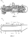
- the arrangement of an illustrative combustor 10 in a gas turbine engine 110 is shown in Fig. 1 .
- the gas turbine engine 110 includes an output shaft 120, a compressor 130, the combustor 10, and a turbine 150.
- the output shaft 120 is driven by the turbine 150 and may drive a propeller, a gearbox, a pump, or the like (not shown) depending on the application of the gas turbine engine 110.
- the compressor 130 compresses and delivers air to the combustor 10.
- the combustor 10 mixes fuel with the compressed air received from the compressor 130 and ignites the fuel.
- the hot, high pressure products of the combustion reaction in the combustor 10 are directed into the turbine 150 and the turbine 150 extracts work to drive the compressor 130 and the output shaft 120.
- the combustor is a can-type combustor assembly including a case 12, a liner 14 received in the case 12, and a cross key connection 26 coupling the liner 14 to the case 12 in Fig. 2 .
- the case 12 is coupled to an engine frame and supports the liner 14 in the engine frame.
- the liner 14 protects the case 12 from heat generated by the combustion reaction contained therein.
- the cross key connection 26 locates the liner 14 in an interior space 19 relative the case 12 without requiring fasteners that extend through parts of the liner 14 into an internal combustion cavity 22 of the liner 14.
- cooling holes may be machined or otherwise formed in the liner 14 to force pressurized cooling air to enter the combustion cavity 22.
- the case 12 includes a plurality of case cans 24 as shown in Fig. 1 .
- the case cans 24 are formed from a metallic material.
- Each can 24, has a generally longitudinal annular opening 15 to accommodate the liner 14 radially inward.
- Each can 24 has three or more threaded bosses 38 that form openings in the wall of the can 24 to form a portion of the cross key connection 26 with the liner 14.
- the liner 14 includes a plurality of liner cans 15 formed of a ceramic matrix composite material as shown in Fig. 2 .
- Each liner can 17 is formed to include a cylindrical hoop 16 and a dome-shaped end 18.
- Each hoop 16 is sized to fit radially inside the longitudinal annular opening 15 of a can 24 so that a channel 13 exists between the hoop 16 and the can 24.
- an opening 20 is formed in the domed-shaped proximal end 18 to accommodate a fuel nozzle 142.
- Hoop 16 is formed to further include three or more blind holes 36 to align with the three or more threaded bosses 38 in forming the cross key connections 26.
- the liner 14 and the casing 12 define an interior cylindrical space or cooling channel 13 therebetween. Heat is prevented from entering the proximal end of the cooling channel 13 via the domed proximal end 18 and opening 20 guiding the fuel nozzle 142 directly into a combustion chamber 22 within the liner 14.
- the liner is connected by a cross key connection 26 extending through the casing 12 and into the liner 14.
- Cross key connection 26 includes one or more pins 28 having a head 30 and a shank 34. Adjacent the head 30, a plurality of threads 32 are formed on a proximal end of the shank 34. Pins 28 extend through and threadingly engage the threaded bosses 38 via the threads 32 on shank. The distal end of the shank 34 of the pin 28, opposite the threads 32, is sized to fit into blind hole 36 of hoop 16.
- the pins 28 are sized to locate the hoop 16 radially inward and equidistant from a corresponding case can 24.
- Cross key connections 26 are equally spaced about the circumference of the can 24 to locate the hoop 16. Although three cross key connections 26 are illustrated in the embodiment, any number of cross key connections 26 that achieve the constant and equal spacing locating the hoop 16 inside the can 24 can be implemented.
- FIG. 5 Another illustrative combustor 210 adapted for use in the gas turbine engine 110 is show in in Fig. 5 .
- the combustor 210 is substantially similar to the combustor 10 show in in Figs. 1-4 described herein. Accordingly, similar reference numbers in the 200 series not specifically discussed herein indicate features that are common between combustor 10 and combustor 210.
- the description of the combustor 10 is hereby incorporated by reference to apply to the combustor 210 except in instances where it conflicts with the specific description and drawings of combustor 210.
- the combustor 210 includes case cans 224 that have an endcap 242 at a proximal end of the can 224 and the can liners 217 do not have a dome at a proximal end as shown in Fig. 5 . Rather the combustor 210 is configured to connect to fuel nozzles 142 via openings 244 in endcaps 242 of the case cans 224. Endcaps 242 are formed of the same metallic material as the case cans 224. Additionally, combustor 210 includes seal ring 240 fitted between the hoop 216 and the can 224. Seal ring 240 provides a seal between hoop 216, and can 224 and prevents heat from entering cooling channel 213. In some embodiments the seal ring 240 may be implemented by a ceramic piston seal.
- FIG. 6 Another illustrative combustor 310 adapted for use in the gas turbine engine 110 is show in in Fig. 6 .
- the combustor 310 is substantially similar to the combustor 10 show in in Figs. 1-4 described herein. Accordingly, similar reference numbers in the 300 series not specifically discussed herein indicate features that are common between combustor 10 and combustor 310.
- the description of the combustor 10 is hereby incorporated by reference to apply to the combustor 310 except in instances where it conflicts with the specific description and drawings of combustor 310.
- the combustor 310 includes a plurality of full hoops 346A, 346B, 346C included in each can liner 317.
- the first hoop 326A at a forward end of a can liner 317 is integrally formed with a dome-shaped proximal end 318 of the can liner 317.
- An opening 320 is formed in the domed-shaped proximal end 818 to accommodate a fuel nozzle 142.
- Hoops 346A 346B have sloped distal ends 347A-347B so that the distal end of each hoop nests in an adjacent hoop.
- each hoop may be spaced radially from each adjacent hoop by a predetermined distance so that cooling film may be pushed in through the space and distally along each adjacent hoop.
- Hoops 346A, 346B, 346C all are formed to have the same circumference at the cross key connection points where blind holes 336A-336C are formed to locate each hoop the same distance radially inward from the can 324.
- Case cans 324 have threaded bosses 338, spaced not only circumferentially, as shown in Fig. 3 , but also longitudinally along the case cans 324 to secure each hoop 346A, 346B, 346C inside the annular opening 315. Although illustratively depicted as three hoops, more or fewer hoops may be implemented.
- FIG. 7 Another illustrative combustor 410 adapted for use in the gas turbine engine 110 is show in in Fig. 7 .
- the combustor 410 is substantially similar to the combustor 10 show in in Figs. 1 and 5 described herein. Accordingly, similar reference numbers in the 300 series not discussed herein indicate features that are common between combustor 10 and combustor 410.
- the description of the combustor 10 is hereby incorporated by reference to apply to the combustor 410 except in instances where it conflicts with the specific description and drawings of combustor 410.
- Combustor 410 differs from combustor 10 in that it has a plurality of full hoops 448A, 448B, 448C included in each can liner 417.
- Combustor 410 is configured to connect to fuel nozzle 142 via opening 444 in an endcap 442 included in each case can 424. Endcaps 442 are formed of the same metallic material as the case cans 424.
- combustor 410 includes seal ring 440 fitted between the hoop 448A and the case can 424. Seal ring 440 prevents heat from entering channel 413 at the proximal end.
- Hoops 448A 448B have sloped distal ends 447A-447B so that the distal end of each hoop nests in an adjacent hoop.
- Hoops 448A, 448B, 448C all are formed to have the same circumference at the cross key connection points where the blind holes are formed to locate each hoop the same distance radially inward from the can 424.
- FIG. 8 An arrangement of another illustrative combustor 516 in a gas turbine engine 510 is shown in Fig. 8 .
- the combustor 516 is illustratively of the full-annular-type and includes a case 518, a liner 526, and a cross key connection 538.
- the liner 526 protects the metallic case 518 from heat generated by the combustion reaction contained therein.
- the cross key connection 538 locates the liner 526 in a radially interior space relative the case 518 without requiring fasteners that extend through parts of the liner into an internal combustion cavity of the liner 526.
- the case 518 illustratively comprises metallic materials and includes an outer annular wall 520 and an inner annular wall 522 that is generally concentric with and inside the outer annular wall 520 as shown in Fig. 9 .
- the outer annular wall 520 is coupled by a cross key connection 538 with the liner 526 as seen in Fig. 9 .
- the liner 526 comprises a ceramic matrix composite material and includes a radially inner annular wall 524 and an outer annular wall 528 defining an internal combustion cavity 533 therebetween.
- the inner and outer annular walls 524, 528 are connected at a proximal end via a domed ceramic surface 530.
- the liner 526 is sized to fit radially inside the opening formed between the inner and outer annular walls 520 522 of the case 518 so that inner radial channel 534 and outer radial channel 536 exist between the liner 526 and the case 518.
- An opening 532 is formed in the domed-shaped proximal end 18 to accommodate a fuel nozzle..
- cooling holes may be machined or otherwise formed in the liner 526 to force pressurized cooling air to enter the combustion cavity.
- Cross key connection 538 includes three or more pins 540 having a head 542 and a shank 546. Adjacent the head 542, a plurality of threads 544 are formed on a proximal end of the shank 546. Pins 540 are formed to extend through and threadingly engage a threaded boss 550 via the threads 544 on a pin 540. The distal end of the shank 546 of the pin 540, opposite the threads 544, is sized to fit into blind hole 548 of outer annular wall 528 of liner 526.
- the pins 540 are sized to locate the inner and outer annular liner walls 524, 528 radially inward the annular outer wall 520 of case 518 and radially outside the inner annular wall 522 of the case 518.
- Cross key connections 538 are equally spaced about the circumference of the outer annular wall 520 to locate the liner 514 Although three cross key connections 538 are illustrated in the embodiment, any number of cross key connections 538 that achieve the constant and equal spacing locating the liner 518 inside the outer annular wall 520 can be implemented. In this particular embodiment, no cross key connects are required to connect inner annular wall 522 of case and inner annular wall 524 of liner.
- FIG. 12 Another illustrative combustor 616 adapted for use in the gas turbine engine 510 is show in in Fig. 12 .
- the combustor 616 is substantially similar to the combustor 516 show in in Figs. 8-9 described herein. Accordingly, similar reference numbers in the 600 series not discussed herein indicate features that are common between combustor 516 and combustor 616.
- the description of the combustor 516 is hereby incorporated by reference to apply to the combustor 516 except in instances where it conflicts with the specific description and drawings of combustor 616.
- the combustor 616 includes a monolithic full annular inner hoop 624 and monolithic full annular outer hoop 628 that are not connected via domed ceramic surface at a proximal end forming the liner 526. Rather the combustor 616 is configured to connect to fuel nozzles via openings 656 in an endcap 658 of the case 518. Endcap 658 is formed of the same metallic material as the case 618. Additionally, combustor includes an inner seal ring 654 fitted between the inner annular liner hoop 624 and inner case wall 622, and an outer seal ring 652 fitted between the outer annular liner hoop 628 and outer annular case wall 620. Seal rings 654, 652 provide a seal between liner 626 and the case 618 and prevent heat from entering inner annular channel 634 and outer annular channel 636.
- both inner and outer case walls 620, 622 form cross key connections with the liner 526 since the inner and outer liner hoops 624, 628 are not connected.
- inner cross key connectors 638i will include threaded bosses 650i circumferentially spaced about the inner annular case wall 624 and inner blind holes 648i with threaded pins 640i extending through and threadingly engaging threaded bosses 650i and shanks extending into blind holes 648i of the inner annular hoop 624 to locate the inner annular hoop 624 radially outward relative to the inner annular case 622.
- FIG. 13 Another illustrative combustor case adapted for use in the gas turbine engine 510 is show in in Fig. 13 .
- the combustor 816 is substantially similar to the combustor 516 show in in Figs. 8-9 described herein. Accordingly, similar reference numbers in the 800 series not discussed below indicate features that are common between combustor 516 and combustor 816.
- the description of the combustor 516 is hereby incorporated by reference to apply to the combustor 816 except in instances where it conflicts with the specific description and drawings of combustor 816.
- the combustor 816 includes a plurality of outer full hoops 760A, 760B and a plurality of inner full hoops 762A 762B form the liner 626.
- the first outer and inner hoops 760A, 762A are joined at a forward end by a dome-shaped proximal end 730. Openings 756 are formed in the domed-shaped proximal end 730 to accommodate fuel nozzles.
- Inner and outer hoops 760A, 762A have sloped distal ends 761A, 763A so that the distal end of each hoop nests in an adjacent hoop.
- the sloped distal end of each hoop may be spaced radially from each adjacent hoop by a predetermined distance so that cooling film may be pushed in and distally along each adjacent hoop.
- Hoops 760A, 760B are formed to have the same circumference at the cross key connection points 738 where the blind holes 748 are formed to locate each hoop the same distance radially inward from the outer annular case wall 720.
- Inner hoop 762B is formed to have the same circumference at the cross key connection point 738i where the blind holes are formed to locate inner hoop 762B a distance radially outward from the inner annular case wall 722.
- Inner hoop 762A does not require a cross key connection with inner annular wall 722 as it is connected via the domed end 730 and therefore located via the cross key connection 738 at outer hoop 760A.
- more or fewer hoops may be implemented.
- FIG. 14 Another illustrative combustor 816 adapted for use in the gas turbine engine 510 is shown in Fig. 14 .
- the combustor 816 is substantially similar to the combustor 516 shown in Figs. 8 and 9 described herein. Accordingly, similar reference numbers in the 800 series not further discussed herein indicate features that are common between combustor 516 and combustor 816.
- the description of the 516 combustor is hereby incorporated by reference to apply to the combustor 816 except in instances where it conflicts with the specific description and drawings of combustor 816.
- Combustor 816 differs from combustor 516 in that it has a plurality of full outer hoops 866A, 866B and full inner hoops 864A, 864B forming the liner 814.
- Combustor 816 is configured to connect to fuel nozzles via openings 856 in an endcap 858 included in the case 818.
- Endcap 858 is formed of the same metallic material as the case 818.
- Inner and outer seal rings 854, 852 form a seal between outer annular case wall 820 and outer annular hoop 866A, and a seal between inner annular hoop 864A and inner annular case wall 822.
- Inner seal ring 854 and outer seal ring 852 provide a seal between liner 826 and the case 818 and prevent heat from entering inner annular channel 834 and outer annular channel 836.
- Inner and outer hoops 866A, 864A have sloped distal ends 865A, 867A so that the distal end of each hoop nests in an adjacent hoop.
Landscapes
- Engineering & Computer Science (AREA)
- Chemical & Material Sciences (AREA)
- Combustion & Propulsion (AREA)
- Mechanical Engineering (AREA)
- General Engineering & Computer Science (AREA)
- Ceramic Engineering (AREA)
- Turbine Rotor Nozzle Sealing (AREA)
Abstract
Description
- The present disclosure relates generally to combustors used in gas turbine engines, and more specifically to a combustor including a metallic case and a liner connected by cross key connectors.
- Engines, and particularly gas turbine engines, are used to power aircraft, watercraft, power generators and the like. Gas turbine engines typically include a compressor, a combustor, and a turbine. The compressor compresses air drawn into the engine and delivers high pressure air to the combustor. The combustor is a component or area of a gas turbine engine where combustion takes place. In a gas turbine engine, the combustor receives high pressure air and adds fuel to the air which is burned to produce hot, high-pressure gas. After burning the fuel, the hot, high-pressure gas is passed from the combustor to the turbine. The turbine extracts work from the hot, high-pressure gas to drive the compressor and residual energy is used for propulsion or sometimes to drive an output shaft.
- Combustors include liners that contain the combustion process during operation of a gas turbine engine. The liner included in the combustor is designed and built to withstand high-temperature cycles induced during combustion. In some cases, liners may be made from metallic superalloys. In other cases, liners may be made from ceramic matrix composites (CMCs) which are a subgroup of composite materials as well as a subgroup of technical ceramics. CMCs may comprise ceramic fibers embedded in a ceramic matrix. The matrix and fibers can consist of any ceramic material, whereby carbon and carbon fibers can also be considered a ceramic material.
- Combustors and turbines made of metal alloys often require significant cooling to be maintained at or below their maximum use temperatures. The operational efficiencies of gas turbine engines are sometimes increased with the use of CMC materials that require less cooling and have operating temperatures that exceed the maximum use temperatures of most metal alloys. The reduced cooling required by CMC combustor liners when compared to metal alloy combustion liners can permit greater temperature uniformity and thereby leads to reduced undesirable emissions.
- One challenge relating to the use of CMC liners is that they are sometimes secured to the surrounding metal shell via metal fasteners. Metal fasteners lose their strength and may even melt at CMC operating temperatures. Since the allowable operating temperature of a metal fastener is lower than the allowable operating temperature of the CMC, metal fasteners, and/or the area surrounding it, is often cooled to allow it to maintain its strength. Such a configuration may undermine the desired high temperature capability of the CMC. Accordingly, new techniques and configurations are needed for securely fastening liner material, such as CMC, to the walls of enclosures experiencing high-temperature environments.
- The present invention provides a combustor and method of assembling a combustor according to the appended claims.
- The present disclosure may comprise one or more of the following features and combinations thereof.
- A combustor assembly may include case comprising metallic materials adapted to be mounted in a gas turbine engine and formed to define an interior space a combustion liner comprising ceramic matrix composite materials arranged in the interior space of the case, and a plurality of pins. The combustion liner may be shaped to define a combustion chamber within the case and shield at least a portion of the case from the combustion chamber. The plurality of pins extend through the case and into blind holes formed in the combustion liner to provide cross key connections between the case and the combustion liner locating the combustion liner relative to the case.
- In some embodiments, the cross key connections are spaced circumferentially about the case to locate the combustion liner centrally within the case. Each of the plurality of pins includes a head that couples with the case and a shank that extends into the blind holes formed in the combustion liner. Each head may include threads configured to couple with bosses in the case.
- According to another aspect of the present disclosure, a method of assembling a combustor may include positioning a combustion liner comprising ceramic matrix composite materials/ in an interior space formed by a case comprising metallic material. The combustion liner may shaped to define a combustion chamber within the interior space and to shield at least a portion of the case from the combustion chamber. The method may further include establishing cross key connections between the combustion liner and the case by inserting a plurality of pins through the case and into the combustion liner. The combustion liner may be formed to include at least one full ceramic hoop including a plurality of blind holes radially spaced around the hoop for locating the hoop with the plurality of pins.
- These and other features of the present disclosure will become more apparent from the following description of the illustrative embodiments.
-
-
Fig. 1 is a perspective cut-away view of a turbine engine showing that the engine includes a can-type combustor assembly; -
Fig. 2 is a sectional view of a portion of the can-type combustor ofFig. 1 showing the combustor includes a ceramic domed liner mounted to a metallic case by cross key connectors; -
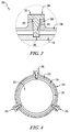
Fig. 3 is a zoomed in view of the connector ofFig. 2 that connects the ceramic liner to the metallic case; -
Fig. 4 is a cross-sectional view of the can-type combustor ofFig. 2 along the line 4-4. -
Fig. 5 is a sectional view of a portion of a second can-type combustor adapted for use in the turbine engine ofFig. 1 showing the combustor includes a ceramic liner, a metallic case, and a ceramic piston therebetween; -
Fig. 6 is a sectional view of a portion of a third can-type combustor adapted for use in the turbine engine ofFig. 1 showing the combustor includes a plurality of partially overlapping ceramic hoops, one hoop having a domed end, and a metallic case; -
Fig. 7 is a sectional view of a portion of a fourth can-type combustor adapted for use in the turbine engine ofFig. 1 showing the combustor includes a plurality of partially overlapping ceramic hoops and a metallic case; -
Fig. 8 is a perspective cut-away view of a turbine engine showing that the engine includes a full-annular-type combustor; -
Fig. 9 is a sectional view of the combustor ofFig. 8 , showing that the combustor includes a domed ceramic liner mounted to a metallic case by cross key connectors; -
Fig. 10 is a zoomed in view of the connector ofFig. 9 that connects the ceramic liner to the metallic case; -
Fig. 11 is a cross-sectional view of the combustor ofFig. 9 along the line 11-11; -
Fig. 12 is a sectional view of a second full-annular-type combustor adapted for use in the turbine engine ofFig. 8 showing a ceramic liner, a metallic case, and a ceramic ring seal therebetween; -
Fig. 13 is a sectional view of a third full-annular-type combustor adapted for use in the turbine engine ofFig. 8 showing the combustor includes a plurality of partially overlapping ceramic hoops, one hoop having a domed end, and a metallic case; and -
Fig. 14 is a sectional view of a fourth full-annular-type combustor adapted for use in the turbine engine ofFig. 8 showing the combustor includes a plurality of partially overlapping ceramic hoops and a metallic case. - For the purposes of promoting an understanding of the principles of the disclosure, reference will now be made to a number of illustrative embodiments illustrated in the drawings and specific language will be used to describe the same.
- The arrangement of an
illustrative combustor 10 in agas turbine engine 110 is shown inFig. 1 . Thegas turbine engine 110 includes anoutput shaft 120, acompressor 130, thecombustor 10, and aturbine 150. Theoutput shaft 120 is driven by theturbine 150 and may drive a propeller, a gearbox, a pump, or the like (not shown) depending on the application of thegas turbine engine 110. Thecompressor 130 compresses and delivers air to thecombustor 10. Thecombustor 10 mixes fuel with the compressed air received from thecompressor 130 and ignites the fuel. The hot, high pressure products of the combustion reaction in thecombustor 10 are directed into theturbine 150 and theturbine 150 extracts work to drive thecompressor 130 and theoutput shaft 120. - The combustor is a can-type combustor assembly including a
case 12, aliner 14 received in thecase 12, and across key connection 26 coupling theliner 14 to thecase 12 inFig. 2 . Thecase 12 is coupled to an engine frame and supports theliner 14 in the engine frame. Theliner 14 protects thecase 12 from heat generated by the combustion reaction contained therein. Thecross key connection 26 locates theliner 14 in aninterior space 19 relative thecase 12 without requiring fasteners that extend through parts of theliner 14 into aninternal combustion cavity 22 of theliner 14. In some embodiments, cooling holes (not shown) may be machined or otherwise formed in theliner 14 to force pressurized cooling air to enter thecombustion cavity 22. - The
case 12 includes a plurality ofcase cans 24 as shown inFig. 1 . Thecase cans 24 are formed from a metallic material. Each can 24, has a generally longitudinalannular opening 15 to accommodate theliner 14 radially inward. Each can 24 has three or more threadedbosses 38 that form openings in the wall of thecan 24 to form a portion of the crosskey connection 26 with theliner 14. - The
liner 14 includes a plurality ofliner cans 15 formed of a ceramic matrix composite material as shown inFig. 2 . Each liner can 17 is formed to include acylindrical hoop 16 and a dome-shapedend 18. Eachhoop 16 is sized to fit radially inside the longitudinalannular opening 15 of acan 24 so that achannel 13 exists between thehoop 16 and thecan 24. In the illustrative embodiment, anopening 20 is formed in the domed-shapedproximal end 18 to accommodate afuel nozzle 142.Hoop 16 is formed to further include three or moreblind holes 36 to align with the three or more threadedbosses 38 in forming the crosskey connections 26. - The
liner 14 and thecasing 12 define an interior cylindrical space or coolingchannel 13 therebetween. Heat is prevented from entering the proximal end of the coolingchannel 13 via the domedproximal end 18 andopening 20 guiding thefuel nozzle 142 directly into acombustion chamber 22 within theliner 14. The liner is connected by a crosskey connection 26 extending through thecasing 12 and into theliner 14. - Cross
key connection 26 includes one ormore pins 28 having ahead 30 and ashank 34. Adjacent thehead 30, a plurality ofthreads 32 are formed on a proximal end of theshank 34.Pins 28 extend through and threadingly engage the threadedbosses 38 via thethreads 32 on shank. The distal end of theshank 34 of thepin 28, opposite thethreads 32, is sized to fit intoblind hole 36 ofhoop 16. - As can be seen in
Fig. 3 , thepins 28 are sized to locate thehoop 16 radially inward and equidistant from a corresponding case can 24. Crosskey connections 26 are equally spaced about the circumference of thecan 24 to locate thehoop 16. Although three crosskey connections 26 are illustrated in the embodiment, any number of crosskey connections 26 that achieve the constant and equal spacing locating thehoop 16 inside thecan 24 can be implemented. - Another
illustrative combustor 210 adapted for use in thegas turbine engine 110 is show in inFig. 5 . Thecombustor 210 is substantially similar to thecombustor 10 show in inFigs. 1-4 described herein. Accordingly, similar reference numbers in the 200 series not specifically discussed herein indicate features that are common betweencombustor 10 andcombustor 210. The description of thecombustor 10 is hereby incorporated by reference to apply to thecombustor 210 except in instances where it conflicts with the specific description and drawings ofcombustor 210. - Unlike
combustor 10, thecombustor 210 includes case cans 224 that have anendcap 242 at a proximal end of the can 224 and thecan liners 217 do not have a dome at a proximal end as shown inFig. 5 . Rather thecombustor 210 is configured to connect to fuelnozzles 142 viaopenings 244 inendcaps 242 of the case cans 224.Endcaps 242 are formed of the same metallic material as the case cans 224. Additionally,combustor 210 includesseal ring 240 fitted between thehoop 216 and the can 224.Seal ring 240 provides a seal betweenhoop 216, and can 224 and prevents heat from enteringcooling channel 213. In some embodiments theseal ring 240 may be implemented by a ceramic piston seal. - Another
illustrative combustor 310 adapted for use in thegas turbine engine 110 is show in inFig. 6 . Thecombustor 310 is substantially similar to thecombustor 10 show in inFigs. 1-4 described herein. Accordingly, similar reference numbers in the 300 series not specifically discussed herein indicate features that are common betweencombustor 10 andcombustor 310. The description of thecombustor 10 is hereby incorporated by reference to apply to thecombustor 310 except in instances where it conflicts with the specific description and drawings ofcombustor 310. - Unlike
combustor 10, thecombustor 310 includes a plurality offull hoops liner 317. The first hoop 326A at a forward end of acan liner 317 is integrally formed with a dome-shapedproximal end 318 of thecan liner 317. Anopening 320 is formed in the domed-shaped proximal end 818 to accommodate afuel nozzle 142.Hoops 346AHoops blind holes 336A-336C are formed to locate each hoop the same distance radially inward from thecan 324.Case cans 324 have threaded bosses 338, spaced not only circumferentially, as shown inFig. 3 , but also longitudinally along thecase cans 324 to secure eachhoop - Another
illustrative combustor 410 adapted for use in thegas turbine engine 110 is show in inFig. 7 . Thecombustor 410 is substantially similar to thecombustor 10 show in inFigs. 1 and5 described herein. Accordingly, similar reference numbers in the 300 series not discussed herein indicate features that are common betweencombustor 10 andcombustor 410. The description of thecombustor 10 is hereby incorporated by reference to apply to thecombustor 410 except in instances where it conflicts with the specific description and drawings ofcombustor 410. -
Combustor 410 differs fromcombustor 10 in that it has a plurality offull hoops liner 417.Combustor 410 is configured to connect tofuel nozzle 142 via opening 444 in an endcap 442 included in each case can 424. Endcaps 442 are formed of the same metallic material as thecase cans 424. Additionally,combustor 410 includesseal ring 440 fitted between thehoop 448A and the case can 424.Seal ring 440 prevents heat from entering channel 413 at the proximal end.Hoops 448AHoops can 424. - An arrangement of another
illustrative combustor 516 in agas turbine engine 510 is shown inFig. 8 . Thecombustor 516 is illustratively of the full-annular-type and includes acase 518, aliner 526, and a crosskey connection 538. Theliner 526 protects themetallic case 518 from heat generated by the combustion reaction contained therein. The crosskey connection 538 locates theliner 526 in a radially interior space relative thecase 518 without requiring fasteners that extend through parts of the liner into an internal combustion cavity of theliner 526. - The
case 518 illustratively comprises metallic materials and includes an outerannular wall 520 and an innerannular wall 522 that is generally concentric with and inside the outerannular wall 520 as shown inFig. 9 . The outerannular wall 520 is coupled by a crosskey connection 538 with theliner 526 as seen inFig. 9 . - The
liner 526 comprises a ceramic matrix composite material and includes a radially innerannular wall 524 and an outerannular wall 528 defining aninternal combustion cavity 533 therebetween. The inner and outerannular walls ceramic surface 530. Theliner 526 is sized to fit radially inside the opening formed between the inner and outerannular walls 520 522 of thecase 518 so that innerradial channel 534 and outerradial channel 536 exist between theliner 526 and thecase 518. Anopening 532 is formed in the domed-shapedproximal end 18 to accommodate a fuel nozzle.. In some embodiments, cooling holes (not shown) may be machined or otherwise formed in theliner 526 to force pressurized cooling air to enter the combustion cavity. - Cross
key connection 538 includes three ormore pins 540 having ahead 542 and ashank 546. Adjacent thehead 542, a plurality ofthreads 544 are formed on a proximal end of theshank 546.Pins 540 are formed to extend through and threadingly engage a threadedboss 550 via thethreads 544 on apin 540. The distal end of theshank 546 of thepin 540, opposite thethreads 544, is sized to fit intoblind hole 548 of outerannular wall 528 ofliner 526. - As can be seen in
Fig. 11 , thepins 540 are sized to locate the inner and outerannular liner walls outer wall 520 ofcase 518 and radially outside the innerannular wall 522 of thecase 518. Crosskey connections 538 are equally spaced about the circumference of the outerannular wall 520 to locate theliner 514 Although three crosskey connections 538 are illustrated in the embodiment, any number of crosskey connections 538 that achieve the constant and equal spacing locating theliner 518 inside the outerannular wall 520 can be implemented. In this particular embodiment, no cross key connects are required to connect innerannular wall 522 of case and innerannular wall 524 of liner. This is due to the domedfront end 530 of liner connecting the inner and outerannular walls liner 526. Because of the domedfront end 530, the locating done by the crosskey connections 538 between outerannular wall 520 ofcase 518 and outerannular wall 528 ofliner 526 will provide corresponding locating between innerannular wall 522 of case 578 and inner annular wall ofliner 524. - Another
illustrative combustor 616 adapted for use in thegas turbine engine 510 is show in inFig. 12 . Thecombustor 616 is substantially similar to thecombustor 516 show in inFigs. 8-9 described herein. Accordingly, similar reference numbers in the 600 series not discussed herein indicate features that are common betweencombustor 516 andcombustor 616. The description of thecombustor 516 is hereby incorporated by reference to apply to thecombustor 516 except in instances where it conflicts with the specific description and drawings ofcombustor 616. - Unlike
combustor 516, thecombustor 616 includes a monolithic full annularinner hoop 624 and monolithic full annularouter hoop 628 that are not connected via domed ceramic surface at a proximal end forming theliner 526. Rather thecombustor 616 is configured to connect to fuel nozzles viaopenings 656 in anendcap 658 of thecase 518.Endcap 658 is formed of the same metallic material as thecase 618. Additionally, combustor includes aninner seal ring 654 fitted between the innerannular liner hoop 624 andinner case wall 622, and anouter seal ring 652 fitted between the outerannular liner hoop 628 and outerannular case wall 620. Seal rings 654, 652 provide a seal betweenliner 626 and thecase 618 and prevent heat from entering innerannular channel 634 and outerannular channel 636. - Additionally in this embodiment, both inner and
outer case walls liner 526 since the inner andouter liner hoops Fig. 10 , inner crosskey connectors 638i will include threaded bosses 650i circumferentially spaced about the innerannular case wall 624 and inner blind holes 648i with threaded pins 640i extending through and threadingly engaging threaded bosses 650i and shanks extending into blind holes 648i of the innerannular hoop 624 to locate the innerannular hoop 624 radially outward relative to the innerannular case 622. - Another illustrative combustor case adapted for use in the
gas turbine engine 510 is show in inFig. 13 . Thecombustor 816 is substantially similar to thecombustor 516 show in inFigs. 8-9 described herein. Accordingly, similar reference numbers in the 800 series not discussed below indicate features that are common betweencombustor 516 andcombustor 816. The description of thecombustor 516 is hereby incorporated by reference to apply to thecombustor 816 except in instances where it conflicts with the specific description and drawings ofcombustor 816. - Unlike
combustor 516, thecombustor 816 includes a plurality of outerfull hoops full hoops 762Aliner 626. The first outer andinner hoops proximal end 730.Openings 756 are formed in the domed-shapedproximal end 730 to accommodate fuel nozzles. Inner andouter hoops -
Hoops key connection points 738 where theblind holes 748 are formed to locate each hoop the same distance radially inward from the outerannular case wall 720.Inner hoop 762B is formed to have the same circumference at the crosskey connection point 738i where the blind holes are formed to locateinner hoop 762B a distance radially outward from the inner annular case wall 722.Inner hoop 762A does not require a cross key connection with inner annular wall 722 as it is connected via thedomed end 730 and therefore located via the crosskey connection 738 atouter hoop 760A. Although illustratively depicted as two hoops, more or fewer hoops may be implemented. - Another
illustrative combustor 816 adapted for use in thegas turbine engine 510 is shown inFig. 14 . Thecombustor 816 is substantially similar to thecombustor 516 shown inFigs. 8 and 9 described herein. Accordingly, similar reference numbers in the 800 series not further discussed herein indicate features that are common betweencombustor 516 andcombustor 816. The description of the 516 combustor is hereby incorporated by reference to apply to thecombustor 816 except in instances where it conflicts with the specific description and drawings ofcombustor 816. -
Combustor 816 differs fromcombustor 516 in that it has a plurality of fullouter hoops inner hoops Combustor 816 is configured to connect to fuel nozzles viaopenings 856 in anendcap 858 included in the case 818.Endcap 858 is formed of the same metallic material as the case 818. Inner and outer seal rings 854, 852 form a seal between outerannular case wall 820 and outerannular hoop 866A, and a seal between innerannular hoop 864A and innerannular case wall 822.Inner seal ring 854 andouter seal ring 852 provide a seal between liner 826 and the case 818 and prevent heat from entering inner annular channel 834 and outer annular channel 836. Inner andouter hoops - While the disclosure has been illustrated and described in detail in the foregoing drawings and description, the same is to be considered as exemplary and not restrictive in character, it being understood that only illustrative embodiments thereof have been shown and described and that all changes and modifications that come within the spirit of the disclosure are desired to be protected.
Claims (15)
- A combustor (10) for use in a gas turbine engine, the combustor comprising
a case (12) comprising metallic materials adapted to be mounted in a gas turbine engine and formed to define an interior space,
a combustion liner (14) comprising ceramic matrix composite materials arranged in the interior space of the case, the combustion liner shaped to define a combustion chamber within the case and shield at least a portion of the case from the combustion chamber, and
a plurality of pins (28) that extend through the case and into blind holes (36) formed in the combustion liner to provide cross key connections between the case and the combustion liner locating the combustion liner relative to the case. - The combustor of claim 1, the cross key connections are spaced circumferentially about the case to locate the combustion liner centrally within the case.
- The combustor of claim 2, wherein each of the plurality of pins includes a head (30) that couples with the case and a shank (34) that extends into the blind holes formed in the combustion liner.
- The combustor of claim 3, wherein each head includes threads (32) configured to couple with bosses (38) in the case.
- The combustor of claim 1, wherein the case comprises a plurality of cans and the combustion liner includes a plurality of can liners.
- The combustor of claim 5, wherein each can liner includes a cylindrical body, a domed front end (18), and a fuel entry aperture (20) formed through the domed front end.
- The combustor of claim 5, wherein a ceramic ring (654) forms a seal at a front end between each can and each can liner preventing heat from entering a cylindrical interior space between each can and can liner.
- The combustor as claimed in any of claims 5 to 7, wherein each can liner comprises a plurality of hoops (346A-C) that nest with each other such that the trailing edge of a first hoop overlaps the leading edge of an adjacent second hoop.
- The combustor of claim 1, wherein the case comprises a radially outer annular wall (620) and a radially inner annular wall (622) and the liner comprises an inner hoop (624) and an outer hoop (628) located in between the radially outer and inner annular walls.
- The combustor of claim 9 wherein the liner further comprises a domed front end (730) connecting the inner hoop (762A,B) and outer hoop (760A,B) and a plurality of fuel entry apertures (756) formed in the domed front end, wherein the liner and the radially inner and radially outer annular walls define radially inner and radially outer spaces therebetween.
- The combustor of either of claims 9 or 10, wherein the radially inner liner further comprises a plurality of hoops that nest with each other such that the trailing edge of a first hoop overlaps the leading edge of an adjacent second hoop, the radially outer liner comprises a plurality of hoops that nest with each other such that the trailing edge of a first hoop overlaps the leading edge of an adjacent second hoop.
- The combustor of any of claims 9 to 11, wherein cross key connections are established between the radially outer wall of the case and the outer hoop of the liner; and cross key connections are established between the radially inner wall of the case and the inner hoop of the liner.
- A method of assembling a combustor, the method comprising
positioning a combustion liner comprising ceramic matrix composite materials in an interior space formed by a case comprising metallic materials, the combustion liner shaped to define a combustion chamber within the interior space and to shield at least a portion of the case from the combustion chamber, and
establishing cross key connections between the combustion liner and the case by inserting a plurality of pins through the case and into the combustion liner. - The method of claim 13, wherein the combustion liner is formed to comprise at least one full ceramic hoop including a plurality of blindholes radially spaced around the hoop for locating the hoop with the plurality of pins.
- The method of either of claims 14 and 15, wherein the combustion liner comprises a smooth surfaced radially inner ceramic hoop and a radially outer ceramic hoop including radially spaced apart blind holes, the inner and outer ceramic hoops connected at an axially forward end via a domed front end; wherein the cross-key connections are established by inserting the plurality of pins into the blind holes on the outer ceramic hoop to locate the combustion liner in the case.
Applications Claiming Priority (1)
| Application Number | Priority Date | Filing Date | Title |
|---|---|---|---|
| US201562208338P | 2015-08-21 | 2015-08-21 |
Publications (1)
| Publication Number | Publication Date |
|---|---|
| EP3133346A1 true EP3133346A1 (en) | 2017-02-22 |
Family
ID=56551318
Family Applications (1)
| Application Number | Title | Priority Date | Filing Date |
|---|---|---|---|
| EP16181654.1A Withdrawn EP3133346A1 (en) | 2015-08-21 | 2016-07-28 | Case and liner arrangement for a combustor |
Country Status (2)
| Country | Link |
|---|---|
| US (1) | US10648669B2 (en) |
| EP (1) | EP3133346A1 (en) |
Families Citing this family (4)
| Publication number | Priority date | Publication date | Assignee | Title |
|---|---|---|---|---|
| EP3499125A1 (en) * | 2017-12-12 | 2019-06-19 | Siemens Aktiengesellschaft | Pipe combustion chamber with ceramic cladding |
| US11859818B2 (en) * | 2019-02-25 | 2024-01-02 | General Electric Company | Systems and methods for variable microchannel combustor liner cooling |
| DE102020203017A1 (en) | 2020-03-10 | 2021-09-16 | Siemens Aktiengesellschaft | Combustion chamber with ceramic heat shield and seal |
| US11859819B2 (en) | 2021-10-15 | 2024-01-02 | General Electric Company | Ceramic composite combustor dome and liners |
Citations (4)
| Publication number | Priority date | Publication date | Assignee | Title |
|---|---|---|---|---|
| EP0136071A1 (en) * | 1983-08-26 | 1985-04-03 | Westinghouse Electric Corporation | Varying thickness thermal barrier for combustion turbine baskets |
| US20090226279A1 (en) * | 2008-03-05 | 2009-09-10 | Jarmon David C | Internal pocket fastener system for ceramic matrix composites |
| US20120328366A1 (en) * | 2011-06-23 | 2012-12-27 | United Technologies Corporation | Methods for Joining Metallic and CMC Members |
| WO2015009384A1 (en) * | 2013-07-16 | 2015-01-22 | United Technologies Corporation | Gas turbine engine with ceramic panel |
Family Cites Families (28)
| Publication number | Priority date | Publication date | Assignee | Title |
|---|---|---|---|---|
| US2699648A (en) * | 1950-10-03 | 1955-01-18 | Gen Electric | Combustor sectional liner structure with annular inlet nozzles |
| US3911672A (en) * | 1974-04-05 | 1975-10-14 | Gen Motors Corp | Combustor with ceramic liner |
| US4109459A (en) * | 1974-07-19 | 1978-08-29 | General Electric Company | Double walled impingement cooled combustor |
| US5687572A (en) | 1992-11-02 | 1997-11-18 | Alliedsignal Inc. | Thin wall combustor with backside impingement cooling |
| US5291732A (en) | 1993-02-08 | 1994-03-08 | General Electric Company | Combustor liner support assembly |
| US5623827A (en) * | 1995-01-26 | 1997-04-29 | General Electric Company | Regenerative cooled dome assembly for a gas turbine engine combustor |
| US6904757B2 (en) * | 2002-12-20 | 2005-06-14 | General Electric Company | Mounting assembly for the forward end of a ceramic matrix composite liner in a gas turbine engine combustor |
| US6895761B2 (en) * | 2002-12-20 | 2005-05-24 | General Electric Company | Mounting assembly for the aft end of a ceramic matrix composite liner in a gas turbine engine combustor |
| US7093441B2 (en) | 2003-10-09 | 2006-08-22 | United Technologies Corporation | Gas turbine annular combustor having a first converging volume and a second converging volume, converging less gradually than the first converging volume |
| FR2871847B1 (en) | 2004-06-17 | 2006-09-29 | Snecma Moteurs Sa | MOUNTING A TURBINE DISPENSER ON A COMBUSTION CHAMBER WITH CMC WALLS IN A GAS TURBINE |
| US7464554B2 (en) | 2004-09-09 | 2008-12-16 | United Technologies Corporation | Gas turbine combustor heat shield panel or exhaust panel including a cooling device |
| US7647779B2 (en) * | 2005-04-27 | 2010-01-19 | United Technologies Corporation | Compliant metal support for ceramic combustor liner in a gas turbine engine |
| FR2897417A1 (en) | 2006-02-10 | 2007-08-17 | Snecma Sa | ANNULAR COMBUSTION CHAMBER OF A TURBOMACHINE |
| FR2897418B1 (en) | 2006-02-10 | 2013-03-01 | Snecma | ANNULAR COMBUSTION CHAMBER OF A TURBOMACHINE |
| US8863528B2 (en) * | 2006-07-27 | 2014-10-21 | United Technologies Corporation | Ceramic combustor can for a gas turbine engine |
| US8141370B2 (en) | 2006-08-08 | 2012-03-27 | General Electric Company | Methods and apparatus for radially compliant component mounting |
| US20090324393A1 (en) * | 2007-01-25 | 2009-12-31 | Siemens Power Generation, Inc. | Ceramic matrix composite turbine engine component |
| DE102007018061A1 (en) * | 2007-04-17 | 2008-10-23 | Rolls-Royce Deutschland Ltd & Co Kg | Gas turbine combustion chamber wall |
| US7908867B2 (en) | 2007-09-14 | 2011-03-22 | Siemens Energy, Inc. | Wavy CMC wall hybrid ceramic apparatus |
| GB0801839D0 (en) * | 2008-02-01 | 2008-03-05 | Rolls Royce Plc | combustion apparatus |
| US8307657B2 (en) * | 2009-03-10 | 2012-11-13 | General Electric Company | Combustor liner cooling system |
| US8745989B2 (en) | 2009-04-09 | 2014-06-10 | Pratt & Whitney Canada Corp. | Reverse flow ceramic matrix composite combustor |
| ES2531099T3 (en) * | 2009-06-09 | 2015-03-10 | Siemens Ag | Thermal shield element arrangement and procedure for mounting a thermal shield element |
| GB0913580D0 (en) * | 2009-08-05 | 2009-09-16 | Rolls Royce Plc | Combustor tile |
| CH703656A1 (en) * | 2010-08-27 | 2012-02-29 | Alstom Technology Ltd | From hot gases flowed through housing body with internal heat shield. |
| US8955331B2 (en) * | 2011-05-20 | 2015-02-17 | Siemens Energy, Inc. | Turbine combustion system coupling with adjustable wear pad |
| US9534783B2 (en) * | 2011-07-21 | 2017-01-03 | United Technologies Corporation | Insert adjacent to a heat shield element for a gas turbine engine combustor |
| WO2014137553A1 (en) * | 2013-03-06 | 2014-09-12 | United Technologies Coproration | Exhaust system having a flow path liner supported by structural duct segments |
-
2016
- 2016-07-20 US US15/214,865 patent/US10648669B2/en active Active
- 2016-07-28 EP EP16181654.1A patent/EP3133346A1/en not_active Withdrawn
Patent Citations (4)
| Publication number | Priority date | Publication date | Assignee | Title |
|---|---|---|---|---|
| EP0136071A1 (en) * | 1983-08-26 | 1985-04-03 | Westinghouse Electric Corporation | Varying thickness thermal barrier for combustion turbine baskets |
| US20090226279A1 (en) * | 2008-03-05 | 2009-09-10 | Jarmon David C | Internal pocket fastener system for ceramic matrix composites |
| US20120328366A1 (en) * | 2011-06-23 | 2012-12-27 | United Technologies Corporation | Methods for Joining Metallic and CMC Members |
| WO2015009384A1 (en) * | 2013-07-16 | 2015-01-22 | United Technologies Corporation | Gas turbine engine with ceramic panel |
Also Published As
| Publication number | Publication date |
|---|---|
| US20170051917A1 (en) | 2017-02-23 |
| US10648669B2 (en) | 2020-05-12 |
Similar Documents
| Publication | Publication Date | Title |
|---|---|---|
| US11274829B2 (en) | Shell and tiled liner arrangement for a combustor | |
| US9612017B2 (en) | Combustor with tiled liner | |
| US10024537B2 (en) | Combustor assembly with chutes | |
| EP1172611B1 (en) | Gas turbine combustor having dome-to-line joint | |
| US7086232B2 (en) | Multihole patch for combustor liner of a gas turbine engine | |
| US10648669B2 (en) | Case and liner arrangement for a combustor | |
| EP2538140B1 (en) | Reverse flow combustor duct attachment | |
| US11428410B2 (en) | Combustor for a gas turbine engine with ceramic matrix composite heat shield and seal retainer | |
| EP3315866B1 (en) | Combustor assembly with mounted auxiliary component | |
| JP2002031344A (en) | Modular combustor dome | |
| JP5178053B2 (en) | Method and apparatus for mounting radial compliant members | |
| US9696037B2 (en) | Liner retaining feature for a combustor | |
| EP1493971B1 (en) | Method for assembling gas turbine engine combustors | |
| US11466858B2 (en) | Combustor for a gas turbine engine with ceramic matrix composite sealing element | |
| EP3832206B1 (en) | Combustor for a gas turbine engine | |
| EP3730738A1 (en) | Turbine assembly for a gas turbine engine with ceramic matrix composite vane | |
| US9175855B2 (en) | Combustion nozzle with floating aft plate | |
| US11098901B2 (en) | Crossfire tube assembly with inner tube having different curvatures | |
| KR101842745B1 (en) | Connecting device of transition piece and turbine of gas turbine |
Legal Events
| Date | Code | Title | Description |
|---|---|---|---|
| PUAI | Public reference made under article 153(3) epc to a published international application that has entered the european phase |
Free format text: ORIGINAL CODE: 0009012 |
|
| STAA | Information on the status of an ep patent application or granted ep patent |
Free format text: STATUS: THE APPLICATION HAS BEEN PUBLISHED |
|
| AK | Designated contracting states |
Kind code of ref document: A1 Designated state(s): AL AT BE BG CH CY CZ DE DK EE ES FI FR GB GR HR HU IE IS IT LI LT LU LV MC MK MT NL NO PL PT RO RS SE SI SK SM TR |
|
| AX | Request for extension of the european patent |
Extension state: BA ME |
|
| STAA | Information on the status of an ep patent application or granted ep patent |
Free format text: STATUS: REQUEST FOR EXAMINATION WAS MADE |
|
| 17P | Request for examination filed |
Effective date: 20171127 |
|
| RBV | Designated contracting states (corrected) |
Designated state(s): AL AT BE BG CH CY CZ DE DK EE ES FI FR GB GR HR HU IE IS IT LI LT LU LV MC MK MT NL NO PL PT RO RS SE SI SK SM TR |
|
| STAA | Information on the status of an ep patent application or granted ep patent |
Free format text: STATUS: THE APPLICATION HAS BEEN WITHDRAWN |
|
| 18W | Application withdrawn |
Effective date: 20200701 |