EP3133279A1 - Method for manufacturing nozzle plate for fuel injection device, mold for nozzle plate for fuel injection device, and nozzle plate for fuel injection device - Google Patents
Method for manufacturing nozzle plate for fuel injection device, mold for nozzle plate for fuel injection device, and nozzle plate for fuel injection device Download PDFInfo
- Publication number
- EP3133279A1 EP3133279A1 EP15779737.4A EP15779737A EP3133279A1 EP 3133279 A1 EP3133279 A1 EP 3133279A1 EP 15779737 A EP15779737 A EP 15779737A EP 3133279 A1 EP3133279 A1 EP 3133279A1
- Authority
- EP
- European Patent Office
- Prior art keywords
- fuel injection
- nozzle
- cavity
- plate
- injection device
- Prior art date
- Legal status (The legal status is an assumption and is not a legal conclusion. Google has not performed a legal analysis and makes no representation as to the accuracy of the status listed.)
- Withdrawn
Links
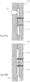
Images






Classifications
-
- F—MECHANICAL ENGINEERING; LIGHTING; HEATING; WEAPONS; BLASTING
- F02—COMBUSTION ENGINES; HOT-GAS OR COMBUSTION-PRODUCT ENGINE PLANTS
- F02M—SUPPLYING COMBUSTION ENGINES IN GENERAL WITH COMBUSTIBLE MIXTURES OR CONSTITUENTS THEREOF
- F02M61/00—Fuel-injectors not provided for in groups F02M39/00 - F02M57/00 or F02M67/00
- F02M61/16—Details not provided for in, or of interest apart from, the apparatus of groups F02M61/02 - F02M61/14
- F02M61/168—Assembling; Disassembling; Manufacturing; Adjusting
-
- B—PERFORMING OPERATIONS; TRANSPORTING
- B05—SPRAYING OR ATOMISING IN GENERAL; APPLYING FLUENT MATERIALS TO SURFACES, IN GENERAL
- B05B—SPRAYING APPARATUS; ATOMISING APPARATUS; NOZZLES
- B05B1/00—Nozzles, spray heads or other outlets, with or without auxiliary devices such as valves, heating means
- B05B1/14—Nozzles, spray heads or other outlets, with or without auxiliary devices such as valves, heating means with multiple outlet openings; with strainers in or outside the outlet opening
-
- B—PERFORMING OPERATIONS; TRANSPORTING
- B29—WORKING OF PLASTICS; WORKING OF SUBSTANCES IN A PLASTIC STATE IN GENERAL
- B29C—SHAPING OR JOINING OF PLASTICS; SHAPING OF MATERIAL IN A PLASTIC STATE, NOT OTHERWISE PROVIDED FOR; AFTER-TREATMENT OF THE SHAPED PRODUCTS, e.g. REPAIRING
- B29C45/00—Injection moulding, i.e. forcing the required volume of moulding material through a nozzle into a closed mould; Apparatus therefor
- B29C45/0046—Details relating to the filling pattern or flow paths or flow characteristics of moulding material in the mould cavity
-
- B—PERFORMING OPERATIONS; TRANSPORTING
- B29—WORKING OF PLASTICS; WORKING OF SUBSTANCES IN A PLASTIC STATE IN GENERAL
- B29C—SHAPING OR JOINING OF PLASTICS; SHAPING OF MATERIAL IN A PLASTIC STATE, NOT OTHERWISE PROVIDED FOR; AFTER-TREATMENT OF THE SHAPED PRODUCTS, e.g. REPAIRING
- B29C45/00—Injection moulding, i.e. forcing the required volume of moulding material through a nozzle into a closed mould; Apparatus therefor
- B29C45/17—Component parts, details or accessories; Auxiliary operations
- B29C45/26—Moulds
- B29C45/2628—Moulds with mould parts forming holes in or through the moulded article, e.g. for bearing cages
-
- F—MECHANICAL ENGINEERING; LIGHTING; HEATING; WEAPONS; BLASTING
- F02—COMBUSTION ENGINES; HOT-GAS OR COMBUSTION-PRODUCT ENGINE PLANTS
- F02M—SUPPLYING COMBUSTION ENGINES IN GENERAL WITH COMBUSTIBLE MIXTURES OR CONSTITUENTS THEREOF
- F02M61/00—Fuel-injectors not provided for in groups F02M39/00 - F02M57/00 or F02M67/00
- F02M61/16—Details not provided for in, or of interest apart from, the apparatus of groups F02M61/02 - F02M61/14
- F02M61/166—Selection of particular materials
-
- F—MECHANICAL ENGINEERING; LIGHTING; HEATING; WEAPONS; BLASTING
- F02—COMBUSTION ENGINES; HOT-GAS OR COMBUSTION-PRODUCT ENGINE PLANTS
- F02M—SUPPLYING COMBUSTION ENGINES IN GENERAL WITH COMBUSTIBLE MIXTURES OR CONSTITUENTS THEREOF
- F02M61/00—Fuel-injectors not provided for in groups F02M39/00 - F02M57/00 or F02M67/00
- F02M61/16—Details not provided for in, or of interest apart from, the apparatus of groups F02M61/02 - F02M61/14
- F02M61/18—Injection nozzles, e.g. having valve seats; Details of valve member seated ends, not otherwise provided for
- F02M61/1853—Orifice plates
-
- F—MECHANICAL ENGINEERING; LIGHTING; HEATING; WEAPONS; BLASTING
- F02—COMBUSTION ENGINES; HOT-GAS OR COMBUSTION-PRODUCT ENGINE PLANTS
- F02M—SUPPLYING COMBUSTION ENGINES IN GENERAL WITH COMBUSTIBLE MIXTURES OR CONSTITUENTS THEREOF
- F02M61/00—Fuel-injectors not provided for in groups F02M39/00 - F02M57/00 or F02M67/00
- F02M61/16—Details not provided for in, or of interest apart from, the apparatus of groups F02M61/02 - F02M61/14
- F02M61/18—Injection nozzles, e.g. having valve seats; Details of valve member seated ends, not otherwise provided for
- F02M61/1853—Orifice plates
- F02M61/186—Multi-layered orifice plates
-
- B—PERFORMING OPERATIONS; TRANSPORTING
- B29—WORKING OF PLASTICS; WORKING OF SUBSTANCES IN A PLASTIC STATE IN GENERAL
- B29L—INDEXING SCHEME ASSOCIATED WITH SUBCLASS B29C, RELATING TO PARTICULAR ARTICLES
- B29L2031/00—Other particular articles
- B29L2031/748—Machines or parts thereof not otherwise provided for
-
- F—MECHANICAL ENGINEERING; LIGHTING; HEATING; WEAPONS; BLASTING
- F02—COMBUSTION ENGINES; HOT-GAS OR COMBUSTION-PRODUCT ENGINE PLANTS
- F02M—SUPPLYING COMBUSTION ENGINES IN GENERAL WITH COMBUSTIBLE MIXTURES OR CONSTITUENTS THEREOF
- F02M2200/00—Details of fuel-injection apparatus, not otherwise provided for
- F02M2200/80—Fuel injection apparatus manufacture, repair or assembly
- F02M2200/8046—Fuel injection apparatus manufacture, repair or assembly the manufacture involving injection moulding, e.g. of plastic or metal
-
- F—MECHANICAL ENGINEERING; LIGHTING; HEATING; WEAPONS; BLASTING
- F02—COMBUSTION ENGINES; HOT-GAS OR COMBUSTION-PRODUCT ENGINE PLANTS
- F02M—SUPPLYING COMBUSTION ENGINES IN GENERAL WITH COMBUSTIBLE MIXTURES OR CONSTITUENTS THEREOF
- F02M2200/00—Details of fuel-injection apparatus, not otherwise provided for
- F02M2200/80—Fuel injection apparatus manufacture, repair or assembly
- F02M2200/8069—Fuel injection apparatus manufacture, repair or assembly involving removal of material from the fuel apparatus, e.g. by punching, hydro-erosion or mechanical operation
-
- F—MECHANICAL ENGINEERING; LIGHTING; HEATING; WEAPONS; BLASTING
- F02—COMBUSTION ENGINES; HOT-GAS OR COMBUSTION-PRODUCT ENGINE PLANTS
- F02M—SUPPLYING COMBUSTION ENGINES IN GENERAL WITH COMBUSTIBLE MIXTURES OR CONSTITUENTS THEREOF
- F02M2200/00—Details of fuel-injection apparatus, not otherwise provided for
- F02M2200/90—Selection of particular materials
- F02M2200/9015—Elastomeric or plastic materials
Definitions
- the present invention relates to a manufacturing method for a fuel injection device nozzle plate (abbreviated below as a nozzle plate as appropriate), attached to the fuel injection port of a fuel injection device, that atomizes and injects fuel flowing from the fuel injection port, a die for the nozzle plate, and the nozzle plate.
- a fuel injection device nozzle plate abbreviated below as a nozzle plate as appropriate
- An internal combustion engine (abbreviated below as an engine) of an automobile or the like mixes fuel injected from a fuel injection device and air introduced via an intake pipe to generate a combustible gas mixture and burns the combustible gas mixture in the cylinder. It is known that the mixture state of fuel injected from the fuel injection device and air significantly affects the performance of this type of engine and, in particular, the atomization of fuel injected from the fuel injection device is an important factor governing the performance of the engine.
- a nozzle plate is attached to the fuel injection port of a valve body and fuel is injected through a plurality of fine nozzle holes formed in the nozzle plate (see PTL 1 and PTL 2). It is known that it is important to set the ratio (d/t) of a hole diameter d of the nozzle holes to a thickness t of the nozzle plate to a particular range for atomization of fuel particles in spray in such a nozzle plate (see PTL 3).
- the hole diameter d of the nozzle holes is often set to a value from 0.1 mm to 0.3 mm and the thickness (length of the nozzle holes) t of the nozzle plate is often set to a value from 0.1 mm to 0.2 mm.
- the conventional nozzle plate described above has a plurality of fine nozzle holes in a metal thin plate and is fixed to a metal valve body by welding, so the nozzle holes and the vicinity thereof are easily damaged when the fuel injection device is conveyed or attached to an engine.
- a fuel injection device 100 having the structure as illustrated in Fig. 14 has been developed.
- a resin or metal sleeve 104 for protecting nozzle holes 103 of the nozzle plate 101 and the vicinity thereof is attached to the end of a valve body 102 to which a the nozzle plate 101 is fixed (see PTL 5).
- a resin nozzle plate obtained by integrating the nozzle plate 101 with the sleeve 104 illustrated in Fig. 14 and attach this resin nozzle plate to the end of the valve body 102.
- Fig. 15 illustrates such a resin nozzle plate 105.
- the nozzle plate 105 illustrated in Fig. 15 includes the cylindrical fitting part 106 fixed to the outer periphery of the front end side of the valve body and a plate body part 107 formed in a disc shape so as to block one end side of the cylindrical fitting part 106.
- the plate body part 107 of the nozzle plate 105 is disposed facing the fuel injection port of the valve body, a plurality of thin plate portions 108 are formed at regular intervals around a central axis 110 of the nozzle plate 105, and nozzle holes 111 are formed in the thin plate portions 108.
- Fig. 16 is a cross sectional view illustrating a die 112 used for injection molding of the nozzle plate 105.
- a cavity 113 of the die 112 mainly includes a first cavity portion 114 for forming the plate body part 107 and a second cavity portion 115 for forming the cylindrical fitting part 106.
- a gate 116 is opened to a cavity portion for forming a portion thicker than the thin plate portion 108.
- the opening position of the gate 116 close to the cavity 113 is the position (first gate opening position in Fig. 16(a) ) in the first cavity portion 114 close to the second cavity portion 115, the position (second gate opening position in Fig. 16(b) ) in the first cavity portion 114 radially inward of the first gate opening position and radially outward of the portion for forming the thin plate portion 108, the position (third gate opening position in Fig. 16(c) ) in the second cavity portion 115 close to the first cavity portion 114, or the position (fourth gate opening position in Fig. 16(d) ) in the second cavity portion 115 away from the first cavity portion 114.
- Nozzle hole formation pins 117 for forming the nozzle holes 111 project into the cavity 113.
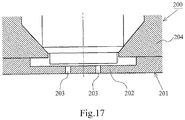
- Fig. 17 is a cross sectional view illustrating the front end side of a fuel injection device 200 to which a nozzle plate 201 according to conventional example 2 is attached.
- the nozzle plate 201 according to conventional example 2 is provided with a plurality of nozzle holes 203 in a thin plate portion 202, which is a metal plate member, and is fixed to the end of a metal valve body 204 by welding (see PTL 6).
- substitution of resin is considered for the same purpose as in the nozzle plate 101 according to conventional example 1.
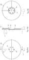
- Fig. 18 illustrates a resin nozzle plate 205 for which substitution for the metal nozzle plate 201 is considered.
- the nozzle plate 205 in Fig. 18 is formed in a disc shape, provided with a thin plate portion 206 formed by denting the rear surface of the central part like a truncated cone, and provided with a plurality of nozzle holes 207 in the thin plate portion 206.
- Fig. 19 is a cross sectional view illustrating a die 208 used for injection molding of the nozzle plate 205.
- a gate 211 is opened to a cavity portion for forming a portion thicker than the thin plate portion 206.
- the opening position of the gate 211 close to the cavity 210 is the position (first gate opening position in Fig.
- Nozzle hole formation pins 212 for forming the nozzle holes 207 project into the cavity 210.
- molten resin does not easily flow into the thin plate portion 108 or 206 (vicinity of the nozzle holes 111 or 207) in which the thickness is significantly reduced and there is delay in filling the cavity portion for forming the plurality of nozzle holes 111 or 207 and the vicinity thereof with molten resin. Accordingly, it becomes difficult to accurately form the nozzle holes 111 or 207 and the vicinity thereof and a molding failure such as gas burning easily occurs in the vicinity of the nozzle holes 111 or 207 distant from the gate 116 or 211.
- the invention provides a manufacturing method for a nozzle plate that can accurately mold nozzle holes and the vicinity thereof and does not cause a molding failure easily, a die for the nozzle plate, and the nozzle plate.
- the invention relates to a manufacturing method for a fuel injection device nozzle plate 1 including a plate body part 11 disposed facing a fuel injection port 6 of a fuel injection device 4, one thin plate portion or a plurality of thin plate portions 16, 34, or 37 of the plate body part 11 provided with a plurality of nozzle holes 7 through which fuel injected from the fuel injection port 6 passes, and a thick-walled portion 17, 35, or 41 formed at a position in the plate body part 11 at which the thin plate portions 16, 34, or 37 are surrounded, as illustrated in Fig 1 to Fig. 13 .
- a cavity portion for forming a portion surrounded by the plurality of nozzle holes 7 is provided with a gate 3 for injecting molten resin into the cavity 21.
- the molten resin injected from the gate 3 into the cavity 21 flows radially toward portions for forming the nozzle holes 7.
- the invention relates to a die 2 for a fuel injection device nozzle plate 1 including a plate body part 11 disposed facing a fuel injection port 6 of a fuel injection device 4, one thin plate portion or a plurality of thin plate portions 16, 34, or 37 of the plate body part 11 provided with a plurality of nozzle holes 7 through which fuel injected from the fuel injection port 6 passes, and a thick-walled portion 17, 35, or 41 formed at a position in the plate body part 11 at which the thin plate portions 16, 34, or 37 are surrounded, as illustrated in Fig 1 to Fig. 13 .
- a cavity portion for forming a portion surrounded by the plurality of nozzle holes 7 is provided with a gate 3 for injecting molten resin into the cavity 21.
- the molten resin injected from the gate 3 into the cavity 21 flows radially toward portions for forming the nozzle holes 7.
- the invention relates to a fuel injection device nozzle plate 1 including a plate body part 11 disposed facing a fuel injection port 6 of a fuel injection device 4, one thin plate portion or a plurality of thin plate portions 16, 34, or 37 of the plate body part 11 provided with a plurality of nozzle holes 7 through which fuel injected from the fuel injection port 6 passes, and a thick-walled portion 17, 35, or 41 formed at a position in the plate body part 11 at which the thin plate portions 16, 34, or 37 are surrounded, as illustrated in Fig 1 to Fig. 13 .
- the fuel injection device nozzle plate 1 according to the invention is formed by injecting molten resin from a gate 3 into a cavity 21 for a die, and a cut-off mark of the gate 3 is positioned in a portion surrounded by the plurality of nozzle holes 7.
- the invention by suppressing differences in the formation times (the charge times of molten resin) of a plurality of nozzle holes significantly affecting spray characteristics, a molding failure of the nozzle holes and the vicinity thereof can be prevented and the shapes of the nozzle holes and the vicinity thereof can be formed accurately.
- Fig. 1 illustrates the relationship between the nozzle plate 1 and the gate 3 for injection molding.
- Fig. 2 is a cross sectional view illustrating the die 2 for the nozzle plate 1.
- the nozzle plate 1 formed by injection molding is attached to the end of a valve body 5 of the fuel injection device 4 and sprays fuel injected from the fuel injection port 6 of the valve body 5 through a plurality of (six in the embodiment) nozzle holes 7 toward an intake pipe 8.
- This nozzle plate 7 is a bottomed cylindrical body, made of synthetic resin material (for example, PPS, PEEK, POM, PA, PES, PEI, or LCP), that includes a cylindrical fitting part 10 and the plate body part 11 formed integrally with one end side of the cylindrical fitting part 10.
- This nozzle plate 7 is fixed to the valve body 5 in the state in which the cylindrical fitting part 10 is fitted onto the outer periphery of the front end side of the valve body 5 without any space and an inner plane 12 of the plate body part 11 abuts against a front end surface 13 of the valve body 5.
- the plate body part 11 is formed in a disc shape and the plurality of nozzle holes 7 are formed at regular intervals around a central axis 14.
- the nozzle holes 7 are formed at the centers of the thin discoid plate portions 16 positioned at the bottom of nozzle hole formation concave portions 15 formed by, for example, countersinking the plate body part 11 like a truncated cone shape.
- the thick-walled portion 17 is formed so as to surround the thin plate portions 16 and the thick-walled portion 17 reinforces the thin plate portions 16.
- the thick-walled portion 17 is formed to approximately 0.5 mm when the wall thickness of the thin plate portions 16 is 0.1 mm.
- the nozzle holes 7 are circular holes passing through the front and rear of the thin plate portions 16 and formed to have a diameter of 0.2 mm when the wall thickness of the thin plate portions 16 is 0.1 mm.
- the dimensions of the thick-walled portion 17, the thin plate portions 16, and the nozzle holes 7 are only examples for facilitating the understanding of the invention and may be appropriate values for atomization of fuel fine particles in spray.
- the cylindrical fitting part 10 formed integrally with the plate body part 11 is formed to have a wall thickness larger than the plate body part 11.
- the cavity 21 is formed between a first die 18 and a second die 20 and nozzle hole formation pins 22 for forming the nozzle holes 7 project into the cavity 21.
- the ends of nozzle hole formation pins 22 abut against a cavity inner plane 23 of the first die 18.
- the portions of the first die 18 against which the nozzle hole formation pins 22 abut are convexities 24 for forming the nozzle hole formation concave portions 15.
- the cavity 21 includes a first cavity portion 25 for forming the plate body part 11 and a second cavity portion 26 for forming the cylindrical fitting part 10. At the center of the first cavity portion 25, the gate 3 for injecting molten resin into the cavity 21 is opened.
- the center of an opening 27 of the gate 3 is positioned in a central axis 28 of the cavity 21 and positioned equidistantly from the centers (the centers of the nozzle hole formation pins 22) of the plurality of nozzle holes 7 (see Figs. 1 (a) and 1 (b) ).
- the molten resin when molten resin is injected from the gate 3 into the cavity 21, then the molten resin flows through the cavity 21 radially, the molten resin concurrently reaches the portions (the cavity portion surrounding the plurality of nozzle hole formation pins 22) of the first cavity portion 25 that form the plurality of nozzle holes 7, the cavity portion (25) surrounding the plurality of nozzle hole formation pins 22 is filled with the molten resin, the molten resin evenly flows concentrically toward the radially outward end of the first cavity portion 25, and the second cavity portion 26 is filled with the molten resin.
- the cavity portion (25) for forming the thin plate portions 16 and the nozzle holes 7 is positioned in the vicinity of the gate 3 and the injection pressure and the dwell pressure are applied evenly and surely to the cavity portion (25) that forms the thin plate portions 16 and the nozzle holes 7, the shapes of the nozzle holes 7 and the vicinity thereof are formed accurately.
- the cut-off mark (gate mark) of the gate 3 is formed at the center (position equidistant from the centers of the nozzle holes 7) of the plate body part 11.
- the plurality of nozzle holes 7 significantly affecting spray characteristics are formed concurrently, a molding failure caused by differences in the formation times (the charge times of molten resin) of the nozzle holes 7 can be prevented, and the shapes of the nozzle holes 7 and the vicinity thereof can be formed accurately.
- FIG. 3 illustrates the relationship between the nozzle plate 1 and the gate 3 for injection molding.
- Fig. 4 is a cross sectional view illustrating the die 2 for the nozzle plate 1.
- components corresponding to those in Fig. 1 and Fig. 2 illustrating the first embodiment are given the same reference numerals to omit duplicate descriptions as in the first embodiment above as appropriate.
- the nozzle plate 7 according to the modification does not have the cylindrical fitting part 10 of the nozzle plate 7 according to the first embodiment and only has the component corresponding to the plate body part 11 of the nozzle plate 7 according to the first embodiment.
- the nozzle plate 7 according to the modification is fixed to the valve body 5 in the state in which the inner plane 12 of the plate body part 11 is in contact with the front end surface 13 of the valve body 5 as in the nozzle plate 7 according to the first embodiment.
- the cavity 21 is formed between the first die 18 and the second die 20 and the nozzle hole formation pins 22 for forming the nozzle holes 7 project into the cavity 21.
- the ends of the nozzle hole formation pins 22 abut against the cavity inner plane 23 of the first die 18.
- the portions of the first die 18 against which the nozzle hole formation pins 22 abut are the convexities 24 for forming the nozzle hole formation concave portions 15.
- the cavity 21 is the same as the cavity 21 of the die 2 according to the first embodiment except the second cavity portion 26 and corresponds to the first cavity portion 25 of the cavity 21 for the die according to the first embodiment.
- the gate 3 for injecting molten resin into the cavity 21 is opened.
- the center of the opening 27 of the gate 3 is positioned in the central axis 28 of the cavity 21 and positioned equidistantly from the centers (the centers of the nozzle hole formation pins 22) of the plurality of nozzle holes 7 (see Figs. 3(a) and 3(b) ).
- the molten resin when molten resin is injected from the gate 3 into the cavity 21, then the molten resin flows through the cavity 21 radially, the molten resin concurrently reaches the portions (the cavity portion surrounding the plurality of nozzle hole formation pins 22) in the cavity 21 that form the plurality of nozzle holes 7, the cavity portion surrounding the plurality of nozzle hole formation pins 22 is filled with the molten resin, the molten resin evenly flows concentrically toward the radially outward end of the first cavity 21, and the entire cavity 21 is filled with the molten resin.
- the cavity portion for forming the thin plate portions 16 and the nozzle holes 7 is positioned in the vicinity of the gate 3 and the injection pressure and the dwell pressure are applied evenly and surely to the cavity portion for forming the thin plate portions 16 and the nozzle holes 7, the shapes of the nozzle holes 7 and the vicinity thereof are formed accurately.
- the cut-off mark (gate mark) of the gate 3 is formed at the center (position equidistant from the centers of the nozzle holes 7) of the plate body part 11.
- Fig. 5 illustrates modification 2 of the nozzle plate 1, the manufacturing method for the nozzle plate 1, and the die 2 for the nozzle plate 1 according to the first embodiment and this drawing corresponds to Fig. 1(a) .
- Fig. 6 illustrates modification 3 of the nozzle plate 1, the manufacturing method for the nozzle plate 1, and the die 2 for the nozzle plate 1 according to the first embodiment and this drawing corresponds to Fig. 1(a) .
- the center of the opening 27 to the cavity is positioned in the central axis (the central axis 14 of the nozzle plate 1) of the cavity and the center of the opening 27 to the cavity is positioned equidistantly from the centers (the centers of the nozzle hole formation pins) of the nozzle holes 7.
- the modification described above can obtain the same effects as in the first embodiment described above.
- Fig. 7 illustrates the relationship between the nozzle plate 1 according to the embodiment and the gate 3 for injection molding.
- Fig. 8 is a cross sectional view illustrating the die 2 for the nozzle plate 1 according to the embodiment.
- the nozzle plate 1 formed by injection molding is a bottomed cylindrical body, made of synthetic resin (for example, PPS, PEEK, POM, PA, PES, PEI, or LCP), that includes the cylindrical fitting part 10 and the plate body part 11 formed integrally with one end side of the cylindrical fitting part 10, as in the nozzle plate 1 according to the first embodiment.
- synthetic resin for example, PPS, PEEK, POM, PA, PES, PEI, or LCP
- the plate body part 11 is formed in a disc shape and the plurality of nozzle holes 7 are formed at regular intervals around the central axis 14.
- the nozzle holes 7 are formed in a thin plate portion 34 positioned at the bottom of nozzle hole formation concave portions 33 formed by, for example, countersinking the plate body part 11 like a hollow disc shape.
- a thick-walled portion 35 is formed so as to surround the thin plate portion 34 and the thick-walled portion 35 reinforces the thin plate portion 34.
- the wall thickness of the thin plate portion 34, the wall thickness of the thick-walled portion 35, and the diameter of the nozzle holes 7 are determined in the same way as in the nozzle plate 1 according to the first embodiment described above.
- the cavity 21 is formed between the first die 18 and the second die 20 and the nozzle hole formation pins 22 for forming the nozzle holes 7 project into the cavity 21.
- the ends of the nozzle hole formation pins 22 abut against the cavity inner plane 23 of the first die 18.
- the portions of the first die 18 against which the nozzle hole formation pins 22 abut are convexities 36 for forming the nozzle hole formation concave portions 33 shaped like a hollow disc.
- the cavity 21 includes the first cavity portion 25 for forming the plate body part 11 and the second cavity portion 26 for forming the cylindrical fitting part 10.
- the gate 3 for injecting molten resin into the cavity 21 is opened.
- the center of the opening 27 of the gate 3 is positioned in the central axis 28 of the cavity 21 and positioned equidistantly from the centers (the centers of the nozzle hole formation pins 22) of the plurality of nozzle holes 7 (see Figs. 7(a) and 7(b) ).
- the molten resin when molten resin is injected from the gate 3 into the cavity 21, then the molten resin flows through the cavity 21 radially, the molten resin concurrently reaches the portions (the cavity portion surrounding the plurality of nozzle hole formation pins 22) of the first cavity portion 25 that form the plurality of nozzle holes 7, the cavity portion surrounding the plurality of nozzle hole formation pins 22 is filled with the molten resin, the molten resin evenly flows toward the radially outward end of the plate body part 11, and the second cavity portion 26 is filled with the molten resin.
- the cut-off mark (gate mark) of the gate 3 is formed in the part of a thick-walled gate base 29 surrounded by the thin plate portion 34, the part being at the center (the position equidistant from the centers of the nozzle holes 7) of the plate body part 11.
- the gate base 29 has the same wall thickness as the thick-walled portion 35 of the plate body part 11 to obtain the strength enduring a force applied when the gate 3 is separated from the nozzle plate 1 so that the periphery of the gate 3 is not torn and broken when the gate 3 is separated (see Fig. 7 ).
- a cavity portion 29a for forming the gate base 29 has a capacity large enough to store molten resin for forming the thin plate portion 34 of the plate body part 11 (see Fig. 8 ).
- the gate base 29 may be thicker than the thick-walled portion 35 of the plate body part 11 to obtain the strength enduring the force applied during separation of the gate 3.
- the gate base 29 may be thinner than the thick-walled portion 35 of the plate body part 11 as long as the gate base 29 has a strength enduring the force applied during separation of the gate 3.
- the plurality of nozzle holes 7 significantly affecting spray characteristics are formed concurrently, a molding failure caused by differences in the formation times (the charge times of molten resin) of the nozzle holes 7 can be prevented, and the shapes of the nozzle holes 7 and the vicinity thereof can be formed accurately.
- Fig. 9 illustrates the relationship between the nozzle plate 1 according to the embodiment and the gate 3 for injection molding.
- Fig. 10(a) is an enlarged view illustrating a part of Fig. 9(a) .
- Fig. 10(b) is a cross sectional view taken along line A5-A5 in Fig. 10(a) .
- Fig. 11 is a cross sectional view illustrating the die 2 for the nozzle plate 1 according to the embodiment.
- the nozzle plate 1 formed by injection molding includes the cylindrical fitting part 10 and the plate body part 11 formed so as to block one end side of the cylindrical fitting part 10, as in the nozzle plates 1 according to the first and second embodiments.
- the plate body part 11 includes thin plate portions 37 (nozzle hole plate portions) in which the nozzles hole 7 are formed, an interference body plate portion 40 in which three interference bodies 38 are formed, and a thick-walled portion 41 positioned so as to surround the thin plate portions 37 and the interference body plate portion 40.
- the interference body plate portion 40 is formed by denting the part around the central axis 14 of the plate body part 11 like a hollow disc.
- the thin plate portions 37 are formed by, for example, partially countersinking the part of the interference body plate portion 40 around the nozzle holes 7 and the thin plate portions 37 are thinner than the interference body plate portion 40.
- the plurality of nozzle holes 7 and the plurality of thin plate portions 37 are formed at regular intervals around the central axis 14 and parts of the nozzle holes 7 pass through (are opened to the front and rear) the front and rear of the thin plate portions 37.
- the interference bodies 38 blocking parts of the nozzle holes 7 are formed in the interference body plate portion 40.
- the interference bodies 38 formed in the interference body plate portion 40 partially blocks the nozzle holes 7 to form orifices 42.
- the interference body 38 has a collision surface 43 with which a part of fuel passing through the nozzle hole 7 collides. A flow of fuel passing through the nozzle hole 7 is disturbed by colliding with the collision surface 43 of the interference body 38.
- a side surface (inclined plane) 44 connecting the outer surface of the thin plate portions 37 to the outer surface of the interference body plate portion 40 is positioned away from an outlet side opening 45 of the nozzle hole 7 equidistantly from of the outlet side opening 45 of the nozzle hole 7 opened to the thin plate portions 37 so as not to interfere with spray injected from the nozzle hole 7.
- a side surface (inclined plane) 46 connecting the outer surface of the interference body plate portion 40 to the outer surface of the thick-walled portion 41 is formed so as not to interfere with spray injected from the nozzle hole 7.
- the thin plate portions 37, the nozzle holes 7, and the interference bodies 38 of the nozzle plate 1 are disposed radially around the central axis 14 of the nozzle plate 1.
- the cavity 21 is formed between the first die 18 and the second die 20 and the nozzle hole formation pins 22 for forming the nozzle holes 7 project into the cavity 21.
- the ends of nozzle hole formation pins 22 abut against the cavity inner plane 23 of the first die 18.
- the portions of the first die 18 against which the nozzle hole formation pins 22 abut are convexities 47 for forming and the contours of the thin plate portions 37 and the interference bodies 38.
- the cavity 21 includes the first cavity portion 25 for forming the plate body part 11 and the second cavity portion 26 for forming the cylindrical fitting part 10. At the center of the first cavity portion 25, the gate 3 for injecting molten resin into the cavity 21 is opened.
- the center of the opening 27 of the gate 3 is positioned in the central axis 28 of the cavity 21 and positioned equidistantly from the centers (the centers of the nozzle hole formation pins 22) of the plurality of nozzle holes 7 (see Figs. 9(a) and 9(b) ).
- the molten resin when molten resin is injected from the gate 3 into the cavity 21, then the molten resin flows through the cavity 21 radially, the molten resin concurrently reaches the part (the cavity portion surrounding the plurality of nozzle hole formation pins 22) of the first cavity portion 25 in which the plurality of nozzle holes 7 are formed, the cavity portion surrounding the plurality of nozzle hole formation pins 22 is filled with the molten resin, the molten resin evenly flows toward the radially outward end of the plate body part 11, and the second cavity portion 26 is filled with the molten resin.
- the cut-off mark (gate mark) of the gate 3 is formed in the part of the thick-walled gate base 29 surrounded by the interference body plate portion 40, the part being at the center (the position equidistant from the centers of the nozzle holes 7) of the plate body part 11.
- the gate base 29 has the same wall thickness as the thick-walled portion 41 of the plate body part 11 to obtain the strength enduring a force applied when the gate 3 is separated from the nozzle plate 1 so that the periphery of the gate 3 is not torn and broken when the gate 3 is separated (see Fig. 9 ).
- the cavity portion 29a for forming the gate base 29 has a capacity large enough to store molten resin for forming the vicinity of the nozzle holes 7 of the plate body part 11 (see Fig. 11 ).
- the gate base 29 may be thicker than the thick-walled portion 41 of the plate body part 11 to obtain the strength enduring the force applied during separation of the gate 3.
- the gate base 29 may be thinner than the thick-walled portion 41 of the plate body part 11 as long as the gate base 29 has a strength enduring the force applied during separation of the gate 3.
- the plurality of nozzle holes 7 significantly affecting spray characteristics are formed concurrently, a molding failure caused by differences in the formation times (the charge times of molten resin) of the nozzle holes 7 can be prevented, and the shapes of the nozzle holes 7 and the vicinity thereof can be formed accurately.
- the shapes of the nozzle holes 7 and the vicinity thereof can be formed accurately as described above. Therefore, corner portions 50 formed between arc-shaped outer edge parts 48 of the interference bodies 38 and the outlet side opening 45 of the nozzle hole 7 and corner portions 51 formed between the interference bodies 38 and the interference bodies 38 are formed in an acute shape without roundness.
- the nozzle plate 1 formed by the manufacturing method and the die 2 according to the embodiment can make the end of a liquid film of fuel passing through the orifice 42 sharp so that the fuel is easily atomized by friction with air and can promote the atomization of fuel fine particles in spray.
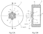
- Fig. 12 illustrates the relationship between the nozzle plate 1 according to the fourth embodiment of the invention and the gate 3 for injection molding and illustrates the nozzle plate 1 formed by changing a part of the die.
- Fig. 12 illustrates a modification of the first embodiment and components common to those in the first embodiment in Fig. 1 are given the same reference numerals to omit duplicate descriptions as in the first embodiment.
- a raised portion 52 is formed in the portion (the portion on a surface 11 a of the plate body part 11 equidistant from the plurality of nozzle holes 7) of the nozzle plate 1 in which the gate 3 is disposed and then the raised portion 52 formed projecting from the surface 11 a of the plate body part 11 is ground after injection molding to remove the gate mark.
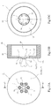
- Fig. 13 illustrates the relationship between the nozzle plate 1 according to the fifth embodiment of the invention and the gate 3 for injection molding and illustrates a modification of the nozzle plate 1 according to the fourth embodiment.
- Fig. 13 illustrates a modification of the fourth embodiment and components common to those in the fourth embodiment in Fig. 12 are given the same reference numerals to omit duplicate descriptions as in the fourth embodiment.
- nozzle plate 1 As illustrated in Fig. 13 , in the nozzle plate 1 according to the embodiment, as many first nozzle hole formation concave portions 15 as the nozzle holes 7 are formed in the surface 11 a of the plate body part 11 and a second nozzle hole formation concave portion 53 dented like a truncated cone is formed in the central part on the back surface (inner plane 12) of the plate body part 11 to form the plurality of thin plate portions 16 between the bottoms of the first nozzle hole formation concave portions 15 and the bottom of the second nozzle hole formation concave portion 53.
- the nozzle holes 7 pass through the front and rear of the thin plate portions 16. The embodiment described above can obtain the same effects as in the first embodiment.
- the nozzle plate 1 according to the invention is not limited to the above embodiments in which the cut-off mark of the gate 3 is positioned equidistantly from the centers of the plurality of nozzle holes 7.
- the invention is not limited to the manufacturing methods according to the above embodiments in which the nozzle plate 1 is manufactured using the die 2 having the gate 3 positioned equidistantly from the centers of the plurality of nozzle holes 7 (gate formation pins 22).
- the cut-off mark of the gate 3 does not need to be positioned equidistantly from the centers of the plurality of nozzle holes as long as the cut-off mark of the gate 3 is formed in the part of the plate body part 11, the part being surrounded by the plurality of nozzle holes 7.
- the gate 3 is not equidistant from the centers of the plurality of nozzle holes 7 (the nozzle hole formation pins 22), if the gate 3 is disposed in the cavity portion (in the plate body part 11) for forming the portion surrounded by the plurality of nozzle holes 7, it is possible to reduce the differences in the times required for molten resin to reach the cavity portions (cavity portions into which the nozzle hole formation pins 22 project) for forming the nozzle holes 7 in the cavity 21 as compared with comparative examples 1 and 2.
- the molten resin injected from the gate 3 into the cavity 21 flows radially outward of the cavity 21, fills the cavity portion for forming the nozzle holes 7 and the thin plate portions in the vicinity thereof, flows further radially outward of the cavity 21, and fills the entire cavity 21.
- the differences in the distances from the centers of the plurality of nozzle holes 7 to the center of the gate 3 are preferably as small as possible to minimize the differences in the times required for molten resin to reach the cavity portions for forming the nozzle holes from the gate 3.
Landscapes
- Engineering & Computer Science (AREA)
- Mechanical Engineering (AREA)
- Chemical & Material Sciences (AREA)
- Combustion & Propulsion (AREA)
- General Engineering & Computer Science (AREA)
- Manufacturing & Machinery (AREA)
- Moulds For Moulding Plastics Or The Like (AREA)
- Fuel-Injection Apparatus (AREA)
- Injection Moulding Of Plastics Or The Like (AREA)
Abstract
Description
- The present invention relates to a manufacturing method for a fuel injection device nozzle plate (abbreviated below as a nozzle plate as appropriate), attached to the fuel injection port of a fuel injection device, that atomizes and injects fuel flowing from the fuel injection port, a die for the nozzle plate, and the nozzle plate.
- An internal combustion engine (abbreviated below as an engine) of an automobile or the like mixes fuel injected from a fuel injection device and air introduced via an intake pipe to generate a combustible gas mixture and burns the combustible gas mixture in the cylinder. It is known that the mixture state of fuel injected from the fuel injection device and air significantly affects the performance of this type of engine and, in particular, the atomization of fuel injected from the fuel injection device is an important factor governing the performance of the engine.
- In such a fuel injection device, in order to atomize fuel in spray, a nozzle plate is attached to the fuel injection port of a valve body and fuel is injected through a plurality of fine nozzle holes formed in the nozzle plate (see
PTL 1 and PTL 2). It is known that it is important to set the ratio (d/t) of a hole diameter d of the nozzle holes to a thickness t of the nozzle plate to a particular range for atomization of fuel particles in spray in such a nozzle plate (see PTL 3). The hole diameter d of the nozzle holes is often set to a value from 0.1 mm to 0.3 mm and the thickness (length of the nozzle holes) t of the nozzle plate is often set to a value from 0.1 mm to 0.2 mm. - In addition, there is a known fuel injection device nozzle plate in which a swirl chamber is formed in the surface facing the fuel injection port of a valve body by, for example, carving so that fuel injected from the fuel injection port is guided to nozzle holes via the swirl chamber, rotating force is given to the fuel in the swirl chamber, the fuel having received the rotating force is injected from the nozzle holes, and the fuel is atomized (see PTL 4).
- The conventional nozzle plate described above has a plurality of fine nozzle holes in a metal thin plate and is fixed to a metal valve body by welding, so the nozzle holes and the vicinity thereof are easily damaged when the fuel injection device is conveyed or attached to an engine. To solve such a problem, a
fuel injection device 100 having the structure as illustrated inFig. 14 has been developed. In thefuel injection device 100 illustrated inFig. 14 , a resin ormetal sleeve 104 for protectingnozzle holes 103 of thenozzle plate 101 and the vicinity thereof is attached to the end of avalve body 102 to which a thenozzle plate 101 is fixed (see PTL 5). - In recent years, in a fuel injection device to be attached to a port injection engine, for reduction in the manufacturing cost and reduction in the size and weight, it is considered to form (injection-mold) a resin nozzle plate obtained by integrating the
nozzle plate 101 with thesleeve 104 illustrated inFig. 14 and attach this resin nozzle plate to the end of thevalve body 102.Fig. 15 illustrates such aresin nozzle plate 105. - The
nozzle plate 105 illustrated inFig. 15 includes thecylindrical fitting part 106 fixed to the outer periphery of the front end side of the valve body and aplate body part 107 formed in a disc shape so as to block one end side of thecylindrical fitting part 106. Theplate body part 107 of thenozzle plate 105 is disposed facing the fuel injection port of the valve body, a plurality ofthin plate portions 108 are formed at regular intervals around acentral axis 110 of thenozzle plate 105, andnozzle holes 111 are formed in thethin plate portions 108. -
Fig. 16 is a cross sectional view illustrating a die 112 used for injection molding of thenozzle plate 105. As illustrated inFig. 16 , a cavity 113 of thedie 112 mainly includes afirst cavity portion 114 for forming theplate body part 107 and asecond cavity portion 115 for forming thecylindrical fitting part 106. Then, in thedie 112, since the injection pressure needs to be kept at the last stage of the injection molding process so that resin injected into the cavity 113 fills every corner of the cavity 113 and the dwell pressure needs to be applied to improve the accuracy of thenozzle plate 105 to be molded, agate 116 is opened to a cavity portion for forming a portion thicker than thethin plate portion 108. For example, the opening position of thegate 116 close to the cavity 113 is the position (first gate opening position inFig. 16(a) ) in thefirst cavity portion 114 close to thesecond cavity portion 115, the position (second gate opening position inFig. 16(b) ) in thefirst cavity portion 114 radially inward of the first gate opening position and radially outward of the portion for forming thethin plate portion 108, the position (third gate opening position inFig. 16(c) ) in thesecond cavity portion 115 close to thefirst cavity portion 114, or the position (fourth gate opening position inFig. 16(d) ) in thesecond cavity portion 115 away from thefirst cavity portion 114. Nozzlehole formation pins 117 for forming thenozzle holes 111 project into the cavity 113. -
Fig. 17 is a cross sectional view illustrating the front end side of afuel injection device 200 to which anozzle plate 201 according to conventional example 2 is attached. Thenozzle plate 201 according to conventional example 2 is provided with a plurality ofnozzle holes 203 in athin plate portion 202, which is a metal plate member, and is fixed to the end of ametal valve body 204 by welding (see PTL 6). In thenozzle plate 201 according to conventional example 2, substitution of resin is considered for the same purpose as in thenozzle plate 101 according to conventional example 1. -
Fig. 18 illustrates aresin nozzle plate 205 for which substitution for themetal nozzle plate 201 is considered. Thenozzle plate 205 inFig. 18 is formed in a disc shape, provided with athin plate portion 206 formed by denting the rear surface of the central part like a truncated cone, and provided with a plurality ofnozzle holes 207 in thethin plate portion 206. -
Fig. 19 is a cross sectional view illustrating a die 208 used for injection molding of thenozzle plate 205. As illustrated inFig. 19 , in thedie 208, since the injection pressure needs to be kept at the last stage of the injection molding process so that resin injected into thecavity 210 fills every corner of thecavity 210 and the dwell pressure needs to be applied to improve the accuracy of thenozzle plate 205 to be molded, agate 211 is opened to a cavity portion for forming a portion thicker than thethin plate portion 206. For example, the opening position of thegate 211 close to thecavity 210 is the position (first gate opening position inFig. 19(a) ) in the middle in the radial direction of the cavity portion of thecavity 210 for forming the thick-walled portion of thenozzle plate 205 or the position (second gate opening position inFig. 19(b) ) on the side surface at the outer end in the radial direction of thecavity 210. Nozzlehole formation pins 212 for forming thenozzle holes 207 project into thecavity 210. -
- PTL 1:
-
JP-A-2000-45913 - PTL 2:
-
JP-A-2005-207274 - PTL 3:
-
Japanese Patent No. 4097056 - PTL 4:
-
JP-A-2012-215135 - PTL 5:
-
JP-A-2004-211552 - PTL 6:
-
JP-A-2002-115628 - However, when the
nozzle plate Fig. 16 orFig. 19 , molten resin does not easily flow into thethin plate portion 108 or 206 (vicinity of thenozzle holes 111 or 207) in which the thickness is significantly reduced and there is delay in filling the cavity portion for forming the plurality ofnozzle holes nozzle holes nozzle holes gate - Therefore, the invention provides a manufacturing method for a nozzle plate that can accurately mold nozzle holes and the vicinity thereof and does not cause a molding failure easily, a die for the nozzle plate, and the nozzle plate.
- The invention relates to a manufacturing method for a fuel injection
device nozzle plate 1 including aplate body part 11 disposed facing afuel injection port 6 of afuel injection device 4, one thin plate portion or a plurality ofthin plate portions plate body part 11 provided with a plurality ofnozzle holes 7 through which fuel injected from thefuel injection port 6 passes, and a thick-walled portion plate body part 11 at which thethin plate portions Fig 1 to Fig. 13 . In the invention, of acavity 21 for forming theplate body part 11, a cavity portion for forming a portion surrounded by the plurality ofnozzle holes 7 is provided with agate 3 for injecting molten resin into thecavity 21. The molten resin injected from thegate 3 into thecavity 21 flows radially toward portions for forming thenozzle holes 7. - In addition, the invention relates to a
die 2 for a fuel injectiondevice nozzle plate 1 including aplate body part 11 disposed facing afuel injection port 6 of afuel injection device 4, one thin plate portion or a plurality ofthin plate portions plate body part 11 provided with a plurality ofnozzle holes 7 through which fuel injected from thefuel injection port 6 passes, and a thick-walledportion plate body part 11 at which thethin plate portions Fig 1 to Fig. 13 . In the invention, of acavity 21 for forming theplate body part 11, a cavity portion for forming a portion surrounded by the plurality ofnozzle holes 7 is provided with agate 3 for injecting molten resin into thecavity 21. The molten resin injected from thegate 3 into thecavity 21 flows radially toward portions for forming thenozzle holes 7. - In addition, the invention relates to a fuel injection
device nozzle plate 1 including aplate body part 11 disposed facing afuel injection port 6 of afuel injection device 4, one thin plate portion or a plurality ofthin plate portions plate body part 11 provided with a plurality ofnozzle holes 7 through which fuel injected from thefuel injection port 6 passes, and a thick-walled portion plate body part 11 at which thethin plate portions Fig 1 to Fig. 13 . The fuel injectiondevice nozzle plate 1 according to the invention is formed by injecting molten resin from agate 3 into acavity 21 for a die, and a cut-off mark of thegate 3 is positioned in a portion surrounded by the plurality ofnozzle holes 7. - According to the invention, by suppressing differences in the formation times (the charge times of molten resin) of a plurality of nozzle holes significantly affecting spray characteristics, a molding failure of the nozzle holes and the vicinity thereof can be prevented and the shapes of the nozzle holes and the vicinity thereof can be formed accurately.
-
- [
Fig. 1] Fig. 1 illustrates the relationship between a nozzle plate formed by a manufacturing method and a die according to a first embodiment of the invention and a gate position.Fig. 1 (a) illustrates the gate position on the front side of the nozzle plate,Fig. 1 (b) illustrates the gate position in a cross section of the nozzle plate taken along line A1-A1 inFig. 1(a), and Fig. 1(c) is a back view illustrating the fuel injection device nozzle plate. - [
Fig. 2] Fig. 2 is a cross sectional view illustrating the die according to the first embodiment of the invention. - [
Fig. 3] Fig. 3 illustratesmodification 1 of the first embodiment and illustrates the relationship between a nozzle plate formed by a manufacturing method and a die according tomodification 1 and a gate position.Fig. 3(a) illustrates the gate position on the front side of the nozzle plate,Fig. 3(b) illustrates the gate position in a cross section of the nozzle plate taken along line A2-A2 inFig. 3(a), and Fig. 3(c) is a back view illustrating the nozzle plate. - [
Fig. 4] Fig. 4 is a cross sectional view illustrating the die according tomodification 1 of the first embodiment. - [
Fig. 5] Fig. 5 illustrates the relationship between a nozzle plate formed by a manufacturing method and a die according tomodification 2 of the first embodiment and a gate position and this drawing corresponds toFig. 1(a) . - [
Fig. 6] Fig. 6 illustrates the relationship between a nozzle plate formed by a manufacturing method and a die according tomodification 3 of the first embodiment and a gate position and this drawing corresponds toFig. 1(a) . - [
Fig. 7] Fig. 7 illustrates the relationship between a fuel injection device nozzle plate formed by a manufacturing method and a die according to a second embodiment of the invention and a gate position.Fig. 7(a) illustrates the gate position on the front side of the fuel injection device nozzle plate,Fig. 7(b) illustrates the gate position in a cross section of the fuel injection device nozzle plate taken along line A3-A3 inFig. 7(a), and Fig. 7(c) is a back view illustrating the fuel injection device nozzle plate. - [
Fig. 8] Fig. 8 is a cross sectional view illustrating the die according to the second embodiment of the invention. - [
Fig. 9] Fig. 9 illustrates the relationship between a fuel injection device nozzle plate formed by a manufacturing method and a die according to a third embodiment of the invention and a gate position.Fig. 9(a) illustrates the gate position on the front side of the fuel injection device nozzle plate,Fig. 9(b) illustrates the gate position in a cross sectional view of the fuel injection device nozzle plate taken along line A4-A4 inFig. 9(a), and Fig. 9(c) is a back view illustrating the fuel injection device nozzle plate. - [
Fig. 10] Fig. 10(a) is an enlarged view illustrating a part ofFig. 9(a) andFig. 10(b) is a cross sectional view taken along line A5-A5 inFig. 10(a) . - [
Fig. 11] Fig. 11 is a cross sectional view illustrating the die according to the third embodiment of the invention. - [
Fig. 12] Fig. 12 illustrates the fourth embodiment of the invention.Fig. 12(a) illustrates a gate position on the front side of a fuel injection device nozzle plate andFig. 12(b) illustrates the gate position in a cross sectional view of the fuel injection device nozzle plate taken along line A6-A6 inFig. 12(a) . - [
Fig. 13] Fig. 13 illustrates a fifth embodiment of the invention.Fig. 13(a) illustrates a gate position on the front side of a fuel injection device nozzle plate,Fig. 13(b) illustrates the gate position in a cross sectional view of the fuel injection device nozzle plate taken along line A7-A7 inFig. 13(a), and Fig. 13(c) is a back view illustrating the fuel injection device nozzle plate. - [
Fig. 14] Fig. 14 is a cross sectional view illustrating the front end side of a fuel injection device to which a nozzle plate according to a conventional example 1 has been attached. - [
Fig. 15] Fig. 15(a) illustrates a gate position on the front side of a nozzle plate according to a comparative example 1,Fig. 15(b) illustrates the gate position in a cross section of the nozzle plate taken along line A8-A8 inFig. 15(a), and Fig. 15(c) illustrates the gate position seen from the back side of the nozzle plate. - [
Fig. 16] Fig. 16 is a cross sectional view illustrating a die used for the injection molding of the nozzle plate according to the comparative example 1 illustrated inFig. 15 . - [
Fig. 17] Fig. 17 is a cross sectional view illustrating the front end side of a fuel injection device to which a nozzle plate according to conventional example 2 has been attached. - [
Fig. 18] Fig. 18(a) illustrates a gate position on the front side of the nozzle plate according to conventional example 2,Fig. 18(b) illustrates the gate position in a cross section of the nozzle plate taken along line A9-A9 inFig. 18(a), and Fig. 18(c) illustrates the gate position seen from the back side of the nozzle plate. - [
Fig. 19] Fig. 19 is a cross sectional view illustrating a die used for the injection molding of the nozzle plate according to comparative example 2 illustrated inFig. 18 . - Embodiments of the invention will be described in detail below with reference to the drawings.
- The fuel injection device nozzle plate 1 (abbreviated below as the nozzle plate) according to the first embodiment of the invention, the manufacturing method for the
nozzle plate 1, and thedie 2 for thenozzle plate 1 will be described in detail with reference toFig. 1 andFig. 2 .Fig. 1 illustrates the relationship between thenozzle plate 1 and thegate 3 for injection molding. In addition,Fig. 2 is a cross sectional view illustrating thedie 2 for thenozzle plate 1. - As illustrated in
Fig. 1 , thenozzle plate 1 formed by injection molding is attached to the end of avalve body 5 of thefuel injection device 4 and sprays fuel injected from thefuel injection port 6 of thevalve body 5 through a plurality of (six in the embodiment) nozzle holes 7 toward anintake pipe 8. Thisnozzle plate 7 is a bottomed cylindrical body, made of synthetic resin material (for example, PPS, PEEK, POM, PA, PES, PEI, or LCP), that includes a cylindricalfitting part 10 and theplate body part 11 formed integrally with one end side of the cylindricalfitting part 10. Thisnozzle plate 7 is fixed to thevalve body 5 in the state in which the cylindricalfitting part 10 is fitted onto the outer periphery of the front end side of thevalve body 5 without any space and aninner plane 12 of theplate body part 11 abuts against afront end surface 13 of thevalve body 5. - The
plate body part 11 is formed in a disc shape and the plurality ofnozzle holes 7 are formed at regular intervals around acentral axis 14. The nozzle holes 7 are formed at the centers of the thindiscoid plate portions 16 positioned at the bottom of nozzle hole formationconcave portions 15 formed by, for example, countersinking theplate body part 11 like a truncated cone shape. In theplate body part 11, the thick-walled portion 17 is formed so as to surround thethin plate portions 16 and the thick-walled portion 17 reinforces thethin plate portions 16. The thick-walled portion 17 is formed to approximately 0.5 mm when the wall thickness of thethin plate portions 16 is 0.1 mm. The nozzle holes 7 are circular holes passing through the front and rear of thethin plate portions 16 and formed to have a diameter of 0.2 mm when the wall thickness of thethin plate portions 16 is 0.1 mm. However, the dimensions of the thick-walled portion 17, thethin plate portions 16, and the nozzle holes 7 are only examples for facilitating the understanding of the invention and may be appropriate values for atomization of fuel fine particles in spray. In addition, the cylindricalfitting part 10 formed integrally with theplate body part 11 is formed to have a wall thickness larger than theplate body part 11. - In the
die 2 illustrated inFig. 2 , thecavity 21 is formed between afirst die 18 and asecond die 20 and nozzle hole formation pins 22 for forming the nozzle holes 7 project into thecavity 21. The ends of nozzle hole formation pins 22 abut against a cavityinner plane 23 of thefirst die 18. The portions of thefirst die 18 against which the nozzle hole formation pins 22 abut are convexities 24 for forming the nozzle hole formationconcave portions 15. Thecavity 21 includes afirst cavity portion 25 for forming theplate body part 11 and asecond cavity portion 26 for forming the cylindricalfitting part 10. At the center of thefirst cavity portion 25, thegate 3 for injecting molten resin into thecavity 21 is opened. The center of anopening 27 of thegate 3 is positioned in acentral axis 28 of thecavity 21 and positioned equidistantly from the centers (the centers of the nozzle hole formation pins 22) of the plurality of nozzle holes 7 (seeFigs. 1 (a) and 1 (b) ). - In the
die 2 described above, when molten resin is injected from thegate 3 into thecavity 21, then the molten resin flows through thecavity 21 radially, the molten resin concurrently reaches the portions (the cavity portion surrounding the plurality of nozzle hole formation pins 22) of thefirst cavity portion 25 that form the plurality ofnozzle holes 7, the cavity portion (25) surrounding the plurality of nozzle hole formation pins 22 is filled with the molten resin, the molten resin evenly flows concentrically toward the radially outward end of thefirst cavity portion 25, and thesecond cavity portion 26 is filled with the molten resin. In addition, in thedie 2 according to the embodiment, since the cavity portion (25) for forming thethin plate portions 16 and the nozzle holes 7 is positioned in the vicinity of thegate 3 and the injection pressure and the dwell pressure are applied evenly and surely to the cavity portion (25) that forms thethin plate portions 16 and the nozzle holes 7, the shapes of the nozzle holes 7 and the vicinity thereof are formed accurately. In thenozzle plate 1 after injection molding, the cut-off mark (gate mark) of thegate 3 is formed at the center (position equidistant from the centers of the nozzle holes 7) of theplate body part 11. - In the manufacturing method and the
die 2 for thenozzle plate 1 according to the embodiment described above, the plurality ofnozzle holes 7 significantly affecting spray characteristics are formed concurrently, a molding failure caused by differences in the formation times (the charge times of molten resin) of the nozzle holes 7 can be prevented, and the shapes of the nozzle holes 7 and the vicinity thereof can be formed accurately. - A modification of the
nozzle plate 1, the manufacturing method for thenozzle plate 1, and thedie 2 for thenozzle plate 1 according to the first embodiment will be described in detail with reference toFig. 3 andFig. 4 .Fig. 3 illustrates the relationship between thenozzle plate 1 and thegate 3 for injection molding. In addition,Fig. 4 is a cross sectional view illustrating thedie 2 for thenozzle plate 1. InFig. 3 andFig. 4 illustrating the modification, components corresponding to those inFig. 1 andFig. 2 illustrating the first embodiment are given the same reference numerals to omit duplicate descriptions as in the first embodiment above as appropriate. - The
nozzle plate 7 according to the modification does not have the cylindricalfitting part 10 of thenozzle plate 7 according to the first embodiment and only has the component corresponding to theplate body part 11 of thenozzle plate 7 according to the first embodiment. Thenozzle plate 7 according to the modification is fixed to thevalve body 5 in the state in which theinner plane 12 of theplate body part 11 is in contact with thefront end surface 13 of thevalve body 5 as in thenozzle plate 7 according to the first embodiment. - In the
die 2 illustrated inFig. 4 , thecavity 21 is formed between thefirst die 18 and thesecond die 20 and the nozzle hole formation pins 22 for forming the nozzle holes 7 project into thecavity 21. The ends of the nozzle hole formation pins 22 abut against the cavityinner plane 23 of thefirst die 18. The portions of thefirst die 18 against which the nozzle hole formation pins 22 abut are theconvexities 24 for forming the nozzle hole formationconcave portions 15. Thecavity 21 is the same as thecavity 21 of thedie 2 according to the first embodiment except thesecond cavity portion 26 and corresponds to thefirst cavity portion 25 of thecavity 21 for the die according to the first embodiment. At the center of thecavity 21, thegate 3 for injecting molten resin into thecavity 21 is opened. The center of theopening 27 of thegate 3 is positioned in thecentral axis 28 of thecavity 21 and positioned equidistantly from the centers (the centers of the nozzle hole formation pins 22) of the plurality of nozzle holes 7 (seeFigs. 3(a) and 3(b) ). - In the
die 2 described above, when molten resin is injected from thegate 3 into thecavity 21, then the molten resin flows through thecavity 21 radially, the molten resin concurrently reaches the portions (the cavity portion surrounding the plurality of nozzle hole formation pins 22) in thecavity 21 that form the plurality ofnozzle holes 7, the cavity portion surrounding the plurality of nozzle hole formation pins 22 is filled with the molten resin, the molten resin evenly flows concentrically toward the radially outward end of thefirst cavity 21, and theentire cavity 21 is filled with the molten resin. In addition, in thedie 2 according to the embodiment, since the cavity portion for forming thethin plate portions 16 and the nozzle holes 7 is positioned in the vicinity of thegate 3 and the injection pressure and the dwell pressure are applied evenly and surely to the cavity portion for forming thethin plate portions 16 and the nozzle holes 7, the shapes of the nozzle holes 7 and the vicinity thereof are formed accurately. In thenozzle plate 1 after injection molding, the cut-off mark (gate mark) of thegate 3 is formed at the center (position equidistant from the centers of the nozzle holes 7) of theplate body part 11. This modification described above can obtain the same effects as in the first embodiment described above. -
Fig. 5 illustratesmodification 2 of thenozzle plate 1, the manufacturing method for thenozzle plate 1, and thedie 2 for thenozzle plate 1 according to the first embodiment and this drawing corresponds toFig. 1(a) . - As illustrated in
Fig. 5 , when acenter 31 of acircle 30 passing through the centers of the plurality ofnozzle holes 7 is eccentric (as indicated by (e)) with respect to thecentral axis 14 of thenozzle plate 1, since the center of theopening 27 to the cavity is disposed equidistantly (thecenter 31 of the circle 30)from the centers (the centers of the nozzle hole formation pins) of the nozzle holes 7, thegate 3 is positioned eccentrically with respect to the central axis (thecentral axis 14 of the nozzle plate 1) of the cavity. The modification described above can obtain the same effects as in the first embodiment described above. -
Fig. 6 illustratesmodification 3 of thenozzle plate 1, the manufacturing method for thenozzle plate 1, and thedie 2 for thenozzle plate 1 according to the first embodiment and this drawing corresponds toFig. 1(a) . - As illustrated in
Fig. 6 , when the plurality ofnozzle holes 7 are formed at irregular intervals around thecentral axis 14 of thenozzle plate 1 so as to be line-symmetric with respect to acenter line 32 parallel to the Y-axis, the center of theopening 27 to the cavity is positioned in the central axis (thecentral axis 14 of the nozzle plate 1) of the cavity and the center of theopening 27 to the cavity is positioned equidistantly from the centers (the centers of the nozzle hole formation pins) of the nozzle holes 7. The modification described above can obtain the same effects as in the first embodiment described above. - The
nozzle plate 1 according to the second embodiment of the invention, the manufacturing method for thenozzle plate 1, and thedie 2 for thenozzle plate 1 will be described in detail with reference toFig. 7 andFig. 8 .Fig. 7 illustrates the relationship between thenozzle plate 1 according to the embodiment and thegate 3 for injection molding. In addition,Fig. 8 is a cross sectional view illustrating thedie 2 for thenozzle plate 1 according to the embodiment. - As illustrated in
Fig. 7 , thenozzle plate 1 formed by injection molding is a bottomed cylindrical body, made of synthetic resin (for example, PPS, PEEK, POM, PA, PES, PEI, or LCP), that includes the cylindricalfitting part 10 and theplate body part 11 formed integrally with one end side of the cylindricalfitting part 10, as in thenozzle plate 1 according to the first embodiment. - The
plate body part 11 is formed in a disc shape and the plurality ofnozzle holes 7 are formed at regular intervals around thecentral axis 14. The nozzle holes 7 are formed in athin plate portion 34 positioned at the bottom of nozzle hole formationconcave portions 33 formed by, for example, countersinking theplate body part 11 like a hollow disc shape. In theplate body part 11, a thick-walled portion 35 is formed so as to surround thethin plate portion 34 and the thick-walled portion 35 reinforces thethin plate portion 34. The wall thickness of thethin plate portion 34, the wall thickness of the thick-walled portion 35, and the diameter of the nozzle holes 7 are determined in the same way as in thenozzle plate 1 according to the first embodiment described above. - In the
die 2 illustrated inFig. 8 , thecavity 21 is formed between thefirst die 18 and thesecond die 20 and the nozzle hole formation pins 22 for forming the nozzle holes 7 project into thecavity 21. The ends of the nozzle hole formation pins 22 abut against the cavityinner plane 23 of thefirst die 18. - The portions of the
first die 18 against which the nozzle hole formation pins 22 abut are convexities 36 for forming the nozzle hole formationconcave portions 33 shaped like a hollow disc. Thecavity 21 includes thefirst cavity portion 25 for forming theplate body part 11 and thesecond cavity portion 26 for forming the cylindricalfitting part 10. At the center of thefirst cavity portion 25, thegate 3 for injecting molten resin into thecavity 21 is opened. The center of theopening 27 of thegate 3 is positioned in thecentral axis 28 of thecavity 21 and positioned equidistantly from the centers (the centers of the nozzle hole formation pins 22) of the plurality of nozzle holes 7 (seeFigs. 7(a) and 7(b) ). - In the
die 2 described above, when molten resin is injected from thegate 3 into thecavity 21, then the molten resin flows through thecavity 21 radially, the molten resin concurrently reaches the portions (the cavity portion surrounding the plurality of nozzle hole formation pins 22) of thefirst cavity portion 25 that form the plurality ofnozzle holes 7, the cavity portion surrounding the plurality of nozzle hole formation pins 22 is filled with the molten resin, the molten resin evenly flows toward the radially outward end of theplate body part 11, and thesecond cavity portion 26 is filled with the molten resin. In addition, in thedie 2 according to the embodiment, since the cavity portion of thefirst cavity portion 25 that forms thethin plate portion 34 and the nozzle holes 7 is positioned in the vicinity of thegate 3 and the dwell pressure is evenly and surely applied to the cavity portion for forming thethin plate portion 34 and the nozzle holes 7, the shapes of the nozzle holes 7 and the vicinity thereof are formed accurately. In thenozzle plate 1 after injection molding, the cut-off mark (gate mark) of thegate 3 is formed in the part of a thick-walled gate base 29 surrounded by thethin plate portion 34, the part being at the center (the position equidistant from the centers of the nozzle holes 7) of theplate body part 11. Thegate base 29 has the same wall thickness as the thick-walled portion 35 of theplate body part 11 to obtain the strength enduring a force applied when thegate 3 is separated from thenozzle plate 1 so that the periphery of thegate 3 is not torn and broken when thegate 3 is separated (seeFig. 7 ). In addition, acavity portion 29a for forming thegate base 29 has a capacity large enough to store molten resin for forming thethin plate portion 34 of the plate body part 11 (seeFig. 8 ). Thegate base 29 may be thicker than the thick-walled portion 35 of theplate body part 11 to obtain the strength enduring the force applied during separation of thegate 3. In addition, thegate base 29 may be thinner than the thick-walled portion 35 of theplate body part 11 as long as thegate base 29 has a strength enduring the force applied during separation of thegate 3. - In the manufacturing method for the
nozzle plate 1 according to the embodiment and thedie 2 for thenozzle plate 1 as described above, the plurality ofnozzle holes 7 significantly affecting spray characteristics are formed concurrently, a molding failure caused by differences in the formation times (the charge times of molten resin) of the nozzle holes 7 can be prevented, and the shapes of the nozzle holes 7 and the vicinity thereof can be formed accurately. - The
nozzle plate 1 according to the third embodiment of the invention, the manufacturing method for thenozzle plate 1, and thedie 2 for thenozzle plate 1 will be described in detail below with reference toFig. 9 to Fig. 11 .Fig. 9 illustrates the relationship between thenozzle plate 1 according to the embodiment and thegate 3 for injection molding.Fig. 10(a) is an enlarged view illustrating a part ofFig. 9(a) .Fig. 10(b) is a cross sectional view taken along line A5-A5 inFig. 10(a) .Fig. 11 is a cross sectional view illustrating thedie 2 for thenozzle plate 1 according to the embodiment. - As illustrated in
Fig. 9 andFig. 10 , thenozzle plate 1 formed by injection molding includes the cylindricalfitting part 10 and theplate body part 11 formed so as to block one end side of the cylindricalfitting part 10, as in thenozzle plates 1 according to the first and second embodiments. In addition, theplate body part 11 includes thin plate portions 37 (nozzle hole plate portions) in which thenozzles hole 7 are formed, an interferencebody plate portion 40 in which threeinterference bodies 38 are formed, and a thick-walled portion 41 positioned so as to surround thethin plate portions 37 and the interferencebody plate portion 40. The interferencebody plate portion 40 is formed by denting the part around thecentral axis 14 of theplate body part 11 like a hollow disc. In addition, thethin plate portions 37 are formed by, for example, partially countersinking the part of the interferencebody plate portion 40 around the nozzle holes 7 and thethin plate portions 37 are thinner than the interferencebody plate portion 40. In addition, in theplate body part 11, the plurality ofnozzle holes 7 and the plurality ofthin plate portions 37 are formed at regular intervals around thecentral axis 14 and parts of the nozzle holes 7 pass through (are opened to the front and rear) the front and rear of thethin plate portions 37. In addition, in theplate body part 11, theinterference bodies 38 blocking parts of the nozzle holes 7 are formed in the interferencebody plate portion 40. - The
interference bodies 38 formed in the interferencebody plate portion 40 partially blocks the nozzle holes 7 to formorifices 42. In addition, theinterference body 38 has acollision surface 43 with which a part of fuel passing through thenozzle hole 7 collides. A flow of fuel passing through thenozzle hole 7 is disturbed by colliding with thecollision surface 43 of theinterference body 38. - In addition, in the
plate body part 11, a side surface (inclined plane) 44 connecting the outer surface of thethin plate portions 37 to the outer surface of the interferencebody plate portion 40 is positioned away from an outlet side opening 45 of thenozzle hole 7 equidistantly from of the outlet side opening 45 of thenozzle hole 7 opened to thethin plate portions 37 so as not to interfere with spray injected from thenozzle hole 7. In addition, a side surface (inclined plane) 46 connecting the outer surface of the interferencebody plate portion 40 to the outer surface of the thick-walled portion 41 is formed so as not to interfere with spray injected from thenozzle hole 7. Thethin plate portions 37, the nozzle holes 7, and theinterference bodies 38 of thenozzle plate 1 are disposed radially around thecentral axis 14 of thenozzle plate 1. - In the
die 2 illustrated inFig. 11 , thecavity 21 is formed between thefirst die 18 and thesecond die 20 and the nozzle hole formation pins 22 for forming the nozzle holes 7 project into thecavity 21. The ends of nozzle hole formation pins 22 abut against the cavityinner plane 23 of thefirst die 18. The portions of thefirst die 18 against which the nozzle hole formation pins 22 abut are convexities 47 for forming and the contours of thethin plate portions 37 and theinterference bodies 38. Thecavity 21 includes thefirst cavity portion 25 for forming theplate body part 11 and thesecond cavity portion 26 for forming the cylindricalfitting part 10. At the center of thefirst cavity portion 25, thegate 3 for injecting molten resin into thecavity 21 is opened. The center of theopening 27 of thegate 3 is positioned in thecentral axis 28 of thecavity 21 and positioned equidistantly from the centers (the centers of the nozzle hole formation pins 22) of the plurality of nozzle holes 7 (seeFigs. 9(a) and 9(b) ). - In the
die 2 described above, when molten resin is injected from thegate 3 into thecavity 21, then the molten resin flows through thecavity 21 radially, the molten resin concurrently reaches the part (the cavity portion surrounding the plurality of nozzle hole formation pins 22) of thefirst cavity portion 25 in which the plurality ofnozzle holes 7 are formed, the cavity portion surrounding the plurality of nozzle hole formation pins 22 is filled with the molten resin, the molten resin evenly flows toward the radially outward end of theplate body part 11, and thesecond cavity portion 26 is filled with the molten resin. In addition, in thedie 2 according to the embodiment, since the cavity portion of thefirst cavity portion 25 for forming theinterference bodies 38, thethin plate portions 37, and the nozzle holes 7 are positioned in the vicinity of thegate 3 and the dwell pressure is evenly and surely applied to the cavity portion for forming theinterference bodies 38, thethin plate portions 37, and the nozzle holes 7, the shapes of the nozzle holes 7 and the vicinity thereof are formed accurately. In thenozzle plate 1 after injection molding, the cut-off mark (gate mark) of thegate 3 is formed in the part of the thick-walled gate base 29 surrounded by the interferencebody plate portion 40, the part being at the center (the position equidistant from the centers of the nozzle holes 7) of theplate body part 11. Thegate base 29 has the same wall thickness as the thick-walled portion 41 of theplate body part 11 to obtain the strength enduring a force applied when thegate 3 is separated from thenozzle plate 1 so that the periphery of thegate 3 is not torn and broken when thegate 3 is separated (seeFig. 9 ). In addition, thecavity portion 29a for forming thegate base 29 has a capacity large enough to store molten resin for forming the vicinity of the nozzle holes 7 of the plate body part 11 (seeFig. 11 ). Thegate base 29 may be thicker than the thick-walled portion 41 of theplate body part 11 to obtain the strength enduring the force applied during separation of thegate 3. In addition, thegate base 29 may be thinner than the thick-walled portion 41 of theplate body part 11 as long as thegate base 29 has a strength enduring the force applied during separation of thegate 3. - In the manufacturing method and the
die 2 for thenozzle plate 1 according to the embodiment described above, the plurality ofnozzle holes 7 significantly affecting spray characteristics are formed concurrently, a molding failure caused by differences in the formation times (the charge times of molten resin) of the nozzle holes 7 can be prevented, and the shapes of the nozzle holes 7 and the vicinity thereof can be formed accurately. - In addition, in the manufacturing method for the
nozzle plate 1 according to the embodiment and thedie 2 for thenozzle plate 1, the shapes of the nozzle holes 7 and the vicinity thereof can be formed accurately as described above. Therefore,corner portions 50 formed between arc-shapedouter edge parts 48 of theinterference bodies 38 and the outlet side opening 45 of thenozzle hole 7 andcorner portions 51 formed between theinterference bodies 38 and theinterference bodies 38 are formed in an acute shape without roundness. As a result, thenozzle plate 1 formed by the manufacturing method and thedie 2 according to the embodiment can make the end of a liquid film of fuel passing through theorifice 42 sharp so that the fuel is easily atomized by friction with air and can promote the atomization of fuel fine particles in spray. -
Fig. 12 illustrates the relationship between thenozzle plate 1 according to the fourth embodiment of the invention and thegate 3 for injection molding and illustrates thenozzle plate 1 formed by changing a part of the die.Fig. 12 illustrates a modification of the first embodiment and components common to those in the first embodiment inFig. 1 are given the same reference numerals to omit duplicate descriptions as in the first embodiment. - As illustrated in
Fig. 12 , a raisedportion 52 is formed in the portion (the portion on asurface 11 a of theplate body part 11 equidistant from the plurality of nozzle holes 7) of thenozzle plate 1 in which thegate 3 is disposed and then the raisedportion 52 formed projecting from thesurface 11 a of theplate body part 11 is ground after injection molding to remove the gate mark. This embodiment described above can obtain the same effects as in the first embodiment described above. -
Fig. 13 illustrates the relationship between thenozzle plate 1 according to the fifth embodiment of the invention and thegate 3 for injection molding and illustrates a modification of thenozzle plate 1 according to the fourth embodiment.Fig. 13 illustrates a modification of the fourth embodiment and components common to those in the fourth embodiment inFig. 12 are given the same reference numerals to omit duplicate descriptions as in the fourth embodiment. - As illustrated in
Fig. 13 , in thenozzle plate 1 according to the embodiment, as many first nozzle hole formationconcave portions 15 as the nozzle holes 7 are formed in thesurface 11 a of theplate body part 11 and a second nozzle hole formationconcave portion 53 dented like a truncated cone is formed in the central part on the back surface (inner plane 12) of theplate body part 11 to form the plurality ofthin plate portions 16 between the bottoms of the first nozzle hole formationconcave portions 15 and the bottom of the second nozzle hole formationconcave portion 53. In addition, in thenozzle plate 1, the nozzle holes 7 pass through the front and rear of thethin plate portions 16. The embodiment described above can obtain the same effects as in the first embodiment. - The
nozzle plate 1 according to the invention is not limited to the above embodiments in which the cut-off mark of thegate 3 is positioned equidistantly from the centers of the plurality of nozzle holes 7. In addition, the invention is not limited to the manufacturing methods according to the above embodiments in which thenozzle plate 1 is manufactured using thedie 2 having thegate 3 positioned equidistantly from the centers of the plurality of nozzle holes 7 (gate formation pins 22). That is, in thenozzle plate 1 according to the embodiment, the cut-off mark of thegate 3 does not need to be positioned equidistantly from the centers of the plurality of nozzle holes as long as the cut-off mark of thegate 3 is formed in the part of theplate body part 11, the part being surrounded by the plurality of nozzle holes 7. In thedie 2 for thenozzle plate 1 according to the embodiment, even when thegate 3 is not equidistant from the centers of the plurality of nozzle holes 7 (the nozzle hole formation pins 22), if thegate 3 is disposed in the cavity portion (in the plate body part 11) for forming the portion surrounded by the plurality ofnozzle holes 7, it is possible to reduce the differences in the times required for molten resin to reach the cavity portions (cavity portions into which the nozzle hole formation pins 22 project) for forming the nozzle holes 7 in thecavity 21 as compared with comparative examples 1 and 2. When thenozzle plate 1 according to the embodiment is injection-molded, the molten resin injected from thegate 3 into thecavity 21 flows radially outward of thecavity 21, fills the cavity portion for forming the nozzle holes 7 and the thin plate portions in the vicinity thereof, flows further radially outward of thecavity 21, and fills theentire cavity 21. - According to the embodiment described above, it is possible to reduce differences in the formation times (the charge times of molten resin) of the nozzle holes 7 significantly affecting spray characteristics as compared with the cases of comparative examples 1 and 2, prevent a molding failure of the nozzle holes 7 and the vicinity thereof, and form the shapes of the nozzle holes 7 and the vicinity thereof accurately.
- In the embodiment, in the
die 2, the differences in the distances from the centers of the plurality ofnozzle holes 7 to the center of thegate 3 are preferably as small as possible to minimize the differences in the times required for molten resin to reach the cavity portions for forming the nozzle holes from thegate 3. -
- 1:
- nozzle plate (fuel injection device nozzle plate)
- 2:
- die
- 3:
- gate
- 4:
- fuel injection device
- 6:
- fuel injection port
- 7:
- nozzle hole
- 10:
- cylindrical fitting part
- 11:
- plate body part
- 16, 34, 37:
- thin plate portion
- 17, 35, 41:
- thick-walled portion
- 21:
- cavity
- 25:
- first cavity portion (cavity portion)
Claims (13)
- A manufacturing method for a fuel injection device nozzle plate including a plate body part disposed facing a fuel injection port of a fuel injection device,
one thin plate portion or a plurality of thin plate portions of the plate body part provided with a plurality of nozzle holes through which fuel injected from the fuel injection port passes, and
a thick-walled portion formed at a position in the plate body part at which the thin plate portions are surrounded,
wherein, of a cavity for forming the plate body part, a cavity portion for forming a portion surrounded by the plurality of nozzle holes is provided with a gate for injecting molten resin into the cavity and
the molten resin injected from the gate into the cavity flows radially toward portions for forming the nozzle holes. - A manufacturing method for a fuel injection device nozzle plate including a plate body part disposed facing a fuel injection port of a fuel injection device,
one thin plate portion or a plurality of thin plate portions of the plate body part provided with a plurality of nozzle holes through which fuel injected from the fuel injection port passes, and
a thick-walled portion formed at a position in the plate body part at which the thin plate portions are surrounded,
a cylindrical fitting part formed integrally with an outer periphery of the plate body part, the cylindrical fitting part being fitted onto and fixed to an outer periphery of a front end side in which the fuel injection port of the fuel injection device is formed,
wherein, of a cavity for forming the plate body part, a cavity portion for forming a portion surrounded by the plurality of nozzle holes is provided with a gate for injecting molten resin into the cavity and
the molten resin injected from the gate into the cavity flows radially toward portions for forming the nozzle holes. - The manufacturing method for a fuel injection device nozzle plate according to claim 1 or 2,
wherein the cavity portion is positioned equidistantly from centers of the plurality of nozzle holes so that the molten resin injected from the gate into the cavity concurrently reaches portions for forming the nozzle holes. - A die for a fuel injection device nozzle plate including a plate body part disposed facing a fuel injection port of a fuel injection device,
one thin plate portion or a plurality of thin plate portions of the plate body part provided with a plurality of nozzle holes through which fuel injected from the fuel injection port passes, and
a thick-walled portion formed at a position in the plate body part at which the thin plate portions are surrounded,
wherein, of a cavity for forming the plate body part, a cavity portion for forming a portion surrounded by the plurality of nozzle holes is provided with a gate for injecting molten resin into the cavity and
the molten resin injected from the gate into the cavity flows radially toward portions for forming the nozzle holes. - A die for a fuel injection device nozzle plate including a plate body part disposed facing a fuel injection port of a fuel injection device,
one thin plate portion or a plurality of thin plate portions of the plate body part provided with a plurality of nozzle holes through which fuel injected from the fuel injection port passes, and
a thick-walled portion formed at a position in the plate body part at which the thin plate portions are surrounded,
a cylindrical fitting part formed integrally with an outer periphery of the plate body part, the cylindrical fitting part being fitted onto and fixed to an outer periphery of a front end side in which the fuel injection port of the fuel injection device is formed,
wherein, of a cavity for forming the plate body part, a cavity portion for forming a portion surrounded by the plurality of nozzle holes is provided with a gate for injecting molten resin into the cavity and
the molten resin injected from the gate into the cavity flows radially toward portions for forming the nozzle holes. - The die for a fuel injection device nozzle plate according to any one of claims 4 or 5,
wherein the cavity portion is positioned equidistantly from centers of the plurality of nozzle holes so that the molten resin injected from the gate into the cavity concurrently reaches portions for forming the nozzle holes. - The die for a fuel injection device nozzle plate according to any one of claims 4 to 6,
wherein the gate is formed so that a center of an opening to the cavity is aligned with a central axis of the cavity. - A fuel injection device nozzle plate including a plate body part disposed facing a fuel injection port of a fuel injection device,
one thin plate portion or a plurality of thin plate portions of the plate body part provided with a plurality of nozzle holes through which fuel injected from the fuel injection port passes,
a thick-walled portion formed at a position in the plate body part at which the thin plate portions are surrounded,
wherein the fuel injection device nozzle plate is formed by injecting molten resin from a gate into a cavity for a die and
a cut-off mark of the gate is positioned in a portion surrounded by the plurality of nozzle holes. - The fuel injection device nozzle plate according to claim 8,
wherein the cut-off mark of the gate is positioned equidistantly from centers of the plurality of nozzle holes. - The fuel injection device nozzle plate according to claim 8 or 9,
wherein the fuel injection device nozzle plate is formed so that the molten resin concurrently reaches portions of the cavity that form the nozzle holes. - The fuel injection device nozzle plate according to any one of claims 8 to 10,
wherein the cut-off mark of the gate is positioned at a center of the plate body part. - The fuel injection device nozzle plate according to any one of claims 8 to 11,
wherein the cut-off mark of the gate is positioned in a raised portion formed so as to project from a surface of the plate body part and removed by grinding the raised portion after injection molding. - The fuel injection device nozzle plate according to any one of claims 8 to 12,
wherein the plate body part is formed integrally with a cylindrical fitting part so as to block one end side of the cylindrical fitting part to be fitted onto and fixed to an outer periphery of a front end side in which the fuel injection port of the fuel injection device is formed.
Applications Claiming Priority (2)
| Application Number | Priority Date | Filing Date | Title |
|---|---|---|---|
| JP2014085424A JP6348760B2 (en) | 2014-04-17 | 2014-04-17 | Method for manufacturing nozzle plate for fuel injection device, mold for nozzle plate for fuel injection device, and nozzle plate for fuel injection device |
| PCT/JP2015/055773 WO2015159596A1 (en) | 2014-04-17 | 2015-02-27 | Method for manufacturing nozzle plate for fuel injection device, mold for nozzle plate for fuel injection device, and nozzle plate for fuel injection device |
Publications (2)
| Publication Number | Publication Date |
|---|---|
| EP3133279A1 true EP3133279A1 (en) | 2017-02-22 |
| EP3133279A4 EP3133279A4 (en) | 2017-10-11 |
Family
ID=54323813
Family Applications (1)
| Application Number | Title | Priority Date | Filing Date |
|---|---|---|---|
| EP15779737.4A Withdrawn EP3133279A4 (en) | 2014-04-17 | 2015-02-27 | Method for manufacturing nozzle plate for fuel injection device, mold for nozzle plate for fuel injection device, and nozzle plate for fuel injection device |
Country Status (5)
| Country | Link |
|---|---|
| US (1) | US20170037823A1 (en) |
| EP (1) | EP3133279A4 (en) |
| JP (1) | JP6348760B2 (en) |
| CN (1) | CN106232982B (en) |
| WO (1) | WO2015159596A1 (en) |
Cited By (1)
| Publication number | Priority date | Publication date | Assignee | Title |
|---|---|---|---|---|
| TWI838165B (en) * | 2023-03-10 | 2024-04-01 | 黃建源 | Cleaning head production mold |
Families Citing this family (3)
| Publication number | Priority date | Publication date | Assignee | Title |
|---|---|---|---|---|
| JP2019199816A (en) * | 2018-05-14 | 2019-11-21 | 株式会社やまびこ | Rotary carburetor |
| JP7352946B2 (en) * | 2019-09-05 | 2023-09-29 | ヤマシンフィルタ株式会社 | melt blowing equipment |
| JP2024059165A (en) * | 2022-10-18 | 2024-05-01 | ヤマハ発動機株式会社 | Internal combustion engine and saddle-type vehicle |
Family Cites Families (14)
| Publication number | Priority date | Publication date | Assignee | Title |
|---|---|---|---|---|
| US4248823A (en) * | 1978-12-15 | 1981-02-03 | Ncr Corporation | Method of making ink jet print head |
| JPH01173372U (en) * | 1988-05-19 | 1989-12-08 | ||
| JPH03160151A (en) * | 1989-11-15 | 1991-07-10 | Aisan Ind Co Ltd | Electromagnetic type fuel injection valve |
| JPH04350362A (en) * | 1990-12-18 | 1992-12-04 | Honda Motor Co Ltd | fuel injection valve |
| US5167898A (en) * | 1992-03-05 | 1992-12-01 | Triangle Tool Corporation | Injection mold assembly and method for manufacturing a plastic tub with holes |
| JP3084697B2 (en) * | 1992-12-15 | 2000-09-04 | 三菱マテリアル株式会社 | Weld position adjustment method in molding diskette half |
| JPH06254899A (en) * | 1993-03-10 | 1994-09-13 | Fuji Heavy Ind Ltd | Molding of gear of general-purpose engine |
| DE4404021A1 (en) * | 1994-02-09 | 1995-08-10 | Bosch Gmbh Robert | Nozzle plate, in particular for injection valves and methods for producing a nozzle plate |
| JPH1190959A (en) * | 1997-09-19 | 1999-04-06 | Aono Kogyo:Kk | Injection molding die |
| US6817545B2 (en) * | 2002-01-09 | 2004-11-16 | Visteon Global Technologies, Inc. | Fuel injector nozzle assembly |
| JP4154317B2 (en) * | 2003-04-25 | 2008-09-24 | トヨタ自動車株式会社 | Fuel injection valve |
| JP2007247620A (en) * | 2006-03-20 | 2007-09-27 | Hitachi Ltd | Fuel injection valve |
| EP2274144B1 (en) * | 2008-04-08 | 2016-05-25 | Formway Furniture Limited | Injection moulding method |
| JP2011099406A (en) * | 2009-11-06 | 2011-05-19 | Honda Motor Co Ltd | Method of manufacturing fuel injector, and nozzle sintered body |
-
2014
- 2014-04-17 JP JP2014085424A patent/JP6348760B2/en not_active Expired - Fee Related
-
2015
- 2015-02-27 US US15/303,623 patent/US20170037823A1/en not_active Abandoned
- 2015-02-27 CN CN201580019854.7A patent/CN106232982B/en not_active Expired - Fee Related
- 2015-02-27 WO PCT/JP2015/055773 patent/WO2015159596A1/en not_active Ceased
- 2015-02-27 EP EP15779737.4A patent/EP3133279A4/en not_active Withdrawn
Cited By (1)
| Publication number | Priority date | Publication date | Assignee | Title |
|---|---|---|---|---|
| TWI838165B (en) * | 2023-03-10 | 2024-04-01 | 黃建源 | Cleaning head production mold |
Also Published As
| Publication number | Publication date |
|---|---|
| CN106232982A (en) | 2016-12-14 |
| JP6348760B2 (en) | 2018-06-27 |
| US20170037823A1 (en) | 2017-02-09 |
| JP2015206265A (en) | 2015-11-19 |
| CN106232982B (en) | 2019-05-28 |
| WO2015159596A1 (en) | 2015-10-22 |
| EP3133279A4 (en) | 2017-10-11 |
Similar Documents
| Publication | Publication Date | Title |
|---|---|---|
| EP3199796B1 (en) | Nozzle plate for fuel injection devices | |
| US20170037823A1 (en) | Manufacturing method for fuel injection device nozzle plate, die for fuel injection device nozzle plate, and fuel injection device nozzle plate | |
| JP6433162B2 (en) | Nozzle plate for fuel injector | |
| US20170254261A1 (en) | Opposed piston engine with pistons having conical recesses therein | |
| WO2015194071A1 (en) | Fuel injection valve | |
| US9267475B2 (en) | Nozzle plate for fuel injection device | |
| US10253740B2 (en) | Fuel injection device nozzle plate | |
| US20080067265A1 (en) | Nozzle Comprising a Swirl Chamber | |
| US10344728B2 (en) | Nozzle plate for fuel injection device | |
| JP2017002876A (en) | Fuel injection valve | |
| US10619613B2 (en) | Nozzle plate for fuel injection device | |
| US20210123403A1 (en) | Fuel injection valve | |
| IN2014DE03015A (en) | ||
| US10190558B2 (en) | Fuel injection device nozzle plate | |
| CN103963144B (en) | Mould for producing atomizer, set of molds, former and method for producing atomizer | |
| EP3296559A1 (en) | Nozzle plate for fuel injection devices | |
| JP2019027333A (en) | Nozzle for fuel injector | |
| CN108235716A (en) | Fuel injection valve | |
| JP2017180242A (en) | Fuel injector | |
| WO2017056857A1 (en) | Fuel injection valve |
Legal Events
| Date | Code | Title | Description |
|---|---|---|---|
| STAA | Information on the status of an ep patent application or granted ep patent |
Free format text: STATUS: THE INTERNATIONAL PUBLICATION HAS BEEN MADE |
|
| PUAI | Public reference made under article 153(3) epc to a published international application that has entered the european phase |
Free format text: ORIGINAL CODE: 0009012 |
|
| STAA | Information on the status of an ep patent application or granted ep patent |
Free format text: STATUS: REQUEST FOR EXAMINATION WAS MADE |
|
| 17P | Request for examination filed |
Effective date: 20161013 |
|
| AK | Designated contracting states |
Kind code of ref document: A1 Designated state(s): AL AT BE BG CH CY CZ DE DK EE ES FI FR GB GR HR HU IE IS IT LI LT LU LV MC MK MT NL NO PL PT RO RS SE SI SK SM TR |
|
| AX | Request for extension of the european patent |
Extension state: BA ME |
|
| DAX | Request for extension of the european patent (deleted) | ||
| A4 | Supplementary search report drawn up and despatched |
Effective date: 20170911 |
|
| RIC1 | Information provided on ipc code assigned before grant |
Ipc: F02M 51/06 20060101ALI20170905BHEP Ipc: B29C 45/00 20060101ALI20170905BHEP Ipc: F02M 61/18 20060101AFI20170905BHEP Ipc: B29C 45/26 20060101ALI20170905BHEP |
|
| STAA | Information on the status of an ep patent application or granted ep patent |
Free format text: STATUS: EXAMINATION IS IN PROGRESS |
|
| 17Q | First examination report despatched |
Effective date: 20190517 |
|
| STAA | Information on the status of an ep patent application or granted ep patent |
Free format text: STATUS: THE APPLICATION IS DEEMED TO BE WITHDRAWN |
|
| 18D | Application deemed to be withdrawn |
Effective date: 20210729 |