EP3133265A1 - Apparatus and method for air particle separator in a gas turbine engine - Google Patents
Apparatus and method for air particle separator in a gas turbine engine Download PDFInfo
- Publication number
- EP3133265A1 EP3133265A1 EP16184548.2A EP16184548A EP3133265A1 EP 3133265 A1 EP3133265 A1 EP 3133265A1 EP 16184548 A EP16184548 A EP 16184548A EP 3133265 A1 EP3133265 A1 EP 3133265A1
- Authority
- EP
- European Patent Office
- Prior art keywords
- particle decelerator
- engine
- particle
- decelerator
- inlet
- Prior art date
- Legal status (The legal status is an assumption and is not a legal conclusion. Google has not performed a legal analysis and makes no representation as to the accuracy of the status listed.)
- Granted
Links
Images

Classifications
-
- F—MECHANICAL ENGINEERING; LIGHTING; HEATING; WEAPONS; BLASTING
- F02—COMBUSTION ENGINES; HOT-GAS OR COMBUSTION-PRODUCT ENGINE PLANTS
- F02C—GAS-TURBINE PLANTS; AIR INTAKES FOR JET-PROPULSION PLANTS; CONTROLLING FUEL SUPPLY IN AIR-BREATHING JET-PROPULSION PLANTS
- F02C7/00—Features, components parts, details or accessories, not provided for in, or of interest apart form groups F02C1/00 - F02C6/00; Air intakes for jet-propulsion plants
- F02C7/04—Air intakes for gas-turbine plants or jet-propulsion plants
- F02C7/05—Air intakes for gas-turbine plants or jet-propulsion plants having provisions for obviating the penetration of damaging objects or particles
-
- F—MECHANICAL ENGINEERING; LIGHTING; HEATING; WEAPONS; BLASTING
- F01—MACHINES OR ENGINES IN GENERAL; ENGINE PLANTS IN GENERAL; STEAM ENGINES
- F01D—NON-POSITIVE DISPLACEMENT MACHINES OR ENGINES, e.g. STEAM TURBINES
- F01D25/00—Component parts, details, or accessories, not provided for in, or of interest apart from, other groups
- F01D25/32—Collecting of condensation water; Drainage ; Removing solid particles
-
- F—MECHANICAL ENGINEERING; LIGHTING; HEATING; WEAPONS; BLASTING
- F01—MACHINES OR ENGINES IN GENERAL; ENGINE PLANTS IN GENERAL; STEAM ENGINES
- F01D—NON-POSITIVE DISPLACEMENT MACHINES OR ENGINES, e.g. STEAM TURBINES
- F01D9/00—Stators
- F01D9/02—Nozzles; Nozzle boxes; Stator blades; Guide conduits, e.g. individual nozzles
- F01D9/023—Transition ducts between combustor cans and first stage of the turbine in gas-turbine engines; their cooling or sealings
-
- F—MECHANICAL ENGINEERING; LIGHTING; HEATING; WEAPONS; BLASTING
- F02—COMBUSTION ENGINES; HOT-GAS OR COMBUSTION-PRODUCT ENGINE PLANTS
- F02C—GAS-TURBINE PLANTS; AIR INTAKES FOR JET-PROPULSION PLANTS; CONTROLLING FUEL SUPPLY IN AIR-BREATHING JET-PROPULSION PLANTS
- F02C3/00—Gas-turbine plants characterised by the use of combustion products as the working fluid
- F02C3/04—Gas-turbine plants characterised by the use of combustion products as the working fluid having a turbine driving a compressor
-
- F—MECHANICAL ENGINEERING; LIGHTING; HEATING; WEAPONS; BLASTING
- F02—COMBUSTION ENGINES; HOT-GAS OR COMBUSTION-PRODUCT ENGINE PLANTS
- F02C—GAS-TURBINE PLANTS; AIR INTAKES FOR JET-PROPULSION PLANTS; CONTROLLING FUEL SUPPLY IN AIR-BREATHING JET-PROPULSION PLANTS
- F02C7/00—Features, components parts, details or accessories, not provided for in, or of interest apart form groups F02C1/00 - F02C6/00; Air intakes for jet-propulsion plants
- F02C7/04—Air intakes for gas-turbine plants or jet-propulsion plants
- F02C7/05—Air intakes for gas-turbine plants or jet-propulsion plants having provisions for obviating the penetration of damaging objects or particles
- F02C7/052—Air intakes for gas-turbine plants or jet-propulsion plants having provisions for obviating the penetration of damaging objects or particles with dust-separation devices
-
- F—MECHANICAL ENGINEERING; LIGHTING; HEATING; WEAPONS; BLASTING
- F05—INDEXING SCHEMES RELATING TO ENGINES OR PUMPS IN VARIOUS SUBCLASSES OF CLASSES F01-F04
- F05D—INDEXING SCHEME FOR ASPECTS RELATING TO NON-POSITIVE-DISPLACEMENT MACHINES OR ENGINES, GAS-TURBINES OR JET-PROPULSION PLANTS
- F05D2220/00—Application
- F05D2220/30—Application in turbines
- F05D2220/32—Application in turbines in gas turbines
-
- F—MECHANICAL ENGINEERING; LIGHTING; HEATING; WEAPONS; BLASTING
- F05—INDEXING SCHEMES RELATING TO ENGINES OR PUMPS IN VARIOUS SUBCLASSES OF CLASSES F01-F04
- F05D—INDEXING SCHEME FOR ASPECTS RELATING TO NON-POSITIVE-DISPLACEMENT MACHINES OR ENGINES, GAS-TURBINES OR JET-PROPULSION PLANTS
- F05D2240/00—Components
- F05D2240/35—Combustors or associated equipment
-
- F—MECHANICAL ENGINEERING; LIGHTING; HEATING; WEAPONS; BLASTING
- F05—INDEXING SCHEMES RELATING TO ENGINES OR PUMPS IN VARIOUS SUBCLASSES OF CLASSES F01-F04
- F05D—INDEXING SCHEME FOR ASPECTS RELATING TO NON-POSITIVE-DISPLACEMENT MACHINES OR ENGINES, GAS-TURBINES OR JET-PROPULSION PLANTS
- F05D2250/00—Geometry
- F05D2250/30—Arrangement of components
- F05D2250/32—Arrangement of components according to their shape
- F05D2250/324—Arrangement of components according to their shape divergent
-
- F—MECHANICAL ENGINEERING; LIGHTING; HEATING; WEAPONS; BLASTING
- F05—INDEXING SCHEMES RELATING TO ENGINES OR PUMPS IN VARIOUS SUBCLASSES OF CLASSES F01-F04
- F05D—INDEXING SCHEME FOR ASPECTS RELATING TO NON-POSITIVE-DISPLACEMENT MACHINES OR ENGINES, GAS-TURBINES OR JET-PROPULSION PLANTS
- F05D2260/00—Function
- F05D2260/60—Fluid transfer
- F05D2260/607—Preventing clogging or obstruction of flow paths by dirt, dust, or foreign particles
-
- Y—GENERAL TAGGING OF NEW TECHNOLOGICAL DEVELOPMENTS; GENERAL TAGGING OF CROSS-SECTIONAL TECHNOLOGIES SPANNING OVER SEVERAL SECTIONS OF THE IPC; TECHNICAL SUBJECTS COVERED BY FORMER USPC CROSS-REFERENCE ART COLLECTIONS [XRACs] AND DIGESTS
- Y02—TECHNOLOGIES OR APPLICATIONS FOR MITIGATION OR ADAPTATION AGAINST CLIMATE CHANGE
- Y02T—CLIMATE CHANGE MITIGATION TECHNOLOGIES RELATED TO TRANSPORTATION
- Y02T50/00—Aeronautics or air transport
- Y02T50/60—Efficient propulsion technologies, e.g. for aircraft
Definitions
- This disclosure relates to gas turbine engines, and more particularly to an apparatus and method for removing air particles and/or objects from a gas turbine engine.
- Sand and/or other particles and/or objects entering or travelling thorough a gas turbine can reduce the life of parts in service by erosion and as well as thermos chemical- mechanical degradation (CMAS attack).
- CMAS attack thermos chemical- mechanical degradation
- an engine having: an inlet opening for directing air towards a compressor of the engine; and a particle decelerator located between the inlet opening and the compressor such that air travelling towards the compressor from the inlet opening must travel through the particle decelerator and wherein an area of the particle decelerator is greater than an inlet and an outlet of the particle decelerator.
- further embodiments may include an engine wherein the engine is a gas turbine engine and the gas turbine engine may further comprise a fan for directing the air to the compressor and wherein the engine may have a primary air flow path from the fan to the particle decelerator and a secondary air flow path from the fan and away from the particle decelerator.
- further embodiments may include a transition area in the area of the particle decelerator and the transition area may be located between the inlet and the outlet of the particle decelerator and wherein the area of the particle decelerator may be an annular area located about an axis of the engine.
- further embodiments may include an opening located in an outer shell of the particle decelerator, and a door for sealing the opening in the outer shell of the particle decelerator.
- further embodiments may include the particle decelerator being configured such that the inlet is offset from the outlet such that an air flow path from the inlet is offset from the outlet.
- further embodiments may include a transition area located between the inlet and the outlet of the particle decelerator.
- further embodiments may include an opening located in an outer shell of the particle decelerator, and a door for sealing the opening in the outer shell of the particle decelerator and wherein there is no pressure loss of the air travelling from inlet to the outlet of the particle decelerator.
- the engine in accordance with further embodiments may be a gas turbine engine and the gas turbine engine may further comprise a fan for directing the air to the compressor and wherein the engine may further comprise a second particle decelerator located between a combustor and a turbine of the gas turbine engine such that air travelling towards the turbine from the combustor must travel through the second particle decelerator and wherein an area of the second particle decelerator is greater than an inlet and an outlet of the second particle decelerator.
- further embodiments may include a primary air flow path from the fan to the particle decelerator and a secondary air flow path from the fan and away from the particle decelerator.
- the area of the particle decelerator in accordance with further embodiments may further comprise a transition area located between the inlet and the outlet of the particle decelerator and the second particle decelerator may further comprise a transition area located between the inlet and the outlet of the second particle decelerator and wherein the area of the particle decelerator may be an annular area located about an axis of the engine.
- the particle decelerator in accordance with further embodiments may further comprise an opening located in an outer shell of the particle decelerator, and a door for sealing and closing the opening in the outer shell of the particle decelerator and the second particle decelerator may further comprise an opening located in an outer shell of the second particle decelerator, and a door for sealing the opening in the outer shell of the second particle decelerator.
- the particle decelerator may be configured such that the inlet of the particle decelerator is offset from the outlet of the particle decelerator such that an air flow path from the inlet of the particle decelerator is offset from the outlet of the particle decelerator and the second particle decelerator may be configured such that the inlet of the second particle decelerator is offset from the outlet of the second particle decelerator such that an air flow path from the inlet of the second particle decelerator is offset from the outlet of the second particle decelerator.
- the area of the particle decelerator and the area of the second particle decelerator may further comprise a transition area located between the inlet and the outlet of the particle decelerator and the second particle decelerator.
- the particle decelerator may further comprise an opening located in an outer shell of the particle decelerator, and a door for sealing the opening in the outer shell of the particle decelerator and the second particle decelerator may further comprise an opening located in an outer shell of the second particle decelerator, and a door for sealing the opening in the outer shell of the second particle decelerator and wherein there is no pressure loss of the air travelling from inlet to the outlet of the particle decelerator and the second particle decelerator.
- an engine having: a combustor for directing air towards a turbine of the gas turbine engine; and a particle decelerator located between the combustor and the turbine such that air travelling towards the turbine from the combustor must travel through the particle decelerator and wherein an area of the particle decelerator is greater than an inlet and an outlet of the particle decelerator.
- the engine may be a gas turbine engine and the area of the particle decelerator further comprises a transition area located between the inlet and the outlet of the particle decelerator.
- the particle decelerator may further comprise an opening located in an outer shell of the particle decelerator, and a door for sealing the opening in the outer shell of the particle decelerator.
- the particle decelerator may be configured such that the inlet is offset from the outlet such that an air flow path from the inlet is offset from the outlet and wherein the area of the particle decelerator further comprises a transition area located between the inlet and the outlet of the particle decelerator.
- a method for removing at least one of particles and objects from an air flow path of an engine including the steps of: directing air from an inlet opening of the engine towards a compressor of the engine, wherein a particle decelerator is located in the engine; and decelerating a velocity of at least one of particles and objects located in the air travelling in the particle decelerator such that at least one of the particles and objects are retained in the particle decelerator.
- the engine may be a gas turbine engine and the particle decelerator may be located between a fan and the compressor of the gas turbine engine and the gas turbine engine may further comprise a second particle decelerator located between a combustor and a turbine of the gas turbine engine, and the method may further include the steps of: directing air from the combustor of the gas turbine engine towards the turbine of the gas turbine engine; and decelerating a velocity of at least one of particles and objects located in the air travelling in either the particle decelerator or the second particle decelerator such that at least one of the particles and objects are retained in the particle decelerator or the second particle decelerator, and wherein there is no pressure loss in the air traveling through the first particle decelerator and the second particle decelerator.
- the engine may be an engine suitable for use in an aircraft.
- Various embodiments of the present disclosure are related to an apparatus and method for removing particles from a gas turbine engine and a gas turbine engine employing the apparatus and method for removing said particles.
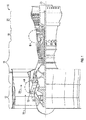
- FIG. 1 is a partial cross-sectional schematic illustration of a gas turbine engine or engine 10. Although a specific gas turbine engine is illustrated in FIG. 1 various embodiments of the present disclosure are contemplated for use in any engine wherein an apparatus and method for removing at least one particles, objects, foreign objects and combinations thereof would be desired.
- Non-limiting examples of such engines include but not limited to the following: turbofan engines, turbojet engines, turboshaft, afterburning turbojet engines, ramjet engines as well as any other equivalent engine wherein the apparatus and methods for removing particles from a fluid stream may be employed according to various embodiments of the present disclosure. Still further, various embodiments of the present disclosure are contemplated for use in any engine that may be suitable for use in an aircraft wherein an apparatus and method for removing particles would be desired.
- the gas turbine engine 10 of FIG. 1 generally has a fan 12 through which ambient air is propelled in the direction of arrow 14 towards an inlet or inlet opening 15 that directs the air towards a compressor 16 for pressurizing the air received from the fan 12 and a combustor 18 wherein the compressed air is mixed with fuel and ignited for generating combustion gases.
- the gas turbine engine 10 further comprises a turbine section 20 for extracting energy from the combustion gases. Fuel is injected into the combustor 18 of the gas turbine engine 10 for mixing with the compressed air from the compressor 16 and ignition of the resultant mixture.
- the fan 12, compressor 16, combustor 18, and turbine 20 are typically all concentric about a common central longitudinal axis of the gas turbine engine 10.
- the gas turbine engine 10 may further comprise a low pressure compressor located in front of a high pressure compressor and a high pressure turbine located in front of a low pressure turbine.
- the compressor 16 may be a multistage compressor 16 that has a low-pressure compressor and a high-pressure compressor and the turbine 20 may be a multistage turbine 20 that has a high-pressure turbine and a low-pressure turbine.
- the low-pressure compressor is connected to the low-pressure turbine and the high pressure compressor is connected to the high-pressure turbine.
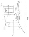
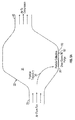
- FIG. 2 illustrates a portion of the gas turbine engine 10 and a particle decelerator 22 for use with the gas turbine engine 10 in accordance with an embodiment of the disclosure.
- particle decelerator 22 may be configured as an annular area disposed about a centre line or axis 23 of the gas turbine engine 10. More particularly and as illustrated in FIG. 2 , the particle decelerator 22 is located downstream of the fan 12 and/or the inlet 15 such that air travelling in the direction of arrow 14 is received in particle decelerator 22. In one embodiment, the particle decelerator 22 may be located in the area "A" depicted in FIG. 1 .
- the air from fan 12 may be divided into a primary air flow path 24 and a secondary air flow path 26, wherein the primary air flow path 24 is directed into particle decelerator 22 via an inlet conduit or passage 28 while the secondary air flow path 26 is received by a passage 30.
- the particle decelerator 22 is configured to capture particles and/or objects or foreign objects located or entrained in the air as it flows into the engine 10 in the direction of arrows 14 and 26.
- particle decelerator 22 is configured to capture particles and/or objects already located in the air prior to it entering the engine.
- particle decelerator refers in a non-limiting fashion to an area configured to slow the velocity particles and/or objects traveling in an air path passing into the particle decelerator such that they are captured in the particle decelerator.
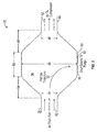
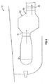
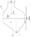
- FIG. 3 is an enlarged view of the particle decelerator 22 of FIG. 2 .
- air from the fan 12 travels into the particle decelerator 22 via conduit or passage 28 and is illustrated by arrows 32.
- the particle decelerator 22 has a receiving area 34 with an area or cross-sectional area that is greater than the area or cross- sectional area of inlet passage or conduit 28.
- the air following into conduit or passage 28 may contain sand and/or other particles and/or objects that are entrained in the air flow depicted by arrows 32.
- the velocity of said particles and/or objects will be reduced or decelerated such that the particles and/or objects will no longer be entrained in the air path and will have a particle trajectory illustrated by arrow 36 due to gravity forces towards an outer shell or wall 38 of the receiving area 34 of the particle decelerator 22.
- the air traveling into the particle decelerator 22 will continue through the receiving area 34 into an exit conduit or passage 40 in fluid communication with receiving area 34.
- this air illustrated by arrows 42 will not have the aforementioned particles and/or objects as they will have dropped off in the direction of arrow 36 due to their reduced velocity and gravity forces.
- the inlet conduit or passage 28 and the outlet conduit or passage 40 will have the same area or cross-sectional area while the area of the receiving area 34 is larger than that of the inlet conduit or passage 28 and the outlet conduit or passage 40. These areas are illustrated in non-limiting fashion by arrows 44, 46 and 48.
- the outer shell or wall 38 of the receiving area 34 of the particle decelerator 22 may be configured to have an opening 50 with a door 52 located therein to allow for purging or removal of the accumulated particles and/or objects that have fallen downwardly in the direction of arrow 36.
- this door 52 may be pivotally secured to the outer shell 38 such that opening 50 may be sealed and unsealed due to the position of door 52 (e.g., either opened or closed).
- the door 52 may be configured to be opened when there is no airflow through particle decelerator 22 in order to allow for ease of particle purging. Alternatively, the door 52 may be opened when air is flowing through the particle decelerator 22 during a purging operation of the engine 10.
- the receiving area 34 of the particle decelerator 22 may have transition areas 54 and 56 located between a central area 58 of the receiving area 34 and the inlet 28 and the outlet 40 passages.
- the particle decelerator 22 is configured such that the inlet conduit or passage 28 is offset from the outlet conduit or passage 40.
- the receiving area 34 and/or transition areas 54 and 56 are configured such that the air flow path from the inlet conduit or passage 28 is offset from the outlet conduit or passage 40, which is illustrated by arrows 60. Still further this offset (illustrated by arrows 60) may also be referred to as the centre line of the inlet conduit or passage 28 is offset from the centre line of the outlet conduit or passage 40.
- a door 52 allows for particles and/or objects to be removed from area 34 via opening 50.
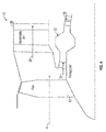
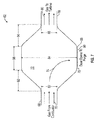
- a particle decelerator 62 is located downstream of the combustor 18 and upstream of the turbine 20.
- the particle decelerator 62 may be located in the area "B" depicted in FIG. 1 .
- the particle decelerator 62 may be configured as an annular area disposed about a centre line or axis 23 of the gas turbine engine 10. Accordingly, an inlet 64 of the particle decelerator 62 is fluidly coupled to the outlet of the combustor 18 and an outlet 66 of the particle decelerator 62 is fluidly coupled to an inlet of the turbine 20.
- the particle decelerator 62 is configured to capture particles and/or objects located or entrained in the air exiting from the combustor 18, which may be particles and/or objects other than those located in the air when it is initially received by the engine 10 for example, objects or particles generated internally by the engine 10 or alternatively the particles and/or objects may comprise both particles and/or objects located or entrained in the air exiting from the combustor 18 and particles and/or objects located in the air when it is initially received by the engine 10.
- particle decelerator refers in a non-limiting fashion to an area configured to slow the velocity particles and/or objects traveling in an air path passing into the particle decelerator such that they are captured in the particle decelerator.
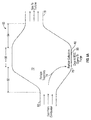
- FIG. 7 is an enlarged view of the particle decelerator 62 of FIG. 6 .
- air or fluid from the combustor 18 travels into the particle decelerator 62 via conduit or passage 68 and is illustrated by arrows 70.
- the particle decelerator 62 has a receiving area 72 with an area or cross-sectional area that is greater than the area or cross-sectional area of inlet passage or conduit 68.
- the air following into conduit or passage 68 may contain particles and/or objects that are entrained in the air flow depicted by arrows 70.
- the velocity of the particles and/or objects will be reduced or decelerated such that the particles and/or objects will no longer be entrained in the air path and will have a particle or object trajectory illustrated by arrow 74 towards an outer shell or wall 76 of the receiving area 72 of the particle decelerator 62.
- the air traveling into the particle decelerator 62 will continue through the receiving area 72 into an exit conduit or passage 78 in fluid communication with receiving area 72.
- this air illustrated by arrows 80 will not have the aforementioned particles and/or objects as they will have dropped off in the direction of arrow 74 due to their reduced velocity and gravity forces.
- the inlet conduit or passage 68 and the outlet conduit or passage 78 will have the same area or cross-sectional area while the area of the receiving area 72 is larger than that of the inlet conduit or passage 68 and the outlet conduit or passage 78. These areas are illustrated in non-limiting fashion by arrows 82, 84 and 86.
- the outer shell or wall 76 of the receiving area 72 of the particle decelerator 62 may be configured to have an opening 88 with a door 90 located therein to allow for purging or removal of the accumulated particles and/or objects that have fallen to the outer shell 76.
- this door 90 may be pivotally secured to the outer shell 76 such that opening 88 may be sealed and unsealed due to the position of door 90 (e.g., either opened or closed).
- the door 90 may be configured to be opened when there is no airflow through particle decelerator 62 in order to allow for ease of particle or object purging. Alternatively, the door 90 may be opened when air is flowing through the particle decelerator 62 during a purging operation of the engine 10.
- the receiving area 72 of the particle decelerator 62 may have transition areas 92 and 94 located between a central area 96 of the receiving area 72 and the inlet 68 and the outlet 78 passages.
- the particle decelerator 62 is configured such that the inlet conduit or passage 68 is offset from the outlet conduit or passage 78.
- the receiving area 72 and/or transition areas 92 and 94 are configured such that the air flow path from the inlet conduit or passage 68 is offset from the outlet conduit or passage 78, which is illustrated by arrows 98.
- this offset (illustrated by arrows 98) may also be referred to as the centre line of the inlet conduit or passage 68 that is offset from the centre line of the outlet conduit or passage 78.
- the gas turbine engine 10 may be configured to have either particle decelerator 22 or 62 each being configured to have an offset flow path or a simply a straight through flow path.
- the gas turbine engine 10 may be configured to have both particle decelerators 22 and 62, wherein one is located before the compressor and one is located before the turbine.
- the decelerators may be configured to have an offset flow path or a simply a straight through flow path.
- the particle decelerators 22 and 62 may be configured to slow the velocity of the particles and/or objects in a range of 1 micron to 10 millimetres that are traveling in an air path passing into the particle decelerator(s) such that they are captured in the particle decelerator(s).
- various embodiments of the disclosure are contemplated for use in capturing particles and/or objects having dimensions outside the aforementioned range and/or located within smaller nested ranges that may be within the aforementioned range or have a portion of the smaller range within the aforementioned range.
Landscapes
- Engineering & Computer Science (AREA)
- Chemical & Material Sciences (AREA)
- Combustion & Propulsion (AREA)
- Mechanical Engineering (AREA)
- General Engineering & Computer Science (AREA)
- Separating Particles In Gases By Inertia (AREA)
Abstract
Description
- This disclosure relates to gas turbine engines, and more particularly to an apparatus and method for removing air particles and/or objects from a gas turbine engine.
- Sand and/or other particles and/or objects entering or travelling thorough a gas turbine can reduce the life of parts in service by erosion and as well as thermos chemical- mechanical degradation (CMAS attack).
- Accordingly, it is desirable to remove the particles and/or objects from the air/gas path of a gas turbine engine.
- In one embodiment, an engine is provided, the engine having: an inlet opening for directing air towards a compressor of the engine; and a particle decelerator located between the inlet opening and the compressor such that air travelling towards the compressor from the inlet opening must travel through the particle decelerator and wherein an area of the particle decelerator is greater than an inlet and an outlet of the particle decelerator.
- In addition to one or more of the features described above, or as an alternative to any of the foregoing embodiments, further embodiments may include an engine wherein the engine is a gas turbine engine and the gas turbine engine may further comprise a fan for directing the air to the compressor and wherein the engine may have a primary air flow path from the fan to the particle decelerator and a secondary air flow path from the fan and away from the particle decelerator.
- In addition to one or more of the features described above, or as an alternative to any of the foregoing embodiments, further embodiments may include a transition area in the area of the particle decelerator and the transition area may be located between the inlet and the outlet of the particle decelerator and wherein the area of the particle decelerator may be an annular area located about an axis of the engine.
- In addition to one or more of the features described above, or as an alternative to any of the foregoing embodiments, further embodiments may include an opening located in an outer shell of the particle decelerator, and a door for sealing the opening in the outer shell of the particle decelerator.
- In addition to one or more of the features described above, or as an alternative to any of the foregoing embodiments, further embodiments may include the particle decelerator being configured such that the inlet is offset from the outlet such that an air flow path from the inlet is offset from the outlet.
- In addition to one or more of the features described above, or as an alternative to any of the foregoing embodiments, further embodiments may include a transition area located between the inlet and the outlet of the particle decelerator.
- In addition to one or more of the features described above, or as an alternative to any of the foregoing embodiments, further embodiments may include an opening located in an outer shell of the particle decelerator, and a door for sealing the opening in the outer shell of the particle decelerator and wherein there is no pressure loss of the air travelling from inlet to the outlet of the particle decelerator.
- In addition to one or more of the features described above, or as an alternative to any of the foregoing embodiments, the engine in accordance with further embodiments may be a gas turbine engine and the gas turbine engine may further comprise a fan for directing the air to the compressor and wherein the engine may further comprise a second particle decelerator located between a combustor and a turbine of the gas turbine engine such that air travelling towards the turbine from the combustor must travel through the second particle decelerator and wherein an area of the second particle decelerator is greater than an inlet and an outlet of the second particle decelerator.
- In addition to one or more of the features described above, or as an alternative to any of the foregoing embodiments, further embodiments may include a primary air flow path from the fan to the particle decelerator and a secondary air flow path from the fan and away from the particle decelerator.
- In addition to one or more of the features described above, or as an alternative to any of the foregoing embodiments, the area of the particle decelerator in accordance with further embodiments may further comprise a transition area located between the inlet and the outlet of the particle decelerator and the second particle decelerator may further comprise a transition area located between the inlet and the outlet of the second particle decelerator and wherein the area of the particle decelerator may be an annular area located about an axis of the engine.
- In addition to one or more of the features described above, or as an alternative to any of the foregoing embodiments, the particle decelerator in accordance with further embodiments may further comprise an opening located in an outer shell of the particle decelerator, and a door for sealing and closing the opening in the outer shell of the particle decelerator and the second particle decelerator may further comprise an opening located in an outer shell of the second particle decelerator, and a door for sealing the opening in the outer shell of the second particle decelerator.
- In addition to one or more of the features described above, or as an alternative to any of the foregoing embodiments, the particle decelerator may be configured such that the inlet of the particle decelerator is offset from the outlet of the particle decelerator such that an air flow path from the inlet of the particle decelerator is offset from the outlet of the particle decelerator and the second particle decelerator may be configured such that the inlet of the second particle decelerator is offset from the outlet of the second particle decelerator such that an air flow path from the inlet of the second particle decelerator is offset from the outlet of the second particle decelerator.
- In addition to one or more of the features described above, or as an alternative to any of the foregoing embodiments, the area of the particle decelerator and the area of the second particle decelerator may further comprise a transition area located between the inlet and the outlet of the particle decelerator and the second particle decelerator.
- In addition to one or more of the features described above, or as an alternative to any of the foregoing embodiments, the particle decelerator may further comprise an opening located in an outer shell of the particle decelerator, and a door for sealing the opening in the outer shell of the particle decelerator and the second particle decelerator may further comprise an opening located in an outer shell of the second particle decelerator, and a door for sealing the opening in the outer shell of the second particle decelerator and wherein there is no pressure loss of the air travelling from inlet to the outlet of the particle decelerator and the second particle decelerator.
- In another embodiment, an engine is provided, the having: a combustor for directing air towards a turbine of the gas turbine engine; and a particle decelerator located between the combustor and the turbine such that air travelling towards the turbine from the combustor must travel through the particle decelerator and wherein an area of the particle decelerator is greater than an inlet and an outlet of the particle decelerator.
- In addition to one or more of the features described above, or as an alternative to any of the foregoing embodiments, the engine may be a gas turbine engine and the area of the particle decelerator further comprises a transition area located between the inlet and the outlet of the particle decelerator.
- In addition to one or more of the features described above, or as an alternative to any of the foregoing embodiments, the particle decelerator may further comprise an opening located in an outer shell of the particle decelerator, and a door for sealing the opening in the outer shell of the particle decelerator.
- In addition to one or more of the features described above, or as an alternative to any of the foregoing embodiments, the particle decelerator may be configured such that the inlet is offset from the outlet such that an air flow path from the inlet is offset from the outlet and wherein the area of the particle decelerator further comprises a transition area located between the inlet and the outlet of the particle decelerator.
- In another embodiment, a method for removing at least one of particles and objects from an air flow path of an engine is provided. The method including the steps of: directing air from an inlet opening of the engine towards a compressor of the engine, wherein a particle decelerator is located in the engine; and decelerating a velocity of at least one of particles and objects located in the air travelling in the particle decelerator such that at least one of the particles and objects are retained in the particle decelerator.
- In addition to one or more of the features described above, or as an alternative to any of the foregoing embodiments, the engine may be a gas turbine engine and the particle decelerator may be located between a fan and the compressor of the gas turbine engine and the gas turbine engine may further comprise a second particle decelerator located between a combustor and a turbine of the gas turbine engine, and the method may further include the steps of: directing air from the combustor of the gas turbine engine towards the turbine of the gas turbine engine; and decelerating a velocity of at least one of particles and objects located in the air travelling in either the particle decelerator or the second particle decelerator such that at least one of the particles and objects are retained in the particle decelerator or the second particle decelerator, and wherein there is no pressure loss in the air traveling through the first particle decelerator and the second particle decelerator.
- In addition to one or more of the features described above, or as an alternative to any of the foregoing embodiments, the engine may be an engine suitable for use in an aircraft.
- The subject matter which is regarded as the present disclosure is particularly pointed out and distinctly claimed in the claims at the conclusion of the specification. The foregoing and other features and advantages of the present disclosure are apparent from the following detailed description taken in conjunction with the accompanying drawings in which:
-
FIG. 1 is a partial cross-sectional schematic illustration of a gas turbine engine; -
FIG. 2 is a partial cross-sectional view of a gas turbine engine illustrating a particle decelerator in accordance with an embodiment of the disclosure; -
FIG. 3 is an enlarged view of the particle decelerator illustrated inFIG. 2 ; -
FIG. 4 is a partial cross-sectional view of a gas turbine engine illustrating a particle decelerator in accordance with an alternative embodiment of the disclosure; -
FIGS. 5A and5B are enlarged views of the particle decelerator illustrated inFIG. 4 ; -
FIG. 6 is a partial cross-sectional view of a gas turbine engine illustrating a particle decelerator in accordance with yet another alternative embodiment of the disclosure; -
FIG. 7 is an enlarged view of the particle decelerator illustrated inFIG. 6 ; -
FIGS. 8A and8B are enlarged views of a particle decelerator illustrated inFIG. 6 in accordance with an alternative embodiment. - Various embodiments of the present disclosure are related to an apparatus and method for removing particles from a gas turbine engine and a gas turbine engine employing the apparatus and method for removing said particles.
-
FIG. 1 is a partial cross-sectional schematic illustration of a gas turbine engine orengine 10. Although a specific gas turbine engine is illustrated inFIG. 1 various embodiments of the present disclosure are contemplated for use in any engine wherein an apparatus and method for removing at least one particles, objects, foreign objects and combinations thereof would be desired. Non-limiting examples of such engines include but not limited to the following: turbofan engines, turbojet engines, turboshaft, afterburning turbojet engines, ramjet engines as well as any other equivalent engine wherein the apparatus and methods for removing particles from a fluid stream may be employed according to various embodiments of the present disclosure. Still further, various embodiments of the present disclosure are contemplated for use in any engine that may be suitable for use in an aircraft wherein an apparatus and method for removing particles would be desired. Thegas turbine engine 10 ofFIG. 1 generally has afan 12 through which ambient air is propelled in the direction ofarrow 14 towards an inlet or inlet opening 15 that directs the air towards acompressor 16 for pressurizing the air received from thefan 12 and acombustor 18 wherein the compressed air is mixed with fuel and ignited for generating combustion gases. - The
gas turbine engine 10 further comprises aturbine section 20 for extracting energy from the combustion gases. Fuel is injected into thecombustor 18 of thegas turbine engine 10 for mixing with the compressed air from thecompressor 16 and ignition of the resultant mixture. Thefan 12,compressor 16,combustor 18, andturbine 20 are typically all concentric about a common central longitudinal axis of thegas turbine engine 10. - The
gas turbine engine 10 may further comprise a low pressure compressor located in front of a high pressure compressor and a high pressure turbine located in front of a low pressure turbine. For example, thecompressor 16 may be amultistage compressor 16 that has a low-pressure compressor and a high-pressure compressor and theturbine 20 may be amultistage turbine 20 that has a high-pressure turbine and a low-pressure turbine. In one embodiment, the low-pressure compressor is connected to the low-pressure turbine and the high pressure compressor is connected to the high-pressure turbine. -
FIG. 2 illustrates a portion of thegas turbine engine 10 and aparticle decelerator 22 for use with thegas turbine engine 10 in accordance with an embodiment of the disclosure. In one embodiment,particle decelerator 22 may be configured as an annular area disposed about a centre line or axis 23 of thegas turbine engine 10. More particularly and as illustrated inFIG. 2 , theparticle decelerator 22 is located downstream of thefan 12 and/or theinlet 15 such that air travelling in the direction ofarrow 14 is received inparticle decelerator 22. In one embodiment, theparticle decelerator 22 may be located in the area "A" depicted inFIG. 1 . As illustrated, the air fromfan 12 may be divided into a primaryair flow path 24 and a secondaryair flow path 26, wherein the primaryair flow path 24 is directed intoparticle decelerator 22 via an inlet conduit orpassage 28 while the secondaryair flow path 26 is received by apassage 30. Theparticle decelerator 22 is configured to capture particles and/or objects or foreign objects located or entrained in the air as it flows into theengine 10 in the direction ofarrows particle decelerator 22 is configured to capture particles and/or objects already located in the air prior to it entering the engine. As used herein, particle decelerator refers in a non-limiting fashion to an area configured to slow the velocity particles and/or objects traveling in an air path passing into the particle decelerator such that they are captured in the particle decelerator. -
FIG. 3 is an enlarged view of theparticle decelerator 22 ofFIG. 2 . As illustrated, air from thefan 12 travels into theparticle decelerator 22 via conduit orpassage 28 and is illustrated byarrows 32. Also shown is that theparticle decelerator 22 has areceiving area 34 with an area or cross-sectional area that is greater than the area or cross- sectional area of inlet passage orconduit 28. As mentioned above, the air following into conduit orpassage 28 may contain sand and/or other particles and/or objects that are entrained in the air flow depicted byarrows 32. However and as this air enters the enlarged area or receivingarea 34 of theparticle decelerator 22, the velocity of said particles and/or objects will be reduced or decelerated such that the particles and/or objects will no longer be entrained in the air path and will have a particle trajectory illustrated byarrow 36 due to gravity forces towards an outer shell orwall 38 of the receivingarea 34 of theparticle decelerator 22. - The air traveling into the
particle decelerator 22 will continue through the receivingarea 34 into an exit conduit orpassage 40 in fluid communication with receivingarea 34. However, this air illustrated byarrows 42 will not have the aforementioned particles and/or objects as they will have dropped off in the direction ofarrow 36 due to their reduced velocity and gravity forces. In one embodiment, the inlet conduit orpassage 28 and the outlet conduit orpassage 40 will have the same area or cross-sectional area while the area of the receivingarea 34 is larger than that of the inlet conduit orpassage 28 and the outlet conduit orpassage 40. These areas are illustrated in non-limiting fashion byarrows - Moreover and in one embodiment, the outer shell or
wall 38 of the receivingarea 34 of theparticle decelerator 22 may be configured to have anopening 50 with adoor 52 located therein to allow for purging or removal of the accumulated particles and/or objects that have fallen downwardly in the direction ofarrow 36. In one embodiment, thisdoor 52 may be pivotally secured to theouter shell 38 such thatopening 50 may be sealed and unsealed due to the position of door 52 (e.g., either opened or closed). Thedoor 52 may be configured to be opened when there is no airflow throughparticle decelerator 22 in order to allow for ease of particle purging. Alternatively, thedoor 52 may be opened when air is flowing through theparticle decelerator 22 during a purging operation of theengine 10. - Still further and in yet another embodiment, the receiving
area 34 of theparticle decelerator 22 may havetransition areas central area 58 of the receivingarea 34 and theinlet 28 and theoutlet 40 passages. - In one embodiment, there is no pressure loss of the fluids or air travelling from
inlet passage 28 into receivingarea 34 and ultimately tooutlet passage 40 asdoor 52 is sealed about opening 50 via a gasket or any other suitable material in order to provide a sealedparticle decelerator 22 - Accordingly and as air travels from inlet conduit or
passage 28 into receivingarea 34 and into outlet conduit orpassage 40, particles are captured in receivingarea 34 ofparticle decelerator 22. As illustrated inFIGS. 2 and3 , the air or fluid received in conduit orpassage 40 has had particles and/or objects removed therefrom due toparticle decelerator 22 and travels on towards thecompressor 16 of thegas turbine engine 10. - Referring now to
FIGS. 4 ,5A and5B , an alternative embodiment of the present disclosure is illustrated. Here, theparticle decelerator 22 is configured such that the inlet conduit orpassage 28 is offset from the outlet conduit orpassage 40. In other words, the receivingarea 34 and/ortransition areas passage 28 is offset from the outlet conduit orpassage 40, which is illustrated byarrows 60. Still further this offset (illustrated by arrows 60) may also be referred to as the centre line of the inlet conduit orpassage 28 is offset from the centre line of the outlet conduit orpassage 40. - Accordingly and not only will particles and/or objects drop off in the direction of
arrow 36 due to the enlarged area of thediffuser 22, they will also be collected at theouter shell 38 as the offset illustrated byarrows 60 will further cause the particles and/or objects to drop downwardly in the direction ofarrow 36. In similar fashion, adoor 52 allows for particles and/or objects to be removed fromarea 34 viaopening 50. - Referring now to
FIG. 6 an alternative embodiment of the disclosure is illustrated. Here aparticle decelerator 62 is located downstream of thecombustor 18 and upstream of theturbine 20. In one embodiment, theparticle decelerator 62 may be located in the area "B" depicted inFIG. 1 . As illustrated, theparticle decelerator 62 may be configured as an annular area disposed about a centre line or axis 23 of thegas turbine engine 10. Accordingly, aninlet 64 of theparticle decelerator 62 is fluidly coupled to the outlet of thecombustor 18 and anoutlet 66 of theparticle decelerator 62 is fluidly coupled to an inlet of theturbine 20. In this embodiment, theparticle decelerator 62 is configured to capture particles and/or objects located or entrained in the air exiting from thecombustor 18, which may be particles and/or objects other than those located in the air when it is initially received by theengine 10 for example, objects or particles generated internally by theengine 10 or alternatively the particles and/or objects may comprise both particles and/or objects located or entrained in the air exiting from thecombustor 18 and particles and/or objects located in the air when it is initially received by theengine 10. As used herein, particle decelerator refers in a non-limiting fashion to an area configured to slow the velocity particles and/or objects traveling in an air path passing into the particle decelerator such that they are captured in the particle decelerator. -
FIG. 7 is an enlarged view of theparticle decelerator 62 ofFIG. 6 . As illustrated, air or fluid from thecombustor 18 travels into theparticle decelerator 62 via conduit orpassage 68 and is illustrated byarrows 70. Also shown is that theparticle decelerator 62 has a receivingarea 72 with an area or cross-sectional area that is greater than the area or cross-sectional area of inlet passage orconduit 68. As mentioned above, the air following into conduit orpassage 68 may contain particles and/or objects that are entrained in the air flow depicted byarrows 70. However and as this air enters the enlarged area or receivingarea 72 of theparticle decelerator 62, the velocity of the particles and/or objects will be reduced or decelerated such that the particles and/or objects will no longer be entrained in the air path and will have a particle or object trajectory illustrated byarrow 74 towards an outer shell orwall 76 of the receivingarea 72 of theparticle decelerator 62. - The air traveling into the
particle decelerator 62 will continue through the receivingarea 72 into an exit conduit orpassage 78 in fluid communication with receivingarea 72. However, this air illustrated byarrows 80 will not have the aforementioned particles and/or objects as they will have dropped off in the direction ofarrow 74 due to their reduced velocity and gravity forces. In one embodiment, the inlet conduit orpassage 68 and the outlet conduit orpassage 78 will have the same area or cross-sectional area while the area of the receivingarea 72 is larger than that of the inlet conduit orpassage 68 and the outlet conduit orpassage 78. These areas are illustrated in non-limiting fashion byarrows - Moreover and in one embodiment, the outer shell or
wall 76 of the receivingarea 72 of theparticle decelerator 62 may be configured to have anopening 88 with adoor 90 located therein to allow for purging or removal of the accumulated particles and/or objects that have fallen to theouter shell 76. In one embodiment, thisdoor 90 may be pivotally secured to theouter shell 76 such thatopening 88 may be sealed and unsealed due to the position of door 90 (e.g., either opened or closed). Thedoor 90 may be configured to be opened when there is no airflow throughparticle decelerator 62 in order to allow for ease of particle or object purging. Alternatively, thedoor 90 may be opened when air is flowing through theparticle decelerator 62 during a purging operation of theengine 10. - Still further and in yet another embodiment, the receiving
area 72 of theparticle decelerator 62 may havetransition areas central area 96 of the receivingarea 72 and theinlet 68 and theoutlet 78 passages. - In one embodiment, there is no pressure loss of the fluids or air travelling from
inlet passage 68 into receivingarea 72 and ultimately tooutlet passage 78 asdoor 90 is sealed about opening 88 via a gasket or any other suitable material in order to provide a sealedparticle decelerator 62. - Accordingly and as air travels from inlet conduit or
passage 68 into receivingarea 72 and into outlet conduit orpassage 78, particles are captured in receivingarea 72 ofparticle decelerator 62. As illustrated inFIGS. 6 and7 , the air or fluid received in conduit orpassage 78 has had particles or objects removed therefrom due toparticle decelerator 62 and travels on towards thecompressor 20 of thegas turbine engine 10. - Referring now to
FIGS. 8A and8B , an alternative embodiment of the present disclosure is illustrated. Here, theparticle decelerator 62 is configured such that the inlet conduit orpassage 68 is offset from the outlet conduit orpassage 78. In other words, the receivingarea 72 and/ortransition areas passage 68 is offset from the outlet conduit orpassage 78, which is illustrated byarrows 98. Still further this offset (illustrated by arrows 98) may also be referred to as the centre line of the inlet conduit orpassage 68 that is offset from the centre line of the outlet conduit orpassage 78. - Accordingly and not only will particles and/or objects drop off in the direction of
arrow 74 due to the enlarged area of thediffuser 62 they will also be collected at theouter shell 76 as the offset illustrated byarrows 98 will further cause the particles and/or objects to drop downwardly in the direction ofarrow 74. - Still further and referring to
FIGS. 1-8A , thegas turbine engine 10 may be configured to have eitherparticle decelerator gas turbine engine 10 may be configured to have bothparticle decelerators - While the present disclosure has been described in detail in connection with only a limited number of embodiments, it should be readily understood that the present disclosure is not limited to such disclosed embodiments. Rather, the present disclosure can be modified to incorporate any number of variations, alterations, substitutions or equivalent arrangements not heretofore described, but which are commensurate with the spirit and scope of the present disclosure. Additionally, while various embodiments of the present disclosure have been described, it is to be understood that aspects of the present disclosure may include only some of the described embodiments. Accordingly, the present disclosure is not to be seen as limited by the foregoing description, but is only limited by the scope of the appended claims.
Claims (14)
- An engine, comprising:an inlet opening for directing air towards a compressor of the engine; anda particle decelerator located between the inlet opening and the compressor such that air travelling towards the compressor from the inlet opening must travel through the particle decelerator and wherein an area of the particle decelerator is greater than an inlet and an outlet of the particle decelerator.
- The engine of claim 1, wherein the engine is a gas turbine engine and the gas turbine engine further comprises a fan for directing the air to the compressor and wherein the engine has a primary air flow path from the fan to the particle decelerator and a secondary air flow path from the fan and away from the particle decelerator and wherein the gas turbine engine is configured for use in an aircraft.
- The engine of claim 1 or claim 2, wherein the engine further comprises a second particle decelerator located between a combustor and a turbine of the gas turbine engine such that air travelling towards the turbine from the combustor must travel through the second particle decelerator and wherein an area of the second particle decelerator is greater than an inlet and an outlet of the second particle decelerator.
- The engine of any preceding claim, wherein the area of the or each particle decelerator further comprises a transition area located between the inlet and the outlet of the or each particle decelerator and wherein the area of the or each particle decelerator is an annular area located about an axis of the engine.
- The engine of any preceding claim, wherein the or each particle decelerator further comprises an opening located in an outer shell of the or each particle decelerator, and a door for sealing the opening in the outer shell of the or each particle decelerator.
- The engine of any preceding claim, wherein the or each particle decelerator is configured such that the inlet is offset from the outlet such that an air flow path from the inlet is offset from the outlet
- The engine of claim 6, wherein the area of the or each particle decelerator further comprises a transition area located between the inlet and the outlet of the or each particle decelerator.
- The engine of claim 6, wherein there is no pressure loss of the air travelling from inlet to the outlet of the or each particle decelerator.
- An engine, comprising:a combustor for directing air towards a turbine of the engine; anda particle decelerator located between the combustor and the turbine such that air travelling towards the turbine from the combustor must travel through the particle decelerator and wherein an area of the particle decelerator is greater than an inlet and an outlet of the particle decelerator.
- The engine of claim 9, wherein the engine is a gas turbine engine and the area of the particle decelerator further comprises a transition area located between the inlet and the outlet of the particle decelerator and wherein the gas turbine engine is configured for use in an aircraft.
- The engine of claim 9 or claim 10, wherein the particle decelerator further comprises an opening located in an outer shell of the particle decelerator, and a door for sealing the opening in the outer shell of the particle decelerator.
- The engine of any of claim 9 to 11, wherein the particle decelerator is configured such that the inlet is offset from the outlet such that an air flow path from the inlet is offset from the outlet and wherein the area of the particle decelerator further comprises a transition area located between the inlet and the outlet of the particle decelerator.
- A method for removing at least one of particles and objects from an air flow path of an engine, comprising:directing air from an inlet opening of the engine towards a compressor of the engine, wherein a particle decelerator is located in the engine; anddecelerating a velocity of at least one of particles and objects located in the air travelling in the particle decelerator such that the at least one of the particles and objects are retained in the particle decelerator.
- The method as in claim 19, wherein the engine is a gas turbine engine configured for use in an aircraft and the particle decelerator is located between a fan and the compressor of the gas turbine engine and wherein the gas turbine engine further comprises a second particle decelerator located between a combustor and a turbine of the gas turbine engine, wherein the method further comprises:directing air from the combustor of the gas turbine engine towards the turbine of the gas turbine engine; anddecelerating a velocity of at least one of particles and objects located in the air travelling in either the particle decelerator or the second particle decelerator such that at least one of the particles and objects are retained in the particle decelerator or the second particle decelerator, and wherein there is no pressure loss in the air traveling through the first particle decelerator and the second particle decelerator.
Applications Claiming Priority (1)
| Application Number | Priority Date | Filing Date | Title |
|---|---|---|---|
| US14/827,892 US10012147B2 (en) | 2015-08-17 | 2015-08-17 | Apparatus and method for air particle separator in gas turbine engine |
Publications (2)
| Publication Number | Publication Date |
|---|---|
| EP3133265A1 true EP3133265A1 (en) | 2017-02-22 |
| EP3133265B1 EP3133265B1 (en) | 2019-12-11 |
Family
ID=56842642
Family Applications (1)
| Application Number | Title | Priority Date | Filing Date |
|---|---|---|---|
| EP16184548.2A Active EP3133265B1 (en) | 2015-08-17 | 2016-08-17 | Apparatus and method for air particle separator in a gas turbine engine |
Country Status (2)
| Country | Link |
|---|---|
| US (1) | US10012147B2 (en) |
| EP (1) | EP3133265B1 (en) |
Families Citing this family (4)
| Publication number | Priority date | Publication date | Assignee | Title |
|---|---|---|---|---|
| US10012147B2 (en) | 2015-08-17 | 2018-07-03 | United Technologies Corporation | Apparatus and method for air particle separator in gas turbine engine |
| FR3069291B1 (en) * | 2017-07-24 | 2019-12-13 | Safran Aircraft Engines | SUPPLY DUCT FOR A COMPRESSOR OF A TURBOMACHINE |
| US10612466B2 (en) * | 2017-09-11 | 2020-04-07 | United Technologies Corporation | Gas turbine engine active clearance control system using inlet particle separator |
| US11512683B2 (en) * | 2019-10-08 | 2022-11-29 | Typhon Technology Solutions (U.S.), Llc | Chilled intake air for increased power generation |
Citations (5)
| Publication number | Priority date | Publication date | Assignee | Title |
|---|---|---|---|---|
| US5039317A (en) * | 1990-07-05 | 1991-08-13 | Allied-Signal Inc. | Radial inflow particle separation method and apparatus |
| US20070144139A1 (en) * | 2004-12-06 | 2007-06-28 | Honda Motor Co., Ltd. | Gas turbine engine provided with a foreign matter removal passage |
| US20120000168A1 (en) * | 2010-06-30 | 2012-01-05 | General Electric Company | Inlet air filtration system |
| US20120233973A1 (en) * | 2011-03-17 | 2012-09-20 | Sedillo Patrick M | Variable flow particle separating structure |
| US20150040535A1 (en) * | 2013-08-07 | 2015-02-12 | Honeywell International Inc. | Inlet particle separator system with hub and/or shroud suction |
Family Cites Families (14)
| Publication number | Priority date | Publication date | Assignee | Title |
|---|---|---|---|---|
| US3720045A (en) * | 1970-11-16 | 1973-03-13 | Avco Corp | Dynamic blade particle separator |
| US3673771A (en) * | 1970-11-23 | 1972-07-04 | Avco Corp | Multi-channel particle separator |
| US4466239A (en) * | 1983-02-22 | 1984-08-21 | General Electric Company | Gas turbine engine with improved air cooling circuit |
| US5123240A (en) * | 1990-03-19 | 1992-06-23 | General Electric Co. | Method and apparatus for ejecting foreign matter from the primary flow path of a gas turbine engine |
| DE4335136C2 (en) * | 1992-10-22 | 1999-12-16 | Alstom Energy Syst Gmbh | Method and device for carrying out the method for generating gases for operating a gas turbine in a combined gas and steam power plant |
| US5725180A (en) * | 1995-12-29 | 1998-03-10 | General Electric Company | Aircraft engine pitot plenum intake |
| US6250068B1 (en) * | 1998-07-22 | 2001-06-26 | Hitachi, Ltd. | Gas turbine installation |
| US6647708B2 (en) * | 2002-03-05 | 2003-11-18 | Williams International Co., L.L.C. | Multi-spool by-pass turbofan engine |
| US7770375B2 (en) | 2006-02-09 | 2010-08-10 | United Technologies Corporation | Particle collector for gas turbine engine |
| US8092145B2 (en) | 2008-10-28 | 2012-01-10 | Pratt & Whitney Canada Corp. | Particle separator and separating method for gas turbine engine |
| US8561411B2 (en) | 2009-09-02 | 2013-10-22 | United Technologies Corporation | Air particle separator for a gas turbine engine |
| US20120070271A1 (en) * | 2010-09-21 | 2012-03-22 | Urban Justin R | Gas turbine engine with bleed duct for minimum reduction of bleed flow and minimum rejection of hail during hail ingestion events |
| CN203114426U (en) * | 2011-07-09 | 2013-08-07 | 拉姆金动力系统有限责任公司 | Gas turbine engine and device for gas turbine engine |
| US10012147B2 (en) | 2015-08-17 | 2018-07-03 | United Technologies Corporation | Apparatus and method for air particle separator in gas turbine engine |
-
2015
- 2015-08-17 US US14/827,892 patent/US10012147B2/en active Active
-
2016
- 2016-08-17 EP EP16184548.2A patent/EP3133265B1/en active Active
Patent Citations (5)
| Publication number | Priority date | Publication date | Assignee | Title |
|---|---|---|---|---|
| US5039317A (en) * | 1990-07-05 | 1991-08-13 | Allied-Signal Inc. | Radial inflow particle separation method and apparatus |
| US20070144139A1 (en) * | 2004-12-06 | 2007-06-28 | Honda Motor Co., Ltd. | Gas turbine engine provided with a foreign matter removal passage |
| US20120000168A1 (en) * | 2010-06-30 | 2012-01-05 | General Electric Company | Inlet air filtration system |
| US20120233973A1 (en) * | 2011-03-17 | 2012-09-20 | Sedillo Patrick M | Variable flow particle separating structure |
| US20150040535A1 (en) * | 2013-08-07 | 2015-02-12 | Honeywell International Inc. | Inlet particle separator system with hub and/or shroud suction |
Also Published As
| Publication number | Publication date |
|---|---|
| US10012147B2 (en) | 2018-07-03 |
| EP3133265B1 (en) | 2019-12-11 |
| US20170051669A1 (en) | 2017-02-23 |
Similar Documents
| Publication | Publication Date | Title |
|---|---|---|
| US11073083B2 (en) | Particle separator | |
| EP3196442B1 (en) | Inlet particle separator for a turbine engine | |
| CN106801630B (en) | Shroud assembly for a gas turbine engine | |
| US10167725B2 (en) | Engine component for a turbine engine | |
| US9046056B2 (en) | Inlet particle separator system for a gas turbine engine | |
| US8037683B2 (en) | Flow-optimized bypass for turbo engines | |
| EP3260687A1 (en) | Inlet particle separator system with pre-cleaner flow passage | |
| US10245540B2 (en) | Inertial particle separator for engine inlet | |
| US20180135516A1 (en) | Scavenge methodologies for turbine engine particle separation concepts | |
| US10400670B2 (en) | Inlet particle separator for a turbine engine | |
| US11199111B2 (en) | Assembly for particle removal | |
| EP3133265B1 (en) | Apparatus and method for air particle separator in a gas turbine engine | |
| CN106988793B (en) | Nozzle assembly for gas-turbine unit | |
| EP3147481B1 (en) | Apparatus and method for air particle separation in a gas turbine engine | |
| US10835848B2 (en) | Apparatus and method for air particle capture in a gas turbine engine |
Legal Events
| Date | Code | Title | Description |
|---|---|---|---|
| PUAI | Public reference made under article 153(3) epc to a published international application that has entered the european phase |
Free format text: ORIGINAL CODE: 0009012 |
|
| STAA | Information on the status of an ep patent application or granted ep patent |
Free format text: STATUS: THE APPLICATION HAS BEEN PUBLISHED |
|
| AK | Designated contracting states |
Kind code of ref document: A1 Designated state(s): AL AT BE BG CH CY CZ DE DK EE ES FI FR GB GR HR HU IE IS IT LI LT LU LV MC MK MT NL NO PL PT RO RS SE SI SK SM TR |
|
| AX | Request for extension of the european patent |
Extension state: BA ME |
|
| STAA | Information on the status of an ep patent application or granted ep patent |
Free format text: STATUS: REQUEST FOR EXAMINATION WAS MADE |
|
| 17P | Request for examination filed |
Effective date: 20170816 |
|
| RBV | Designated contracting states (corrected) |
Designated state(s): AL AT BE BG CH CY CZ DE DK EE ES FI FR GB GR HR HU IE IS IT LI LT LU LV MC MK MT NL NO PL PT RO RS SE SI SK SM TR |
|
| REG | Reference to a national code |
Ref country code: DE Ref legal event code: R079 Ref document number: 602016025894 Country of ref document: DE Free format text: PREVIOUS MAIN CLASS: F02C0007052000 Ipc: F01D0009020000 |
|
| STAA | Information on the status of an ep patent application or granted ep patent |
Free format text: STATUS: EXAMINATION IS IN PROGRESS |
|
| RIC1 | Information provided on ipc code assigned before grant |
Ipc: F02C 7/052 20060101ALI20180406BHEP Ipc: F01D 25/32 20060101ALI20180406BHEP Ipc: F01D 9/02 20060101AFI20180406BHEP |
|
| 17Q | First examination report despatched |
Effective date: 20180419 |
|
| GRAJ | Information related to disapproval of communication of intention to grant by the applicant or resumption of examination proceedings by the epo deleted |
Free format text: ORIGINAL CODE: EPIDOSDIGR1 |
|
| GRAP | Despatch of communication of intention to grant a patent |
Free format text: ORIGINAL CODE: EPIDOSNIGR1 |
|
| GRAP | Despatch of communication of intention to grant a patent |
Free format text: ORIGINAL CODE: EPIDOSNIGR1 |
|
| STAA | Information on the status of an ep patent application or granted ep patent |
Free format text: STATUS: GRANT OF PATENT IS INTENDED |
|
| INTG | Intention to grant announced |
Effective date: 20190129 |
|
| GRAJ | Information related to disapproval of communication of intention to grant by the applicant or resumption of examination proceedings by the epo deleted |
Free format text: ORIGINAL CODE: EPIDOSDIGR1 |
|
| STAA | Information on the status of an ep patent application or granted ep patent |
Free format text: STATUS: EXAMINATION IS IN PROGRESS |
|
| GRAP | Despatch of communication of intention to grant a patent |
Free format text: ORIGINAL CODE: EPIDOSNIGR1 |
|
| STAA | Information on the status of an ep patent application or granted ep patent |
Free format text: STATUS: GRANT OF PATENT IS INTENDED |
|
| INTC | Intention to grant announced (deleted) | ||
| INTG | Intention to grant announced |
Effective date: 20190626 |
|
| GRAS | Grant fee paid |
Free format text: ORIGINAL CODE: EPIDOSNIGR3 |
|
| GRAA | (expected) grant |
Free format text: ORIGINAL CODE: 0009210 |
|
| STAA | Information on the status of an ep patent application or granted ep patent |
Free format text: STATUS: THE PATENT HAS BEEN GRANTED |
|
| AK | Designated contracting states |
Kind code of ref document: B1 Designated state(s): AL AT BE BG CH CY CZ DE DK EE ES FI FR GB GR HR HU IE IS IT LI LT LU LV MC MK MT NL NO PL PT RO RS SE SI SK SM TR |
|
| REG | Reference to a national code |
Ref country code: GB Ref legal event code: FG4D |
|
| REG | Reference to a national code |
Ref country code: CH Ref legal event code: EP |
|
| REG | Reference to a national code |
Ref country code: AT Ref legal event code: REF Ref document number: 1212384 Country of ref document: AT Kind code of ref document: T Effective date: 20191215 |
|
| REG | Reference to a national code |
Ref country code: DE Ref legal event code: R096 Ref document number: 602016025894 Country of ref document: DE |
|
| REG | Reference to a national code |
Ref country code: IE Ref legal event code: FG4D |
|
| REG | Reference to a national code |
Ref country code: NL Ref legal event code: MP Effective date: 20191211 |
|
| REG | Reference to a national code |
Ref country code: LT Ref legal event code: MG4D |
|
| PG25 | Lapsed in a contracting state [announced via postgrant information from national office to epo] |
Ref country code: FI Free format text: LAPSE BECAUSE OF FAILURE TO SUBMIT A TRANSLATION OF THE DESCRIPTION OR TO PAY THE FEE WITHIN THE PRESCRIBED TIME-LIMIT Effective date: 20191211 Ref country code: LV Free format text: LAPSE BECAUSE OF FAILURE TO SUBMIT A TRANSLATION OF THE DESCRIPTION OR TO PAY THE FEE WITHIN THE PRESCRIBED TIME-LIMIT Effective date: 20191211 Ref country code: GR Free format text: LAPSE BECAUSE OF FAILURE TO SUBMIT A TRANSLATION OF THE DESCRIPTION OR TO PAY THE FEE WITHIN THE PRESCRIBED TIME-LIMIT Effective date: 20200312 Ref country code: NO Free format text: LAPSE BECAUSE OF FAILURE TO SUBMIT A TRANSLATION OF THE DESCRIPTION OR TO PAY THE FEE WITHIN THE PRESCRIBED TIME-LIMIT Effective date: 20200311 Ref country code: SE Free format text: LAPSE BECAUSE OF FAILURE TO SUBMIT A TRANSLATION OF THE DESCRIPTION OR TO PAY THE FEE WITHIN THE PRESCRIBED TIME-LIMIT Effective date: 20191211 Ref country code: LT Free format text: LAPSE BECAUSE OF FAILURE TO SUBMIT A TRANSLATION OF THE DESCRIPTION OR TO PAY THE FEE WITHIN THE PRESCRIBED TIME-LIMIT Effective date: 20191211 Ref country code: BG Free format text: LAPSE BECAUSE OF FAILURE TO SUBMIT A TRANSLATION OF THE DESCRIPTION OR TO PAY THE FEE WITHIN THE PRESCRIBED TIME-LIMIT Effective date: 20200311 |
|
| PG25 | Lapsed in a contracting state [announced via postgrant information from national office to epo] |
Ref country code: HR Free format text: LAPSE BECAUSE OF FAILURE TO SUBMIT A TRANSLATION OF THE DESCRIPTION OR TO PAY THE FEE WITHIN THE PRESCRIBED TIME-LIMIT Effective date: 20191211 Ref country code: RS Free format text: LAPSE BECAUSE OF FAILURE TO SUBMIT A TRANSLATION OF THE DESCRIPTION OR TO PAY THE FEE WITHIN THE PRESCRIBED TIME-LIMIT Effective date: 20191211 |
|
| PG25 | Lapsed in a contracting state [announced via postgrant information from national office to epo] |
Ref country code: AL Free format text: LAPSE BECAUSE OF FAILURE TO SUBMIT A TRANSLATION OF THE DESCRIPTION OR TO PAY THE FEE WITHIN THE PRESCRIBED TIME-LIMIT Effective date: 20191211 |
|
| PG25 | Lapsed in a contracting state [announced via postgrant information from national office to epo] |
Ref country code: EE Free format text: LAPSE BECAUSE OF FAILURE TO SUBMIT A TRANSLATION OF THE DESCRIPTION OR TO PAY THE FEE WITHIN THE PRESCRIBED TIME-LIMIT Effective date: 20191211 Ref country code: PT Free format text: LAPSE BECAUSE OF FAILURE TO SUBMIT A TRANSLATION OF THE DESCRIPTION OR TO PAY THE FEE WITHIN THE PRESCRIBED TIME-LIMIT Effective date: 20200506 Ref country code: NL Free format text: LAPSE BECAUSE OF FAILURE TO SUBMIT A TRANSLATION OF THE DESCRIPTION OR TO PAY THE FEE WITHIN THE PRESCRIBED TIME-LIMIT Effective date: 20191211 Ref country code: CZ Free format text: LAPSE BECAUSE OF FAILURE TO SUBMIT A TRANSLATION OF THE DESCRIPTION OR TO PAY THE FEE WITHIN THE PRESCRIBED TIME-LIMIT Effective date: 20191211 Ref country code: RO Free format text: LAPSE BECAUSE OF FAILURE TO SUBMIT A TRANSLATION OF THE DESCRIPTION OR TO PAY THE FEE WITHIN THE PRESCRIBED TIME-LIMIT Effective date: 20191211 Ref country code: ES Free format text: LAPSE BECAUSE OF FAILURE TO SUBMIT A TRANSLATION OF THE DESCRIPTION OR TO PAY THE FEE WITHIN THE PRESCRIBED TIME-LIMIT Effective date: 20191211 |
|
| PG25 | Lapsed in a contracting state [announced via postgrant information from national office to epo] |
Ref country code: SM Free format text: LAPSE BECAUSE OF FAILURE TO SUBMIT A TRANSLATION OF THE DESCRIPTION OR TO PAY THE FEE WITHIN THE PRESCRIBED TIME-LIMIT Effective date: 20191211 Ref country code: IS Free format text: LAPSE BECAUSE OF FAILURE TO SUBMIT A TRANSLATION OF THE DESCRIPTION OR TO PAY THE FEE WITHIN THE PRESCRIBED TIME-LIMIT Effective date: 20200411 Ref country code: SK Free format text: LAPSE BECAUSE OF FAILURE TO SUBMIT A TRANSLATION OF THE DESCRIPTION OR TO PAY THE FEE WITHIN THE PRESCRIBED TIME-LIMIT Effective date: 20191211 |
|
| REG | Reference to a national code |
Ref country code: DE Ref legal event code: R097 Ref document number: 602016025894 Country of ref document: DE |
|
| REG | Reference to a national code |
Ref country code: AT Ref legal event code: MK05 Ref document number: 1212384 Country of ref document: AT Kind code of ref document: T Effective date: 20191211 |
|
| PLBE | No opposition filed within time limit |
Free format text: ORIGINAL CODE: 0009261 |
|
| STAA | Information on the status of an ep patent application or granted ep patent |
Free format text: STATUS: NO OPPOSITION FILED WITHIN TIME LIMIT |
|
| PG25 | Lapsed in a contracting state [announced via postgrant information from national office to epo] |
Ref country code: DK Free format text: LAPSE BECAUSE OF FAILURE TO SUBMIT A TRANSLATION OF THE DESCRIPTION OR TO PAY THE FEE WITHIN THE PRESCRIBED TIME-LIMIT Effective date: 20191211 |
|
| 26N | No opposition filed |
Effective date: 20200914 |
|
| PG25 | Lapsed in a contracting state [announced via postgrant information from national office to epo] |
Ref country code: AT Free format text: LAPSE BECAUSE OF FAILURE TO SUBMIT A TRANSLATION OF THE DESCRIPTION OR TO PAY THE FEE WITHIN THE PRESCRIBED TIME-LIMIT Effective date: 20191211 Ref country code: SI Free format text: LAPSE BECAUSE OF FAILURE TO SUBMIT A TRANSLATION OF THE DESCRIPTION OR TO PAY THE FEE WITHIN THE PRESCRIBED TIME-LIMIT Effective date: 20191211 |
|
| PG25 | Lapsed in a contracting state [announced via postgrant information from national office to epo] |
Ref country code: IT Free format text: LAPSE BECAUSE OF FAILURE TO SUBMIT A TRANSLATION OF THE DESCRIPTION OR TO PAY THE FEE WITHIN THE PRESCRIBED TIME-LIMIT Effective date: 20191211 |
|
| PG25 | Lapsed in a contracting state [announced via postgrant information from national office to epo] |
Ref country code: PL Free format text: LAPSE BECAUSE OF FAILURE TO SUBMIT A TRANSLATION OF THE DESCRIPTION OR TO PAY THE FEE WITHIN THE PRESCRIBED TIME-LIMIT Effective date: 20191211 |
|
| PG25 | Lapsed in a contracting state [announced via postgrant information from national office to epo] |
Ref country code: MC Free format text: LAPSE BECAUSE OF FAILURE TO SUBMIT A TRANSLATION OF THE DESCRIPTION OR TO PAY THE FEE WITHIN THE PRESCRIBED TIME-LIMIT Effective date: 20191211 |
|
| REG | Reference to a national code |
Ref country code: CH Ref legal event code: PL |
|
| PG25 | Lapsed in a contracting state [announced via postgrant information from national office to epo] |
Ref country code: LU Free format text: LAPSE BECAUSE OF NON-PAYMENT OF DUE FEES Effective date: 20200817 Ref country code: LI Free format text: LAPSE BECAUSE OF NON-PAYMENT OF DUE FEES Effective date: 20200831 Ref country code: CH Free format text: LAPSE BECAUSE OF NON-PAYMENT OF DUE FEES Effective date: 20200831 |
|
| REG | Reference to a national code |
Ref country code: BE Ref legal event code: MM Effective date: 20200831 |
|
| PG25 | Lapsed in a contracting state [announced via postgrant information from national office to epo] |
Ref country code: IE Free format text: LAPSE BECAUSE OF NON-PAYMENT OF DUE FEES Effective date: 20200817 Ref country code: BE Free format text: LAPSE BECAUSE OF NON-PAYMENT OF DUE FEES Effective date: 20200831 |
|
| PG25 | Lapsed in a contracting state [announced via postgrant information from national office to epo] |
Ref country code: TR Free format text: LAPSE BECAUSE OF FAILURE TO SUBMIT A TRANSLATION OF THE DESCRIPTION OR TO PAY THE FEE WITHIN THE PRESCRIBED TIME-LIMIT Effective date: 20191211 Ref country code: MT Free format text: LAPSE BECAUSE OF FAILURE TO SUBMIT A TRANSLATION OF THE DESCRIPTION OR TO PAY THE FEE WITHIN THE PRESCRIBED TIME-LIMIT Effective date: 20191211 Ref country code: CY Free format text: LAPSE BECAUSE OF FAILURE TO SUBMIT A TRANSLATION OF THE DESCRIPTION OR TO PAY THE FEE WITHIN THE PRESCRIBED TIME-LIMIT Effective date: 20191211 |
|
| PG25 | Lapsed in a contracting state [announced via postgrant information from national office to epo] |
Ref country code: MK Free format text: LAPSE BECAUSE OF FAILURE TO SUBMIT A TRANSLATION OF THE DESCRIPTION OR TO PAY THE FEE WITHIN THE PRESCRIBED TIME-LIMIT Effective date: 20191211 |
|
| REG | Reference to a national code |
Ref country code: DE Ref legal event code: R081 Ref document number: 602016025894 Country of ref document: DE Owner name: RAYTHEON TECHNOLOGIES CORPORATION (N.D.GES.D.S, US Free format text: FORMER OWNER: UNITED TECHNOLOGIES CORPORATION, FARMINGTON, CONN., US Ref country code: DE Ref legal event code: R081 Ref document number: 602016025894 Country of ref document: DE Owner name: RTX CORPORATION (N.D.GES.D. STAATES DELAWARE),, US Free format text: FORMER OWNER: UNITED TECHNOLOGIES CORPORATION, FARMINGTON, CONN., US |
|
| P01 | Opt-out of the competence of the unified patent court (upc) registered |
Effective date: 20230520 |
|
| PGFP | Annual fee paid to national office [announced via postgrant information from national office to epo] |
Ref country code: DE Payment date: 20250724 Year of fee payment: 10 |
|
| PGFP | Annual fee paid to national office [announced via postgrant information from national office to epo] |
Ref country code: GB Payment date: 20250725 Year of fee payment: 10 |
|
| PGFP | Annual fee paid to national office [announced via postgrant information from national office to epo] |
Ref country code: FR Payment date: 20250725 Year of fee payment: 10 |
|
| REG | Reference to a national code |
Ref country code: DE Ref legal event code: R081 Ref document number: 602016025894 Country of ref document: DE Owner name: RTX CORPORATION (N.D.GES.D. STAATES DELAWARE),, US Free format text: FORMER OWNER: RAYTHEON TECHNOLOGIES CORPORATION (N.D.GES.D.STAATES DELAWARE), ARLINGTON, VA, US |