EP3132955A1 - Rollo assembly and open roof construction for a vehicle provided therewith - Google Patents
Rollo assembly and open roof construction for a vehicle provided therewith Download PDFInfo
- Publication number
- EP3132955A1 EP3132955A1 EP15178560.7A EP15178560A EP3132955A1 EP 3132955 A1 EP3132955 A1 EP 3132955A1 EP 15178560 A EP15178560 A EP 15178560A EP 3132955 A1 EP3132955 A1 EP 3132955A1
- Authority
- EP
- European Patent Office
- Prior art keywords
- rollo
- light
- assembly according
- end portion
- screen
- Prior art date
- Legal status (The legal status is an assumption and is not a legal conclusion. Google has not performed a legal analysis and makes no representation as to the accuracy of the status listed.)
- Granted
Links
Images




Classifications
-
- B—PERFORMING OPERATIONS; TRANSPORTING
- B60—VEHICLES IN GENERAL
- B60J—WINDOWS, WINDSCREENS, NON-FIXED ROOFS, DOORS, OR SIMILAR DEVICES FOR VEHICLES; REMOVABLE EXTERNAL PROTECTIVE COVERINGS SPECIALLY ADAPTED FOR VEHICLES
- B60J7/00—Non-fixed roofs; Roofs with movable panels, e.g. rotary sunroofs
- B60J7/0007—Non-fixed roofs; Roofs with movable panels, e.g. rotary sunroofs moveable head-liners, screens, curtains or blinds for ceilings
- B60J7/0015—Non-fixed roofs; Roofs with movable panels, e.g. rotary sunroofs moveable head-liners, screens, curtains or blinds for ceilings roller blind
-
- B—PERFORMING OPERATIONS; TRANSPORTING
- B60—VEHICLES IN GENERAL
- B60J—WINDOWS, WINDSCREENS, NON-FIXED ROOFS, DOORS, OR SIMILAR DEVICES FOR VEHICLES; REMOVABLE EXTERNAL PROTECTIVE COVERINGS SPECIALLY ADAPTED FOR VEHICLES
- B60J7/00—Non-fixed roofs; Roofs with movable panels, e.g. rotary sunroofs
- B60J7/0007—Non-fixed roofs; Roofs with movable panels, e.g. rotary sunroofs moveable head-liners, screens, curtains or blinds for ceilings
- B60J7/0023—Non-fixed roofs; Roofs with movable panels, e.g. rotary sunroofs moveable head-liners, screens, curtains or blinds for ceilings flexible and foldable
-
- B—PERFORMING OPERATIONS; TRANSPORTING
- B60—VEHICLES IN GENERAL
- B60J—WINDOWS, WINDSCREENS, NON-FIXED ROOFS, DOORS, OR SIMILAR DEVICES FOR VEHICLES; REMOVABLE EXTERNAL PROTECTIVE COVERINGS SPECIALLY ADAPTED FOR VEHICLES
- B60J7/00—Non-fixed roofs; Roofs with movable panels, e.g. rotary sunroofs
- B60J7/02—Non-fixed roofs; Roofs with movable panels, e.g. rotary sunroofs of sliding type, e.g. comprising guide shoes
- B60J7/04—Non-fixed roofs; Roofs with movable panels, e.g. rotary sunroofs of sliding type, e.g. comprising guide shoes with rigid plate-like element or elements, e.g. open roofs with harmonica-type folding rigid panels
- B60J7/043—Sunroofs e.g. sliding above the roof
-
- B—PERFORMING OPERATIONS; TRANSPORTING
- B60—VEHICLES IN GENERAL
- B60Q—ARRANGEMENT OF SIGNALLING OR LIGHTING DEVICES, THE MOUNTING OR SUPPORTING THEREOF OR CIRCUITS THEREFOR, FOR VEHICLES IN GENERAL
- B60Q3/00—Arrangement of lighting devices for vehicle interiors; Lighting devices specially adapted for vehicle interiors
- B60Q3/20—Arrangement of lighting devices for vehicle interiors; Lighting devices specially adapted for vehicle interiors for lighting specific fittings of passenger or driving compartments; mounted on specific fittings of passenger or driving compartments
- B60Q3/208—Sun roofs; Windows
-
- B—PERFORMING OPERATIONS; TRANSPORTING
- B60—VEHICLES IN GENERAL
- B60Q—ARRANGEMENT OF SIGNALLING OR LIGHTING DEVICES, THE MOUNTING OR SUPPORTING THEREOF OR CIRCUITS THEREFOR, FOR VEHICLES IN GENERAL
- B60Q3/00—Arrangement of lighting devices for vehicle interiors; Lighting devices specially adapted for vehicle interiors
- B60Q3/60—Arrangement of lighting devices for vehicle interiors; Lighting devices specially adapted for vehicle interiors characterised by optical aspects
- B60Q3/62—Arrangement of lighting devices for vehicle interiors; Lighting devices specially adapted for vehicle interiors characterised by optical aspects using light guides
- B60Q3/64—Arrangement of lighting devices for vehicle interiors; Lighting devices specially adapted for vehicle interiors characterised by optical aspects using light guides for a single lighting device
-
- B—PERFORMING OPERATIONS; TRANSPORTING
- B60—VEHICLES IN GENERAL
- B60Q—ARRANGEMENT OF SIGNALLING OR LIGHTING DEVICES, THE MOUNTING OR SUPPORTING THEREOF OR CIRCUITS THEREFOR, FOR VEHICLES IN GENERAL
- B60Q3/00—Arrangement of lighting devices for vehicle interiors; Lighting devices specially adapted for vehicle interiors
- B60Q3/70—Arrangement of lighting devices for vehicle interiors; Lighting devices specially adapted for vehicle interiors characterised by the purpose
- B60Q3/78—Arrangement of lighting devices for vehicle interiors; Lighting devices specially adapted for vehicle interiors characterised by the purpose for generating luminous strips, e.g. for marking trim component edges
Definitions
- the invention in a first aspect relates to a rollo assembly intended for use in an open roof construction for a vehicle, comprising a rollo screen having opposite forward and rearward sides and two opposite lateral sides, a winding tube for winding and unwinding the rollo screen at the rearward side, an operating beam connected to the forward side and having two outer ends, and two longitudinally extending guides for guiding respective ones of the outer ends of the operating beam and respective ones of the lateral sides of the rollo screen, wherein said lateral sides are provided with retention members cooperating with corresponding parts of the guides for retaining said lateral sides in said guides.
- the rollo assembly is characterized in that the rollo screen is provided with light transmitting and emitting members which have an end portion extending at least up to a first one of the lateral sides of the rollo screen and wherein at least the guide intended for guiding said first one of the lateral sides is provided with at least one elongate light bar extending longitudinally along said guide in such a position that it can transmit light into said end portion of the light transmitting and emitting members.
- a stationary elongate light bar allows to transmit light into the end portions of the light transmitting and emitting members and this light then is evenly distributed and emitted over the entire rollo screen (that is to say, everywhere over the rollo screen where the light transmitting and emitting members are provided). This effect is maintained, irrespective whether the rollo screen is moving or has assumed a stationary position. There is no need for complicated optical or electrical connections (the latter in the case that a light source would be integrated into the rollo screen) nor for expensive switch-arrangements.
- the rollo assembly Because there is no physical contact between the light bar and the light transmitting and emitting members, the rollo assembly experiences little wear and thus has a very long life span and frictional forces during moving the rollo screen are minimised (thus less force is required for moving the rollo screen).
- such a light bar without any problem can be combined with the retention members which assure that the lateral sides of the rollo screen cannot come out of the guides. As a result a reliable rollo assembly for a vehicle is achieved with attractive lighting properties.
- the entire amount of rollo screen wound off (that is to say, everywhere over the rollo screen where the light transmitting and emitting members are provided) is lightened. This applies too in a partly deployed position. In such a partly deployed position, however, the lighting bar also emits light at places where the rollo screen is not present, causing an attractive type of ambient lighting.
- said end portion of the light transmitting and emitting members substantially ends at the respective lateral side of the rollo screen. This means that the respective members have an outer end substantially coinciding with said lateral side.
- the elongate light bar is located laterally with respect to the respective lateral side of the rollo screen (thus that light emitted by the light bar will enter a frontal end of the light transmitting and emitting members). This allows to keep the dimensions of the rollo assembly, especially perpendicularly to the rollo screen (the so-called packaging height), as small as possible.
- said end portion of the light transmitting and emitting members protrudes laterally beyond the respective lateral side of the rollo screen. This means that the respective members do not end at the lateral side, but extend a little but further out of (beyond) the rollo screen's lateral side.
- the elongate light bar is located above or below said protruding end portion.
- the light emitted by the light bar enters the light transmitting and emitting members from a side of the latter and not at a frontal end of latter.
- Such an embodiment also offers the opportunity to provide said protruding end portion at its outer end with a retention member (for example comprising strips attached to an upper and lower surface of the protruding end and received in corresponding parts of the guide).
- a retention member for example comprising strips attached to an upper and lower surface of the protruding end and received in corresponding parts of the guide.
- the elongate light bar is located laterally with respect to the respective protruding end portion.
- the elongate light bar is provided with a recess extending longitudinally and intended for at least partially receiving said protruding end portion. This may increase the efficiency of transmission of light from the light bar into said light transmitting and emitting members.
- said recess may be provided with chamfered walls.
- the elongate light bar comprises two opposite frontal ends, wherein a light source is positioned at at least one of said frontal ends.
- the light source may be of any appropriate type to effectively transmit light into the light bar (for example a LED). It is conceivable that at both frontal ends of the light bar such a light source is provided.
- both guides are provided with a light bar for cooperation with respective end portions of light transmitting and emitting members in the vicinity of both lateral sides of the rollo screen.
- Said members also may have two end portions at opposite lateral sides and thus cooperating with two light bars, but it too is possible that each light transmitting and emitting member only has one end portion cooperating with a single light bar and that end portions of a first group of members cooperate with one light bar only and end portions of another group of members cooperate with the other light bar only. Combinations of such embodiments are conceivable too.
- the retention members comprise hook-like retention members cooperating with respective parts of the guides and provided at at least one of the upper and lower surfaces of the rollo screen. There may be provided more than one of such hook-like retention members at a lateral side (for example one on the upper surface and one on the lower surface of the rollo screen).
- the hook-like retention members (which may extend continuously or intermittently in a longitudinal direction) may be separate parts attached to the rollo screen, but also may comprise inwardly folded edge parts of the rollo screen. Such hook-like retention members improve the retention of the lateral side of the rollo screen in the guide (and prevent that the lateral side is pulled out of the guide).
- the light bars comprise injection moulded parts (integrated into the guides and for example made of glass fibre) with a cross sectional area between 4 and 40 mm 2 , and preferably between 4 and 10 mm 2 , per each meter of length of a said light bar.
- the light bars have an outer surface which at least partially, preferably opposite said end portion, is provided with means for improving the transmission of light into said end portion, such as a light reflecting layer, a roughening or, preferably triangular, protruding parts, such that the efficiency of the light bars in terms of light transmission only into the end portions of the light transmitting and emitting members is further improved.
- the light bars have a cross section which in a direction towards the end portion tapers to a reduced thickness, preferably substantially to the thickness of the end portion.
- a taper may have different shapes and further improves the efficiency of the light transmission towards the end portion.
- the light transmitting and emitting members are positioned at the side of the rollo screen facing an interior of the vehicle.
- a position on top of the rollo screen (or both) is possible too, as well as a position sandwiched between two rollo screen layers (of which, then, the lower at least partially should be transparent for the light emitted).
- the light transmitting and emitting members comprise glass fibres oriented transversally and preferably woven into the rollo screen.
- the thickness of said glass fibres may lie in a range from 0,1 to 1 mm (enabling the rollo screen to be wound onto the winding tube), and preferably in a range from 0,25 to 0,5 mm.
- the light transmitting and emitting members are combined into a single flexible foil), which preferably is adhered to the side of the rollo screen facing an interior of the vehicle. This means that there are no separate members, but a single foil (capable of transmitting and emitting light) extending over the respective part of (in most cases all of) the rollo screen, of which foil at least one lateral edge portion cooperates with a light bar.
- the foil is sandwiched between two layers of the rollo screen.
- the invention in a second aspect relates to an open roof construction for a vehicle, comprising a roof opening in a stationary roof part, a movable panel which can move relative to said roof opening and a rollo assembly according to the present invention of which the rollo screen is movable between a position for freeing said roof opening and a position for closing said roof opening.
- FIG 2 one half of an open roof construction is illustrated which, as shown in figure 1 , generally comprises a roof opening 1 in a stationary roof part 2, a movable panel 3 which can move relative to said roof opening 1 (by means known per se and not shown here) and a rollo assembly to be elucidated below (of which in figure 1 only an operating beam 9 is visible).
- the rollo assembly comprises a rollo screen 4 (made for example of a cloth material) which is movable between a position for freeing said roof opening 1 and a position for closing (or obscuring) said roof opening.
- the rollo screen 4 has a forward side 5, an opposite rearward side 6 and two opposite lateral sides 7 (of which obviously only one has been shown).
- a winding tube 8 is provided for winding and unwinding the rollo screen 4 at the rearward side 6.
- An operating beam 9 is connected to the forward side 5 and has two outer ends 10 (of which obviously only one has been shown). Further two longitudinally extending guides 11 (of which obviously only one has been shown) are illustrated for guiding respective ones of the outer ends 10 of the operating beam 9 and respective ones of the lateral sides 7 of the rollo screen 4.
- the lateral sides 7 of the rollo screen 4 are provided with retention members cooperating with corresponding parts of the guides 11 for retaining said lateral sides 7 in said guides 11.
- the rollo screen 4 is provided with light transmitting and emitting members 12 which have an end portion 13 extending at least up to a first one of the lateral sides 7 of the rollo screen 4.
- These members 12 may be provided in the rollo screen 4 in any desired pattern and it is conceivable that the entire rollo screen 4 or only some parts thereof are provided with such members 12.
- At least the guide 11 intended for guiding said first one of the lateral sides 7 of the rollo screen 4 is provided with at least one elongate light bar 14 extending longitudinally along said guide 11 in such a position that it can transmit light into said end portion 13 of the light transmitting and emitting members 12.
- the elongate light bar 14 comprises two opposite frontal ends 15 and a light source 16 (for example an LED) is positioned at each of said ends 15.
- the light emitted by the light sources 16 enters the light bar 14 at said frontal ends 15 and is emitted by the light bar 14 over its entire length and will enter the end portions 13 of the members 12 which will transmit (distribute) and emit the light over the rollo screen 4 in accordance with their pattern over the rollo screen.
- the light bars 14 preferably are provided with means for improving the transmission of light into said end portions 13 only, as will appear later.
- both guides 11 are provided with a light bar 14 for cooperation with respective end portions 13 of light transmitting and emitting members 12 in the vicinity of both lateral sides 7 of the rollo screen 4.
- the light bars 14 may comprise injection moulded parts with a cross sectional area between 4 and 40 mm 2 , and preferably between 4 and 10 mm 2 , per each meter of length of a said light bar.
- the cross section of the light bars 14 may have any desired shape, such as circular, square, rectangular, oval or even other, more irregular, shapes, as will appear later.
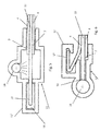
- figures 3-13 which, schematically and in part, illustrate cross sections (as viewed in a longitudinal direction according to A-A in figure 2 ) of different embodiments in a region of a guide 11.
- Figure 3 shows an embodiment of a rollo assembly in which the end portion 13 of the light transmitting and emitting members 12 substantially ends at the respective lateral side 7 of the rollo screen 4.
- the elongate light bar 14 is located laterally with respect to the respective lateral side 7 of the rollo screen 4 and is housed in a correspondingly shaped part of the guide 11.
- Figure 3 further shows a hook-like retention member 17 cooperating with a respective part 11' of the guide 11.
- the retention member 17 is provided on the upper surface of the rollo screen 4, but in other embodiments it may be located on the lower surface (e.g. figure 7 ) or on both (e.g. figure 8 ).
- the retention member 17 may be a separate part attached to the rollo screen 4 in any appropriate manner, or may be an integral part thereof (for example a folded back part).
- the retention member 17 does not interfere with the operation of the light bar 14.
- the retention member 17 also may protrude transversally beyond the end 13 of the members 12.
- the figures 5-10 all illustrate embodiments in which said end portion 13 of the light transmitting and emitting members 12 protrudes laterally beyond the respective lateral side 7 of the rollo screen 4.
- the elongate light bar 14 is located above said protruding end 13 (although a position below it is conceivable too). Further this embodiment comprises a retention member 18 provided at an outer end of the protruding end 13 and cooperating with a corresponding part 11'of the guide.
- Figure 6 illustrates an embodiment in which the elongate light bar 14 is located laterally with respect to the respective protruding end portion 13.
- the figures 7-10 relate to embodiments in which the elongate light bar 14 is provided with a recess 19 extending longitudinally and intended for at least partially receiving said protruding end portion 13.
- a single retention member 17 is provided on a lower surface of the rollo screen 4
- two retention members 17 are provided, both on the upper and lower surface of the rollo screen 4.
- FIGS 9 and 10 special embodiments of the light bar 14 are shown.
- the light bar 14 has a square cross section and at least a part of the outer surface of the light bar is covered with a light reflecting layer 20 (for example a white layer) for improving the efficiency of the light bar (assuring that light only is emitted towards the end portion 13).
- a light reflecting layer 20 for example a white layer
- layer 20 may be replaced by a roughening or protruding (preferably triangular) parts.
- such a reflecting layer 20 is provided on the entire outer surface of the light bar 14 (which in this embodiment has a circular cross section). Further, in this embodiment, the recess 19 is provided with chamfered walls 21 for even more increasing the efficiency of the light bar 14.
- the light transmitting and emitting members 12 are illustrated as sandwiched between two layers of the rollo screen 4. However, also other embodiments are conceivable, for example wherein the members 12 are provided on top or below the rollo screen 4. As another alternative the light transmitting and emitting members 12 may comprise glass fibres oriented transversally and preferably woven into the rollo screen 4.
- the light transmitting and emitting members 12 may be combined into a single flexible foil (having light transmitting and emitting characteristics) which in figure 1 in broken lines has been indicated as foil 12'.
- a foil 12' may be adhered to one side of the rollo screen 4, preferably the lower side (facing an interior of the vehicle), but also may be sandwiched between two rollo screen layers.
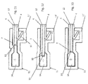
- FIG-13 illustrate embodiments in which the light bar 14 tapers towards the end portion 13.
- the light bar 14 as a result has a bottle shaped cross section.
- the light bar tapers and has a recess 19 in its tapering part which therefore partly surrounds the end portion 13.
- the tapering part frontally faces the end portion 13.
- a guide is provided with more than one light bar, which light bars may be positioned at different positions relative to the end portion of the light transmitting and emitting members.
Landscapes
- Engineering & Computer Science (AREA)
- Mechanical Engineering (AREA)
- Operating, Guiding And Securing Of Roll- Type Closing Members (AREA)
- Light Guides In General And Applications Therefor (AREA)
Abstract
Description
- In a first aspect the invention relates to a rollo assembly intended for use in an open roof construction for a vehicle, comprising a rollo screen having opposite forward and rearward sides and two opposite lateral sides, a winding tube for winding and unwinding the rollo screen at the rearward side, an operating beam connected to the forward side and having two outer ends, and two longitudinally extending guides for guiding respective ones of the outer ends of the operating beam and respective ones of the lateral sides of the rollo screen, wherein said lateral sides are provided with retention members cooperating with corresponding parts of the guides for retaining said lateral sides in said guides.
- It is an object of the present invention to provide an improved rollo assembly of such a type.
- Thus, in accordance with the present invention the rollo assembly is characterized in that the rollo screen is provided with light transmitting and emitting members which have an end portion extending at least up to a first one of the lateral sides of the rollo screen and wherein at least the guide intended for guiding said first one of the lateral sides is provided with at least one elongate light bar extending longitudinally along said guide in such a position that it can transmit light into said end portion of the light transmitting and emitting members.
- The use of a stationary elongate light bar allows to transmit light into the end portions of the light transmitting and emitting members and this light then is evenly distributed and emitted over the entire rollo screen (that is to say, everywhere over the rollo screen where the light transmitting and emitting members are provided). This effect is maintained, irrespective whether the rollo screen is moving or has assumed a stationary position. There is no need for complicated optical or electrical connections (the latter in the case that a light source would be integrated into the rollo screen) nor for expensive switch-arrangements. Because there is no physical contact between the light bar and the light transmitting and emitting members, the rollo assembly experiences little wear and thus has a very long life span and frictional forces during moving the rollo screen are minimised (thus less force is required for moving the rollo screen). In accordance with the present invention such a light bar without any problem can be combined with the retention members which assure that the lateral sides of the rollo screen cannot come out of the guides. As a result a reliable rollo assembly for a vehicle is achieved with attractive lighting properties.
- When the rollo screen is in a fully deployed position (a position in which it is unwound from the winding tube to a maximum extent), the entire amount of rollo screen wound off (that is to say, everywhere over the rollo screen where the light transmitting and emitting members are provided) is lightened. This applies too in a partly deployed position. In such a partly deployed position, however, the lighting bar also emits light at places where the rollo screen is not present, causing an attractive type of ambient lighting.
- In an embodiment of the rollo assembly said end portion of the light transmitting and emitting members substantially ends at the respective lateral side of the rollo screen. This means that the respective members have an outer end substantially coinciding with said lateral side.
- Then it is conceivable that the elongate light bar is located laterally with respect to the respective lateral side of the rollo screen (thus that light emitted by the light bar will enter a frontal end of the light transmitting and emitting members). This allows to keep the dimensions of the rollo assembly, especially perpendicularly to the rollo screen (the so-called packaging height), as small as possible.
- In another type of embodiment said end portion of the light transmitting and emitting members protrudes laterally beyond the respective lateral side of the rollo screen. This means that the respective members do not end at the lateral side, but extend a little but further out of (beyond) the rollo screen's lateral side.
- In such an embodiment it is possible that the elongate light bar is located above or below said protruding end portion. In such an embodiment the light emitted by the light bar enters the light transmitting and emitting members from a side of the latter and not at a frontal end of latter.
- Such an embodiment also offers the opportunity to provide said protruding end portion at its outer end with a retention member (for example comprising strips attached to an upper and lower surface of the protruding end and received in corresponding parts of the guide).
- However, as an alternative the elongate light bar is located laterally with respect to the respective protruding end portion.
- In a specific embodiment the elongate light bar is provided with a recess extending longitudinally and intended for at least partially receiving said protruding end portion. This may increase the efficiency of transmission of light from the light bar into said light transmitting and emitting members.
- For further improving such efficiency said recess may be provided with chamfered walls.
- In yet another embodiment the elongate light bar comprises two opposite frontal ends, wherein a light source is positioned at at least one of said frontal ends. The light source may be of any appropriate type to effectively transmit light into the light bar (for example a LED). It is conceivable that at both frontal ends of the light bar such a light source is provided.
- In one embodiment of the rollo assembly according to the present invention both guides are provided with a light bar for cooperation with respective end portions of light transmitting and emitting members in the vicinity of both lateral sides of the rollo screen. This means that at both sides of the rollo screen light bars are provided for transmitting light into such members. Said members also may have two end portions at opposite lateral sides and thus cooperating with two light bars, but it too is possible that each light transmitting and emitting member only has one end portion cooperating with a single light bar and that end portions of a first group of members cooperate with one light bar only and end portions of another group of members cooperate with the other light bar only. Combinations of such embodiments are conceivable too.
- In another embodiment the retention members comprise hook-like retention members cooperating with respective parts of the guides and provided at at least one of the upper and lower surfaces of the rollo screen. There may be provided more than one of such hook-like retention members at a lateral side (for example one on the upper surface and one on the lower surface of the rollo screen). The hook-like retention members (which may extend continuously or intermittently in a longitudinal direction) may be separate parts attached to the rollo screen, but also may comprise inwardly folded edge parts of the rollo screen. Such hook-like retention members improve the retention of the lateral side of the rollo screen in the guide (and prevent that the lateral side is pulled out of the guide).
- In one embodiment the light bars comprise injection moulded parts (integrated into the guides and for example made of glass fibre) with a cross sectional area between 4 and 40 mm2, and preferably between 4 and 10 mm2, per each meter of length of a said light bar.
- In another embodiment the light bars have an outer surface which at least partially, preferably opposite said end portion, is provided with means for improving the transmission of light into said end portion, such as a light reflecting layer, a roughening or, preferably triangular, protruding parts, such that the efficiency of the light bars in terms of light transmission only into the end portions of the light transmitting and emitting members is further improved.
- In one embodiment the light bars have a cross section which in a direction towards the end portion tapers to a reduced thickness, preferably substantially to the thickness of the end portion. Such a taper may have different shapes and further improves the efficiency of the light transmission towards the end portion.
- In one embodiment the light transmitting and emitting members are positioned at the side of the rollo screen facing an interior of the vehicle. However, a position on top of the rollo screen (or both) is possible too, as well as a position sandwiched between two rollo screen layers (of which, then, the lower at least partially should be transparent for the light emitted).
- In another embodiment the light transmitting and emitting members comprise glass fibres oriented transversally and preferably woven into the rollo screen. However, other orientations of such glass fibres may be used too, if necessary. The thickness of said glass fibres may lie in a range from 0,1 to 1 mm (enabling the rollo screen to be wound onto the winding tube), and preferably in a range from 0,25 to 0,5 mm.
- In a special embodiment of the rollo assembly the light transmitting and emitting members are combined into a single flexible foil), which preferably is adhered to the side of the rollo screen facing an interior of the vehicle. This means that there are no separate members, but a single foil (capable of transmitting and emitting light) extending over the respective part of (in most cases all of) the rollo screen, of which foil at least one lateral edge portion cooperates with a light bar.
- It also is possible that the foil is sandwiched between two layers of the rollo screen.
- In a second aspect the invention relates to an open roof construction for a vehicle, comprising a roof opening in a stationary roof part, a movable panel which can move relative to said roof opening and a rollo assembly according to the present invention of which the rollo screen is movable between a position for freeing said roof opening and a position for closing said roof opening.
- Hereinafter the invention will be elucidated while referring to the drawings, in which:
-
Figure 1 schematically illustrates part of a vehicle with an open roof construction provided with a rollo assembly; -
Figure 2 schematically and in a perspective view illustrates one half of an open roof construction provided with a rollo assembly according to the present invention, and -
Figures 3-13 show different embodiments of the rollo assembly in a partial cross section according to A-A infigure 2 . - Firstly referring to
figure 2 one half of an open roof construction is illustrated which, as shown infigure 1 , generally comprises a roof opening 1 in astationary roof part 2, amovable panel 3 which can move relative to said roof opening 1 (by means known per se and not shown here) and a rollo assembly to be elucidated below (of which infigure 1 only anoperating beam 9 is visible). - The rollo assembly comprises a rollo screen 4 (made for example of a cloth material) which is movable between a position for freeing said roof opening 1 and a position for closing (or obscuring) said roof opening. The
rollo screen 4 has aforward side 5, an oppositerearward side 6 and two opposite lateral sides 7 (of which obviously only one has been shown). Awinding tube 8 is provided for winding and unwinding therollo screen 4 at therearward side 6. Anoperating beam 9 is connected to theforward side 5 and has two outer ends 10 (of which obviously only one has been shown). Further two longitudinally extending guides 11 (of which obviously only one has been shown) are illustrated for guiding respective ones of theouter ends 10 of theoperating beam 9 and respective ones of thelateral sides 7 of therollo screen 4. - As will appear later (for example in relation to
figures 3,4 and6-8 ) thelateral sides 7 of therollo screen 4 are provided with retention members cooperating with corresponding parts of theguides 11 for retaining saidlateral sides 7 insaid guides 11. - The
rollo screen 4 is provided with light transmitting and emittingmembers 12 which have anend portion 13 extending at least up to a first one of thelateral sides 7 of therollo screen 4. Thesemembers 12 may be provided in therollo screen 4 in any desired pattern and it is conceivable that theentire rollo screen 4 or only some parts thereof are provided withsuch members 12. - At least the
guide 11 intended for guiding said first one of thelateral sides 7 of therollo screen 4 is provided with at least oneelongate light bar 14 extending longitudinally along saidguide 11 in such a position that it can transmit light into saidend portion 13 of the light transmitting and emittingmembers 12. - In the illustrated embodiment the
elongate light bar 14 comprises two oppositefrontal ends 15 and a light source 16 (for example an LED) is positioned at each of saidends 15. The light emitted by thelight sources 16 enters thelight bar 14 at saidfrontal ends 15 and is emitted by thelight bar 14 over its entire length and will enter theend portions 13 of themembers 12 which will transmit (distribute) and emit the light over therollo screen 4 in accordance with their pattern over the rollo screen. - The light bars 14 preferably are provided with means for improving the transmission of light into said
end portions 13 only, as will appear later. - Preferably both guides 11 (thus also the one not illustrated) are provided with a
light bar 14 for cooperation withrespective end portions 13 of light transmitting and emittingmembers 12 in the vicinity of bothlateral sides 7 of therollo screen 4. - The light bars 14 may comprise injection moulded parts with a cross sectional area between 4 and 40 mm2, and preferably between 4 and 10 mm2, per each meter of length of a said light bar.
- The cross section of the light bars 14 may have any desired shape, such as circular, square, rectangular, oval or even other, more irregular, shapes, as will appear later.
- Next reference is made to
figures 3-13 which, schematically and in part, illustrate cross sections (as viewed in a longitudinal direction according to A-A infigure 2 ) of different embodiments in a region of aguide 11. -
Figure 3 shows an embodiment of a rollo assembly in which theend portion 13 of the light transmitting and emittingmembers 12 substantially ends at the respectivelateral side 7 of therollo screen 4. The elongatelight bar 14 is located laterally with respect to the respectivelateral side 7 of therollo screen 4 and is housed in a correspondingly shaped part of theguide 11. -
Figure 3 further shows a hook-like retention member 17 cooperating with a respective part 11' of theguide 11. In this embodiment theretention member 17 is provided on the upper surface of therollo screen 4, but in other embodiments it may be located on the lower surface (e.g.figure 7 ) or on both (e.g.figure 8 ). Theretention member 17 may be a separate part attached to therollo screen 4 in any appropriate manner, or may be an integral part thereof (for example a folded back part). - Due to the specific design in accordance with the present invention, the
retention member 17 does not interfere with the operation of thelight bar 14. - As illustrated in the embodiment of
figure 4 , theretention member 17 also may protrude transversally beyond theend 13 of themembers 12. - The
figures 5-10 all illustrate embodiments in which saidend portion 13 of the light transmitting and emittingmembers 12 protrudes laterally beyond the respectivelateral side 7 of therollo screen 4. - In
figure 5 the elongatelight bar 14 is located above said protruding end 13 (although a position below it is conceivable too). Further this embodiment comprises aretention member 18 provided at an outer end of theprotruding end 13 and cooperating with a corresponding part 11'of the guide. -
Figure 6 illustrates an embodiment in which the elongatelight bar 14 is located laterally with respect to the respectiveprotruding end portion 13. - The
figures 7-10 relate to embodiments in which the elongatelight bar 14 is provided with arecess 19 extending longitudinally and intended for at least partially receiving saidprotruding end portion 13. Infigure 7 asingle retention member 17 is provided on a lower surface of therollo screen 4, whereas infigure 8 tworetention members 17 are provided, both on the upper and lower surface of therollo screen 4. - In
figures 9 and 10 special embodiments of thelight bar 14 are shown. Infigure 9 thelight bar 14 has a square cross section and at least a part of the outer surface of the light bar is covered with a light reflecting layer 20 (for example a white layer) for improving the efficiency of the light bar (assuring that light only is emitted towards the end portion 13). - As an alternative,
layer 20 may be replaced by a roughening or protruding (preferably triangular) parts. - In the embodiment according to
figure 10 such a reflectinglayer 20 is provided on the entire outer surface of the light bar 14 (which in this embodiment has a circular cross section). Further, in this embodiment, therecess 19 is provided with chamferedwalls 21 for even more increasing the efficiency of thelight bar 14. - In most of the embodiments illustrated the light transmitting and emitting
members 12 are illustrated as sandwiched between two layers of therollo screen 4. However, also other embodiments are conceivable, for example wherein themembers 12 are provided on top or below therollo screen 4. As another alternative the light transmitting and emittingmembers 12 may comprise glass fibres oriented transversally and preferably woven into therollo screen 4. - In another embodiment the light transmitting and emitting
members 12 may be combined into a single flexible foil (having light transmitting and emitting characteristics) which infigure 1 in broken lines has been indicated as foil 12'. Such a foil 12' may be adhered to one side of therollo screen 4, preferably the lower side (facing an interior of the vehicle), but also may be sandwiched between two rollo screen layers. - Finally
figures 11-13 illustrate embodiments in which thelight bar 14 tapers towards theend portion 13. Infigure 11 thelight bar 14 as a result has a bottle shaped cross section. Infigure 12 the light bar tapers and has arecess 19 in its tapering part which therefore partly surrounds theend portion 13. Infigure 13 the tapering part frontally faces theend portion 13. - The invention is not limited to the embodiments described before which may be varied widely within the scope of the invention as defined by the appending claims. For example it is possible that a guide is provided with more than one light bar, which light bars may be positioned at different positions relative to the end portion of the light transmitting and emitting members.
Claims (19)
- Rollo assembly intended for use in an open roof construction for a vehicle, comprising a rollo screen (4) having opposite forward (5) and rearward (6) sides and two opposite lateral sides (7), a winding tube (8) for winding and unwinding the rollo screen at the rearward side, an operating beam (9) connected to the forward side and having two outer ends (10), and two longitudinally extending guides (11) for guiding respective ones of the outer ends (10) of the operating beam (9) and respective ones of the lateral sides (7) of the rollo screen (4), wherein said lateral sides are provided with retention members (17;18) cooperating with corresponding parts (11') of the guides (11) for retaining said lateral sides in said guides, characterized in that the rollo screen (4) is provided with light transmitting and emitting members (12) which have an end portion (13) extending at least up to a first one of the lateral sides (7) of the rollo screen and wherein at least the guide (11) intended for guiding said first one of the lateral sides is provided with at least one elongate light bar (14) extending longitudinally along said guide in such a position that it can transmit light into said end portion of the light transmitting and emitting members (12).
- Rollo assembly according to claim 1, wherein said end portion (13) of the light transmitting and emitting members (12) substantially ends at the respective lateral side (7) of the rollo screen (4).
- Rollo assembly according to claim 2, wherein the elongate light bar (14) is located laterally with respect to the respective lateral side (7) of the rollo screen (4).
- Rollo assembly according to claim 1, wherein said end portion (13) of the light transmitting and emitting members (12) protrudes laterally beyond the respective lateral side (7) of the rollo screen (4).
- Rollo assembly according to claim 4, wherein the elongate light bar (14) is located above or below said protruding end portion (13).
- Rollo assembly according to claim 4 or 5, wherein said protruding end portion (13) at its outer end is provided with a retention member (18).
- Rollo assembly according to claim 4, wherein the elongate light bar (14) is located laterally with respect to the respective protruding end portion (13).
- Rollo assembly according to claim 7, wherein the elongate light bar (14) is provided with a recess (19) extending longitudinally and intended for at least partially receiving said protruding end portion (13).
- Rollo assembly according to claim 8, wherein said recess (19) is provided with chamfered walls (21).
- Rollo assembly according to any of the previous claims, wherein the elongate light bar (14) comprises two opposite frontal ends (15) and wherein a light source (16) is positioned at at least one of said frontal ends.
- Rollo assembly according to any of the previous claims, wherein both guides (11) are provided with a light bar (14) for cooperation with respective end portions (13) of light transmitting and emitting members (12) in the vicinity of both lateral sides (7) of the rollo screen (4).
- Rollo assembly according to any of the previous claims, wherein the retention members (17) comprise hook-like retention members cooperating with respective parts (11') of the guides (11) and provided at at least one of the upper and lower surfaces of the rollo screen (4).
- Rollo assembly according to any of the previous claims, wherein the light bars (14) comprise injection moulded parts with a cross sectional area between 4 and 40 mm2, and preferably between 4 and 10 mm2, per each meter of length of a said light bar.
- Rollo assembly according to any of the previous claims, wherein the light bars (14) have an outer surface which at least partially, preferably opposite said end portion (13), is provided with means for improving the transmission of light into said end portion (13), such as a light reflecting layer (20), a roughening or, preferably triangular, protruding parts.
- Rollo assembly according to any of the previous claims and claim 7, wherein the light bars (14) have a cross section which in a direction towards the end portion (13) tapers to a reduced thickness, preferably substantially to the thickness of the end portion.
- Rollo assembly according to any of the previous claims, wherein the light transmitting and emitting members (12) are positioned at the side of the rollo screen (4) facing an interior of the vehicle.
- Rollo assembly according to any of the previous claims, wherein the light transmitting and emitting members (12) comprise glass fibres oriented transversally and preferably woven into the rollo screen (4).
- Rollo assembly according to any of the claims 1-16, wherein the light transmitting and emitting members (12) are combined into a single flexible foil (12'), which preferably is adhered to the side of the rollo screen (4) facing an interior of the vehicle.
- Open roof construction for a vehicle, comprising a roof opening (1) in a stationary roof part (2), a movable panel (3) which can move relative to said roof opening and a rollo assembly according to any of the previous claims of which the rollo screen (4) is movable between a position for freeing said roof opening (1) and a position for closing said roof opening.
Priority Applications (3)
| Application Number | Priority Date | Filing Date | Title |
|---|---|---|---|
| EP15178560.7A EP3132955B1 (en) | 2015-07-28 | 2015-07-28 | Rollo assembly and open roof construction for a vehicle provided therewith |
| CN201610389500.8A CN106394202B (en) | 2015-07-28 | 2016-06-03 | Roller blind assembly and open roof construction for a vehicle provided with a roller blind assembly |
| US15/184,623 US9815354B2 (en) | 2015-07-28 | 2016-06-16 | Rollo assembly and open roof construction for a vehicle provided therewith |
Applications Claiming Priority (1)
| Application Number | Priority Date | Filing Date | Title |
|---|---|---|---|
| EP15178560.7A EP3132955B1 (en) | 2015-07-28 | 2015-07-28 | Rollo assembly and open roof construction for a vehicle provided therewith |
Publications (2)
| Publication Number | Publication Date |
|---|---|
| EP3132955A1 true EP3132955A1 (en) | 2017-02-22 |
| EP3132955B1 EP3132955B1 (en) | 2020-04-08 |
Family
ID=53762021
Family Applications (1)
| Application Number | Title | Priority Date | Filing Date |
|---|---|---|---|
| EP15178560.7A Active EP3132955B1 (en) | 2015-07-28 | 2015-07-28 | Rollo assembly and open roof construction for a vehicle provided therewith |
Country Status (3)
| Country | Link |
|---|---|
| US (1) | US9815354B2 (en) |
| EP (1) | EP3132955B1 (en) |
| CN (1) | CN106394202B (en) |
Cited By (2)
| Publication number | Priority date | Publication date | Assignee | Title |
|---|---|---|---|---|
| DE102019129752A1 (en) | 2018-11-06 | 2020-05-07 | Webasto SE | Vehicle blind device with a lighting device |
| DE102020102354A1 (en) | 2020-01-31 | 2021-08-05 | Bayerische Motoren Werke Aktiengesellschaft | Lighting system for illuminating a headliner of a vehicle, a vehicle with such a lighting system and a method for illuminating a headliner |
Families Citing this family (7)
| Publication number | Priority date | Publication date | Assignee | Title |
|---|---|---|---|---|
| CN205697099U (en) * | 2016-04-20 | 2016-11-23 | 皇田工业股份有限公司 | Luminous cloth curtain device |
| WO2018206600A1 (en) * | 2017-05-11 | 2018-11-15 | Bos Gmbh & Co. Kg | Protection device for a motor vehicle interior |
| CN109435652A (en) * | 2018-12-24 | 2019-03-08 | 上海毓恬冠佳汽车零部件有限公司 | A kind of sun-blind device for vehicle roof |
| DE102019112013B4 (en) * | 2019-05-08 | 2021-09-23 | Gebrüder Jaeger GmbH | Attachment tape for attaching a shading material to a guide and method |
| CN110920359B (en) * | 2019-11-18 | 2021-06-01 | 宁波帅特龙集团有限公司 | A sunshade wrapping structure |
| DE102021203478A1 (en) * | 2021-04-08 | 2022-10-13 | Bos Gmbh & Co. Kg | Protective device for a motor vehicle interior |
| CN113547902B (en) * | 2021-06-30 | 2023-06-27 | 宁波尚宏汽车天窗有限公司 | Luminous sun-shading curtain assembly |
Citations (6)
| Publication number | Priority date | Publication date | Assignee | Title |
|---|---|---|---|---|
| DE19936537A1 (en) * | 1999-08-03 | 2001-02-15 | Daimler Chrysler Ag | Screening device to cover transparent regions of motor vehicle has means of electric lighting provided on or in screening element, and light fitting may be constructed as cross support of screening element |
| WO2006105768A1 (en) * | 2005-04-05 | 2006-10-12 | Webasto Ag | Shade assembly for a transparent bodywork surface of a vehicle |
| DE102009033885A1 (en) * | 2009-07-20 | 2011-01-27 | Macauto Industrial Co., Ltd., Yung-Kang | Vehicle roof-roller blind arrangement, has guide device with guide insert projecting into lower sliding groove and bent part between insertion parts to press bent part transverse to fabric blind and in lower sliding groove |
| FR2991931A1 (en) * | 2012-06-18 | 2013-12-20 | Webasto Systemes Carrosserie | OCCULTATION DEVICE HAVING A LIGHT SOURCE |
| DE102013104341A1 (en) * | 2013-04-29 | 2014-10-30 | Webasto SE | Roller blind arrangement for a vehicle |
| DE102013011605A1 (en) * | 2013-07-11 | 2015-01-15 | Webasto SE | Roller blind arrangement with integrated lighting |
Family Cites Families (8)
| Publication number | Priority date | Publication date | Assignee | Title |
|---|---|---|---|---|
| DE29908994U1 (en) * | 1999-05-21 | 1999-07-29 | Reitter & Schefenacker GmbH & Co. KG, 73730 Esslingen | Interior lighting of vehicles, preferably motor vehicles |
| US6631943B2 (en) * | 2001-01-26 | 2003-10-14 | Mueller Hermann-Frank | Sliding roof for motor vehicles |
| US6863424B2 (en) * | 2002-08-07 | 2005-03-08 | Whelen Engineering Company, Inc. | Light bar with integrated warning illumination and lens support structure |
| DE102004046386A1 (en) * | 2004-09-24 | 2006-04-06 | Schefenacker Vision Systems Germany Gmbh & Co. Kg | Light guide for lights, in particular for lights of motor vehicles |
| KR20100020318A (en) * | 2008-08-12 | 2010-02-22 | 현대자동차주식회사 | Sunroof for a vehicle |
| FR2948068B1 (en) * | 2009-07-15 | 2012-10-26 | Peugeot Citroen Automobiles Sa | DEVICE FOR OCCULATING A VEHICLE PAVILION WITH A GUIDE (S) WITH INTEGRATED LIGHT (S) |
| US8419119B2 (en) * | 2010-10-26 | 2013-04-16 | Yachiyo Industry Co., Ltd. | Sunshade device |
| US20170010404A1 (en) * | 2015-07-09 | 2017-01-12 | Pixon Technologies Corp. | Linear light source with flexible printed circuit |
-
2015
- 2015-07-28 EP EP15178560.7A patent/EP3132955B1/en active Active
-
2016
- 2016-06-03 CN CN201610389500.8A patent/CN106394202B/en active Active
- 2016-06-16 US US15/184,623 patent/US9815354B2/en active Active
Patent Citations (6)
| Publication number | Priority date | Publication date | Assignee | Title |
|---|---|---|---|---|
| DE19936537A1 (en) * | 1999-08-03 | 2001-02-15 | Daimler Chrysler Ag | Screening device to cover transparent regions of motor vehicle has means of electric lighting provided on or in screening element, and light fitting may be constructed as cross support of screening element |
| WO2006105768A1 (en) * | 2005-04-05 | 2006-10-12 | Webasto Ag | Shade assembly for a transparent bodywork surface of a vehicle |
| DE102009033885A1 (en) * | 2009-07-20 | 2011-01-27 | Macauto Industrial Co., Ltd., Yung-Kang | Vehicle roof-roller blind arrangement, has guide device with guide insert projecting into lower sliding groove and bent part between insertion parts to press bent part transverse to fabric blind and in lower sliding groove |
| FR2991931A1 (en) * | 2012-06-18 | 2013-12-20 | Webasto Systemes Carrosserie | OCCULTATION DEVICE HAVING A LIGHT SOURCE |
| DE102013104341A1 (en) * | 2013-04-29 | 2014-10-30 | Webasto SE | Roller blind arrangement for a vehicle |
| DE102013011605A1 (en) * | 2013-07-11 | 2015-01-15 | Webasto SE | Roller blind arrangement with integrated lighting |
Cited By (3)
| Publication number | Priority date | Publication date | Assignee | Title |
|---|---|---|---|---|
| DE102019129752A1 (en) | 2018-11-06 | 2020-05-07 | Webasto SE | Vehicle blind device with a lighting device |
| DE102019129752B4 (en) | 2018-11-06 | 2023-08-10 | Webasto SE | Vehicle blind device with a lighting device |
| DE102020102354A1 (en) | 2020-01-31 | 2021-08-05 | Bayerische Motoren Werke Aktiengesellschaft | Lighting system for illuminating a headliner of a vehicle, a vehicle with such a lighting system and a method for illuminating a headliner |
Also Published As
| Publication number | Publication date |
|---|---|
| US9815354B2 (en) | 2017-11-14 |
| US20170028826A1 (en) | 2017-02-02 |
| CN106394202A (en) | 2017-02-15 |
| CN106394202B (en) | 2021-06-18 |
| EP3132955B1 (en) | 2020-04-08 |
Similar Documents
| Publication | Publication Date | Title |
|---|---|---|
| EP3132955B1 (en) | Rollo assembly and open roof construction for a vehicle provided therewith | |
| US9987980B2 (en) | Covering device with a light source | |
| US11203255B2 (en) | Protection device for a motor vehicle interior | |
| JP6094238B2 (en) | Vehicle lighting | |
| GB2475940A (en) | Illuminating device for a vehicle | |
| EP2990720A1 (en) | Vehicle lighting unit | |
| US10078168B2 (en) | Vehicle lighting unit | |
| CN104302515B (en) | Luminescence unit | |
| JP6195066B2 (en) | lighting equipment | |
| EP3495204B1 (en) | Open roof construction for a vehicle | |
| CN112739565A (en) | Vehicle roof with light guide illumination element | |
| US20180283638A1 (en) | Light emitting device and moving object | |
| EP2902260A2 (en) | Open roof construction for a vehicle and rollo assembly therefor | |
| EP3062014B1 (en) | Illumination device | |
| CN113439178A (en) | Light source unit and vehicle lamp | |
| US20240052990A1 (en) | Exterior Luminaire for a Motor Vehicle | |
| US12049166B2 (en) | Open roof construction for a vehicle | |
| CN215597201U (en) | Light emitting component, vehicle lamp and vehicle | |
| KR20110105890A (en) | Flexible frame for light emitting diode lighting in vehicle interior and LED lighting device using the flexible frame | |
| US20220266742A1 (en) | Vehicle lamp body device | |
| JP6619584B2 (en) | Light guide | |
| EP4560187A1 (en) | Lighting system | |
| JP2011121504A (en) | Vehicle lighting system | |
| JP2010029384A (en) | Bathtub apparatus with illumination | |
| KR101558555B1 (en) | Lighting device |
Legal Events
| Date | Code | Title | Description |
|---|---|---|---|
| PUAI | Public reference made under article 153(3) epc to a published international application that has entered the european phase |
Free format text: ORIGINAL CODE: 0009012 |
|
| STAA | Information on the status of an ep patent application or granted ep patent |
Free format text: STATUS: THE APPLICATION HAS BEEN PUBLISHED |
|
| AK | Designated contracting states |
Kind code of ref document: A1 Designated state(s): AL AT BE BG CH CY CZ DE DK EE ES FI FR GB GR HR HU IE IS IT LI LT LU LV MC MK MT NL NO PL PT RO RS SE SI SK SM TR |
|
| AX | Request for extension of the european patent |
Extension state: BA ME |
|
| STAA | Information on the status of an ep patent application or granted ep patent |
Free format text: STATUS: REQUEST FOR EXAMINATION WAS MADE |
|
| 17P | Request for examination filed |
Effective date: 20170721 |
|
| RBV | Designated contracting states (corrected) |
Designated state(s): AL AT BE BG CH CY CZ DE DK EE ES FI FR GB GR HR HU IE IS IT LI LT LU LV MC MK MT NL NO PL PT RO RS SE SI SK SM TR |
|
| GRAP | Despatch of communication of intention to grant a patent |
Free format text: ORIGINAL CODE: EPIDOSNIGR1 |
|
| STAA | Information on the status of an ep patent application or granted ep patent |
Free format text: STATUS: GRANT OF PATENT IS INTENDED |
|
| INTG | Intention to grant announced |
Effective date: 20191122 |
|
| GRAS | Grant fee paid |
Free format text: ORIGINAL CODE: EPIDOSNIGR3 |
|
| GRAA | (expected) grant |
Free format text: ORIGINAL CODE: 0009210 |
|
| STAA | Information on the status of an ep patent application or granted ep patent |
Free format text: STATUS: THE PATENT HAS BEEN GRANTED |
|
| AK | Designated contracting states |
Kind code of ref document: B1 Designated state(s): AL AT BE BG CH CY CZ DE DK EE ES FI FR GB GR HR HU IE IS IT LI LT LU LV MC MK MT NL NO PL PT RO RS SE SI SK SM TR |
|
| REG | Reference to a national code |
Ref country code: CH Ref legal event code: EP Ref country code: AT Ref legal event code: REF Ref document number: 1253898 Country of ref document: AT Kind code of ref document: T Effective date: 20200415 |
|
| REG | Reference to a national code |
Ref country code: DE Ref legal event code: R096 Ref document number: 602015050165 Country of ref document: DE |
|
| REG | Reference to a national code |
Ref country code: IE Ref legal event code: FG4D |
|
| REG | Reference to a national code |
Ref country code: NL Ref legal event code: MP Effective date: 20200408 |
|
| REG | Reference to a national code |
Ref country code: LT Ref legal event code: MG4D |
|
| PG25 | Lapsed in a contracting state [announced via postgrant information from national office to epo] |
Ref country code: PT Free format text: LAPSE BECAUSE OF FAILURE TO SUBMIT A TRANSLATION OF THE DESCRIPTION OR TO PAY THE FEE WITHIN THE PRESCRIBED TIME-LIMIT Effective date: 20200817 Ref country code: NL Free format text: LAPSE BECAUSE OF FAILURE TO SUBMIT A TRANSLATION OF THE DESCRIPTION OR TO PAY THE FEE WITHIN THE PRESCRIBED TIME-LIMIT Effective date: 20200408 Ref country code: LT Free format text: LAPSE BECAUSE OF FAILURE TO SUBMIT A TRANSLATION OF THE DESCRIPTION OR TO PAY THE FEE WITHIN THE PRESCRIBED TIME-LIMIT Effective date: 20200408 Ref country code: NO Free format text: LAPSE BECAUSE OF FAILURE TO SUBMIT A TRANSLATION OF THE DESCRIPTION OR TO PAY THE FEE WITHIN THE PRESCRIBED TIME-LIMIT Effective date: 20200708 Ref country code: FI Free format text: LAPSE BECAUSE OF FAILURE TO SUBMIT A TRANSLATION OF THE DESCRIPTION OR TO PAY THE FEE WITHIN THE PRESCRIBED TIME-LIMIT Effective date: 20200408 Ref country code: GR Free format text: LAPSE BECAUSE OF FAILURE TO SUBMIT A TRANSLATION OF THE DESCRIPTION OR TO PAY THE FEE WITHIN THE PRESCRIBED TIME-LIMIT Effective date: 20200709 Ref country code: SE Free format text: LAPSE BECAUSE OF FAILURE TO SUBMIT A TRANSLATION OF THE DESCRIPTION OR TO PAY THE FEE WITHIN THE PRESCRIBED TIME-LIMIT Effective date: 20200408 Ref country code: IS Free format text: LAPSE BECAUSE OF FAILURE TO SUBMIT A TRANSLATION OF THE DESCRIPTION OR TO PAY THE FEE WITHIN THE PRESCRIBED TIME-LIMIT Effective date: 20200808 |
|
| REG | Reference to a national code |
Ref country code: AT Ref legal event code: MK05 Ref document number: 1253898 Country of ref document: AT Kind code of ref document: T Effective date: 20200408 |
|
| PG25 | Lapsed in a contracting state [announced via postgrant information from national office to epo] |
Ref country code: BG Free format text: LAPSE BECAUSE OF FAILURE TO SUBMIT A TRANSLATION OF THE DESCRIPTION OR TO PAY THE FEE WITHIN THE PRESCRIBED TIME-LIMIT Effective date: 20200708 Ref country code: LV Free format text: LAPSE BECAUSE OF FAILURE TO SUBMIT A TRANSLATION OF THE DESCRIPTION OR TO PAY THE FEE WITHIN THE PRESCRIBED TIME-LIMIT Effective date: 20200408 Ref country code: RS Free format text: LAPSE BECAUSE OF FAILURE TO SUBMIT A TRANSLATION OF THE DESCRIPTION OR TO PAY THE FEE WITHIN THE PRESCRIBED TIME-LIMIT Effective date: 20200408 Ref country code: HR Free format text: LAPSE BECAUSE OF FAILURE TO SUBMIT A TRANSLATION OF THE DESCRIPTION OR TO PAY THE FEE WITHIN THE PRESCRIBED TIME-LIMIT Effective date: 20200408 |
|
| PG25 | Lapsed in a contracting state [announced via postgrant information from national office to epo] |
Ref country code: AL Free format text: LAPSE BECAUSE OF FAILURE TO SUBMIT A TRANSLATION OF THE DESCRIPTION OR TO PAY THE FEE WITHIN THE PRESCRIBED TIME-LIMIT Effective date: 20200408 |
|
| REG | Reference to a national code |
Ref country code: DE Ref legal event code: R097 Ref document number: 602015050165 Country of ref document: DE |
|
| PG25 | Lapsed in a contracting state [announced via postgrant information from national office to epo] |
Ref country code: DK Free format text: LAPSE BECAUSE OF FAILURE TO SUBMIT A TRANSLATION OF THE DESCRIPTION OR TO PAY THE FEE WITHIN THE PRESCRIBED TIME-LIMIT Effective date: 20200408 Ref country code: EE Free format text: LAPSE BECAUSE OF FAILURE TO SUBMIT A TRANSLATION OF THE DESCRIPTION OR TO PAY THE FEE WITHIN THE PRESCRIBED TIME-LIMIT Effective date: 20200408 Ref country code: AT Free format text: LAPSE BECAUSE OF FAILURE TO SUBMIT A TRANSLATION OF THE DESCRIPTION OR TO PAY THE FEE WITHIN THE PRESCRIBED TIME-LIMIT Effective date: 20200408 Ref country code: SM Free format text: LAPSE BECAUSE OF FAILURE TO SUBMIT A TRANSLATION OF THE DESCRIPTION OR TO PAY THE FEE WITHIN THE PRESCRIBED TIME-LIMIT Effective date: 20200408 Ref country code: ES Free format text: LAPSE BECAUSE OF FAILURE TO SUBMIT A TRANSLATION OF THE DESCRIPTION OR TO PAY THE FEE WITHIN THE PRESCRIBED TIME-LIMIT Effective date: 20200408 Ref country code: RO Free format text: LAPSE BECAUSE OF FAILURE TO SUBMIT A TRANSLATION OF THE DESCRIPTION OR TO PAY THE FEE WITHIN THE PRESCRIBED TIME-LIMIT Effective date: 20200408 Ref country code: CZ Free format text: LAPSE BECAUSE OF FAILURE TO SUBMIT A TRANSLATION OF THE DESCRIPTION OR TO PAY THE FEE WITHIN THE PRESCRIBED TIME-LIMIT Effective date: 20200408 Ref country code: IT Free format text: LAPSE BECAUSE OF FAILURE TO SUBMIT A TRANSLATION OF THE DESCRIPTION OR TO PAY THE FEE WITHIN THE PRESCRIBED TIME-LIMIT Effective date: 20200408 |
|
| PLBE | No opposition filed within time limit |
Free format text: ORIGINAL CODE: 0009261 |
|
| STAA | Information on the status of an ep patent application or granted ep patent |
Free format text: STATUS: NO OPPOSITION FILED WITHIN TIME LIMIT |
|
| PG25 | Lapsed in a contracting state [announced via postgrant information from national office to epo] |
Ref country code: MC Free format text: LAPSE BECAUSE OF FAILURE TO SUBMIT A TRANSLATION OF THE DESCRIPTION OR TO PAY THE FEE WITHIN THE PRESCRIBED TIME-LIMIT Effective date: 20200408 Ref country code: SK Free format text: LAPSE BECAUSE OF FAILURE TO SUBMIT A TRANSLATION OF THE DESCRIPTION OR TO PAY THE FEE WITHIN THE PRESCRIBED TIME-LIMIT Effective date: 20200408 Ref country code: PL Free format text: LAPSE BECAUSE OF FAILURE TO SUBMIT A TRANSLATION OF THE DESCRIPTION OR TO PAY THE FEE WITHIN THE PRESCRIBED TIME-LIMIT Effective date: 20200408 |
|
| REG | Reference to a national code |
Ref country code: CH Ref legal event code: PL |
|
| 26N | No opposition filed |
Effective date: 20210112 |
|
| GBPC | Gb: european patent ceased through non-payment of renewal fee |
Effective date: 20200728 |
|
| REG | Reference to a national code |
Ref country code: BE Ref legal event code: MM Effective date: 20200731 |
|
| PG25 | Lapsed in a contracting state [announced via postgrant information from national office to epo] |
Ref country code: LU Free format text: LAPSE BECAUSE OF NON-PAYMENT OF DUE FEES Effective date: 20200728 Ref country code: LI Free format text: LAPSE BECAUSE OF NON-PAYMENT OF DUE FEES Effective date: 20200731 Ref country code: GB Free format text: LAPSE BECAUSE OF NON-PAYMENT OF DUE FEES Effective date: 20200728 Ref country code: CH Free format text: LAPSE BECAUSE OF NON-PAYMENT OF DUE FEES Effective date: 20200731 |
|
| PG25 | Lapsed in a contracting state [announced via postgrant information from national office to epo] |
Ref country code: BE Free format text: LAPSE BECAUSE OF NON-PAYMENT OF DUE FEES Effective date: 20200731 Ref country code: SI Free format text: LAPSE BECAUSE OF FAILURE TO SUBMIT A TRANSLATION OF THE DESCRIPTION OR TO PAY THE FEE WITHIN THE PRESCRIBED TIME-LIMIT Effective date: 20200408 |
|
| PG25 | Lapsed in a contracting state [announced via postgrant information from national office to epo] |
Ref country code: IE Free format text: LAPSE BECAUSE OF NON-PAYMENT OF DUE FEES Effective date: 20200728 |
|
| PG25 | Lapsed in a contracting state [announced via postgrant information from national office to epo] |
Ref country code: TR Free format text: LAPSE BECAUSE OF FAILURE TO SUBMIT A TRANSLATION OF THE DESCRIPTION OR TO PAY THE FEE WITHIN THE PRESCRIBED TIME-LIMIT Effective date: 20200408 Ref country code: MT Free format text: LAPSE BECAUSE OF FAILURE TO SUBMIT A TRANSLATION OF THE DESCRIPTION OR TO PAY THE FEE WITHIN THE PRESCRIBED TIME-LIMIT Effective date: 20200408 Ref country code: CY Free format text: LAPSE BECAUSE OF FAILURE TO SUBMIT A TRANSLATION OF THE DESCRIPTION OR TO PAY THE FEE WITHIN THE PRESCRIBED TIME-LIMIT Effective date: 20200408 |
|
| PG25 | Lapsed in a contracting state [announced via postgrant information from national office to epo] |
Ref country code: MK Free format text: LAPSE BECAUSE OF FAILURE TO SUBMIT A TRANSLATION OF THE DESCRIPTION OR TO PAY THE FEE WITHIN THE PRESCRIBED TIME-LIMIT Effective date: 20200408 |
|
| PGFP | Annual fee paid to national office [announced via postgrant information from national office to epo] |
Ref country code: DE Payment date: 20250729 Year of fee payment: 11 |
|
| PGFP | Annual fee paid to national office [announced via postgrant information from national office to epo] |
Ref country code: FR Payment date: 20250728 Year of fee payment: 11 |