EP3132871A1 - Continuous casting device for slab comprising titanium or titanium alloy - Google Patents
Continuous casting device for slab comprising titanium or titanium alloy Download PDFInfo
- Publication number
- EP3132871A1 EP3132871A1 EP15779618.6A EP15779618A EP3132871A1 EP 3132871 A1 EP3132871 A1 EP 3132871A1 EP 15779618 A EP15779618 A EP 15779618A EP 3132871 A1 EP3132871 A1 EP 3132871A1
- Authority
- EP
- European Patent Office
- Prior art keywords
- molten metal
- mold
- torch
- slab
- plasma torch
- Prior art date
- Legal status (The legal status is an assumption and is not a legal conclusion. Google has not performed a legal analysis and makes no representation as to the accuracy of the status listed.)
- Granted
Links
Images





Classifications
-
- B—PERFORMING OPERATIONS; TRANSPORTING
- B22—CASTING; POWDER METALLURGY
- B22D—CASTING OF METALS; CASTING OF OTHER SUBSTANCES BY THE SAME PROCESSES OR DEVICES
- B22D11/00—Continuous casting of metals, i.e. casting in indefinite lengths
- B22D11/10—Supplying or treating molten metal
- B22D11/11—Treating the molten metal
- B22D11/114—Treating the molten metal by using agitating or vibrating means
- B22D11/115—Treating the molten metal by using agitating or vibrating means by using magnetic fields
-
- B—PERFORMING OPERATIONS; TRANSPORTING
- B22—CASTING; POWDER METALLURGY
- B22D—CASTING OF METALS; CASTING OF OTHER SUBSTANCES BY THE SAME PROCESSES OR DEVICES
- B22D11/00—Continuous casting of metals, i.e. casting in indefinite lengths
-
- B—PERFORMING OPERATIONS; TRANSPORTING
- B22—CASTING; POWDER METALLURGY
- B22D—CASTING OF METALS; CASTING OF OTHER SUBSTANCES BY THE SAME PROCESSES OR DEVICES
- B22D11/00—Continuous casting of metals, i.e. casting in indefinite lengths
- B22D11/001—Continuous casting of metals, i.e. casting in indefinite lengths of specific alloys
-
- B—PERFORMING OPERATIONS; TRANSPORTING
- B22—CASTING; POWDER METALLURGY
- B22D—CASTING OF METALS; CASTING OF OTHER SUBSTANCES BY THE SAME PROCESSES OR DEVICES
- B22D11/00—Continuous casting of metals, i.e. casting in indefinite lengths
- B22D11/04—Continuous casting of metals, i.e. casting in indefinite lengths into open-ended moulds
-
- B—PERFORMING OPERATIONS; TRANSPORTING
- B22—CASTING; POWDER METALLURGY
- B22D—CASTING OF METALS; CASTING OF OTHER SUBSTANCES BY THE SAME PROCESSES OR DEVICES
- B22D11/00—Continuous casting of metals, i.e. casting in indefinite lengths
- B22D11/04—Continuous casting of metals, i.e. casting in indefinite lengths into open-ended moulds
- B22D11/041—Continuous casting of metals, i.e. casting in indefinite lengths into open-ended moulds for vertical casting
-
- B—PERFORMING OPERATIONS; TRANSPORTING
- B22—CASTING; POWDER METALLURGY
- B22D—CASTING OF METALS; CASTING OF OTHER SUBSTANCES BY THE SAME PROCESSES OR DEVICES
- B22D21/00—Casting non-ferrous metals or metallic compounds so far as their metallurgical properties are of importance for the casting procedure; Selection of compositions therefor
- B22D21/002—Castings of light metals
- B22D21/005—Castings of light metals with high melting point, e.g. Be 1280 degrees C, Ti 1725 degrees C
-
- B—PERFORMING OPERATIONS; TRANSPORTING
- B22—CASTING; POWDER METALLURGY
- B22D—CASTING OF METALS; CASTING OF OTHER SUBSTANCES BY THE SAME PROCESSES OR DEVICES
- B22D27/00—Treating the metal in the mould while it is molten or ductile ; Pressure or vacuum casting
- B22D27/02—Use of electric or magnetic effects
-
- F—MECHANICAL ENGINEERING; LIGHTING; HEATING; WEAPONS; BLASTING
- F27—FURNACES; KILNS; OVENS; RETORTS
- F27D—DETAILS OR ACCESSORIES OF FURNACES, KILNS, OVENS OR RETORTS, IN SO FAR AS THEY ARE OF KINDS OCCURRING IN MORE THAN ONE KIND OF FURNACE
- F27D27/00—Stirring devices for molten material
-
- H—ELECTRICITY
- H05—ELECTRIC TECHNIQUES NOT OTHERWISE PROVIDED FOR
- H05H—PLASMA TECHNIQUE; PRODUCTION OF ACCELERATED ELECTRICALLY-CHARGED PARTICLES OR OF NEUTRONS; PRODUCTION OR ACCELERATION OF NEUTRAL MOLECULAR OR ATOMIC BEAMS
- H05H1/00—Generating plasma; Handling plasma
- H05H1/24—Generating plasma
- H05H1/26—Plasma torches
- H05H1/32—Plasma torches using an arc
- H05H1/44—Plasma torches using an arc using more than one torch
Definitions
- the present invention relates to a continuous casting device for a slab made of titanium or a titanium alloy.
- Continuous casting of an ingot is commonly performed by injecting metal melted by vacuum arc melting or electron beam melting into a bottomless mold and withdrawing the metal downward while being solidified.
- Patent Document 1 discloses an automatic control method for plasma melting casting, in which titanium or a titanium alloy is subjected to plasma arc melting in an argon gas atmosphere and injected into a mold for solidification. Performing the plasma arc melting in an inert gas atmosphere, unlike the electron beam melting in vacuum, allows casting of not only pure titanium, but also a titanium alloy.
- Patent Document 1 Japanese Patent No. 3077387
- An object of the present invention is to provide a continuous casting device for a slab made of titanium or a titanium alloy, capable of casting a slab having an excellent casting surface condition.
- the present inventors as a result of trial-and-error attempts to solve the above-mentioned problem, have found that it is possible to cast a slab having an excellent casting surface condition by adjusting a torch moving cycle, an average heat input quantity, and a molten metal advection time within a predetermined numerical value range.
- the continuous casting device of the present invention is a device for continuously casting a slab made of titanium or a titanium alloy by injecting molten metal prepared by melting titanium or a titanium alloy into a bottomless mold having a rectangular cross section and withdrawing the molten metal downward while being solidified, the device being characterized by comprising:
- the torch moving cycle a time required for the plasma torch to complete a single round of movement in the predetermined moving pattern, is set to 20 sec or more and 40 sec or less. This can reduce nonuniformity caused by a temporal change and a spatial variation in heat input quantities to the melt surface of the molten metal due to a movement of the plasma torch.
- the average heat input quantity to the individual portion resulting from dividing the initial solidification portion into the plurality of portions in the peripheral direction of the mold is set to 1.0MW/m 2 or more and 2.0MW/m 2 or less. This can reduce the nonuniformity in the heat input quantities over the entire periphery of peripheral parts of the melt surface of the molten metal.
- the molten metal advection time representing a time required for the molten metal to travel the length of the torch heating region along the long side direction of the mold is set to 3.5 sec or less. This can uniformize surface temperatures of the slab. By uniformizing the heat input quantities over the entire periphery of the peripheral parts of the melt surface of the molten metal in this manner, it becomes possible to cast the slab having an excellent casting surface condition.
- a continuous casting device (continuous casting device) 1 for a slab made of titanium or a titanium alloy is a continuous casting device for continuously casting a slab made of titanium or a titanium alloy by injecting molten metal of titanium or a titanium alloy subjected to plasma arc melting into a bottomless mold having a rectangular cross section and withdrawing the molten metal downward while being solidified.
- This continuous casting device 1 comprises, as shown in Fig. 1 as a perspective view and Fig. 2 as a cross-section view, a mold 2, a cold hearth 3, a source charging device 4, a plasma torch 5, a starting block 6, and a plasma torch 7, an electromagnetic stirring device 8, and a controller (controlling device) 9. It is noted that the electromagnetic stirring device 8 and the controller 9 are not shown in Fig. 1 .
- the continuous casting device 1 is surrounded by an inert gas atmosphere containing argon gas, helium gas, and the like.
- the source charging device 4 supplies a source of titanium or a titanium alloy, such as sponge titanium and scrap, into the cold hearth 3.
- the plasma torch 5 is disposed above the cold hearth 3 and melts the source inside the cold hearth 3 by generating plasma arcs.
- the cold hearth 3 injects molten metal 12 having the source melted into the mold 2 from an injecting portion 3a at a predetermined flow rate.
- the mold 2 is made of copper and formed in a bottomless shape having a rectangular cross section. At least a part of a wall portion of the mold 2 formed in a rectangular cylindrical shape is configured to circulate water inside the wall portion for cooling.
- the starting block 6 is movable in an up and down direction by a drive portion not shown, and able to block a lower side opening of the mold 2.
- the plasma torch 7 is disposed above the mold 2 and configured to move above a melt surface of molten metal 12 in a predetermined moving pattern by a moving means not shown, thereby heating the melt surface of the molten metal 12 injected into the mold 2 by plasma arcs.
- the controller 9 controls the movement of the plasma torch 7.
- the electromagnetic stirring device 8 is a device having a coil iron core wound by an EMS coil and disposed on a side of the mold 2. It stirs at least the melt surface of the molten metal 12 inside the mold 2 by electromagnetic stirring driven by alternating current.
- the controller 9 controls the electromagnetic stirring of the electromagnetic stirring device 8.
- solidification of the molten metal 12 injected into the mold 2 begins from a contact surface between the molten metal 12 and the mold 2 having a water-cooling system. Then, as the starting block 6 blocking the lower side opening of the mold 2 is lowered at a predetermined speed, a slab 11 in a rectangular cylindrical shape formed by solidifying the molten metal 12 is continuously cast while being withdrawn downward from the mold 2.
- the continuous casting device 1 may comprise a flux supplying device for supplying flux in a solid phase or a liquid phase to the melt surface of the molten metal 12 inside the mold 2.
- a flux supplying device for supplying flux in a solid phase or a liquid phase to the melt surface of the molten metal 12 inside the mold 2.
- Fig. 3A and Fig. 3B are explanatory diagrams each illustrating a causing mechanism of a surface defect.
- the mold 2 contacts with a surface of a solidified shell 13 only near the melt surface of the molten metal 12 (a region extending from the melt surface to an about 10mm depth) that is heated by the plasma arcs or the electron beam.
- the slab 11 undergoes thermal shrinkage, thus an air gap 14 is generated between the slab 11 and the mold 2. Then, as shown in Fig.
- each depicting a model diagram of the mold 2 seen from above when the slab 11 having a large size of, for example, 250 ⁇ 1500mm is continuously cast by the plasma arc melting, there is a limitation to a heating range of the plasma torch 7.
- heating the entire melt surface requires a plurality of the plasma torches 7 having a large output.
- two plasma torches 7 having a large output are used.
- the plasma torch 7 since the slab 11 is thick, the plasma torch 7 needs to be rotationally moved along the mold 2 in order to suppress the growth of the solidified shell 13 at short side and corner parts of the mold 2.
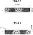
- Arrows in Fig. 5A and Fig. 5B indicate a moving route of the plasma torch 7.
- Each of the plasma torches 7 turns clockwise about 62.5mm inside from a mold wall of the mold 2.
- the output of each plasma torch 7 is, for example, 750kW.
- an electromagnetic stirring device 8 is disposed on a side of the mold 2 and used to stir at least the melt surface of the molten metal 12 inside the mold 2 by electromagnetic induction.
- electromagnetic stirring caused by the electromagnetic stirring device 8, a horizontally rotating flow (turning flow) is generated on or near the melt surface of the molten metal 12.
- the molten metal 12 having a higher temperature, residing at the long side parts of the mold 2 is transferred to the short side and the corner parts of the mold 2, where the solidified shell 13 tends to grow. This mitigates temperature rise of the molten metal 12 at the long side parts of the mold 2, where the plasma torch 7 stays longer, and temperature drop of the molten metal 12 at the short side and the corner parts of the mold 2, where the plasma torch 7 stays shorter.
- a direction of the turning flow at least on the melt surface of the molten metal 12 may be the same as the turning direction of the plasma torch 7 or a direction opposite thereto. However, turning at least the melt surface of the molten metal 12 in a direction opposite to the turning direction of the plasma torch 7 can reduce a fluctuation range in a surface temperature of the slab 11.
- the slab 11 having a large size When the slab 11 having a large size is continuously cast, it is required to accelerate a flow rate of the molten metal 12 by a strong stirring force in order to transfer heat to the entire melt surface by the electromagnetic stirring.
- Fig. 7A and Fig. 7B each depicting a model diagram of the mold 2 seen from above, when the slab 11 having a small size of, for example, 125 ⁇ 375mm is continuously cast by the plasma arc melting, the entire melt surface can be heated by a single plasma torch 7 small in output owing to a small area of the melt surface. Further, since the slab 11 is thin, the growth of the solidified shell 13 can be suppressed at the short side and the corner parts of the mold 2 by reciprocating the plasma torch 7 on the same line. It is noted that arrows in Fig. 7A and Fig. 7B indicate a moving route of the plasma torch 7. The output of the plasma torch 7 is, for example, 200 to 250kW.
- Fig. 8 depicting a model diagram of the mold 2 seen from above, when the slab 11 having a small size is continuously cast, the heat can be still transferred to the entire melt surface by the turning flow of the molten metal 12 having a slow flow rate due to a weak stirring force of the electromagnetic stirring.
- the number, an output, and a moving pattern of the plasma torch 7 required for smoothing a casting surface depend on the size of the slab 11 to be cast. Further, the stirring force of the electromagnetic stirring required for smoothing a casting surface depends on the size of the slab 11 to be cast.
- the present inventors as a result of trial-and-error attempts to cast the slab 11 having an excellent casting surface condition, have found that it is possible to cast the slab 11 having an excellent casting surface condition by adjusting a torch moving cycle, an average heat input quantity, and a molten metal advection time within a predetermined numerical value range.
- the slab 11 having an excellent casting surface condition can be cast by adjusting the torch moving cycle to 20 sec or more and 40 sec or less, the average heat input quantity to 1.0MW/m 2 or more and 2.0MW/m 2 or less, and the molten metal advection time to 3.5 sec or less.
- the torch moving cycle is a time required for the plasma torch 7 to complete a single round of movement in a predetermined moving pattern over the melt surface. Specifically, the torch moving cycle is obtained by dividing a moving distance of the plasma torch 7 per round by an average moving speed of the plasma torch 7.
- Fig. 5A and Fig. 5B when the slab 11 having a large size is cast, two plasma torches 7 are each rotationally moved at a predetermined speed over the melt surface.
- the torch moving cycle is a time required for the plasma torch 7 to complete one rotation.
- Fig. 7A and Fig. 7B when the slab 11 having a small size is cast, the plasma torch 7 is reciprocally moved at a predetermined speed over the melt surface.
- the torch moving cycle is a time required for the plasma torch 7 to complete one reciprocating motion.
- a length of the long side of the slab 11 in a horizontal cross section is denoted as 2W.
- the mold 2 shown in Fig. 9 is for casting the slab 11 having a large size, and corresponds to the mold 2 shown in Fig. 5A and Fig. 5B .
- the mold 2 shown in Fig. 10 is for casting the slab 11 having a small size, and corresponds to the mold 2 shown in Fig. 7A and Fig. 7B .
- the nonuniformity caused by the temporal change and the spatial variation in the heat input quantity to the melt surface of the molten metal 12 can be reduced by setting the torch moving cycle T to 20 sec or more and 40 sec or less.
- the torch moving cycle T was calculated by flow and solidification calculation in order to obtain the slab 11 having an excellent casting surface over the entire periphery. The result is shown in Table 1.
- Table 1 Slab width 2W[mm] Number of plasma torch A[-] Average moving speed Vt[mm/sec] Torch moving cycle T[sec] 750 1 50 30 1000 1 50 40 1000 2 50 20 1250 2 50 25 1500 2 50 30
- a maximum value of the average moving speed Vt is about 50mm/sec. Further, it is estimated that a limit value of the slab width up to which the single plasma torch 7 can be used for casting is about 1000mm. Based on these, it was found that the slab 11 having an excellent casting surface over the entire periphery could be obtained by setting the torch moving cycle T to 20 sec or more and 40 sec or less.
- the average heat input quantity is obtained by dividing the initial solidification portion 15 (a portion where the molten metal 12 is initially solidified upon contacting with the mold 2) (see Fig. 3A and Fig. 3B ) into a plurality of portions in a peripheral direction of the mold 2, and calculating an average of heat input quantities to each of the portions in a length direction of the corresponding portion along the mold 2.
- the initial solidification portion 15 is divided into a total of twelve portions 15a along the inner periphery of the mold 2, consisting of corners (1) to (4), long sides 1/4 (1) and (2), long sides 1/2 (1) and (2), long sides 3/4 (1) and (2), and short sides (1) and (2). Then the average heat input quantity is obtained in each of the portions 15a.
- the growth of the solidified shell 13 near the melt surface of the molten metal 12 is significantly influenced by the heat input condition to the initial solidification portion 15. As shown in Fig. 3A , if the heat input to the initial solidification portion 15 is excessive, the "tearing-off defect" occurs. On the other hand, as shown in Fig. 3B , if the heat input to the initial solidification portion 15 is not sufficient, the "molten metal-covering defect" occurs.
- the nonuniformity in the heat input quantity over the entire periphery of peripheral parts of the melt surface of the molten metal 12 can be reduced by setting the average heat input quantity to 1.0MW/m 2 or more and 2.0MW /m 2 or less.
- Case (1) shows the average heat input quantities in a case where the slab 11 having a large size of 250mm x 1500mm is cast using two plasma torches 7 each having an output of 750kW, as shown in Fig. 5A .
- Case (2) shows the average heat input quantities in a case where the slab 11 having a small size of 125mm x 375mm is cast using the single plasma torch 7 having an output of 200kW, as shown in Fig. 7A .
- a slab average heat input quantity obtained by multiplying the average heat input quantity by a correction value may be used instead of the average heat input quantity.
- the correction value herein is a value based on a length of the mold 2 surrounding a torch heating region.
- the torch heating region is a region of the melt surface of the molten metal 12, which is heated by the individual plasma torch 7.
- the torch heating region 17 is surrounded on its three sides with the mold 2.
- the torch heating region 17 is surrounded on its four sides with the mold 2. Consequently, a cooling capacity of the mold 2 is larger in the torch heating region 17 surrounded on its four sides with the mold 2 than the one surrounded on its three sides with the mold 2.
- the slab average heat input quantity obtained by correcting the average heat input quantity with a correction value ⁇ is used.
- the correction value ⁇ is calculated from the following formula (1) using lengths of the long side 2W (mm) and the short side t (mm) of the mold 2 shown in Fig. 7A .
- Case (2) when the output value of the plasma torch 7 is multiplied by the correction value ⁇ , the output becomes 250kW.
- the slab average heat input quantities obtained by correcting the average heat input quantities in Case (2) with the correction value ⁇ are shown as Case (3) in Fig. 12 .
- the growth of the solidified shell 13 near the melt surface of the molten metal 12 can be suitably suppressed by setting the slab average heat input quantity in each portion 15a to 1.0MW/m 2 or more and 2.0MW/m 2 or less. By this, the slab 11 having an excellent casting surface can be obtained.
- the molten metal advection time is a time required for the molten metal 12 stirred electromagnetically to travel a length of the torch heating region 17 (torch effective heating width) along the long side direction of the mold 2.
- the molten metal advection time is a value obtained by dividing the torch effective heating width by an average flow rate of the molten metal 12 while being transferred by electromagnetic stirring.
- the torch heating region 17 of each plasma torch 7 is half of the melt surface of the molten metal 12.
- the torch effective heating width in this case is one half of the length of the long side of the mold 2.
- the torch heating region 17 of the plasma torch 7 is all the melt surface of the molten metal 12.
- the torch effective heating width in this case is the entire length of the long side of the mold 2.
- Fig. 13 depicting a model diagram of the mold 2 seen from above
- the melt surface of the molten metal 12 on the right side of the figure becomes apart from the plasma torch 7, thereby having a lower temperature.
- the melt surface of the molten metal 12 on the left side having a higher temperature, is transferred to the melt surface on the right side by electromagnetic stirring. This mitigates the temperature drop of the molten metal 12 as compared to a case where the electromagnetic stirring is not performed and can thus uniformize the surface temperature of the slab.
- a degree of change in the surface temperature of the slab 11 over time also varies. Specifically, as the molten metal advection time becomes shorter, a temporal change of the surface temperature of the slab 11 becomes smaller, and eventually, the surface temperature of the slab 11 can be uniformized.
- the surface temperature of the slab 11 can be uniformized by setting the molten metal advection time Tm to 3.5 sec or less.
- the molten metal advection time required for obtaining the slab 11 having an excellent casting surface over the entire periphery was calculated by flow and solidification calculation.
- the molten metal advection time was obtained by using an average value of the flow rates (absolute values) in the x-axis direction in a range of -2L / 5 ⁇ x ⁇ 2L / 5 at positions 10mm away from the inner surface of the mold 2.
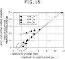
- Fig. 15 shows a relation between the molten metal advection time and an index of occurrence frequency of irregularities.
- Case (1) represents calculation results in the case where the slab 11 having a large size of 250mm x 1500mm was cast using two plasma torches 7 each having an output of 750kW, as shown in Fig. 5A .
- Case (2) represents calculation results in the case where the slab 11 having a small size of 125mm x 375mm was cast using the single plasma torch 7 having an output of 200kW, as shown in Fig. 7A .
- Case (3) represents calculation results of Case (2) after correcting the output value of the plasma torch 7 in Case (2) by the correction value to 250kW.
- the torch moving cycle representing a time required for the plasma torch 7 to complete a single round of movement in the predetermined moving pattern is set to 20 sec or more and 40 sec or less. This can reduce the nonuniformity caused by the temporal change and the spatial variation in the heat input quantity to the melt surface of the molten metal 12 due to a movement of the plasma torch 7. Further, the average heat input quantity to the individual portion 15a resulting from dividing the initial solidification portion 15 into the plurality of the portions 15a in the peripheral direction of the mold 2 is set to 1.0MW/m 2 or more and 2.0MW/m 2 or less.
- the molten metal advection time representing a time required for the molten metal 12 to travel the length of the torch heating region 17 along the long side direction of the mold 2 is set to 3.5 sec or less. This can uniformize the surface temperature of the slab 11. By uniformizing the heat input quantity over the entire periphery of the peripheral parts of the melt surface of the molten metal 12 in this manner, it becomes possible to cast the slab 11 having an excellent casting surface condition.
Landscapes
- Engineering & Computer Science (AREA)
- Mechanical Engineering (AREA)
- Physics & Mathematics (AREA)
- Plasma & Fusion (AREA)
- General Engineering & Computer Science (AREA)
- Spectroscopy & Molecular Physics (AREA)
- Continuous Casting (AREA)
Abstract
Description
- The present invention relates to a continuous casting device for a slab made of titanium or a titanium alloy.
- Continuous casting of an ingot is commonly performed by injecting metal melted by vacuum arc melting or electron beam melting into a bottomless mold and withdrawing the metal downward while being solidified.
-
Patent Document 1 discloses an automatic control method for plasma melting casting, in which titanium or a titanium alloy is subjected to plasma arc melting in an argon gas atmosphere and injected into a mold for solidification. Performing the plasma arc melting in an inert gas atmosphere, unlike the electron beam melting in vacuum, allows casting of not only pure titanium, but also a titanium alloy. - Patent Document 1: Japanese Patent No.
3077387 - However, if an ingot has irregularities or flaws on a casting surface after casting, a pretreatment, such as cutting the surface, is required before rolling. This causes a reduction in material utilization and an increase in the number of work processes. Thus, there is demand for an ingot casting without causing irregularities or flaws on a casting surface.
- An object of the present invention is to provide a continuous casting device for a slab made of titanium or a titanium alloy, capable of casting a slab having an excellent casting surface condition.
- The present inventors, as a result of trial-and-error attempts to solve the above-mentioned problem, have found that it is possible to cast a slab having an excellent casting surface condition by adjusting a torch moving cycle, an average heat input quantity, and a molten metal advection time within a predetermined numerical value range.
- Specifically, the continuous casting device of the present invention is a device for continuously casting a slab made of titanium or a titanium alloy by injecting molten metal prepared by melting titanium or a titanium alloy into a bottomless mold having a rectangular cross section and withdrawing the molten metal downward while being solidified, the device being characterized by comprising:
- a plasma torch for heating a melt surface of the molten metal in the mold while moving over the melt surface of the molten metal in a predetermined moving pattern, the plasma torch being disposed above the mold; and
- an electromagnetic stirring device for stirring at least the melt surface of the molten metal by electromagnetic stirring, the electromagnetic stirring device being disposed on a side of the mold, and by having:
- a torch moving cycle T of 20 sec or more and 40 sec or less, the torch moving cycle T being a time required for the plasma torch to complete a single round of movement in the predetermined moving pattern and calculated by T = 4W / (A · Vt), where 2W represents a length of a long side of the slab in a horizontal cross section, A represents the number of the plasma torch, and Vt represents an average moving speed of the plasma torch while moving in the predetermined moving pattern;
- an average heat input quantity of 1.0MW/m2 or more and 2.0MW/m2 or less, the average heat input quantity being obtained by dividing an initial solidification portion, where the molten metal is initially solidified upon contacting with the mold, into a plurality of portions in a peripheral direction of the mold, and calculating an average of heat input quantities to each of the portions in a length direction of the corresponding portion along the mold; and
- a molten metal advection time Tm of 3.5 sec or less, the molten metal advection time being calculated by Tm = L / Vm, where L represents a length of a torch heating region along a long side direction of the mold, the torch heating region being a region of the melt surface of the molten metal, which is heated by the individual plasma torch, and Vm represents an average flow rate of the molten metal while traveling the length L by electromagnetic stirring, and representing a time required for the molten metal to travel the length L of the torch heating region along the long side direction of the mold. Advantageous Effects of Invention
- According to the present invention, the torch moving cycle, a time required for the plasma torch to complete a single round of movement in the predetermined moving pattern, is set to 20 sec or more and 40 sec or less. This can reduce nonuniformity caused by a temporal change and a spatial variation in heat input quantities to the melt surface of the molten metal due to a movement of the plasma torch. Further, the average heat input quantity to the individual portion resulting from dividing the initial solidification portion into the plurality of portions in the peripheral direction of the mold is set to 1.0MW/m2 or more and 2.0MW/m2 or less. This can reduce the nonuniformity in the heat input quantities over the entire periphery of peripheral parts of the melt surface of the molten metal. Finally, the molten metal advection time representing a time required for the molten metal to travel the length of the torch heating region along the long side direction of the mold is set to 3.5 sec or less. This can uniformize surface temperatures of the slab. By uniformizing the heat input quantities over the entire periphery of the peripheral parts of the melt surface of the molten metal in this manner, it becomes possible to cast the slab having an excellent casting surface condition.
-
- [
Fig. 1] Fig. 1 is a perspective view of a continuous casting device. - [
Fig. 2] Fig. 2 is a cross-section view of the continuous casting device. - [
Fig. 3A] Fig. 3A is an explanatory diagram illustrating a causing mechanism of a surface defect. - [
Fig. 3B] Fig. 3B is an explanatory diagram illustrating a causing mechanism of a surface defect. - [
Fig. 4A] Fig. 4A is an image of a slab surface. - [
Fig. 4B] Fig. 4B is an image of a slab surface. - [
Fig. 5A] Fig. 5A is a model diagram of a mold, seen from above. - [
Fig. 5B] Fig. 5B is a model diagram of the mold, seen from above. - [
Fig. 6] Fig. 6 is a model diagram of a mold, seen from above. - [
Fig. 7A] Fig. 7A is a model diagram of a mold, seen from above. - [
Fig. 7B] Fig. 7B is a model diagram of the mold, seen from above. - [
Fig. 8] Fig. 8 is a model diagram of a mold, seen from above. - [
Fig. 9] Fig. 9 is a model diagram of a mold, seen from above. - [
Fig. 10] Fig. 10 is a model diagram of a mold, seen from above. - [
Fig. 11] Fig. 11 is a model diagram of a mold, seen from above. - [
Fig. 12] Fig. 12 is a graph showing an average heat input quantity at an individual portion resulting from dividing an initial solidification portion into a plurality of portions. - [
Fig. 13] Fig. 13 is a model diagram of a mold, seen from above. - [
Fig. 14] Fig. 14 is a model diagram of a mold, seen from above. - [
Fig. 15] Fig. 15 is a graph showing a relation between a molten metal advection time and an index of occurrence frequency of irregularities. - Hereinafter, preferred embodiments of the present invention will be described with reference to the drawings.
- A continuous casting device (continuous casting device) 1 for a slab made of titanium or a titanium alloy according to the present embodiment is a continuous casting device for continuously casting a slab made of titanium or a titanium alloy by injecting molten metal of titanium or a titanium alloy subjected to plasma arc melting into a bottomless mold having a rectangular cross section and withdrawing the molten metal downward while being solidified. This
continuous casting device 1 comprises, as shown inFig. 1 as a perspective view andFig. 2 as a cross-section view, amold 2, acold hearth 3, asource charging device 4, aplasma torch 5, astarting block 6, and aplasma torch 7, anelectromagnetic stirring device 8, and a controller (controlling device) 9. It is noted that theelectromagnetic stirring device 8 and thecontroller 9 are not shown inFig. 1 . Thecontinuous casting device 1 is surrounded by an inert gas atmosphere containing argon gas, helium gas, and the like. - The
source charging device 4 supplies a source of titanium or a titanium alloy, such as sponge titanium and scrap, into thecold hearth 3. Theplasma torch 5 is disposed above thecold hearth 3 and melts the source inside thecold hearth 3 by generating plasma arcs. Thecold hearth 3 injectsmolten metal 12 having the source melted into themold 2 from an injectingportion 3a at a predetermined flow rate. - The
mold 2 is made of copper and formed in a bottomless shape having a rectangular cross section. At least a part of a wall portion of themold 2 formed in a rectangular cylindrical shape is configured to circulate water inside the wall portion for cooling. The startingblock 6 is movable in an up and down direction by a drive portion not shown, and able to block a lower side opening of themold 2. Theplasma torch 7 is disposed above themold 2 and configured to move above a melt surface ofmolten metal 12 in a predetermined moving pattern by a moving means not shown, thereby heating the melt surface of themolten metal 12 injected into themold 2 by plasma arcs. Thecontroller 9 controls the movement of theplasma torch 7. - The
electromagnetic stirring device 8 is a device having a coil iron core wound by an EMS coil and disposed on a side of themold 2. It stirs at least the melt surface of themolten metal 12 inside themold 2 by electromagnetic stirring driven by alternating current. Thecontroller 9 controls the electromagnetic stirring of theelectromagnetic stirring device 8. - In the foregoing configuration, solidification of the
molten metal 12 injected into themold 2 begins from a contact surface between themolten metal 12 and themold 2 having a water-cooling system. Then, as thestarting block 6 blocking the lower side opening of themold 2 is lowered at a predetermined speed, aslab 11 in a rectangular cylindrical shape formed by solidifying themolten metal 12 is continuously cast while being withdrawn downward from themold 2. - In this process, it is difficult to cast a titanium alloy using electron beam melting in a vacuum atmosphere since trace components in the titanium alloy would evaporate. In contrast, it is possible to cast not only pure titanium, but also a titanium alloy using plasma arc melting in an inert gas atmosphere.
- Further, the
continuous casting device 1 may comprise a flux supplying device for supplying flux in a solid phase or a liquid phase to the melt surface of themolten metal 12 inside themold 2. In this process, it is difficult to supply the flux to themolten metal 12 inside themold 2 using the electron beam melting in a vacuum atmosphere since the flux would be scattered. In contrast, the plasma arc melting in an inert gas atmosphere has an advantage of being able to supply the flux to themolten metal 12 inside themold 2. - When a
slab 11 made of titanium or a titanium alloy is continuously cast, irregularities or flaws generated on a surface of the slab 11 (casting surface) would cause a surface defect in a next rolling process. Thus, such irregularities or flaws on the surface of theslab 11 must be removed before rolling by cutting or the like. However, this would decrease material utilization and increase the number of work processes, thereby causing an increase in cost. As such, there is demand for the casting of theslab 11 without causing irregularities or flaws on the casting surface. -
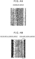
Fig. 3A and Fig. 3B are explanatory diagrams each illustrating a causing mechanism of a surface defect. In the vicinity of a border between themold 2 and themolten metal 12, themold 2 contacts with a surface of a solidifiedshell 13 only near the melt surface of the molten metal 12 (a region extending from the melt surface to an about 10mm depth) that is heated by the plasma arcs or the electron beam. In a region deeper than this contact region, theslab 11 undergoes thermal shrinkage, thus anair gap 14 is generated between theslab 11 and themold 2. Then, as shown inFig. 3A , if a heat input is excessive to an initial solidification portion 15 (a portion of themolten metal 12 initially solidified by contacting to the mold 2) located in periphery parts of the melt surface of themolten metal 12, the solidifiedshell 13 becomes too thin and falls short of strength, thereby causing a "tearing-off defect", in which a surface portion of the solidifiedshell 13 is torn off. On the other hand, as shown inFig. 3B , if the heat input to theinitial solidification portion 15 is not sufficient, there occurs a "molten metal-covering defect", in which the solidifiedshell 13 that has grown (become thick) is covered with themolten metal 12. Images of ingot surfaces having the "tearing-off defect" and the "molten metal-covering defect" are shown inFig. 4A and Fig. 4B , respectively. - Thus, it is speculated that a heat input/output condition applying to the
initial solidification portion 15 near the melt surface of themolten metal 12 would have a great impact on a casting surface condition. Accordingly, it is expected that theslab 11 having an excellent casting surface can be obtained by appropriately controlling the heat input/output condition applying to theinitial solidification portion 15 near the melt surface of themolten metal 12. - However, as shown in
Fig. 5A and Fig. 5B , each depicting a model diagram of themold 2 seen from above, when theslab 11 having a large size of, for example, 250 × 1500mm is continuously cast by the plasma arc melting, there is a limitation to a heating range of theplasma torch 7. Thus, heating the entire melt surface requires a plurality of the plasma torches 7 having a large output. InFig. 5A and Fig. 5B , twoplasma torches 7 having a large output are used. Further, since theslab 11 is thick, theplasma torch 7 needs to be rotationally moved along themold 2 in order to suppress the growth of the solidifiedshell 13 at short side and corner parts of themold 2. Arrows inFig. 5A and Fig. 5B indicate a moving route of theplasma torch 7. Each of the plasma torches 7 turns clockwise about 62.5mm inside from a mold wall of themold 2. The output of eachplasma torch 7 is, for example, 750kW. - Since a staying time of the
plasma torch 7 at long side parts of themold 2 is long, the heat input to theinitial solidification portion 15 becomes large, resulting in forming the thin solidifiedshell 13. On the other hand, the staying time of theplasma torch 7 at the short side and the corner parts of themold 2 is short, thus the heat input to theinitial solidification portion 15 becomes insufficient, and accordingly, the solidifiedshell 13 has grown (become thick). Consequently, the solidification takes place unevenly depending on a position of theslab 11, leading to deterioration of the casting surface condition. - Thus, as shown in
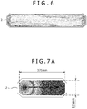
Fig. 6 depicting a model diagram of themold 2 seen from above, anelectromagnetic stirring device 8, not shown, is disposed on a side of themold 2 and used to stir at least the melt surface of themolten metal 12 inside themold 2 by electromagnetic induction. By electromagnetic stirring caused by theelectromagnetic stirring device 8, a horizontally rotating flow (turning flow) is generated on or near the melt surface of themolten metal 12. By this turning flow, themolten metal 12 having a higher temperature, residing at the long side parts of themold 2, is transferred to the short side and the corner parts of themold 2, where the solidifiedshell 13 tends to grow. This mitigates temperature rise of themolten metal 12 at the long side parts of themold 2, where theplasma torch 7 stays longer, and temperature drop of themolten metal 12 at the short side and the corner parts of themold 2, where theplasma torch 7 stays shorter. - It is noted that a direction of the turning flow at least on the melt surface of the
molten metal 12 may be the same as the turning direction of theplasma torch 7 or a direction opposite thereto. However, turning at least the melt surface of themolten metal 12 in a direction opposite to the turning direction of theplasma torch 7 can reduce a fluctuation range in a surface temperature of theslab 11. - When the
slab 11 having a large size is continuously cast, it is required to accelerate a flow rate of themolten metal 12 by a strong stirring force in order to transfer heat to the entire melt surface by the electromagnetic stirring. - On the other hand, as shown in
Fig. 7A andFig. 7B , each depicting a model diagram of themold 2 seen from above, when theslab 11 having a small size of, for example, 125 × 375mm is continuously cast by the plasma arc melting, the entire melt surface can be heated by asingle plasma torch 7 small in output owing to a small area of the melt surface. Further, since theslab 11 is thin, the growth of the solidifiedshell 13 can be suppressed at the short side and the corner parts of themold 2 by reciprocating theplasma torch 7 on the same line. It is noted that arrows inFig. 7A andFig. 7B indicate a moving route of theplasma torch 7. The output of theplasma torch 7 is, for example, 200 to 250kW. - Further, as shown in
Fig. 8 depicting a model diagram of themold 2 seen from above, when theslab 11 having a small size is continuously cast, the heat can be still transferred to the entire melt surface by the turning flow of themolten metal 12 having a slow flow rate due to a weak stirring force of the electromagnetic stirring. - As described above, the number, an output, and a moving pattern of the
plasma torch 7 required for smoothing a casting surface depend on the size of theslab 11 to be cast. Further, the stirring force of the electromagnetic stirring required for smoothing a casting surface depends on the size of theslab 11 to be cast. - On the basis of the premise above, the present inventors, as a result of trial-and-error attempts to cast the
slab 11 having an excellent casting surface condition, have found that it is possible to cast theslab 11 having an excellent casting surface condition by adjusting a torch moving cycle, an average heat input quantity, and a molten metal advection time within a predetermined numerical value range. - Specifically, it was found that the
slab 11 having an excellent casting surface condition can be cast by adjusting the torch moving cycle to 20 sec or more and 40 sec or less, the average heat input quantity to 1.0MW/m2 or more and 2.0MW/m2 or less, and the molten metal advection time to 3.5 sec or less. - The torch moving cycle is a time required for the
plasma torch 7 to complete a single round of movement in a predetermined moving pattern over the melt surface. Specifically, the torch moving cycle is obtained by dividing a moving distance of theplasma torch 7 per round by an average moving speed of theplasma torch 7. - As shown in
Fig. 5A and Fig. 5B , when theslab 11 having a large size is cast, twoplasma torches 7 are each rotationally moved at a predetermined speed over the melt surface. The torch moving cycle is a time required for theplasma torch 7 to complete one rotation. Further, as shown inFig. 7A andFig. 7B , when theslab 11 having a small size is cast, theplasma torch 7 is reciprocally moved at a predetermined speed over the melt surface. The torch moving cycle is a time required for theplasma torch 7 to complete one reciprocating motion. - As shown in
Fig. 9 and Fig. 10 , each depicting a model diagram of themold 2 seen from above, a length of the long side of theslab 11 in a horizontal cross section (slab width) is denoted as 2W. It is noted that themold 2 shown inFig. 9 is for casting theslab 11 having a large size, and corresponds to themold 2 shown inFig. 5A and Fig. 5B . On the other hand, themold 2 shown inFig. 10 is for casting theslab 11 having a small size, and corresponds to themold 2 shown inFig. 7A andFig. 7B . Further, the torch moving cycle T is calculated by T = 4W / (A · Vt), where A represents the number of theplasma torch 7 and Vt represents an average moving speed of theplasma torch 7 while moving in the predetermined moving pattern. - As shown in
Fig. 5A, Fig. 5B ,Fig. 7A , andFig. 7B , when an attention is paid to a given location on the melt surface of themolten metal 12, themovable plasma torch 7 is moving toward and away from that location. Thus, a heat input quantity to the given location changes over time. Further, when an attention is paid to the entire melt surface of themolten metal 12, a location near theplasma torch 7, thus having a high heat input quantity and a location far from theplasma torch 7, thus having a low heat input quantity change as theplasma torch 7 moves. Consequently, the movement of theplasma torch 7 causes a temporal change and a spatial variation in the heat input quantity to the melt surface of themolten metal 12, thereby generating nonuniformity in the heat input quantity. - However, the nonuniformity caused by the temporal change and the spatial variation in the heat input quantity to the melt surface of the
molten metal 12 can be reduced by setting the torch moving cycle T to 20 sec or more and 40 sec or less. - The torch moving cycle T was calculated by flow and solidification calculation in order to obtain the
slab 11 having an excellent casting surface over the entire periphery. The result is shown in Table 1.[Table 1] Slab width 2W[mm]Number of plasma torch A[-] Average moving speed Vt[mm/sec] Torch moving cycle T[sec] 750 1 50 30 1000 1 50 40 1000 2 50 20 1250 2 50 25 1500 2 50 30 - A maximum value of the average moving speed Vt is about 50mm/sec. Further, it is estimated that a limit value of the slab width up to which the
single plasma torch 7 can be used for casting is about 1000mm. Based on these, it was found that theslab 11 having an excellent casting surface over the entire periphery could be obtained by setting the torch moving cycle T to 20 sec or more and 40 sec or less. - The average heat input quantity is obtained by dividing the initial solidification portion 15 (a portion where the
molten metal 12 is initially solidified upon contacting with the mold 2) (seeFig. 3A and Fig. 3B ) into a plurality of portions in a peripheral direction of themold 2, and calculating an average of heat input quantities to each of the portions in a length direction of the corresponding portion along themold 2. - In the present embodiment, as shown in
Fig. 11 depicting a model diagram of themold 2 seen from above, theinitial solidification portion 15 is divided into a total of twelveportions 15a along the inner periphery of themold 2, consisting of corners (1) to (4),long sides 1/4 (1) and (2),long sides 1/2 (1) and (2),long sides 3/4 (1) and (2), and short sides (1) and (2). Then the average heat input quantity is obtained in each of theportions 15a. - As mentioned above, the growth of the solidified
shell 13 near the melt surface of themolten metal 12 is significantly influenced by the heat input condition to theinitial solidification portion 15. As shown inFig. 3A , if the heat input to theinitial solidification portion 15 is excessive, the "tearing-off defect" occurs. On the other hand, as shown inFig. 3B , if the heat input to theinitial solidification portion 15 is not sufficient, the "molten metal-covering defect" occurs. - However, the nonuniformity in the heat input quantity over the entire periphery of peripheral parts of the melt surface of the
molten metal 12 can be reduced by setting the average heat input quantity to 1.0MW/m2 or more and 2.0MW /m2 or less. - The average heat input quantity was calculated by flow and solidification calculation in order to obtain the
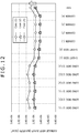
slab 11 having an excellent casting surface over the entire periphery. The result is shown inFig. 12 . In this figure, Case (1) shows the average heat input quantities in a case where theslab 11 having a large size of 250mm x 1500mm is cast using twoplasma torches 7 each having an output of 750kW, as shown inFig. 5A . Further, Case (2) shows the average heat input quantities in a case where theslab 11 having a small size of 125mm x 375mm is cast using thesingle plasma torch 7 having an output of 200kW, as shown inFig. 7A . - From
Fig. 12 , it was found that theslab 11 having an excellent casting surface over the entire periphery could be obtained by setting the average heat input quantity to 1.0MW/m2 or more and 2.0MW/m2 or less. - It is noted that, instead of the average heat input quantity, a slab average heat input quantity obtained by multiplying the average heat input quantity by a correction value may be used. The correction value herein is a value based on a length of the
mold 2 surrounding a torch heating region. The torch heating region is a region of the melt surface of themolten metal 12, which is heated by theindividual plasma torch 7. - As shown in
Fig. 9 , when theslab 11 having a large size is cast using twoplasma torches 7, half of the melt surface of themolten metal 12 is thetorch heating region 17 that is heated by eachplasma torch 7. On the other hand, as shown inFig. 10 , when theslab 11 having a small size is cast using thesingle plasma torch 7, all the melt surface of themolten metal 12 is thetorch heating region 17 that is heated by theplasma torch 7. - As shown in
Fig. 9 , when twoplasma torches 7 are used, thetorch heating region 17 is surrounded on its three sides with themold 2. On the other hand, as shown inFig. 10 , when thesingle plasma torch 7 is used, thetorch heating region 17 is surrounded on its four sides with themold 2. Consequently, a cooling capacity of themold 2 is larger in thetorch heating region 17 surrounded on its four sides with themold 2 than the one surrounded on its three sides with themold 2. Thus, when thesingle plasma torch 7 is used, the slab average heat input quantity obtained by correcting the average heat input quantity with a correction value α is used. The correction value α is calculated from the following formula (1) using lengths of thelong side 2W (mm) and the short side t (mm) of themold 2 shown inFig. 7A .
- In Case (2), when the output value of the
plasma torch 7 is multiplied by the correction value α, the output becomes 250kW. The slab average heat input quantities obtained by correcting the average heat input quantities in Case (2) with the correction value α are shown as Case (3) inFig. 12 . The growth of the solidifiedshell 13 near the melt surface of themolten metal 12 can be suitably suppressed by setting the slab average heat input quantity in eachportion 15a to 1.0MW/m2 or more and 2.0MW/m2 or less. By this, theslab 11 having an excellent casting surface can be obtained. - The molten metal advection time is a time required for the
molten metal 12 stirred electromagnetically to travel a length of the torch heating region 17 (torch effective heating width) along the long side direction of themold 2. Specifically, the molten metal advection time is a value obtained by dividing the torch effective heating width by an average flow rate of themolten metal 12 while being transferred by electromagnetic stirring. - As shown in
Fig. 9 , when theslab 11 having a large size is cast, thetorch heating region 17 of eachplasma torch 7 is half of the melt surface of themolten metal 12. Thus, the torch effective heating width in this case is one half of the length of the long side of themold 2. On the other hand, as shown inFig. 10 , when theslab 11 having a small size is cast, thetorch heating region 17 of theplasma torch 7 is all the melt surface of themolten metal 12. Thus, the torch effective heating width in this case is the entire length of the long side of themold 2. - The molten metal advection time Tm is calculated by Tm = L / Vm, where L represents the torch effective heating width and Vm represents the average flow rate of the
molten metal 12 while traveling the torch effective heating width L by electromagnetic stirring. - As shown in
Fig. 13 depicting a model diagram of themold 2 seen from above, when theplasma torch 7 moves on the melt surface to the left side of the figure, the melt surface of themolten metal 12 on the right side of the figure becomes apart from theplasma torch 7, thereby having a lower temperature. To prevent this, as shown by arrows, the melt surface of themolten metal 12 on the left side, having a higher temperature, is transferred to the melt surface on the right side by electromagnetic stirring. This mitigates the temperature drop of themolten metal 12 as compared to a case where the electromagnetic stirring is not performed and can thus uniformize the surface temperature of the slab. - However, as the molten metal advection time required for the
molten metal 12 to travel the torch effective heating width varies, a degree of change in the surface temperature of theslab 11 over time also varies. Specifically, as the molten metal advection time becomes shorter, a temporal change of the surface temperature of theslab 11 becomes smaller, and eventually, the surface temperature of theslab 11 can be uniformized. - Remarkably, the surface temperature of the
slab 11 can be uniformized by setting the molten metal advection time Tm to 3.5 sec or less. - The molten metal advection time required for obtaining the
slab 11 having an excellent casting surface over the entire periphery was calculated by flow and solidification calculation. In this calculation, as shown inFig. 14 depicting a model diagram of themold 2 seen from above, the molten metal advection time was obtained by using an average value of the flow rates (absolute values) in the x-axis direction in a range of -2L / 5 ≤ x ≤ 2L / 5 at positions 10mm away from the inner surface of themold 2. -
Fig. 15 shows a relation between the molten metal advection time and an index of occurrence frequency of irregularities. In this figure, Case (1) represents calculation results in the case where theslab 11 having a large size of 250mm x 1500mm was cast using twoplasma torches 7 each having an output of 750kW, as shown inFig. 5A . Further, Case (2) represents calculation results in the case where theslab 11 having a small size of 125mm x 375mm was cast using thesingle plasma torch 7 having an output of 200kW, as shown inFig. 7A . Finally, Case (3) represents calculation results of Case (2) after correcting the output value of theplasma torch 7 in Case (2) by the correction value to 250kW. - Further, in this relation diagram, calculation results are plotted with respect to a stirring force of electromagnetic stirring while being changed. It is noted that as the stirring force of electromagnetic stirring becomes stronger, the flow rate of the
molten metal 12 is increased more and the molten metal advection time is made shorter. Further, the smaller the index of occurrence frequency of irregularities is, the more the casting surface condition becomes excellent. Thus, a target range of the index of occurrence frequency of irregularities was set to 10 or less. - Based on
Fig. 15 , it was found that theslab 11 having an excellent casting surface over the entire periphery could be obtained by setting the molten metal advection time to 3.5 sec or less. - As described hereinabove, in the
continuous casting device 1 for the slab made of titanium or a titanium alloy according to the present embodiment, the torch moving cycle representing a time required for theplasma torch 7 to complete a single round of movement in the predetermined moving pattern is set to 20 sec or more and 40 sec or less. This can reduce the nonuniformity caused by the temporal change and the spatial variation in the heat input quantity to the melt surface of themolten metal 12 due to a movement of theplasma torch 7. Further, the average heat input quantity to theindividual portion 15a resulting from dividing theinitial solidification portion 15 into the plurality of theportions 15a in the peripheral direction of themold 2 is set to 1.0MW/m2 or more and 2.0MW/m2 or less. This can reduce the nonuniformity in the heat input quantity over the entire periphery of the peripheral parts of the melt surface of themolten metal 12. Further, the molten metal advection time representing a time required for themolten metal 12 to travel the length of thetorch heating region 17 along the long side direction of themold 2 is set to 3.5 sec or less. This can uniformize the surface temperature of theslab 11. By uniformizing the heat input quantity over the entire periphery of the peripheral parts of the melt surface of themolten metal 12 in this manner, it becomes possible to cast theslab 11 having an excellent casting surface condition. - The embodiments of the present invention are described hereinabove, however, it is obvious that the above embodiments solely serve as examples and are not to limit the present invention. The specific structures and the like of the present invention may be modified and designed according to the needs. Further, the actions and effects of the present invention described in the above embodiments are no more than the most preferable actions and effects achieved by the present invention, thus the actions and effects of the present invention are not limited to those described in the above embodiments of the present invention.
- The present application is based on Japanese Patent Application (Japanese Patent Application No.
2014-83532) filed on Apr. 15, 2014 -
- 1
- Continuous casting device
- 2
- Mold
- 7
- Plasma torch
- 8
- Electromagnetic stirring device
- 9
- Controller
- 12
- Molten metal
- 15
- Initial solidification portion
- 15a
- Portions
- 17
- Torch heating region
Claims (1)
- A continuous casting device for continuously casting a slab made of titanium or a titanium alloy by injecting molten metal prepared by melting titanium or a titanium alloy into a bottomless mold having a rectangular cross section and withdrawing the molten metal downward while being solidified, the device comprising:a plasma torch for heating a melt surface of the molten metal in the mold while moving over the melt surface of the molten metal in a predetermined moving pattern, the plasma torch being disposed above the mold; andan electromagnetic stirring device for stirring at least the melt surface of the molten metal by electromagnetic stirring, the electromagnetic stirring device being disposed on a side of the mold, the device having:a torch moving cycle T of 20 sec or more and 40 sec or less, the torch moving cycle T being a time required for the plasma torch to complete a single round of movement in the predetermined moving pattern and calculated by T = 4W / (A · Vt), where 2W represents a length of a long side of the slab in a horizontal cross section, A represents the number of the plasma torch, and Vt represents an average moving speed of the plasma torch while moving in the predetermined moving pattern;an average heat input quantity of 1.0MW/m2 or more and 2.0MW/m2 or less, the average heat input quantity being obtained by dividing an initial solidification portion, where the molten metal is initially solidified upon contacting with the mold, into a plurality of portions in a peripheral direction of the mold, and calculating an average of heat input quantities to each of the portions in a length direction of the corresponding portion along the mold; anda molten metal advection time Tm of 3.5 sec or less, the molten metal advection time being calculated by Tm = L / Vm, where L represents a length of a torch heating region along a long side direction of the mold, the torch heating region being a region of the melt surface of the molten metal, which is heated by the individual plasma torch, and Vm represents an average flow rate of the molten metal while traveling the length L by electromagnetic stirring, and representing a time required for the molten metal to travel the length L of the torch heating region along the long side direction of the mold.
Applications Claiming Priority (2)
| Application Number | Priority Date | Filing Date | Title |
|---|---|---|---|
| JP2014083532A JP6279963B2 (en) | 2014-04-15 | 2014-04-15 | Continuous casting equipment for slabs made of titanium or titanium alloy |
| PCT/JP2015/058628 WO2015159648A1 (en) | 2014-04-15 | 2015-03-20 | Continuous casting device for slab comprising titanium or titanium alloy |
Publications (3)
| Publication Number | Publication Date |
|---|---|
| EP3132871A1 true EP3132871A1 (en) | 2017-02-22 |
| EP3132871A4 EP3132871A4 (en) | 2017-11-15 |
| EP3132871B1 EP3132871B1 (en) | 2020-04-29 |
Family
ID=54323862
Family Applications (1)
| Application Number | Title | Priority Date | Filing Date |
|---|---|---|---|
| EP15779618.6A Not-in-force EP3132871B1 (en) | 2014-04-15 | 2015-03-20 | Continuous casting device for slab comprising titanium or titanium alloy |
Country Status (4)
| Country | Link |
|---|---|
| US (2) | US20170087625A1 (en) |
| EP (1) | EP3132871B1 (en) |
| JP (1) | JP6279963B2 (en) |
| WO (1) | WO2015159648A1 (en) |
Families Citing this family (3)
| Publication number | Priority date | Publication date | Assignee | Title |
|---|---|---|---|---|
| KR102442579B1 (en) * | 2015-12-01 | 2022-09-08 | 재단법인 포항산업과학연구원 | Manufacturing method of titanium casting parts |
| JP6611331B2 (en) * | 2016-01-07 | 2019-11-27 | 株式会社神戸製鋼所 | Continuous casting method of slab made of titanium or titanium alloy |
| CN109843856B (en) | 2016-05-18 | 2023-05-02 | 米拉蒂治疗股份有限公司 | KRAS G12C inhibitors |
Family Cites Families (13)
| Publication number | Priority date | Publication date | Assignee | Title |
|---|---|---|---|---|
| GB2013542B (en) * | 1978-02-01 | 1982-01-20 | Concast Ag | Continuous casting mould |
| AU5940490A (en) * | 1989-06-26 | 1991-01-17 | Nrc, Inc. | Production of ingots for microcomposite manufacture by plasma melting |
| US5273101A (en) * | 1991-06-05 | 1993-12-28 | General Electric Company | Method and apparatus for casting an arc melted metallic material in ingot form |
| JP3077387B2 (en) | 1992-06-15 | 2000-08-14 | 大同特殊鋼株式会社 | Automatic control plasma melting casting method and automatic control plasma melting casting apparatus |
| EP1254861B1 (en) * | 2000-12-28 | 2008-01-30 | Sumco Corporation | Silicon continuous casting method |
| US6868896B2 (en) * | 2002-09-20 | 2005-03-22 | Edward Scott Jackson | Method and apparatus for melting titanium using a combination of plasma torches and direct arc electrodes |
| RU2448802C2 (en) * | 2007-12-17 | 2012-04-27 | Ротелек | Method and appropriate electromagnetic device for revolution of fused metal in steel mould of continuous casting plant |
| JP5774419B2 (en) * | 2011-09-02 | 2015-09-09 | 株式会社神戸製鋼所 | Continuous casting equipment for slabs made of titanium or titanium alloy |
| JP5730738B2 (en) * | 2011-10-07 | 2015-06-10 | 株式会社神戸製鋼所 | Continuous casting method and continuous casting apparatus for slab made of titanium or titanium alloy |
| JP5878398B2 (en) * | 2012-03-06 | 2016-03-08 | 株式会社神戸製鋼所 | Titanium melting equipment |
| JP5918572B2 (en) * | 2012-03-06 | 2016-05-18 | 株式会社神戸製鋼所 | Continuous casting apparatus and continuous casting method for titanium ingot and titanium alloy ingot |
| JP5896811B2 (en) * | 2012-04-02 | 2016-03-30 | 株式会社神戸製鋼所 | Mold for continuous casting of ingot made of titanium or titanium alloy and continuous casting apparatus provided with the same |
| JP6087155B2 (en) * | 2013-01-23 | 2017-03-01 | 株式会社神戸製鋼所 | Continuous casting method of slab made of titanium or titanium alloy |
-
2014
- 2014-04-15 JP JP2014083532A patent/JP6279963B2/en not_active Expired - Fee Related
-
2015
- 2015-03-20 US US15/127,834 patent/US20170087625A1/en not_active Abandoned
- 2015-03-20 EP EP15779618.6A patent/EP3132871B1/en not_active Not-in-force
- 2015-03-20 WO PCT/JP2015/058628 patent/WO2015159648A1/en not_active Ceased
-
2017
- 2017-09-28 US US15/718,005 patent/US9908174B2/en not_active Expired - Fee Related
Also Published As
| Publication number | Publication date |
|---|---|
| EP3132871B1 (en) | 2020-04-29 |
| WO2015159648A1 (en) | 2015-10-22 |
| JP2015202512A (en) | 2015-11-16 |
| US20170087625A1 (en) | 2017-03-30 |
| JP6279963B2 (en) | 2018-02-14 |
| US9908174B2 (en) | 2018-03-06 |
| US20180015534A1 (en) | 2018-01-18 |
| EP3132871A4 (en) | 2017-11-15 |
Similar Documents
| Publication | Publication Date | Title |
|---|---|---|
| US9908174B2 (en) | Continuous casting device for slab comprising titanium or titanium alloy | |
| JP6611331B2 (en) | Continuous casting method of slab made of titanium or titanium alloy | |
| RU2623526C2 (en) | Method of continuous casting for titanium or titanium alloy ingot | |
| EP2949411B1 (en) | Method for continuously casting slab comprising titanium or titanium alloy | |
| EP2944397B1 (en) | Continuous casting method for ingot produced from titanium or titanium alloy | |
| JP5730738B2 (en) | Continuous casting method and continuous casting apparatus for slab made of titanium or titanium alloy | |
| JP5896811B2 (en) | Mold for continuous casting of ingot made of titanium or titanium alloy and continuous casting apparatus provided with the same | |
| JP5774438B2 (en) | Continuous casting method and continuous casting apparatus for slab made of titanium or titanium alloy | |
| KR101254110B1 (en) | Continuous Casting Apparatus for Manufacturing Double-layered Metal Slab | |
| JP5627015B2 (en) | Continuous casting method and continuous casting apparatus for slab made of titanium or titanium alloy | |
| JP2015160213A (en) | Continuous casting method of slab made of titanium or titanium alloy | |
| WO2015125624A1 (en) | Continuous casting device for ingot formed from titanium or titanium alloy | |
| RU2633145C2 (en) | Plant for continuous casting of ingots produced of titanium or titanium alloy | |
| JP5774419B2 (en) | Continuous casting equipment for slabs made of titanium or titanium alloy | |
| JP2017185504A (en) | Continuous casting method of slab composed of titanium or titanium alloy |
Legal Events
| Date | Code | Title | Description |
|---|---|---|---|
| STAA | Information on the status of an ep patent application or granted ep patent |
Free format text: STATUS: THE INTERNATIONAL PUBLICATION HAS BEEN MADE |
|
| PUAI | Public reference made under article 153(3) epc to a published international application that has entered the european phase |
Free format text: ORIGINAL CODE: 0009012 |
|
| STAA | Information on the status of an ep patent application or granted ep patent |
Free format text: STATUS: REQUEST FOR EXAMINATION WAS MADE |
|
| 17P | Request for examination filed |
Effective date: 20160920 |
|
| AK | Designated contracting states |
Kind code of ref document: A1 Designated state(s): AL AT BE BG CH CY CZ DE DK EE ES FI FR GB GR HR HU IE IS IT LI LT LU LV MC MK MT NL NO PL PT RO RS SE SI SK SM TR |
|
| AX | Request for extension of the european patent |
Extension state: BA ME |
|
| DAV | Request for validation of the european patent (deleted) | ||
| DAX | Request for extension of the european patent (deleted) | ||
| A4 | Supplementary search report drawn up and despatched |
Effective date: 20171013 |
|
| RIC1 | Information provided on ipc code assigned before grant |
Ipc: B22D 11/115 20060101ALI20171009BHEP Ipc: B22D 11/00 20060101AFI20171009BHEP Ipc: B22D 11/041 20060101ALI20171009BHEP Ipc: B22D 11/04 20060101ALI20171009BHEP |
|
| RIC1 | Information provided on ipc code assigned before grant |
Ipc: B22D 11/041 20060101ALI20190808BHEP Ipc: B22D 11/115 20060101ALI20190808BHEP Ipc: B22D 11/00 20060101AFI20190808BHEP Ipc: B22D 11/04 20060101ALI20190808BHEP |
|
| GRAP | Despatch of communication of intention to grant a patent |
Free format text: ORIGINAL CODE: EPIDOSNIGR1 |
|
| STAA | Information on the status of an ep patent application or granted ep patent |
Free format text: STATUS: GRANT OF PATENT IS INTENDED |
|
| GRAJ | Information related to disapproval of communication of intention to grant by the applicant or resumption of examination proceedings by the epo deleted |
Free format text: ORIGINAL CODE: EPIDOSDIGR1 |
|
| STAA | Information on the status of an ep patent application or granted ep patent |
Free format text: STATUS: REQUEST FOR EXAMINATION WAS MADE |
|
| INTG | Intention to grant announced |
Effective date: 20190930 |
|
| INTC | Intention to grant announced (deleted) | ||
| GRAP | Despatch of communication of intention to grant a patent |
Free format text: ORIGINAL CODE: EPIDOSNIGR1 |
|
| STAA | Information on the status of an ep patent application or granted ep patent |
Free format text: STATUS: GRANT OF PATENT IS INTENDED |
|
| INTG | Intention to grant announced |
Effective date: 20191206 |
|
| GRAS | Grant fee paid |
Free format text: ORIGINAL CODE: EPIDOSNIGR3 |
|
| GRAA | (expected) grant |
Free format text: ORIGINAL CODE: 0009210 |
|
| STAA | Information on the status of an ep patent application or granted ep patent |
Free format text: STATUS: THE PATENT HAS BEEN GRANTED |
|
| AK | Designated contracting states |
Kind code of ref document: B1 Designated state(s): AL AT BE BG CH CY CZ DE DK EE ES FI FR GB GR HR HU IE IS IT LI LT LU LV MC MK MT NL NO PL PT RO RS SE SI SK SM TR |
|
| REG | Reference to a national code |
Ref country code: GB Ref legal event code: FG4D |
|
| REG | Reference to a national code |
Ref country code: CH Ref legal event code: EP |
|
| REG | Reference to a national code |
Ref country code: DE Ref legal event code: R096 Ref document number: 602015051716 Country of ref document: DE |
|
| REG | Reference to a national code |
Ref country code: AT Ref legal event code: REF Ref document number: 1262543 Country of ref document: AT Kind code of ref document: T Effective date: 20200515 |
|
| REG | Reference to a national code |
Ref country code: IE Ref legal event code: FG4D |
|
| REG | Reference to a national code |
Ref country code: NL Ref legal event code: MP Effective date: 20200429 |
|
| REG | Reference to a national code |
Ref country code: LT Ref legal event code: MG4D |
|
| PG25 | Lapsed in a contracting state [announced via postgrant information from national office to epo] |
Ref country code: SE Free format text: LAPSE BECAUSE OF FAILURE TO SUBMIT A TRANSLATION OF THE DESCRIPTION OR TO PAY THE FEE WITHIN THE PRESCRIBED TIME-LIMIT Effective date: 20200429 Ref country code: PT Free format text: LAPSE BECAUSE OF FAILURE TO SUBMIT A TRANSLATION OF THE DESCRIPTION OR TO PAY THE FEE WITHIN THE PRESCRIBED TIME-LIMIT Effective date: 20200831 Ref country code: NO Free format text: LAPSE BECAUSE OF FAILURE TO SUBMIT A TRANSLATION OF THE DESCRIPTION OR TO PAY THE FEE WITHIN THE PRESCRIBED TIME-LIMIT Effective date: 20200729 Ref country code: FI Free format text: LAPSE BECAUSE OF FAILURE TO SUBMIT A TRANSLATION OF THE DESCRIPTION OR TO PAY THE FEE WITHIN THE PRESCRIBED TIME-LIMIT Effective date: 20200429 Ref country code: IS Free format text: LAPSE BECAUSE OF FAILURE TO SUBMIT A TRANSLATION OF THE DESCRIPTION OR TO PAY THE FEE WITHIN THE PRESCRIBED TIME-LIMIT Effective date: 20200829 Ref country code: GR Free format text: LAPSE BECAUSE OF FAILURE TO SUBMIT A TRANSLATION OF THE DESCRIPTION OR TO PAY THE FEE WITHIN THE PRESCRIBED TIME-LIMIT Effective date: 20200730 Ref country code: LT Free format text: LAPSE BECAUSE OF FAILURE TO SUBMIT A TRANSLATION OF THE DESCRIPTION OR TO PAY THE FEE WITHIN THE PRESCRIBED TIME-LIMIT Effective date: 20200429 |
|
| REG | Reference to a national code |
Ref country code: AT Ref legal event code: MK05 Ref document number: 1262543 Country of ref document: AT Kind code of ref document: T Effective date: 20200429 |
|
| PG25 | Lapsed in a contracting state [announced via postgrant information from national office to epo] |
Ref country code: HR Free format text: LAPSE BECAUSE OF FAILURE TO SUBMIT A TRANSLATION OF THE DESCRIPTION OR TO PAY THE FEE WITHIN THE PRESCRIBED TIME-LIMIT Effective date: 20200429 Ref country code: RS Free format text: LAPSE BECAUSE OF FAILURE TO SUBMIT A TRANSLATION OF THE DESCRIPTION OR TO PAY THE FEE WITHIN THE PRESCRIBED TIME-LIMIT Effective date: 20200429 Ref country code: LV Free format text: LAPSE BECAUSE OF FAILURE TO SUBMIT A TRANSLATION OF THE DESCRIPTION OR TO PAY THE FEE WITHIN THE PRESCRIBED TIME-LIMIT Effective date: 20200429 Ref country code: BG Free format text: LAPSE BECAUSE OF FAILURE TO SUBMIT A TRANSLATION OF THE DESCRIPTION OR TO PAY THE FEE WITHIN THE PRESCRIBED TIME-LIMIT Effective date: 20200729 |
|
| PG25 | Lapsed in a contracting state [announced via postgrant information from national office to epo] |
Ref country code: NL Free format text: LAPSE BECAUSE OF FAILURE TO SUBMIT A TRANSLATION OF THE DESCRIPTION OR TO PAY THE FEE WITHIN THE PRESCRIBED TIME-LIMIT Effective date: 20200429 Ref country code: AL Free format text: LAPSE BECAUSE OF FAILURE TO SUBMIT A TRANSLATION OF THE DESCRIPTION OR TO PAY THE FEE WITHIN THE PRESCRIBED TIME-LIMIT Effective date: 20200429 |
|
| PG25 | Lapsed in a contracting state [announced via postgrant information from national office to epo] |
Ref country code: RO Free format text: LAPSE BECAUSE OF FAILURE TO SUBMIT A TRANSLATION OF THE DESCRIPTION OR TO PAY THE FEE WITHIN THE PRESCRIBED TIME-LIMIT Effective date: 20200429 Ref country code: IT Free format text: LAPSE BECAUSE OF FAILURE TO SUBMIT A TRANSLATION OF THE DESCRIPTION OR TO PAY THE FEE WITHIN THE PRESCRIBED TIME-LIMIT Effective date: 20200429 Ref country code: SM Free format text: LAPSE BECAUSE OF FAILURE TO SUBMIT A TRANSLATION OF THE DESCRIPTION OR TO PAY THE FEE WITHIN THE PRESCRIBED TIME-LIMIT Effective date: 20200429 Ref country code: DK Free format text: LAPSE BECAUSE OF FAILURE TO SUBMIT A TRANSLATION OF THE DESCRIPTION OR TO PAY THE FEE WITHIN THE PRESCRIBED TIME-LIMIT Effective date: 20200429 Ref country code: AT Free format text: LAPSE BECAUSE OF FAILURE TO SUBMIT A TRANSLATION OF THE DESCRIPTION OR TO PAY THE FEE WITHIN THE PRESCRIBED TIME-LIMIT Effective date: 20200429 Ref country code: EE Free format text: LAPSE BECAUSE OF FAILURE TO SUBMIT A TRANSLATION OF THE DESCRIPTION OR TO PAY THE FEE WITHIN THE PRESCRIBED TIME-LIMIT Effective date: 20200429 Ref country code: ES Free format text: LAPSE BECAUSE OF FAILURE TO SUBMIT A TRANSLATION OF THE DESCRIPTION OR TO PAY THE FEE WITHIN THE PRESCRIBED TIME-LIMIT Effective date: 20200429 Ref country code: CZ Free format text: LAPSE BECAUSE OF FAILURE TO SUBMIT A TRANSLATION OF THE DESCRIPTION OR TO PAY THE FEE WITHIN THE PRESCRIBED TIME-LIMIT Effective date: 20200429 |
|
| REG | Reference to a national code |
Ref country code: DE Ref legal event code: R097 Ref document number: 602015051716 Country of ref document: DE |
|
| PG25 | Lapsed in a contracting state [announced via postgrant information from national office to epo] |
Ref country code: SK Free format text: LAPSE BECAUSE OF FAILURE TO SUBMIT A TRANSLATION OF THE DESCRIPTION OR TO PAY THE FEE WITHIN THE PRESCRIBED TIME-LIMIT Effective date: 20200429 Ref country code: PL Free format text: LAPSE BECAUSE OF FAILURE TO SUBMIT A TRANSLATION OF THE DESCRIPTION OR TO PAY THE FEE WITHIN THE PRESCRIBED TIME-LIMIT Effective date: 20200429 |
|
| PLBE | No opposition filed within time limit |
Free format text: ORIGINAL CODE: 0009261 |
|
| STAA | Information on the status of an ep patent application or granted ep patent |
Free format text: STATUS: NO OPPOSITION FILED WITHIN TIME LIMIT |
|
| 26N | No opposition filed |
Effective date: 20210201 |
|
| PGFP | Annual fee paid to national office [announced via postgrant information from national office to epo] |
Ref country code: FR Payment date: 20210210 Year of fee payment: 7 |
|
| PG25 | Lapsed in a contracting state [announced via postgrant information from national office to epo] |
Ref country code: SI Free format text: LAPSE BECAUSE OF FAILURE TO SUBMIT A TRANSLATION OF THE DESCRIPTION OR TO PAY THE FEE WITHIN THE PRESCRIBED TIME-LIMIT Effective date: 20200429 |
|
| PGFP | Annual fee paid to national office [announced via postgrant information from national office to epo] |
Ref country code: DE Payment date: 20210310 Year of fee payment: 7 |
|
| PG25 | Lapsed in a contracting state [announced via postgrant information from national office to epo] |
Ref country code: MC Free format text: LAPSE BECAUSE OF FAILURE TO SUBMIT A TRANSLATION OF THE DESCRIPTION OR TO PAY THE FEE WITHIN THE PRESCRIBED TIME-LIMIT Effective date: 20200429 |
|
| REG | Reference to a national code |
Ref country code: CH Ref legal event code: PL |
|
| GBPC | Gb: european patent ceased through non-payment of renewal fee |
Effective date: 20210320 |
|
| REG | Reference to a national code |
Ref country code: BE Ref legal event code: MM Effective date: 20210331 |
|
| PG25 | Lapsed in a contracting state [announced via postgrant information from national office to epo] |
Ref country code: CH Free format text: LAPSE BECAUSE OF NON-PAYMENT OF DUE FEES Effective date: 20210331 Ref country code: LI Free format text: LAPSE BECAUSE OF NON-PAYMENT OF DUE FEES Effective date: 20210331 Ref country code: LU Free format text: LAPSE BECAUSE OF NON-PAYMENT OF DUE FEES Effective date: 20210320 Ref country code: IE Free format text: LAPSE BECAUSE OF NON-PAYMENT OF DUE FEES Effective date: 20210320 Ref country code: GB Free format text: LAPSE BECAUSE OF NON-PAYMENT OF DUE FEES Effective date: 20210320 |
|
| PG25 | Lapsed in a contracting state [announced via postgrant information from national office to epo] |
Ref country code: BE Free format text: LAPSE BECAUSE OF NON-PAYMENT OF DUE FEES Effective date: 20210331 |
|
| REG | Reference to a national code |
Ref country code: DE Ref legal event code: R119 Ref document number: 602015051716 Country of ref document: DE |
|
| PG25 | Lapsed in a contracting state [announced via postgrant information from national office to epo] |
Ref country code: FR Free format text: LAPSE BECAUSE OF NON-PAYMENT OF DUE FEES Effective date: 20220331 Ref country code: DE Free format text: LAPSE BECAUSE OF NON-PAYMENT OF DUE FEES Effective date: 20221001 |
|
| PG25 | Lapsed in a contracting state [announced via postgrant information from national office to epo] |
Ref country code: HU Free format text: LAPSE BECAUSE OF FAILURE TO SUBMIT A TRANSLATION OF THE DESCRIPTION OR TO PAY THE FEE WITHIN THE PRESCRIBED TIME-LIMIT; INVALID AB INITIO Effective date: 20150320 |
|
| PG25 | Lapsed in a contracting state [announced via postgrant information from national office to epo] |
Ref country code: CY Free format text: LAPSE BECAUSE OF FAILURE TO SUBMIT A TRANSLATION OF THE DESCRIPTION OR TO PAY THE FEE WITHIN THE PRESCRIBED TIME-LIMIT Effective date: 20200429 |
|
| PG25 | Lapsed in a contracting state [announced via postgrant information from national office to epo] |
Ref country code: MK Free format text: LAPSE BECAUSE OF FAILURE TO SUBMIT A TRANSLATION OF THE DESCRIPTION OR TO PAY THE FEE WITHIN THE PRESCRIBED TIME-LIMIT Effective date: 20200429 |
|
| PG25 | Lapsed in a contracting state [announced via postgrant information from national office to epo] |
Ref country code: MT Free format text: LAPSE BECAUSE OF FAILURE TO SUBMIT A TRANSLATION OF THE DESCRIPTION OR TO PAY THE FEE WITHIN THE PRESCRIBED TIME-LIMIT Effective date: 20200429 |
|
| PG25 | Lapsed in a contracting state [announced via postgrant information from national office to epo] |
Ref country code: TR Free format text: LAPSE BECAUSE OF FAILURE TO SUBMIT A TRANSLATION OF THE DESCRIPTION OR TO PAY THE FEE WITHIN THE PRESCRIBED TIME-LIMIT Effective date: 20200429 |