EP3132865A1 - Die for drawing metal wire rod, and method for manufacturing same - Google Patents
Die for drawing metal wire rod, and method for manufacturing same Download PDFInfo
- Publication number
- EP3132865A1 EP3132865A1 EP15779255.7A EP15779255A EP3132865A1 EP 3132865 A1 EP3132865 A1 EP 3132865A1 EP 15779255 A EP15779255 A EP 15779255A EP 3132865 A1 EP3132865 A1 EP 3132865A1
- Authority
- EP
- European Patent Office
- Prior art keywords
- die
- wire rod
- die hole
- metal wire
- polishing
- Prior art date
- Legal status (The legal status is an assumption and is not a legal conclusion. Google has not performed a legal analysis and makes no representation as to the accuracy of the status listed.)
- Granted
Links
Images

Classifications
-
- B—PERFORMING OPERATIONS; TRANSPORTING
- B21—MECHANICAL METAL-WORKING WITHOUT ESSENTIALLY REMOVING MATERIAL; PUNCHING METAL
- B21C—MANUFACTURE OF METAL SHEETS, WIRE, RODS, TUBES, PROFILES OR LIKE SEMI-MANUFACTURED PRODUCTS OTHERWISE THAN BY ROLLING; AUXILIARY OPERATIONS USED IN CONNECTION WITH METAL-WORKING WITHOUT ESSENTIALLY REMOVING MATERIAL
- B21C3/00—Profiling tools for metal drawing; Combinations of dies and mandrels for metal drawing
- B21C3/18—Making tools by operations not covered by a single other subclass; Repairing
-
- B—PERFORMING OPERATIONS; TRANSPORTING
- B21—MECHANICAL METAL-WORKING WITHOUT ESSENTIALLY REMOVING MATERIAL; PUNCHING METAL
- B21C—MANUFACTURE OF METAL SHEETS, WIRE, RODS, TUBES, PROFILES OR LIKE SEMI-MANUFACTURED PRODUCTS OTHERWISE THAN BY ROLLING; AUXILIARY OPERATIONS USED IN CONNECTION WITH METAL-WORKING WITHOUT ESSENTIALLY REMOVING MATERIAL
- B21C3/00—Profiling tools for metal drawing; Combinations of dies and mandrels for metal drawing
- B21C3/02—Dies; Selection of material therefor; Cleaning thereof
-
- B—PERFORMING OPERATIONS; TRANSPORTING
- B21—MECHANICAL METAL-WORKING WITHOUT ESSENTIALLY REMOVING MATERIAL; PUNCHING METAL
- B21C—MANUFACTURE OF METAL SHEETS, WIRE, RODS, TUBES, PROFILES OR LIKE SEMI-MANUFACTURED PRODUCTS OTHERWISE THAN BY ROLLING; AUXILIARY OPERATIONS USED IN CONNECTION WITH METAL-WORKING WITHOUT ESSENTIALLY REMOVING MATERIAL
- B21C1/00—Manufacture of metal sheets, wire, rods, tubes or like semi-manufactured products by drawing
- B21C1/02—Drawing metal wire or like flexible metallic material by drawing machines or apparatus in which the drawing action is effected by drums
-
- B—PERFORMING OPERATIONS; TRANSPORTING
- B22—CASTING; POWDER METALLURGY
- B22F—WORKING METALLIC POWDER; MANUFACTURE OF ARTICLES FROM METALLIC POWDER; MAKING METALLIC POWDER; APPARATUS OR DEVICES SPECIALLY ADAPTED FOR METALLIC POWDER
- B22F3/00—Manufacture of workpieces or articles from metallic powder characterised by the manner of compacting or sintering; Apparatus specially adapted therefor ; Presses and furnaces
- B22F3/24—After-treatment of workpieces or articles
-
- B—PERFORMING OPERATIONS; TRANSPORTING
- B22—CASTING; POWDER METALLURGY
- B22F—WORKING METALLIC POWDER; MANUFACTURE OF ARTICLES FROM METALLIC POWDER; MAKING METALLIC POWDER; APPARATUS OR DEVICES SPECIALLY ADAPTED FOR METALLIC POWDER
- B22F5/00—Manufacture of workpieces or articles from metallic powder characterised by the special shape of the product
- B22F5/10—Manufacture of workpieces or articles from metallic powder characterised by the special shape of the product of articles with cavities or holes, not otherwise provided for in the preceding subgroups
- B22F5/106—Tube or ring forms
-
- C—CHEMISTRY; METALLURGY
- C22—METALLURGY; FERROUS OR NON-FERROUS ALLOYS; TREATMENT OF ALLOYS OR NON-FERROUS METALS
- C22C—ALLOYS
- C22C29/00—Alloys based on carbides, oxides, nitrides, borides, or silicides, e.g. cermets, or other metal compounds, e.g. oxynitrides, sulfides
- C22C29/02—Alloys based on carbides, oxides, nitrides, borides, or silicides, e.g. cermets, or other metal compounds, e.g. oxynitrides, sulfides based on carbides or carbonitrides
-
- B—PERFORMING OPERATIONS; TRANSPORTING
- B22—CASTING; POWDER METALLURGY
- B22F—WORKING METALLIC POWDER; MANUFACTURE OF ARTICLES FROM METALLIC POWDER; MAKING METALLIC POWDER; APPARATUS OR DEVICES SPECIALLY ADAPTED FOR METALLIC POWDER
- B22F3/00—Manufacture of workpieces or articles from metallic powder characterised by the manner of compacting or sintering; Apparatus specially adapted therefor ; Presses and furnaces
- B22F3/24—After-treatment of workpieces or articles
- B22F2003/247—Removing material: carving, cleaning, grinding, hobbing, honing, lapping, polishing, milling, shaving, skiving, turning the surface
-
- B—PERFORMING OPERATIONS; TRANSPORTING
- B22—CASTING; POWDER METALLURGY
- B22F—WORKING METALLIC POWDER; MANUFACTURE OF ARTICLES FROM METALLIC POWDER; MAKING METALLIC POWDER; APPARATUS OR DEVICES SPECIALLY ADAPTED FOR METALLIC POWDER
- B22F2999/00—Aspects linked to processes or compositions used in powder metallurgy
-
- B—PERFORMING OPERATIONS; TRANSPORTING
- B24—GRINDING; POLISHING
- B24B—MACHINES, DEVICES, OR PROCESSES FOR GRINDING OR POLISHING; DRESSING OR CONDITIONING OF ABRADING SURFACES; FEEDING OF GRINDING, POLISHING, OR LAPPING AGENTS
- B24B31/00—Machines or devices designed for polishing or abrading surfaces on work by means of tumbling apparatus or other apparatus in which the work and/or the abrasive material is loose; Accessories therefor
- B24B31/10—Machines or devices designed for polishing or abrading surfaces on work by means of tumbling apparatus or other apparatus in which the work and/or the abrasive material is loose; Accessories therefor involving other means for tumbling of work
- B24B31/116—Machines or devices designed for polishing or abrading surfaces on work by means of tumbling apparatus or other apparatus in which the work and/or the abrasive material is loose; Accessories therefor involving other means for tumbling of work using plastically deformable grinding compound, moved relatively to the workpiece under the influence of pressure
Definitions
- the present invention relates to a metal wire rod drawing die (hereinafter also referred to simply as "die") and a method for manufacturing the die, and in particular, to a metal wire rod drawing die that has a longer life than conventional dies and that can prevent damage to a metal wire rod surface and a method for manufacturing the die.
- die metal wire rod drawing die
- cemented carbide For metal wire rod drawing dies, cemented carbide is commonly used that has high hardness and has excellent abrasion resistance and impact resistance. Cemented carbide is produced by sintering hard particles of tungsten carbide (WC), titanium carbide (TiC), or the like with a binder of an iron group metal such as cobalt (Co) or nickel (Ni). The most common cemented carbide is an alloy containing WC as hard particles and Co as a binder, and dies made of a cemented carbide that has the composition are used for metal wire rod drawing.
- WC tungsten carbide
- TiC titanium carbide
- FeC iron group metal
- the most common cemented carbide is an alloy containing WC as hard particles and Co as a binder, and dies made of a cemented carbide that has the composition are used for metal wire rod drawing.
- a die is usually manufactured by undergoing a sizing step of polishing the inner surface of a prepared hole of a new die with the prepared hole formed therein or a used die as a primary material to form a die hole having a predetermined diameter.
- polishing of the inner surface of a die hole is performed by inserting a polishing needle in the die hole while rotating the die and the polishing needle (e.g., Patent Document 1).
- Patent Document 1 Japanese Unexamined Patent Application Publication No. H11-57843
- the present inventor has conducted intensive and extensive studies and consequently found that the hole of a new die has a damage caused during the polishing process in a direction intersecting with an axial direction of the hole, and such a polishing damage causes the above problems.
- the surface roughness Ra of the inner surface of the die hole as follows, the inventor has succeeded in reducing damage to a metal wire rod surface along with favorable extension of the life of the die, thereby completing the invention.
- a metal wire rod drawing die of the present invention is a metal wire rod drawing die with a die hole formed therein for inserting a metal wire rod, the die being characterized in that the die hole includes an approach section tapered in a direction in which the metal wire rod is inserted and a bearing section having a constant inner diameter located at a subsequent stage to the approach section; and where Ra1 represents a surface roughness of an inner surface of the die hole from the bearing section to the approach section corresponding to an area reduction rate of 30% in an axial direction of the die hole, Ra2 represents a surface roughness of the inner surface of the die hole from the bearing section to the approach section corresponding to the area reduction rate of 30% in a direction orthogonal to the axial direction of the die hole, and Ra3 represents a surface roughness of an inner surface of the bearing section of the die hole in the axial direction of the die hole, the Ra1, the Ra2, and the Ra3 satisfy a relationship represented by the following formula: 0.14 ⁇ m > Ra 2 > Ra 1 > Ra 3.
- the following formula 0.14
- a method for manufacturing a metal wire rod drawing die of the present invention is a method for manufacturing the metal wire rod drawing die of the invention described above, the method being characterized by including a sizing step of polishing the inner surface of the die hole for inserting a metal wire rod to a predetermined diameter and a polishing step of polishing the inner surface of the die hole by abrasive flow machining after the sizing step.
- a metal wire rod drawing die that has a longer life than conventional dies and that can prevent damage to a metal wire rod surface and a method for manufacturing the die.
- FIG. 1A is a perspective view of a die according to one suitable embodiment of the invention
- FIG. 1B is a cross-sectional view of the die in a direction along line A-A of FIG. 1A
- a die 1 has a cylindrical outer shape, and substantially at a center thereof is provided a die hole 2 for inserting a metal wire rod.
- the die hole 2 includes an approach section 2a formed to be tapered toward an exit direction for a wire rod to be drawn, a bearing section 2b having a constant inner diameter located at a subsequent stage of the approach section 2a, and a release section 2c having an inner diameter enlarged toward the exit direction at a subsequent stage of the bearing section 2b.
- the approach section 2a In the approach section 2a is provided a predetermined tapered angle.
- a metal wire rod is fed in from an approach section 2a side, and drawn toward the bearing section 2b. At this time, the diameter of the metal wire rod is drawn-squeezed by tapering of the approach section 2a, thereby performing wire drawing.
- Ra1 represents a surface roughness of an inner surface from the bearing section 2b to the approach section 2a corresponding to an area reduction rate of 30% in an axial direction of the die hole
- Ra2 represents a surface roughness of the inner surface of the die hole 2 from the bearing section 2b to the approach section 2a corresponding to the area reduction rate of 30% in a direction orthogonal to the axial direction
- Ra3 represents a surface roughness of an inner surface of the bearing section 2b of the die hole 2 in the axial direction of the die hole 2
- the Ra1, the Ra2, and the Ra3 satisfy a relationship represented by the following formula: 0.14 ⁇ m > Ra 2 > Ra 1 > Ra 3.
- arrows of Ra1, Ra2, and Ra3 indicate directions of the respective surface roughnesses.
- the inner surface of the approach section 2a in the direction orthogonal to the axial direction of the hole is sufficiently smoothed.
- the flow resistance of a lubricant in the die hole is reduced, and the frictional resistance of the metal wire rod in the direction of wire drawing is reduced. Accordingly, damage to a metal wire rod surface can be reduced. Additionally, the reduced flow resistance of the lubricant reduces the frictional resistance of the metal wire rod. Due to that, early abrasion of the die is reduced, so that the life of the die can be improved.
- the Ra in the wire rod insertion direction of the metal wire rod i.e., the Ra1 smaller than the Ra2
- the frictional resistance of the metal wire rod can be further reduced.
- the Ra3 of the bearing section 2b determines smoothness of the surface of the metal wire rod to be finished.
- the Ra of this section is made the smallest, i.e., Ra1 > Ra3.
- the surface roughness Ra2 in the direction orthogonal to the axial direction of the die hole 2 is suitably equal to or less than 0.11 ⁇ m.
- the die 1 of the invention is required to have characteristics of being hard and hardly abrasive, and therefore is preferably made of a cemented carbide produced by sintering a powder of a hard carbide or nitride with a powder of a soft metal as a binder.
- hard carbides and nitrides include WC, VC, TiC, TaC, NbC, Cr 3 C 2 , Mo 2 C, VC, and TiN as unary systems, and WC-TiC, TiC-TiN, WC-TiC-TaC (NbC), and WC-TiC-TiN as pseudo-binary or pseudo-ternary systems.
- the soft metal serving as the binder besides Co, Ni, Co-Ni, Ni-Fe, or the like can be used.
- Preferred is a die that includes WC as hard particles and Co as the binder.
- the die 1 of the invention has no particular limitation other than to satisfy the relationship represented by 0.14 ⁇ m > Ra2 > Ra1 > Ra3.
- the die 1 of the invention is used for metal wire rod drawing.
- a metal wire rod to be drawn include a steel wire, a stainless steel wire, and a high carbon steel wire, and the surfaces of these wires may be those that have been subjected to a plating process or the like.
- a metal wire rod drawing die is manufactured by undergoing a sizing step of polishing a die hole of a new die with the die hole for inserting a metal wire rod formed therein or a die hole of a used die.
- the method for manufacturing a metal wire rod drawing die of the invention is a method for manufacturing the metal wire rod drawing die of the invention described above, and includes a sizing step of polishing the inner surface of the die hole for inserting a metal wire rod to a predetermined diameter and a polishing step of polishing the inner surface of the die hole by abrasive flow machining after the sizing step.
- the flow resistance of a lubricant in the die hole is reduced and therefore the abrasion resistance of the metal wire rod in a wire drawing direction can be reduced, so that damage to a metal wire rod surface can be reduced.
- abrasion of the die is reduced, and thus the life of the die can also be improved.
- Abrasive flow machining is a surface polishing method using a viscoelastic fluid, which is referred to as polishing medium, prepared by mixing and kneading abrasive grains, and is a method of performing processing by causing the polishing medium to flow in a die hole and press-moving the abrasive grains in the polishing medium to the inner surface of the die hole.
- polishing medium prepared by mixing and kneading abrasive grains
- a metal wire rod drawing die can be obtained that satisfies the following formula: 0.14 ⁇ m > Ra 2 > Ra 1 > Ra 3.
- the Ra2 can be made equal to or less than 0.14 ⁇ m by making small the particle diameter of diamond included in the polishing needle, but the relationship of Ra2 > Ra1 > Ra3 cannot be satisfied.
- the abrasive grains of the polishing medium used in the method for manufacturing the die of the invention silicon carbide, aluminum oxide, diamond, or the like may be used. Additionally, abrasive grains having a particle diameter of, for example, about from 10 to 80 ⁇ m can be used, where a particle diameter according to the hole diameter of a die hole to be intended may be selected as appropriate.
- the shape of the abrasive grains is also not particularly limited, and examples thereof include spherical, indefinite, flat, and dish-like shapes. Preferred is a spherical shape.
- a diamond powder having a particle diameter of about 30 ⁇ m can be suitably used as abrasive grains.
- the viscoelastic fluid of the polishing medium is not particularly limited, and any viscoelastic material conventionally used in abrasive flow machining can be used.
- a polishing time of about 80 seconds may be used for a die hole having a narrow diameter, such as less than 0.2 mm; about 40 seconds for a die hole diameter of about 0.5 mm, and about 20 seconds for a large die hole diameter, such as equal to or more than 0.9 mm.
- the polishing pressure is not limited to the above range. Under high polishing pressure, the polishing time can be shortened, whereas variation in polishing between individual dies to be polished may become large.
- the only important thing for the method for manufacturing the die of the invention is to include the sizing step of polishing the inner surface of a die hole for inserting a metal wire rod to a predetermined diameter and the polishing step of polishing the inner surface of the die hole by abrasive flow machining after the sizing step.
- the polishing of the die hole in the sizing step may be performed by inserting a polishing needle in the die hole while rotating the die and the polishing needle, as in conventional techniques.
- the boronizing process can be performed by any well-known method.
- boronizing can be performed by mixing boron carbide (B 4 C) in liquid paraffin to make into a paste form, filling the obtained boron carbide-containing liquid paraffin into the die hole, and heating in an electric furnace or the like.
- a polishing needle was inserted into the die hole to polish respective die holes of three dies so that a machining margin in abrasive flow machining became about 3 ⁇ m.
- the die hole of each die polished by the polishing needle was polished using an abrasive flow machining device EX-800 model manufactured by Extrude Hone Co., Ltd. Each die obtained was cut into half along a longitudinal direction of the die, and the Ra1, the Ra2, and the Ra3 of the die hole after the abrasive flow machining were measured.
- wire drawing was performed on a metal wire rod to examine the life of each die.
- FIG. 2A depicts an electromicroscopic photograph of an approach section in a hole of the die of Example 1.
- the vertical direction of FIG. 2A is the axial direction.
- polishing of the die hole was performed by reciprocating an abrasion medium in the die hole at a pressure of 8.8 MPa (90 kgf/cm 2 ). Details of the polishing medium are as follows:
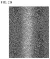
- Example 2B depicts an electromicroscopic photograph of an approach section in the die hole of the die of Comparative Example 1.
- the vertical direction of FIG. 2B is the axial direction.
- Example 1 Example 2
- Example 3 Ra1 0.0575 0.0884 0.0554 Ra2 0.1021 0.1382 0.1054 Ra3 0.0199 0.0508 0.0178 Life of die (amount of wire drawing (t)) 5.3 4.2 6.0
- Comparative Example 1 Comparative Example 2 Comparative Example 3 Comparative Example 4 Comparative Example 5
- Table 1 showed that Examples 1 to 3 having performed abrasive flow machining on the approach section of the die hole satisfied the relationship of 0.14 ⁇ m > Ra2 > Ra1 > Ra3.
Landscapes
- Engineering & Computer Science (AREA)
- Mechanical Engineering (AREA)
- Chemical & Material Sciences (AREA)
- Manufacturing & Machinery (AREA)
- Materials Engineering (AREA)
- Metallurgy (AREA)
- Organic Chemistry (AREA)
- Metal Extraction Processes (AREA)
Abstract
Description
- The present invention relates to a metal wire rod drawing die (hereinafter also referred to simply as "die") and a method for manufacturing the die, and in particular, to a metal wire rod drawing die that has a longer life than conventional dies and that can prevent damage to a metal wire rod surface and a method for manufacturing the die.
- For metal wire rod drawing dies, cemented carbide is commonly used that has high hardness and has excellent abrasion resistance and impact resistance. Cemented carbide is produced by sintering hard particles of tungsten carbide (WC), titanium carbide (TiC), or the like with a binder of an iron group metal such as cobalt (Co) or nickel (Ni). The most common cemented carbide is an alloy containing WC as hard particles and Co as a binder, and dies made of a cemented carbide that has the composition are used for metal wire rod drawing.
- A die is usually manufactured by undergoing a sizing step of polishing the inner surface of a prepared hole of a new die with the prepared hole formed therein or a used die as a primary material to form a die hole having a predetermined diameter. Today, polishing of the inner surface of a die hole is performed by inserting a polishing needle in the die hole while rotating the die and the polishing needle (e.g., Patent Document 1).
- Patent Document 1: Japanese Unexamined Patent Application Publication No.
H11-57843 - However, attempts to enhance the strength of a metal wire rod to be drawn and to perform high-speed wire drawing can cause problems such as early abrasion of a die. For example, high-speed wire drawing requires addressing problems that: (i) early abrasion of a die is serious, which shortens the life of the die; (ii) the surface of a drawn wire rod becomes rough and damage occurs; and (iii) after wire drawing, the amount of a lubrication component remaining on a wire rod surface is reduced, lowering lubricity in wire drawing. Boronizing for improving abrasion resistance is an option for deal with such problems. However, mere improvements in boronizing conditions and the like are not necessarily enough, and additional measures are needed.
- Accordingly, it is an object of the present invention to provide a metal wire rod drawing die that has a longer life than conventional dies and that can prevent damage to a metal wire rod surface and a method for manufacturing the die.
- The present inventor has conducted intensive and extensive studies and consequently found that the hole of a new die has a damage caused during the polishing process in a direction intersecting with an axial direction of the hole, and such a polishing damage causes the above problems. Thus, by setting the surface roughness Ra of the inner surface of the die hole as follows, the inventor has succeeded in reducing damage to a metal wire rod surface along with favorable extension of the life of the die, thereby completing the invention.
- Specifically, a metal wire rod drawing die of the present invention is a metal wire rod drawing die with a die hole formed therein for inserting a metal wire rod,
the die being characterized in that the die hole includes an approach section tapered in a direction in which the metal wire rod is inserted and a bearing section having a constant inner diameter located at a subsequent stage to the approach section; and where Ra1 represents a surface roughness of an inner surface of the die hole from the bearing section to the approach section corresponding to an area reduction rate of 30% in an axial direction of the die hole, Ra2 represents a surface roughness of the inner surface of the die hole from the bearing section to the approach section corresponding to the area reduction rate of 30% in a direction orthogonal to the axial direction of the die hole, and Ra3 represents a surface roughness of an inner surface of the bearing section of the die hole in the axial direction of the die hole, the Ra1, the Ra2, and the Ra3 satisfy a relationship represented by the following formula:
- A method for manufacturing a metal wire rod drawing die of the present invention is a method for manufacturing the metal wire rod drawing die of the invention described above,
the method being characterized by including a sizing step of polishing the inner surface of the die hole for inserting a metal wire rod to a predetermined diameter and a polishing step of polishing the inner surface of the die hole by abrasive flow machining after the sizing step. - According to the present invention, there is provided a metal wire rod drawing die that has a longer life than conventional dies and that can prevent damage to a metal wire rod surface and a method for manufacturing the die.
-
-
FIG. 1A is a perspective view of a die according to one suitable embodiment of the present invention, andFIG. 1B is a cross-sectional view of the die in a direction along line A-A ofFIG. 1A . -
FIG. 2A is an electrophotograph of an approach section in the die hole of a die of Example 1, andFIG. 2B is an electrophotograph of an approach section in the die hole of a die of Comparative Example 1. - Hereinafter, embodiments of the present invention will be described in detail by using the drawings.
-
FIG. 1A is a perspective view of a die according to one suitable embodiment of the invention, andFIG. 1B is a cross-sectional view of the die in a direction along line A-A ofFIG. 1A . In the illustrated example, adie 1 has a cylindrical outer shape, and substantially at a center thereof is provided adie hole 2 for inserting a metal wire rod. As depicted inFIG. 1B , thedie hole 2 includes anapproach section 2a formed to be tapered toward an exit direction for a wire rod to be drawn, abearing section 2b having a constant inner diameter located at a subsequent stage of theapproach section 2a, and arelease section 2c having an inner diameter enlarged toward the exit direction at a subsequent stage of thebearing section 2b. In theapproach section 2a is provided a predetermined tapered angle. A metal wire rod is fed in from anapproach section 2a side, and drawn toward thebearing section 2b. At this time, the diameter of the metal wire rod is drawn-squeezed by tapering of theapproach section 2a, thereby performing wire drawing. - In the metal wire rod drawing die of the invention, where Ra1 represents a surface roughness of an inner surface from the
bearing section 2b to theapproach section 2a corresponding to an area reduction rate of 30% in an axial direction of thedie hole 2, Ra2 represents a surface roughness of the inner surface of thedie hole 2 from thebearing section 2b to theapproach section 2a corresponding to the area reduction rate of 30% in a direction orthogonal to the axial direction, and Ra3 represents a surface roughness of an inner surface of thebearing section 2b of thedie hole 2 in the axial direction of thedie hole 2, the Ra1, the Ra2, and the Ra3 satisfy a relationship represented by the following formula:
- In
FIG. 1B , arrows of Ra1, Ra2, and Ra3 indicate directions of the respective surface roughnesses. - When the Ra2 is less than 0.14 µm, the inner surface of the
approach section 2a in the direction orthogonal to the axial direction of the hole is sufficiently smoothed. Thus, the flow resistance of a lubricant in the die hole is reduced, and the frictional resistance of the metal wire rod in the direction of wire drawing is reduced. Accordingly, damage to a metal wire rod surface can be reduced. Additionally, the reduced flow resistance of the lubricant reduces the frictional resistance of the metal wire rod. Due to that, early abrasion of the die is reduced, so that the life of the die can be improved. In addition, by making the Ra in the wire rod insertion direction of the metal wire rod, i.e., the Ra1 smaller than the Ra2, the frictional resistance of the metal wire rod can be further reduced. In addition, when the metal wire rod is inserted, the Ra3 of thebearing section 2b determines smoothness of the surface of the metal wire rod to be finished. Thus, the Ra of this section is made the smallest, i.e., Ra1 > Ra3. Particularly, the surface roughness Ra2 in the direction orthogonal to the axial direction of thedie hole 2 is suitably equal to or less than 0.11 µm. - The die 1 of the invention is required to have characteristics of being hard and hardly abrasive, and therefore is preferably made of a cemented carbide produced by sintering a powder of a hard carbide or nitride with a powder of a soft metal as a binder. Examples of hard carbides and nitrides include WC, VC, TiC, TaC, NbC, Cr3C2, Mo2C, VC, and TiN as unary systems, and WC-TiC, TiC-TiN, WC-TiC-TaC (NbC), and WC-TiC-TiN as pseudo-binary or pseudo-ternary systems. On the other hand, as the soft metal serving as the binder, besides Co, Ni, Co-Ni, Ni-Fe, or the like can be used. Preferred is a die that includes WC as hard particles and Co as the binder.
- The die 1 of the invention has no particular limitation other than to satisfy the relationship represented by 0.14 µm > Ra2 > Ra1 > Ra3. The die 1 of the invention is used for metal wire rod drawing. Examples of a metal wire rod to be drawn include a steel wire, a stainless steel wire, and a high carbon steel wire, and the surfaces of these wires may be those that have been subjected to a plating process or the like.
- Next will be described a method for manufacturing a metal wire rod drawing die of the invention.
- In general, a metal wire rod drawing die is manufactured by undergoing a sizing step of polishing a die hole of a new die with the die hole for inserting a metal wire rod formed therein or a die hole of a used die. The method for manufacturing a metal wire rod drawing die of the invention is a method for manufacturing the metal wire rod drawing die of the invention described above, and includes a sizing step of polishing the inner surface of the die hole for inserting a metal wire rod to a predetermined diameter and a polishing step of polishing the inner surface of the die hole by abrasive flow machining after the sizing step. Thereby, the flow resistance of a lubricant in the die hole is reduced and therefore the abrasion resistance of the metal wire rod in a wire drawing direction can be reduced, so that damage to a metal wire rod surface can be reduced. In addition, abrasion of the die is reduced, and thus the life of the die can also be improved.
- Abrasive flow machining is a surface polishing method using a viscoelastic fluid, which is referred to as polishing medium, prepared by mixing and kneading abrasive grains, and is a method of performing processing by causing the polishing medium to flow in a die hole and press-moving the abrasive grains in the polishing medium to the inner surface of the die hole. Thus, when abrasive flow machining is performed on the inner surface of the
die hole 2, polishing of thebearing section 2b is performed under higher polishing pressure, whereby the Ra3 becomes smaller than the Ra1. Additionally, since abrasive flow machining allows the polishing medium to reciprocate in the die hole under a predetermined pressure, the Ra1 becomes smaller than the Ra2. Accordingly, by performing abrasive flow machining on the inner surface of thedie hole 2 until the Ra2 becomes less than 0.14 µm, a metal wire rod drawing die can be obtained that satisfies the following formula:
- Additionally, in conventional polishing methods, the Ra2 can be made equal to or less than 0.14 µm by making small the particle diameter of diamond included in the polishing needle, but the relationship of Ra2 > Ra1 > Ra3 cannot be satisfied.
- As for the abrasive grains of the polishing medium used in the method for manufacturing the die of the invention, silicon carbide, aluminum oxide, diamond, or the like may be used. Additionally, abrasive grains having a particle diameter of, for example, about from 10 to 80 µm can be used, where a particle diameter according to the hole diameter of a die hole to be intended may be selected as appropriate. The shape of the abrasive grains is also not particularly limited, and examples thereof include spherical, indefinite, flat, and dish-like shapes. Preferred is a spherical shape. For example, in the method for manufacturing the die of the invention, a diamond powder having a particle diameter of about 30 µm can be suitably used as abrasive grains. In addition, the viscoelastic fluid of the polishing medium is not particularly limited, and any viscoelastic material conventionally used in abrasive flow machining can be used.
- For example, in polishing using, as abrasive grains, a diamond powder having a particle diameter of 30 µm at a polishing pressure of 90 ± 5 kgf/cm2 (about 8.8 MPa), a polishing time of about 80 seconds may be used for a die hole having a narrow diameter, such as less than 0.2 mm; about 40 seconds for a die hole diameter of about 0.5 mm, and about 20 seconds for a large die hole diameter, such as equal to or more than 0.9 mm. In addition, the polishing pressure is not limited to the above range. Under high polishing pressure, the polishing time can be shortened, whereas variation in polishing between individual dies to be polished may become large.
- The only important thing for the method for manufacturing the die of the invention is to include the sizing step of polishing the inner surface of a die hole for inserting a metal wire rod to a predetermined diameter and the polishing step of polishing the inner surface of the die hole by abrasive flow machining after the sizing step. There is no limitation other than that, and any well-known technique can be employed. For example, the polishing of the die hole in the sizing step may be performed by inserting a polishing needle in the die hole while rotating the die and the polishing needle, as in conventional techniques.
- In addition, by performing a boronizing process after the polishing step, that is, undergoing a so-called boronizing process step thereafter, the hardness of a die hole surface may be enhanced so that abrasion resistance is improved. Additionally, the boronizing process can be performed by any well-known method. For example, boronizing can be performed by mixing boron carbide (B4C) in liquid paraffin to make into a paste form, filling the obtained boron carbide-containing liquid paraffin into the die hole, and heating in an electric furnace or the like.
- Hereinafter, the present invention will be described in more detail by using Examples.
- As a sizing step, while rotating a die provided with a prepared hole and a polishing needle, a polishing needle was inserted into the die hole to polish respective die holes of three dies so that a machining margin in abrasive flow machining became about 3 µm. Next, as a polishing step, the die hole of each die polished by the polishing needle was polished using an abrasive flow machining device EX-800 model manufactured by Extrude Hone Co., Ltd. Each die obtained was cut into half along a longitudinal direction of the die, and the Ra1, the Ra2, and the Ra3 of the die hole after the abrasive flow machining were measured. In addition, using each die, wire drawing was performed on a metal wire rod to examine the life of each die. Table 1 depicts obtained results, and
FIG. 2A depicts an electromicroscopic photograph of an approach section in a hole of the die of Example 1. The vertical direction ofFIG. 2A is the axial direction. In addition, polishing of the die hole was performed by reciprocating an abrasion medium in the die hole at a pressure of 8.8 MPa (90 kgf/cm2). Details of the polishing medium are as follows: - Binder: silicone-based boride compound polymer
- Polishing agent: black silicon carbide
- Abrasive grains: diamond powder having a particle diameter of 30 µm
- Release agent: lubricant material containing a mineral oil and a lubricant
- While rotating a die provided with a prepared hole and a polishing needle, the polishing needle was inserted into the die hole to polish respective die holes of five dies so that a machining margin in abrasive flow machining became about 3 µm. In addition, in order to obtain a predetermined Ra distribution, the hardness and particle diameter of abrasive grains of the polishing needle were adjusted as appropriate. After that, without performing abrasive flow machining, obtained each die was cut into half along a longitudinal direction of the die, and the Ra1, the Ra2, and the Ra3 were measured. Additionally, using each die, wire drawing was performed on a metal wire rod to examine the life of the each die. Table 1 depicts obtained results. In addition,
FIG. 2B depicts an electromicroscopic photograph of an approach section in the die hole of the die of Comparative Example 1. The vertical direction ofFIG. 2B is the axial direction.[Table 1] Example 1 Example 2 Example 3 Ra1 0.0575 0.0884 0.0554 Ra2 0.1021 0.1382 0.1054 Ra3 0.0199 0.0508 0.0178 Life of die (amount of wire drawing (t)) 5.3 4.2 6.0 [Table 2] Comparative Example 1 Comparative Example 2 Comparative Example 3 Comparative Example 4 Comparative Example 5 Ra1 0.1460 0.1448 0.1460 0.1012 0.0223 Ra2 0.1432 0.1461 0.1482 0.0557 0.1011 Ra3 0.1084 0.1072 0.1084 0.0212 0.0621 Life of die (amount of wire drawing (t)) 0.4 0.5 0.4 3.1 3.7 - Table 1 showed that Examples 1 to 3 having performed abrasive flow machining on the approach section of the die hole satisfied the relationship of 0.14 µm > Ra2 > Ra1 > Ra3. On the other hand, Comparative Examples 1 to 5 having performed no abrasive flow machining on the approach section of the die hole all had a surface roughness Ra2 of equal to or more than 0.14 µm. In addition, it is shown that even in the amounts of metal wire rod drawing, the dies of Examples 1 to 3 are excellent as compared to the dies of Comparative Examples 1 to 5.
-
- 1
- Die
- 2
- Die hole
- 2a
- Approach section
- 2b
- Bearing section
- 2c
- Release section
Claims (2)
- A metal wire rod drawing die with a die hole formed therein for inserting a metal wire rod, the die being characterized in that the die hole comprises an approach section tapered in a direction in which the metal wire rod is inserted and a bearing section having a constant inner diameter located at a subsequent stage to the approach section; and where Ra1 represents a surface roughness of an inner surface of the die hole from the bearing section to the approach section corresponding to an area reduction rate of 30% in an axial direction of the die hole, Ra2 represents a surface roughness of the inner surface of the die hole from the bearing section to the approach section corresponding to the area reduction rate of 30% in a direction orthogonal to the axial direction of the die hole, and Ra3 represents a surface roughness of an inner surface of the bearing section of the die hole in the axial direction of the die hole, the Ra1, the Ra2, and the Ra3 satisfy a relationship represented by the following formula:

- A method for manufacturing the metal wire rod drawing die according to claim 1, the method being characterized by comprising a sizing step of polishing the inner surface of the die hole for inserting a metal wire rod to a predetermined diameter and a polishing step of polishing the inner surface of the die hole by abrasive flow machining after the sizing step.
Applications Claiming Priority (2)
| Application Number | Priority Date | Filing Date | Title |
|---|---|---|---|
| JP2014086707A JP6313105B2 (en) | 2014-04-18 | 2014-04-18 | Metal wire drawing die and method for manufacturing the same |
| PCT/JP2015/059253 WO2015159675A1 (en) | 2014-04-18 | 2015-03-25 | Die for drawing metal wire rod, and method for manufacturing same |
Publications (3)
| Publication Number | Publication Date |
|---|---|
| EP3132865A1 true EP3132865A1 (en) | 2017-02-22 |
| EP3132865A4 EP3132865A4 (en) | 2017-05-03 |
| EP3132865B1 EP3132865B1 (en) | 2018-08-15 |
Family
ID=54323886
Family Applications (1)
| Application Number | Title | Priority Date | Filing Date |
|---|---|---|---|
| EP15779255.7A Not-in-force EP3132865B1 (en) | 2014-04-18 | 2015-03-25 | Die for drawing metal wire rod, and method for manufacturing same |
Country Status (5)
| Country | Link |
|---|---|
| US (1) | US10478877B2 (en) |
| EP (1) | EP3132865B1 (en) |
| JP (1) | JP6313105B2 (en) |
| CN (1) | CN106232251B (en) |
| WO (1) | WO2015159675A1 (en) |
Families Citing this family (3)
| Publication number | Priority date | Publication date | Assignee | Title |
|---|---|---|---|---|
| CN109731936A (en) * | 2019-03-20 | 2019-05-10 | 河北华伦线缆有限公司 | Heat-resisting aluminium alloy and other aluminium alloy wires drawing moulds |
| US12318828B2 (en) | 2020-08-24 | 2025-06-03 | A.L.M.T. Corp. | Wire drawing die |
| CN114888107A (en) * | 2022-04-08 | 2022-08-12 | 宁波长振铜业有限公司 | Forming method of complex section bar |
Family Cites Families (18)
| Publication number | Priority date | Publication date | Assignee | Title |
|---|---|---|---|---|
| JPS5183053A (en) * | 1974-07-11 | 1976-07-21 | Matsushita Electric Industrial Co Ltd | Mangan aruminiumu tansokeigokinjishakuno seizoho |
| US4270373A (en) * | 1979-05-30 | 1981-06-02 | Motoshiro Hirato | Apparatus and process for the fluid lubrication drawing of composite metal wires |
| DE3903398A1 (en) * | 1989-02-02 | 1990-08-09 | Akad Wissenschaften Ddr | Drawing die and method for the use thereof |
| JPH02255213A (en) * | 1989-03-28 | 1990-10-16 | Sumitomo Metal Ind Ltd | Cold drawing die |
| JPH1157843A (en) * | 1997-08-26 | 1999-03-02 | Tokyo Seiko Co Ltd | Die for wire drawing and polishing method thereof |
| WO2002072291A1 (en) * | 2001-03-14 | 2002-09-19 | Ecoform Umformtechnik Gmbh | Pressure drawing tool for drawing round and non-round billet-shaped metallic stock that is to be shaped |
| JP2004316699A (en) * | 2003-04-11 | 2004-11-11 | Nsk Ltd | Linear motion guide bearing device |
| EP1785204B1 (en) * | 2004-08-31 | 2012-05-30 | Sumitomo Metal Industries, Ltd. | Die, method of manufacturing stepped metal tube, and stepped metal tube |
| CN1318156C (en) * | 2004-12-23 | 2007-05-30 | 彭彤 | Manufacturing method of diamond wire drawing mould |
| MX2009000680A (en) * | 2006-07-17 | 2009-04-02 | Sung Gi Choe | A die assembly and a method of making it. |
| KR101273137B1 (en) | 2007-01-19 | 2013-06-13 | 스미토모덴키고교가부시키가이샤 | Wire drawing die |
| JP2009022973A (en) * | 2007-07-19 | 2009-02-05 | Hitachi Cable Ltd | Manufacturing method and manufacturing apparatus for stepped deformed section copper strip |
| CN201076874Y (en) * | 2007-08-17 | 2008-06-25 | 株洲硬质合金集团有限公司 | Wire-drawing die |
| JP5649928B2 (en) * | 2010-11-25 | 2015-01-07 | オリンパス株式会社 | Optical element molding die, optical element molding method, and optical element molding die manufacturing method |
| JP2012187594A (en) * | 2011-03-09 | 2012-10-04 | Kanai Hiroaki | Wire drawing die |
| GB201213558D0 (en) * | 2012-07-31 | 2012-09-12 | Univ Birmingham | Reconfigurable antenna |
| CN202877261U (en) * | 2012-09-29 | 2013-04-17 | 天津市永昌焊丝有限公司 | Die for drawing flux-cored wires |
| CN202845479U (en) * | 2012-11-08 | 2013-04-03 | 株洲长江硬质合金工具有限公司 | Steel pipe drawing die |
-
2014
- 2014-04-18 JP JP2014086707A patent/JP6313105B2/en not_active Expired - Fee Related
-
2015
- 2015-03-25 WO PCT/JP2015/059253 patent/WO2015159675A1/en not_active Ceased
- 2015-03-25 EP EP15779255.7A patent/EP3132865B1/en not_active Not-in-force
- 2015-03-25 CN CN201580020420.9A patent/CN106232251B/en not_active Expired - Fee Related
- 2015-03-25 US US15/304,608 patent/US10478877B2/en active Active
Also Published As
| Publication number | Publication date |
|---|---|
| US20170056946A1 (en) | 2017-03-02 |
| JP6313105B2 (en) | 2018-04-18 |
| CN106232251B (en) | 2018-04-24 |
| CN106232251A (en) | 2016-12-14 |
| JP2015205300A (en) | 2015-11-19 |
| EP3132865B1 (en) | 2018-08-15 |
| EP3132865A4 (en) | 2017-05-03 |
| US10478877B2 (en) | 2019-11-19 |
| WO2015159675A1 (en) | 2015-10-22 |
Similar Documents
| Publication | Publication Date | Title |
|---|---|---|
| JP2010514933A (en) | Corrosion resistant tool for cold forming | |
| EP3162779B1 (en) | Sintered object of cubic boron nitride and cutting tool | |
| EP3132865B1 (en) | Die for drawing metal wire rod, and method for manufacturing same | |
| US5235879A (en) | Tool of cemented carbide for cutting, punching or nibbling | |
| EP1741507B1 (en) | Twist drill | |
| CN101208166A (en) | Cermet inserts and cutting tools | |
| KR20180079356A (en) | Abrasion tool | |
| EP3393705A1 (en) | Cutting-tool main body | |
| JP6489505B2 (en) | Diamond coated cemented carbide cutting tool with improved cutting edge strength | |
| JP4313587B2 (en) | Cemented carbide and coated cemented carbide members and methods for producing them | |
| JP4974980B2 (en) | TiCN-based cermet | |
| JP5127110B2 (en) | TiCN-based cermet and method for producing the same | |
| JP7120524B2 (en) | Diamond bonded body and method for manufacturing diamond bonded body | |
| WO2008111894A1 (en) | A method of making a cemented carbide body | |
| JP5532413B2 (en) | Titanium carbonitride-based cermet cutting insert and method for producing the same | |
| JP2020132935A (en) | WC-based cemented carbide cutting tool with excellent fracture resistance and surface-coated WC-based cemented carbide cutting tool | |
| JP6380016B2 (en) | Cermet tools and coated cermet tools | |
| WO2000033994A1 (en) | Elongate support member and method of making the same | |
| EP1630242B1 (en) | Cemented carbide, coated cemented carbide member and production processes of the same | |
| JP6344807B2 (en) | Cutting edge-exchangeable cutting tips and processed products of cemented carbide using high-precision cemented carbide with fine free carbon dispersion | |
| EP4306671A1 (en) | Rock drill insert | |
| JP2019171627A (en) | Manufacturing method of honeycomb structure forming die, honeycomb structure forming die, and manufacturing method of honeycomb structure | |
| JP2008156756A (en) | TiCN-based cermet | |
| JP2001335877A (en) | Plug for manufacturing heat transfer tubes with internal grooves | |
| JP2023134936A (en) | Cemented carbide for cutting tools and cutting tool substrates using the alloy |
Legal Events
| Date | Code | Title | Description |
|---|---|---|---|
| STAA | Information on the status of an ep patent application or granted ep patent |
Free format text: STATUS: THE INTERNATIONAL PUBLICATION HAS BEEN MADE |
|
| PUAI | Public reference made under article 153(3) epc to a published international application that has entered the european phase |
Free format text: ORIGINAL CODE: 0009012 |
|
| STAA | Information on the status of an ep patent application or granted ep patent |
Free format text: STATUS: REQUEST FOR EXAMINATION WAS MADE |
|
| 17P | Request for examination filed |
Effective date: 20161116 |
|
| AK | Designated contracting states |
Kind code of ref document: A1 Designated state(s): AL AT BE BG CH CY CZ DE DK EE ES FI FR GB GR HR HU IE IS IT LI LT LU LV MC MK MT NL NO PL PT RO RS SE SI SK SM TR |
|
| AX | Request for extension of the european patent |
Extension state: BA ME |
|
| RIC1 | Information provided on ipc code assigned before grant |
Ipc: B21C 3/02 20060101AFI20170322BHEP |
|
| A4 | Supplementary search report drawn up and despatched |
Effective date: 20170403 |
|
| RIC1 | Information provided on ipc code assigned before grant |
Ipc: B21C 3/02 20060101AFI20170328BHEP |
|
| DAV | Request for validation of the european patent (deleted) | ||
| DAX | Request for extension of the european patent (deleted) | ||
| GRAP | Despatch of communication of intention to grant a patent |
Free format text: ORIGINAL CODE: EPIDOSNIGR1 |
|
| STAA | Information on the status of an ep patent application or granted ep patent |
Free format text: STATUS: GRANT OF PATENT IS INTENDED |
|
| INTG | Intention to grant announced |
Effective date: 20180308 |
|
| GRAS | Grant fee paid |
Free format text: ORIGINAL CODE: EPIDOSNIGR3 |
|
| GRAA | (expected) grant |
Free format text: ORIGINAL CODE: 0009210 |
|
| STAA | Information on the status of an ep patent application or granted ep patent |
Free format text: STATUS: THE PATENT HAS BEEN GRANTED |
|
| AK | Designated contracting states |
Kind code of ref document: B1 Designated state(s): AL AT BE BG CH CY CZ DE DK EE ES FI FR GB GR HR HU IE IS IT LI LT LU LV MC MK MT NL NO PL PT RO RS SE SI SK SM TR |
|
| REG | Reference to a national code |
Ref country code: CH Ref legal event code: EP Ref country code: GB Ref legal event code: FG4D Ref country code: AT Ref legal event code: REF Ref document number: 1029165 Country of ref document: AT Kind code of ref document: T Effective date: 20180815 |
|
| REG | Reference to a national code |
Ref country code: IE Ref legal event code: FG4D |
|
| REG | Reference to a national code |
Ref country code: DE Ref legal event code: R096 Ref document number: 602015014908 Country of ref document: DE |
|
| REG | Reference to a national code |
Ref country code: NL Ref legal event code: MP Effective date: 20180815 |
|
| REG | Reference to a national code |
Ref country code: LT Ref legal event code: MG4D |
|
| REG | Reference to a national code |
Ref country code: AT Ref legal event code: MK05 Ref document number: 1029165 Country of ref document: AT Kind code of ref document: T Effective date: 20180815 |
|
| PG25 | Lapsed in a contracting state [announced via postgrant information from national office to epo] |
Ref country code: BG Free format text: LAPSE BECAUSE OF FAILURE TO SUBMIT A TRANSLATION OF THE DESCRIPTION OR TO PAY THE FEE WITHIN THE PRESCRIBED TIME-LIMIT Effective date: 20181115 Ref country code: GR Free format text: LAPSE BECAUSE OF FAILURE TO SUBMIT A TRANSLATION OF THE DESCRIPTION OR TO PAY THE FEE WITHIN THE PRESCRIBED TIME-LIMIT Effective date: 20181116 Ref country code: AT Free format text: LAPSE BECAUSE OF FAILURE TO SUBMIT A TRANSLATION OF THE DESCRIPTION OR TO PAY THE FEE WITHIN THE PRESCRIBED TIME-LIMIT Effective date: 20180815 Ref country code: NL Free format text: LAPSE BECAUSE OF FAILURE TO SUBMIT A TRANSLATION OF THE DESCRIPTION OR TO PAY THE FEE WITHIN THE PRESCRIBED TIME-LIMIT Effective date: 20180815 Ref country code: SE Free format text: LAPSE BECAUSE OF FAILURE TO SUBMIT A TRANSLATION OF THE DESCRIPTION OR TO PAY THE FEE WITHIN THE PRESCRIBED TIME-LIMIT Effective date: 20180815 Ref country code: IS Free format text: LAPSE BECAUSE OF FAILURE TO SUBMIT A TRANSLATION OF THE DESCRIPTION OR TO PAY THE FEE WITHIN THE PRESCRIBED TIME-LIMIT Effective date: 20181215 Ref country code: RS Free format text: LAPSE BECAUSE OF FAILURE TO SUBMIT A TRANSLATION OF THE DESCRIPTION OR TO PAY THE FEE WITHIN THE PRESCRIBED TIME-LIMIT Effective date: 20180815 Ref country code: NO Free format text: LAPSE BECAUSE OF FAILURE TO SUBMIT A TRANSLATION OF THE DESCRIPTION OR TO PAY THE FEE WITHIN THE PRESCRIBED TIME-LIMIT Effective date: 20181115 Ref country code: FI Free format text: LAPSE BECAUSE OF FAILURE TO SUBMIT A TRANSLATION OF THE DESCRIPTION OR TO PAY THE FEE WITHIN THE PRESCRIBED TIME-LIMIT Effective date: 20180815 Ref country code: LT Free format text: LAPSE BECAUSE OF FAILURE TO SUBMIT A TRANSLATION OF THE DESCRIPTION OR TO PAY THE FEE WITHIN THE PRESCRIBED TIME-LIMIT Effective date: 20180815 |
|
| PG25 | Lapsed in a contracting state [announced via postgrant information from national office to epo] |
Ref country code: LV Free format text: LAPSE BECAUSE OF FAILURE TO SUBMIT A TRANSLATION OF THE DESCRIPTION OR TO PAY THE FEE WITHIN THE PRESCRIBED TIME-LIMIT Effective date: 20180815 Ref country code: HR Free format text: LAPSE BECAUSE OF FAILURE TO SUBMIT A TRANSLATION OF THE DESCRIPTION OR TO PAY THE FEE WITHIN THE PRESCRIBED TIME-LIMIT Effective date: 20180815 Ref country code: AL Free format text: LAPSE BECAUSE OF FAILURE TO SUBMIT A TRANSLATION OF THE DESCRIPTION OR TO PAY THE FEE WITHIN THE PRESCRIBED TIME-LIMIT Effective date: 20180815 |
|
| PG25 | Lapsed in a contracting state [announced via postgrant information from national office to epo] |
Ref country code: RO Free format text: LAPSE BECAUSE OF FAILURE TO SUBMIT A TRANSLATION OF THE DESCRIPTION OR TO PAY THE FEE WITHIN THE PRESCRIBED TIME-LIMIT Effective date: 20180815 Ref country code: CZ Free format text: LAPSE BECAUSE OF FAILURE TO SUBMIT A TRANSLATION OF THE DESCRIPTION OR TO PAY THE FEE WITHIN THE PRESCRIBED TIME-LIMIT Effective date: 20180815 Ref country code: PL Free format text: LAPSE BECAUSE OF FAILURE TO SUBMIT A TRANSLATION OF THE DESCRIPTION OR TO PAY THE FEE WITHIN THE PRESCRIBED TIME-LIMIT Effective date: 20180815 Ref country code: ES Free format text: LAPSE BECAUSE OF FAILURE TO SUBMIT A TRANSLATION OF THE DESCRIPTION OR TO PAY THE FEE WITHIN THE PRESCRIBED TIME-LIMIT Effective date: 20180815 Ref country code: IT Free format text: LAPSE BECAUSE OF FAILURE TO SUBMIT A TRANSLATION OF THE DESCRIPTION OR TO PAY THE FEE WITHIN THE PRESCRIBED TIME-LIMIT Effective date: 20180815 Ref country code: EE Free format text: LAPSE BECAUSE OF FAILURE TO SUBMIT A TRANSLATION OF THE DESCRIPTION OR TO PAY THE FEE WITHIN THE PRESCRIBED TIME-LIMIT Effective date: 20180815 |
|
| REG | Reference to a national code |
Ref country code: DE Ref legal event code: R097 Ref document number: 602015014908 Country of ref document: DE |
|
| PG25 | Lapsed in a contracting state [announced via postgrant information from national office to epo] |
Ref country code: SK Free format text: LAPSE BECAUSE OF FAILURE TO SUBMIT A TRANSLATION OF THE DESCRIPTION OR TO PAY THE FEE WITHIN THE PRESCRIBED TIME-LIMIT Effective date: 20180815 Ref country code: SM Free format text: LAPSE BECAUSE OF FAILURE TO SUBMIT A TRANSLATION OF THE DESCRIPTION OR TO PAY THE FEE WITHIN THE PRESCRIBED TIME-LIMIT Effective date: 20180815 Ref country code: DK Free format text: LAPSE BECAUSE OF FAILURE TO SUBMIT A TRANSLATION OF THE DESCRIPTION OR TO PAY THE FEE WITHIN THE PRESCRIBED TIME-LIMIT Effective date: 20180815 |
|
| PLBE | No opposition filed within time limit |
Free format text: ORIGINAL CODE: 0009261 |
|
| STAA | Information on the status of an ep patent application or granted ep patent |
Free format text: STATUS: NO OPPOSITION FILED WITHIN TIME LIMIT |
|
| 26N | No opposition filed |
Effective date: 20190516 |
|
| PG25 | Lapsed in a contracting state [announced via postgrant information from national office to epo] |
Ref country code: SI Free format text: LAPSE BECAUSE OF FAILURE TO SUBMIT A TRANSLATION OF THE DESCRIPTION OR TO PAY THE FEE WITHIN THE PRESCRIBED TIME-LIMIT Effective date: 20180815 |
|
| PG25 | Lapsed in a contracting state [announced via postgrant information from national office to epo] |
Ref country code: MC Free format text: LAPSE BECAUSE OF FAILURE TO SUBMIT A TRANSLATION OF THE DESCRIPTION OR TO PAY THE FEE WITHIN THE PRESCRIBED TIME-LIMIT Effective date: 20180815 |
|
| REG | Reference to a national code |
Ref country code: CH Ref legal event code: PL |
|
| GBPC | Gb: european patent ceased through non-payment of renewal fee |
Effective date: 20190325 |
|
| PG25 | Lapsed in a contracting state [announced via postgrant information from national office to epo] |
Ref country code: LU Free format text: LAPSE BECAUSE OF NON-PAYMENT OF DUE FEES Effective date: 20190325 |
|
| REG | Reference to a national code |
Ref country code: BE Ref legal event code: MM Effective date: 20190331 |
|
| PG25 | Lapsed in a contracting state [announced via postgrant information from national office to epo] |
Ref country code: LI Free format text: LAPSE BECAUSE OF NON-PAYMENT OF DUE FEES Effective date: 20190331 Ref country code: CH Free format text: LAPSE BECAUSE OF NON-PAYMENT OF DUE FEES Effective date: 20190331 Ref country code: IE Free format text: LAPSE BECAUSE OF NON-PAYMENT OF DUE FEES Effective date: 20190325 Ref country code: GB Free format text: LAPSE BECAUSE OF NON-PAYMENT OF DUE FEES Effective date: 20190325 |
|
| PG25 | Lapsed in a contracting state [announced via postgrant information from national office to epo] |
Ref country code: BE Free format text: LAPSE BECAUSE OF NON-PAYMENT OF DUE FEES Effective date: 20190331 |
|
| PG25 | Lapsed in a contracting state [announced via postgrant information from national office to epo] |
Ref country code: TR Free format text: LAPSE BECAUSE OF FAILURE TO SUBMIT A TRANSLATION OF THE DESCRIPTION OR TO PAY THE FEE WITHIN THE PRESCRIBED TIME-LIMIT Effective date: 20180815 |
|
| PG25 | Lapsed in a contracting state [announced via postgrant information from national office to epo] |
Ref country code: MT Free format text: LAPSE BECAUSE OF NON-PAYMENT OF DUE FEES Effective date: 20190325 Ref country code: PT Free format text: LAPSE BECAUSE OF FAILURE TO SUBMIT A TRANSLATION OF THE DESCRIPTION OR TO PAY THE FEE WITHIN THE PRESCRIBED TIME-LIMIT Effective date: 20181215 |
|
| PG25 | Lapsed in a contracting state [announced via postgrant information from national office to epo] |
Ref country code: CY Free format text: LAPSE BECAUSE OF FAILURE TO SUBMIT A TRANSLATION OF THE DESCRIPTION OR TO PAY THE FEE WITHIN THE PRESCRIBED TIME-LIMIT Effective date: 20180815 |
|
| PG25 | Lapsed in a contracting state [announced via postgrant information from national office to epo] |
Ref country code: HU Free format text: LAPSE BECAUSE OF FAILURE TO SUBMIT A TRANSLATION OF THE DESCRIPTION OR TO PAY THE FEE WITHIN THE PRESCRIBED TIME-LIMIT; INVALID AB INITIO Effective date: 20150325 |
|
| PGFP | Annual fee paid to national office [announced via postgrant information from national office to epo] |
Ref country code: DE Payment date: 20220322 Year of fee payment: 8 |
|
| PGFP | Annual fee paid to national office [announced via postgrant information from national office to epo] |
Ref country code: FR Payment date: 20220322 Year of fee payment: 8 |
|
| PG25 | Lapsed in a contracting state [announced via postgrant information from national office to epo] |
Ref country code: MK Free format text: LAPSE BECAUSE OF FAILURE TO SUBMIT A TRANSLATION OF THE DESCRIPTION OR TO PAY THE FEE WITHIN THE PRESCRIBED TIME-LIMIT Effective date: 20180815 |
|
| REG | Reference to a national code |
Ref country code: DE Ref legal event code: R119 Ref document number: 602015014908 Country of ref document: DE |
|
| PG25 | Lapsed in a contracting state [announced via postgrant information from national office to epo] |
Ref country code: FR Free format text: LAPSE BECAUSE OF NON-PAYMENT OF DUE FEES Effective date: 20230331 Ref country code: DE Free format text: LAPSE BECAUSE OF NON-PAYMENT OF DUE FEES Effective date: 20231003 |