EP3132558B1 - System for transmission and/or reception of signals having electromagnetic modes with orbital angular momentum, and device and method thereof - Google Patents
System for transmission and/or reception of signals having electromagnetic modes with orbital angular momentum, and device and method thereof Download PDFInfo
- Publication number
- EP3132558B1 EP3132558B1 EP15724054.0A EP15724054A EP3132558B1 EP 3132558 B1 EP3132558 B1 EP 3132558B1 EP 15724054 A EP15724054 A EP 15724054A EP 3132558 B1 EP3132558 B1 EP 3132558B1
- Authority
- EP
- European Patent Office
- Prior art keywords
- signals
- radio
- input
- output
- fourier transform
- Prior art date
- Legal status (The legal status is an assumption and is not a legal conclusion. Google has not performed a legal analysis and makes no representation as to the accuracy of the status listed.)
- Active
Links
Images


Classifications
-
- H—ELECTRICITY
- H01—ELECTRIC ELEMENTS
- H01Q—ANTENNAS, i.e. RADIO AERIALS
- H01Q21/00—Antenna arrays or systems
- H01Q21/06—Arrays of individually energised antenna units similarly polarised and spaced apart
- H01Q21/20—Arrays of individually energised antenna units similarly polarised and spaced apart the units being spaced along or adjacent to a curvilinear path
- H01Q21/205—Arrays of individually energised antenna units similarly polarised and spaced apart the units being spaced along or adjacent to a curvilinear path providing an omnidirectional coverage
-
- H—ELECTRICITY
- H04—ELECTRIC COMMUNICATION TECHNIQUE
- H04L—TRANSMISSION OF DIGITAL INFORMATION, e.g. TELEGRAPHIC COMMUNICATION
- H04L5/00—Arrangements affording multiple use of the transmission path
- H04L5/02—Channels characterised by the type of signal
- H04L5/04—Channels characterised by the type of signal the signals being represented by different amplitudes or polarities, e.g. quadriplex
-
- H—ELECTRICITY
- H01—ELECTRIC ELEMENTS
- H01Q—ANTENNAS, i.e. RADIO AERIALS
- H01Q3/00—Arrangements for changing or varying the orientation or the shape of the directional pattern of the waves radiated from an antenna or antenna system
- H01Q3/26—Arrangements for changing or varying the orientation or the shape of the directional pattern of the waves radiated from an antenna or antenna system varying the relative phase or relative amplitude of energisation between two or more active radiating elements; varying the distribution of energy across a radiating aperture
- H01Q3/30—Arrangements for changing or varying the orientation or the shape of the directional pattern of the waves radiated from an antenna or antenna system varying the relative phase or relative amplitude of energisation between two or more active radiating elements; varying the distribution of energy across a radiating aperture varying the relative phase between the radiating elements of an array
- H01Q3/34—Arrangements for changing or varying the orientation or the shape of the directional pattern of the waves radiated from an antenna or antenna system varying the relative phase or relative amplitude of energisation between two or more active radiating elements; varying the distribution of energy across a radiating aperture varying the relative phase between the radiating elements of an array by electrical means
- H01Q3/40—Arrangements for changing or varying the orientation or the shape of the directional pattern of the waves radiated from an antenna or antenna system varying the relative phase or relative amplitude of energisation between two or more active radiating elements; varying the distribution of energy across a radiating aperture varying the relative phase between the radiating elements of an array by electrical means with phasing matrix
-
- H—ELECTRICITY
- H04—ELECTRIC COMMUNICATION TECHNIQUE
- H04B—TRANSMISSION
- H04B7/00—Radio transmission systems, i.e. using radiation field
- H04B7/02—Diversity systems; Multi-antenna system, i.e. transmission or reception using multiple antennas
- H04B7/10—Polarisation diversity; Directional diversity
-
- H—ELECTRICITY
- H01—ELECTRIC ELEMENTS
- H01Q—ANTENNAS, i.e. RADIO AERIALS
- H01Q1/00—Details of, or arrangements associated with, antennas
- H01Q1/12—Supports; Mounting means
- H01Q1/22—Supports; Mounting means by structural association with other equipment or articles
- H01Q1/24—Supports; Mounting means by structural association with other equipment or articles with receiving set
- H01Q1/241—Supports; Mounting means by structural association with other equipment or articles with receiving set used in mobile communications, e.g. GSM
- H01Q1/246—Supports; Mounting means by structural association with other equipment or articles with receiving set used in mobile communications, e.g. GSM specially adapted for base stations
-
- H—ELECTRICITY
- H01—ELECTRIC ELEMENTS
- H01Q—ANTENNAS, i.e. RADIO AERIALS
- H01Q21/00—Antenna arrays or systems
- H01Q21/06—Arrays of individually energised antenna units similarly polarised and spaced apart
-
- H—ELECTRICITY
- H01—ELECTRIC ELEMENTS
- H01Q—ANTENNAS, i.e. RADIO AERIALS
- H01Q21/00—Antenna arrays or systems
- H01Q21/06—Arrays of individually energised antenna units similarly polarised and spaced apart
- H01Q21/20—Arrays of individually energised antenna units similarly polarised and spaced apart the units being spaced along or adjacent to a curvilinear path
Definitions
- the present invention relates to a system, and related device and method, for communication of signals having electromagnetic modes with orbital angular momentum, or OAM
- the electromagnetic orbital angular momentum is an extrinsic property of the electromagnetic field and of every single photon, and describes the orbital characteristics of its rotational degrees of freedom.
- the electromagnetic field phase factor exp ⁇ iacp ⁇ is associated with OAM, where ⁇ is the azimuthal angle around the axis of the wave beam and ⁇ is the phase function, which may take any value.
- a wave beam carrying an arbitrary quantity of OAM modes contains a spectrum of discrete integer OAM self-modes which are mutually orthogonal, and hence will propagate independently.
- the signals are transmitted by using different orthogonal states of the orbital angular momentum, providing a virtually infinite number of channels that utilize the same carrier frequency, resulting in increased transmission rate.
- OAM can significantly increase the spectral capacity and efficiency of optical communication systems by encoding the information as orthogonal states and providing a virtually infinite number of channels using the same carrier frequency, or using different OAM states for multiplexing.
- a concentric and uniform circular antenna array was used.
- the antenna elements in the UCA were fed with the same input signal, but a phase delay was applied to each element, so that, after a full revolution, the phase would be incremented by an integer multiple k of 2 ⁇ .
- the field intensity diagrams calculated in the near field region were very similar to those obtained in paraxial optics. This study also underlined how the different OAM states in one beam can be decomposed by integrating the complex field vector weighted with exp(-jk ⁇ ) along a circle around the beam axis.
- OAM-based radio transmission provides one possible scheme for transmission at the same carrier frequency within the same band.
- OAM-based radio systems are disclosed by patent WO2012084039 and by the scientific publications XP055108309 of B. Thidé et al. "Utilization of photon orbital angular momentum in the low-frequency radio domain " and XP011403555 of O. Edfors et al. "Is Orbital Angular Momentum (OAM) Based Radio Communication an Unexploited Area? ".
- the following will describe a system, a device and a method for transmission and/or reception of signals having electromagnetic modes with orbital angular momentum, wherein the OAM signal generation process takes place through a device, i.e. a modal transformer, which applies a Fast Fourier transform (FFT).
- FFT Fast Fourier transform
- the modal transformer applies a Discrete Fourier Transform (DFT).
- DFT Discrete Fourier Transform
- the DFT is implemented through analog components, such as combiners/dividers and phase shifters, which can also be used with high-frequency passband signals.
- the OAM signals are generated during transmission.
- a similar device In reception, a similar device according to the invention allows the application of an inverse modal transformation, through the inverse Fast Fourier transform, to the received OAM signals, thereby obtaining as a result the originally transmitted electromagnetic signals.
- the system (1) for communication of signals having electromagnetic modes with orbital angular momentum (OAM) comprises a system 1T for generation and transmission of said OAM signals and a system 1R for reception of said OAM signals.
- OAM orbital angular momentum
- the system 1 provides for multiplexing M transmission channels L 0 ,L 1 ,...,L M-1 (block 3), each one having a bandwidth B, on a single radio channel having a bandwidth C, by using an array of N transmitting antennas 5 and N receiving antennas 6.
- the communication system 1 can be modelled as a block 7 with M inputs and M outputs. Up to M transmitters BBTx 0 ..BBTx M-1 (block 3), each one operating with a known modulation, are connected to said M inputs; the same number M of receivers BBRx 0 ..BBRx M-1 are connected to said M outputs (block 9).
- a receiver BBRx0 receives a signal coming from a transmitter BBTx0
- a receiver BBRx1 receives a signal coming from a transmitter BBTx1, and so on.
- the block 7 comprises a radio channel and antennas that might suffer from imperfections and parasitic couplings, the transfer matrix of said block 7 will not be ideal, i.e.
- Prior-art MIMO techniques can be used in order to diagonalize the transfer matrix and cancel mutual interferences.
- "XPIC” Cross Polar Interference Canceller
- the XPIC canceller estimates the component of the vertical polarization signal that interferes with the horizontal polarization signal, and subtracts it from the latter; the same is done for the other stream.
- the N transmitting antennas 5 are arranged equally spaced on a circumference. Such a type of antenna array allows the generation of OAM modes with angular index A, where -N/2 ⁇ A ⁇ N/2.
- the electromagnetic signals generated by the M baseband transmitters BBTx 0 ..BBTx M-1 are sent to the M inputs L 0 ,L 1 ,...,L M-1 , each one of which is allocated to a respective OAM mode.
- a device 11 i.e. a modal transformer TM 11 that performs a Fast Fourier transform (FFT).
- FFT Fast Fourier transform
- a Discrete Fourier Transform (DFT) will also be described as an alternative to the FFT. For example, let us consider as an input signal a unitary signal at the input with index h (where 0 ⁇ h ⁇ M) of the modal transformer TM 11; it will be transformed by the DFT into a phase ramp of the exp(j2 ⁇ hk/N) type at the outputs (k being the index of the DFT output).
- N is an integer power of two: this allows implementing an FFT (“Fast Fourier Transform”) algorithm, which is more efficient than the DFT.
- the main FFT algorithms referred to as “time decimation” and “frequency decimation” algorithms, utilize naturally arranged inputs and provide outputs with a “bit-reversal” arrangement (bit-reversal permutation), or vice versa: in cases of "bit-reversal" arrangement, the communication system 1 comprises a stream permutation block for obtaining again the natural arrangement.
- the frequency converter 13 (which is synchronous for all signals) allows obtaining output OAM signals at the frequency of the radio channel in use, i.e. it will convert the OAM signals from baseband into passband.
- the frequency-converted OAM signals are sent to the N transmitting antennas 5 (AT 0 ,AT 1 ,...,AT N-1 ).
- Such transmitting antennas 5 can be implemented by using any technology, e.g. dipoles, Yagi-Uda, horn, and so on.
- the directivity of the single antenna AT can be profitably exploited in order to improve the performance of the connection.
- an array of receiving antennas 6 (AR 0 ,AR 1 ,...,AR N-1 ) can be used, which is analogous and symmetrical to the transmitting one 5.
- a device 15 Downstream of the receiving antennas 6 there is a device 15 which is similar to the device 11 according to the invention; however, in this case it is an inverse modal transformer TMI 15, which implements the inverse FFT operation (IFFT), thereby selectively returning, at its outputs L 0 ,L 1 ,...,L M-1 , the electromagnetic signals that were transmitted on each OAM mode. Due to the linearity property of the modal transformer TM 11 and of the inverse modal transformer TMI 15, the system 1 can operate on multiple modes simultaneously.
- IFFT inverse FFT operation
- the same device 11,15 can be used both in transmission and in reception.
- the second DNC frequency converter 17 (Down-Converter), which is synchronous for all streams, with input at the frequency of the radio channel in use. Said DNC converter 17 allows bringing the received electromagnetic signals back into baseband.
- the second DNC frequency converter 17 preferably comprises a plurality (M) of frequency converters.
- an interference canceller XIC 19 which cancels any mutual interference of the signals in transit therein, i.e. it removes from each signal associated with a certain OAM mode the signals associated with other OAM modes.
- the interference canceller XIC 19 performs a function which is similar to the "Cross-Polar Interference Cancellation" technique.
- the modal transformer TM 11 and the inverse modal transformer TMI 15 operate on complex baseband signals, typically sampled ones.
- the architecture of the system 1 can therefore be easily integrated into transmitters and/or receivers created with sampled-data numeric processing techniques.
- the positions of the modal transformer TM 11 and of the first UPC frequency converter 13 are reversed, and the same applies in reception to the second DNC frequency converter 17 and the inverse modal transformer TMI 15.
- the modal transformer TM 11 and the inverse modal transformer TMI 15 will operate at the frequency of the selected radio channel, hence with passband signals.
- Said receiver Rx 21 can be connected to the inverse modal transformer TMI 15 through a selector 23 allowing selection of the signal coming from the desired h-th OAM mode.
- the receiver Rx 21 may therefore be any known receiving apparatus, e.g. a conventional radio-television receiver.
- the receiving antennas 6 are advantageously independent of the technology of the receiver Rx 21 and of the type of modulation in use.
- the first UPC frequency converter 13 can be eliminated, should it not be necessary to use all the transmitters Tx0..TxM-1.
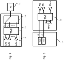
- Fig. 3 represents the case wherein only two transmitters, Tx0 and Tx1 (block 3) are directly connected to the modal transformer TM 11, and wherein each transmitter Tx0 and Tx1 comprises its own frequency converter ("Up Converter").
- the present invention also relates to a device 11 for generating OAM signals, i.e. the modal transformer TM 11 and the inverse modal transformer TMI 15.
- Both the modal transformer TM 11 and the inverse modal transformer TMI 15 comprise analog components (stages) arranged in cascade. Synthesis of such stages is obtained by using the sampled baseband data FFT processing methodology. However, in the present invention the synthesis technique is applied within a very different frame, i.e. to analog or anyway passband radio frequency circuits, as opposed to baseband digital signals, and to continuous signals as opposed to sampled signals. Moreover, the FFT is traditionally executed either en bloc or by discrete steps, since digital processors are used. In the present invention, instead, analog signals flow in a continuous stream through the circuits that apply the transform.
- the present invention preferably implements this property in passband, thereby attaining the useful result that the modal transformer TM 11 and the inverse modal transformer TMI 15 comprise radio frequency combiners/dividers and phase shifters.
- This provides a large bandwidth for the modal transformer TM 11 and the inverse modal transformer TMI 15, which will only be limited by the performance of the analog RF components employed. For example, a millimeter wave application may ensure bandwidths of tens of gigahertz, which could not be attained in real time with digital circuits.
- phase terms are defined as follows:
- the index N is the aforementioned number of inputs of the FFT; r is the exponent to which the basic complex exponential W N is raised in classic "time decimation” and “frequency decimation” FFT algorithms.
- the flow graph of Fig. 4 is implemented with radio frequency analog components 25,26,27,31.
- the radio frequency analog components 25,26,27,31 comprise first nodes 25, from which two branches extend, which are implemented as radio frequency signal dividers 25, and second nodes 26,27, into which two branches are added, which are implemented as radio frequency signal combiners (subtractors 27 or adders 26).
- the coefficient -1 (reference 29 in Fig. 4 ) can be implemented, in fact, as a divider 25 having an output with a 180° phase, or as the input of a combiner 26,27 having an input with a 180° phase.
- the analog radio frequency components 25,26,27,31 comprise, therefore, also the phase shifter 31.
- the phase shifter 31 is preferably implemented through a delay line, or is obtained by using an output of a divider 25 configured for obtaining a 90° phase, plus a 180° phase inversion or, respectively, by using the input of a combiner 26,27 configured for obtaining a 90° phase, plus a 180° phase inversion.
- Reordering of the output signals having values XO,X2,X1,X3 is attained by connecting the cables of the N transmitting antennas 5 in numerical order, as opposed to the positional order.
- a combiner/divider component 33 is introduced, which simultaneously provides the sum (S) and the difference (J) of the signals at the inputs 1 and 2. In this manner, one of these components 33 will replace two dividers 25 and two combiners 26,27 of the circuit of Fig. 5 ; therefore, four combiner/divider components 33 will replace sixteen of them.
- High-frequency dividers 25, combiners 26,27, phase shifters 31 and combiners/dividers 33 can be implemented by using various techniques and circuit solutions, whether passive or active, including transformers, couplers, concentrated-constant artificial lines, and so on. Such techniques and solutions will still fall within the idea of the present invention.
- analog radio frequency components 25,26,27,31,33 in this type of implementations, an advantage is obtained in terms of reciprocity, i.e.
- each FFT algorithm based on time decimation corresponds to an inverse transformation algorithm, which is an algorithm based on frequency decimation
- an FFT algorithm based on frequency decimation which corresponds to exchanging inputs and outputs and inverting the direction of all arrows in the flow graph of Fig. 4
- the same analog components 25,26,27,31,33 can be reused (via output rearrangement) in the inverse direction for the IFFT ("Inverse Fast Fourier Transform").
- the system for transmission and/or reception of signals having OAM electromagnetic modes, and the related device and method, of the present invention can also be used, in addition to radio communications, for applications ranging from remote sensing to passive radiometry (e.g. geophysical prospection, spectroscopy for chemical analyses, medical diagnostics, and so on), from radio frequency to microwaves, and more.
- passive radiometry e.g. geophysical prospection, spectroscopy for chemical analyses, medical diagnostics, and so on
- radio frequency to microwaves and more.
- electromagnetic signals may also be received from further emitters, e.g. natural sources to be subjected to passive radiometry.
- a first advantage of the present invention is that OAM signals are obtained by means of the Fast Fourier transform.
- a second advantage of the present invention is that the second DNC frequency converter needs not be implemented in complete form, if the system provides for transmitting a multiplicity of signals and receiving only a part thereof.
- a further advantage of the present invention is that the receiver Rx may be any prior-art receiving apparatus, in particular a conventional radio-television receiver.
- a further advantage of the present invention is that the first UPC frequency converter can be omitted in transmission since there are unused inputs at the modal transformer TM.
- a further advantage of the present invention is that a large bandwidth is obtained for the modal transformer TM and the inverse modal transformer TMI, which is only limited by the performance of the analog radio frequency components in use.
- a further advantage of the present invention is that it uses the same analog radio frequency components for executing both the FFT algorithm and the IFFT.
- the method for generating and transmitting signals having electromagnetic modes with orbital angular momentum provides for generating said OAM signals through the device 11.
- the method for reception of OAM signals provides for receiving the OAM signals through the device 15, applying an inverse Fast Fourier transform to the OAM signals through said device 15, and obtaining at the output of the device 15 the electromagnetic signals that were transmitted by at least one transmitter 3.
- the method also provides for applying the Fast Fourier transform and/or the inverse Fast Fourier transform through the analog components 25,26,27,31,33, in particular combiners 26 and 27, dividers 25, phase shifter 31 and combiner/divider components 33.
- the present invention is not limited to a system for transmission and/or reception of signals having electromagnetic modes with orbital angular momentum and the related device and method, but may be subject to many modifications within the scope specified in the following claims.
Landscapes
- Engineering & Computer Science (AREA)
- Signal Processing (AREA)
- Computer Networks & Wireless Communication (AREA)
- Radio Transmission System (AREA)
- Variable-Direction Aerials And Aerial Arrays (AREA)
Description
- The present invention relates to a system, and related device and method, for communication of signals having electromagnetic modes with orbital angular momentum, or OAM
- In recent years, due to the increased use and diffusion of broadband services and the resulting increased demand for spectral resources from wireless communication systems, alternative approaches to information transmission have been the subjects of in-depth analyses and studies, such as, for example, different modulation schemes, spatial diversity techniques with MIMO ("Multiple-Input and Multiple-Output") architectures, and the like.
- One of the most recent techniques addresses topologic diversity, because of its potential possibility of improving the spectral efficiency (and hence the capacity) of radio transmissions.
- It has been known for more than a century that electromagnetic waves also carry angular momentum in addition to energy and linear momentum. In this regard, two forms of angular momentum exist: the first one, related to electromagnetic field polarization, is defined as Spin Angular Momentum (SAM), while the second one is dependent on the spatial distribution of the electromagnetic field, and is defined as Orbital Angular Momentum (OAM). The spin angular momentum is an intrinsic property of the classic electromagnetic field and of every single photon, and describes the spin characteristics of the rotational degrees of freedom of the electromagnetic field.
- In free space, however, the spin angular momentum can only take two values, σ=±1, corresponding to the polarization of the left-handed or right-handed wave, respectively.
- On the contrary, the electromagnetic orbital angular momentum (OAM) is an extrinsic property of the electromagnetic field and of every single photon, and describes the orbital characteristics of its rotational degrees of freedom. The electromagnetic field phase factor exp{iacp} is associated with OAM, where ϕ is the azimuthal angle around the axis of the wave beam and α is the phase function, which may take any value. For this reason, a wave beam carrying an arbitrary quantity of OAM modes contains a spectrum of discrete integer OAM self-modes which are mutually orthogonal, and hence will propagate independently. In other words, OAM encloses a state space of dimension N=1,2,3,..., and because of this it can be considered to be an "azimuthal polarization" with many arbitrary states.
- With this technique, the signals are transmitted by using different orthogonal states of the orbital angular momentum, providing a virtually infinite number of channels that utilize the same carrier frequency, resulting in increased transmission rate.
- The OAM technique did not arouse much interest until 1992, when Allen et al. [L. Allen, M. W. Beijersbergen, R. J. C. Spreeuw, and J. P. Woerdman, "Optical angular momentum of light and the transformation of Laguerre Gauss laser modes," Phys. Rev. A, vol. 45, pp. 8185-8189, 1992] found out that OAM has natural properties of beams with helical phase, and can be generated by converting Hermite-Gauss beams into Laguerre-Gauss beams.
- In particular, much attention has been paid to techniques using OAM beams in optical communications, due to the orthogonality of its states: OAM can significantly increase the spectral capacity and efficiency of optical communication systems by encoding the information as orthogonal states and providing a virtually infinite number of channels using the same carrier frequency, or using different OAM states for multiplexing.
- However, until then the field of application had mainly concerned optical frequencies, due to the discovery, in laser optics, of experimental techniques for generating, detecting and manipulating photons in pure and well-defined OAM states. Such basic physical properties of electromagnetic fields can be transferred from optics to radio frequencies. In fact, all studies about applications in the radio communication field remained within the frame of optical frequencies for more than ten years. The perspective changed when researchers demonstrated that an array of antennas can generate radio beams with helical wave fronts (meaning that the phase front varies linearly with the azimuthal angle) and OAM modes similar to Laguerre-Gauss laser beams in optics.
- In order to generate radio waves with OAM properties, a concentric and uniform circular antenna array (UCA) was used. The antenna elements in the UCA were fed with the same input signal, but a phase delay was applied to each element, so that, after a full revolution, the phase would be incremented by an integer multiple k of 2π. The field intensity diagrams calculated in the near field region were very similar to those obtained in paraxial optics. This study also underlined how the different OAM states in one beam can be decomposed by integrating the complex field vector weighted with exp(-jkϕ) along a circle around the beam axis.
- Thus, OAM-based radio transmission provides one possible scheme for transmission at the same carrier frequency within the same band. An experiment in the field was conducted by Tamburini et al. [F. Tamburini, E. Mari, A. Sponselli, B. Thidé, A. Bianchini, and F. Romanato, "Encoding many channels on the same frequency through radio vorticity: first experimental test," New J. Phys., Vol. 14, Is. 3, March 2012] in Venice in 2011, proving that it is possible to simultaneously transmit and receive two incoherent radio waves encoded in two different OAM states (l=[0,1]) at the same frequency. For this reason, OAM-based radio wave transmission seems to offer a new opportunity for improved spectral efficiency at connection level, compared to conventional wireless communication techniques
- Other OAM-based radio systems are disclosed by patent
WO2012084039 and by the scientific publications XP055108309 of B. Thidé et al. "Utilization of photon orbital angular momentum in the low-frequency radio domain" and XP011403555 of O. Edfors et al. "Is Orbital Angular Momentum (OAM) Based Radio Communication an Unexploited Area?". - It is therefore the object of the present invention to provide a system for transmission and/or reception of signals having electromagnetic modes with orbital angular momentum, and the related device and method, wherein the signal generation and reception processes can be easily implemented, also with passband signals.
- In brief, the following will describe a system, a device and a method for transmission and/or reception of signals having electromagnetic modes with orbital angular momentum, wherein the OAM signal generation process takes place through a device, i.e. a modal transformer, which applies a Fast Fourier transform (FFT). In an example not being part of the claimed invention, the modal transformer applies a Discrete Fourier Transform (DFT). In particular, the DFT is implemented through analog components, such as combiners/dividers and phase shifters, which can also be used with high-frequency passband signals. The OAM signals are generated during transmission.
- In reception, a similar device according to the invention allows the application of an inverse modal transformation, through the inverse Fast Fourier transform, to the received OAM signals, thereby obtaining as a result the originally transmitted electromagnetic signals.
- Said objects are achieved through the system, the device and the method for transmission and/or reception of signals having electromagnetic modes with orbital angular momentum having the features set out in the appended claims, which are an integral part of the present description.
- The invention will now be described in detail in some of its preferred embodiments, which are provided herein by way of non-limiting example, with reference to the annexed drawings, wherein:
-
Figure 1 shows a system according to the present invention; -
Figure 2 shows a reception variant of the system according to the present invention; -
Figure 3 shows a transmission variant of the system according to the present invention; -
Figure 4 shows an exemplary flow graph applying the fast Fourier transform; -
Figure 5 shows an example of implementation of the device according to the invention, based on the graph ofFig. 4 ; -
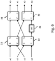
Figure 6 shows a further example of implementation of the device according to the invention. - With reference to
Fig. 1 , the system (1) for communication of signals having electromagnetic modes with orbital angular momentum (OAM) comprises asystem 1T for generation and transmission of said OAM signals and asystem 1R for reception of said OAM signals. - The
system 1 according to the present invention provides for multiplexing M transmission channels L0,L1,...,LM-1 (block 3), each one having a bandwidth B, on a single radio channel having a bandwidth C, by using an array ofN transmitting antennas 5 andN receiving antennas 6. - In this manner, reuse (M times) of the available radio channel becomes possible even in the absence of multiple propagation paths. In addition, the (vertical, horizontal, circular) polarization of the waves employed constitutes a further degree of freedom that allows further reuse of the channel.
- The
communication system 1 can be modelled as ablock 7 with M inputs and M outputs. Up to M transmitters BBTx0..BBTxM-1 (block 3), each one operating with a known modulation, are connected to said M inputs; the same number M of receivers BBRx0..BBRxM-1 are connected to said M outputs (block 9). In principle, a receiver BBRx0 receives a signal coming from a transmitter BBTx0, a receiver BBRx1 receives a signal coming from a transmitter BBTx1, and so on. However, since theblock 7 comprises a radio channel and antennas that might suffer from imperfections and parasitic couplings, the transfer matrix ofsaid block 7 will not be ideal, i.e. diagonal, but there will be mutual interferences among the different signals in the channel. Prior-art MIMO techniques can be used in order to diagonalize the transfer matrix and cancel mutual interferences. For example, "XPIC" ("Cross Polar Interference Canceller") circuits are usually employed in radio links in order to transmit two independent streams on the two polarizations (e.g. vertical and horizontal), thus implementing a 2x2 MIMO technique and doubling the capacity of the communication system. The XPIC canceller estimates the component of the vertical polarization signal that interferes with the horizontal polarization signal, and subtracts it from the latter; the same is done for the other stream. - The
N transmitting antennas 5 are arranged equally spaced on a circumference. Such a type of antenna array allows the generation of OAM modes with angular index A, where -N/2<A<N/2. - The electromagnetic signals generated by the M baseband transmitters BBTx0..BBTxM-1 are sent to the M inputs L0,L1,...,LM-1, each one of which is allocated to a respective OAM mode. The A=0 mode is the one associated with the classic flat wave. According to a typical allocation, the modes with the lowest indices are used first, since they are in any case more robust, followed by modes with progressively higher indices: A=0, 1, -1, 2, -2, and so on.
- The mapping between the OAM modes and the M input electromagnetic signals fed to the
N transmitting antennas 5 is advantageously carried out through adevice 11 according to the invention, i.e. amodal transformer TM 11 that performs a Fast Fourier transform (FFT). Although not part of the claimed invention, for easier understanding the working principle, a Discrete Fourier Transform (DFT) will also be described as an alternative to the FFT. For example, let us consider as an input signal a unitary signal at the input with index h (where 0≤h<M) of themodal transformer TM 11; it will be transformed by the DFT into a phase ramp of the exp(j2πhk/N) type at the outputs (k being the index of the DFT output). Thanks to the linearity property of the DFT, the mapping can be done simultaneously for all input electromagnetic signals L0,L1,...,LM-1. Since -N/2<A<N/2, the DFT will map the inputs h=1,...,(N/2)-1 on positive output phase ramps, and the inputs h=(N/2),...,(N-1) on negative output phase ramps. - In particular, with a unitary input h=1 a phase ramp with one cycle per period, i.e. exp(j2πk/N), which will be used for the A=1 mode, will be obtained at the DFT output; with a unitary input h=2 a phase ramp with two cycles per period will be obtained: exp(j2π2k/N), which will be used for the A=2 mode; and so on. With a unitary input h=(N-1) a negative phase ramp with one cycle per period will be obtained at the output: exp(-j2πk/N), which will be used for the A=-1 mode; with a unitary input h=N-2 a negative phase ramp with two cycles per period will be obtained at the output: exp(-j2π2k/N), which will be used for the A=-2 mode; and so on.
- For better component efficiency and/or economy, the value N is an integer power of two: this allows implementing an FFT ("Fast Fourier Transform") algorithm, which is more efficient than the DFT.
- The main FFT algorithms, referred to as "time decimation" and "frequency decimation" algorithms, utilize naturally arranged inputs and provide outputs with a "bit-reversal" arrangement (bit-reversal permutation), or vice versa: in cases of "bit-reversal" arrangement, the
communication system 1 comprises a stream permutation block for obtaining again the natural arrangement. - Downstream of the
modal transformer TM 11 there is a firstUPC frequency converter 13, i.e. an "Up-Converter". The frequency converter 13 (which is synchronous for all signals) allows obtaining output OAM signals at the frequency of the radio channel in use, i.e. it will convert the OAM signals from baseband into passband. - The frequency-converted OAM signals are sent to the N transmitting antennas 5 (AT0,AT1,...,ATN-1).
Such transmitting antennas 5 can be implemented by using any technology, e.g. dipoles, Yagi-Uda, horn, and so on. The directivity of the single antenna AT can be profitably exploited in order to improve the performance of the connection. - As regards the
reception system 1R, an array of receiving antennas 6 (AR0,AR1,...,ARN-1) can be used, which is analogous and symmetrical to the transmitting one 5. - An OAM wave with A=h mode (where -N/2<h<N/2) is received by the receiving
antennas 6 AR0,AR1,...,ARN-1, at the outputs of which a phase shift of the exp(j2πhk/N) type occurs, where k is the index of the receivingantennas 6. - Downstream of the receiving
antennas 6 there is adevice 15 which is similar to thedevice 11 according to the invention; however, in this case it is an inversemodal transformer TMI 15, which implements the inverse FFT operation (IFFT), thereby selectively returning, at its outputs L0,L1,...,LM-1, the electromagnetic signals that were transmitted on each OAM mode. Due to the linearity property of themodal transformer TM 11 and of the inversemodal transformer TMI 15, thesystem 1 can operate on multiple modes simultaneously. - Thanks to the duality property of the Fourier transform, the
same device - Between the receiving
antennas 6 and the inversemodal transformer TMI 15 there is a second DNC frequency converter 17 ("Down-Converter"), which is synchronous for all streams, with input at the frequency of the radio channel in use. SaidDNC converter 17 allows bringing the received electromagnetic signals back into baseband. The secondDNC frequency converter 17 preferably comprises a plurality (M) of frequency converters. - Preferably, between the inverse
modal transformer TMI 15 and the M receivers BBRx0..BBRxM-1 there is aninterference canceller XIC 19, which cancels any mutual interference of the signals in transit therein, i.e. it removes from each signal associated with a certain OAM mode the signals associated with other OAM modes. In other words, theinterference canceller XIC 19 performs a function which is similar to the "Cross-Polar Interference Cancellation" technique. - In the
system 1, themodal transformer TM 11 and the inversemodal transformer TMI 15 operate on complex baseband signals, typically sampled ones. The architecture of thesystem 1 can therefore be easily integrated into transmitters and/or receivers created with sampled-data numeric processing techniques. - In a second preferred embodiment of the invention, the positions of the
modal transformer TM 11 and of the firstUPC frequency converter 13 are reversed, and the same applies in reception to the secondDNC frequency converter 17 and the inversemodal transformer TMI 15. In such cases, themodal transformer TM 11 and the inversemodal transformer TMI 15 will operate at the frequency of the selected radio channel, hence with passband signals. - This makes it unnecessary to implement the second
DNC frequency converter 17 in complete form. - In fact, with reference to
Fig. 2 , if thesystem 1 transmits a multiplicity of signals, but the receiver must only select a part thereof, so that only one receiver at a time actually needs to be used, it will be possible to completely eliminate the second DNC frequency converter 17 (i.e. as aforesaid, containing M frequency converters), replacing it with just a single frequency converter, included in areceiver Rx 21, which will thus operate as a complete radio frequency receiver. - Said
receiver Rx 21 can be connected to the inversemodal transformer TMI 15 through aselector 23 allowing selection of the signal coming from the desired h-th OAM mode. - The
receiver Rx 21 may therefore be any known receiving apparatus, e.g. a conventional radio-television receiver. - The receiving
antennas 6 are advantageously independent of the technology of thereceiver Rx 21 and of the type of modulation in use. - Likewise, on the transmission side the first
UPC frequency converter 13 can be eliminated, should it not be necessary to use all the transmitters Tx0..TxM-1. - Due to the characteristics of the FFT, some of the inputs of the
modal transformer TM 11 are unused. - With reference to
Fig. 3 , the unused inputs of themodal transformer TM 11 are fed with a zero signal.Fig. 3 represents the case wherein only two transmitters, Tx0 and Tx1 (block 3) are directly connected to themodal transformer TM 11, and wherein each transmitter Tx0 and Tx1 comprises its own frequency converter ("Up Converter"). - The present invention also relates to a
device 11 for generating OAM signals, i.e. themodal transformer TM 11 and the inversemodal transformer TMI 15. - Both the
modal transformer TM 11 and the inversemodal transformer TMI 15 comprise analog components (stages) arranged in cascade. Synthesis of such stages is obtained by using the sampled baseband data FFT processing methodology. However, in the present invention the synthesis technique is applied within a very different frame, i.e. to analog or anyway passband radio frequency circuits, as opposed to baseband digital signals, and to continuous signals as opposed to sampled signals. Moreover, the FFT is traditionally executed either en bloc or by discrete steps, since digital processors are used. In the present invention, instead, analog signals flow in a continuous stream through the circuits that apply the transform. - The FFT algorithm can be implemented through a series of n stages with n=log2(N) (where N is the number of inputs), each one of which only consists of complex sums of two operands, and complex products by a pure phase constant.
- The present invention preferably implements this property in passband, thereby attaining the useful result that the
modal transformer TM 11 and the inversemodal transformer TMI 15 comprise radio frequency combiners/dividers and phase shifters. - This provides a large bandwidth for the
modal transformer TM 11 and the inversemodal transformer TMI 15, which will only be limited by the performance of the analog RF components employed. For example, a millimeter wave application may ensure bandwidths of tens of gigahertz, which could not be attained in real time with digital circuits. - With reference to
Fig. 4 , there is shown one example of a flow graph that applies the FFT to 4 input values, x0,x1,x2,x3, and returns four output values XO,X2,X1,X3. Note that the order of the output values is not the natural (original) progressive one, being of the "bit-reversal" type. This FFT is based on log2(4)=2 stages. - The phase terms are defined as follows:

- The index N is the aforementioned number of inputs of the FFT; r is the exponent to which the basic complex exponential WN is raised in classic "time decimation" and "frequency decimation" FFT algorithms.
- With reference to
Fig. 5 , the flow graph ofFig. 4 is implemented with radiofrequency analog components frequency analog components first nodes 25, from which two branches extend, which are implemented as radiofrequency signal dividers 25, andsecond nodes subtractors 27 or adders 26). The coefficient -1 (reference 29 inFig. 4 ) can be implemented, in fact, as adivider 25 having an output with a 180° phase, or as the input of acombiner 
- The multiplication by the
term 
frequency phase shifter 31 with a -90° phase or, likewise, a +270° phase. The analogradio frequency components phase shifter 31. - The
phase shifter 31 is preferably implemented through a delay line, or is obtained by using an output of adivider 25 configured for obtaining a 90° phase, plus a 180° phase inversion or, respectively, by using the input of acombiner - Reordering of the output signals having values XO,X2,X1,X3 is attained by connecting the cables of the
N transmitting antennas 5 in numerical order, as opposed to the positional order. - Other simplifications are also possible, and will still fall within the scope of the present invention.
- With reference to
Fig. 6 , the following will illustrate a further example of implementation of thedevice Fig. 5 . - In the circuit of
Fig. 6 a combiner/divider component 33 is introduced, which simultaneously provides the sum (S) and the difference (J) of the signals at theinputs components 33 will replace twodividers 25 and twocombiners Fig. 5 ; therefore, four combiner/divider components 33 will replace sixteen of them. - High-
frequency dividers 25,combiners phase shifters 31 and combiners/dividers 33 can be implemented by using various techniques and circuit solutions, whether passive or active, including transformers, couplers, concentrated-constant artificial lines, and so on. Such techniques and solutions will still fall within the idea of the present invention. By using analogradio frequency components Fig. 4 , thesame analog components - Finally, from an application viewpoint, the system for transmission and/or reception of signals having OAM electromagnetic modes, and the related device and method, of the present invention can also be used, in addition to radio communications, for applications ranging from remote sensing to passive radiometry (e.g. geophysical prospection, spectroscopy for chemical analyses, medical diagnostics, and so on), from radio frequency to microwaves, and more. In fact, although the present invention has been described herein with reference to electromagnetic signals emitted by a transmitter and inputted to the
device 11 during transmission, electromagnetic signals may also be received from further emitters, e.g. natural sources to be subjected to passive radiometry. - The features of the present invention, as well as the advantages thereof, are apparent from the above description.
- A first advantage of the present invention is that OAM signals are obtained by means of the Fast Fourier transform.
- A second advantage of the present invention is that the second DNC frequency converter needs not be implemented in complete form, if the system provides for transmitting a multiplicity of signals and receiving only a part thereof.
- A further advantage of the present invention is that the receiver Rx may be any prior-art receiving apparatus, in particular a conventional radio-television receiver.
- A further advantage of the present invention is that the first UPC frequency converter can be omitted in transmission since there are unused inputs at the modal transformer TM.
- A further advantage of the present invention is that a large bandwidth is obtained for the modal transformer TM and the inverse modal transformer TMI, which is only limited by the performance of the analog radio frequency components in use.
- A further advantage of the present invention is that it uses the same analog radio frequency components for executing both the FFT algorithm and the IFFT.
- The method for generating and transmitting signals having electromagnetic modes with orbital angular momentum provides for generating said OAM signals through the
device 11. - The method for reception of OAM signals provides for receiving the OAM signals through the
device 15, applying an inverse Fast Fourier transform to the OAM signals through saiddevice 15, and obtaining at the output of thedevice 15 the electromagnetic signals that were transmitted by at least onetransmitter 3. - The method also provides for applying the Fast Fourier transform and/or the inverse Fast Fourier transform through the
analog components particular combiners dividers 25,phase shifter 31 and combiner/divider components 33. - The system for transmission and/or reception of signals having electromagnetic modes with orbital angular momentum and the related device and method described herein by way of example may be subject to many possible variations without departing from the scope of the claims; it is also clear that in the practical implementation of the invention the illustrated details may have different shapes or be replaced with other elements within the scope of the claims.
- It can therefore be easily understood that the present invention is not limited to a system for transmission and/or reception of signals having electromagnetic modes with orbital angular momentum and the related device and method, but may be subject to many modifications within the scope specified in the following claims.
Claims (18)
- Device (11) for generating and transmitting input signals over radio signals having electromagnetic modes with orbital angular momentum, wherein said device (11) is configured to:receive, at its input ports, a plurality of input signals from at least one signal source;generate output signals by applying a Fast Fourier Transform to said plurality of input signals by means of a Fast Fourier Transform module;provide said output signals to output ports connected to corresponding transmitting antennas (5), and radio transmit said output signals by said transmitting antennas so that during radio transmission the transmitted output signals have at least one orbital angular momentum due to the application of said Fast Fourier Transform;wherein the number M of the input signals applied to said input ports is smaller than the number N of said output signals produced by said device.
- Device (11) according to claim 1, wherein said device (11) is a modal transformer (11) comprising analog components (25,26,27,31,33), including at least one of a combiner or a divider or a phase shifter, so configured to generate, in combination, a set of output signals being the Fast Fourier Transform of said input signals.
- Device according to claim 1 or 2, wherein said input signals or said output signals occupy substantially a same baseband or passband frequency.
- Device according to any one of claims 1 to 3, wherein said input signals are radio-television signals or signals for passive radiometry or remote sensing applications.
- System (1T) for generating and transmitting input signals over radio signals having electromagnetic modes with orbital angular momentum, OAM, said system (1T) comprising:at least one signal source configured to generate a plurality of input signals; anda device (11) according to one or more of claims 1 to 4.
- System according to claim 5, wherein said system comprises a first frequency converter (13) interposed between the output ports of said device and said plurality of transmitting antennas, said first frequency converter being configured to convert the output signals generated by said device from baseband into passband.
- System according to claim 5, wherein said system comprises a first frequency converter (13) interposed between said at least one signal source and said device, said first frequency converter being configured to convert said input signals from baseband into passband.
- System according to claim 7, wherein said device is configured to operate at a frequency of a selected radio channel with passband signals.
- Device (15) for receiving a plurality of communication signals transmitted over radio signals having electromagnetic modes with different orbital angular momentums, wherein said device (15) is configured to:receive said radio signals over a plurality of receiving antennas (6);provide each of said received signals to corresponding input ports of an inverse Fast Fourier Transform module;apply an inverse Fast Fourier Transform to said received signals by said module in order to obtain, at its output ports, said communication signals for being transferred to at least one receiver of communication signals,wherein the number M of said communication signals is smaller than the number N of the receiving antennas of the device.
- Device (15) according to claim 9, wherein said module is an inverse modal transformer (15) comprising analog components (25,26,27,31,33), including at least one of a combiner or a divider or a phase shifter, so configured to generate, in combination, a set of output signals being the inverse Fast Fourier Transform of said received signals.
- Device according to claim 9 or 10, wherein said radio signals or said communication signals occupy substantially a same baseband or passband frequency.
- Device according to any one of claims 9 to 11, wherein said communication signals are radio-television signals or signals for passive radiometry or remote sensing applications.
- System (1R) for receiving communication signals transmitted over radio signals having electromagnetic modes with orbital angular momentum, said system (1R) comprising:a plurality of receiving antennas (6);a device (15) according to one or more of claims 9 to 12 configured to receive said radio signals through said plurality of receiving antennas, andat least one receiver of communications signals connected to the output ports of said device.
- System (1R) according to claim 13, wherein said system (1R) comprises a second frequency converter (17) interposed between the output ports of said device and said at least one receiver, being configured to convert said communication signals into baseband.
- System according to claim 13, wherein said system comprises a second frequency converter interposed between said plurality of receiving antennas and the input ports of said device, being configured to convert said received signals into baseband.
- System according to any one of claims 13 to 15, further comprising an interference canceller (19), between the output ports of said device and said at least one receiver, being configured to cancel any mutual interference of the signals in transit therein.
- A method of generating and transmitting input signals over radio signals having electromagnetic modes with different orbital angular momentums, wherein said method comprises:receiving, at the input ports of a Fast Fourier Transform module, input signals from at least one signal source;applying to said input signals a Fast Fourier Transform by said module to generate output signals;providing said output signals of said module to corresponding output ports connected to corresponding transmitting antennas (5), and radio transmitting said output signals by saidtransmitting antennas so that during radio transmission the transmitted output signals have at least one orbital angular momentum due to the application of said Fast Fourier Transform,wherein the number M of said input signals fed to said input ports is smaller than the number N of said output signals.
- A method for receiving a plurality of communication signals transmitted over radio signals having electromagnetic modes with different orbital angular momentums, wherein said method comprises:receiving said radio signals over a plurality of receiving antennas (6);providing each of said received signals to corresponding input ports of an inverse Fast Fourier Transform module;applying an inverse Fast Fourier Transform to said received signals by said module to obtain, at its output ports, said communication signals for being transferred to at least one receiver of communication signals,wherein the number M of said communication signals is smaller than the number N of the receiving antennas.
Applications Claiming Priority (2)
| Application Number | Priority Date | Filing Date | Title |
|---|---|---|---|
| ITTO20140328 | 2014-04-17 | ||
| PCT/IB2015/052813 WO2015159264A1 (en) | 2014-04-17 | 2015-04-17 | System for transmission and/or reception of signals having electromagnetic modes with orbital angular momentum, and device and method thereof |
Publications (2)
| Publication Number | Publication Date |
|---|---|
| EP3132558A1 EP3132558A1 (en) | 2017-02-22 |
| EP3132558B1 true EP3132558B1 (en) | 2021-04-07 |
Family
ID=50983029
Family Applications (1)
| Application Number | Title | Priority Date | Filing Date |
|---|---|---|---|
| EP15724054.0A Active EP3132558B1 (en) | 2014-04-17 | 2015-04-17 | System for transmission and/or reception of signals having electromagnetic modes with orbital angular momentum, and device and method thereof |
Country Status (6)
| Country | Link |
|---|---|
| US (1) | US10665960B2 (en) |
| EP (1) | EP3132558B1 (en) |
| JP (2) | JP2017515337A (en) |
| KR (1) | KR20160146850A (en) |
| CN (1) | CN106233659B (en) |
| WO (1) | WO2015159264A1 (en) |
Families Citing this family (30)
| Publication number | Priority date | Publication date | Assignee | Title |
|---|---|---|---|---|
| KR102004778B1 (en) * | 2013-04-19 | 2019-07-29 | 삼성전기주식회사 | Composite electronic component, board having the same mounted thereon and power smoothing unit comprising the same |
| KR102069627B1 (en) * | 2013-10-31 | 2020-01-23 | 삼성전기주식회사 | Composite electronic component and board for mounting the same |
| KR102004770B1 (en) * | 2013-10-31 | 2019-07-29 | 삼성전기주식회사 | Composite electronic component and board for mounting the same |
| US10291300B2 (en) * | 2015-12-07 | 2019-05-14 | University Of Southern California | Systems and techniques for communication using multiple-input-multiple-output processing of orbital angular momentum modes |
| CN106130655B (en) * | 2016-06-30 | 2018-04-24 | 中国科学院上海微系统与信息技术研究所 | A kind of multi-modal orbital angular momentum multiplex communication system and method |
| JP6996563B2 (en) * | 2017-09-25 | 2022-01-17 | 日本電信電話株式会社 | OAM multiplex communication system and OAM multiplex communication method |
| WO2019078547A1 (en) * | 2017-10-17 | 2019-04-25 | 한국과학기술원 | Method for estimating and compensating for imbalance between rf chains in uca-based oam system |
| CN108134756B (en) * | 2017-12-15 | 2020-06-16 | 西安电子科技大学 | Wireless Communication System Based on Vortex Electromagnetic Wave and Orthogonal Frequency Division Multiplexing |
| EP3780430B1 (en) * | 2018-03-30 | 2025-01-15 | Nippon Telegraph And Telephone Corporation | Oam multiplexed communication system and inter-mode interference compensation method |
| JP7028314B2 (en) * | 2018-03-30 | 2022-03-02 | 日本電信電話株式会社 | OAM multiplex communication system and inter-mode interference elimination method |
| US10715243B2 (en) * | 2018-10-19 | 2020-07-14 | Huawei Technologies Co., Ltd. | Pseudo-doppler receiving architecture for OAM and MIMO transmissions |
| US11438032B2 (en) | 2018-11-02 | 2022-09-06 | Nec Corporation | OAM reception apparatus, OAM reception method, and OAM transmission system |
| CN109546319B (en) * | 2018-11-13 | 2022-03-15 | 电子科技大学 | Electromagnetic vortex generator based on multi-arm spiral structure |
| CN110266354B (en) * | 2019-06-12 | 2021-05-18 | 西安电子科技大学 | Signal receiving method of orbital angular momentum wireless communication system |
| EP3985887B1 (en) * | 2019-06-28 | 2023-06-07 | LG Electronics Inc. | Method for transmitting and receiving signal in optical wireless communication system, and transmitting terminal and receiving terminal therefor |
| JP7306205B2 (en) * | 2019-10-03 | 2023-07-11 | 日本電気株式会社 | OAM RECEIVER, OAM RECEPTION METHOD, AND OAM TRANSMISSION SYSTEM |
| CN114450892B (en) * | 2019-10-03 | 2023-07-25 | 三菱电机株式会社 | Interference signal generation circuit, interference removal device, method, and program storage medium |
| CN112803975B (en) | 2019-11-14 | 2022-02-25 | 华为技术有限公司 | Method, equipment and system for determining precoding matrix |
| CN112887989B (en) * | 2019-11-30 | 2023-03-03 | 华为技术有限公司 | OAM-based communication method, related equipment and storage medium |
| JP7665922B2 (en) | 2020-04-08 | 2025-04-22 | 日本電気株式会社 | Signal estimation device, signal estimation method, and computer program |
| US11088752B1 (en) * | 2020-05-29 | 2021-08-10 | Huawei Technologies Co., Ltd. | Mobile pseudo-doppler OAM radio downlink system |
| CN111740223B (en) * | 2020-07-06 | 2021-05-28 | 中国科学院成都生物研究所 | A Method for Synthesizing Vortex Electromagnetic Fields with High Orbital Angular Momentum Mode Numbers |
| CN112235019B (en) * | 2020-09-28 | 2023-08-01 | 西安理工大学 | A wireless encrypted green transmission system based on vortex electromagnetic wave technology |
| KR102399977B1 (en) * | 2020-10-07 | 2022-05-18 | 금오공과대학교 산학협력단 | Method for transmitting wireless communication signals |
| KR102377039B1 (en) | 2020-10-12 | 2022-03-21 | 국방과학연구소 | Directional coupler for orbital angular momentum mode |
| WO2022261883A1 (en) * | 2021-06-17 | 2022-12-22 | Qualcomm Incorporated | Radial modes for oam mimo communication |
| US12621049B2 (en) * | 2021-07-13 | 2026-05-05 | Qualcomm Incorporated | Transmit diversity across orbital angular momentum modes |
| US20240380509A1 (en) * | 2021-08-20 | 2024-11-14 | Beijing Xiaomi Mobile Software Co., Ltd. | Orbital angular momentum (oam)-based communication method and apparatus |
| WO2023060500A1 (en) * | 2021-10-14 | 2023-04-20 | Qualcomm Incorporated | Multimode discontinuous reception in orbital angular momentum communications |
| JP7691023B2 (en) * | 2022-02-22 | 2025-06-11 | 日本電信電話株式会社 | Transmitting Device |
Family Cites Families (25)
| Publication number | Priority date | Publication date | Assignee | Title |
|---|---|---|---|---|
| MX9505173A (en) | 1995-07-19 | 1997-05-31 | Radio Frequency Systems Inc | Power sharing system for rf amplifiers. |
| JP3727406B2 (en) | 1996-03-07 | 2005-12-14 | 株式会社日立国際電気 | Function conversion operator |
| JP4722752B2 (en) | 2006-04-11 | 2011-07-13 | 日本電信電話株式会社 | OFDM signal receiver |
| JP5264933B2 (en) | 2008-01-18 | 2013-08-14 | コーニンクレッカ フィリップス エレクトロニクス エヌ ヴィ | Nuclear magnetic resonance spectroscopy using light with orbital angular momentum. |
| US7701381B2 (en) * | 2008-07-18 | 2010-04-20 | Raytheon Company | System and method of orbital angular momentum (OAM) diverse signal processing using classical beams |
| CN101345556A (en) * | 2008-08-11 | 2009-01-14 | 北京航空航天大学 | Wireless Communication System Carrying Orbital Angular Momentum Electromagnetic Beams |
| CN102859384A (en) | 2010-04-22 | 2013-01-02 | 皇家飞利浦电子股份有限公司 | Nuclear magnetic resonance magnetometer employing optically induced hyperpolarization |
| EP2656442A1 (en) * | 2010-12-22 | 2013-10-30 | Telefonaktiebolaget LM Ericsson (PUBL) | An antenna arrangement |
| US8432884B1 (en) * | 2011-11-16 | 2013-04-30 | Metropcs Wireless, Inc. | System and method for increased bandwidth efficiency within microwave backhaul of a telecommunication system |
| US8917745B2 (en) * | 2012-03-11 | 2014-12-23 | Broadcom Corporation | Channel bonding with orbital angular momentum |
| US9240956B2 (en) * | 2012-03-11 | 2016-01-19 | Broadcom Corporation | Communication system using orbital angular momentum |
| EP2878109B1 (en) * | 2012-07-24 | 2016-06-01 | Eutelsat SA | Modulation technique for transmitting and receiving radio vortices |
| WO2014104911A1 (en) * | 2012-12-26 | 2014-07-03 | Huawei Technologies Co., Ltd | Method and apparatus for generating electromagnetic beams |
| ITAR20130023A1 (en) * | 2013-07-01 | 2015-01-02 | Marco Matteoni | SYSTEM FOR THE GENERATION AND MANAGEMENT OF ORBITAL ANGLE MOMENT IN ELECTROMAGNETIC RADIATION USING SPECIAL LENSES - SYSTEM FOR GENERATION AND MANAGEMENT OF ORBITAL ANGULAR MOMENTUM IN AN ELECTROMAGNETIC RADIATION BY MEANS |
| DK3066777T3 (en) * | 2013-11-05 | 2018-11-05 | Eutelsat Sa | SYSTEM FOR SENDING AND RECEIVING RADIO FREQUENCY SIGNALS CARRYING COMPLEX HARMONIC MODES |
| WO2015189653A1 (en) * | 2014-06-10 | 2015-12-17 | Eutelsat S A | Ofdm based orbital angular momentum system and method |
| FR3014271B1 (en) * | 2013-11-29 | 2015-12-04 | Inst Nat Sciences Appliq | METHOD FOR TRANSMITTING A SEQUENCE OF DATA SYMBOLS, TRANSMISSION DEVICE, SIGNAL, RECEPTION METHOD, RECEIVING DEVICE, AND CORRESPONDING COMPUTER PROGRAM |
| KR20150079039A (en) * | 2013-12-31 | 2015-07-08 | 한국전자통신연구원 | Apparatus and method for simultaneous transmission or receiving of orbital angular momentum modes |
| US9031151B1 (en) * | 2014-05-07 | 2015-05-12 | L-3 Communications, Corp. | Receiving and resolving a composite orbital angular momentum beam |
| US9413448B2 (en) * | 2014-08-08 | 2016-08-09 | Nxgen Partners Ip, Llc | Systems and methods for focusing beams with mode division multiplexing |
| US10516486B2 (en) * | 2014-08-08 | 2019-12-24 | Nxgen Partners Ip, Llc | Modulation and multiple access technique using orbital angular momentum |
| US9998187B2 (en) * | 2014-10-13 | 2018-06-12 | Nxgen Partners Ip, Llc | System and method for combining MIMO and mode-division multiplexing |
| US10103799B2 (en) * | 2015-03-16 | 2018-10-16 | Lockheed Martin Corporation | Apparatus and method for increased data rates in underwater communications using orbital angular momentum |
| US10511092B2 (en) * | 2015-10-27 | 2019-12-17 | Intel Corporation | Orbital angular momentum in millimeter-wave wireless communication |
| US10291300B2 (en) * | 2015-12-07 | 2019-05-14 | University Of Southern California | Systems and techniques for communication using multiple-input-multiple-output processing of orbital angular momentum modes |
-
2015
- 2015-04-17 WO PCT/IB2015/052813 patent/WO2015159264A1/en not_active Ceased
- 2015-04-17 JP JP2016557319A patent/JP2017515337A/en active Pending
- 2015-04-17 US US15/127,588 patent/US10665960B2/en active Active
- 2015-04-17 CN CN201580019696.5A patent/CN106233659B/en active Active
- 2015-04-17 KR KR1020167032042A patent/KR20160146850A/en not_active Withdrawn
- 2015-04-17 EP EP15724054.0A patent/EP3132558B1/en active Active
-
2019
- 2019-10-10 JP JP2019186771A patent/JP7056857B2/en active Active
Non-Patent Citations (2)
| Title |
|---|
| "Utilization of photon orbital angular momentum in the low-frequency radio domain", 2 March 2009, article B THIDÉ ET AL: "Utilization of photon orbital angular momentum in the low-frequency radio domain", pages: 85, XP055108309, DOI: 10.1103/PhysRevLett.99.087701 * |
| OVE EDFORS ET AL: "Is Orbital Angular Momentum (OAM) Based Radio Communication an Unexploited Area?", IEEE TRANSACTIONS ON ANTENNAS AND PROPAGATION, IEEE SERVICE CENTER, PISCATAWAY, NJ, US, vol. 60, no. 2, 1 February 2012 (2012-02-01), pages 1126 - 1131, XP011403555, ISSN: 0018-926X, DOI: 10.1109/TAP.2011.2173142 * |
Also Published As
| Publication number | Publication date |
|---|---|
| KR20160146850A (en) | 2016-12-21 |
| JP2020039129A (en) | 2020-03-12 |
| US10665960B2 (en) | 2020-05-26 |
| CN106233659B (en) | 2020-10-09 |
| US20170170574A1 (en) | 2017-06-15 |
| CN106233659A (en) | 2016-12-14 |
| JP7056857B2 (en) | 2022-04-19 |
| JP2017515337A (en) | 2017-06-08 |
| EP3132558A1 (en) | 2017-02-22 |
| WO2015159264A1 (en) | 2015-10-22 |
Similar Documents
| Publication | Publication Date | Title |
|---|---|---|
| US10665960B2 (en) | System for transmission and/or reception of signals having electromagnetic modes with orbital angular momentum, and device and method thereof | |
| CN111133698B (en) | OAM multiplex communication system and OAM multiplex communication method | |
| Chen et al. | A 2-D FFT-based transceiver architecture for OAM-OFDM systems with UCA antennas | |
| CN106130655B (en) | A kind of multi-modal orbital angular momentum multiplex communication system and method | |
| CN106130654B (en) | A kind of vortex electromagnetism wave generation device and method | |
| CN111698183B (en) | Multi-mode vortex wave orthogonalization self-adaptive transmission method and device | |
| Jamali et al. | Scalable and energy-efficient millimeter massive MIMO architectures: Reflect-array and transmit-array antennas | |
| Cheng et al. | Quasi-fractal UCA-based OAM for highly efficient orthogonal transmission | |
| WO2009076223A1 (en) | Transforming signals using passive circuits | |
| Hei et al. | Energy-efficient hybrid precoding for mmWave MIMO systems with phase modulation array | |
| Zhang et al. | Structured beamforming based on orbital angular momentum mode-group | |
| Deng et al. | MmWave multiuser MIMO precoding with fixed subarrays and quantized phase shifters | |
| CN111953393A (en) | Massive MIMO Hybrid Precoder and Matching Relationship | |
| Wang | Joint transmitter and receiver design for uplink MU-MIMO systems with dynamic metasurface antennas | |
| Nerini et al. | MIMO systems aided by microwave linear analog computers: Capacity-achieving architectures with reduced circuit complexity | |
| Ahmad et al. | Low RF-complexity digital transmit beamforming for large-scale millimeter wave MIMO systems | |
| Momen‐Tayefeh et al. | Optimizing hybrid beamforming in millimeter‐wave massive multiple‐input multiple‐output systems: A gradient projection approach | |
| Nosrati et al. | Switch-based hybrid precoding in mmWave massive MIMO systems | |
| Jie et al. | Two-ray multipath propagation of MIMO-based OAM radio communications | |
| US12335003B2 (en) | Distributed digital beamforming | |
| Yan et al. | Dynamic-subarray with quantized-and fixed-phase shifters for terahertz hybrid beamforming | |
| Murata et al. | OAM multiplexing using uniform circular array and microwave circuit for short‐range communication | |
| WO2023065005A1 (en) | Methods and systems to produce fully-connected optical beamforming | |
| Nsenga et al. | Joint tx/rx analog linear transformation for maximizing the capacity at 60 GHz | |
| Koh et al. | Time-interleaved phased arrays with parallel signal processing in RF modulations |
Legal Events
| Date | Code | Title | Description |
|---|---|---|---|
| STAA | Information on the status of an ep patent application or granted ep patent |
Free format text: STATUS: THE INTERNATIONAL PUBLICATION HAS BEEN MADE |
|
| PUAI | Public reference made under article 153(3) epc to a published international application that has entered the european phase |
Free format text: ORIGINAL CODE: 0009012 |
|
| STAA | Information on the status of an ep patent application or granted ep patent |
Free format text: STATUS: REQUEST FOR EXAMINATION WAS MADE |
|
| 17P | Request for examination filed |
Effective date: 20161021 |
|
| AK | Designated contracting states |
Kind code of ref document: A1 Designated state(s): AL AT BE BG CH CY CZ DE DK EE ES FI FR GB GR HR HU IE IS IT LI LT LU LV MC MK MT NL NO PL PT RO RS SE SI SK SM TR |
|
| AX | Request for extension of the european patent |
Extension state: BA ME |
|
| DAV | Request for validation of the european patent (deleted) | ||
| DAX | Request for extension of the european patent (deleted) | ||
| STAA | Information on the status of an ep patent application or granted ep patent |
Free format text: STATUS: EXAMINATION IS IN PROGRESS |
|
| 17Q | First examination report despatched |
Effective date: 20190603 |
|
| RIC1 | Information provided on ipc code assigned before grant |
Ipc: H04L 5/04 20060101AFI20200930BHEP Ipc: H01Q 21/20 20060101ALN20200930BHEP |
|
| GRAP | Despatch of communication of intention to grant a patent |
Free format text: ORIGINAL CODE: EPIDOSNIGR1 |
|
| STAA | Information on the status of an ep patent application or granted ep patent |
Free format text: STATUS: GRANT OF PATENT IS INTENDED |
|
| INTG | Intention to grant announced |
Effective date: 20201113 |
|
| GRAS | Grant fee paid |
Free format text: ORIGINAL CODE: EPIDOSNIGR3 |
|
| GRAA | (expected) grant |
Free format text: ORIGINAL CODE: 0009210 |
|
| STAA | Information on the status of an ep patent application or granted ep patent |
Free format text: STATUS: THE PATENT HAS BEEN GRANTED |
|
| AK | Designated contracting states |
Kind code of ref document: B1 Designated state(s): AL AT BE BG CH CY CZ DE DK EE ES FI FR GB GR HR HU IE IS IT LI LT LU LV MC MK MT NL NO PL PT RO RS SE SI SK SM TR |
|
| REG | Reference to a national code |
Ref country code: GB Ref legal event code: FG4D |
|
| REG | Reference to a national code |
Ref country code: AT Ref legal event code: REF Ref document number: 1381077 Country of ref document: AT Kind code of ref document: T Effective date: 20210415 Ref country code: CH Ref legal event code: EP |
|
| REG | Reference to a national code |
Ref country code: DE Ref legal event code: R096 Ref document number: 602015067741 Country of ref document: DE |
|
| REG | Reference to a national code |
Ref country code: IE Ref legal event code: FG4D |
|
| REG | Reference to a national code |
Ref country code: LT Ref legal event code: MG9D |
|
| REG | Reference to a national code |
Ref country code: NL Ref legal event code: MP Effective date: 20210407 Ref country code: AT Ref legal event code: MK05 Ref document number: 1381077 Country of ref document: AT Kind code of ref document: T Effective date: 20210407 |
|
| PG25 | Lapsed in a contracting state [announced via postgrant information from national office to epo] |
Ref country code: BG Free format text: LAPSE BECAUSE OF FAILURE TO SUBMIT A TRANSLATION OF THE DESCRIPTION OR TO PAY THE FEE WITHIN THE PRESCRIBED TIME-LIMIT Effective date: 20210707 Ref country code: AT Free format text: LAPSE BECAUSE OF FAILURE TO SUBMIT A TRANSLATION OF THE DESCRIPTION OR TO PAY THE FEE WITHIN THE PRESCRIBED TIME-LIMIT Effective date: 20210407 Ref country code: HR Free format text: LAPSE BECAUSE OF FAILURE TO SUBMIT A TRANSLATION OF THE DESCRIPTION OR TO PAY THE FEE WITHIN THE PRESCRIBED TIME-LIMIT Effective date: 20210407 Ref country code: FI Free format text: LAPSE BECAUSE OF FAILURE TO SUBMIT A TRANSLATION OF THE DESCRIPTION OR TO PAY THE FEE WITHIN THE PRESCRIBED TIME-LIMIT Effective date: 20210407 Ref country code: NL Free format text: LAPSE BECAUSE OF FAILURE TO SUBMIT A TRANSLATION OF THE DESCRIPTION OR TO PAY THE FEE WITHIN THE PRESCRIBED TIME-LIMIT Effective date: 20210407 Ref country code: LT Free format text: LAPSE BECAUSE OF FAILURE TO SUBMIT A TRANSLATION OF THE DESCRIPTION OR TO PAY THE FEE WITHIN THE PRESCRIBED TIME-LIMIT Effective date: 20210407 |
|
| PG25 | Lapsed in a contracting state [announced via postgrant information from national office to epo] |
Ref country code: GR Free format text: LAPSE BECAUSE OF FAILURE TO SUBMIT A TRANSLATION OF THE DESCRIPTION OR TO PAY THE FEE WITHIN THE PRESCRIBED TIME-LIMIT Effective date: 20210708 Ref country code: LV Free format text: LAPSE BECAUSE OF FAILURE TO SUBMIT A TRANSLATION OF THE DESCRIPTION OR TO PAY THE FEE WITHIN THE PRESCRIBED TIME-LIMIT Effective date: 20210407 Ref country code: IS Free format text: LAPSE BECAUSE OF FAILURE TO SUBMIT A TRANSLATION OF THE DESCRIPTION OR TO PAY THE FEE WITHIN THE PRESCRIBED TIME-LIMIT Effective date: 20210807 Ref country code: ES Free format text: LAPSE BECAUSE OF FAILURE TO SUBMIT A TRANSLATION OF THE DESCRIPTION OR TO PAY THE FEE WITHIN THE PRESCRIBED TIME-LIMIT Effective date: 20210407 Ref country code: PT Free format text: LAPSE BECAUSE OF FAILURE TO SUBMIT A TRANSLATION OF THE DESCRIPTION OR TO PAY THE FEE WITHIN THE PRESCRIBED TIME-LIMIT Effective date: 20210809 Ref country code: PL Free format text: LAPSE BECAUSE OF FAILURE TO SUBMIT A TRANSLATION OF THE DESCRIPTION OR TO PAY THE FEE WITHIN THE PRESCRIBED TIME-LIMIT Effective date: 20210407 Ref country code: NO Free format text: LAPSE BECAUSE OF FAILURE TO SUBMIT A TRANSLATION OF THE DESCRIPTION OR TO PAY THE FEE WITHIN THE PRESCRIBED TIME-LIMIT Effective date: 20210707 Ref country code: SE Free format text: LAPSE BECAUSE OF FAILURE TO SUBMIT A TRANSLATION OF THE DESCRIPTION OR TO PAY THE FEE WITHIN THE PRESCRIBED TIME-LIMIT Effective date: 20210407 Ref country code: RS Free format text: LAPSE BECAUSE OF FAILURE TO SUBMIT A TRANSLATION OF THE DESCRIPTION OR TO PAY THE FEE WITHIN THE PRESCRIBED TIME-LIMIT Effective date: 20210407 |
|
| PG25 | Lapsed in a contracting state [announced via postgrant information from national office to epo] |
Ref country code: LU Free format text: LAPSE BECAUSE OF NON-PAYMENT OF DUE FEES Effective date: 20210417 |
|
| REG | Reference to a national code |
Ref country code: DE Ref legal event code: R097 Ref document number: 602015067741 Country of ref document: DE |
|
| REG | Reference to a national code |
Ref country code: BE Ref legal event code: MM Effective date: 20210430 |
|
| PG25 | Lapsed in a contracting state [announced via postgrant information from national office to epo] |
Ref country code: MC Free format text: LAPSE BECAUSE OF FAILURE TO SUBMIT A TRANSLATION OF THE DESCRIPTION OR TO PAY THE FEE WITHIN THE PRESCRIBED TIME-LIMIT Effective date: 20210407 Ref country code: LI Free format text: LAPSE BECAUSE OF NON-PAYMENT OF DUE FEES Effective date: 20210430 Ref country code: CH Free format text: LAPSE BECAUSE OF NON-PAYMENT OF DUE FEES Effective date: 20210430 Ref country code: RO Free format text: LAPSE BECAUSE OF FAILURE TO SUBMIT A TRANSLATION OF THE DESCRIPTION OR TO PAY THE FEE WITHIN THE PRESCRIBED TIME-LIMIT Effective date: 20210407 Ref country code: SK Free format text: LAPSE BECAUSE OF FAILURE TO SUBMIT A TRANSLATION OF THE DESCRIPTION OR TO PAY THE FEE WITHIN THE PRESCRIBED TIME-LIMIT Effective date: 20210407 Ref country code: SM Free format text: LAPSE BECAUSE OF FAILURE TO SUBMIT A TRANSLATION OF THE DESCRIPTION OR TO PAY THE FEE WITHIN THE PRESCRIBED TIME-LIMIT Effective date: 20210407 Ref country code: CZ Free format text: LAPSE BECAUSE OF FAILURE TO SUBMIT A TRANSLATION OF THE DESCRIPTION OR TO PAY THE FEE WITHIN THE PRESCRIBED TIME-LIMIT Effective date: 20210407 Ref country code: EE Free format text: LAPSE BECAUSE OF FAILURE TO SUBMIT A TRANSLATION OF THE DESCRIPTION OR TO PAY THE FEE WITHIN THE PRESCRIBED TIME-LIMIT Effective date: 20210407 Ref country code: DK Free format text: LAPSE BECAUSE OF FAILURE TO SUBMIT A TRANSLATION OF THE DESCRIPTION OR TO PAY THE FEE WITHIN THE PRESCRIBED TIME-LIMIT Effective date: 20210407 |
|
| PLBE | No opposition filed within time limit |
Free format text: ORIGINAL CODE: 0009261 |
|
| STAA | Information on the status of an ep patent application or granted ep patent |
Free format text: STATUS: NO OPPOSITION FILED WITHIN TIME LIMIT |
|
| 26N | No opposition filed |
Effective date: 20220110 |
|
| PG25 | Lapsed in a contracting state [announced via postgrant information from national office to epo] |
Ref country code: IE Free format text: LAPSE BECAUSE OF NON-PAYMENT OF DUE FEES Effective date: 20210417 |
|
| PG25 | Lapsed in a contracting state [announced via postgrant information from national office to epo] |
Ref country code: IS Free format text: LAPSE BECAUSE OF FAILURE TO SUBMIT A TRANSLATION OF THE DESCRIPTION OR TO PAY THE FEE WITHIN THE PRESCRIBED TIME-LIMIT Effective date: 20210807 Ref country code: AL Free format text: LAPSE BECAUSE OF FAILURE TO SUBMIT A TRANSLATION OF THE DESCRIPTION OR TO PAY THE FEE WITHIN THE PRESCRIBED TIME-LIMIT Effective date: 20210407 |
|
| PG25 | Lapsed in a contracting state [announced via postgrant information from national office to epo] |
Ref country code: BE Free format text: LAPSE BECAUSE OF NON-PAYMENT OF DUE FEES Effective date: 20210430 |
|
| PG25 | Lapsed in a contracting state [announced via postgrant information from national office to epo] |
Ref country code: HU Free format text: LAPSE BECAUSE OF FAILURE TO SUBMIT A TRANSLATION OF THE DESCRIPTION OR TO PAY THE FEE WITHIN THE PRESCRIBED TIME-LIMIT; INVALID AB INITIO Effective date: 20150417 |
|
| P01 | Opt-out of the competence of the unified patent court (upc) registered |
Effective date: 20230330 |
|
| PG25 | Lapsed in a contracting state [announced via postgrant information from national office to epo] |
Ref country code: CY Free format text: LAPSE BECAUSE OF FAILURE TO SUBMIT A TRANSLATION OF THE DESCRIPTION OR TO PAY THE FEE WITHIN THE PRESCRIBED TIME-LIMIT Effective date: 20210407 |
|
| PG25 | Lapsed in a contracting state [announced via postgrant information from national office to epo] |
Ref country code: MK Free format text: LAPSE BECAUSE OF FAILURE TO SUBMIT A TRANSLATION OF THE DESCRIPTION OR TO PAY THE FEE WITHIN THE PRESCRIBED TIME-LIMIT Effective date: 20210407 |
|
| PG25 | Lapsed in a contracting state [announced via postgrant information from national office to epo] |
Ref country code: MT Free format text: LAPSE BECAUSE OF FAILURE TO SUBMIT A TRANSLATION OF THE DESCRIPTION OR TO PAY THE FEE WITHIN THE PRESCRIBED TIME-LIMIT Effective date: 20210407 |
|
| PGFP | Annual fee paid to national office [announced via postgrant information from national office to epo] |
Ref country code: DE Payment date: 20250430 Year of fee payment: 11 |
|
| PGFP | Annual fee paid to national office [announced via postgrant information from national office to epo] |
Ref country code: GB Payment date: 20250426 Year of fee payment: 11 |
|
| PGFP | Annual fee paid to national office [announced via postgrant information from national office to epo] |
Ref country code: IT Payment date: 20250428 Year of fee payment: 11 |
|
| PGFP | Annual fee paid to national office [announced via postgrant information from national office to epo] |
Ref country code: FR Payment date: 20250426 Year of fee payment: 11 |
|
| PG25 | Lapsed in a contracting state [announced via postgrant information from national office to epo] |
Ref country code: TR Free format text: LAPSE BECAUSE OF FAILURE TO SUBMIT A TRANSLATION OF THE DESCRIPTION OR TO PAY THE FEE WITHIN THE PRESCRIBED TIME-LIMIT Effective date: 20210407 |