EP3132556B1 - Verfahren und vorrichtung zur steuerung von zellenaggregation - Google Patents
Verfahren und vorrichtung zur steuerung von zellenaggregation Download PDFInfo
- Publication number
- EP3132556B1 EP3132556B1 EP15717467.3A EP15717467A EP3132556B1 EP 3132556 B1 EP3132556 B1 EP 3132556B1 EP 15717467 A EP15717467 A EP 15717467A EP 3132556 B1 EP3132556 B1 EP 3132556B1
- Authority
- EP
- European Patent Office
- Prior art keywords
- cell
- wireless device
- network
- cells
- difference
- Prior art date
- Legal status (The legal status is an assumption and is not a legal conclusion. Google has not performed a legal analysis and makes no representation as to the accuracy of the status listed.)
- Active
Links
- 238000000034 method Methods 0.000 title claims description 85
- 230000002776 aggregation Effects 0.000 title claims description 73
- 238000004220 aggregation Methods 0.000 title claims description 73
- 238000012545 processing Methods 0.000 claims description 75
- 238000004891 communication Methods 0.000 claims description 56
- 230000004913 activation Effects 0.000 claims description 37
- 230000000737 periodic effect Effects 0.000 claims description 21
- 230000011664 signaling Effects 0.000 claims description 20
- 230000004044 response Effects 0.000 claims description 16
- 230000004931 aggregating effect Effects 0.000 claims description 11
- 238000001514 detection method Methods 0.000 claims description 5
- 238000005259 measurement Methods 0.000 description 29
- 238000010586 diagram Methods 0.000 description 19
- 239000000969 carrier Substances 0.000 description 17
- 230000005540 biological transmission Effects 0.000 description 13
- 238000004590 computer program Methods 0.000 description 12
- 230000006399 behavior Effects 0.000 description 9
- 230000009849 deactivation Effects 0.000 description 9
- 238000012544 monitoring process Methods 0.000 description 9
- 230000009977 dual effect Effects 0.000 description 8
- 101000741965 Homo sapiens Inactive tyrosine-protein kinase PRAG1 Proteins 0.000 description 7
- 102100038659 Inactive tyrosine-protein kinase PRAG1 Human genes 0.000 description 7
- 208000037918 transfusion-transmitted disease Diseases 0.000 description 5
- 238000013459 approach Methods 0.000 description 4
- 230000006870 function Effects 0.000 description 4
- 238000013139 quantization Methods 0.000 description 4
- 241000700159 Rattus Species 0.000 description 3
- 230000003213 activating effect Effects 0.000 description 3
- 230000001419 dependent effect Effects 0.000 description 3
- 229920000915 polyvinyl chloride Polymers 0.000 description 3
- 238000007639 printing Methods 0.000 description 3
- 230000008093 supporting effect Effects 0.000 description 3
- 108010076504 Protein Sorting Signals Proteins 0.000 description 2
- 230000015654 memory Effects 0.000 description 2
- 230000002688 persistence Effects 0.000 description 2
- 230000001902 propagating effect Effects 0.000 description 2
- 238000007670 refining Methods 0.000 description 2
- 239000007787 solid Substances 0.000 description 2
- 238000001228 spectrum Methods 0.000 description 2
- 230000001960 triggered effect Effects 0.000 description 2
- 230000003936 working memory Effects 0.000 description 2
- 230000009471 action Effects 0.000 description 1
- 230000003466 anti-cipated effect Effects 0.000 description 1
- 230000020411 cell activation Effects 0.000 description 1
- 230000008859 change Effects 0.000 description 1
- 230000001934 delay Effects 0.000 description 1
- 238000009795 derivation Methods 0.000 description 1
- 238000005516 engineering process Methods 0.000 description 1
- 238000011156 evaluation Methods 0.000 description 1
- 230000002349 favourable effect Effects 0.000 description 1
- 230000001976 improved effect Effects 0.000 description 1
- 230000007774 longterm Effects 0.000 description 1
- 238000013507 mapping Methods 0.000 description 1
- 230000007246 mechanism Effects 0.000 description 1
- 239000013589 supplement Substances 0.000 description 1
- 230000001360 synchronised effect Effects 0.000 description 1
- 238000012360 testing method Methods 0.000 description 1
Images


Classifications
-
- H—ELECTRICITY
- H04—ELECTRIC COMMUNICATION TECHNIQUE
- H04W—WIRELESS COMMUNICATION NETWORKS
- H04W24/00—Supervisory, monitoring or testing arrangements
- H04W24/10—Scheduling measurement reports ; Arrangements for measurement reports
-
- H—ELECTRICITY
- H04—ELECTRIC COMMUNICATION TECHNIQUE
- H04L—TRANSMISSION OF DIGITAL INFORMATION, e.g. TELEGRAPHIC COMMUNICATION
- H04L5/00—Arrangements affording multiple use of the transmission path
- H04L5/0091—Signaling for the administration of the divided path
- H04L5/0096—Indication of changes in allocation
- H04L5/0098—Signalling of the activation or deactivation of component carriers, subcarriers or frequency bands
-
- H—ELECTRICITY
- H04—ELECTRIC COMMUNICATION TECHNIQUE
- H04L—TRANSMISSION OF DIGITAL INFORMATION, e.g. TELEGRAPHIC COMMUNICATION
- H04L5/00—Arrangements affording multiple use of the transmission path
- H04L5/003—Arrangements for allocating sub-channels of the transmission path
- H04L5/0058—Allocation criteria
- H04L5/0069—Allocation based on distance or geographical location
-
- H—ELECTRICITY
- H04—ELECTRIC COMMUNICATION TECHNIQUE
- H04W—WIRELESS COMMUNICATION NETWORKS
- H04W56/00—Synchronisation arrangements
- H04W56/0005—Synchronisation arrangements synchronizing of arrival of multiple uplinks
-
- H—ELECTRICITY
- H04—ELECTRIC COMMUNICATION TECHNIQUE
- H04W—WIRELESS COMMUNICATION NETWORKS
- H04W72/00—Local resource management
- H04W72/04—Wireless resource allocation
-
- H—ELECTRICITY
- H04—ELECTRIC COMMUNICATION TECHNIQUE
- H04W—WIRELESS COMMUNICATION NETWORKS
- H04W72/00—Local resource management
- H04W72/20—Control channels or signalling for resource management
- H04W72/27—Control channels or signalling for resource management between access points
-
- H—ELECTRICITY
- H04—ELECTRIC COMMUNICATION TECHNIQUE
- H04L—TRANSMISSION OF DIGITAL INFORMATION, e.g. TELEGRAPHIC COMMUNICATION
- H04L5/00—Arrangements affording multiple use of the transmission path
- H04L5/0001—Arrangements for dividing the transmission path
- H04L5/0003—Two-dimensional division
- H04L5/0005—Time-frequency
- H04L5/0007—Time-frequency the frequencies being orthogonal, e.g. OFDM(A), DMT
-
- H—ELECTRICITY
- H04—ELECTRIC COMMUNICATION TECHNIQUE
- H04W—WIRELESS COMMUNICATION NETWORKS
- H04W92/00—Interfaces specially adapted for wireless communication networks
- H04W92/16—Interfaces between hierarchically similar devices
- H04W92/20—Interfaces between hierarchically similar devices between access points
Definitions
- the present invention generally relates to wireless communication networks, and particularly relates to controlling cell aggregation in such networks.
- a user equipment or UE is connected to a serving cell that is termed the Primary Cell, PCell, on what is referred to as the Primary Component Carrier or PCC.
- PCell the Primary Cell
- Mobility is managed with respect to the PCC, but in cases where the UE is using services that require high throughput, the network may activate one or more additional serving cells.
- Each additional serving cell is termed a Secondary Cell, or SCell, on what is referred to as a Secondary Component Carrier or SCC. The activation may happen before or after the UE detects the SCell.
- Release 10 of the 3GPP standards consider and define two types of aggregation scenarios: intra-band contiguous aggregation and inter-band aggregation.
- Release 11 of the 3GPP standards further consider intra-band non-contiguous aggregation, while Release 12 of the 3GPP standards further considers aggregation of three downlink, DL, carriers, with one or two uplink, UL, carriers. These carriers may be inter-band or intra-band, contiguous or non-contiguous, or any combination thereof.
- Release 12 further considers the aggregation of Frequency Division Duplex, FDD, carriers with Time Division Duplex, TDD, carriers, where the PCC and any one or more SCCs to FDD and TDD, or to TDD and FDD, respectively.
- the PCell and SCell(s) are contiguous in frequency.
- the applicable 3GPP standards requires that for contiguous intra-band aggregation, the time difference between the PCell and an SCell is allowed to be at most ⁇ 130 ns-see 3GPP TS 36.104 rev 11.4.0, sub-clause 6.5.3.
- the standard further assumes that for this particular scenario, the involved receiver can use a single fast Fourier transform, FFT, circuit or operation to demodulate the signal from both the PCell and the SCell simultaneously.
- FFT fast Fourier transform
- the timing difference is allowed to be at most ⁇ 260 ns, but cell co-location is not assumed, nor is it assumed that a single FFT can be used.
- the timing difference between the PCell and a SCell is allowed to be at most ⁇ 260 ns.
- the inter-band scenario further assumes that the cells may be non-co-located and that the UE will have to cope with a propagation delay difference between the PCell and the SCell of up to ⁇ 30 ⁇ s, resulting in a maximum delay spread of ⁇ 30.26 ⁇ s see 3GPP TS 36.300, revision 11.5.0, Annex J.
- Fig. 1 illustrates example carrier aggregation deployment scenarios (a) through (e).
- item (a) illustrates co-located overlaid intra-band scenario where there is similar path loss for different carriers
- item (b) illustrates co-located overlaid inter-band scenario where there is different path loss for different carriers
- item (c) illustrates co-located inter-band partially overlaid scenario, item
- item (d) illustrates non-co-located remote radio heads (RRH) with inter-band carriers used to provide improved throughput at hotspots
- item (e) illustrates an overlaid inter-band scenario with repeaters. See 3GPP TS 36.300 rev 11.5.0 Annex J.
- Fig. 1 can be understood as illustrating examples of foreseen deployment scenarios that are applicable up to 3GPP Release 11.
- the eNodeB or eNB LTE base station
- the SCell can configure and activate the SCell when needed, based on reported measurements for the PCell.
- the timing of the SCell is a known value in case the UE has measured and reported the cell recently, either as inter-frequency neighbor cell or as a cell on a configured secondary component carrier F2. Additionally, regardless of having been reported before, the timing of the SCell is also considered as being known in case of intra-band contiguous carrier aggregation, i.e., where the spectrums for the PCell and SCell are back-to-back. When the UE gets an activation command for the SCell under such conditions, the UE may be able to start reception from the SCell without prior fine-tuning of the timing.
- the timing of the SCell is not known to the UE.
- the SCell timing shall fall within ⁇ 30.26 ⁇ s relative to the PCell. This timing window is significant as it occupies almost half an OFDM symbol time and, in such cases, the timing of the SCell will have to be tuned before the UE can start reception from the SCell.
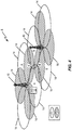
- Fig. 2 illustrates a future deployment scenario.
- a UE may have to aggregate one carrier, e.g., F1, from a network node or base station eNB A, and another, e.g., F2, from another network node or base station eNB B.
- F1 and F2 managed by eNB A and eNB B are labeled A and B, respectively.
- the UE may be connected to a primary cell, a "master" cell, handled by one base station, and simultaneously to between one and four secondary cells, "assisting" cells, handled by other base station(s).
- the primary cell and secondary cell(s) are on different carriers, the UE handles aggregation in a manner similar to aggregation in the Release 11 deployment scenarios depicted in Fig. 1 .
- Fig. 2 can be understood as depicting one example of inter-node radio resource aggregation/inter-node carrier aggregation.
- a UE that is in the coverage of network node eNB A on one carrier and in the coverage of network node eNB B on another carrier may aggregate both carriers even though the cells are handled by different base stations.
- aggregation as considered in the 3GPP standards up to Release 11 would only be done within each respective base station, either eNB A or eNB B, but not both eNB A and eNB B.
- the cells on both carriers may provide macro coverage-i.e., have large cell radius.
- 3GPP TS 36.133 specifies the requirements on the maximum delay for SCell activation, from reception of the activation command until valid channel state information, CSI, is transmitted to the network.
- activation shall be completed within: 24 ms if the cell is known, which is defined as Reference Signal Received Power (RSRP) measurements having been reported to the network within the last min of 5 DRX cycles or 5 SCell measurement cycles; and 34 ms if the cell is unknown-i.e., a blind activation where the cell has not been reported within the last min 5 DRX cycles or 5 SCell measurement cycles.
- RSRP Reference Signal Received Power
- DRX denotes discontinuous reception.
- the UE shall start transmitting CSI 8 ms after having received the SCell activation command.
- CSI shall indicate out-of-range, which is indicated using CQI index 0.
- the requirements shall be met for a worst-case scenario regarding the available number of unicast subframes. For LTE FDD, the worst case is when there are two unicast subframes per 5 ms, For LTE TDD, the worst case is when there is only one unicast subframe and one special subframe per 5 ms.
- the UE can be served by two nodes, which are referred to as a "main" eNB or MeNB, and "secondary" eNB or SeNB.
- the UE is configured with a PCC from both MeNB and SeNB.
- the PCells from the MeNB and SeNB are referred to as the PCell and the PSCell, respectively.
- the PCell and PSCell typically operate independently with respect to the UE.
- the UE is also configured with one or more SCCs from each of the MeNB and SeNB.
- the corresponding secondary serving cells served by MeNB and SeNB are simply referred to as SCells.
- a UE operating in DC typically has separate transceivers, TX/RX, for each of the connections with the MeNB and SeNB. This feature allows the MeNB and SeNB to independently configure the UE with respect to one or more procedures on the PCell and the PSCell. Examples of such procedures include radio link monitoring, RLM, DRX cycles, etc.
- the UE can be configured to periodically report CQI to the base station.
- the reporting period can be: 2, 5, 10, 20, 40, 80, 160, 32, 64, and 128 ms, respectively.
- the reporting period can be: 1, 5, 10, 20, 40, 80, and 160 ms, respectively.
- 3GPP TS 36.213, clause 7.2.2 there are some restrictions on the UL/DL configuration in use.
- a typical network configuration uses a CQI reporting period in the range 5 to 40 ms.
- the CQI values that can be reported are depicted in Table 1, as presented in Fig. 3 . More particularly, the table depicts 4-bit CQI values according to 3GPP TS 36.213, clause 7.2.3. Note that according to its conventional meaning, a CQI index value of 0 indicates to the eNB that the UE is out of radio coverage. CQI reporting may be aperiodic, in which case the UE reports CQI to the eNB responsive to indications in the Downlink Control Information or DCI.
- Event-triggered reporting also may be used.
- a UE may be configured with events. The triggering of a given event causes the UE to take some action. For example, a certain event trigger causes the UE to report measured signal strength and signal interference values for detected cells.
- event A1 in which the serving cell becomes better than threshold
- event A2 in which the serving cell becomes worse than threshold
- event A3, in which a neighbor cell becomes better than the PCell by some defined offset
- event A4 in which a neighbor cell becomes better than some threshold
- event A5, in which the PCell becomes worse than a threshold1 and a neighbor cell becomes better than a threshold2
- event A6, in which a neighbor cell becomes better than an SCell by some defined offset
- event B1 in which an inter RAT neighbor cell becomes better than some threshold
- event B2 in which a PCell becomes worse than a threshold1 and an inter RAT neighbor cell becomes better than a threshold2.
- the eNB likely will have to be more conservative than necessary.
- the radio propagation delay may change rapidly.
- the radio propagation delay changes rapidly and by a potentially significant amount whenever the line-of-sight is lost and the UE receives only reflected radio waves.
- a UE that has been activated while within the range of supported time differences between the PCell and an SCell may experience a time difference outside that range, particularly if the SCell has been activated close to the border with respect to propagation delays between PCell and SCell.
- the behavior of a UE that suddenly falls outside of its supported range of time differences is undefined.
- 3GPP R2-141849 discloses that MeNB and SeNB could be unsynchronized in dual connectivity and their SFN timing could be different.
- 3GPP R4-141623 discloses maximum received timing difference from MeNB and SeNB for synchronized dual connectivity network.
- 3GPP R2-133992 "Handling of activation-deactivation in dual connectivity" discloses activation/deactivation of serving cells with SeNB to be controlled by the SeNB or at least one serving cell of the SCG always to be activated upon configuration.
- a wireless device operating in a wireless communication network determines the difference in signal arrival times with respect to first and second cells, and the device and/or the involved wireless communication network uses the difference to control one or more aspects of Carrier Aggregation, CA, operation for the wireless device.
- CA Carrier Aggregation
- there may be a maximum timing difference defined for the wireless device e.g., as a function of its inherent capabilities, and the wireless device may evaluate the timing difference of a second cell that is a candidate of aggregation into its CA configuration, or that may be a candidate for activation as a serving cell within a CA configuration, with respect to a first cell that is already in use as a serving cell for the wireless device.
- a method at a wireless device configured for operation in a wireless communication network that supports Carrier Aggregation, CA includes measuring a difference in signal arrival times at the device for a second cell with respect to a first cell that is, or is associated with, a serving cell of the device. The method further includes comparing the difference to a configured value representing a maximum time difference permitted at the device for aggregating the second cell as another serving cell of the device, sending feedback to a network node in the network, at least on a conditional basis, indicating a result of the comparison.
- a method of CA operation at a wireless device operating in a wireless communication network that supports CA includes determining a difference in signal arrival times for a second serving cell in the CA configuration with respect to a first serving cell in the CA configuration, and detecting whether the difference is in-range or out-of-range with respect to a maximum time difference permitted for the wireless device.
- the method further includes autonomously performing at least one of: for the case where the second serving cell is in an activated state in the context of the CA configuration, deactivating the second serving cell responsive to determining that the difference is out-of-range; and for the case where the second serving cell is in a deactivated state in the context of the CA configuration, activating the second serving cell responsive to determining that the difference is in-range.
- a wireless device is configured for operation in a wireless communication network that supports CA and includes a communication interface and a processing circuit operatively associated with the communication interface.
- the communication interface is configured to receive signals from first and second cells in the network, where at least the first cell is or is associated with a serving cell of the device.
- the processing circuit is configured to measure a difference in signal arrival times at the device for a second cell with respect to the first cell, compare the difference to a configured value representing a maximum time difference permitted at the device for aggregating the second cell as a serving cell for the device, and, at least on a conditional basis, send feedback to the network indicating a result of the comparison.
- a method at a network node configured for operation in a wireless communication network that supports CA includes receiving feedback from a wireless device for a second cell.
- the feedback is dependent on whether a difference at the device in signal arrival times for the second cell with respect to a first cell is in-range or out-of-range with respect to a maximum time difference permitted for the device.
- the first cell is, or is associated with, a serving cell or the wireless device and the method includes controlling at least one of aggregation and activation of the second cell as a serving cell of the device, in response to the feedback.
- a network node is configured for operation in a wireless communication network that supports CA comprises communication interface configured to receive feedback from a wireless device for a second cell, where the feedback depends on whether a difference at the device in signal arrival times for the second cell with respect to a first cell is in-range or out-of-range with respect to a maximum time difference permitted for the device.
- the first cell is, or is associated with, a serving cell for the wireless device.
- the network node further includes a processing circuit that is operatively associated with the communication interface and is configured to control at least one of aggregation and activation of the second cell as a serving cell of the device, in response to the feedback.
- a method at a wireless device configured for operation in a wireless communication network that supports CA includes measuring a difference in signal arrival times at the device for a second cell with respect to a first cell and performing at least one of: controlling whether or not the second cell is active as a serving cell in a CA configuration of the device in dependence on whether or not the difference in signal arrival times exceeds a maximum time difference permitted at the device; and indicating the difference in signal arrival times to the network, for use by the network in controlling at least one of aggregation and activation of the second cell as a serving cell for the device.
- a wireless device is configured for operation in a wireless communication network that supports CA and includes a communication interface configured to receive signals from the network and to send signals to the network, and further includes a processing circuit that is operatively associated with the communication interface.
- the processing circuit is configured to measure a difference in signal arrival times at the device for a second cell with respect to a first cell, and perform at least one of: control whether or not the second cell is active as a serving cell in a CA configuration of the device in dependence on whether or not the difference in signal arrival times exceeds a maximum time difference permitted at the device; and indicate the difference in signal arrival times to the network, for use by the network in controlling at least one of aggregation and activation of the second cell as a serving cell for the device.
- a method at a network node configured for operation in a wireless communication network that supports CA includes receiving an indicated difference in signal arrival times from a wireless device, for a second cell with respect to a first cell. The method further includes controlling at least one of aggregation and activation of the second cell as a serving cell in a CA configuration of the device, in dependence on the indicated difference in signal arrival times.
- a network node is configured for operation in a wireless communication network that supports CA and includes a communication interface that is configured to receive, directly or indirectly, indications from a device operating in the network of differences of signal arrival times at the device, for a second cell with respect to a first cell.
- the network node further includes a processing circuit that is operatively associated with the communication interface and is configured to control at least one of aggregation and activation of the second cell as a serving cell in a CA configuration of the device, in dependence on the indications of the differences in signal arrival times.
- a UE as termed herein can be any type of wireless apparatus capable of communicating with a communication network node and/or with another wireless apparatus via radio signals.
- the UE may be a target device (where "target” refers to a given device being positioned), a Device-to-Device, D2D, UE, a Machine Type Communications, MTC, UE or UE capable of Machine-to-Machine, M2M, communications, a sensor or other embedded device equipped with a wireless communication interface, a tablet, mobile terminal, smart phone, laptop, network adaptor, USB dongles, modems, Customer Premises Equipment, CPE, etc.
- radio network node such as "radio network node”, “network node”, or “NW node”.
- all such references should be understood as broadly referring to any one of a variety or network node types, such as a base station, a radio base station, a base transceiver station, a base station controller, a network controller, an evolved Node B, eNB, a Node B, a Main eNB, MeNB, in a dual-connectivity configuration, a Secondary eNB, SeNB, in a dual-connectivity mode, a relay node, an access point, a radio access point, a Remote Radio Unit or RRU, or a Remote Radio Head or RRH, etc.
- PCell is used and unless explicitly restricted or a particular intended meaning is clear from the context, this term should be broadly understood to cover any type of primary cell, such as a primary cell in a simple primary/secondary cell case, or a Primary Secondary Cell, PSCell, in a Dual Connectivity, DC, scenario.
- time difference of arrival is sometimes shortened in this discussion to "time difference”.
- any references herein to "timing difference” or “timing difference between cells” should be understood as referring to the difference in signal arrival times at a wireless device, as between the signals from the noted cells.
- a UE or other wireless device experiences such timing differences as between a PCell and a SCell, as between a PCell and a PSCell, and as between respective SCells.
- Fig. 4 depicts an example wireless communication network 8 that includes a number of network nodes 10, which here are configured as base stations that provide communication services to one or more UEs or other wireless devices 12, where one wireless device 12, denoted as "WD 12" in the diagram, is illustrated for ease of discussion.
- the network nodes 10 each provide radio coverage in a number of cells 14, includes cells 14 that operate on a first carrier frequency F1, and cells 14 that operate on a second carrier frequency F2.
- the wireless device 12 and one or more of the network nodes 10 are configured according to one or more embodiments of the device-side and network-side teachings presented herein, respectively.
- Fig. 5 illustrates example embodiments of a network node 10 and a wireless device 12.
- the network node 10 comprises a network base station, such as an eNB in a Long Term Evolution, LTE, network.
- the example network node 10 depicted in Fig. 5 includes a communication interface 20, which may comprise more than one communication interface.
- the communication interface 20 includes radiofrequency transceiver circuitry-i.e., receiver and transmitter circuitry-for transmitting signals to wireless devices 12 in one or more cells supported by the network node 10, and for receiving signals from such devices 12.
- the communication interface 20 may further comprise an inter-base station signaling interface and/or a Core-Network interface to one or more nodes in a Core Network associated with the Radio Access Network portion of the wireless network in which the node is configured to operate.
- the network node 10 further includes a processing circuit 22 that is configured to carry out any or all of the network-side method(s) taught herein.
- the processing circuit 22 may comprise or be included in a number of digital processing circuits 24.
- Non-limiting examples of such circuitry include a microprocessor, Digital Signal Processor, Application Specific Integrated Circuit, ASIC, Field Programmable Gate Array, FGPA, and/or other digital processing circuit(s).
- Such circuitry may be configured as fixed circuitry, or as programmed circuitry, or as a mix of fixed and programmed circuitry.
- the processing circuit 22 is configured to carry out the network-node processing as taught herein based at least in part on the execution of a computer program product 26 stored in a computer-readable medium 28, which may also store configuration information or data.
- a computer program product 28 comprises computer program instructions and that the execution of those program instructions by the digital processing circuits 24 specially adapt the digital processing circuits 24 to carry out the network-side processing operations taught herein, including implementation or execution of the disclosed algorithms.
- the computer-readable medium 28 may actually comprise media, e.g., more than one memory device and/or more than one type of memory, such as EEPROM, FLASH and/or Solid State Disk.
- the computer-readable medium 28 also may include working memory, such as SRAM.
- the computer-readable medium 28 stores the computer program 26 in question in a non-transitory state, i.e., the computer-readable medium 28 provides for storage of at least some persistence. Note, however, that non-transitory storage does not necessarily mean permanent or unchanging storage, but the term does exclude merely propagating signals.
- the wireless device 12 includes a communication interface 30, which comprises or includes radiofrequency transceiver circuitry-i.e., receiver and transmitter circuitry-for transmitting signals to and receiving signals from one or more nodes in a wireless communication network 8 in which the device 12 is configured to operate.
- the network node 10 is a base station and the device 12 is configured to communicate with the network node 10 according to the defined air interface protocols, structure, timing, etc.
- the device 12 further includes a processing circuit 32 that is configured to carry out any or all of the device-side method(s) taught herein.
- the processing circuit 32 may comprise or be included in a number of digital processing circuits 34.
- Non-limiting examples of such circuitry include a microprocessor, Digital Signal Processor, Application Specific Integrated Circuit, ASIC, Field Programmable Gate Array (FGPA), and/or other digital processing circuit(s).
- Such circuitry may be configured as fixed circuitry, or as programmed circuitry, or as a mix of fixed and programmed circuitry.
- the processing circuit 32 is configured to carry out the device-side processing as taught herein based at least in part on the execution of a computer program product 36 stored in a computer-readable medium 38, which may also store configuration information or data.
- a computer program product 38 comprises computer program instructions and that the execution of those program instructions by the digital processing circuits 34 specially adapt the digital processing circuits 34 to carry out the device-side processing operations taught herein, including execution of the disclosed algorithms.
- the computer-readable medium 38 may actually comprise media, e.g., more than one memory device and/or more than one type of memory, such as EEPROM, FLASH and/or Solid State Disk.
- the computer-readable medium 38 also may include working memory, such as SRAM.
- the computer-readable medium 38 stores the computer program 36 in question in a non-transitory state, i.e., the computer-readable medium 28 provides for storage of at least some persistence. Note, however, that non-transitory storage does not necessarily mean permanent or unchanging storage, but the term does exclude merely propagating signals.
- the communication interface 30 of the device 12 is configured to receive signals from first and second cells 14 in the network 8, wherein at least the first cell 14 is or is associated with a serving cell 14 of the device 12.
- the processing circuit 32 of the device 12 is operatively associated with the communication interface 30 and is configured to measure a difference in signal arrival times at the device 12 for the second cell 14 with respect to the first cell 14, and to compare the difference to a configured value representing a maximum time difference permitted at the device 12 for aggregating the second cell 14 as a serving cell for the device 12. Further, the processing circuit 32 is configured to, at least on a conditional basis, send feedback to the network 8 indicating a result of the comparison.
- the first and second cells 14 are configured as serving cells 14 in a CA configuration of the device 12 and both cells 14 are activated for serving the device 12.
- the processing circuit 32 of the device 12 is configured to send the feedback to the network 8 as an out-of-range indication for the second cell 14, in response to detecting the difference going out-of-range with respect to the maximum time difference.
- the first and second cells 14 are configured as serving cells 14 in a CA configuration of the device 12.
- the processing circuit 32 of the device 12 is configured to send, as at least part of the feedback, periodic indications of whether the difference is in-range or out-of-range with respect to the maximum time difference.
- the first cell 14 is configured as a serving cell 14 in a CA configuration of the device 12, and the second cell 14 is a candidate for aggregating in the CA configuration.
- the processing circuit 32 of the device 12 is configured to send, as at least part of the feedback it sends to the network 8, an indication responsive to detecting the difference coming in-range with respect to the maximum time difference.
- the configured value in an example case is signaled to the device 12 by the network 8.
- the configured value is preconfigured in the device 12, e.g., it is provisioned or otherwise stored in the configuration data held in the computer-readable medium 38.
- the device 12 accommodates both possibilities, such as where it uses a preconfigured value from its storage, unless the network 8 sends a value to use. It may be that priority is given to network-signaled values, e.g., a network-signaled value overrides the preconfigured value, but such overriding may be constrained.
- the preconfigured value stored in the device 12 in one or more embodiments represents a maximum arrival time difference supported by the device 12 for cell aggregation.
- the processing circuit 32 is configured to send the feedback to the network 8 as an out-of-range indication for the second cell 14, in response to determining from the comparison that the difference exceeds the maximum time difference supported by the wireless device 12 for cell aggregation.
- the processing circuit 32 may be configured to send the out-of-range indication implicitly, by transmitting a certain value or signal according to a defined pattern that is recognized by the network 8 as the out-of-range indication.
- the certain value or signal has a signaling purpose independent from use as an indicator of the out-of-range condition.
- the certain value or signal is "overloaded" by the device 12, which may continue to use it for its intended purpose, but which also uses it to implicitly signal the out-of-range condition.
- the processing circuit 32 is configured to transmit the certain value or signal as one of: a minimum Channel Quality Indicator, CQI, index value according to the defined pattern; an alternating pattern of minimum and maximum CQI index values; Negative Acknowledgements or NACKs according to the defined pattern; a defined reference signal sequence; and one or more random access preambles according to the defined pattern.
- CQI Channel Quality Indicator
- the first and second cells 14 comprise one of: a Primary Cell, PCell, and a Secondary Cell, SCell, in a CA configuration of the wireless device 12; two Secondary Cells, SCells, in the CA configuration; or a PCell from a main base station in a dual-connectivity configuration for the wireless device 12, and a Primary Secondary Cell, PSCell, from a secondary base station in the dual-connectivity configuration.
- the wireless device 12 is configured for operation in a wireless communication network 8 that supports CA
- the communication interface 30 of the device 12 is configured to receive signals from the network 8 and to send signals to the network 8
- the processing circuit 32 of the device 12 is configured to measure a difference in signal arrival times at the device 12 for a second cell 14 with respect to a first cell 14.
- the processing circuit 32 is configured to perform at least one of: control whether or not the second cell 14 is active as a serving cell 14 in a CA configuration of the device 12, in dependence on whether or not the difference in signal arrival times exceeds a maximum time difference permitted at the device 12; and indicate the difference in signal arrival times to the network 8, for use by the network 8 in controlling at least one of aggregation and activation of the second cell 14 as a serving cell 14 for the device 12.
- a base station or other type of network node 10 is configured for operation in a wireless communication network 8 that supports CA, and the communication interface 20 of the network node 10 is configured to receive feedback from a wireless device 12 for a second cell 14.
- the feedback is dependent on whether a difference at the device 12 in signal arrival times for the second cell 14 with respect to a first cell 14 is in-range or out-of-range with respect to a maximum time difference permitted for the device 12.
- the first cell 14 is, or is associated with, a serving cell 14 for the wireless device 12, and the processing circuit 22 of the network node is configured to control at least one of aggregation and activation of the second cell 14 as a serving cell 14 of the device 12, in response to the feedback.
- the first and second cells 14 are both configured as serving cells 14 in a CA configuration of the device 12, and the processing circuit 22 of the network node 10 is configured to deactivate the second cell 14 with respect to serving the device 12, in response to the feedback indicating the out-of-range condition for the second cell 14.
- the device 12 is configured to provide the feedback as event-driven feedback sent on an event-driven basis and, and the processing circuit 22 is configured to toggle activation or deactivation of the second cell 14 with respect to serving the device 12, responsive to receiving the event-driven feedback from the device 12.
- the device 12 is configured to provide the feedback as periodic feedback.
- the processing circuit 22 is configured to toggle activation or deactivation of the second cell 14 with respect to serving the device 12, responsive to receiving the periodic feedback from the device 12.
- the network node 10 may respond to periodic feedback and to event-driven feedback. For example, in a first scenario or under first conditions, a given device 12 provides periodic feedback, while in a second scenario or under second conditions, a given device 12 provides event-driven feedback. Further, a given device 12 may provide both periodic feedback and event-driven feedback, or one device 12 may provide periodic feedback while another device 12 provides event-driven feedback.
- the first cell 14 is PCell in a CA configuration of the device 12 and the second cell 14 is one of one or SCells included in the CA configuration
- the processing circuit 22 is configured to receive periodic mobility reports from the device 12. Each report indicates a difference in signal arrival times at the device 12 for one or more of the SCells with respect to the PCell and, for each of one or more reports, the processing circuit 22 is configured to: determine a location of the device 12 from the mobility report; associate the differences in arrival times included in the mobility report with the location of the device 12; and store the location and the associated differences in a database 29.
- the database 29 may be stored by the network node 10 in the computer-readable medium 28, such as is shown in the non-limiting example of Fig. 5 , or the database 29 may reside elsewhere and be updated by the processing circuit 22 via signaling.
- the one or more processing circuits 24 of the network node are configured to, over time, receive periodic mobility reports from multiple devices 12 operating with CA configurations involving multiple cells 14 of the network 8, and accumulate location information and associated signal arrival time differences in the database 29.
- the one or more processing circuits 24, e.g., via the processing circuit 22, are further configured to derive coverage information for cell aggregation for the multiple cells 14 in the network 8, from the accumulated location information and associated signal arrival time differences in the database 29, and use the coverage information to inform carrier aggregation decisions made by the network 8 for given devices 12 operating within areas of the network 8 corresponding to the coverage information.
- the one or more processing circuits 24 are configured to use the coverage information at least in part to make CA configuration decisions for a given device 12 currently operating in an area of the network 8 corresponding to the coverage information. Additionally, or alternatively, the one or more processing circuits 24 are configured to use the coverage information derived from the database 29 to better judge where cells 14 can be aggregated, and to thereby obviate or reduce the need to have devices 12 operating in the areas of the network 8 corresponding to the database 29 to send indications of actual cell-to-cell arrival time differences. Among other advantages, this obviation reduces signaling overhead.
- the one or more processing circuits 24 are configured to share the coverage information with one or more other network nodes 10.
- the network node 10 is an eNB or other base station
- the network node 10 shares the coverage information with neighboring base stations.
- the network node 10 is also configured to receive coverage information from another network node 10, and to use the received coverage information to inform carrier aggregation decisions made by the network node 10.
- a first network node 10 may share coverage information with a second network node 10, for use by the second network node 10 and/or the first network node 10 may use coverage information shared with it by the second network node 10.
- a network node 10 as contemplated herein is configured for operation in a wireless communication network 8 that supports CA and it includes a communication interface 20 that is configured to receive, directly or indirectly, indications from a device 12 operating in the network 8 of differences of signal arrival times at the device 12, for a second cell 14 with respect to a first cell 14.
- the contemplated network node 10 which may be but not necessarily is a base station or other radio network node, includes a processing circuit 22 that is operatively associated with the communication interface 30 and configured to control at least one of aggregation and activation of the second cell 14 as a serving cell 14 in a CA configuration of the device 12, in dependence on the indications of the differences in signal arrival times.
- Fig. 6 illustrates a method 600 at a wireless device 12 configured for operation in a wireless communication network 8 that supports CA. It will be appreciated that the method 600 may be implemented via the circuit arrangement depicted in Fig. 5 for the wireless device 12, e.g., by execution of computer program instructions from the computer program 36. However, the method 600 is not limited to that circuit arrangement, and it should be understood that one or more steps of the method may be performed in an order other than that suggested by the illustration and/or may be performed in parallel or along with other processing ongoing at the device 12.
- the method 600 includes measuring (Block 602) a difference in signal arrival times at the device 12 for a second cell 14 with respect to a first cell 14 that is, or is associated with, a serving cell 14 of the device 12.
- the method 600 further includes comparing (Block 604) the difference to a configured value representing a maximum time difference permitted at the device 12 for aggregating the second cell 14 as another serving cell 14 of the device 12, and sending (Block 606) feedback to a network node 10 in the network 8, at least on a conditional basis, indicating a result of the comparison.
- the "maximum time difference" here, for example, is the maximum value as dictated by the capabilities of the device 12, or it may be the maximum as signaled by the network 8.
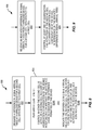
- Fig. 7 illustrates a method 700 at a network node 10 configured for operation in a wireless communication network 8 that supports CA. It will be appreciated that the method 700 may be implemented via the circuit arrangement depicted in Fig. 5 for the network node 10, e.g., by execution of computer program instructions from the computer program 26. However, the method 700 is not limited to that circuit arrangement, and it should be understood that one or more steps of the method may be performed in an order other than that suggested by the illustration and/or may be performed in parallel or along with other processing ongoing at the network node 10.
- the method 700 includes receiving (Block 702) feedback from a wireless device 12 for a second cell 14, where the feedback is dependent on whether a difference at the device 12 in signal arrival times for the second cell 14 with respect to a first cell 14 is in-range or out-of-range with respect to a maximum time difference permitted for the device 12.
- the first cell 14 is, or is associated with, a serving cell 14 for the wireless device 12, and the method 700 correspondingly includes the network node 10 controlling (Block 704) at least one of aggregation and activation of the second cell 14 as a serving cell 14 of the device 12, in response to the feedback.
- Fig. 8 illustrates another example method 800 performed by a wireless device 12 in one or more embodiments.
- the wireless device 12 is configured for operation in a wireless communication network 8 that supports CA.
- the method 800 includes measuring (Block 802) a difference in signal arrival times at the device 12 for a second cell 14 with respect to a first cell 14, performing (Block 804) at least one of: controlling (Block 804A) whether or not the second cell 14 is active as a serving cell 14 in a CA configuration of the device 12 in dependence on whether or not the difference in signal arrival times exceeds a maximum time difference permitted at the device 12; and indicating (Block 804B) the difference in signal arrival times to the network 8, for use by the network 8 in controlling at least one of aggregation and activation of the second cell 14 as a serving cell 14 for the device 12.
- the maximum time difference represents, for example, a maximum time difference that is supported by the device 12 or that is configured by the network 8 as between the signal arrival times of respective active serving cells 14 of the device 12.
- Indicating the difference in signal arrival times to the network 8 comprises, in at least one embodiment, indicating the difference in signal arrival times as a quantized value.
- indicating the difference in signal arrival times as a quantized value comprises the wireless device 12 sending an in-range or out-of-range indication to the network 8 on at least a conditional basis. This can be understood as signaling a go or no-go, or good or bad indication, rather than signaling the actual arrival time difference.
- the processing circuit 32 of the wireless device 12 is configured to implement the method 800.
- the processing circuit 32 is configured to measure the difference in signal arrival times at the device 12 for a second cell 14 with respect to a first cell 14, and perform the operations of Block 804A and/or Block 804B.
- Fig. 9 illustrates another example method 900 at a network node 10, according to one or more embodiments contemplated herein.
- the network node 10 is configured for operation in a wireless communication network 8 that supports CA
- the method 900 includes receiving (Block 902) an indicated difference in signal arrival times from a wireless device 12, for a second cell 14 with respect to a first cell.
- the method 900 further includes controlling (Block 904) at least one of aggregation and activation of the second cell 14 as a serving cell 14 in a CA configuration of the device 12, in dependence on the indicated difference in signal arrival times.
- controlling (Block 904) at least one of the aggregation and the activation of the second cell 14 comprises controlling the activation of the second cell 14, responsive to determining from the indicated difference in signal arrival times whether or not the second cell 14 is in-range or out-of-range with respect to a maximum time difference permitted for the device 12.
- controlling (Block 904) at least one of the aggregation and activation of the second cell 14 comprises determining from the indicated difference in signal arrival times for the second cell 14 as to whether the difference in signal arrival times for the second cell 14 is in-range or out-of-range with respect to a maximum time difference permitted at the device 12. For a case where the second cell 14 is currently activated as a serving cell 14 for the device 12, the controlling of Block 904 comprises deactivating the second cell 14, responsive to determining that the second cell 14 is out-of-range.
- determining whether the second cell 14 is in-range or out-of-range comprises receiving a measurement value from the device 12 as the indicated difference in signal arrival times for the second cell 14, and comparing the measurement value to the maximum time difference permitted at the device 12.
- the maximum time difference may be signaled by the device 12, based on its capability, or may be set by the network 8, based on a determined value or based on a default or assumed value.
- receiving (Block 902) the indicated difference in signal arrival times for the second cell 14 comprises detecting that a signal or value sent from the device 12 has a characteristic pattern that is indicative of a quality or condition of the difference in signal arrival times for the second cell 14 as measured by the device 12.
- the device 12 may send CQI values in a distinctive pattern, or send NACKs in a distinctive pattern, etc.
- the network node 10 illustrated in Fig. 5 may be configured to implement the method 900, although the method 900 may be performed by other circuit arrangements.
- the processing circuit 22 is configured to control at least one of aggregation and activation of a second cell 14 as a serving cell 14 in a CA configuration of a wireless device 12, in dependence on the indications of the differences in signal arrival times between a first cell and the second cell.
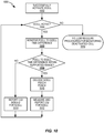
- Fig. 10 illustrates a particular example embodiment of a method 1000 of a UE or other wireless device 12 monitoring PCell-to-SCell timing and reporting CQI index 0 when the SCell goes out-of-range with respect to a maximum time difference signaled to the device 12 or otherwise known to the device 12. More broadly, the method 1000 can be understood as a wireless device 12 monitoring PCell-to-SCell timing and reporting pre-defined feedback signal or pre-defined pattern of feedback signals, e.g. CQI index 0 or consecutive CQI 0 over certain subframes, when the signal arrival time difference between the PCell and the SCell goes out-of-range.
- pre-defined feedback signal or pre-defined pattern of feedback signals e.g. CQI index 0 or consecutive CQI 0 over certain subframes
- the method 1000 "begins" with the assumption that the wireless device 12 has been requested to activate a SCell and has successfully done so (Block 1002). As long as the SCell still is active (YES from Block 1004), the wireless device 12 monitors the time difference between PCell and SCell (Block 1006). As long as the timing difference is within the defined maximum time difference (YES from Block 1008), the wireless device 12 continues decoding Physical Downlink Control Channel, PDDCH, / Physical Downlink Shared Channel, PDSCH, transmissions to it (Block 1010), and correspondingly reporting non-zero CQI values (Block 1012) (in-range condition).
- PDDCH Physical Downlink Control Channel
- PDSCH Physical Downlink Shared Channel
- the wireless device 12 reports a CQI index value of zero for the SCell (Block 1014).
- the maximum time difference is at least as large as that needed to comply with any controlling standards, e.g., at least the 30.26 ⁇ s minimum allowed by the 3GPP standard for PCell-to-SCell signal arrival time differences.
- the maximum time difference may be larger than any applicable minimum, e.g., it may be set according to the actual capabilities of the wireless device 12, or the network 8 may set it to a default value or some value calculated in view of applicable network conditions.
- Block 1016 processing follows regular procedures for monitoring a deactivated cell (Block 1016).
- the SCell may be deactivated explicitly by the network 8, e.g., via Medium Access Control (MAC) signaling sent to the wireless device 12, or it may be deactivated upon expiration of a controlling timer.
- MAC Medium Access Control
- CQI index zero in the above method 1000 is a non-limiting example of using a certain value or signal as an implicit indicator to the network 8.
- CQI values are used conventionally to indicate, it is contemplated herein to send CQI 0 values for an involved cell according to a defined pattern, wherein that pattern is known to the network 8 as signifying, for example, the out-of-range condition for the cell's signal arrival times relative to the arrival times of signals from another cell.
- sending CQI 0 according to a defined pattern implicitly indicates that the signal arrival time difference between two cells exceeds a defined maximum time difference.
- Non-limiting example patterns include: consecutive CQI index 0 transmissions over N consecutive CQI reporting occasion, TTI or subframes; alternate CQI index 0 and CQI index 15-a maximum index value-over M consecutive CQI reporting occasion, TTI or subframes; consecutive NACK transmissions over N consecutive TTI or subframes or transmission occasions; a certain pre-defined sequence of reference signal, such as a Sounding Reference Signal, SRS, sequence; or a certain pattern of random access preamble sequences transmitted over N Random Access Channel, RACH, transmission occasions.
- SRS Sounding Reference Signal
- the pattern may comprise more than one preamble sequence, which could be transmitted either in consecutive RACH transmission occasions, or each sequence in the pattern could be transmitted in every Pth RACH transmission occasion.
- the preamble sequences in the pattern can be pre-defined. This scheme can be used especially when there is also an uplink SCell on which RACH is allowed, but it should be understood that the wireless device 12 could send such signaling on either the uplink PCell or uplink PSCell in a Dual Connectivity, DC, configuration.
- the parameters associated with the pattern can be pre-defined or configured by the network node 10.
- Example parameters include: the pattern sequence length N, e.g., the number of elements comprising the pattern sequence; and the inter-sequence distance in time, e.g., the pattern definition specifies that each element in the sequence is sent over every Kth TTI, such as every two TTIs or every 2 ms.
- the pattern definition may depend on a reference time, which indicates a starting time for the pattern, or enables derivation of the starting time.
- the pattern end time may also be a defined parameter.
- the pattern stop time may also be known from the start time and knowledge of the pattern length.
- the wireless device 12 when a wireless device 12 detects that the received time difference of signals between a PCell and a SCell at the wireless device 12 exceeds the permitted maximum time difference, the wireless device 12 reports a CQI index for both the PCell and the SCell in the same reporting occasion or in consecutive reports.
- the network node 10 is configured to recognize or interpret such signaling as being an indication of the out-of-range condition for the difference in signal arrival times between the involved PCell and SCell.
- This signaling behavior may be carried out by the wireless device 12 for as long as the SCell still is active and out of range, where "range” here denotes the maximum supported difference in signal arrival times between the SCell and, e.g., the PCell.
- range here denotes the maximum supported difference in signal arrival times between the SCell and, e.g., the PCell.
- the wireless device 12 in one or more embodiments terminates its uplink transmissions with respect to the SCell. If the received time difference between the PCell and the SCell falls back within the maximum time difference, or a lower value that, e.g., provides hysteresis for the in-range/out-of-range condition detection, the wireless device 12 in this embodiment resumes normal transmission behavior. That is, it transmits CQI indexes corresponding to actual SCell quality. This behavior enables the network node 10 to recognize that the received timing between the PCell and the SCell has fallen back to an acceptable difference.
- the wireless device 12 when cross-carrier scheduling is used, receives control information, including PDSCH allocations, for both the PCell and the SCell, via PDCCH transmissions in the PCell. Thus, the wireless device 12 does not monitor the PDCCH as seen in Block 1010 in Fig. 10 . As an alternative, because the wireless device 12 can receive PDSCH allocations for the SCell via PDCCH transmissions to it in the PCell, the wireless device 12 may send NACKs in response to all allocations it receives for the SCell.
- Fig. 11 illustrates an example method 1100 of a network node 10 monitoring and acting upon CQI reporting from a UE or other wireless device 12.
- the network node 10 is, for example, a base station and has successfully had the wireless device 10 to activate a SCell in a CA configuration, and has configured periodic CQI reporting by the wireless device 12 (Block 1102).
- the network node 10 thus receives CQI reports from the wireless device 12 (Block 1104), and checks whether the CQI reported by the wireless device 12 indicates that the SCell is within range, with respect to the permissible maximum time difference in signal arrival times (Block 1106).
- the network node 10 interprets non-zero CQI values from the wireless device 12 as indicating both channel conditions and the in-range condition for the SCell, and considers the SCell as being available for scheduling use with respect to the wireless device 12 (YES from Block 1106 and Block 1108). On the other hand, if the wireless device reports CQI 0 for the SCell (NO from Block 1106), the network node 10 deactivates the SCell with respect to the wireless device 12 (Block 1110).
- the wireless device 12 when SCell control information, including allocations, are transmitted via PCell control signaling to the wireless device 12, the wireless device 12 may be configured to NACK all allocations received for the SCell, when the SCell is in the out-of-range condition.
- the network node 10 may be configured to deduce that the SCell is out-of-range if a certain number of consecutive NACKs are received from the wireless device 12 in response to allocations sent in the SCell.
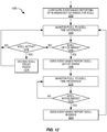
- Fig. 12 illustrates an example method 1200 of processing at a UE or other wireless device 12, which uses event-based reporting of the in-range/out-of-range condition for a SCell.
- the wireless device 12 is configured to use event-based reporting (Block 1202), and in operation it monitors the difference in signal arrival times between the SCell and the PCell (Block 1204) and determines from that monitoring whether the SCell is out-of-range (Block 1206). If so (YES from Block 1206), the wireless device 12 sends an event-based report to the network node 10, indicating that the SCell is out of range (Block 1208). The wireless device 12 then monitors to see whether the SCell comes back into range (Block 1210 and Block 1212). If so (YES from Block 1212), the wireless device 12 sends an event-based report to the network node 10, indicating that the SCell has come back into range (Block 1214).
- the wireless device 12 checks whether the SCell is an active cell in its CA configuration (Block 1216). If so, it decodes PDCCH and PDSCH for the SCell (Block 1218), otherwise it returns to monitor the difference in signal arrival times in Block 1204.
- Fig. 12 may be understood as adding new defined "events" for reporting by a wireless device 12, e.g., new events in addition to the existing ones defined in 3GPP TS 36.331.
- new measurements may be defined in 3GPP TS 36.213 and 36.133, for these newly specified events.
- the method 1200 thus stands as a non-limiting example of event-based reporting, whereby a wireless device 12 sends reports to the network 8, in response to detecting that an SCell aggregated for CA operation with respect to the wireless device 12 has gone out-of-range, or has come back into range.
- the SCell may or may not be active in the CA configuration and this event-based reporting can be used to make activation decisions with respect to an inactive SCell and/or to make scheduling decisions-on the network side-and decoding decisions-on the device side with respect to an active SCell that goes out of range.
- the contemplated event-based reporting is useful for a number of functions within the overall network 8.
- the monitoring and event-based reporting can be useful for ad hoc-approaches to inter-node radio resource aggregation in complex network deployment scenarios.
- the wireless device 12, for example, can tell the network 8 which cells are suitable for aggregation, and the network 8 can then decide which neighboring base stations to use for providing SCells or assisting cells, for the wireless device 12.
- a UE or other wireless device 12 that supports arrival time differences between cells 14 that are larger than the standardized or predefined maximum time difference can operate at the "aggregation border" defined by the standardized maximum time difference, e.g., ⁇ 30.26 ⁇ s for the 3GPP standard.
- the controlling network node 10 can aggregate an SCell into the CA configuration of the UE even when the SCell is already at the aggregation border, and then rely on the UE to alert the network if the arrival time difference for that SCell exceeds the actual capabilities of the UE.
- This behavior allows, for example, much more flexible cell aggregation and exploits the fact that at least some UEs may be capable of supporting arrival time differences greater than the standardized maximum difference assumed for all network-compatible devices, e.g., a given UE may be capable of supporting arrival time differences of as much as ⁇ 35 ⁇ s instead of ⁇ 30.26 ⁇ s.
- a UE or other wireless device 12 provides an affirmative indication to the network when the difference in signal arrival times for a given cell 14 with respect to another given cell 14 exceeds a maximum time difference permitted at the device 12 which may be in excess of the default or standardized maximum time difference. This behavior obviates the need for the network's overly conservative approaches to controlling cell aggregation that are intended to avoid any violation of the standardized maximum time difference.
- a UE or other wireless device 12 shall indicate to a network node 10, e.g. eNB, MeNB, SeNB, base station etc., that the time difference of arrival of signals, which can be denoted as ⁇ , from the PCell to SCell, or between a PSCell and a SCell, or between a PSCell and a PCell in a DC configuration, or more generally as between any two serving cells, is out-of-range or in-range.
- the network node 10 can avoid scheduling the wireless device 12 with respect to the out-of-range cell 14 and/or can deactivate the concerned cell 14, such as responsive to ⁇ exceeding the range, e.g., going outside ⁇ 30.26 ⁇ s.
- Fig. 13 illustrates a periodic reporting method 1300 at a UE or other wireless device 12, where the wireless device 12 is configured to perform periodic reporting of PCell-to-SCell time differences, e.g., for one or more SCells that are aggregated in a CA configuration of the wireless device 12, or that are prospective candidates for such aggregation.
- the method 1300 assumes that new measurement reporting is introduced in 3GPP TS 36.213, 36.331 and 36.133.
- the wireless device 12 is configured with periodic reporting of PCell-to-SCell signal arrival time differences (Block 1302), and the wireless device 12 correspondingly monitors the time difference (Block 1304), and reports it to the network 8 periodically (Blocks 1306 and 1308).
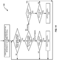
- Fig. 14 illustrates a network-side method 1400 implemented at an example network node 10, e.g., at an eNB in a LTE embodiment of the network 8.
- the method 1400 involves configuring and acting on event-based reporting of in-range and out-of-range conditions for a second cell with respect to a first cell e.g., configuring the event-based reporting whereby a wireless device 12 reports when the signal arrival time difference between a second cell with respect to a first cell goes out of range or comes back into range.
- the method 1400 includes configuring the UE or other wireless device 12 to for event-based reporting (Block 1402), determining whether an event-based report has been received from the wireless device 12 (Block 1404), and, if so, determining whether the report indicates that the second cell, here a SCell, is out of range (Block 1406). If so, processing continues with determining whether the SCell is active in a CA configuration with respect to the wireless device 12 (Block 1408) and, if so, deactivating the SCell (Block 1410). If the SCell is reported as being in range (NO from Block 1406), processing continues with determining whether the SCell is active (Block 1412). If not, processing continues with checking whether there is data to be transmitted for the wireless device (Block 1414) and, if so, activating the SCell for use in transmitting to the wireless device 12 (Block 1416).
- Such processing is useful, for example, for ad hoc-approach to inter-node radio resource aggregation in complex network deployments.
- the involved wireless device 12 tells the network 8 which cells 14 are suitable for aggregation, and the network 8 can then decide which neighboring base stations to use for providing SCells or assisting cells.
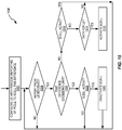
- Blocks 1502-1516 (even) of Fig. 15 illustrates similar processing at the network side, e.g., for a network node 10, but the overall method 1500 is directed to the example of configuring periodic reporting at a target UE or other wireless device 12, and receiving periodic reports relating to the difference in signal arrival times for a second cell at the wireless device 12 with respect to a first cell (Blocks 1502 and 1504).
- the network node 10 determines from a report or reports as to whether the difference in signal arrival times exceeds a defined limit (Block 1506). If so, the network node 10 determines whether the second cell, here a SCell, is active in a CA configuration of the wireless device 12 (Block 1508) and, if so, it deactivates the SCell (Block 1510).
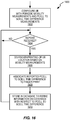
- Fig. 16 depicts a method 1600 as another example of network-side processing carried out by a suitably configured network node 10, such as an eNB or other base station.
- the method 1600 in an overall sense involves acquiring and refining information on coverage areas for PCell and SCell aggregation with respect to signal PCell-to-SCell signal arrival time differences for UEs or other wireless devices 12 operating in such coverage areas.
- a UE or other wireless device 12 is configured for periodic reporting of mobility measurements, including PCell-to-SCell signal arrival time differences (Block 1602).
- the network node 10 receives reports at the configured periodicity and, for a given received report (YES from Block 1604), the network node 10 performs "finger printing" of the location of the wireless device 12, based on the reported mobility measurements (Block 1606).
- the reported measurements include, for example, signal strength or quality measurements made by the wireless device 12 with respect to neighboring cells 14 in the network 8, and may include signal arrival time differences for any one or more cells, with respect to, e.g., a current serving cell 14 of the wireless device 12.
- the network node 10 and/or one or more other nodes in the network 8 associated the reported arrival time differences with the fingerprint information (Block 1608) and store the associations in a database, to refine the information on coverage with respect to, e.g., PCell to SCell signal arrival time differences (Block 1610).
- the network 8 can accumulate or otherwise develop a good statistical "picture" of signal arrival time differences between given cells 14 in the network 8, for any given coverage area of the network 8. Assuming that sufficient fingerprinting history is available in the database, the network node 10 can at determine the position of a given wireless device 12 based on comparing the signal arrival time differences reported by it for given cells 14 in the network 8 to the stored fingerprinting information.
- the fingerprinting may become quite accurate. Further, even where the fingerprinting is not used for reporting device position, the historical information provides a good basis on which to make cell aggregation decisions.
- the network node 10 may be configured to use the fingerprinting information to determine whether or not a given cell 14 or cells 14 should be aggregated with respect to a given wireless device 12 operating within the network 8.
- this type of fingerprinting is a valuable alternative to, or supplement for, so called "drive testing" in which measurement reports are collected from wireless devices 12 that are specifically moved or located within actual or intended coverage areas of the network 8, to collect information about coverage quality, coverage gaps, etc.
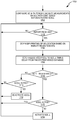
- Fig. 17 depicts yet another facet of network-side processing, such as is performed at a network node 10 in one or more embodiments contemplated herein.
- the method 1700 relates to activation and deactivation of a SCell for a given UE or other wireless device 12, based on finger-printing from mobility measurements and usage of the PCell-to-SCell arrival time difference database at issue in Fig. 16 .
- fingerprinting also may be based additionally, or alternatively, on carriers and/or Radio Access Technologies, RATs, other than the prospective Secondary Component Carriers, SCCs, associated with a Primary Component Carrier or PCC.
- RATs Radio Access Technologies
- the network node 10 configures a UE or other wireless device 12 to perform periodic mobility measurements on a SCC from a SCell that is in a CA configuration for the wireless device 12 but is currently deactivated i.e., not being used for CA transmissions to/from the device 12 (Block 1702).
- the network node 10 receives a mobility measurement or mobility report from the wireless device 12 (YES from Block 1704), and performs fingerprinting of the location based on the reported mobility measurements (Block 1706). In other words, the network node 10 compares the mobility measurements, or values derived therefrom, to corresponding parameters collected in the database, to look up the statistical or collected PCell-to-SCell signal arrival time differences (Block 1708), and to determine from the looked-up information as to whether the SCell at issue is within range for CA with respect to the wireless device 12 (Block 1710).
- the network node 10 determines whether the SCell is active (Block 1712) and, if not, it activates the SCell for CA use with respect to the wireless device 12 (Block 1714). On the other hand, if the database information indicates that the SCell is not within range for CA use (NO from Block 1710), the network node 10 determines whether the SCell is active for CA use with respect to the wireless device 12 (Block 1716) and, if so, it deactivates the SCell for CA use with respect to the wireless device 12 (Block 1718).
- Fig. 17 can therefore be understood as a mechanism for using historic data-accumulated signal arrival time difference measurements or values derived therefrom, as collected from any number of wireless devices 12 for any number of cell pairings-as a basis for determining whether the signal arrival time differences for a given second cell will be within a permissible range, with respect to a given first cell, for a given wireless device 12 at a given location in the network 8.
- the historic data can supplant the need, in at least some instances, for having the device 12 report or otherwise indicate the actual arrival time differences as seen at the device 12, for the involved cells 14.
- the mobility measurement reports from the wireless device 12 may comprise Reference signal received power (RSRP) and/or Reference signal received quality (RSRQ) measurements, and the network node 10 can use such measurements to determine the location of the wireless device 12, according to whatever parameterization is used by the database to express location, e.g., while location may be expressed in terms of geographic coordinates, it also may be expressed in terms of relative signal levels, etc.
- RSRP Reference signal received power
- RSRQ Reference signal received quality
- Fig. 18 illustrates another example method 1800 of CA control or operation at a wireless device 12 operating in a wireless communication network 8 that supports CA.
- the method 1800 includes determining (Block 1802) a difference in signal arrival times for a second serving cell 14 in the CA configuration with respect to a first serving cell 14 in the CA configuration, e.g., for a SCell with respect to a PCell.
- the method 1800 further includes detecting (Block 1804) whether the difference is in-range or out-of-range with respect to a maximum time difference permitted for the wireless device 12, and autonomously performing at least one of: for the case where the second serving cell 14 is in an activated state in the context of the CA configuration, deactivating (Block 1808) the second serving cell 14 responsive to determining that the difference is out-of-range (NO from Block 1804, YES from Block 1806); and, for the case where the second serving cell 14 is in a deactivated state in the context of the CA configuration, activating (Block 1812) the second serving cell 14 responsive to determining that the difference is in-range (YES from Block 1804, YES from Block 1810).
- the maximum time difference permitted for the wireless device 12 is one of: a value signaled to the wireless device 12 by the network 8, e.g., by the network node 10, or is a predefined value known to the wireless device 12, e.g., a value specific to the implementation or capabilities of the wireless device 12.
- the first serving cell 14 at issue in the method is a PCell or a SCell in a CA configuration of the device 12. It is also possible that the first and second serving cells 14 are both SCells in the CA configuration. Further, it is possible that the first serving cell 14 is a PCell or a SCell in a main cell group, MCG, from a main base station in a DC configuration for the device 12, or a Primary Secondary Cell, PSCell, or a SCell in a secondary cell group, SCG, from a secondary base station in the DC configuration.
- MCG main cell group
- PSCell Primary Secondary Cell
- SCG Secondary Cell
- the 6 may involve essentially any two cells 14, where one cell 14 is a currently serving cell 14 of the involved device 12, or is associated with a currently serving cell 14, such as through a reference cell relationship, and where the other cell 14 is also a currently serving cell 14, or is a candidate for consideration as a serving cell 14.
- the processing circuit 32 of the wireless device 12 is configured to measure a difference in signal arrival times at the device 12 for the second cell 14 with respect to the first cell 14, compare the difference to a configured value representing a maximum time difference permitted at the device 12 for aggregating the second cell 14 as a serving cell 14 for the device 12, and to perform at least one of: send feedback to the network 8 indicating a result of the comparison, where the sending of the feedback may be performed conditionally; and control activation and deactivation of the second cell 14 with respect to its use in serving the wireless device 12.
- the feedback may comprise actual or quantized time difference measurements, for evaluation by the network 8, or may comprise in-range or out-of-range indicators, e.g., a binary flag or other information element that offers signaling efficiency.
- the feedback may be sent periodically and/or on a triggered or event-driven basis, such as in response to detecting that the time difference goes from being in-range to being out-of-range, or vice versa.
- the feedback may be explicit, or may be implicit, such as where another signal or indicator is manipulated in a characteristic manner that implicitly conveys to the network 8 the in-range or out-of-range status.
- non-limiting examples of such implicit signaling include: sending a minimum Channel Quality Indicator, CQI, index value according to the defined pattern; sending an alternating pattern of minimum and maximum CQI index values; sending NACKs or some other frequently-signaled value according to a defined pattern; sending a defined reference signal sequence; and sending random access preambles according to the defined pattern.
- CQI Channel Quality Indicator
- explicit indications can be sent by a wireless device 12 using existing channels and protocols, e.g., such as by sending a message using a MAC Packet Data Unit (PDU), Radio resource control (RRC) signaling, in an uplink (UL) physical channel, or on any unused or spare bits, which are often referred to as "unused code words".
- PDU Packet Data Unit
- RRC Radio resource control
- UL physical channels are PUCCH and PUSCH.
- one bit of information can be used to indicate whether the time difference of arrival is within or out of range.
- the unused bits or spare bits i.e., those not used in PUCCH or PUSCH for any other purpose, can be designated for indicating whether the time difference of arrival is within or out of range.
- a given wireless device 12 has the capability to autonomously activate and/or deactivate a given cell 14 for CA use with respect to the device 12, in dependence on its signal arrival time differences with respect to another cell 14 being used to serve the device 12, or being related to a cell 14 used for serving the device 12, the autonomous capability may be enabled or disabled by the network 8. Additionally, or alternatively, the network 8 may configure the device's autonomous behavior, e.g., by specifying a value ⁇ that is used by the device 12 to make the in-range/out-of-range decision and/or to make the activation and/or deactivation decision.
- first threshold used for deciding that the timing is out-of-range
- second threshold used for deciding that the timing has come back into range.
- the difference between those two ranges provides hysteresis and prevents a "ping-ponging" of the in-range/out-of-range status, which improves control and can substantially reduce signaling, e.g., reporting of in-range/out-of-range status changes.
- a similar hysteretic control may be applied to the actual cell activation and deactivation control.
- the device 12 and the network node 10 can exploit cell-specific CQI reporting, at least for activated cells 14 in a CA configuration of the device.
- the device 12 can also send explicit indicators together with EARFCN, Evolved Absolute Radio Frequency Channel, and PCI, frequency and physical cell identity, for each cell 14. Or, in cases where the device 12 determines arrival-time differences only for configured SCells, the device 12 may indicate SCell indexes in a list instead of EARFCN and PCI.
- the SCells configured in the CA configuration of a device 12 are identified in a list and the controlling network node 10 activates given ones of the listed SCells by sending a bit mask that indicates which cells 14 in the list are to be active.
- MAC commands are used to provide this signaling and hence the controlling network node 10 knows the list order, and therefore the device 12 can use indexes corresponding to the list order to identify which arrival-time-difference information goes with which cell 14.
- the arrival time differences may be expressed as some multiple of a defined time unit.
- the arrival time differences are expressed as multiples of some base time unit that is known to the device 12 and to the network 8, such as multiples of Ts, which serves as the basic time unit in LTE.
- quantization may be based on an indexed table, where for, example, one table entry covers "larger than” and another table entry covers "less than” for timings that are outside the range of interest.
- T0 t > 40 ⁇ s
- .... Txx: t ⁇ -40 ⁇ s.
- a given wireless device 12 may be configured to indicate measured arrival-time differences to the network 8 for a given cell 14 with respect to another cell 14, based quantizing the arrival-time difference measurement into one of two values: (1) in-range or (2) out-of-range.
- the in-range or out-of-range determination is made, for example, based on the device 12 comparing the measured arrival time difference to a maximum time difference permitted for the device 12.
- the word "permitted” means the maximum time difference the device 12 is capable of handling, as defined by a preconfigured value stored in the device 12 that represents the maximum time difference the device 12 supports, or means a configured value that is signaled to the device by the network 12, for use in determining the in-range or out-of-range condition.
- a wireless device 12 is configured to measure arrival time differences between a first cell 14 and a second cell 14 and to send an indication of the measured arrival time difference to a network node 10.
- the indication may be sent explicitly or implicitly and it may comprise the actual measured difference in signal arrival times, or it may comprise a quantized representation of the actual measured difference in signal arrival times.
- the network 8 knows the maximum permitted time difference for a given device 12, based on capability reporting by the device 12.
- the device 12 indicates to the network 8 the maximum time difference it can support, e.g., as between active serving cells 14 in a CA configuration, and it indicates that value to the network 8.
- capability reporting is, of course, particularly useful for devices 12 that are capable of handling more than the "standards-assumed" maximum arrival time difference.
- the network node 10 can then use the actual reported capability of the device 12 to decide whether a given cell 14 is in-range or out-of-range, based on comparing the indications of arrival-time differences received from the device 12 for that cell 14 to the maximum time difference that the device 12 indicated it was capable of supporting. Such capability reporting is done, for example, via RRC signaling.
- the network node 10 could use the standards-assumed maximum time difference, e.g., the +/-30.26 ⁇ s assumed in the 3GPP LTE standard.
- timing differences at issue in this disclosure may be used to inform or otherwise enrich the associated decision-making with respect to cell aggregation and/or activation.
- the in-range condition may not be dispositive and the device 12 and/or the network node 10 may consider one or more other variables when making such decisions.
- Non-limiting examples of further considerations include cell loading and signal quality, e.g., as observed at the device 12 with respect to the subject cells 14.
Claims (16)
- Verfahren (600) an einer drahtlosen Vorrichtung (12), eingerichtet für Operationen in einem drahtlosen Kommunikationsnetzwerk (8), das Trägeraggregation, CA, unterstützt, wobei das Verfahren (600) umfasst:Messen (602) einer Differenz in Signalankunftszeiten an der drahtlosen Vorrichtung (12) für eine zweite Zelle (14) in Bezug auf eine erste Zelle (14), die eine Bedienzelle (14) der drahtlosen Vorrichtung (12) ist oder damit assoziiert ist;Vergleichen (604) der Differenz mit einem konfigurierten Wert, der eine maximale Zeitdifferenz repräsentiert, die an der drahtlosen Vorrichtung (12) erlaubt ist zum Aggregieren der zweiten Zelle (14) als eine andere Bedienzelle (14) der drahtlosen Vorrichtung (12); und gekennzeichnet durchals Antwort auf Bestimmen aus dem Vergleich, dass die Differenz die maximale Zeitdifferenz überschreitet, implizites Signalisieren einer Außer-Reichweite-Bedingung für die zweite Zelle (14) mittels Übertragens von Zufallspräambeln nach einem definierten Muster.
- Verfahren (600) nach Anspruch 1, wobei die ersten und zweiten Zellen (14) eingerichtet sind als Bedienzellen (14) in einer CA-Konfiguration der drahtlosen Vorrichtung (12) und die ersten und zweiten Zellen (14) aktiviert werden, um die Vorrichtung (12) zu bedienen.
- Verfahren (600) nach einem der Ansprüche 1-2, wobei der konfigurierte Wert ein Wert ist, signalisiert an die drahtlose Vorrichtung (12) mittels des Netzwerks (8) oder ein vordefinierter Wert ist, der der Vorrichtung (12) bekannt ist.
- Verfahren (600) nach Anspruch 1, wobei die ersten und zweiten Zellen (14) eines aus folgendem umfassen:eine Primärzelle, PCell, und eine Sekundärzelle, SCell, in einer CA-Konfiguration der drahtlosen Vorrichtung (12);zwei Sekundärzellen, SCells, in der CA-Konfiguration; odereine PCell von einer Hauptbasisstation (10) in einer Dual-Verbindungs-Konfiguration für die Vorrichtung (12), und eine Primär-Sekundär-Zelle, PSCell, von einer sekundären Basisstation (10) in der Dual-Verbindungs-Konfiguration.
- Drahtlose Vorrichtung (12), eingerichtet zum Betrieb in einem drahtlosen Kommunikationsnetzwerk (8), das Trägeraggregation, CA, der Vorrichtung (12) unterstützt, umfassend:eine Kommunikationsvorrichtung (30), eingerichtet, um Signale von ersten und zweiten Zellen (14) in dem Netzwerk (8) zu empfangen, wobei mindestens die erste Zelle (14) eine Bedienzelle (14) der drahtlosen Vorrichtung (12) ist oder mit dieser assoziiert ist; undeine Verarbeitungsschaltung (32), operativ mit der Kommunikationsschnittstelle (30) assoziiert und eingerichtet, um:eine Differenz in Signalankunftszeiten an der drahtlosen Vorrichtung (12) zu messen für eine zweite Zelle (14) mit Bezug auf die erste Zelle (14);gekennzeichnet durch die Verarbeitungsschaltung (32), eingerichtet, um:die Differenz mit einem konfigurierten Wert zu vergleichen, der eine maximale Zeitdifferenz repräsentiert, die an der drahtlosen Vorrichtung (12) zum Aggregieren der zweiten Zelle (14) als eine andere Bedienzelle (14) für die drahtlose Vorrichtung (12) erlaubt ist; undals Antwort auf Bestimmen aus dem Vergleich, dass die Differenz die maximale Zeitdifferenz überschreitet, implizit eine Außer-Reichweite-Bedingung für die zweite Zelle signalisieren mittels Übertragens von Zufallspräambeln nach einem definierten Muster.
- Drahtlose Vorrichtung (12) nach Anspruch 5, wobei die ersten und zweiten Zellen (14) eingerichtet sind als Bedienzellen (14) in einer CA-Konfiguration der drahtlosen Vorrichtung (12) und beide Zellen (14) aktiviert werden zum Bedienen der Vorrichtung (12).
- Drahtlose Vorrichtung (12) nach einem der Ansprüche 5-6, wobei der konfigurierte Wert eines aus den folgenden ist: ein Wert signalisiert mittels des Netzwerks (8); und ein vorkonfigurierter Wert, gespeichert in der Vorrichtung (12), der eine maximale Ankunftszeitdifferenz repräsentiert, unterstützt mittels der drahtlosen Vorrichtung (12) für Zellenaggregation.
- Drahtlose Vorrichtung (12) nach Anspruch 5, wobei die ersten und zweiten Zellen (14) eines aus dem folgenden umfassen:eine Primärzelle, PCell, und eine Sekundärzelle, SCell, in einer CA-Konfiguration der drahtlosen Vorrichtung (12);zwei Sekundärzellen, SCells, in der CA-Konfiguration; odereine PCell von einer Hauptbasisstation in einer Dual-Verbindungs-Konfiguration für die drahtlose Vorrichtung (12), und eine Primär-Sekundär-Zelle, PSCell, von einer sekundären Basisstation (10) in der Dual-Verbindungs-Konfiguration.
- Verfahren (700) an einem Netzwerkknoten (10), eingerichtet zum Betrieb in einem drahtlosen Kommunikationsnetzwerk (8), das Trägeraggregation, CA, unterstützt, wobei das Verfahren (700) umfasst:Empfangen von Zufallspräambeln, gesendet mittels einer drahtlosen Vorrichtung (12) für eine zweite Zelle;gekennzeichnet durchDetektieren, dass eine Differenz in Signalankunftszeiten an der drahtlosen Vorrichtung für die zweite Zelle in Bezug auf eine erste Zelle eine maximale Zeitdifferenz überschreitet, erlaubt an der drahtlosen Vorrichtung zum Aggregieren der zweiten Zelle als einer anderen Bedienzelle der drahtlosen Vorrichtung, basierend auf Erkennen, dass die Zufallspräambeln einem definierten Muster folgen,wobei die erste Zell (14) eine Bedienzelle (14) für die drahtlose Vorrichtung (12) ist oder mit dieser assoziiert ist; undSteuern (704) von mindestens einem aus Aggregation und Aktivierung der zweite Zelle (14) als eine Bedienzelle (14) der Vorrichtung (12) als Antwort auf die Detektion.
- Verfahren (700) nach Anspruch 9, wobei die ersten und zweiten Zellen (14) beide konfiguriert sind als Bedienzellen (14) in einer CA-Konfiguration der drahtlosen Vorrichtung (12), und wobei Steuern (704) von mindestens einem aus Aggregation und Aktivierung der zweiten Zelle (14) Deaktivieren der zweiten Zelle (14) in Bezug auf Bedienen der drahtlosen Vorrichtung (12) umfasst als Antwort auf die Detektion.
- Verfahren (700) nach einem der Ansprüche 9-10, wobei die erste Zelle (14) eine Primärzelle, PCell, in einer CA-Konfiguration der drahtlosen Vorrichtung (12) ist und die zweite Zelle (14) eine oder mehrere Sekundärzellen, SCells, ist, eingeschlossen in der CA-Konfiguration, und wobei das Verfahren (700) einschließt:Empfangen periodischer Mobilitätsberichte von der drahtlosen Vorrichtung (12), wobei jeder Bericht eine Differenz in Signalankunftszeiten an der drahtlosen Vorrichtung (12) für eine oder mehrere der SCells in Bezug auf die PCell anzeigt;für einen oder mehrere der Berichte:Bestimmen eines Ortes der drahtlosen Vorrichtung (12) aus dem Mobilitätsbericht;Assoziieren der Differenzen in Ankunftszeiten, eingeschlossen in dem Mobilitätsbericht mit dem Ort der drahtlosen Vorrichtung (12); undSpeichern des Orts und der assoziierten Differenzen in einer Datenbank (29).
- Netzwerkknoten (10), eingerichtet zum Betrieb in einem drahtlosen Kommunikationsnetzwerk (8), das Trägeraggregation, CA, unterstützt, umfassend:eine Kommunikationsschnittstelle (20), eingerichtet, um Zufallspräambeln zu empfangen, gesendet mittels einer drahtlosen Vorrichtung für eine zweite Zelle; undeine Verarbeitungsschaltung (22), operativ assoziiert mit der Kommunikationsschnittstelle (20) und gekennzeichnet durch die Verarbeitungsschaltung (22), eingerichtet, um:Detektierens, dass eine Differenz in Signalankunftszeiten an der drahtlosen Vorrichtung für die zweite Zelle in Bezug auf eine erste Zelle eine maximale Zeitdifferenz überschreitet, erlaubt an der drahtlosen Vorrichtung zum Aggregieren der zweiten Zelle als eine andere Bedienzelle der drahtlosen Vorrichtung, basierend auf Erkennen, dass die Zufallspräambeln einem definierten Muster folgen, wobei die erste Zelle eine Bedienzelle der drahtlosen Vorrichtung ist oder assoziiert mit einer Bedienzelle der drahtlosen Vorrichtung; undSteuern von mindestens einem aus Aggregation und Aktivierung der zweiten Zelle (14) als einer Bedienzelle (14) der Vorrichtung (12) als Antwort auf die Detektion.
- Netzwerkknoten (10) nach Anspruch 12, wobei die ersten und zweiten Zellen (14) beide eingerichtet sind als Bedienzellen (14) in einer CA-Konfiguration der drahtlosen Vorrichtung (12), und wobei die Verarbeitungsschaltung (22) eingerichtet ist, um die zweite Zelle (14) in Bezug auf Bedienen der Vorrichtung (12) als Antwort auf die Detektion zu deaktivieren.
- Netzwerkknoten (10) nach einem der Ansprüche 12-13, wobei die erste Zelle (14) eine Primärzelle, PCell, in einer CA-Konfiguration der drahtlosen Vorrichtung (12) ist und die zweite Zelle (14) eine oder mehrere Sekundärzellen, SCells, ist, eingeschlossen in der CA-Konfiguration, und wobei die Verarbeitungsschaltung (22) eingerichtet ist, um:periodische Mobilitätsberichte von der drahtlosen Vorrichtung (12) zu empfangen, wobei jeder Bericht eine Differenz in Signalankunftszeiten an der drahtlosen Vorrichtung (12) für eine oder mehrere der SCells in Bezug auf die PCell anzeigt;für jeden der einen oder mehreren Berichte:einen Ort der drahtlosen Vorrichtung (12) aus den Mobilitätsberichten zu bestimmen;die Differenzen in Ankunftszeiten zu assoziieren, eingeschlossen in dem Mobilitätsbericht mit dem Ort der drahtlosen Vorrichtung (12); undden Ort und die assoziierten Differenzen in einer Datenbank (29) zu speichern.
- Netzwerkknoten (10) nach Anspruch 14, wobei eine oder mehrere Verarbeitungsschaltungen (24) des Netzwerkknotens eingerichtet sind, um:über die Zeit periodische Mobilitätsberichte von vielen drahtlosen Vorrichtungen (12) zu empfangen, betrieben mit CA-Konfigurationen, involvierend viele Zellen (14) des Netzwerks (8) und akkumulieren von Ortsinformationen und assoziierten Signalankunftszeitdifferenzen in der Datenbank (29);Abdeckungsinformationen für Zellenaggregation der vielen Zellen (14) in dem Netzwerk (8) abzuleiten aus den akkumulierten Ortsinformationen und assoziierten Signalankunftszeitdifferenzen in der Datenbank (29); unddie Abdeckungsinformationen zu verwenden, um Trägeraggregationsentscheidungen zu informieren, gemacht mittels des Netzwerks (8) für gegebenen drahtlosen Vorrichtungen (12), betrieben innerhalb von Bereichen des Netzwerks (8), die den Abdeckungsinformationen entsprechen.
- Netzwerkknoten (10) nach Anspruch 15, wobei der eine oder die mehreren Verarbeitungsschaltungen (24) eingerichtet sind, um die Abdeckungsinformationen mindestens in Teilen zu verwenden, um CA-Konfigurationsentscheidungen für eine gegebene drahtlose Vorrichtung (12) zu machen, die gegenwärtig in einem Bereich des Netzwerks (8) entsprechend den Abdeckungsinforationen betrieben wird.
Applications Claiming Priority (3)
| Application Number | Priority Date | Filing Date | Title |
|---|---|---|---|
| US201461980385P | 2014-04-16 | 2014-04-16 | |
| US14/683,222 US9973959B2 (en) | 2014-04-16 | 2015-04-10 | Method and apparatus for controlling cell aggregation |
| PCT/EP2015/058124 WO2015158750A1 (en) | 2014-04-16 | 2015-04-15 | Method and apparatus for controlling cell aggregation |
Publications (2)
| Publication Number | Publication Date |
|---|---|
| EP3132556A1 EP3132556A1 (de) | 2017-02-22 |
| EP3132556B1 true EP3132556B1 (de) | 2019-11-20 |
Family
ID=54323163
Family Applications (1)
| Application Number | Title | Priority Date | Filing Date |
|---|---|---|---|
| EP15717467.3A Active EP3132556B1 (de) | 2014-04-16 | 2015-04-15 | Verfahren und vorrichtung zur steuerung von zellenaggregation |
Country Status (7)
| Country | Link |
|---|---|
| US (1) | US9973959B2 (de) |
| EP (1) | EP3132556B1 (de) |
| JP (1) | JP2017517933A (de) |
| KR (1) | KR20160145717A (de) |
| CN (1) | CN106233657B (de) |
| MX (1) | MX358328B (de) |
| WO (1) | WO2015158750A1 (de) |
Families Citing this family (27)
| Publication number | Priority date | Publication date | Assignee | Title |
|---|---|---|---|---|
| US9973959B2 (en) | 2014-04-16 | 2018-05-15 | Telefonaktiebolaget L M Ericsson (Publ) | Method and apparatus for controlling cell aggregation |
| EP3143811B1 (de) * | 2014-05-12 | 2020-02-05 | Telefonaktiebolaget LM Ericsson (publ) | Handhabung von zeitdifferenzen in zeitvorlaufgruppen in einer kommunikationsvorrichtung |
| EP3146666B1 (de) | 2014-05-19 | 2021-01-27 | Telefonaktiebolaget LM Ericsson (publ) | Technik zum aggregieren von funkressourcen |
| CN106664183B (zh) * | 2014-05-19 | 2020-03-20 | 瑞典爱立信有限公司 | 用于选择无线电资源的技术 |
| CN106471858B (zh) * | 2014-06-12 | 2020-01-10 | Lg电子株式会社 | 在载波聚合中切换到双连接性的方法和用户设备 |
| GB2534865A (en) * | 2015-01-30 | 2016-08-10 | Nec Corp | Communication system |
| US10602484B2 (en) * | 2015-04-17 | 2020-03-24 | Lg Electronics Inc. | Transmitting or receiving evolved multicast and broadcast signals in wireless communication |
| EP3354085B1 (de) * | 2015-09-25 | 2019-09-04 | Telefonaktiebolaget LM Ericsson (publ) | Bereitstellung von messberichten |
| EP3413659A4 (de) * | 2016-02-04 | 2019-08-28 | NTT DoCoMo, Inc. | Drahtloskommunikationsvorrichtung und drahtloskommunikationsverfahren |
| US10880777B2 (en) * | 2016-04-08 | 2020-12-29 | Ntt Docomo, Inc. | Base station and transmission control method |
| CN109479217B (zh) * | 2016-04-08 | 2021-02-26 | 惠州Tcl移动通信有限公司 | 一种辅小区配置方法、通信方法、基站及用户设备 |
| JP7005514B2 (ja) * | 2016-06-17 | 2022-01-21 | オッポ広東移動通信有限公司 | データ伝送方法及び装置 |
| CN109923820B (zh) * | 2016-11-04 | 2022-07-26 | 瑞典爱立信有限公司 | 用于无线通信系统的无线装置和网络节点及其方法 |
| CN106792801A (zh) * | 2016-11-30 | 2017-05-31 | 努比亚技术有限公司 | 一种终端和载波聚合自适应方法 |
| CN111630894B (zh) * | 2017-11-28 | 2023-10-10 | 瑞典爱立信有限公司 | 小区组之间的传输的切换 |
| CN110035491B (zh) * | 2018-01-11 | 2020-06-19 | 维沃移动通信有限公司 | 一种同步指示方法和设备 |
| US10820341B2 (en) * | 2018-02-12 | 2020-10-27 | Mediatek Inc. | Determination of requirement of UE processing time in NR |
| US11533767B2 (en) * | 2018-02-19 | 2022-12-20 | Telefonaktiebolaget Lm Ericsson (Publ) | Activation of secondary cells for carrier aggregation and dual connectivity |
| CN112368984B (zh) * | 2018-05-10 | 2024-02-06 | 株式会社Ntt都科摩 | 用户终端 |
| EP3675529B1 (de) * | 2018-10-31 | 2021-04-07 | LG Electronics Inc. -1- | Verfahren und vorrichtung zum senden und empfangen von ortsinformationen in nr v2x |
| US11246107B2 (en) * | 2018-11-02 | 2022-02-08 | Qualcomm Incorporated | Throughput modification for time delayed carriers |
| CN111181884B (zh) * | 2018-11-09 | 2021-09-07 | 华为技术有限公司 | 参考信号发送方法和设备 |
| WO2020164115A1 (en) * | 2019-02-15 | 2020-08-20 | Mediatek Singapore Pte. Ltd. | Methods and apparatus of scell activation in new radio system |
| WO2021016882A1 (en) * | 2019-07-30 | 2021-02-04 | Nokia Shanghai Bell Co., Ltd. | Resource configuration of feedback channel for device-to-device communication |
| CN113163434A (zh) * | 2020-01-07 | 2021-07-23 | 中国移动通信有限公司研究院 | 一种配置方法、网络设备及网管系统 |
| CN111314974B (zh) * | 2020-02-11 | 2022-11-08 | 展讯通信(上海)有限公司 | 主辅小区更新的处理方法、装置、基站及存储介质 |
| US20210385708A1 (en) * | 2020-06-05 | 2021-12-09 | Qualcomm Incorporated | Layer 1 (l1) and layer 2 (l2) based mobility procedures |
Family Cites Families (28)
| Publication number | Priority date | Publication date | Assignee | Title |
|---|---|---|---|---|
| KR101166416B1 (ko) * | 2006-06-19 | 2012-07-19 | 가부시키가이샤 엔티티 도코모 | 기지국, 이동국, 동기제어방법 및 ic칩 |
| KR101609878B1 (ko) | 2008-11-10 | 2016-04-21 | 엘지전자 주식회사 | 다중 반송파를 이용한 통신 방법 및 장치 |
| US8467346B2 (en) * | 2009-06-19 | 2013-06-18 | Futurewei Technologies, Inc. | Method and apparatus for generating time-frequency patterns for reference signal in an OFDM wireless communication system |
| KR101648241B1 (ko) | 2009-06-26 | 2016-08-12 | 텔레폰악티에볼라겟엘엠에릭슨(펍) | 전기통신망에서 방법 및 배열 |
| KR20110113484A (ko) | 2010-04-09 | 2011-10-17 | 주식회사 팬택 | 다중 반송파 시스템에서 랜덤 액세스의 수행장치 및 방법 |
| JP5123985B2 (ja) | 2010-05-13 | 2013-01-23 | 株式会社エヌ・ティ・ティ・ドコモ | 無線基地局及び移動通信方法 |
| US9402255B2 (en) | 2010-09-30 | 2016-07-26 | Panasonic Intellectual Property Corporation Of America | Timing advance configuration for multiple uplink component carriers |
| EP2664202B1 (de) | 2011-01-12 | 2016-12-07 | Telefonaktiebolaget LM Ericsson (publ) | Verfahren und netzwerkknoten zur signalisierung von komplementären hilfsdaten |
| EP2557867A1 (de) | 2011-08-11 | 2013-02-13 | Panasonic Corporation | Einstellung des Zeitvorlaufs für Träger mit mehreren Komponenten für Aufwärtsverbindungen |
| US9344985B2 (en) * | 2011-03-08 | 2016-05-17 | Panasonic Intellectual Property Corporation Of America | Propagation delay difference reporting for multiple component carriers |
| US9042315B2 (en) * | 2011-05-03 | 2015-05-26 | Mediatek Inc. | SCELL radio link monitoring and radio link failure handling |
| WO2012154112A1 (en) | 2011-05-06 | 2012-11-15 | Telefonaktiebolaget L M Ericsson (Publ) | Methods and nodes supporting cell change |
| CN102821397B (zh) | 2011-06-08 | 2016-03-30 | 华为技术有限公司 | 定位测量载波选择及定位测量方法、定位处理装置及终端 |
| US8478203B2 (en) * | 2011-07-31 | 2013-07-02 | Xiao-an Wang | Phase synchronization of base stations via mobile feedback in multipoint broadcasting |
| CN103037431A (zh) * | 2011-09-30 | 2013-04-10 | 中兴通讯股份有限公司 | 一种多载波系统中基于载波分组的测量方法及装置 |
| US9451616B2 (en) | 2012-03-06 | 2016-09-20 | Broadcom Corporation | Wireless communication system and method |
| KR101784123B1 (ko) * | 2012-03-27 | 2017-10-10 | 후지쯔 가부시끼가이샤 | 무선 통신 시스템에서의 프레즌스 표시 |
| EP2839705B1 (de) | 2012-04-16 | 2017-09-06 | Comcast Cable Communications, LLC | Zellgruppenkonfiguration für uplink-übertragung in einer drahtlosen mehrträgervorrichtung und basisstation mit zeitvorlaufsgruppen |
| US9949265B2 (en) | 2012-05-04 | 2018-04-17 | Comcast Cable Communications, Llc | Control channel in a wireless communication system |
| WO2013182228A1 (en) | 2012-06-05 | 2013-12-12 | Nokia Siemens Networks Oy | Uplink control information signaling in inter-site downlink carrier aggregation scenarios |
| CN103517314A (zh) * | 2012-06-27 | 2014-01-15 | 华为技术有限公司 | 无线资源管理方法、基站及终端 |
| CN104521273A (zh) | 2012-08-07 | 2015-04-15 | 瑞典爱立信有限公司 | 多载波系统中用于控制中断和测量性能的方法和装置 |
| CN103118395A (zh) * | 2013-01-18 | 2013-05-22 | 东莞宇龙通信科技有限公司 | 终端、基站和基于时间同步误差的资源调度方法 |
| US9107041B2 (en) | 2013-08-07 | 2015-08-11 | Alcatel Lucent | Systems and methods for determining a user equipment location based on measurements from multiple base stations |
| JP6387233B2 (ja) * | 2014-02-12 | 2018-09-05 | 株式会社Nttドコモ | ユーザ装置、基地局、及びキャリアアグリゲーション制御方法 |
| US9973959B2 (en) | 2014-04-16 | 2018-05-15 | Telefonaktiebolaget L M Ericsson (Publ) | Method and apparatus for controlling cell aggregation |
| EP3146666B1 (de) * | 2014-05-19 | 2021-01-27 | Telefonaktiebolaget LM Ericsson (publ) | Technik zum aggregieren von funkressourcen |
| US10003986B2 (en) | 2014-09-26 | 2018-06-19 | Futurewei Technologies, Inc. | Device, network, and method for communications with variable-duration reference signals |
-
2015
- 2015-04-10 US US14/683,222 patent/US9973959B2/en active Active
- 2015-04-15 CN CN201580019871.0A patent/CN106233657B/zh active Active
- 2015-04-15 KR KR1020167031853A patent/KR20160145717A/ko unknown
- 2015-04-15 EP EP15717467.3A patent/EP3132556B1/de active Active
- 2015-04-15 MX MX2016013382A patent/MX358328B/es active IP Right Grant
- 2015-04-15 WO PCT/EP2015/058124 patent/WO2015158750A1/en active Application Filing
- 2015-04-15 JP JP2016562962A patent/JP2017517933A/ja active Pending
Non-Patent Citations (1)
| Title |
|---|
| None * |
Also Published As
| Publication number | Publication date |
|---|---|
| CN106233657B (zh) | 2020-01-07 |
| MX2016013382A (es) | 2017-01-18 |
| EP3132556A1 (de) | 2017-02-22 |
| US20150304875A1 (en) | 2015-10-22 |
| US9973959B2 (en) | 2018-05-15 |
| KR20160145717A (ko) | 2016-12-20 |
| WO2015158750A1 (en) | 2015-10-22 |
| MX358328B (es) | 2018-08-15 |
| JP2017517933A (ja) | 2017-06-29 |
| CN106233657A (zh) | 2016-12-14 |
Similar Documents
| Publication | Publication Date | Title |
|---|---|---|
| EP3132556B1 (de) | Verfahren und vorrichtung zur steuerung von zellenaggregation | |
| KR102577434B1 (ko) | Rrm 측정 방법 및 장치, 그리고 rrm 측정을 위한 신호를 시그널링하는 방법 및 장치 | |
| US10820223B2 (en) | Terminal device, base station device, communication method, and integrated circuit | |
| CA2992689C (en) | Terminal device, base station device, measurement method, and integrated circuit | |
| EP3295745B1 (de) | Rrm-messung und berichten für lizenzunterstützten zugriff | |
| EP3202178B1 (de) | Messverfahren für betrieb in unlizenziertem spektrum | |
| EP3100497B1 (de) | Schaltung in aufwärts-/abwärtsrichtung in einer halbduplex-frequenzduplexkommunikation | |
| EP3228118B1 (de) | Erkennung eines verborgenen knotens bei einem lte-lizenzierten unterstützten zugang | |
| EP2941055B1 (de) | Verfahren und vorrichtung zur übertragung von uplink-informationen | |
| US10893427B2 (en) | Communication terminal, radio network node and methods therein | |
| JP2020502888A (ja) | FS3 SCell上での周波数間測定 | |
| WO2017195162A1 (en) | Uplink power control for srs carrier-based switching | |
| KR101525129B1 (ko) | 유저장치 및 이동통신방법 | |
| EP3146754B1 (de) | Verfahren, benutzergerät und netzwerkknoten zur unterstützung von zellidentifikation | |
| CN106664648B (zh) | 用户装置及测量控制方法 | |
| JP2019535159A (ja) | 無線通信システムにおけるセル変更 | |
| JP6545809B2 (ja) | 適応型周波数分離に基づく測定手順 |
Legal Events
| Date | Code | Title | Description |
|---|---|---|---|
| STAA | Information on the status of an ep patent application or granted ep patent |
Free format text: STATUS: THE INTERNATIONAL PUBLICATION HAS BEEN MADE |
|
| PUAI | Public reference made under article 153(3) epc to a published international application that has entered the european phase |
Free format text: ORIGINAL CODE: 0009012 |
|
| STAA | Information on the status of an ep patent application or granted ep patent |
Free format text: STATUS: REQUEST FOR EXAMINATION WAS MADE |
|
| 17P | Request for examination filed |
Effective date: 20161010 |
|
| AK | Designated contracting states |
Kind code of ref document: A1 Designated state(s): AL AT BE BG CH CY CZ DE DK EE ES FI FR GB GR HR HU IE IS IT LI LT LU LV MC MK MT NL NO PL PT RO RS SE SI SK SM TR |
|
| AX | Request for extension of the european patent |
Extension state: BA ME |
|
| DAV | Request for validation of the european patent (deleted) | ||
| DAX | Request for extension of the european patent (deleted) | ||
| GRAP | Despatch of communication of intention to grant a patent |
Free format text: ORIGINAL CODE: EPIDOSNIGR1 |
|
| STAA | Information on the status of an ep patent application or granted ep patent |
Free format text: STATUS: GRANT OF PATENT IS INTENDED |
|
| INTG | Intention to grant announced |
Effective date: 20190606 |
|
| GRAJ | Information related to disapproval of communication of intention to grant by the applicant or resumption of examination proceedings by the epo deleted |
Free format text: ORIGINAL CODE: EPIDOSDIGR1 |
|
| STAA | Information on the status of an ep patent application or granted ep patent |
Free format text: STATUS: REQUEST FOR EXAMINATION WAS MADE |
|
| GRAR | Information related to intention to grant a patent recorded |
Free format text: ORIGINAL CODE: EPIDOSNIGR71 |
|
| GRAS | Grant fee paid |
Free format text: ORIGINAL CODE: EPIDOSNIGR3 |
|
| STAA | Information on the status of an ep patent application or granted ep patent |
Free format text: STATUS: GRANT OF PATENT IS INTENDED |
|
| INTC | Intention to grant announced (deleted) | ||
| GRAA | (expected) grant |
Free format text: ORIGINAL CODE: 0009210 |
|
| STAA | Information on the status of an ep patent application or granted ep patent |
Free format text: STATUS: THE PATENT HAS BEEN GRANTED |
|
| RIC1 | Information provided on ipc code assigned before grant |
Ipc: H04L 5/00 20060101AFI20190919BHEP Ipc: H04W 56/00 20090101ALI20190919BHEP Ipc: H04W 72/04 20090101ALI20190919BHEP |
|
| INTG | Intention to grant announced |
Effective date: 20191008 |
|
| AK | Designated contracting states |
Kind code of ref document: B1 Designated state(s): AL AT BE BG CH CY CZ DE DK EE ES FI FR GB GR HR HU IE IS IT LI LT LU LV MC MK MT NL NO PL PT RO RS SE SI SK SM TR |
|
| REG | Reference to a national code |
Ref country code: GB Ref legal event code: FG4D |
|
| REG | Reference to a national code |
Ref country code: CH Ref legal event code: EP |
|
| REG | Reference to a national code |
Ref country code: IE Ref legal event code: FG4D |
|
| REG | Reference to a national code |
Ref country code: DE Ref legal event code: R096 Ref document number: 602015042009 Country of ref document: DE |
|
| REG | Reference to a national code |
Ref country code: AT Ref legal event code: REF Ref document number: 1205401 Country of ref document: AT Kind code of ref document: T Effective date: 20191215 |
|
| REG | Reference to a national code |
Ref country code: NL Ref legal event code: MP Effective date: 20191120 |
|
| REG | Reference to a national code |
Ref country code: LT Ref legal event code: MG4D |
|
| PG25 | Lapsed in a contracting state [announced via postgrant information from national office to epo] |
Ref country code: LT Free format text: LAPSE BECAUSE OF FAILURE TO SUBMIT A TRANSLATION OF THE DESCRIPTION OR TO PAY THE FEE WITHIN THE PRESCRIBED TIME-LIMIT Effective date: 20191120 Ref country code: BG Free format text: LAPSE BECAUSE OF FAILURE TO SUBMIT A TRANSLATION OF THE DESCRIPTION OR TO PAY THE FEE WITHIN THE PRESCRIBED TIME-LIMIT Effective date: 20200220 Ref country code: SE Free format text: LAPSE BECAUSE OF FAILURE TO SUBMIT A TRANSLATION OF THE DESCRIPTION OR TO PAY THE FEE WITHIN THE PRESCRIBED TIME-LIMIT Effective date: 20191120 Ref country code: NL Free format text: LAPSE BECAUSE OF FAILURE TO SUBMIT A TRANSLATION OF THE DESCRIPTION OR TO PAY THE FEE WITHIN THE PRESCRIBED TIME-LIMIT Effective date: 20191120 Ref country code: FI Free format text: LAPSE BECAUSE OF FAILURE TO SUBMIT A TRANSLATION OF THE DESCRIPTION OR TO PAY THE FEE WITHIN THE PRESCRIBED TIME-LIMIT Effective date: 20191120 Ref country code: LV Free format text: LAPSE BECAUSE OF FAILURE TO SUBMIT A TRANSLATION OF THE DESCRIPTION OR TO PAY THE FEE WITHIN THE PRESCRIBED TIME-LIMIT Effective date: 20191120 Ref country code: NO Free format text: LAPSE BECAUSE OF FAILURE TO SUBMIT A TRANSLATION OF THE DESCRIPTION OR TO PAY THE FEE WITHIN THE PRESCRIBED TIME-LIMIT Effective date: 20200220 Ref country code: GR Free format text: LAPSE BECAUSE OF FAILURE TO SUBMIT A TRANSLATION OF THE DESCRIPTION OR TO PAY THE FEE WITHIN THE PRESCRIBED TIME-LIMIT Effective date: 20200221 |
|
| PG25 | Lapsed in a contracting state [announced via postgrant information from national office to epo] |
Ref country code: RS Free format text: LAPSE BECAUSE OF FAILURE TO SUBMIT A TRANSLATION OF THE DESCRIPTION OR TO PAY THE FEE WITHIN THE PRESCRIBED TIME-LIMIT Effective date: 20191120 Ref country code: HR Free format text: LAPSE BECAUSE OF FAILURE TO SUBMIT A TRANSLATION OF THE DESCRIPTION OR TO PAY THE FEE WITHIN THE PRESCRIBED TIME-LIMIT Effective date: 20191120 Ref country code: IS Free format text: LAPSE BECAUSE OF FAILURE TO SUBMIT A TRANSLATION OF THE DESCRIPTION OR TO PAY THE FEE WITHIN THE PRESCRIBED TIME-LIMIT Effective date: 20200320 |
|
| PG25 | Lapsed in a contracting state [announced via postgrant information from national office to epo] |
Ref country code: AL Free format text: LAPSE BECAUSE OF FAILURE TO SUBMIT A TRANSLATION OF THE DESCRIPTION OR TO PAY THE FEE WITHIN THE PRESCRIBED TIME-LIMIT Effective date: 20191120 |
|
| PG25 | Lapsed in a contracting state [announced via postgrant information from national office to epo] |
Ref country code: RO Free format text: LAPSE BECAUSE OF FAILURE TO SUBMIT A TRANSLATION OF THE DESCRIPTION OR TO PAY THE FEE WITHIN THE PRESCRIBED TIME-LIMIT Effective date: 20191120 Ref country code: CZ Free format text: LAPSE BECAUSE OF FAILURE TO SUBMIT A TRANSLATION OF THE DESCRIPTION OR TO PAY THE FEE WITHIN THE PRESCRIBED TIME-LIMIT Effective date: 20191120 Ref country code: ES Free format text: LAPSE BECAUSE OF FAILURE TO SUBMIT A TRANSLATION OF THE DESCRIPTION OR TO PAY THE FEE WITHIN THE PRESCRIBED TIME-LIMIT Effective date: 20191120 Ref country code: PT Free format text: LAPSE BECAUSE OF FAILURE TO SUBMIT A TRANSLATION OF THE DESCRIPTION OR TO PAY THE FEE WITHIN THE PRESCRIBED TIME-LIMIT Effective date: 20200412 Ref country code: EE Free format text: LAPSE BECAUSE OF FAILURE TO SUBMIT A TRANSLATION OF THE DESCRIPTION OR TO PAY THE FEE WITHIN THE PRESCRIBED TIME-LIMIT Effective date: 20191120 Ref country code: DK Free format text: LAPSE BECAUSE OF FAILURE TO SUBMIT A TRANSLATION OF THE DESCRIPTION OR TO PAY THE FEE WITHIN THE PRESCRIBED TIME-LIMIT Effective date: 20191120 |
|
| REG | Reference to a national code |
Ref country code: AT Ref legal event code: MK05 Ref document number: 1205401 Country of ref document: AT Kind code of ref document: T Effective date: 20191120 |
|
| REG | Reference to a national code |
Ref country code: DE Ref legal event code: R097 Ref document number: 602015042009 Country of ref document: DE |
|
| PG25 | Lapsed in a contracting state [announced via postgrant information from national office to epo] |
Ref country code: SM Free format text: LAPSE BECAUSE OF FAILURE TO SUBMIT A TRANSLATION OF THE DESCRIPTION OR TO PAY THE FEE WITHIN THE PRESCRIBED TIME-LIMIT Effective date: 20191120 Ref country code: SK Free format text: LAPSE BECAUSE OF FAILURE TO SUBMIT A TRANSLATION OF THE DESCRIPTION OR TO PAY THE FEE WITHIN THE PRESCRIBED TIME-LIMIT Effective date: 20191120 |
|
| PLBE | No opposition filed within time limit |
Free format text: ORIGINAL CODE: 0009261 |
|
| STAA | Information on the status of an ep patent application or granted ep patent |
Free format text: STATUS: NO OPPOSITION FILED WITHIN TIME LIMIT |
|
| 26N | No opposition filed |
Effective date: 20200821 |
|
| PG25 | Lapsed in a contracting state [announced via postgrant information from national office to epo] |
Ref country code: AT Free format text: LAPSE BECAUSE OF FAILURE TO SUBMIT A TRANSLATION OF THE DESCRIPTION OR TO PAY THE FEE WITHIN THE PRESCRIBED TIME-LIMIT Effective date: 20191120 Ref country code: PL Free format text: LAPSE BECAUSE OF FAILURE TO SUBMIT A TRANSLATION OF THE DESCRIPTION OR TO PAY THE FEE WITHIN THE PRESCRIBED TIME-LIMIT Effective date: 20191120 Ref country code: SI Free format text: LAPSE BECAUSE OF FAILURE TO SUBMIT A TRANSLATION OF THE DESCRIPTION OR TO PAY THE FEE WITHIN THE PRESCRIBED TIME-LIMIT Effective date: 20191120 Ref country code: MC Free format text: LAPSE BECAUSE OF FAILURE TO SUBMIT A TRANSLATION OF THE DESCRIPTION OR TO PAY THE FEE WITHIN THE PRESCRIBED TIME-LIMIT Effective date: 20191120 |
|
| REG | Reference to a national code |
Ref country code: CH Ref legal event code: PL |
|
| PG25 | Lapsed in a contracting state [announced via postgrant information from national office to epo] |
Ref country code: LU Free format text: LAPSE BECAUSE OF NON-PAYMENT OF DUE FEES Effective date: 20200415 Ref country code: IT Free format text: LAPSE BECAUSE OF FAILURE TO SUBMIT A TRANSLATION OF THE DESCRIPTION OR TO PAY THE FEE WITHIN THE PRESCRIBED TIME-LIMIT Effective date: 20191120 Ref country code: CH Free format text: LAPSE BECAUSE OF NON-PAYMENT OF DUE FEES Effective date: 20200430 Ref country code: LI Free format text: LAPSE BECAUSE OF NON-PAYMENT OF DUE FEES Effective date: 20200430 |
|
| REG | Reference to a national code |
Ref country code: BE Ref legal event code: MM Effective date: 20200430 |
|
| PG25 | Lapsed in a contracting state [announced via postgrant information from national office to epo] |
Ref country code: BE Free format text: LAPSE BECAUSE OF NON-PAYMENT OF DUE FEES Effective date: 20200430 |
|
| PG25 | Lapsed in a contracting state [announced via postgrant information from national office to epo] |
Ref country code: IE Free format text: LAPSE BECAUSE OF NON-PAYMENT OF DUE FEES Effective date: 20200415 |
|
| PG25 | Lapsed in a contracting state [announced via postgrant information from national office to epo] |
Ref country code: TR Free format text: LAPSE BECAUSE OF FAILURE TO SUBMIT A TRANSLATION OF THE DESCRIPTION OR TO PAY THE FEE WITHIN THE PRESCRIBED TIME-LIMIT Effective date: 20191120 Ref country code: MT Free format text: LAPSE BECAUSE OF FAILURE TO SUBMIT A TRANSLATION OF THE DESCRIPTION OR TO PAY THE FEE WITHIN THE PRESCRIBED TIME-LIMIT Effective date: 20191120 Ref country code: CY Free format text: LAPSE BECAUSE OF FAILURE TO SUBMIT A TRANSLATION OF THE DESCRIPTION OR TO PAY THE FEE WITHIN THE PRESCRIBED TIME-LIMIT Effective date: 20191120 |
|
| PG25 | Lapsed in a contracting state [announced via postgrant information from national office to epo] |
Ref country code: MK Free format text: LAPSE BECAUSE OF FAILURE TO SUBMIT A TRANSLATION OF THE DESCRIPTION OR TO PAY THE FEE WITHIN THE PRESCRIBED TIME-LIMIT Effective date: 20191120 |
|
| PGFP | Annual fee paid to national office [announced via postgrant information from national office to epo] |
Ref country code: GB Payment date: 20220427 Year of fee payment: 8 Ref country code: FR Payment date: 20220425 Year of fee payment: 8 Ref country code: DE Payment date: 20220427 Year of fee payment: 8 |
|
| REG | Reference to a national code |
Ref country code: DE Ref legal event code: R119 Ref document number: 602015042009 Country of ref document: DE |
|
| GBPC | Gb: european patent ceased through non-payment of renewal fee |
Effective date: 20230415 |
|
| PG25 | Lapsed in a contracting state [announced via postgrant information from national office to epo] |
Ref country code: GB Free format text: LAPSE BECAUSE OF NON-PAYMENT OF DUE FEES Effective date: 20230415 |
|
| PG25 | Lapsed in a contracting state [announced via postgrant information from national office to epo] |
Ref country code: GB Free format text: LAPSE BECAUSE OF NON-PAYMENT OF DUE FEES Effective date: 20230415 Ref country code: FR Free format text: LAPSE BECAUSE OF NON-PAYMENT OF DUE FEES Effective date: 20230430 Ref country code: DE Free format text: LAPSE BECAUSE OF NON-PAYMENT OF DUE FEES Effective date: 20231103 |