EP3132378B1 - Identification or determination of a load based on texture - Google Patents
Identification or determination of a load based on texture Download PDFInfo
- Publication number
- EP3132378B1 EP3132378B1 EP15722738.0A EP15722738A EP3132378B1 EP 3132378 B1 EP3132378 B1 EP 3132378B1 EP 15722738 A EP15722738 A EP 15722738A EP 3132378 B1 EP3132378 B1 EP 3132378B1
- Authority
- EP
- European Patent Office
- Prior art keywords
- patch
- inspection system
- inspection
- texture
- patches
- Prior art date
- Legal status (The legal status is an assumption and is not a legal conclusion. Google has not performed a legal analysis and makes no representation as to the accuracy of the status listed.)
- Active
Links
Images







Classifications
-
- G—PHYSICS
- G06—COMPUTING OR CALCULATING; COUNTING
- G06V—IMAGE OR VIDEO RECOGNITION OR UNDERSTANDING
- G06V10/00—Arrangements for image or video recognition or understanding
- G06V10/40—Extraction of image or video features
- G06V10/44—Local feature extraction by analysis of parts of the pattern, e.g. by detecting edges, contours, loops, corners, strokes or intersections; Connectivity analysis, e.g. of connected components
-
- G—PHYSICS
- G01—MEASURING; TESTING
- G01N—INVESTIGATING OR ANALYSING MATERIALS BY DETERMINING THEIR CHEMICAL OR PHYSICAL PROPERTIES
- G01N23/00—Investigating or analysing materials by the use of wave or particle radiation, e.g. X-rays or neutrons, not covered by groups G01N3/00 – G01N17/00, G01N21/00 or G01N22/00
- G01N23/02—Investigating or analysing materials by the use of wave or particle radiation, e.g. X-rays or neutrons, not covered by groups G01N3/00 – G01N17/00, G01N21/00 or G01N22/00 by transmitting the radiation through the material
- G01N23/04—Investigating or analysing materials by the use of wave or particle radiation, e.g. X-rays or neutrons, not covered by groups G01N3/00 – G01N17/00, G01N21/00 or G01N22/00 by transmitting the radiation through the material and forming images of the material
-
- G—PHYSICS
- G01—MEASURING; TESTING
- G01N—INVESTIGATING OR ANALYSING MATERIALS BY DETERMINING THEIR CHEMICAL OR PHYSICAL PROPERTIES
- G01N23/00—Investigating or analysing materials by the use of wave or particle radiation, e.g. X-rays or neutrons, not covered by groups G01N3/00 – G01N17/00, G01N21/00 or G01N22/00
- G01N23/02—Investigating or analysing materials by the use of wave or particle radiation, e.g. X-rays or neutrons, not covered by groups G01N3/00 – G01N17/00, G01N21/00 or G01N22/00 by transmitting the radiation through the material
- G01N23/06—Investigating or analysing materials by the use of wave or particle radiation, e.g. X-rays or neutrons, not covered by groups G01N3/00 – G01N17/00, G01N21/00 or G01N22/00 by transmitting the radiation through the material and measuring the absorption
- G01N23/083—Investigating or analysing materials by the use of wave or particle radiation, e.g. X-rays or neutrons, not covered by groups G01N3/00 – G01N17/00, G01N21/00 or G01N22/00 by transmitting the radiation through the material and measuring the absorption the radiation being X-rays
-
- G—PHYSICS
- G01—MEASURING; TESTING
- G01N—INVESTIGATING OR ANALYSING MATERIALS BY DETERMINING THEIR CHEMICAL OR PHYSICAL PROPERTIES
- G01N23/00—Investigating or analysing materials by the use of wave or particle radiation, e.g. X-rays or neutrons, not covered by groups G01N3/00 – G01N17/00, G01N21/00 or G01N22/00
- G01N23/02—Investigating or analysing materials by the use of wave or particle radiation, e.g. X-rays or neutrons, not covered by groups G01N3/00 – G01N17/00, G01N21/00 or G01N22/00 by transmitting the radiation through the material
- G01N23/06—Investigating or analysing materials by the use of wave or particle radiation, e.g. X-rays or neutrons, not covered by groups G01N3/00 – G01N17/00, G01N21/00 or G01N22/00 by transmitting the radiation through the material and measuring the absorption
- G01N23/10—Investigating or analysing materials by the use of wave or particle radiation, e.g. X-rays or neutrons, not covered by groups G01N3/00 – G01N17/00, G01N21/00 or G01N22/00 by transmitting the radiation through the material and measuring the absorption the material being confined in a container, e.g. in a luggage X-ray scanners
-
- G—PHYSICS
- G06—COMPUTING OR CALCULATING; COUNTING
- G06T—IMAGE DATA PROCESSING OR GENERATION, IN GENERAL
- G06T7/00—Image analysis
- G06T7/0002—Inspection of images, e.g. flaw detection
- G06T7/0004—Industrial image inspection
- G06T7/001—Industrial image inspection using an image reference approach
-
- G—PHYSICS
- G06—COMPUTING OR CALCULATING; COUNTING
- G06T—IMAGE DATA PROCESSING OR GENERATION, IN GENERAL
- G06T7/00—Image analysis
- G06T7/40—Analysis of texture
-
- G—PHYSICS
- G06—COMPUTING OR CALCULATING; COUNTING
- G06T—IMAGE DATA PROCESSING OR GENERATION, IN GENERAL
- G06T7/00—Image analysis
- G06T7/40—Analysis of texture
- G06T7/41—Analysis of texture based on statistical description of texture
- G06T7/44—Analysis of texture based on statistical description of texture using image operators, e.g. filters, edge density metrics or local histograms
-
- G—PHYSICS
- G06—COMPUTING OR CALCULATING; COUNTING
- G06T—IMAGE DATA PROCESSING OR GENERATION, IN GENERAL
- G06T7/00—Image analysis
- G06T7/40—Analysis of texture
- G06T7/41—Analysis of texture based on statistical description of texture
- G06T7/45—Analysis of texture based on statistical description of texture using co-occurrence matrix computation
-
- G—PHYSICS
- G06—COMPUTING OR CALCULATING; COUNTING
- G06V—IMAGE OR VIDEO RECOGNITION OR UNDERSTANDING
- G06V10/00—Arrangements for image or video recognition or understanding
- G06V10/40—Extraction of image or video features
- G06V10/54—Extraction of image or video features relating to texture
-
- G—PHYSICS
- G06—COMPUTING OR CALCULATING; COUNTING
- G06F—ELECTRIC DIGITAL DATA PROCESSING
- G06F2218/00—Aspects of pattern recognition specially adapted for signal processing
- G06F2218/02—Preprocessing
- G06F2218/04—Denoising
- G06F2218/06—Denoising by applying a scale-space analysis, e.g. using wavelet analysis
-
- G—PHYSICS
- G06—COMPUTING OR CALCULATING; COUNTING
- G06T—IMAGE DATA PROCESSING OR GENERATION, IN GENERAL
- G06T2207/00—Indexing scheme for image analysis or image enhancement
- G06T2207/10—Image acquisition modality
- G06T2207/10004—Still image; Photographic image
-
- G—PHYSICS
- G06—COMPUTING OR CALCULATING; COUNTING
- G06V—IMAGE OR VIDEO RECOGNITION OR UNDERSTANDING
- G06V2201/00—Indexing scheme relating to image or video recognition or understanding
- G06V2201/05—Recognition of patterns representing particular kinds of hidden objects, e.g. weapons, explosives, drugs
Definitions
- the present disclosure relates to methods and systems of inspection by transmission of radiation, and more particularly to inspection for identification and/or determination of a load in a container.
- Known methods and systems of inspection use transmission of radiation through a container to determine the nature of its load. It is sometimes difficult to determine the nature of the load, as some different items and/or different compositions appear to be similar on inspection images generated by the known methods and systems of inspection.
- NERCESSIAN S ET AL "Automatic Detection of Potential Threat Objects in X-ray Luggage Scan Images", TECHNOLOGIES FOR HOMELAND SECURITY, 2008 IEEE CONFERENCE ON, IEEE, PISCATAWAY, NJ, USA, 12 May 2008 (2008-05-12), pages 504-509, XP031266648,ISBN: 978-1-4244-1977-7 , which an automatic detection of potential threat objects in x-ray images of luggages, where objects in the image are being segmented and applied an edge detection process using kernels, where each 64x64 edge map is divided into 16x16 cells and the number of edge pixels in each of these cells is counted based on edge orientation to create a feature vector used for classification.
- Embodiments of the disclosure relate to a method for inspecting a load in a container by extracting one or more texture descriptors from patches of a digitized inspection image of the load, and by classifying the corresponding patches into reference classes of items using the extracted one or more texture descriptors.
- the classifying may involve comparing the extracted one or more texture descriptors with one or more reference texture descriptors corresponding to the reference classes.
- the classifying may enable e.g., detection and/or identification of the load, or may enable identification of a composition of at least a part of the load.
- the extraction of the texture descriptors may enable the detection and/or identification where mere analysis, without using the texture of at least a zone of interest of the image, does not allow discrimination between different items or compositions on the inspection image.
- the detection and/or identification may particularly be advantageous in cases where the load and/or the composition to be detected and/or identified include high value and/or contraband items and/or compositions, such as cigarettes, bank notes, drugs (such as cannabis or cocaine), medications, pills, beans (such as coffee), etc.
- Embodiments of the disclosure use texture descriptors, texture extractors and/or texture classifiers which may allow detection and/or identification of the load and/or its composition, even with a relatively small number of reference texture descriptors in the reference classes (for example a number of an order of magnitude of 1000).
- embodiments of the disclosure may enable detection and/or identification of the load and/or its composition, even with a relatively high amount of noise and/or diffusion in, and/or a relatively low resolution of, the inspection images.
- embodiments of the disclosure may enable identification and/or detection in a relative short period of time, i.e. in an order of magnitude of a second.
- Embodiments of the disclosure use classifying one or more zones of the inspection image, and thus may enable identification and/or detection, even when at least a part of the load is superimposed with a screen blocking the transmission of the inspection radiation.
- a texture in an image 10 is a quasi-periodic or random repetition of basic elements 14 having identical macroscopic visual properties.
- the basic elements 14 are called 'texels' (a short version for 'texture elements').
- the texture in an image 10 of an item is one of the parameters which may be used to identify the item and/or its composition.
- a texture may be identified in an image of cigarettes, since:
- the texture of the image 10 is described by at least one texture descriptor comprising texture features.
- the texture descriptor is extracted from values of pixels 12 of the image 10 and/or from spatial mutual relationships between the pixels 12 of the image 10 corresponding to the structure of the image 10.
- Figure 1 illustrates an analyser 5 configured to classify one or more patches 11 of one or more digitized inspection images 10 of a load 101 in a container 100.
- Each of the images 10 is generated by an inspection system 1.
- the analyser 5 may be configured to receive the one or more images 10 from the system 1, for example over a communication network 6 which may be wired and/or may be wireless.
- the analyser 5 conventionally comprises at least a processor and a memory in order to carry out an example method according to the disclosure.
- the inspection system 1 is configured to inspect the container 100 by transmission of inspection radiation 3 from an inspection radiation source 31 to an inspection radiation detector 32 through the container 100.
- Figures 2 and 3 illustrate that the container 100 may be a trailer and/or a boot of a vehicle such as a truck, a van and/or a car, and/or may be a shipping container. It is appreciated that the container 100 may be any type of container, and thus may be a suitcase in some examples.
- the radiation source 31 is configured to cause inspection of the load 101 through the material (usually steel) of walls of the container 100, e.g. for detection and/or identification of high value and/or contraband items and/or compositions, such as cigarettes, bank notes, drugs, medications, pills, beans (such as coffee beans), etc.
- the system 1 is configured to, in the inspection mode, cause inspection of the container 100, in totality (i.e. the whole container 100 is inspected) or partially (i.e. only a chosen part of the container is inspected, e.g., typically, when inspecting a vehicle, a cabin of the vehicle may not be inspected, whereas a rear part of the vehicle is inspected).
- the inspection system 1 may be mobile and may be transported from a location to another location (the system 1 may comprise an automotive vehicle), and in the example illustrated by Figure 3 , the inspection system 1 may be static with respect to the ground and cannot be displaced.
- a type of the inspection system 1 is characterized by an energy and/or a dose of the inspection radiation 3.
- the inspection radiation source 31 comprises an X-ray generator.
- the energy of the X-rays may be comprised between 1MeV and 15MeV, and the dose may be comprised between 2mGy and 20Gy (Gray).
- the power of the X-ray source 31 may be e.g., between 500keV and 9.0MeV, typically e.g., 2MeV, 3.5MeV, 4MeV, or 6MeV, for a steel penetration capacity e.g., between 150mm to 350mm, typically e.g., 200mm (7.9in).
- the dose may be e.g., between 20mGy and 50mGy.
- the power of the X-ray source 31 may be e.g., between 4MeV and 10MeV, typically e.g., 9MeV, for a steel penetration capacity e.g., between 300mm to 450mm, typically e.g., 410mm (16.1in).
- the dose may be 17Gy.
- the inspection radiation detector 32 comprises, amongst other conventional electrical elements, radiation detection lines 321, such as X-ray detection lines.
- the inspection radiation detector 32 may further comprise other types of detectors, such as optional gamma and/or neutrons detectors, e.g., adapted to detect the presence of radioactive gamma and/or neutrons emitting materials within the container 100, e.g., simultaneously to the X-ray inspection.
- the inspection radiation detector 32 may also comprise an electro-hydraulic boom 7 which can operate in a retracted position in a transport mode (not illustrated in the Figures) and in an inspection position ( Figure 2 ).
- the boom 7 may be operated by hydraulic activators (such as hydraulic cylinders).
- the inspection radiation detector 32 may also comprise a structure and/or gantry 7.
- the detection lines 321 may be mounted on the boom 7 ( Figure 2 ) or structure and/or gantry 7 ( Figure 3 ), facing the source 31 on the other side of the container 100.
- the system 1 may comprise a motion generation device so that the system 1 may be displaced, the container 100 being static (this mode is sometimes referred to as a 'scanning' mode).
- the motion generation device may cause the container 100 to be displaced, the system 1 being static with respect to the ground ( Figure 3 ).
- the system 1 does not comprise a motion generation device and the container moves with respect to the system 1, the system 1 being static with respect to the ground.
- the radiation 3 may be transmitted through the container 100 (the material of the container 100 being thus transparent to the radiation), while the radiation may, at least partly, be reflected by the load 101 located in the container 100 (the material and/or composition of the load located in the container 100 being thus only partly transparent to the radiation 3, and partly reflective to the radiation 3 - in that case, detectors may be placed to receive the radiation reflected by the load 101).
- the example method illustrated by Figure 4 may comprise receiving, at S1, one or more digitized images 10 from the inspection system 1.
- each digitized image 10 comprises a plurality of pixels 12.
- At least a value Ng representative of the transmission of the inspection radiation 3 through the container 100 is associated with each pixel 12.
- Each pixel 12 is associated with a portion of the space and may be associated with a 102 of the load 101.
- the analyser 5 classifies one or more patches 11 of the digitized inspection image 10.
- Each of the patches 11 is a division of the image 10 the image 10 being divided into successive patches 11.
- the analyser 5 may divide the received image 10 into the patches 11.
- the analyser 5 may receive the image 10 from the inspection system 1 already divided into the patches 11.
- the patches may be part of a selection 15 of patches 11, such as to reduce processing time by only classifying patches of interest, as explained in further detail below.
- successive patches 11 may be overlapping each other.
- the overlap between two successive patches 11 may take any extent, such as for example the overlap may be comprised between 10% and 90%. It is appreciated that an overlap of 10% generally reduces the number of patches 11 to be processed in an image 10, and thus reduces the time of processing, at a cost of a possible less accurate result, whereas an overlap of 90% generally increases the number of patches 11 to be processed in an image 10, and thus increases the time of processing, but gives a more accurate result. As an advantageous compromise, the overlap may be equal to 50%.
- each of the patches 11 may be of any dimension or form. However, as will be apparent in the specification below, each patch 11 may form a square, with a same number of pixels on each side of the patch 11. This may be advantageous in some examples of the disclosure, some of the algorithms requiring square patches. In an example, the number of pixels on each side of the patch 11 may be 64, and the dimension of each patch may be then 64x64 pixels.
- the method may further comprise selecting, for further processing, only patches 11 having a mean value Mg (Mg being the mean of the values of the pixels 12 of a patch) such that: T1 ⁇ Mg ⁇ T2 , where:
- Pixels 12 with values Ng above T2 usually correspond to pixels associated with background 160 in the image 10, and pixels 12 with values Ng below T1 are usually zones 17 too dark for any detection.
- the selection of the patches 11 decreases the number of patches 11 to process, and thus saves some processing time.
- T1 may be for example equal to 2000 and T2 may be for example equal to 55000.
- the method illustrated in Figure 4 may comprise, at S3, an optional assessing of a size of a part 103 of the load 101 corresponding to a plurality of selected patches 11 classified in a same class, and only items with parts 103 having a size above a threshold size may be processed. This may reduce the number of false alarms. It is appreciated that the size may depend on the item. For example, it might be that parts 103 of cigarettes below a threshold corresponding to half the size of a pallet (i.e. approximately 1/2m 3 in Europe) may not be processed. The threshold size may be smaller in the case of drugs or bank notes for example.
- the method comprises triggering an action based on the result of the classifying performed at S2.
- the action may be:
- the classifying performed at S2 may comprise, for one or more patches 11, for example in a selection 15 of one or more patches 11 as explained in further detail below:
- the reference items 201 may be, as non-limiting examples, cigarettes, bank notes, drugs (such as cannabis or cocaine), medications (such as pills or tablets), pills, beans (such as coffee beans), etc. There may thus be a class 202 for cigarettes, a class 202 for bank notes, a class 202 for cannabis, etc.
- the reference texture descriptors of each class 202 of reference item 201 are extracted from one or more reference images 20 of the one or more reference items 201, for example inspected by the inspection system 1.
- the reference texture descriptors Vr, Wr or Pr for example forming the classes 202, are stored in a reference database 200.
- the database 200 comprises respective reference texture descriptors Vr, Wr or Pr (and thus for example the corresponding classes 202) for each type of inspection system 1.
- the reference texture descriptors of the class cigarettes 202 may be extracted from patches 16 of reference images 20 of cigarettes, as inspected by the inspection system 1.
- the analyser 5 may be configured to retrieve the reference texture descriptors Vr, Wr or Pr from the database 200 over a communication network 7, thanks to a communication server 8 configured to provide a remote data management system.
- the database 200 may be at least partially located in the analyser 5.
- the server 8 may also provide access to the database 200 to a plurality of geographically distributed analysers 5, over the network 7.
- the database 200 may be populated from reference items 201 inspected by the inspection system 1.
- the inspection system 1 may thus send reference images 20 to the controller 4 which may be further configured to extract the corresponding reference texture descriptors and thus populate the database 200, for example during a phase of setting up.
- one or more inspection systems 1 may also send reference images 20 of reference items 201 to the controller 4 in order to further populate the database 200.
- the analyser 5 may also send one or more selected patches 11 to the controller 4 once they have been classified in a class 202, in order to further populate the database 200 (the one or more selected patches 11 may be then considered as reference patches). This allows enriching and/or updating the database 200.
- reference classes 202 are built, and they may be referred to as class 1 for "cigarettes” and class 2 for "non-cigarettes".
- a set of reference images 20 containing only images of cigarettes may be divided into patches 16 having a size of 64x64 pixels. This size of patch is advantageous, at least because a pallet of cigarettes usually occupies about 70 pixels on the detection lines 321 of the inspection system 1.
- a texture descriptor (such as a vector having texture features as its dimensions, as described in more detail below) may then be extracted for each reference cigarettes patch 16. Examples of methods of extraction of the descriptors will be described in more detail below.
- the set of all these texture descriptors (such as vectors) is the reference class 1.
- a set of reference images 20 containing only images of non-cigarettes items may be divided into patches 16 with the size 64x64 pixels.
- a texture descriptor may then be extracted for each reference non-cigarettes patch 16. The set of all these descriptors is the reference class 2.
- the method may comprise a validation step of the reference classes and/or of the method by cross-validation.
- the cross-validation may comprise a step of classifying a subset of one or more patches 16 of the reference images 20 using the other patches 16 of the reference images 20.
- the image 10 is divided into patches 11 of the same size as the patches 16 constituting the two reference classes 202 (i.e. 64x64 pixels). Each patch 10 is considered as being an object to be classified.
- the analyser 5 may extract the texture descriptor as for the reference descriptors. Then a classification method may be applied in order to classify the patches 11. Examples of methods of classification will be described in more detail below.
- the method may comprise classifying one or more overlapping successive patches 11.
- the overlap between two successive patches may be comprised between 10% and 90%, and may be preferably equal to 50%.
- the image may be equalized, and an action may be triggered.
- the action may comprise determining a composition of the part 103 of the load 101 corresponding to the selected patch 11 of the inspection image 10, such as cigarettes or drugs.
- the action may also be displaying the digitized inspection image with one or more determined compositions for one or more parts 103 of the load 101, as illustrated in Figure 18 .
- the display may use a code of colours for the different items and/or compositions for ease of inspection by a user.
- An alarm (visual and/or aural) may be issue as a response to the identification and/or detection of an item and/or composition.
- Each of the texture descriptor may be a generic descriptor and/or a descriptor dedicated to a load 101 and/or a reference item 201.
- the generic descriptor may be extracted using one or more extractors among the following: a response to a bench of filters; a Haralick method implementing a matrix of co-occurrence; and/or a quadrature mirror filter, QMF.
- the response to a bench of filters may implement, for example, Gabor filters, i.e. filters generated from a Gabor function on a plurality of scales and orientations.
- Gabor filters may allow extraction of textures, contours, lines and points with different orientations in patches 11 and/or 16.
- each patch 11 and/or 16 may be filtered by a plurality of bi-directional Gabor filters, which correspond to a convolution with a cosine kernel, weighted by a Gaussian window.
- the bi-directional Gabor filters may be equivalent to a local Fourier transform using a Gaussian window. The response to a bench of filters may thus enable to filter locally a bandwidth of frequencies.
- two benches of filters g may be used, with the same parameters ⁇ and ⁇ as the parameters ⁇ and ⁇ set out in the article " Comparison of texture features based on Gabor filters", by Grigorescu et al., IEEE Transactions on Image Processing, 2002, vol. 11, #10, p. 1160-1167 .
- a descriptor under the form of a vector V with 24 dimensions may be extracted, for each pixel 12 in the patch 11 and/16 of the image 10 or 20.
- the obtained generic descriptor V may thus comprise 24 texture features.
- the two vectors V obtained from the symmetric and anti-symmetric benches may also be combined into a single texture descriptor which may be called "Gabor energy" Ve (the Gabor energy may be related to a modelling of human visual cortex and an ability of human neurones to perceive an orientation of contours).
- Matrixes of co-occurrence may be implemented in a method of Haralick, as described in the article " Textural features for image classification", by R. M. Haralick et al., IEEE Transactions on Systems, Man and Cybernetics, November 1973, vol. SMC-3, #6, p. 610-621 .
- the matrixes may be based on the statistical analysis of the distribution of the value Ng of the pixels 12 (linked to the intensity) in the patch 11 and/or 16. Rather than using statistics based on individual pixels 12, the matrixes of co-occurrence use second-order statistics obtained by considering pairs of pixels 12.
- a co-occurrence matrix P ( i, j / d, ⁇ ) (which may be analogous to a bi-directional histogram) illustrates the probability (or number of occurrences) that two pixels 12, remote from each other by a distance d in a direction having an angle ⁇ , have intensities i and j.
- the generic descriptor V obtained by a matrix of co-occurrence may comprise a plurality of texture features, such as contrast, mean and standard variation, etc.
- the matrixes of co-occurrence used in a Haralick method may allow extraction of, e.g., 13 texture features for each angle ⁇ , such as the contrast, the mean and the standard variation already mentioned and:
- Table 1 illustrates an example of an initial patch 11 and/or 16 with pixels 12 having values Ng e.g., comprised between 0 and 5: Table1 0 0 0 1 1 1 1 1 2 2 2 3 3 3 4 5
- Table 2 0 1 2 3 4 5 0 2 1 0 0 0 0 1 1 3 0 0 0 0 2 0 0 2 1 0 0 3 0 0 1 1 1 0 4 0 0 0 0 1 0 1 5 0 0 0 0 1 0
- the descriptor may comprise a descriptor obtained by QMF.
- the QMF method may allow a textural analysis, both in the spatial domain and in the frequency domain. Alternatively or additionally, the QMF method may allow consistency of results between different types of systems 1. Alternatively or additionally, the QMF method may allow better analysis for signal having discontinuities or local oddities (e.g., blurred contours).
- each patch 11 or 16 forms a square, with a same number of pixels on each side of the patch 11 or 16.
- a wavelet transform used by the QMF decomposes a patch 11 or 16 into lower resolution sub-images.
- Each of the sub-images is called a wavelet coefficient and may highlight information on textures and also on contour, location and orientation in the patch 11 or 16.
- the coefficients may be obtained by using quadrature mirror filters.
- a pair comprising a digital low-pass filter (H0) and a high-pass filter (H1) may be applied at each level of decomposition on an output of a previous low-pass output.
- each level of the wavelet transform by the QMF may be calculated by applying, successively on the lines and on the columns of the pixels 12 of the patch 11 or 16, the pair of low-pass H0 and high-pass H1 filters mentioned above.
- the recursive decomposition has, as an input, the sub-image resulting from a low-pass filter
- H0 in the two spatial directions horizontal, i.e. lines, and vertical, i.e. columns.
- the wavelet transform used in the QMF may decompose a signal using a set of elementary functions generated from a single wavelet (called the 'mother wavelet') by translation and scaling, i.e. by an affine transformation of the 'mother wavelet'.
- Each of the wavelets has a mean which is equal to 0, and is defined on a compact interval (contrary to a Fourier transform, which uses periodic sinusoid functions defined from [- ⁇ ; + ⁇ ]).
- the generic descriptor may comprise thus one or more texture features.
- the one or more texture features may comprise the mean m and the standard deviation ⁇ of the coefficients c s,u .
- the wavelet transform can be implemented efficiently in a pyramid-structured wavelet transform (PSWT) or in a packet wavelet transform (PWT).
- PSWT pyramid-structured wavelet transform
- PWT packet wavelet transform
- the patch 11 or 16 may be decomposed into four frequency regions LL, LH, HL and HH.
- the PWT decomposes the signal only in the region of low frequencies LL, while the PSWT decomposes the signal in both low and high frequency regions.
- the obtained generic descriptor comprises texture features, such as the mean m of each frequency region, and the standard deviation ⁇ of each frequency region.
- the initial patch 11 or 16 may be decomposed into any number of decomposition scales strictly superior or equal to 2. It is appreciated that the more levels, the more accurate the texture descriptor, since the obtained texture descriptor will comprise more texture features (such as the mean and the standard deviation), at the cost of a longer processing time.
- the initial patch 11 or 16 may be decomposed into three decomposition scales, which is a good compromise between the processing time and the number of texture features (i.e. 20 features, such as the mean m and the standard deviation ⁇ of LH1, HH1, HL1, LH2, HH2, HL2, LH3, HH3, HL3 and LL3).
- Figure 10B illustrates an intermediate state with only two levels of decomposition of the initial patch 11 or 16.
- each of the texture descriptor of each patch 11 or 16 may define a vector Vr or Wr, with each of the texture features of the descriptor Vr or Wr defining a dimension of the vector.
- each of the texture descriptor Vr or Wr has 20 dimensions (noted m1, ⁇ 1, m2, ⁇ 2,... in Figures 11A and 11B ).
- the reference texture descriptors Vri correspond to the class 202 of reference for cigarettes 201.
- the reference texture descriptors Vri of the class of reference cigarettes 201 may be extracted from one or more reference images 20 of cigarettes 201, inspected by the inspection system 1 as illustrated for example by Figure 8 .
- the reference texture descriptors Wri correspond to the class 202 of reference corresponding to any item 201 but cigarettes.
- the reference texture descriptors Wri of the class 202 of reference for any item 201 but cigarettes may be extracted from one or more reference images 20 of any item 201 not containing cigarettes, inspected by the inspection system 1.
- the reference classes 202 may contain any number n of reference descriptors Vri or Wri. It is appreciated that the more reference descriptors, the more accurate the classification.
- the classes 202 do not need to contain the same number of descriptors between them.
- Each of the patches 11 or 16 may have any number of pixels 12, such as 32x32 pixels or 128x128 pixels. It is appreciated that the more pixels 12, the more accurately the obtained descriptor, since the descriptor may comprise more pixels 12 in each of the regions for the purpose of the calculation of the mean m and the standard deviation ⁇ , even in the regions LH3, HH3, HL3 and LL3, at the cost of a longer processing time.
- the initial patch has 64x64 pixels, which is a good compromise between the processing time and the number of pixels in the LH3, HH3, HL3 and LL3 regions (i.e. 8x8 pixels in the regions LH3, HH3, HL3 and LL3 of Figure 10A ) for the calculation of mean m and the standard deviation ⁇ in the corresponding regions.
- texture descriptors dedicated to a load 101 and/or a reference item 201 may be created.
- the dedicated descriptor may comprise one or more descriptors such as:
- the above-mentioned dedicated descriptors may describe advantageously patches 11 or 16 corresponding to cigarettes, as explained below.
- the grey level is either uniform or decreases gradually. This is because, as seen the example illustrated by Figure 3 , the radiation 3 usually passes through less material at the top of the container 100, which is shown on the patches 11 or 16.
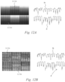
- the right-hand side of Figure 12A shows that the created dedicated descriptor Pr, such as the profile P corresponding to a projection of the values Ng of the pixels 12 of the selected patch 11 on an axis (such as a horizontal axis), may be resilient to diffusion.
- the patches 11/16 may be impacted by noise.
- the right-hand side of Figure 12B shows that the created descriptor P, such as the profile P corresponding to a projection of the values Ng of the pixels 12 of the patches 11 or 16 on an axis (such as a horizontal axis), may be resilient to noise.
- Clustering may be advantageously used with dedicated texture descriptors, such as the profiles P described above.
- Finding clusters C may aim to extract the profiles which are the most characteristics of the reference items 201 (such as cigarettes as a non-limiting example), and thus may aim to obtain patterns M for the reference items 201.
- the clustering may use K-means.
- the centre of the clusters C may then be defined as the mean of the corresponding profiles P, after a translation maximizing the correlation c.
- An idea of the patterns M extracted by clustering is illustrated by Figure 15B .
- the classifying of the patches S22 may comprise using any one of the following classifiers:
- S22 may comprise a classifier using SVM classification as for example described in the article " Support-Vector Networks” by V. Vapnick et al., Machine Learning, 1995, 20(3), p. 273-297 , and/or in the article " Learning with Kernels” by B. Scoelkopf et al., 2002, MIT Press .
- the SVM may aim to predict a class to which a texture descriptor, such as a vector, belongs to.
- the SVM may use:
- the SVM may aim to find an optimal separator SP (such as a hyperplane) between the classes 202 (such as a separation SP between the class 202 for cigarettes and the class 202 for non-cigarettes) based on the learning vectors.
- the SVM may aim to find the optimal separator SP while the distance (also called margin) between the hyperplane SP and the nearest example is kept at a maximum.
- the search for the maximum margin hyperplane SP corresponds to an optimization problem in which support vectors (i.e. in the examples of Figures 13A and 13B , the closest learning vectors to the hyperplane SP) are selected, as explained below.
- the SVM may be used, as a non-limiting example, for a binary classification such as cigarettes/non-cigarettes, as explained below.
- D Vi yi
- Vi is the descriptor (vector) of a patch 16 in the space R n of the texture features generated from S21; and yi ⁇ ⁇ 1,-1 ⁇ is the reference class 202 of Vi, i.e. (1) for cigarettes and (-1) for non-cigarettes.
- the SVM process may start by injection of Vi in a Hilbert space F, F having a high dimension, by a non-linear application ⁇ such that: ⁇ : R n ⁇ F
- the SVM may build the separator hyperplane SP defined by the equation: ⁇ ⁇ , ⁇ Vi ⁇ + b and which maximizes the error margin as illustrated by Figure 13B .
- the vectors Vi for which ⁇ i ⁇ 0 are called support-vectors.
- the data may not be linearly separable in any of the spaces of characteristics generated in S21, and in some examples a Gaussian or a polynomial kernel may be used.
- the SVM may use functions as set out in a libsvm library by C.C. Chang and C.J. Lin, available online at: http://www.csie.ntu.edu.tw/ ⁇ cjlin/libsvm/.
- the polynomial kernel function may be: ⁇ ⁇ u ′ ⁇ ⁇ + Co n
- the determination of the parameters (y,v) may be performed by cross-validation.
- the cross-validation may comprise dividing the available data into multiple subsets (e.g., 5), and evaluating the SVM on each subset using the remaining data as a learning set. The evaluation may be performed several times by varying (y,v), then keeping the best couple (y,v).
- the classifier such as the separator SP
- the learning vectors used in the search of the hyperplane SP are no longer useful, only the found support vectors are used.
- the SVM method may be thus effective in terms of complexity and processing time.
- a classifier may use a k-NN, which may aim to assign a texture of a patch 11 represented by a vector V to the most representative class 202 Vri in its immediate vicinity, as illustrated in Figure 14 .
- the k-NN method can be formally defined by: V ⁇ Vri if ⁇ j ⁇ i , Si x > Sj x where Si(x) is the number of neighbours of V belonging to the class Vri, among its k nearest neighbours.
- the k-NN method may thus select the k closest learning vectors Vri or Wri to the vector V to be classified.
- the technique of classification by k-NN may thus be a method of classification based on distances.
- the patch 11 will then be classified in the class 202 of the majority of the k-nearest neighbours.
- the choice of k may depend on the images, since a large value of k may reduce noise but may also make the decision borders less distinctive.
- k is an odd integer.
- An optimal k may be estimated by cross-validation, and k may be preferably equal to 5.
- a classifier may use a Bayesian inference.
- the correlation with each pattern M of the bench of filters is determined, and the best response Br is selected. If the selected best response Br goes over a threshold T, then it will be classified in a corresponding class 202, for example as cigarettes, i.e. class 1. If the selected best response Br does not go over the threshold T, it will be classified as non-cigarettes, i.e. class 2.
- the classifier using Bayesian inference may be based on the principle of the classifiers using margins, as illustrated in Figure 15C .
- the distance of the selected best response Br to the threshold T determines a value of confidence Vc of the classification, i.e. the further the selected best response is from the threshold T, the less the classifier is certain of its decision.
- the thresholds T may be determined by Bayesian inference for each pattern M as explained below.
- Figure 15A illustrates a patch 11 to be classified and its profile P.
- Figure 15B illustrates an example of an obtained bench of filters f, the patterns Mi as extracted by clustering, and the decision thresholds Ti.
- Figure 15C illustrates the classification of the patch 11 and the determination of the value of confidence VC.
- the classification of the patches 11 as performed in S21 and S22 is performed locally, i.e. that any selected patch 11 is classified using only its own texture descriptor.
- any selected patch 11 is classified using only its own texture descriptor.
- the classifying may thus further comprise classifying, at S23, one or more zones 13 of patches 11, each zone 13 comprising a plurality of selected patches 11 using an uniformization algorithm.
- the uniformization may take into account zones 13 of patches 11 to determine their class.
- the uniformization algorithm may be at least one of the following:
- elements which are both connected to classified patches e.g., cigarettes patches, and below a certain size may be classified in the same connected class.
- a regularization type of process may be based on the assumption that a patch 11 surrounded by patches "cigarettes" is very likely to be also a patch "cigarettes”.
- the regularization may be based on at least one of the following:
- the image 10 of Figure 16A and 16B containing the classified patches 11 may be modified into an intermediate modified image, so that the intermediate modified image may show a value of confidence (such as a distance to the nearest neighbour in the case of k-NN, or a distance to the hyperplane SP in the case of the SVM), indicating how sure the classifier is about its classification.
- the values of confidence may be probabilities that a patch 11 is, for example, cigarettes or non-cigarettes.
- Markov fields may be applied to measure a probability of an overall final result image 104, as illustrated in Figure 17A , e.g., by using a local probability of each patch 11, using only the information of each patch's neighbourhood.
- the final result image 104 may be the most probable image 104.
- the images 10 and/or 104 may be processed using Gibbs fields.
- Gibbs fields may be applied to measure a probability of an overall final result image 104, as illustrated in Figure 17A .
- Gibbs fields may have a smaller computational cost compared to Markov fields.
- a regularization type of process may minimize an Energy function.
- Maximizing the likelihood of an image may amount to minimizing the global energy U. There may be several methods to minimize the global energy.
- minimizing the global energy may be performed using an Ising model.
- ⁇ When ⁇ is positive, the most probable configurations (i.e. with the lowest energies) are those for which neighbouring patches are of the same class 202.
- the absolute value of ⁇ determines the strength of regularization of the model.
- minimizing the global energy may be performed using an Energy function.
- a simulated "annealing” may be used, for example for a Gibbs field.
- the algorithm may build a sequence of images thanks to a sampler (such as the "sampler of Metropolis") which may converge towards the distribution P TO .
- a subsequent lowering of the temperature TO in the algorithm may ensure that the last image generated by the sampler may be a global minimum of the image.
- the action may be triggered using the result image 105.
- Regularization may enable to cancel false positives and/or false negatives 18 in the final image as illustrated in Figure 18 .
- Regularization may also enable identification and/or detection of items and/or compositions, even when at least a part of the load is superimposed with a screen blocking the transmission of the inspection radiation.
- the analyser 5 may, at least partly, form a part of the inspection system 1.
- the inspection radiation source may comprise sources of other radiation, such as gamma rays or neutrons.
- the inspection radiation source may also comprise sources which are not adapted to be activated by a power supply, such as radioactive sources, such as using Co60 or Cs137.
- a computer program, computer program product, or computer readable medium comprising computer program instructions to cause a programmable computer to carry out any one or more of the methods described herein.
- at least some portions of the activities related to the analyser 5 and/or the communications networks 6 and/or 7 herein may be implemented in software. It is appreciated that software components of the present disclosure may, if desired, be implemented in ROM (read only memory) form. The software components may, generally, be implemented in hardware, if desired, using conventional techniques.
- components of the analyser 5 and/or the communications networks 6 and/or 7 may use specialized applications and hardware.
- the server 8 should not be understood as a single entity, but rather refers to a physical and/or virtual device comprising at least a processor and a memory, the memory may be comprised in one or more servers which can be located in a single location or can be remote from each other to form a distributed network (such as "server farms", e.g., using wired or wireless technology).
- server farms e.g., using wired or wireless technology
- one or more memory elements can store data used for the operations described herein. This includes the memory element being able to store software, logic, code, or processor instructions that are executed to carry out the activities described in the disclosure.
- a processor can execute any type of instructions associated with the data to achieve the operations detailed herein in the disclosure.
- the processor could transform an element or an article (e.g., data) from one state or thing to another state or thing.
- the activities outlined herein may be implemented with fixed logic or programmable logic (e.g., software/computer instructions executed by a processor) and the elements identified herein could be some type of a programmable processor, programmable digital logic (e.g., a field programmable gate array (FPGA), an erasable programmable read only memory (EPROM), an electrically erasable programmable read only memory (EEPROM)), an ASIC that includes digital logic, software, code, electronic instructions, flash memory, optical disks, CD-ROMs, DVD ROMs, magnetic or optical cards, other types of machine-readable mediums suitable for storing electronic instructions, or any suitable combination thereof.
- FPGA field programmable gate array
- EPROM erasable programmable read only memory
- EEPROM electrically eras
- the communications network 6 and the communications network 7 may form only one network.
- the data received by the analyser 5 may be typically received over a range of possible communications networks 6 and/or 7 at least such as: a satellite based communications network; a cable based communications network; a telephony based communications network; a mobile-telephony based communications network; an Internet Protocol (IP) communications network; and/or a computer based communications network.
- a satellite based communications network a cable based communications network
- a telephony based communications network a mobile-telephony based communications network
- IP Internet Protocol
- the communications networks 6 and/or 7 and/or the analyser 5 may comprise one or more networks.
- Networks may be provisioned in any form including, but not limited to, local area networks (LANs), wireless local area networks (WLANs), virtual local area networks (VLANs), metropolitan area networks (MANs), wide area networks (WANs), virtual private networks (VPNs), Intranet, Extranet, any other appropriate architecture or system, or any combination thereof that facilitates communications in a network.
- LANs local area networks
- WLANs wireless local area networks
- VLANs virtual local area networks
- MANs metropolitan area networks
- WANs wide area networks
- VPNs virtual private networks
- Intranet Extranet
- Extranet any other appropriate architecture or system, or any combination thereof that facilitates communications in a network.
Landscapes
- Engineering & Computer Science (AREA)
- Physics & Mathematics (AREA)
- General Physics & Mathematics (AREA)
- Theoretical Computer Science (AREA)
- Computer Vision & Pattern Recognition (AREA)
- Health & Medical Sciences (AREA)
- Immunology (AREA)
- Biochemistry (AREA)
- Pathology (AREA)
- General Health & Medical Sciences (AREA)
- Life Sciences & Earth Sciences (AREA)
- Chemical & Material Sciences (AREA)
- Analytical Chemistry (AREA)
- Probability & Statistics with Applications (AREA)
- Multimedia (AREA)
- Toxicology (AREA)
- Computing Systems (AREA)
- Mathematical Physics (AREA)
- Quality & Reliability (AREA)
- Analysing Materials By The Use Of Radiation (AREA)
- Image Analysis (AREA)
Description
- The present disclosure relates to methods and systems of inspection by transmission of radiation, and more particularly to inspection for identification and/or determination of a load in a container.
- The invention is defined in the appended claims.
- Known methods and systems of inspection use transmission of radiation through a container to determine the nature of its load. It is sometimes difficult to determine the nature of the load, as some different items and/or different compositions appear to be similar on inspection images generated by the known methods and systems of inspection.
- A relevant prior art is disclosed in NERCESSIAN S ET AL: "Automatic Detection of Potential Threat Objects in X-ray Luggage Scan Images", TECHNOLOGIES FOR HOMELAND SECURITY, 2008 IEEE CONFERENCE ON, IEEE, PISCATAWAY, NJ, USA, 12 May 2008 (2008-05-12), pages 504-509, XP031266648,ISBN: 978-1-4244-1977-7, which an automatic detection of potential threat objects in x-ray images of luggages, where objects in the image are being segmented and applied an edge detection process using kernels, where each 64x64 edge map is divided into 16x16 cells and the number of edge pixels in each of these cells is counted based on edge orientation to create a feature vector used for classification.
- Embodiments of the disclosure will now be described, by way of example only, with reference to the accompanying drawings, in which:
-
FIG. 1 is diagrammatic view that illustrates an example analyser in accordance with the present disclosure, configured to be connected to an inspection system in accordance with the present disclosure; -
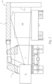
FIG. 2 is a rear view that illustrates an example of a mobile inspection system in accordance with the present disclosure, in an inspection mode; -
FIG. 3 is a rear view that illustrates an example of a static inspection system in accordance with the present disclosure, in an inspection mode; -
FIG. 4 is a flowchart that illustrates an example method in accordance with the present disclosure; -
FIG. 5 illustrates an example inspection image in accordance with the present disclosure, comprising examples of cigarettes patches; -
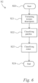
FIG. 6 is a flowchart that illustrates a detail of an example method in accordance with the present disclosure; -
FIG. 7 illustrates examples of zones of inspection images in accordance with the present disclosure, comprising examples of cigarettes patches; -
FIG. 8 illustrates examples of reference cigarettes patches in accordance with the present disclosure; -
FIG. 9 schematically illustrates an example of a texture features extractor using Quadrature Mirror Filters, QMF; -
FIG. 10A schematically illustrates an example of a decomposition of an image into three decomposition scales using a texture features extractor using Quadrature Mirror Filters, QMF; -
FIG. 10B illustrates an example of a decomposition of an image into two decomposition scales using a texture features extractor using Quadrature Mirror Filters, QMF; -
FIG. 11A schematically illustrates an example of a reference class comprising a plurality of texture descriptors Vr, referred to as "cigarettes" database orclass 1; -
FIG. 11B schematically illustrates an example of a reference class comprising a plurality of texture descriptors Wr, referred to as "non-cigarettes" database orclass 2; -
FIG. 11C schematically illustrates an example of a texture descriptor V comprising a plurality of texture features, the texture descriptor V describing a patch to be classified; -
FIG. 12A schematically illustrates examples of an impact of diffusion on a plurality of patches (left-hand side), and examples of respective dedicated texture descriptors of the plurality of patches (right-hand side); -
FIG. 12B schematically illustrates examples of an impact of noise on a plurality of patches (left-hand side), and examples of respective dedicated texture descriptor of the plurality of patches (right-hand side); -
FIG. 13A schematically illustrates an example of a classifier using a Support Vector Machine (SVM) technique; -
FIG. 13B schematically illustrates another example of a classifier using a Support Vector Machine (SVM) technique; -
FIG. 14 schematically illustrates an example of a classifier using a k nearest neighbours (k-NN) technique; -
FIG. 15A schematically illustrates an example of a patch to be classified with an example of its respective dedicated texture descriptor; -
FIG. 15B schematically illustrates an example of a bench of filters and the corresponding thresholds of decision; -
FIG. 15C schematically illustrates a response of the patch ofFigure 15A to the bench ofFigure 15B , with its corresponding value of confidence; -
FIG. 16A and 16B schematically illustrate examples of equalized images showing false positives; and -
FIG. 17A schematically illustrates an image showing a probability in each patch of the inspection image; -
FIG. 17B schematically illustrates an example generated binary image; and - FIG. 18 schematically illustrates a final image as displayed to a user.
- In the Figures like reference numerals are used to indicate like elements.
- Embodiments of the disclosure relate to a method for inspecting a load in a container by extracting one or more texture descriptors from patches of a digitized inspection image of the load, and by classifying the corresponding patches into reference classes of items using the extracted one or more texture descriptors. The classifying may involve comparing the extracted one or more texture descriptors with one or more reference texture descriptors corresponding to the reference classes. The classifying may enable e.g., detection and/or identification of the load, or may enable identification of a composition of at least a part of the load. The extraction of the texture descriptors may enable the detection and/or identification where mere analysis, without using the texture of at least a zone of interest of the image, does not allow discrimination between different items or compositions on the inspection image. The detection and/or identification may particularly be advantageous in cases where the load and/or the composition to be detected and/or identified include high value and/or contraband items and/or compositions, such as cigarettes, bank notes, drugs (such as cannabis or cocaine), medications, pills, beans (such as coffee), etc.
- Embodiments of the disclosure use texture descriptors, texture extractors and/or texture classifiers which may allow detection and/or identification of the load and/or its composition, even with a relatively small number of reference texture descriptors in the reference classes (for example a number of an order of magnitude of 1000). Alternatively or additionally, embodiments of the disclosure may enable detection and/or identification of the load and/or its composition, even with a relatively high amount of noise and/or diffusion in, and/or a relatively low resolution of, the inspection images. Alternatively or additionally, embodiments of the disclosure may enable identification and/or detection in a relative short period of time, i.e. in an order of magnitude of a second.
- Embodiments of the disclosure use classifying one or more zones of the inspection image, and thus may enable identification and/or detection, even when at least a part of the load is superimposed with a screen blocking the transmission of the inspection radiation.
- As illustrated in
Figure 7 , a texture in animage 10 is a quasi-periodic or random repetition ofbasic elements 14 having identical macroscopic visual properties. Thebasic elements 14 are called 'texels' (a short version for 'texture elements'). The texture in animage 10 of an item is one of the parameters which may be used to identify the item and/or its composition. As a non-limiting example, a texture may be identified in an image of cigarettes, since: - the cigarettes are located in packs containing a specific, regular, number of cigarettes (usually 20 cigarettes a pack),
- the packs are located in cartons containing a specific, regular, number of packs (usually 10 packs a carton),
- the cartons are located in boxes containing a specific, regular, number of cartons (for example 10 cartons a box), and
- the boxes are located in pallets containing a specific, regular, number of boxes to obtain a specific volume (for example approximately 1m3 in Europe and approximately 1.25m3 in the US).
- The texture of the
image 10 is described by at least one texture descriptor comprising texture features. As described in further detail below, the texture descriptor is extracted from values ofpixels 12 of theimage 10 and/or from spatial mutual relationships between thepixels 12 of theimage 10 corresponding to the structure of theimage 10. -
Figure 1 illustrates ananalyser 5 configured to classify one ormore patches 11 of one or moredigitized inspection images 10 of aload 101 in acontainer 100. - Each of the
images 10 is generated by aninspection system 1. - As will be apparent in more detail below, the
analyser 5 may be configured to receive the one ormore images 10 from thesystem 1, for example over a communication network 6 which may be wired and/or may be wireless. Theanalyser 5 conventionally comprises at least a processor and a memory in order to carry out an example method according to the disclosure. - As explained in further detail below in relation to
Figures 2 and3 , theinspection system 1 is configured to inspect thecontainer 100 by transmission ofinspection radiation 3 from aninspection radiation source 31 to aninspection radiation detector 32 through thecontainer 100. -
Figures 2 and3 illustrate that thecontainer 100 may be a trailer and/or a boot of a vehicle such as a truck, a van and/or a car, and/or may be a shipping container. It is appreciated that thecontainer 100 may be any type of container, and thus may be a suitcase in some examples. Theradiation source 31 is configured to cause inspection of theload 101 through the material (usually steel) of walls of thecontainer 100, e.g. for detection and/or identification of high value and/or contraband items and/or compositions, such as cigarettes, bank notes, drugs, medications, pills, beans (such as coffee beans), etc. - The
system 1 is configured to, in the inspection mode, cause inspection of thecontainer 100, in totality (i.e. thewhole container 100 is inspected) or partially (i.e. only a chosen part of the container is inspected, e.g., typically, when inspecting a vehicle, a cabin of the vehicle may not be inspected, whereas a rear part of the vehicle is inspected). - In the example illustrated by
Figure 2 , theinspection system 1 may be mobile and may be transported from a location to another location (thesystem 1 may comprise an automotive vehicle), and in the example illustrated byFigure 3 , theinspection system 1 may be static with respect to the ground and cannot be displaced. - A type of the
inspection system 1 is characterized by an energy and/or a dose of theinspection radiation 3. - In the examples illustrated by the Figures, the
inspection radiation source 31 comprises an X-ray generator. The energy of the X-rays may be comprised between 1MeV and 15MeV, and the dose may be comprised between 2mGy and 20Gy (Gray). In the example illustrated byFigure 2 , the power of theX-ray source 31 may be e.g., between 500keV and 9.0MeV, typically e.g., 2MeV, 3.5MeV, 4MeV, or 6MeV, for a steel penetration capacity e.g., between 150mm to 350mm, typically e.g., 200mm (7.9in). In the example illustrated byFigure 2 , the dose may be e.g., between 20mGy and 50mGy. In the example illustrated byFigure 3 , the power of theX-ray source 31 may be e.g., between 4MeV and 10MeV, typically e.g., 9MeV, for a steel penetration capacity e.g., between 300mm to 450mm, typically e.g., 410mm (16.1in). In the example illustrated byFigure 3 , the dose may be 17Gy. - In the examples illustrated by the Figures, the
inspection radiation detector 32 comprises, amongst other conventional electrical elements,radiation detection lines 321, such as X-ray detection lines. Theinspection radiation detector 32 may further comprise other types of detectors, such as optional gamma and/or neutrons detectors, e.g., adapted to detect the presence of radioactive gamma and/or neutrons emitting materials within thecontainer 100, e.g., simultaneously to the X-ray inspection. In the example illustrated inFigure 2 , theinspection radiation detector 32 may also comprise an electro-hydraulic boom 7 which can operate in a retracted position in a transport mode (not illustrated in the Figures) and in an inspection position (Figure 2 ). Theboom 7 may be operated by hydraulic activators (such as hydraulic cylinders). In the example illustrated inFigure 3 , theinspection radiation detector 32 may also comprise a structure and/organtry 7. The detection lines 321 may be mounted on the boom 7 (Figure 2 ) or structure and/or gantry 7 (Figure 3 ), facing thesource 31 on the other side of thecontainer 100. - In order to inspect the
container 100, in the example illustrated byFigure 2 , thesystem 1 may comprise a motion generation device so that thesystem 1 may be displaced, thecontainer 100 being static (this mode is sometimes referred to as a 'scanning' mode). Alternatively or additionally, the motion generation device may cause thecontainer 100 to be displaced, thesystem 1 being static with respect to the ground (Figure 3 ). Alternatively or additionally, in a 'pass-through' mode thesystem 1 does not comprise a motion generation device and the container moves with respect to thesystem 1, thesystem 1 being static with respect to the ground. - In some examples, the
radiation 3 may be transmitted through the container 100 (the material of thecontainer 100 being thus transparent to the radiation), while the radiation may, at least partly, be reflected by theload 101 located in the container 100 (the material and/or composition of the load located in thecontainer 100 being thus only partly transparent to theradiation 3, and partly reflective to the radiation 3 - in that case, detectors may be placed to receive the radiation reflected by the load 101). - The example method illustrated by
Figure 4 may comprise receiving, at S1, one or moredigitized images 10 from theinspection system 1. As illustrated inFigure 5 , eachdigitized image 10 comprises a plurality ofpixels 12. At least a value Ng representative of the transmission of theinspection radiation 3 through thecontainer 100 is associated with eachpixel 12. Eachpixel 12 is associated with a portion of the space and may be associated with a 102 of theload 101. - At S2, the
analyser 5 classifies one ormore patches 11 of the digitizedinspection image 10. Each of thepatches 11 is a division of theimage 10 theimage 10 being divided intosuccessive patches 11. In some examples, theanalyser 5 may divide the receivedimage 10 into thepatches 11. Alternatively or additionally, theanalyser 5 may receive theimage 10 from theinspection system 1 already divided into thepatches 11. The patches may be part of aselection 15 ofpatches 11, such as to reduce processing time by only classifying patches of interest, as explained in further detail below. - In some examples,
successive patches 11 may be overlapping each other. The overlap between twosuccessive patches 11 may take any extent, such as for example the overlap may be comprised between 10% and 90%. It is appreciated that an overlap of 10% generally reduces the number ofpatches 11 to be processed in animage 10, and thus reduces the time of processing, at a cost of a possible less accurate result, whereas an overlap of 90% generally increases the number ofpatches 11 to be processed in animage 10, and thus increases the time of processing, but gives a more accurate result. As an advantageous compromise, the overlap may be equal to 50%. - Each of the
patches 11 may be of any dimension or form. However, as will be apparent in the specification below, eachpatch 11 may form a square, with a same number of pixels on each side of thepatch 11. This may be advantageous in some examples of the disclosure, some of the algorithms requiring square patches. In an example, the number of pixels on each side of thepatch 11 may be 64, and the dimension of each patch may be then 64x64 pixels. - In some examples, the method may further comprise selecting, for further processing, only
patches 11 having a mean value Mg (Mg being the mean of the values of thepixels 12 of a patch) such that:
- T1 is a minimum threshold value for items of interest inspected by the
inspection system 1; and - T2 is a maximum threshold value for items of interest inspected by the
inspection system 1. -
Pixels 12 with values Ng above T2 usually correspond to pixels associated withbackground 160 in theimage 10, andpixels 12 with values Ng below T1 are usuallyzones 17 too dark for any detection. The selection of thepatches 11 decreases the number ofpatches 11 to process, and thus saves some processing time. For example, for values Ng encoded on 16 bits (from 0 to 65535), T1 may be for example equal to 2000 and T2 may be for example equal to 55000. - As explained in greater detail below, the method illustrated in
Figure 4 may comprise, at S3, an optional assessing of a size of apart 103 of theload 101 corresponding to a plurality of selectedpatches 11 classified in a same class, and only items withparts 103 having a size above a threshold size may be processed. This may reduce the number of false alarms. It is appreciated that the size may depend on the item. For example, it might be thatparts 103 of cigarettes below a threshold corresponding to half the size of a pallet (i.e. approximately 1/2m3 in Europe) may not be processed. The threshold size may be smaller in the case of drugs or bank notes for example. - At S4, the method comprises triggering an action based on the result of the classifying performed at S2.
- As explained in greater detail below, the action may be:
- determining a composition of the
part 103 of theload 101 corresponding to the selectedpatch 11 of theinspection image 10, - displaying the digitized inspection image with one or more determined compositions for one or
more parts 103 of theload 101, - issuing an alarm, and/or
- sending one or more selected
patches 11 to acontroller 4. - In the example illustrated by
Figure 6 , the classifying performed at S2 may comprise, for one ormore patches 11, for example in aselection 15 of one ormore patches 11 as explained in further detail below: - extracting, at S21, one or more texture descriptors V or P, for example based on the value of the
pixels 12 located in the selectedpatch 11 as explained in further detail below, and - classifying, at S22, the selected
patch 11, by comparing the one or more extracted texture descriptors of the selectedpatch 11 to one or more reference texture descriptors Vr, Wr or Pr corresponding to one ormore classes 202 ofreference items 201. - As already explained, the
reference items 201 may be, as non-limiting examples, cigarettes, bank notes, drugs (such as cannabis or cocaine), medications (such as pills or tablets), pills, beans (such as coffee beans), etc. There may thus be aclass 202 for cigarettes, aclass 202 for bank notes, aclass 202 for cannabis, etc. - As explained in greater detail below, the reference texture descriptors of each
class 202 ofreference item 201 are extracted from one ormore reference images 20 of the one ormore reference items 201, for example inspected by theinspection system 1. - In the example illustrated by
Figure 1 , the reference texture descriptors Vr, Wr or Pr, for example forming theclasses 202, are stored in areference database 200. Thedatabase 200 comprises respective reference texture descriptors Vr, Wr or Pr (and thus for example the corresponding classes 202) for each type ofinspection system 1. - In the example illustrated by
Figure 8 , the reference texture descriptors of theclass cigarettes 202 may be extracted frompatches 16 ofreference images 20 of cigarettes, as inspected by theinspection system 1. - It will be appreciated that in examples of the method in accordance with the disclosure, the
analyser 5 may be configured to retrieve the reference texture descriptors Vr, Wr or Pr from thedatabase 200 over acommunication network 7, thanks to a communication server 8 configured to provide a remote data management system. Alternatively or additionally, thedatabase 200 may be at least partially located in theanalyser 5. - In the example illustrated by
Figure 1 , the server 8 may also provide access to thedatabase 200 to a plurality of geographically distributedanalysers 5, over thenetwork 7. - As already stated, in some examples, the
database 200 may be populated fromreference items 201 inspected by theinspection system 1. - In the example illustrated by
Figure 1 , theinspection system 1 may thus sendreference images 20 to thecontroller 4 which may be further configured to extract the corresponding reference texture descriptors and thus populate thedatabase 200, for example during a phase of setting up. - In the example illustrated by
Figure 1 , one or more inspection systems 1 (of same or different types) may also sendreference images 20 ofreference items 201 to thecontroller 4 in order to further populate thedatabase 200. - Alternatively or additionally, the
analyser 5 may also send one or more selectedpatches 11 to thecontroller 4 once they have been classified in aclass 202, in order to further populate the database 200 (the one or more selectedpatches 11 may be then considered as reference patches). This allows enriching and/or updating thedatabase 200. - It will be appreciated that the disclosure may be applied to detection and/or identification of any type of item and/or composition. However, a non-limiting example for detection and/or identification of cigarettes will now be described.
- First the
reference classes 202 are built, and they may be referred to asclass 1 for "cigarettes" andclass 2 for "non-cigarettes". - In order to build the
class 1, a set ofreference images 20 containing only images of cigarettes may be divided intopatches 16 having a size of 64x64 pixels. This size of patch is advantageous, at least because a pallet of cigarettes usually occupies about 70 pixels on thedetection lines 321 of theinspection system 1. A texture descriptor (such as a vector having texture features as its dimensions, as described in more detail below) may then be extracted for eachreference cigarettes patch 16. Examples of methods of extraction of the descriptors will be described in more detail below. The set of all these texture descriptors (such as vectors) is thereference class 1. - Similarly, a set of
reference images 20 containing only images of non-cigarettes items may be divided intopatches 16 with the size 64x64 pixels. A texture descriptor may then be extracted for eachreference non-cigarettes patch 16. The set of all these descriptors is thereference class 2. - In some embodiments, the method may comprise a validation step of the reference classes and/or of the method by cross-validation. The cross-validation may comprise a step of classifying a subset of one or
more patches 16 of thereference images 20 using theother patches 16 of thereference images 20. - Then, when one wants to determine if an
inspection image 10 contains cigarettes or not, theimage 10 is divided intopatches 11 of the same size as thepatches 16 constituting the two reference classes 202 (i.e. 64x64 pixels). Eachpatch 10 is considered as being an object to be classified. - The
analyser 5 may extract the texture descriptor as for the reference descriptors. Then a classification method may be applied in order to classify thepatches 11. Examples of methods of classification will be described in more detail below. - As already stated, the method may comprise classifying one or more overlapping
successive patches 11. The overlap between two successive patches may be comprised between 10% and 90%, and may be preferably equal to 50%. - Once the
patches 11 are classified, the image may be equalized, and an action may be triggered. - The action may comprise determining a composition of the
part 103 of theload 101 corresponding to the selectedpatch 11 of theinspection image 10, such as cigarettes or drugs. The action may also be displaying the digitized inspection image with one or more determined compositions for one ormore parts 103 of theload 101, as illustrated inFigure 18 . The display may use a code of colours for the different items and/or compositions for ease of inspection by a user. An alarm (visual and/or aural) may be issue as a response to the identification and/or detection of an item and/or composition. - Each of the texture descriptor may be a generic descriptor and/or a descriptor dedicated to a
load 101 and/or areference item 201. - As explained in greater detail below, the generic descriptor may be extracted using one or more extractors among the following: a response to a bench of filters; a Haralick method implementing a matrix of co-occurrence; and/or a quadrature mirror filter, QMF.
- In some examples, the response to a bench of filters may implement, for example, Gabor filters, i.e. filters generated from a Gabor function on a plurality of scales and orientations. Gabor filters may allow extraction of textures, contours, lines and points with different orientations in
patches 11 and/or 16. - In some examples, each
patch 11 and/or 16 may be filtered by a plurality of bi-directional Gabor filters, which correspond to a convolution with a cosine kernel, weighted by a Gaussian window. The bi-directional Gabor filters may be equivalent to a local Fourier transform using a Gaussian window. The response to a bench of filters may thus enable to filter locally a bandwidth of frequencies. - For example, let
- pa represent the
patch 11 and/or 16, and - Df its frequency domain.
- Then a texture descriptor V may be calculated by convolution of pa by g, g being a Gabor filter such that:


- In some examples, two benches of filters g may be used, with the same parameters θ and λ as the parameters θ and λ set out in the article "Comparison of texture features based on Gabor filters", by Grigorescu et al., IEEE Transactions on Image Processing, 2002, vol. 11, #10, p. 1160-1167. In one of the two benches, the Gabor kernel may be symmetrical (Φ=0), and in the second of the two benches, the Gabor kernel may be anti-symmetrical (Φ=-π/2). Each bench contains 24 Gabor filters of
frequency 1/λ (with 1/λ being successively equal to 23, 31 and 47) and of orientation θ=kπ/8 (with k being successively equal to 0, 1, 2, 3, 4, 5, 6 and 7). - Therefore in some examples, as a response to each of the two benches of 24 filters as described above, a descriptor under the form of a vector V with 24 dimensions may be extracted, for each
pixel 12 in thepatch 11 and/16 of theimage - The two vectors V obtained from the symmetric and anti-symmetric benches may also be combined into a single texture descriptor which may be called "Gabor energy" Ve (the Gabor energy may be related to a modelling of human visual cortex and an ability of human neurones to perceive an orientation of contours). The Gabor energy Ve may such that:

- Matrixes of co-occurrence (short for "matrixes of co-occurrence of gray levels") may be implemented in a method of Haralick, as described in the article "Textural features for image classification", by R. M. Haralick et al., IEEE Transactions on Systems, Man and Cybernetics, November 1973, vol. SMC-3, #6, p. 610-621. The matrixes may be based on the statistical analysis of the distribution of the value Ng of the pixels 12 (linked to the intensity) in the
patch 11 and/or 16. Rather than using statistics based onindividual pixels 12, the matrixes of co-occurrence use second-order statistics obtained by considering pairs ofpixels 12. A co-occurrence matrix P(i, j / d, Θ) (which may be analogous to a bi-directional histogram) illustrates the probability (or number of occurrences) that twopixels 12, remote from each other by a distance d in a direction having an angle Θ, have intensities i and j. - The generic descriptor V obtained by a matrix of co-occurrence may comprise a plurality of texture features, such as contrast, mean and standard variation, etc. In some examples, the matrixes of co-occurrence used in a Haralick method may allow extraction of, e.g., 13 texture features for each angle Θ, such as the contrast, the mean and the standard variation already mentioned and:
- the energy f1 (or second-order angular moment):

- the entropy f2:

- the correlation f3:

- the inertia f4:

- the homogeneity f5:

- p(i, j) is an element of the matrix P,
- m is the mean of p(i,j), and
- σ is the standard deviation of p(i,j).
- Table 1 below illustrates an example of an
initial patch 11 and/or 16 withpixels 12 having values Ng e.g., comprised between 0 and 5:Table1 0 0 0 1 1 1 1 1 2 2 2 3 3 3 4 5 - Table 2 shows a matrix of co-occurrence obtained for (d,Θ)=(1,0°).
Table 2 0 1 2 3 4 5 0 2 1 0 0 0 0 1 1 3 0 0 0 0 2 0 0 2 1 0 0 3 0 0 1 1 1 0 4 0 0 0 1 0 1 5 0 0 0 0 1 0 - Table 3 shows a matrix of co-occurrence obtained for (d,Θ)=(1,90°).
Table 3 0 1 2 3 4 5 0 0 3 0 0 0 0 1 3 1 3 1 0 0 2 0 3 0 2 1 0 3 0 1 2 0 0 1 4 0 0 1 0 0 0 5 0 0 0 1 0 0 - Therefore, for six angles Θ (such as: 0°, 45°, 90°, 135°, 225°, 315°), each texture descriptor V may thus be a vector having 78 dimensions (6x13=78).
- In some examples, the descriptor may comprise a descriptor obtained by QMF. The QMF method may allow a textural analysis, both in the spatial domain and in the frequency domain. Alternatively or additionally, the QMF method may allow consistency of results between different types of
systems 1. Alternatively or additionally, the QMF method may allow better analysis for signal having discontinuities or local oddities (e.g., blurred contours). - In examples using the QMF as an extractor, each
patch patch - A wavelet transform used by the QMF decomposes a
patch patch - In the example schematically illustrated in
Figure 9 , the coefficients may be obtained by using quadrature mirror filters. A pair comprising a digital low-pass filter (H0) and a high-pass filter (H1) may be applied at each level of decomposition on an output of a previous low-pass output. In the case of apatch pixels 12 of thepatch - H0 in the two spatial directions (horizontal, i.e. lines, and vertical, i.e. columns).
- Mathematically, the wavelet transform used in the QMF may decompose a signal using a set of elementary functions generated from a single wavelet (called the 'mother wavelet') by translation and scaling, i.e. by an affine transformation of the 'mother wavelet'. Each of the wavelets has a mean which is equal to 0, and is defined on a compact interval (contrary to a Fourier transform, which uses periodic sinusoid functions defined from [-∞; +∞]).
- Let the family of wavelets ψs,u be defined by the mother wavelet ψ such that:

- s (s>0) is the parameter for the scaling; and
- u is the parameter for the translation.
- The wavelet transform transforms a function pa into coefficients cs,u such that:

- The generic descriptor may comprise thus one or more texture features. The one or more texture features may comprise the mean m and the standard deviation σ of the coefficients cs,u.
- In some examples, the wavelet transform can be implemented efficiently in a pyramid-structured wavelet transform (PSWT) or in a packet wavelet transform (PWT). In the example illustrated in
Figures 10A and 10B , at each decomposition level, thepatch - The
initial patch - In the example illustrated in
Figure 10A , theinitial patch Figure 10B illustrates an intermediate state with only two levels of decomposition of theinitial patch - In the examples illustrated by
Figures 11A and 11B , each of the texture descriptor of eachpatch Figures 11A and 11B ). - In the example illustrated by
Figure 11A , the n texture descriptors Vr1, Vr2,..., Vr16,..., Vrn correspond to respective reference texture descriptors Vri (with i=1 ...n in the example ofFigure 11A ). The reference texture descriptors Vri correspond to theclass 202 of reference forcigarettes 201. The reference texture descriptors Vri of the class ofreference cigarettes 201 may be extracted from one ormore reference images 20 ofcigarettes 201, inspected by theinspection system 1 as illustrated for example byFigure 8 . - In the example illustrated by
Figure 11B , the n texture descriptors Wr1, Wr2,..., Wr16,..., Wrn correspond to respective reference texture descriptors Wri (with i=1... n in the example ofFigure 11B ). The reference texture descriptors Wri correspond to theclass 202 of reference corresponding to anyitem 201 but cigarettes. The reference texture descriptors Wri of theclass 202 of reference for anyitem 201 but cigarettes may be extracted from one ormore reference images 20 of anyitem 201 not containing cigarettes, inspected by theinspection system 1. - The examples illustrated by
Figures 11A and 11B show that the texture descriptors Vr1, Vr2,..., Vr16, ..., Vrn and Wr1, Wr2,..., Wr16,..., Wrn may be stored in thedatabase 200. - The
reference classes 202 may contain any number n of reference descriptors Vri or Wri. It is appreciated that the more reference descriptors, the more accurate the classification. - The
classes 202 do not need to contain the same number of descriptors between them. - Each of the
patches pixels 12, such as 32x32 pixels or 128x128 pixels. It is appreciated that themore pixels 12, the more accurately the obtained descriptor, since the descriptor may comprisemore pixels 12 in each of the regions for the purpose of the calculation of the mean m and the standard deviation σ, even in the regions LH3, HH3, HL3 and LL3, at the cost of a longer processing time. In the example illustrated inFigures 10A and 10B , the initial patch has 64x64 pixels, which is a good compromise between the processing time and the number of pixels in the LH3, HH3, HL3 and LL3 regions (i.e. 8x8 pixels in the regions LH3, HH3, HL3 and LL3 ofFigure 10A ) for the calculation of mean m and the standard deviation σ in the corresponding regions. - In some embodiments, texture descriptors dedicated to a
load 101 and/or a reference item 201 (such as cigarettes, as a non-limiting example) may be created. - In some examples, the dedicated descriptor may comprise one or more descriptors such as:
- a mean grey level of the
patch 11 and/or 16, - an intensity of a vertical gradient in the patch 11 (also called 'diffusion'),
- a profile P corresponding to a projection of the values Ng of the
pixels 12 of thepatch - a clustering of a plurality of texture descriptors.
- As a non-limiting example, the above-mentioned dedicated descriptors may describe
advantageously patches - As shown in the example illustrated by
Figure 12A (on the left-hand side), on a vertical strip of thepatches Figure 3 , theradiation 3 usually passes through less material at the top of thecontainer 100, which is shown on thepatches Figure 12A shows that the created dedicated descriptor Pr, such as the profile P corresponding to a projection of the values Ng of thepixels 12 of the selectedpatch 11 on an axis (such as a horizontal axis), may be resilient to diffusion. - Furthermore, as shown in the example illustrated by
Figure 12B (on the left-hand side), thepatches 11/16 may be impacted by noise. The right-hand side ofFigure 12B shows that the created descriptor P, such as the profile P corresponding to a projection of the values Ng of thepixels 12 of thepatches - Clustering may be advantageously used with dedicated texture descriptors, such as the profiles P described above.
- Finding clusters C may aim to extract the profiles which are the most characteristics of the reference items 201 (such as cigarettes as a non-limiting example), and thus may aim to obtain patterns M for the
reference items 201. - In some examples, the clustering may use K-means. As illustrated in
Figures 12A and 12B , the profiles P are inherently periodic, and only the phase varies between them. Accordingly, a measure c of correlation of the patterns, which is invariant to translation of the patterns, may be used:

patches 16. The centre of the clusters C may then be defined as the mean of the corresponding profiles P, after a translation maximizing the correlation c. An idea of the patterns M extracted by clustering is illustrated byFigure 15B . - The advantages of clustering may include:
- noise may be decreased;
- generalization, over-learning may be avoided; and
- the obtained patterns M may serve as a bench of filters f. It is appreciated that filters dedicated to recognition of a specific shape show a better separability compared to generic filters (such as Gabor, MR8...).
- In the example illustrated by
Figure 6 , the classifying of the patches S22 may comprise using any one of the following classifiers: - a support vector machine, SVM,
- k-nearest neighbours, k-NN, and/or
- a Bayesian inference.
- In the example illustrated by
Figures 13A and 13B , S22 may comprise a classifier using SVM classification as for example described in the article "Support-Vector Networks" by V. Vapnick et al., Machine Learning, 1995, 20(3), p. 273-297, and/or in the article "Learning with Kernels" by B. Scoelkopf et al., 2002, MIT Press. The SVM may aim to predict a class to which a texture descriptor, such as a vector, belongs to. The SVM may use: - first a learning step, during which a model of
classes 202 may be determined from learning vectors (i.e. a set of example descriptors, i.e. the extracted reference descriptors Vri and/or Wri), and - second, a classification step.
- During the learning step, the SVM may aim to find an optimal separator SP (such as a hyperplane) between the classes 202 (such as a separation SP between the
class 202 for cigarettes and theclass 202 for non-cigarettes) based on the learning vectors. The SVM may aim to find the optimal separator SP while the distance (also called margin) between the hyperplane SP and the nearest example is kept at a maximum. The search for the maximum margin hyperplane SP corresponds to an optimization problem in which support vectors (i.e. in the examples ofFigures 13A and 13B , the closest learning vectors to the hyperplane SP) are selected, as explained below. - The SVM may be used, as a non-limiting example, for a binary classification such as cigarettes/non-cigarettes, as explained below.
- Let D be a training set of vectors such that:

patch 16 in the space Rn of the texture features generated from S21; and
yi ∈ {1,-1} is thereference class 202 of Vi, i.e. (1) for cigarettes and (-1) for non-cigarettes. - The SVM process may start by injection of Vi in a Hilbert space F, F having a high dimension, by a non-linear application Φ such that:

- First, let us consider that the data is linearly separable in F. Thus there exists a vector ω


- Thus, the SVM may build the separator hyperplane SP defined by the equation:

Figure 13B . - It can be shown that the vector w defining the optimal hyperplane SP is defined by:

- The vectors Vi for which αi≠0 are called support-vectors.
- The scalar product in F can be replaced by a kernel function K in Rn such that:

- In the example illustrated in
Figures 13A and 13B , the separator SP illustrated inFigure 13B is thus better than the separator SP illustrated inFigure 13A . - However, the data may not be linearly separable in any of the spaces of characteristics generated in S21, and in some examples a Gaussian or a polynomial kernel may be used.
- The SVM may use functions as set out in a libsvm library by C.C. Chang and C.J. Lin, available online at:
http://www.csie.ntu.edu.tw/~cjlin/libsvm/. - In some examples, the Gaussian kernel may be such that:

- In some other examples, the polynomial kernel function may be:

- (y,v)) are chosen parameters;
- Co is a chosen coefficient, usually 0; and
- n is the degree of the polynomial kernel function, usually 3.
- The determination of the parameters (y,v) may be performed by cross-validation. The cross-validation may comprise dividing the available data into multiple subsets (e.g., 5), and evaluating the SVM on each subset using the remaining data as a learning set. The evaluation may be performed several times by varying (y,v), then keeping the best couple (y,v).
- Once the classifier (such as the separator SP) is determined, to classify a texture descriptor (vector) of a
patch 11, the learning vectors used in the search of the hyperplane SP are no longer useful, only the found support vectors are used. The SVM method may be thus effective in terms of complexity and processing time. - In some examples, a classifier may use a k-NN, which may aim to assign a texture of a
patch 11 represented by a vector V to the mostrepresentative class 202 Vri in its immediate vicinity, as illustrated inFigure 14 . The k-NN method can be formally defined by:

- The k-NN method may thus select the k closest learning vectors Vri or Wri to the vector V to be classified. The technique of classification by k-NN may thus be a method of classification based on distances. The k-NN classifier may use any type of distance, such as the L1 distance (Manhattan),


- It is appreciated that other values of p may be used.
- The
patch 11 will then be classified in theclass 202 of the majority of the k-nearest neighbours. The choice of k may depend on the images, since a large value of k may reduce noise but may also make the decision borders less distinctive. k is an odd integer. An optimal k may be estimated by cross-validation, and k may be preferably equal to 5. - In the example illustrated by
Figures 11A, 11B and 11C , it may thus be determined whether the vector V of thepatch 11 ofFigure 11C , to be classified, has, among its 5 closest neighbours (using for example L3): - more neighbours in class 1 (cigarettes), in which case the
patch 11 is classified as cigarettes, or - more neighbours in class 2 (non-cigarettes), in which case the
patch 11 is classified as non-cigarettes. - In some examples, a classifier may use a Bayesian inference. In the example illustrated in
Figures 15A, 15B and 15C , for eachpatch 11 to be classified, the correlation with each pattern M of the bench of filters is determined, and the best response Br is selected. If the selected best response Br goes over a threshold T, then it will be classified in acorresponding class 202, for example as cigarettes, i.e.class 1. If the selected best response Br does not go over the threshold T, it will be classified as non-cigarettes, i.e.class 2. - The classifier using Bayesian inference may be based on the principle of the classifiers using margins, as illustrated in
Figure 15C . In other words, the distance of the selected best response Br to the threshold T determines a value of confidence Vc of the classification, i.e. the further the selected best response is from the threshold T, the less the classifier is certain of its decision. - In some examples, the thresholds T may be determined by Bayesian inference for each pattern M as explained below.
- Let Mi be the ith pattern, and pai k the k-th patch of all the
patches 16 of the learning set, for which Mi has obtained the best responses Bri k. - The decision threshold Ti is the one which minimizes the rate of wrong classification. or


patches 16 cigarettes and non-cigarettes, respectively. -
Figure 15A illustrates apatch 11 to be classified and its profile P. As already stated,Figure 15B illustrates an example of an obtained bench of filters f, the patterns Mi as extracted by clustering, and the decision thresholds Ti.Figure 15C illustrates the classification of thepatch 11 and the determination of the value of confidence VC. - The classification of the
patches 11 as performed in S21 and S22 is performed locally, i.e. that any selectedpatch 11 is classified using only its own texture descriptor. In other words, at the end of the classification S22, there may be isolatedpatches 11 falsely detected as cigarettes (sometimes referred to as "false positives" 18, as illustrated in the example ofFigures 16A and 16B ), but also patches "cigarettes" not recognized as such in large zones of cigarettes. - In the example illustrated in
Figure 6 , the classifying may thus further comprise classifying, at S23, one or more zones 13 ofpatches 11, each zone 13 comprising a plurality of selectedpatches 11 using an uniformization algorithm. The uniformization may take into account zones 13 ofpatches 11 to determine their class. - In some examples, the uniformization algorithm may be at least one of the following:
- a binary morphological closing,
- a segmentation, and/or
- a regularization.
- In a binary morphological closing, elements which are both connected to classified patches, e.g., cigarettes patches, and below a certain size may be classified in the same connected class.
- In a segmentation process, the image is first segmented into zones 13, and each zone 13 is classified based on a ratio ra, such that ra=(number of patches "cigarette"/number of patches "non-cigarettes") in the zone 13.
- A regularization type of process may be based on the assumption that a
patch 11 surrounded by patches "cigarettes" is very likely to be also a patch "cigarettes". - In some examples, the regularization may be based on at least one of the following:
- the Markov fields, and/or
- the Gibbs fields.
- In some examples, the
image 10 ofFigure 16A and 16B containing theclassified patches 11 may be modified into an intermediate modified image, so that the intermediate modified image may show a value of confidence (such as a distance to the nearest neighbour in the case of k-NN, or a distance to the hyperplane SP in the case of the SVM), indicating how sure the classifier is about its classification. In some examples, the values of confidence may be probabilities that apatch 11 is, for example, cigarettes or non-cigarettes. - Once the
initial image 10 has been modified in a probabilistic space in the intermediate modified image, Markov fields may be applied to measure a probability of an overallfinal result image 104, as illustrated inFigure 17A , e.g., by using a local probability of eachpatch 11, using only the information of each patch's neighbourhood. - Let
- X be a Markov field,
- I the
final result image 104 illustrated inFigure 17A , - DI the domain of I,
- pa a
patch 11 of the intermediate modified image, and - N(pa) the neighbourhood of the patch pa.
- The probability of I will thus be:

- This shows that it is unlikely that a "cigarettes" patch is in the middle of "non-cigarettes" patches and vice-versa.
- As illustrated in the example of
Figure 17A , thefinal result image 104 may be the mostprobable image 104. - Alternatively or additionally, the
images 10 and/or 104 may be processed using Gibbs fields. - Alternatively or additionally, once the
initial image 10 has been modified in a probabilistic space in the intermediate modified image, Gibbs fields may be applied to measure a probability of an overallfinal result image 104, as illustrated inFigure 17A . In some examples, Gibbs fields may have a smaller computational cost compared to Markov fields. A regularization type of process may minimize an Energy function. An Energy function U of Gibbs may be such that: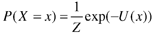

- Maximizing the likelihood of an image may amount to minimizing the global energy U. There may be several methods to minimize the global energy.
- In some examples minimizing the global energy may be performed using an Ising model.
- Let

Figure 17B , and
image 104 inFigure 17A ) of probability indicating the confidence in the classification of the patch 11 (referred to as "pa"). Considering the 4-connexity as a neighbourhood, there are only first-order potentials (i.e. thepatch 11 "pa" itself) and second-order potentials (i.e. thepatch 11 "pa" and its neighbour N(pa)). The potentials U are defined as follows:


- α is an data-attachment parameter;
- β is a coupling parameter between neighbouring patches; and
- δ is an external magnetic field.
- When β is positive, the most probable configurations (i.e. with the lowest energies) are those for which neighbouring patches are of the
same class 202. The absolute value of β determines the strength of regularization of the model. - α shows that the
result image 105 should not be fundamentally different from theimage 104 before regularization. Thus, α may be used to invert the classes of thepatches 11 only where the classifier is the least certain of its classification. - δ enables promoting, a priori, a class or another, whether it is preferable to extend the zones 13 "cigarettes" or the "non-cigarettes" zones 13.
- In some examples minimizing the global energy may be performed using an Energy function.
- In some examples, a simulated "annealing" may be used, for example for a Gibbs field.
- In some examples, a Gibbs distribution may be introduced with a temperature TO, such that:

- The algorithm may build a sequence of images thanks to a sampler (such as the "sampler of Metropolis") which may converge towards the distribution PTO. A subsequent lowering of the temperature TO in the algorithm may ensure that the last image generated by the sampler may be a global minimum of the image.
- Alternatively or additionally, other algorithms, such as iterated conditioned modes, may also be used during the regularization.
- The action may be triggered using the
result image 105. Regularization may enable to cancel false positives and/orfalse negatives 18 in the final image as illustrated inFigure 18 . - Regularization may also enable identification and/or detection of items and/or compositions, even when at least a part of the load is superimposed with a screen blocking the transmission of the inspection radiation.
- Other variations and modifications of the system or the analyser will be apparent to the skilled in the art in the context of the present disclosure, and various features described above may have advantages with or without other features described above.
- For example, the
analyser 5 may, at least partly, form a part of theinspection system 1. - It is understood that the inspection radiation source may comprise sources of other radiation, such as gamma rays or neutrons. The inspection radiation source may also comprise sources which are not adapted to be activated by a power supply, such as radioactive sources, such as using Co60 or Cs137.
- As one possibility, there is provided a computer program, computer program product, or computer readable medium, comprising computer program instructions to cause a programmable computer to carry out any one or more of the methods described herein. In example implementations, at least some portions of the activities related to the
analyser 5 and/or the communications networks 6 and/or 7 herein may be implemented in software. It is appreciated that software components of the present disclosure may, if desired, be implemented in ROM (read only memory) form. The software components may, generally, be implemented in hardware, if desired, using conventional techniques. - In some examples, components of the
analyser 5 and/or the communications networks 6 and/or 7 may use specialized applications and hardware. - As will be apparent to the skilled in the art, the server 8 should not be understood as a single entity, but rather refers to a physical and/or virtual device comprising at least a processor and a memory, the memory may be comprised in one or more servers which can be located in a single location or can be remote from each other to form a distributed network (such as "server farms", e.g., using wired or wireless technology).
- In some examples, one or more memory elements (e.g., the
database 200 and/or the memory of the processor) can store data used for the operations described herein. This includes the memory element being able to store software, logic, code, or processor instructions that are executed to carry out the activities described in the disclosure. - A processor can execute any type of instructions associated with the data to achieve the operations detailed herein in the disclosure. In one example, the processor could transform an element or an article (e.g., data) from one state or thing to another state or thing. In another example, the activities outlined herein may be implemented with fixed logic or programmable logic (e.g., software/computer instructions executed by a processor) and the elements identified herein could be some type of a programmable processor, programmable digital logic (e.g., a field programmable gate array (FPGA), an erasable programmable read only memory (EPROM), an electrically erasable programmable read only memory (EEPROM)), an ASIC that includes digital logic, software, code, electronic instructions, flash memory, optical disks, CD-ROMs, DVD ROMs, magnetic or optical cards, other types of machine-readable mediums suitable for storing electronic instructions, or any suitable combination thereof.
- The communications network 6 and the
communications network 7 may form only one network. - The data received by the
analyser 5 may be typically received over a range of possible communications networks 6 and/or 7 at least such as: a satellite based communications network; a cable based communications network; a telephony based communications network; a mobile-telephony based communications network; an Internet Protocol (IP) communications network; and/or a computer based communications network. - In some examples, the communications networks 6 and/or 7 and/or the
analyser 5 may comprise one or more networks. Networks may be provisioned in any form including, but not limited to, local area networks (LANs), wireless local area networks (WLANs), virtual local area networks (VLANs), metropolitan area networks (MANs), wide area networks (WANs), virtual private networks (VPNs), Intranet, Extranet, any other appropriate architecture or system, or any combination thereof that facilitates communications in a network.
Claims (8)
- A method for inspecting a load (101) in a container (100), comprising:
receiving (S1) a digitized image (10) from an inspection system (1) of a type of inspection system, wherein the type of inspection system (1) is characterized by an energy and a dose of the inspection radiation (3),wherein the digitized image (10) was generated by the inspection system (1) by transmission of inspection radiation (3) from an inspection radiation source (31) of the inspection system (1) to an inspection radiation detector (32) of the inspection system, through the container (100), andwherein the digitized image (10) is divided into a plurality of successive patches (11), each patch (11) of the plurality of patches (11) being a division of the image (10); and classifying (S2) one or more patches (11) of the plurality of successive patches (11), Jwherein the classifying (S2) comprises:extracting (S21) one or more texture descriptors (V, P) of a patch (11),wherein the one or more texture descriptors (V, P) are configured to describe a texture in the patch (11), the texture being a repetition of texels (14) having identical macroscopic visual properties, andwherein the texture descriptor is extracted from values of pixels (12) of the patch (11) and/or from spatial mutual relationships between the pixels (12) of the patch corresponding to the structure of the patch (11), andclassifying (S22) the patch (11), by comparing the one or more extracted texture descriptors (V, P) of the patch (11) to one or more reference texture descriptors (Vr, Wr, Pr) corresponding to one or more classes (202) of reference items (201),wherein the one or more reference texture descriptors (Vr, Wr, Pr) of each class of reference items (201) has been extracted from one or more reference images (20) of the one or more reference items (201) on a type of inspection system corresponding to the inspection system (1) generating the digitized image,wherein the one or more reference texture descriptors (Vr, Wr, Pr) corresponding to one or more classes of reference items (201) are stored in a reference database (200), andwherein the reference database (200) comprises one or more reference texture descriptors (Vr, Wr, Pr) for each type of inspection system, comprising said same type of inspection system (1) and a different type of inspection system. - The method of claim 1, further comprising triggering (S4) an action based on the classifying (S2), wherein the action is chosen from the group consisting of:determining (S41) a composition of a part (103) of the load (101) corresponding to the patch (11) of the inspection image (10),displaying (S42) the digitized inspection image (10) with one or more determined compositions for one or more parts (103) of the load (101),issuing (S43) an alarm,sending (S44) one or more classified patches (11) to a controller (4),any combination of the foregoing.
- The method of claim 1 or 2, further comprising retrieving the one or more reference texture descriptors (Vr, Wr, Pr) from the database (200) over a communication network (7), optionally wherein the database (200) is at least partially located in an analyser (5) configured to carry out a method according to any one of the preceding claims, orwherein the inspection radiation (3) comprises X-rays,optionally wherein the energy is comprised between 1MeV and 15MeV, and wherein the dose is comprised between 2mGy and 20Gy, optionally wherein for a type of inspection system (1) the energy is 9MeV and the dose is 17Gy, and wherein for another type of inspection system (1) the energy is 4MeV and the dose is 20mGy.
- An analyser (5) configured to inspect a load (101) in a container (100), configured to:receive (S1) a digitized image (10) from an inspection system (1) of a type of inspection system, wherein the type of inspection system (1) is characterized by an energy and a dose of the inspection radiation (3),wherein the digitized image (10) was generated by the inspection system (1) by transmission of inspection radiation (3) from an inspection radiation source (31) of the inspection system (1) to an inspection radiation detector (32) of the inspection system, through the container (100), andwherein the digitized image (10) is divided into a plurality of successive patches (11), each patch (11) of the plurality of patches (11) being a division of the image (10); andclassify (S2) one or more patches (11) of the plurality of successive patches (11),the analyser being configured to classify (S2) one or more patches (11) by:extracting (S21) one or more texture descriptors (V, P) of a patch (11),wherein the one or more texture descriptors (V, P) are configured to describe a texture in the patch (11), the texture being a repetition of texels (14) having identical macroscopic visual properties, andwherein the texture descriptor is extracted from values of pixels (12) of the patch (11) and/or from spatial mutual relationships between the pixels (12) of the patch corresponding to the structure of the patch (11), andclassifying (S22) the patch (11), by comparing the one or more extracted texture descriptors (V, P) of the patch (11) to one or more reference texture descriptors (Vr, Wr, Pr) corresponding to one or more classes (202) of reference items (201),wherein the one or more reference texture descriptors (Vr, Wr, Pr) of each class of reference items (201) has been extracted from one or more reference images (20) of the one or more reference items (201) on a type of inspection system corresponding to the inspection system (1) generating the digitized image,wherein the one or more reference texture descriptors (Vr, Wr, Pr) corresponding to one or more classes of reference items (201) are stored in a reference database (200), andwherein the reference database (200) comprises one or more referencetexture descriptors (Vr, Wr, Pr) for each type of inspection system, comprising said same type of inspection system (1) and a different type of inspection system.
- The analyser of claim 4, further configured to perform the method of any one of claims 2 to 3.
- Apparatus comprising:a server (8);an inspection system (1) configured to inspect a load in
a container (100) by transmission of inspection
radiation (3) from an inspection radiation source (31) to an inspection radiation detector (32) through the container (100), the inspection system (1) being of a type of inspection system, wherein the type of inspection system (1) is characterized by an energy and a dose of the inspection radiation (3),an analyser (5), connected to the server (8) and the inspection system (1) via one or more communications networks (6, 7), and configured to:receive, from the inspection system (1), a digitized inspection image (10) generated by the inspection system (1), wherein the digitized image (10) is divided into a plurality of successive patches (11), each patch (11) of the plurality of patches (11) being a division of the image (10),receive, from the server (8), one or more reference texture descriptors (Vr, Wr, Pr) corresponding to one or more classes (202) of reference items (201), the one or more reference texture descriptors (Vr, Wr, Pr) of each class of reference items (201) having been extracted from one or more reference images (20) of the one or more reference items (201) on a type of inspection system corresponding to the inspection system (1) generating the digitized image, andclassify (S2) one or more patches (11) of the plurality of successive patches (11), byextracting (S21) one or more texture descriptors (V, P) of a patch (11), wherein the one or more texture descriptors are configured to describe a texture in the patch (11), the texture being a repetition of texels (14) having identical macroscopic visual properties, and wherein the texture descriptor is extracted from values of pixels (12) of the patch (11) and/or from spatial mutual relationships between the pixels (12) of the patch corresponding to the structure of the patch (11),and classifying (S22)the patch (11), by comparing the one or more extracted texture descriptors (V, P) of the patch (11) to the one or more reference texture descriptors (Vr, Wr, Pr),wherein the one or more reference texture descriptors (Vr, Wr, Pr) corresponding to one or more classes of reference items (201) are stored in a reference database (200), andwherein the reference database (200) comprises one or more reference texturedescriptors (Vr, Wr, Pr) for each type of inspection system, comprising said same type of inspection system (1) and a different type of inspection system. - The apparatus of claim 6, comprising the analyser of claim 5.
- A computer program product comprising program instructions which, when the program is executed by a processor, cause the processor to carry out the method according to any one of claims 1 to 3.
Applications Claiming Priority (2)
| Application Number | Priority Date | Filing Date | Title |
|---|---|---|---|
| GB1406887.8A GB2525228B (en) | 2014-04-16 | 2014-04-16 | Identification or determination of a load based on texture |
| PCT/GB2015/050934 WO2015159045A1 (en) | 2014-04-16 | 2015-03-27 | Identification or determination of a load based on texture |
Publications (3)
| Publication Number | Publication Date |
|---|---|
| EP3132378A1 EP3132378A1 (en) | 2017-02-22 |
| EP3132378B1 true EP3132378B1 (en) | 2024-10-23 |
| EP3132378B8 EP3132378B8 (en) | 2024-11-27 |
Family
ID=50845127
Family Applications (1)
| Application Number | Title | Priority Date | Filing Date |
|---|---|---|---|
| EP15722738.0A Active EP3132378B8 (en) | 2014-04-16 | 2015-03-27 | Identification or determination of a load based on texture |
Country Status (8)
| Country | Link |
|---|---|
| US (1) | US10134147B2 (en) |
| EP (1) | EP3132378B8 (en) |
| CN (1) | CN106663190B (en) |
| BR (1) | BR112016024190B1 (en) |
| GB (1) | GB2525228B (en) |
| PL (1) | PL3132378T3 (en) |
| RU (1) | RU2717913C2 (en) |
| WO (1) | WO2015159045A1 (en) |
Families Citing this family (13)
| Publication number | Priority date | Publication date | Assignee | Title |
|---|---|---|---|---|
| WO2016014041A1 (en) * | 2014-07-22 | 2016-01-28 | Hewlett-Packard Development Company, L.P. | Rapid image registration |
| EP3772702A3 (en) | 2016-02-22 | 2021-05-19 | Rapiscan Systems, Inc. | Methods for processing radiographic images |
| GB2556941B (en) * | 2016-11-28 | 2021-10-20 | Smiths Heimann Sas | Detection of irregularities using registration |
| US10268924B2 (en) * | 2016-12-05 | 2019-04-23 | Sap Se | Systems and methods for integrated cargo inspection |
| CN108572183B (en) * | 2017-03-08 | 2021-11-30 | 清华大学 | Inspection apparatus and method of segmenting vehicle image |
| EP3682372A4 (en) * | 2017-09-14 | 2021-07-21 | Chevron U.S.A. Inc. | CLASSIFICATION OF STRINGS USING MACHINE LEARNING |
| US11058143B2 (en) | 2017-10-19 | 2021-07-13 | R.J. Reynolds Tobacco Company | Smoking-related article inspection systems and associated methods |
| EP3746963A4 (en) * | 2018-02-02 | 2021-11-03 | Digital Logistics As | LOAD DETECTION AND TRACKING |
| CN109859125B (en) * | 2019-01-14 | 2022-10-21 | 广东工业大学 | Image Highlight Restoration Method Based on Morphological Detection and Wavelet Transform |
| CN111476938B (en) * | 2019-01-24 | 2023-04-28 | 中科晶源微电子技术(北京)有限公司 | Anomaly detection for periodic patterns |
| CN111784675A (en) * | 2020-07-01 | 2020-10-16 | 云南易见纹语科技有限公司 | Method and device for processing article texture information, storage medium and electronic equipment |
| CN113298138B (en) * | 2021-05-21 | 2024-04-23 | 西安建筑科技大学 | Individual identification method and system for radar radiation source |
| CN118154979B (en) * | 2024-04-02 | 2024-11-29 | 宁波大学 | SMRI image classification method based on feature separation |
Family Cites Families (7)
| Publication number | Priority date | Publication date | Assignee | Title |
|---|---|---|---|---|
| EP0412189B1 (en) * | 1989-08-09 | 1992-10-28 | Heimann Systems GmbH & Co. KG | Device for transmitting fan-shaped radiation through objects |
| US5319547A (en) * | 1990-08-10 | 1994-06-07 | Vivid Technologies, Inc. | Device and method for inspection of baggage and other objects |
| US5600303A (en) * | 1993-01-15 | 1997-02-04 | Technology International Incorporated | Detection of concealed explosives and contraband |
| US5838759A (en) * | 1996-07-03 | 1998-11-17 | Advanced Research And Applications Corporation | Single beam photoneutron probe and X-ray imaging system for contraband detection and identification |
| RU2204122C2 (en) * | 2001-06-25 | 2003-05-10 | Федеральное государственное унитарное предприятие "Московский радиотехнический институт РАН" | X-ray/tv facility |
| US20090174554A1 (en) * | 2005-05-11 | 2009-07-09 | Eric Bergeron | Method and system for screening luggage items, cargo containers or persons |
| CN101071109B (en) * | 2006-05-08 | 2010-05-12 | 清华大学 | A Cargo Security Inspection System Based on Multi-segment Linear Trajectory Imaging |
-
2014
- 2014-04-16 GB GB1406887.8A patent/GB2525228B/en active Active
-
2015
- 2015-03-27 PL PL15722738.0T patent/PL3132378T3/en unknown
- 2015-03-27 WO PCT/GB2015/050934 patent/WO2015159045A1/en not_active Ceased
- 2015-03-27 US US15/304,377 patent/US10134147B2/en active Active
- 2015-03-27 CN CN201580032216.9A patent/CN106663190B/en active Active
- 2015-03-27 EP EP15722738.0A patent/EP3132378B8/en active Active
- 2015-03-27 BR BR112016024190-8A patent/BR112016024190B1/en active IP Right Grant
- 2015-03-27 RU RU2016143754A patent/RU2717913C2/en active
Also Published As
| Publication number | Publication date |
|---|---|
| US20170046852A1 (en) | 2017-02-16 |
| RU2016143754A (en) | 2018-05-16 |
| EP3132378A1 (en) | 2017-02-22 |
| RU2016143754A3 (en) | 2018-11-12 |
| RU2717913C2 (en) | 2020-03-26 |
| US10134147B2 (en) | 2018-11-20 |
| BR112016024190A2 (en) | 2017-10-10 |
| EP3132378B8 (en) | 2024-11-27 |
| BR112016024190B1 (en) | 2022-11-01 |
| CN106663190B (en) | 2020-06-19 |
| CN106663190A (en) | 2017-05-10 |
| GB201406887D0 (en) | 2014-05-28 |
| WO2015159045A1 (en) | 2015-10-22 |
| GB2525228B (en) | 2020-05-06 |
| GB2525228A (en) | 2015-10-21 |
| PL3132378T3 (en) | 2025-03-31 |
Similar Documents
| Publication | Publication Date | Title |
|---|---|---|
| US10134147B2 (en) | Identification or determination of a load based on texture | |
| Griffin et al. | “unexpected item in the bagging area”: Anomaly detection in x-ray security images | |
| Salehi et al. | Improving the accuracy of urban land cover classification using Radarsat-2 PolSAR data | |
| Petrich et al. | Machine learning for defect detection for PBFAM using high resolution layerwise imaging coupled with post-build CT scans | |
| EP3545493B1 (en) | Detection of irregularities using registration | |
| US10529079B2 (en) | Target detection, tracking, and classification in compressive measurement domain | |
| US20110026804A1 (en) | Detection of Textural Defects Using a One Class Support Vector Machine | |
| Nercessian et al. | Automatic detection of potential threat objects in X-ray luggage scan images | |
| EP3869400A1 (en) | Object identification system and computer-implemented method | |
| Farooq et al. | A generic passive image forgery detection scheme using local binary pattern with rich models | |
| Imani et al. | GLCM, Gabor, and morphology profiles fusion for hyperspectral image classification | |
| Kiaee et al. | Using GLCM features in Haar wavelet transformed space for moving object classification | |
| Zhang et al. | Change detection for the urban area based on multiple sensor information fusion | |
| Hou et al. | FMRSS Net: Fast Matrix Representation‐Based Spectral‐Spatial Feature Learning Convolutional Neural Network for Hyperspectral Image Classification | |
| Lukin et al. | Classification of pre-filtered multichannel remote sensing images | |
| Ma et al. | Hyper-Laplacian regularized low-rank tensor decomposition for hyperspectral anomaly detection | |
| Jablonski | Reconstruction error and principal component based anomaly detection in hyperspectral imagery | |
| CN119762457B (en) | ISAL image quality evaluation method based on Bior and RDSIFT algorithms | |
| Shibi et al. | Performance Analysis of Hyperspectral Supervised Target Detection Algorithms | |
| Sun et al. | Accumulating pyramid spatial-spectral collaborative coding divergence for hyperspectral anomaly detection | |
| Osaku et al. | On the influence of markovian models for contextual-based optimum-path forest classification | |
| Meng et al. | CFAR and KPCA for SAR image target detection | |
| Brisebarre et al. | Hyperspectral change detection by direction pursuit | |
| Willis | Comparison of anomaly detection methods for hyperspectral imagery | |
| Vijayalakshm et al. | Analysis of SAR images with various change detection techniques |
Legal Events
| Date | Code | Title | Description |
|---|---|---|---|
| STAA | Information on the status of an ep patent application or granted ep patent |
Free format text: STATUS: THE INTERNATIONAL PUBLICATION HAS BEEN MADE |
|
| PUAI | Public reference made under article 153(3) epc to a published international application that has entered the european phase |
Free format text: ORIGINAL CODE: 0009012 |
|
| STAA | Information on the status of an ep patent application or granted ep patent |
Free format text: STATUS: REQUEST FOR EXAMINATION WAS MADE |
|
| 17P | Request for examination filed |
Effective date: 20161115 |
|
| AK | Designated contracting states |
Kind code of ref document: A1 Designated state(s): AL AT BE BG CH CY CZ DE DK EE ES FI FR GB GR HR HU IE IS IT LI LT LU LV MC MK MT NL NO PL PT RO RS SE SI SK SM TR |
|
| AX | Request for extension of the european patent |
Extension state: BA ME |
|
| DAV | Request for validation of the european patent (deleted) | ||
| DAX | Request for extension of the european patent (deleted) | ||
| STAA | Information on the status of an ep patent application or granted ep patent |
Free format text: STATUS: EXAMINATION IS IN PROGRESS |
|
| 17Q | First examination report despatched |
Effective date: 20220421 |
|
| REG | Reference to a national code |
Ref country code: DE Free format text: PREVIOUS MAIN CLASS: G06K0009000000 Ipc: G01N0023040000 Ref country code: DE Ref legal event code: R079 Ref document number: 602015090198 Country of ref document: DE Free format text: PREVIOUS MAIN CLASS: G06K0009000000 Ipc: G01N0023040000 |
|
| GRAP | Despatch of communication of intention to grant a patent |
Free format text: ORIGINAL CODE: EPIDOSNIGR1 |
|
| STAA | Information on the status of an ep patent application or granted ep patent |
Free format text: STATUS: GRANT OF PATENT IS INTENDED |
|
| RIC1 | Information provided on ipc code assigned before grant |
Ipc: G06V 10/54 20220101ALI20240424BHEP Ipc: G06F 18/00 20230101ALI20240424BHEP Ipc: G01N 23/04 20060101AFI20240424BHEP |
|
| INTG | Intention to grant announced |
Effective date: 20240515 |
|
| GRAS | Grant fee paid |
Free format text: ORIGINAL CODE: EPIDOSNIGR3 |
|
| GRAA | (expected) grant |
Free format text: ORIGINAL CODE: 0009210 |
|
| STAA | Information on the status of an ep patent application or granted ep patent |
Free format text: STATUS: THE PATENT HAS BEEN GRANTED |
|
| RAP3 | Party data changed (applicant data changed or rights of an application transferred) |
Owner name: SMITHS DETECTION FRANCE S.A.S. |
|
| RIN1 | Information on inventor provided before grant (corrected) |
Inventor name: GADI, NAJIB |
|
| AK | Designated contracting states |
Kind code of ref document: B1 Designated state(s): AL AT BE BG CH CY CZ DE DK EE ES FI FR GB GR HR HU IE IS IT LI LT LU LV MC MK MT NL NO PL PT RO RS SE SI SK SM TR |
|
| REG | Reference to a national code |
Ref country code: GB Ref legal event code: FG4D |
|
| REG | Reference to a national code |
Ref country code: CH Ref legal event code: PK Free format text: BERICHTIGUNG B8 Ref country code: CH Ref legal event code: EP |
|
| RBV | Designated contracting states (corrected) |
Designated state(s): AL AT BE BG CH CY CZ DE DK EE ES FI FR GR HR HU IE IS IT LI LT LU LV MC MK MT NL NO PL PT RO RS SE SI SK SM TR |
|
| REG | Reference to a national code |
Ref country code: DE Ref legal event code: R096 Ref document number: 602015090198 Country of ref document: DE |
|
| REG | Reference to a national code |
Ref country code: IE Ref legal event code: FG4D |
|
| REG | Reference to a national code |
Ref country code: NL Ref legal event code: FP |
|
| P01 | Opt-out of the competence of the unified patent court (upc) registered |
Free format text: CASE NUMBER: APP_2022/2025 Effective date: 20250113 |
|
| REG | Reference to a national code |
Ref country code: LT Ref legal event code: MG9D |
|
| REG | Reference to a national code |
Ref country code: AT Ref legal event code: MK05 Ref document number: 1735221 Country of ref document: AT Kind code of ref document: T Effective date: 20241023 |
|
| PG25 | Lapsed in a contracting state [announced via postgrant information from national office to epo] |
Ref country code: HR Free format text: LAPSE BECAUSE OF FAILURE TO SUBMIT A TRANSLATION OF THE DESCRIPTION OR TO PAY THE FEE WITHIN THE PRESCRIBED TIME-LIMIT Effective date: 20241023 Ref country code: IS Free format text: LAPSE BECAUSE OF FAILURE TO SUBMIT A TRANSLATION OF THE DESCRIPTION OR TO PAY THE FEE WITHIN THE PRESCRIBED TIME-LIMIT Effective date: 20250223 Ref country code: PT Free format text: LAPSE BECAUSE OF FAILURE TO SUBMIT A TRANSLATION OF THE DESCRIPTION OR TO PAY THE FEE WITHIN THE PRESCRIBED TIME-LIMIT Effective date: 20250224 |
|
| PG25 | Lapsed in a contracting state [announced via postgrant information from national office to epo] |
Ref country code: FI Free format text: LAPSE BECAUSE OF FAILURE TO SUBMIT A TRANSLATION OF THE DESCRIPTION OR TO PAY THE FEE WITHIN THE PRESCRIBED TIME-LIMIT Effective date: 20241023 |
|
| PG25 | Lapsed in a contracting state [announced via postgrant information from national office to epo] |
Ref country code: BG Free format text: LAPSE BECAUSE OF FAILURE TO SUBMIT A TRANSLATION OF THE DESCRIPTION OR TO PAY THE FEE WITHIN THE PRESCRIBED TIME-LIMIT Effective date: 20241023 |
|
| PG25 | Lapsed in a contracting state [announced via postgrant information from national office to epo] |
Ref country code: ES Free format text: LAPSE BECAUSE OF FAILURE TO SUBMIT A TRANSLATION OF THE DESCRIPTION OR TO PAY THE FEE WITHIN THE PRESCRIBED TIME-LIMIT Effective date: 20241023 |
|
| PG25 | Lapsed in a contracting state [announced via postgrant information from national office to epo] |
Ref country code: NO Free format text: LAPSE BECAUSE OF FAILURE TO SUBMIT A TRANSLATION OF THE DESCRIPTION OR TO PAY THE FEE WITHIN THE PRESCRIBED TIME-LIMIT Effective date: 20250123 |
|
| PG25 | Lapsed in a contracting state [announced via postgrant information from national office to epo] |
Ref country code: LV Free format text: LAPSE BECAUSE OF FAILURE TO SUBMIT A TRANSLATION OF THE DESCRIPTION OR TO PAY THE FEE WITHIN THE PRESCRIBED TIME-LIMIT Effective date: 20241023 Ref country code: AT Free format text: LAPSE BECAUSE OF FAILURE TO SUBMIT A TRANSLATION OF THE DESCRIPTION OR TO PAY THE FEE WITHIN THE PRESCRIBED TIME-LIMIT Effective date: 20241023 Ref country code: GR Free format text: LAPSE BECAUSE OF FAILURE TO SUBMIT A TRANSLATION OF THE DESCRIPTION OR TO PAY THE FEE WITHIN THE PRESCRIBED TIME-LIMIT Effective date: 20250124 |
|
| PG25 | Lapsed in a contracting state [announced via postgrant information from national office to epo] |
Ref country code: RS Free format text: LAPSE BECAUSE OF FAILURE TO SUBMIT A TRANSLATION OF THE DESCRIPTION OR TO PAY THE FEE WITHIN THE PRESCRIBED TIME-LIMIT Effective date: 20250123 |
|
| PG25 | Lapsed in a contracting state [announced via postgrant information from national office to epo] |
Ref country code: SM Free format text: LAPSE BECAUSE OF FAILURE TO SUBMIT A TRANSLATION OF THE DESCRIPTION OR TO PAY THE FEE WITHIN THE PRESCRIBED TIME-LIMIT Effective date: 20241023 |
|
| PG25 | Lapsed in a contracting state [announced via postgrant information from national office to epo] |
Ref country code: DK Free format text: LAPSE BECAUSE OF FAILURE TO SUBMIT A TRANSLATION OF THE DESCRIPTION OR TO PAY THE FEE WITHIN THE PRESCRIBED TIME-LIMIT Effective date: 20241023 |
|
| PG25 | Lapsed in a contracting state [announced via postgrant information from national office to epo] |
Ref country code: RO Free format text: LAPSE BECAUSE OF FAILURE TO SUBMIT A TRANSLATION OF THE DESCRIPTION OR TO PAY THE FEE WITHIN THE PRESCRIBED TIME-LIMIT Effective date: 20241023 |
|
| REG | Reference to a national code |
Ref country code: DE Ref legal event code: R097 Ref document number: 602015090198 Country of ref document: DE |
|
| PG25 | Lapsed in a contracting state [announced via postgrant information from national office to epo] |
Ref country code: SK Free format text: LAPSE BECAUSE OF FAILURE TO SUBMIT A TRANSLATION OF THE DESCRIPTION OR TO PAY THE FEE WITHIN THE PRESCRIBED TIME-LIMIT Effective date: 20241023 |
|
| PG25 | Lapsed in a contracting state [announced via postgrant information from national office to epo] |
Ref country code: CZ Free format text: LAPSE BECAUSE OF FAILURE TO SUBMIT A TRANSLATION OF THE DESCRIPTION OR TO PAY THE FEE WITHIN THE PRESCRIBED TIME-LIMIT Effective date: 20241023 |
|
| PLBE | No opposition filed within time limit |
Free format text: ORIGINAL CODE: 0009261 |
|
| STAA | Information on the status of an ep patent application or granted ep patent |
Free format text: STATUS: NO OPPOSITION FILED WITHIN TIME LIMIT |
|
| PG25 | Lapsed in a contracting state [announced via postgrant information from national office to epo] |
Ref country code: SE Free format text: LAPSE BECAUSE OF FAILURE TO SUBMIT A TRANSLATION OF THE DESCRIPTION OR TO PAY THE FEE WITHIN THE PRESCRIBED TIME-LIMIT Effective date: 20241023 |
|
| 26N | No opposition filed |
Effective date: 20250724 |
|
| PG25 | Lapsed in a contracting state [announced via postgrant information from national office to epo] |
Ref country code: MC Free format text: LAPSE BECAUSE OF FAILURE TO SUBMIT A TRANSLATION OF THE DESCRIPTION OR TO PAY THE FEE WITHIN THE PRESCRIBED TIME-LIMIT Effective date: 20241023 |
|
| REG | Reference to a national code |
Ref country code: CH Ref legal event code: H13 Free format text: ST27 STATUS EVENT CODE: U-0-0-H10-H13 (AS PROVIDED BY THE NATIONAL OFFICE) Effective date: 20251023 |
|
| PG25 | Lapsed in a contracting state [announced via postgrant information from national office to epo] |
Ref country code: LU Free format text: LAPSE BECAUSE OF NON-PAYMENT OF DUE FEES Effective date: 20250327 |
|
| REG | Reference to a national code |
Ref country code: BE Ref legal event code: MM Effective date: 20250331 |
|
| PGFP | Annual fee paid to national office [announced via postgrant information from national office to epo] |
Ref country code: FR Payment date: 20251231 Year of fee payment: 12 |
|
| PG25 | Lapsed in a contracting state [announced via postgrant information from national office to epo] |
Ref country code: BE Free format text: LAPSE BECAUSE OF NON-PAYMENT OF DUE FEES Effective date: 20250331 |
|
| PG25 | Lapsed in a contracting state [announced via postgrant information from national office to epo] |
Ref country code: CH Free format text: LAPSE BECAUSE OF NON-PAYMENT OF DUE FEES Effective date: 20250331 |
|
| PG25 | Lapsed in a contracting state [announced via postgrant information from national office to epo] |
Ref country code: IE Free format text: LAPSE BECAUSE OF NON-PAYMENT OF DUE FEES Effective date: 20250327 |
|
| PGFP | Annual fee paid to national office [announced via postgrant information from national office to epo] |
Ref country code: NL Payment date: 20260106 Year of fee payment: 12 |
|
| PGFP | Annual fee paid to national office [announced via postgrant information from national office to epo] |
Ref country code: DE Payment date: 20260102 Year of fee payment: 12 |
|
| PGFP | Annual fee paid to national office [announced via postgrant information from national office to epo] |
Ref country code: IT Payment date: 20260220 Year of fee payment: 12 |
|
| PGFP | Annual fee paid to national office [announced via postgrant information from national office to epo] |
Ref country code: PL Payment date: 20260112 Year of fee payment: 12 |