EP3131149A1 - Flat-type secondary battery - Google Patents
Flat-type secondary battery Download PDFInfo
- Publication number
- EP3131149A1 EP3131149A1 EP15776372.3A EP15776372A EP3131149A1 EP 3131149 A1 EP3131149 A1 EP 3131149A1 EP 15776372 A EP15776372 A EP 15776372A EP 3131149 A1 EP3131149 A1 EP 3131149A1
- Authority
- EP
- European Patent Office
- Prior art keywords
- secondary battery
- length
- power generation
- sealing
- electrodes
- Prior art date
- Legal status (The legal status is an assumption and is not a legal conclusion. Google has not performed a legal analysis and makes no representation as to the accuracy of the status listed.)
- Granted
Links
Images








Classifications
-
- H—ELECTRICITY
- H01—ELECTRIC ELEMENTS
- H01M—PROCESSES OR MEANS, e.g. BATTERIES, FOR THE DIRECT CONVERSION OF CHEMICAL ENERGY INTO ELECTRICAL ENERGY
- H01M10/00—Secondary cells; Manufacture thereof
- H01M10/05—Accumulators with non-aqueous electrolyte
- H01M10/058—Construction or manufacture
- H01M10/0585—Construction or manufacture of accumulators having only flat construction elements, i.e. flat positive electrodes, flat negative electrodes and flat separators
-
- H—ELECTRICITY
- H01—ELECTRIC ELEMENTS
- H01M—PROCESSES OR MEANS, e.g. BATTERIES, FOR THE DIRECT CONVERSION OF CHEMICAL ENERGY INTO ELECTRICAL ENERGY
- H01M10/00—Secondary cells; Manufacture thereof
- H01M10/04—Construction or manufacture in general
- H01M10/0413—Large-sized flat cells or batteries for motive or stationary systems with plate-like electrodes
-
- H—ELECTRICITY
- H01—ELECTRIC ELEMENTS
- H01M—PROCESSES OR MEANS, e.g. BATTERIES, FOR THE DIRECT CONVERSION OF CHEMICAL ENERGY INTO ELECTRICAL ENERGY
- H01M10/00—Secondary cells; Manufacture thereof
- H01M10/04—Construction or manufacture in general
- H01M10/0436—Small-sized flat cells or batteries for portable equipment
-
- H—ELECTRICITY
- H01—ELECTRIC ELEMENTS
- H01M—PROCESSES OR MEANS, e.g. BATTERIES, FOR THE DIRECT CONVERSION OF CHEMICAL ENERGY INTO ELECTRICAL ENERGY
- H01M10/00—Secondary cells; Manufacture thereof
- H01M10/05—Accumulators with non-aqueous electrolyte
- H01M10/052—Li-accumulators
- H01M10/0525—Rocking-chair batteries, i.e. batteries with lithium insertion or intercalation in both electrodes; Lithium-ion batteries
-
- H—ELECTRICITY
- H01—ELECTRIC ELEMENTS
- H01M—PROCESSES OR MEANS, e.g. BATTERIES, FOR THE DIRECT CONVERSION OF CHEMICAL ENERGY INTO ELECTRICAL ENERGY
- H01M10/00—Secondary cells; Manufacture thereof
- H01M10/05—Accumulators with non-aqueous electrolyte
- H01M10/056—Accumulators with non-aqueous electrolyte characterised by the materials used as electrolytes, e.g. mixed inorganic/organic electrolytes
- H01M10/0564—Accumulators with non-aqueous electrolyte characterised by the materials used as electrolytes, e.g. mixed inorganic/organic electrolytes the electrolyte being constituted of organic materials only
- H01M10/0566—Liquid materials
- H01M10/0569—Liquid materials characterised by the solvents
-
- H—ELECTRICITY
- H01—ELECTRIC ELEMENTS
- H01M—PROCESSES OR MEANS, e.g. BATTERIES, FOR THE DIRECT CONVERSION OF CHEMICAL ENERGY INTO ELECTRICAL ENERGY
- H01M4/00—Electrodes
- H01M4/02—Electrodes composed of, or comprising, active material
- H01M4/36—Selection of substances as active materials, active masses, active liquids
- H01M4/48—Selection of substances as active materials, active masses, active liquids of inorganic oxides or hydroxides
- H01M4/50—Selection of substances as active materials, active masses, active liquids of inorganic oxides or hydroxides of manganese
- H01M4/505—Selection of substances as active materials, active masses, active liquids of inorganic oxides or hydroxides of manganese of mixed oxides or hydroxides containing manganese for inserting or intercalating light metals, e.g. LiMn2O4 or LiMn2OxFy
-
- H—ELECTRICITY
- H01—ELECTRIC ELEMENTS
- H01M—PROCESSES OR MEANS, e.g. BATTERIES, FOR THE DIRECT CONVERSION OF CHEMICAL ENERGY INTO ELECTRICAL ENERGY
- H01M4/00—Electrodes
- H01M4/02—Electrodes composed of, or comprising, active material
- H01M4/36—Selection of substances as active materials, active masses, active liquids
- H01M4/48—Selection of substances as active materials, active masses, active liquids of inorganic oxides or hydroxides
- H01M4/52—Selection of substances as active materials, active masses, active liquids of inorganic oxides or hydroxides of nickel, cobalt or iron
- H01M4/525—Selection of substances as active materials, active masses, active liquids of inorganic oxides or hydroxides of nickel, cobalt or iron of mixed oxides or hydroxides containing iron, cobalt or nickel for inserting or intercalating light metals, e.g. LiNiO2, LiCoO2 or LiCoOxFy
-
- H—ELECTRICITY
- H01—ELECTRIC ELEMENTS
- H01M—PROCESSES OR MEANS, e.g. BATTERIES, FOR THE DIRECT CONVERSION OF CHEMICAL ENERGY INTO ELECTRICAL ENERGY
- H01M4/00—Electrodes
- H01M4/02—Electrodes composed of, or comprising, active material
- H01M4/36—Selection of substances as active materials, active masses, active liquids
- H01M4/58—Selection of substances as active materials, active masses, active liquids of inorganic compounds other than oxides or hydroxides, e.g. sulfides, selenides, tellurides, halogenides or LiCoFy; of polyanionic structures, e.g. phosphates, silicates or borates
- H01M4/583—Carbonaceous material, e.g. graphite-intercalation compounds or CFx
- H01M4/587—Carbonaceous material, e.g. graphite-intercalation compounds or CFx for inserting or intercalating light metals
-
- H—ELECTRICITY
- H01—ELECTRIC ELEMENTS
- H01M—PROCESSES OR MEANS, e.g. BATTERIES, FOR THE DIRECT CONVERSION OF CHEMICAL ENERGY INTO ELECTRICAL ENERGY
- H01M4/00—Electrodes
- H01M4/02—Electrodes composed of, or comprising, active material
- H01M4/62—Selection of inactive substances as ingredients for active masses, e.g. binders, fillers
- H01M4/621—Binders
- H01M4/622—Binders being polymers
- H01M4/623—Binders being polymers fluorinated polymers
-
- H—ELECTRICITY
- H01—ELECTRIC ELEMENTS
- H01M—PROCESSES OR MEANS, e.g. BATTERIES, FOR THE DIRECT CONVERSION OF CHEMICAL ENERGY INTO ELECTRICAL ENERGY
- H01M50/00—Constructional details or processes of manufacture of the non-active parts of electrochemical cells other than fuel cells, e.g. hybrid cells
- H01M50/10—Primary casings; Jackets or wrappings
- H01M50/102—Primary casings; Jackets or wrappings characterised by their shape or physical structure
- H01M50/103—Primary casings; Jackets or wrappings characterised by their shape or physical structure prismatic or rectangular
-
- H—ELECTRICITY
- H01—ELECTRIC ELEMENTS
- H01M—PROCESSES OR MEANS, e.g. BATTERIES, FOR THE DIRECT CONVERSION OF CHEMICAL ENERGY INTO ELECTRICAL ENERGY
- H01M50/00—Constructional details or processes of manufacture of the non-active parts of electrochemical cells other than fuel cells, e.g. hybrid cells
- H01M50/10—Primary casings; Jackets or wrappings
- H01M50/102—Primary casings; Jackets or wrappings characterised by their shape or physical structure
- H01M50/105—Pouches or flexible bags
-
- H—ELECTRICITY
- H01—ELECTRIC ELEMENTS
- H01M—PROCESSES OR MEANS, e.g. BATTERIES, FOR THE DIRECT CONVERSION OF CHEMICAL ENERGY INTO ELECTRICAL ENERGY
- H01M50/00—Constructional details or processes of manufacture of the non-active parts of electrochemical cells other than fuel cells, e.g. hybrid cells
- H01M50/10—Primary casings; Jackets or wrappings
- H01M50/183—Sealing members
- H01M50/186—Sealing members characterised by the disposition of the sealing members
-
- H—ELECTRICITY
- H01—ELECTRIC ELEMENTS
- H01M—PROCESSES OR MEANS, e.g. BATTERIES, FOR THE DIRECT CONVERSION OF CHEMICAL ENERGY INTO ELECTRICAL ENERGY
- H01M2300/00—Electrolytes
- H01M2300/0017—Non-aqueous electrolytes
- H01M2300/0025—Organic electrolyte
- H01M2300/0028—Organic electrolyte characterised by the solvent
- H01M2300/0037—Mixture of solvents
- H01M2300/004—Three solvents
-
- Y—GENERAL TAGGING OF NEW TECHNOLOGICAL DEVELOPMENTS; GENERAL TAGGING OF CROSS-SECTIONAL TECHNOLOGIES SPANNING OVER SEVERAL SECTIONS OF THE IPC; TECHNICAL SUBJECTS COVERED BY FORMER USPC CROSS-REFERENCE ART COLLECTIONS [XRACs] AND DIGESTS
- Y02—TECHNOLOGIES OR APPLICATIONS FOR MITIGATION OR ADAPTATION AGAINST CLIMATE CHANGE
- Y02E—REDUCTION OF GREENHOUSE GAS [GHG] EMISSIONS, RELATED TO ENERGY GENERATION, TRANSMISSION OR DISTRIBUTION
- Y02E60/00—Enabling technologies; Technologies with a potential or indirect contribution to GHG emissions mitigation
- Y02E60/10—Energy storage using batteries
-
- Y—GENERAL TAGGING OF NEW TECHNOLOGICAL DEVELOPMENTS; GENERAL TAGGING OF CROSS-SECTIONAL TECHNOLOGIES SPANNING OVER SEVERAL SECTIONS OF THE IPC; TECHNICAL SUBJECTS COVERED BY FORMER USPC CROSS-REFERENCE ART COLLECTIONS [XRACs] AND DIGESTS
- Y02—TECHNOLOGIES OR APPLICATIONS FOR MITIGATION OR ADAPTATION AGAINST CLIMATE CHANGE
- Y02P—CLIMATE CHANGE MITIGATION TECHNOLOGIES IN THE PRODUCTION OR PROCESSING OF GOODS
- Y02P70/00—Climate change mitigation technologies in the production process for final industrial or consumer products
- Y02P70/50—Manufacturing or production processes characterised by the final manufactured product
Definitions
- the present invention relates to a flat secondary battery.
- Paten Document 1 discloses a nonaqueous electrolyte secondary battery comprising a flat battery element, a bag-like exterior case which houses the flat battery element, a positive electrode lead which is led out from a sealing part of the exterior case, and a negative electrode lead which is led out from the sealing part of the exterior case.
- the flat battery element is configured such that sheet-like or film-like positive electrode plates, separators for holding electrolyte, and negative electrode plates are laminated. One end of the positive electrode lead is connected to the positive electrode plates and one end of the negative electrode lead is connected to the negative electrode plates.
- Problems to be solved by the present invention include providing a flat secondary battery in which the pressure applied from the laminate exterior case to the power generation element is suppressed from being ununiform and the durability of the cell can be improved when the charge and discharge are repeated and accordingly the electrodes expand in the thickness direction.
- a flat secondary battery comprises: a laminate-type power generation element; and a pair of exterior members that are formed into a rectangular shape when viewed from a lamination direction of electrodes while sealing the laminate-type power generation element and an electrolyte solution.
- the exterior member comprises an abutting part including an abutting surface that abuts against an uppermost layer electrode, a sealing part at which the exterior members overlap each other at an outer circumferential position of the exterior members, and an extending part that extends from the abutting part to the sealing part.
- the relationship among the length (L), the length (b), and the thickness (d) satisfies Expression (1) below.
- the length (L) represents a length of the extending part
- the length (b) represents a length from an electrode located at height of the sealing part in the lamination direction between the sealing parts to the sealing parts
- the thickness (d) represents a length of the laminate-type power generation element.
- the stress applied to the sealing part of the laminate exterior case and the like can be relaxed. Therefore, even when the case deforms, the pressure applied to the power generation element can be uniform. This can result in suppression of deterioration progression in the battery.
- Secondary battery 1 is a lithium-based, plate-like, laminate-type flat (thin) battery.
- the secondary battery 1 is composed of five positive electrode plates 11, ten separators 12, six negative electrode plates 13, a positive electrode terminal 14, a negative electrode terminal 15, an upper exterior member 16, a lower exterior member 17, and an electrolyte which is not particularly illustrated, as illustrated in FIG 1 and FIG 2 .
- the numbers of the positive electrode plates 11, separators 12, and negative electrode plates 13 are merely exemplified and other numbers thereof may also be employed.
- the positive electrode plates 11, separators 12, and negative electrode plates 13 constitute a power generation element 18.
- the positive electrode plates 11 and negative electrode plates 13 constitute electrode plates.
- the upper exterior member 16 and lower exterior member 17 constitute a pair of exterior members.
- Each of the positive electrode plates 11 which constitute the power generation element 18 has a positive electrode-side collector 11a that extends to the positive electrode terminal 14 and positive electrode layers 11b and 11c that are formed on both main surfaces of a part of the positive electrode-side collector 11a.
- the positive electrode layers 11b and 11c may be formed only on areas of each positive electrode plate 11 at which the positive electrode plate 11 substantially overlaps the separators 12 when the positive electrode plates 11, separators 12, and negative electrode plates 13 are laminated to constitute the power generation element 18.
- the positive electrode plate 11 and the positive electrode-side collector 11a are formed of one conductor, but the positive electrode plate 11 and the positive electrode-side collector 11a may be configured as separate components and then bonded with each other.
- the positive electrode-side collector 11a of the positive electrode plate 11 is composed of aluminum foil.
- the positive electrode-side collector 11a may also be composed of electrochemically stable metal foil, such as aluminum alloy foil, copper foil, and nickel foil.
- the positive electrode layers 11b and 11c of the positive electrode plate 11 contain a lithium-nickel-manganese-cobalt composite oxide (referred also to as an "NMC composite oxide,” hereinafter) as the positive electrode active material.
- the NMC composite oxide has a layered crystal structure in which lithium atom layers and transition metal atom layers (of Mn, Ni, and Co that are orderly arranged) are stacked alternately via oxygen atom layers and one Li atom is included in terms of one atom of transition metal M so as to increase an amount of extractable Li and high capacity.
- the positive electrode active material may also be a lithium composite oxide, such as lithium nickelate (LiNiO 2 ), lithium manganate (LiMnO 2 ), and lithium cobaltate (LiCoO 2 ).
- the positive electrode active material may also be a combination of the above lithium composite oxides.
- the positive electrode layers 11b and 11c are formed by preparing a positive electrode active material that contains the NMC composite oxide, preparing a mixture of the positive electrode active material, a conductive agent, a binder (adhesive), and a slurry viscosity adjusting solvent, applying the mixture to both main surfaces of the positive electrode-side collector 11a, and drying and flatting the mixture.
- the conductive agent may be a carbon black such as Ketjen black and acetylene black.
- the binde may be aqueous dispersion of polyvinylidene fluoride (PVdF) and/or polytetrafluoroethylene (PTFE).
- the slurry viscosity adjusting solvent is N-methyl-2-pyrrolidone (NMP) or the like.
- Each of the negative electrode plates 13 which constitute the power generation element 18 has a negative electrode-side collector 13a that extends to the negative electrode terminal 15 and negative electrode layers 13b and 13c that are formed on both main surfaces of a part of the negative electrode-side collector 13a. Similar to the positive electrode side, the negative electrode layers 13b and 13c of the negative electrode plate 13 may also be formed only on areas of each negative electrode plate 13 at which the negative electrode plate 13 substantially overlaps the separators 12. In one or more embodiments of the present invention, the negative electrode plate 13 and the negative electrode-side collector 13a are formed of one conductor, but the negative electrode plate 13 and the negative electrode-side collector 13a may be configured as separate components and then bonded with each other.
- the negative electrode-side collector 13a of the negative electrode plate 13 is composed of copper foil.
- the negative electrode-side collector 13a may also be composed of electrochemically stable metal foil, such as nickel foil, stainless steel foil, and iron foil.
- the negative electrode layers 13b and 13c of the negative electrode plate 13 contain synthetic graphite as the negative electrode active material.
- the negative electrode active material may be material which absorb and release lithium ions, such as Si alloy, mixture of graphite and Si, amorphous carbon, non-graphitizable carbon, graphitizable carbon, and graphite.
- the negative electrode layers 13b and 13c are formed by preparing a negative electrode active material that contains synthetic graphite while containing ammonium salt of carboxymethyl cellulose and styrene-butadiene copolymer latex as binders, dispersing the negative electrode active material in purified water to obtain a negative electrode active material slurry, applying the slurry to both main surfaces of the negative electrode-side collector 13a, and drying and flatting the slurry.
- the negative electrode active material slurry to be used may also be obtained by dispersing PVdF as a binder in NMP.
- the separators 12 of the power generation element 18 are to prevent short circuit between the above-described positive electrode plates 11 and negative electrode plates 13, and the separators 12 may have a function of holding an electrolyte.
- Each separator 12 is a microporous membrane that is composed, for example, of polyolefin such as polyethylene (PE) and polypropylene (PP), and has a function of shutting off an excessive current so that the heat generated by the excessive current blocks the pores.
- the separator 12 used in one or more embodiments of the present invention is not limited only to a single-layer membrane.
- the separator 12 may be formed by a membrane of a three-layer structure in which a polypropylene membrane is sandwiched by polyethylene membranes.
- the separator 12 may be formed by a membrane configured such that a polyolefin microporous membrane, an organic nonwoven fabric and the like are laminated.
- the separator 12 may be a separator having a heat-resistant and insulating layer (ceramic layer) at the surface (so-called ceramic separator).
- Making the separator 12 as a multilayer in such a manner can give various functions, such as a function of preventing an excessive current, a function of holding an electrolyte, and a function of maintaining the shape of the separator (enhancing the stiffness), to the separator.
- the above power generation element 18 is configured as a laminate-type power generation element in which the positive electrode plates 11 and the negative electrode plates 13 are laminated alternately via each of the separators 12(The power generation elements 18 includes pairs of electrodes laminated via a separator 12, each of the pairs of the electrodes having which two or more plate-like electrodes are laminated via each of separators.).
- the five positive electrode plates 11 are connected to the positive electrode terminal 14 of metal foil via the positive electrode-side collectors 11a while the six negative electrode plates 13 are connected to the negative electrode terminal 15 of metal foil via the negative electrode-side collectors 13a in a similar manner.
- the positive electrode terminal 14 and the negative electrode terminal 15 are not particularly limited, provided that they are made of electrochemically stable metal material.
- Examples of the positive electrode terminal 14 include, as in the above-described positive electrode-side collector 11a, aluminum foil, aluminum alloy foil, copper foil, and nickel foil which have, for example, a thickness of about 0.2 mm.
- Examples of the negative electrode terminal 15 include, as in the above-described negative electrode-side collector 13a, nickel foil, copper foil, stainless steel foil, and iron foil which have, for example, a thickness of about 0.2 mm.
- the electrode plates 11 and 13 are configured to be connected to the electrode terminals 14 and 15 such that the metal foil which constitutes each of the collectors 11a and 13a is extended to the electrode terminal 14 or 15. That is, the electrode layer (positive electrode layer 11b or 11c or negative electrode layer 13b or 13c) is formed on a part of one collector 11a or 13a while the remaining end part of the collector foil is used as a connection member with the electrode terminal. As previously described, the metal foil which constitutes each of the collector 11a and 13a and the metal foil which constitutes the connection member may also be connected with each other by using another material or component.
- the upper exterior member 16 and the lower exterior member 17 house and seal the power generation element 18 together with an electrolyte.
- the power generation element may be a part of the laminated electrode plates within which the positive electrodes and the negative electrodes substantially overlap one another via the separators.
- the upper exterior member 16 and the lower exterior member 17 serve as a pair of members that constitute a case for sealing the power generation element 18 and the electrolyte solution
- the upper exterior member 16 and the lower exterior member 17 are configured as below.
- the upper exterior member 16 and the lower exterior member 17 are each formed into a cup shape.
- the upper exterior member 16 has an abutting part 161, an extending part 162, an extending part 164, a sealing part 163 and a sealing part 165.
- the lower exterior member 17 has an abutting part 171, an extending part 172, an extending part 174, a sealing part 173 and a sealing part 175.
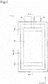
- the upper exterior member 16 and the lower exterior member 17 are each formed into a rectangular shape when viewed from the lamination direction (z-direction in FIG 1 ) of the electrode plates laminated in the power generation element 18.
- the abutting part 161 has an abutting surface that abuts against a main surface (surface parallel to the lamination surface of the electrode plates laminated in the power generation element 18: xy-plane in FIG 1 ) of the negative electrode plate 13.
- the abutting surface is parallel to a main surface of the negative electrode plate 13 located at the uppermost layer and has the same shape as that of the main surface.
- the abutting surface of the abutting part 161 corresponds to the lower surface of a lower-layer member of the abutting part 161 which is a multilayer.
- the abutting part 161 receives a pressure directly from the negative electrode plate 13.
- the abutting surface of the abutting part 161 is an area that is within the main surface of the exterior member 16 corresponding to the main surface of the negative electrode plate 13 and that receives a pressure from the power generation element 18.
- the abutting surface receives a pressure as the reaction force from the power generation element 18 in a state in which the exterior members 16 and 17 seal the power generation element 18.
- the abutting surface otherwise receives a pressure from the power generation element 18 when the power generation element 18 expands due to the use of battery.
- the sealing parts 163 and 165 are in close contact with the sealing parts 173 and 175, respectively, of the exterior member 17 while overlapping them.
- the sealing parts 163 and 165 are located at the outer circumference of the exterior member 16.
- the sealing parts 163 and 165 are configured to surround the power generation element 18 in a plan view of the exterior member 16 when viewed from the z-direction.
- the sealing parts 163 and 165 are located outside the abutting part 161 via the extending parts 162 and 164 in a plan view of the exterior member 16 when viewed from the z-direction.
- the sealing parts 163 and 165 are located at positions between the abutting part 161 and the abutting part 171 with respect to the height in the lamination direction (z-direction) of electrode plates of the power generation element 18. In other words, the sealing parts 163 and 165 are located at lower positions than a position of the abutting part 161 with respect to the height in the lamination direction (z-direction). In the example of FIG 2 , the sealing parts 163 and 165 are located at the middle position between the abutting part 161 and the abutting part 171 with respect to the height in the lamination direction (z-direction).
- the sealing parts 163 and 165 illustrated in FIG 2 are located at both ends of the exterior member 16, which is formed in a rectangular shape, along the long sides.
- another pair of sealing parts like the sealing parts 163 and 165 is formed at both end positions of the exterior member 16 along the short sides.
- the extending part 162 is a part in which the exterior member 16 extends from the abutting part 161 to the sealing part 163.
- the extending part 162 is a member for forming a space between the laminate-type power generation element 18 and the sealing parts 163 and 173 (side surfaces of the exterior members 16 and 17).
- the extending part 162 has a flat part 162a and an inclined part 162b.
- the flat part 162a is formed with a surface parallel to the abutting surface of the abutting part 161.
- the inclined part 162b is formed with a surface inclined with respect to the parallel surface to the flat part 162a.
- the exterior member 16 extends along the abutting surface of the abutting part 161 thereby to form the flat part 162a and the exterior member 16 is curved at the outer edge of the flat part 162a to extend toward the sealing part 163 thereby to form the inclined part 162b.
- the flat part 162a functions as a margin when forming the space between the laminate-type power generation element and the sealing parts 163 and 173 (side surfaces of the exterior members 16 and 17). Providing the flat part 162a allows the space to extend in the direction (x-direction or y-direction) along the lamination surface of the electrodes.
- the extending part 164 is a part in which the exterior member 16 extends from the abutting part 161 to the sealing part 165.
- the extending part 164 has a flat part 164a and an inclined part 164b.
- the extending part 164, flat part 164a, and inclined part 164b are configured in similar manners to those for the above-described extending part 162, flat part 162a, and inclined part 162b, respectively, and the description will therefore be omitted.
- the exterior member 17 is a member that seals the power generation element 18 and the electrolyte from the opposite side to the exterior member 16.
- the exterior member 17 is configured in a similar manner to that for the exterior member 16, and the description will therefore be omitted.
- the abutting part 171 is configured in a similar manner to that for the abutting part 161
- the extending parts 172 and 174 are configured in similar manners to those for the extending parts 162 and 164
- the sealing parts 173 and 175 are configured in similar manners to those for the sealing parts 163 and 165. This allows the exterior members 16 and 17 to be configured in a form of a pair of cups.
- the upper exterior member 16 and the lower exterior member 17 each have a three-layer structure in which an interior layer, an intermediate layer, and an exterior layer are arranged in this order from the inside to the outside of the secondary battery 1.
- the interior layer is composed of a film of resin, such as polyethylene, modified polyethylene, polypropylene, modified polypropylene, and ionomer, which is excellent in the electrolyte solution resistance and thermal adhesiveness.
- the intermediate layer is composed, for example, of metal foil such as aluminum foil.
- the exterior layer is composed of a film of resin, such as polyamide-based resin and polyester-based resin, which is excellent in the electrical insulation.
- the upper exterior member 16 and the lower exterior member 17 are formed of a material having flexibility, such as a resin-metal thin film laminate material.
- This flexible material is configured, for example, such that one surface (at the side of interior surface of the secondary battery 1) of metal foil such as aluminum foil is laminated with a resin and the other surface (at the side of exterior surface of the secondary battery 1) is laminated with another resin.
- the resin used for the one surface include polyethylene, modified polyethylene, polypropylene, modified polypropylene, and ionomer.
- the resin used for the other surface include polyamide-based resin and polyester-based resin.
- the exterior members 16 and 17 are each provided with a metal layer in addition to resin layers in the above manner, it is possible to enhance the strength of the exterior member itself.
- the interior layers of the exterior members 16 and 17 are composed, for example, of a resin such as polyethylene, modified polyethylene, polypropylene, modified polypropylene, and ionomer, it is possible to ensure the excellent thermal adhesiveness with the metallic electrode terminals 14 and 15.
- the positive electrode terminal 14 is led out from one end part of the sealed exterior members 16 and 17 while the negative electrode terminal 15 is led out from the other end part. Accordingly, a gap corresponding to the thickness of the electrode terminals 14 and 15 is generated in the thermal adhesion part between the upper exterior member 16 and the lower exterior member 17.
- a sealing film composed of an appropriate material such as polyethylene and polypropylene, for example, may be interposed between the electrode terminals 14 and 15 and the exterior members 16 and/or 17.
- This sealing film may preferably be composed of the same series of resin as the resin that constitutes the exterior members 16 and 17 for both the positive electrode terminal 14 and the negative electrode terminal 15 in view of the thermal adhesiveness.
- the liquid electrolyte may be obtained by dissolving a solute of lithium salt, such as lithium perchlorate, lithium borofluoride, and lithium hexafluorophosphate, in an organic liquid solvent.
- organic liquid solvent examples include ester-based solvent such as propylene carbonate (PC), ethylene carbonate (EC), dimethyl carbonate (DMC), diethyl carbonate (DEC) and ethyl methyl carbonate (EMC), and those in which an additive such as vinylene carbonate (VC), fluoroethylene carbonate (FEC) and propane sultone (PS) is added to the above solvent.
- ester-based solvent such as propylene carbonate (PC), ethylene carbonate (EC), dimethyl carbonate (DMC), diethyl carbonate (DEC) and ethyl methyl carbonate (EMC)
- an additive such as vinylene carbonate (VC), fluoroethylene carbonate (FEC) and propane sultone (PS) is added to the above solvent.
- the organic liquid solvent in one or more embodiments of the present invention is not limited to the above, and there can also be used an organic liquid solvent in which ether-based solvent such as ⁇ -butyrolactone ( ⁇ -BL) and die
- the volumetric energy density and rated discharge capacity of the secondary battery 1 will be described.
- market requirements for the traveling distance (cruisable distance) per charge may be several hundred kilometers.
- the volumetric energy density of the secondary battery 1 may preferably be 157 Wh/L or more, and the rated capacity may preferably be 20 Wh or more.
- the largeness of battery is defined from the relation of battery surface area and battery capacity as an aspect of the large battery different from an aspect of the physical largeness of electrodes.
- the secondary battery 1 is a flat laminate-type battery, in which the value of a ratio of the battery surface area (projected area of the battery including the battery exterior body) to the rated discharge capacity is 5 cm 2 /Ah or more and the rated discharge capacity is 3 Ah or more.
- the cycle characteristic tends to decrease due to the occurrence of a local overcharge mode in association with the variation of voltage in the electrode surfaces as described above.
- the aspect ratio of the lamination surface of the rectangular electrodes is preferably 1 to 3 and more preferably 1 to 2.
- the aspect ratio of an electrode is defined as a ratio of the length of long side to the length of short side of a rectangular positive electrode active material layer. When the aspect ratio falls within such a range, both the required performance for vehicle and the mounting space can be advantageously satisfied.
- FIG. 3 is a set of cross-sectional views of the secondary battery in which (a) illustrates an enlarged extra space in an initial state and (b) illustrates an enlarged extra space after the electrodes expand.
- the extra space is a space formed between the laminate-type power generation element 18 and the side surfaces (corresponding to the extending parts 162, 164, 172, and 174) of the exterior members 16 and 17.
- the thickness of the power generation element 18 is do and the length of the flat part 162a is a 0 .
- the thickness do of the power generation element 18 is half the thickness of the entire power generation element 18.
- the thickness do of the power generation element 18 refers to a thickness from the electrode plate located at the height of the sealing parts 163 and 173 in the lamination direction (z-direction) to the electrode located at the uppermost layer.
- the length of the flat part 162a refers to the length of a flat portion in the direction (x-direction) along the plane which is a surface parallel to the abutting surface of the abutting part 161.
- the power generation element 18 expands in the z-direction, so that the thickness of the power generation element 18 varies from do to d 1 (>d 0 ).
- the width in the x-direction of the power generation element 18 decreases in accordance with the expansion in the z-direction. That is, the power generation element 18 contracts in the x-direction while expanding in the z-direction.
- the extending part 162 of the exterior member 16 deforms in accordance with the expansion in the z-direction of the power generation element 18. During this deformation, the flat part 162a is drawn due to the expansion in the z-direction of the power generation element 18, and the length of the flat part 162a decreases from a 0 to a 1 ( ⁇ a 0 ).
- the exterior member 16 is formed with the flat part 162a so as to extend the extra space. This can relax the stress applied to a part abutting against the power generation element 18, to the sealing part 163 and the like when the power generation element 18 expands. Therefore, even when the exterior member 16 deforms, the pressure applied to the power generation element 18 is suppressed from being ununiform, the cell reaction can be uniform, and the durability of the cell is improved.
- a larger volume of the extra space may be advantageous in order to relax the stress when the power generation element expands. If the extra space is excessively large, however, the electrolyte solution is likely to stay in the extra space to impair the uniformity of electrolyte solution in the secondary battery 1 (liquid shortage). Therefore, an upper limit of the volume of extra space may have to be set to increase the space efficiency.
- the relationship among the length (L) of the extending part 162, the length (b) from the electrode plates to the sealing part 163 (173), and the thickness (d) of the power generation element 18 is defined to satisfy Expression (2) below.
- FIG 4 is a set of views for explaining the lengths a, b, and L and the thickness d included in the above Expression (2) and Expressions (3) and (4) below.
- (a) is a plan view of the secondary battery 1 and (b) is a cross-sectional view when cutting the secondary battery 1 at the xz-plane.
- b represents a length from the electrode plate (positive electrode plate 11 in FIG 2 ) located between the sealing parts 163 and 173 and the sealing parts 165 and 175 to the sealing parts 163 and 173. Otherwise, b represents a length from that electrode plate to the sealing parts 165 and 175.
- L represents the length of the extending part 162, which is the total length of the length of the flat part 162a and the length of the inclined part 162b.
- b represents a length from the electrode plate (negative electrode plate 13 in FIG 2 ) located at a position corresponding to a position between a pair of the sealing parts to one sealing part of the pair of the sealing parts.
- L represents the length of the extending part.
- Parameter d represents the thickness of the power generation element 18, which refers to a thickness from the specified electrode plate to the electrode plate located at the uppermost layer or a thickness from the specified electrode plate to the electrode plate located at the lowermost layer.
- the specified electrode plate is located at the height of the sealing parts 163 and 173 in the lamination direction (z-direction).
- L and d may preferably be defined to satisfy Expression (3) below. [Expression 3] 1.65 ⁇ L d ⁇ 1.95
- a In the cross section when cutting the secondary battery 1 at the xz-plane, a represents the length of the flat parts 162a, 164a, 172a, and 174a. In the cross section when cutting the secondary battery 1 at the yz-plane, a represents the length of the flat parts which extend from the long sides of the abutting parts 161 and 171 to the corresponding sealing parts.
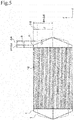
- FIG 5 is a cross-sectional view of the secondary battery 1.
- FIG 5 is a view for explaining the initial battery state and the battery state after the battery is used a certain number of times.
- the secondary battery 1 indicated by broken lines represents the battery of the initial state while the secondary battery 1 indicated by solid lines represents the battery after use.
- d represents the thickness of the power generation element 18 in the initial state and a represents the length of the flat part 162a in the initial state.
- ⁇ d represents the increase in the thickness of the power generation element 18 when the battery expands and ⁇ a represents the decrease in the length of the extending part 162 when the battery expands. That is, in the secondary battery after the battery is used a certain number of times, the thickness of the power generation element 18 is d+ ⁇ d and the length of the flat part 162a is a- ⁇ a.
- the certain number of times refers to a number of times of charging and discharging the battery, and the certain number of times is preliminarily defined in accordance with the utilization form and the like of the battery.
- the certain number of time is preliminarily defined, for example, in accordance with the expected lifetime of a secondary battery.
- the parameters may preferably be defined to satisfy Expression (5) or Expression (6) below.
- Expression 5 1.0 ⁇ d + ⁇ d d ⁇ 1.4
- Expression 6 0 ⁇ a ⁇ ⁇ a a ⁇ 1.0
- the shape of the exterior members 16 and 17 may be configured such that the length of the flat part 162a decreases as the thickness d of the power generation element increases due to the use of the secondary battery 1.
- This allows the secondary battery 1 to have a defined margin of the extra volume with respect to the thickness of the power generation element 18 which expands after the use of a certain number of times. Therefore, when the power generation element 18 expands, the stress applied to a part abutting against the power generation element 18, the stress applied to the sealing part 163 and the like can be relaxed.
- one or more embodiments of the present invention can prevent the capacity drop due to liquid shortage and the like because the efficiency of the extra space can be enhanced.
- a- ⁇ a corresponds to the length of the x-direction component of a length, in the xy-plane (cross section), from the abutting parts 161 and 171 (ends of the abutting parts 161 and 171) to the curved points (corresponding to the point P of FIG 5 ).
- the thickness d of the power generation element increases due to the use of the secondary battery 1, the length from the abutting parts 161 and 172 to the curved points decreases.
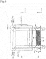
- FIG 6 is a set of views for explaining the lengths a, b, and L and the thickness d included in the above Expression (2) to Expression (6).
- (a) is a plan view of a secondary battery 1 according to Modified Example 1 and (b) is a cross-sectional view when cutting the secondary battery 1 according to Modified Example 1 at the xz-plane.
- an exterior member 17 is formed as a plate and the main surface of the exterior member 17 is parallel to the lamination surface of electrode plates of a power generation element 18.
- the interior side of the main surface abuts against the lowermost electrode plate of electrode plates that constitute the power generation element 18.
- the outer circumference of the main surface is formed with sealing parts 173 and 175 that overlap sealing parts 163 and 165 of an exterior member 16.
- the sealing parts 173 and 175 are in close contact with the sealing parts 163 and 165, respectively.
- the length (L) of the extending parts 162 and 164 and the thickness of the power generation element 18 are the same as those of the secondary battery 1 illustrated in FIG 4 .
- the length (b) represents a length from the lowermost electrode plate located between the sealing parts 163 and 173 and the sealing parts 165 and 175 to the sealing parts 163, 165, 173, and 175.
- the electrode plate located between the sealing parts 163 and 173 and the sealing parts 165 and 175 is the electrode plate of the lowermost layer (negative electrode plate in FIG 5 ) of the power generation element 18.
- FIG 7 is a cross-sectional view of the secondary battery 1 according to Modified Example 1
- FIG. 7 is a view for explaining the initial battery state and the battery state after the battery is used a certain number of times.
- the secondary battery 1 indicated by broken lines represents the battery of the initial state while the secondary battery 1 indicated by solid lines represents the battery after use.
- the parameters a, ⁇ a, d, and ⁇ d according to Modified Example 1 are the same as the above parameters a, ⁇ a, d, and ⁇ d as described using FIG 5 , and the description will therefore be omitted.
- FIG 8 is a set of views for explaining the lengths a, b, and L and the thickness d included in the above Expressions (2) to (4).
- (a) is a plan view of a secondary battery 1 according to Modified Example 2
- (b) is a cross-sectional view when cutting the secondary battery 1 according to Modified Example 2 at the xz-plane.
- an upper exterior member 16 has an abutting part 161, an extending part 162, an extending part 164, a sealing part 163, and a sealing part 165.
- a lower exterior member 17 has an abutting part 171, an extending part 172, an extending part 174, a sealing part 173, and a sealing part 175.
- the abutting parts 161 and 171 are similar to the abutting parts 161 and 171 according to one or more embodiments of the present invention
- the sealing parts 163, 165, 173, and 175 are similar to the sealing parts 163, 165, 173, and 175 according to one or more embodiments of the present invention, and the description of the structures will therefore be omitted.
- the extending part 162 has a flat part 162a and a curved part 162c.
- the flat part 162a is similar to the flat part 162a according to one or more embodiments of the present invention.
- the curved part 162c is curved from the outer edge of the flat part 162a and extends to the sealing part 163. In the cross section when cutting the secondary battery 1 at the xz-plane, the curved part 162c is formed to be a curve so as to expand from the inside of the secondary battery 1 to the outside, as illustrated in FIG 8(b) .
- the extending part 164 has a flat part 164a and a curved part 164c.
- the structures of the flat part 164a and curved part 164c are similar to those of the flat part 162a and curved part 162c, and the description will therefore be omitted.
- the exterior member 17 has a shape in which parts of the extending parts 172 and 174 are curved, and seals the power generation element 18 from the opposite side to the exterior member 16.
- the abutting part 171, flat parts 172a and 174a, curved parts 172c and 174c, and sealing parts 173 and 175, which constitute the exterior member 17, are similar to the abutting part 161, flat parts 162a and 164a, curved parts 162c and 164c, and sealing parts 163 and 165, which constitute the exterior member 16, and the description will therefore be omitted.
- the length (L) of the extending parts 162 and 164 is the total length of the length of the flat parts 162a and 164a and the length of the curved parts 162c and 164c.
- the length (L) of the extending parts 172 and 174 is the total length of the length of the flat parts 172a and 174a and the length of the curved parts 172c and 174c.
- the thickness of the power generation element 18 and the length (a) are the same as those of the secondary battery 1 illustrated in FIG 4 according to one or more embodiments of the present invention.
- a positive electrode active material slurry was prepared by mixing 90 wt% of an NMC composite oxide (LiNi 0.5 Mn 0.3 Co 0.2 O 2 (average particle diameter: 10 ⁇ m), 5 wt% of Ketjen black as a conductive agent, 5 wt% of polyvinylidene fluoride (PVdF) as a binder, and an appropriate amount of NMP as a slurry viscosity adjusting solvent.
- the obtained positive electrode active material slurry was applied to aluminum foil (thickness of 20 ⁇ m) as a collector, dried at 120°C, and then formed by compression using a roll press machine to produce each positive electrode plate 11 with a positive electrode active material layer of 18 mg/cm 2 .
- Another positive electrode active material layer was also formed on the rear surface in the same manner, and the positive electrode plate 11 formed with the positive electrode active material layers on both surfaces of the positive electrode collector was thus produced.
- the size of the main surface of the positive electrode plate 11 the length was 215 mm and the width was 190 mm.
- a negative electrode active material slurry was prepared by dispersing 96.5 wt% of synthetic graphite as a negative electrode active material and 1.5 wt% of ammonium salt of carboxymethyl cellulose and 2.0 wt% of styrene-butadiene copolymer latex as binders in purified water.
- This negative electrode active material slurry was applied to copper foil (thickness of 10 ⁇ m) as a negative electrode collector, dried at 120°C, and then formed by compression using a roll press machine to produce each negative electrode plate 13 with a negative electrode active material layer of 10 mg/cm 2 .
- Another negative electrode active material layer was also formed on the rear surface in the same manner, and the negative electrode plate 13 formed with the negative electrode active material layers on both surfaces of the negative electrode collector was thus produced.
- the size of the main surface of the negative electrode plate 13 the length was 219 mm and the width was 194 mm.
- the positive electrodes produced in the above and the negative electrodes produced in the above were alternately laminated (20 layers of positive electrodes and 21 layers of negative electrodes) via separators to produce a power generation element 18.
- the size of the separators the length was 223 mm and the width was 198 mm.
- the obtained power generation element 18 was placed in an aluminum laminate sheet bag and an electrolyte solution was injected therein.
- the electrolyte solution used was prepared by dissolving 1.0 M of LiPF6 in a mixed solvent of ethylene carbonate (EC), diethyl carbonate (DEC), and ethyl methyl carbonate (EMC) (volume ratio of 1:1:1).
- EC ethylene carbonate
- DEC diethyl carbonate
- EMC ethyl methyl carbonate
- the outer length in the x-direction (x 4 in FIG 4 ) was 250 mm
- the outer length in the y-direction (y 4 in FIG 4 ) was 210 mm
- the height in the z-direction was 4 mm
- the length in the x-direction (x 3 in FIG 4 ) was 225 mm
- the length in the y-direction (y 3 in FIG 4 ) was 200 mm.
- the size of interior space corresponds to the size of a portion of the exterior member 16 except the sealing part.
- the length in the x-direction (x 2 in FIG 4 ) was 221 mm and the length in the y-direction (y 2 in FIG 4 ) was 196 mm.
- the size of the exterior member 17 was the same as the size of the exterior member 16.
- the length in the x-direction (x 1 in FIG 4 ) was 215 mm
- the length in the y-direction (y 1 in FIG 4 ) was 190 mm
- the length in the z-direction (length twice d of FIG 4 ) was 8 mm.
- the length in the x-direction of the secondary battery 1 including the electrode terminals 14 and 15 was 280 mm, the length in the y-direction (width) was 210 mm, and the length in the z-direction (thickness) was 8 mm.
- 1C_CCCV charge upper limit voltage of 4.15 V, 2 hours
- 1C_CC discharge lower limit voltage of 2.5 V cut
- the charge and discharge capacity of the secondary battery 1 was confirmed and the secondary battery 1 was evaluated by calculating the capacity retention ratio to the initial charge and discharge capacity ((charge and discharge capacity after charge and discharge were performed 1,000 cycles)/(initial charge and discharge capacity) ⁇ 100%).
- Example 1 is the secondary battery 1 produced as the above.
- the length in the x-direction (x 2 in FIG 4 ) was 219 mm and the length in the y-direction (y 2 in FIG. 4 ) was 194 mm.
- Other sizes and the number of layers of the electrodes are the same as those in Example 1.
- the length in the x-direction (x 2 in FIG 4 ) was 217 mm and the length in the y-direction (y 2 in FIG. 4 ) was 192 mm.
- Other sizes and the number of layers of the electrodes are the same as those in Example 1.
- the length in the x-direction (x 2 in FIG 4 ) was 222 mm and the length in the y-direction (y 2 in FIG. 4 ) was 197 mm.
- Other sizes and the number of layers of the electrodes are the same as those in Example 1.
- the outer length in the x-direction (x 4 in FIG 4 ) was 250 mm
- the outer length in the y-direction (y 4 in FIG 4 ) was 210 mm
- the height in the z-direction was 4.5 mm
- the length in the x-direction (x 2 in FIG 4 ) was 221 mm
- the length in the y-direction (y 2 in FIG. 4 ) was 196 mm.
- Other sizes are the same as those in Example 1.
- the outer length in the x-direction (x 4 in FIG 4 ) was 250 mm
- the outer length in the y-direction (y 4 in FIG 4 ) was 210 mm
- the height in the z-direction was 5 mm
- the length in the x-direction (x 2 in FIG 4 ) was 221 mm
- the length in the y-direction (y 2 in FIG 4 ) was 196 mm.
- Other sizes are the same as those in Example 1.
- the electrode plates 16 layers of positive electrodes and 17 layers of negative electrodes were used as the electrode plates.
- the outer length in the x-direction (x 4 in FIG 4 ) was 250 mm
- the outer length in the y-direction (y 4 in FIG. 4 ) was 210 mm
- the height in the z-direction was 3.0 mm
- the length in the x-direction (x 2 in FIG 4 ) was 221 mm
- the length in the y-direction (y 2 in FIG 4 ) was 196 mm.
- Other sizes are the same as those in Example 1.
- the length in the x-direction (x 2 in FIG 4 ) was 215 mm and the length in the y-direction (y 2 in FIG 4 ) was 190 mm.
- Other sizes and the number of layers of the electrodes are the same as those in Example 1.
- the length in the x-direction (x 2 in FIG 4 ) was 216 mm and the length in the y-direction (y 2 in FIG 4 ) was 191 mm.
- Other sizes and the number of layers of the electrodes are the same as those in Example 1.
- the length in the x-direction (x 2 in FIG 4 ) was 223 mm and the length in the y-direction (y 2 in FIG 4 ) was 198 mm.
- Other sizes and the number of layers of the electrodes are the same as those in Example 1.
- the length in the x-direction (x 2 in FIG 4 ) was 225 mm and the length in the y-direction (y 2 in FIG 4 ) was 200 mm.
- Other sizes and the number of layers of the electrodes are the same as those in Example 1.
- the electrode plates 16 layers of positive electrodes and 17 layers of negative electrodes were used as the electrode plates.
- the outer length in the x-direction (x 4 in FIG 4 ) was 250 mm
- the outer length in the y-direction (y 4 in FIG 4 ) was 210 mm
- the height in the z-direction was 3.0 mm
- the length in the x-direction (x 2 in FIG 4 ) was 216 mm
- the length in the y-direction (y 2 in FIG 4 ) was 191 mm.
- Other sizes are the same as those in Example 1.
- the outer length in the x-direction (x 4 in FIG. 4 ) was 250 mm
- the outer length in the y-direction (y 4 in FIG. 4 ) was 210 mm
- the height in the z-direction was 5.0 mm
- the length in the x-direction (x 2 in FIG 4 ) was 216 mm
- the length in the y-direction (y 2 in FIG 4 ) was 191 mm.
- Other sizes are the same as those in Example 1.
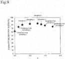
- FIGS. 9 to 16 are graphs representing the relationships of the capacity retention ratio to the parameters (a, a/d, L/d, L/ ⁇ (b 2 +d 2 ), and d).
- FIG 9 is a graph representing the relationship of the capacity retention ratio to the parameter (a)
- FIG 13 is a graph representing the relationship of the capacity retention ratio to the parameter (d)
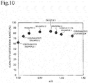
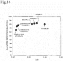
- FIGS. 10 and 14 are graphs each representing the relationship of the capacity retention ratio to the parameter (a/d)
- FIGS. 11 and 15 are graphs each representing the relationship of the capacity retention ratio to the parameter (L/d)
- FIGS. 12 and 16 are graphs each representing the relationship of the capacity retention ratio to the parameter (L/ ⁇ (b 2 +d 2 )).
- a high capacity retention ratio (capacity retention ratio of 80% or more) can be obtained even after the use of 1,000 cycles.
- a high capacity retention ratio (capacity retention ratio of 80% or more) can be obtained after the use of 1,000 cycles.
- a high capacity retention ratio (capacity retention ratio of 80% or more) can be obtained after the use of 1,000 cycles.
- a high capacity retention ratio (capacity retention ratio of 80% or more) can be obtained after the use of 1,000 cycles.
- a high capacity retention ratio (capacity retention ratio of 80% or more) can be obtained after the use of 1,000 cycles.
- a high capacity retention ratio (capacity retention ratio of 80% or more) can be obtained after the use of 1,000 cycles.
- the parameters of Example 7 fall outside Expression (3) and Expression (4), but satisfy Expression (2) thereby to allow a high capacity retention ratio (capacity retention ratio of 80% or more) to be obtained.
- the secondary batteries 1 (Comparative Examples 1 to 6) in which the parameters b, d, and L do not satisfy Expression (2) exhibit results of a poor capacity retention ratio after the use of 1,000 cycles.
- the secondary batteries 1 (Comparative Examples 1 to 6) in which the parameters L, a, and d do not satisfy Expression (3) or Expression (4) exhibit results of a poor capacity retention ratio after the use of 1,000 cycles.
- the above flat parts 162a, 164a, 172a, and 174a correspond to the "first extending part" of the present invention
- the inclined parts 162b, 164b, 172b, and 174b correspond to the "second extending part" of the present invention.
Landscapes
- Chemical & Material Sciences (AREA)
- Electrochemistry (AREA)
- General Chemical & Material Sciences (AREA)
- Chemical Kinetics & Catalysis (AREA)
- Engineering & Computer Science (AREA)
- Manufacturing & Machinery (AREA)
- Inorganic Chemistry (AREA)
- Materials Engineering (AREA)
- Physics & Mathematics (AREA)
- Condensed Matter Physics & Semiconductors (AREA)
- General Physics & Mathematics (AREA)
- Sealing Battery Cases Or Jackets (AREA)
- Secondary Cells (AREA)
- Battery Electrode And Active Subsutance (AREA)
Abstract

wherein, in a cross section of the flat secondary battery when cutting through the flat secondary battery by a plane parallel to sides that form the rectangular exterior members and along the lamination direction,
the L represents a length of the extending part,
the b represents a length from an inter-sealing part electrode of the two or more electrodes to the sealing parts, the inter-sealing part electrode is located at height of the sealing part in the lamination direction, and
the d represents a thickness of the laminate-type power generation element from the inter-sealing part electrode to the uppermost layer electrode.
Description
- The present invention relates to a flat secondary battery.
- This application claims a priority on the basis of Japanese Patent Application No.
2014-82376, filed on April 11, 2014 - Paten
Document 1 discloses a nonaqueous electrolyte secondary battery comprising a flat battery element, a bag-like exterior case which houses the flat battery element, a positive electrode lead which is led out from a sealing part of the exterior case, and a negative electrode lead which is led out from the sealing part of the exterior case. The flat battery element is configured such that sheet-like or film-like positive electrode plates, separators for holding electrolyte, and negative electrode plates are laminated. One end of the positive electrode lead is connected to the positive electrode plates and one end of the negative electrode lead is connected to the negative electrode plates. - [Patent Document 1]
JP 2001-297748 A - In the above secondary battery, however, the interior space of the battery formed between the power generation element and the case is not taken into account. Therefore, when the charge and discharge are repeated and accordingly the electrodes expand in the thickness direction to deform the case, the pressure applied from the laminate exterior case to the power generation element becomes ununiform to lead to ununiform cell reaction and poor durability of the cell.
- Problems to be solved by the present invention include providing a flat secondary battery in which the pressure applied from the laminate exterior case to the power generation element is suppressed from being ununiform and the durability of the cell can be improved when the charge and discharge are repeated and accordingly the electrodes expand in the thickness direction.
- The present invention solves the above problem as follows. A flat secondary battery comprises: a laminate-type power generation element; and a pair of exterior members that are formed into a rectangular shape when viewed from a lamination direction of electrodes while sealing the laminate-type power generation element and an electrolyte solution. The exterior member comprises an abutting part including an abutting surface that abuts against an uppermost layer electrode, a sealing part at which the exterior members overlap each other at an outer circumferential position of the exterior members, and an extending part that extends from the abutting part to the sealing part. The relationship among the length (L), the length (b), and the thickness (d) satisfies Expression (1) below. The length (L) represents a length of the extending part, the length (b) represents a length from an electrode located at height of the sealing part in the lamination direction between the sealing parts to the sealing parts, and the thickness (d) represents a length of the laminate-type power generation element.
[Expression 1]
- According to the present invention, when the charge and discharge are repeated to expand the electrodes in the thickness direction, the stress applied to the sealing part of the laminate exterior case and the like can be relaxed. Therefore, even when the case deforms, the pressure applied to the power generation element can be uniform. This can result in suppression of deterioration progression in the battery.
-
- [
Fig. 1] FIG 1 is a plan view of a secondary battery according to one or more embodiments of the present invention. - [
Fig. 2] FIG 2 is a cross-sectional view along line II-II ofFIG 1 . - [
Fig. 3] FIG 3 is a set of cross-sectional views of the secondary battery ofFIG 1 in which (a) illustrates an enlarged extra space in an initial state and (b) illustrates an enlarged extra space after the electrodes expand. - [
Fig. 4 ] InFIG 4 , (a) is a plan view of the secondary battery according to one or more embodiments of the present invention and (b) is a cross-sectional view when cutting the secondary battery of (a) at the xz-plane. - [
Fig. 5] FIG. 5 is a cross-sectional view of the secondary battery according to one or more embodiments of the present invention. - [
Fig. 6 ] InFIG 6 , (a) is a plan view of a secondary battery according to a modified example of one or more embodiments of the present invention and (b) is a cross-sectional view when cutting the secondary battery of (a) at the xz-plane. - [
Fig. 7] FIG 7 is a cross-sectional view of the secondary battery according to the modified example of one or more embodiments of the present invention. - [
Fig. 8 ] InFIG 8 , (a) is a plan view of a secondary battery according to another modified example of one or more embodiments of the present invention and (b) is a cross-sectional view when cutting the secondary battery of (a) at the xz-plane. - [
Fig. 9] FIG 9 is a graph illustrating the capacity retention ratio to the parameter (a) in the secondary batteries according to Examples 1 to 4 and Comparative Examples 1 to 4. - [
Fig. 10] FIG 10 is a graph illustrating the capacity retention ratio to the parameter (a/d) in the secondary batteries according to Examples 1 to 4 and Comparative Examples 1 to 4. - [
Fig. 11] FIG 11 is a graph illustrating the capacity retention ratio to the parameter (L/d) in the secondary batteries according to Examples 1 to 4 and Comparative Examples 1 to 4. - [
Fig. 12] FIG 12 is a graph illustrating the capacity retention ratio to the parameter (L/√(b2+d2)) in the secondary batteries according to Examples 1 to 4 and Comparative Examples 1 to 4. - [
Fig. 13] FIG 13 is a graph illustrating the capacity retention ratio to the parameter (d) in the secondary batteries according to Examples 1, 6, and 7 and Comparative Examples 2, 5, and 6. - [
Fig. 14] FIG 14 is a graph illustrating the capacity retention ratio to the parameter (a/d) in the secondary batteries according to Examples 1 and 5 to 7 and Comparative Examples 2, 5, and 6. - [
Fig. 15] FIG 15 is a graph illustrating the capacity retention ratio to the parameter (L/d) in the secondary batteries according to Examples 1 and 5 to 7 and Comparative Examples 2, 5, and 6. - [
Fig. 16] FIG 16 is a graph illustrating the capacity retention ratio to the parameter (L/√(b2+d2)) in the secondary batteries according to Examples 1 and 5 to 7 and Comparative Examples 2, 5, and 6. - Hereinafter, one or more embodiments of the present invention will be described with reference to the drawings.
-
Secondary battery 1 according to one or more embodiments of the present invention is a lithium-based, plate-like, laminate-type flat (thin) battery. Thesecondary battery 1 is composed of fivepositive electrode plates 11, tenseparators 12, sixnegative electrode plates 13, apositive electrode terminal 14, anegative electrode terminal 15, an upperexterior member 16, a lowerexterior member 17, and an electrolyte which is not particularly illustrated, as illustrated inFIG 1 andFIG 2 . The numbers of thepositive electrode plates 11,separators 12, andnegative electrode plates 13 are merely exemplified and other numbers thereof may also be employed. - The
positive electrode plates 11,separators 12, andnegative electrode plates 13 constitute apower generation element 18. Thepositive electrode plates 11 andnegative electrode plates 13 constitute electrode plates. Theupper exterior member 16 andlower exterior member 17 constitute a pair of exterior members. - Each of the
positive electrode plates 11 which constitute thepower generation element 18 has a positive electrode-side collector 11a that extends to thepositive electrode terminal 14 andpositive electrode layers side collector 11a. Thepositive electrode layers positive electrode plate 11 at which thepositive electrode plate 11 substantially overlaps theseparators 12 when thepositive electrode plates 11,separators 12, andnegative electrode plates 13 are laminated to constitute thepower generation element 18. In one or more embodiments of the present invention, thepositive electrode plate 11 and the positive electrode-side collector 11a are formed of one conductor, but thepositive electrode plate 11 and the positive electrode-side collector 11a may be configured as separate components and then bonded with each other. - The positive electrode-
side collector 11a of thepositive electrode plate 11 is composed of aluminum foil. The positive electrode-side collector 11a may also be composed of electrochemically stable metal foil, such as aluminum alloy foil, copper foil, and nickel foil. Thepositive electrode layers positive electrode plate 11 contain a lithium-nickel-manganese-cobalt composite oxide (referred also to as an "NMC composite oxide," hereinafter) as the positive electrode active material. The NMC composite oxide has a layered crystal structure in which lithium atom layers and transition metal atom layers (of Mn, Ni, and Co that are orderly arranged) are stacked alternately via oxygen atom layers and one Li atom is included in terms of one atom of transition metal M so as to increase an amount of extractable Li and high capacity. The positive electrode active material may also be a lithium composite oxide, such as lithium nickelate (LiNiO2), lithium manganate (LiMnO2), and lithium cobaltate (LiCoO2). The positive electrode active material may also be a combination of the above lithium composite oxides. - The
positive electrode layers side collector 11a, and drying and flatting the mixture. The conductive agent may be a carbon black such as Ketjen black and acetylene black. The binde may be aqueous dispersion of polyvinylidene fluoride (PVdF) and/or polytetrafluoroethylene (PTFE). The slurry viscosity adjusting solvent is N-methyl-2-pyrrolidone (NMP) or the like. - Each of the
negative electrode plates 13 which constitute thepower generation element 18 has a negative electrode-side collector 13a that extends to thenegative electrode terminal 15 andnegative electrode layers side collector 13a. Similar to the positive electrode side, thenegative electrode layers negative electrode plate 13 may also be formed only on areas of eachnegative electrode plate 13 at which thenegative electrode plate 13 substantially overlaps theseparators 12. In one or more embodiments of the present invention, thenegative electrode plate 13 and the negative electrode-side collector 13a are formed of one conductor, but thenegative electrode plate 13 and the negative electrode-side collector 13a may be configured as separate components and then bonded with each other. - The negative electrode-
side collector 13a of thenegative electrode plate 13 is composed of copper foil. The negative electrode-side collector 13a may also be composed of electrochemically stable metal foil, such as nickel foil, stainless steel foil, and iron foil. The negative electrode layers 13b and 13c of thenegative electrode plate 13 contain synthetic graphite as the negative electrode active material. The negative electrode active material may be material which absorb and release lithium ions, such as Si alloy, mixture of graphite and Si, amorphous carbon, non-graphitizable carbon, graphitizable carbon, and graphite. - The negative electrode layers 13b and 13c are formed by preparing a negative electrode active material that contains synthetic graphite while containing ammonium salt of carboxymethyl cellulose and styrene-butadiene copolymer latex as binders, dispersing the negative electrode active material in purified water to obtain a negative electrode active material slurry, applying the slurry to both main surfaces of the negative electrode-
side collector 13a, and drying and flatting the slurry. The negative electrode active material slurry to be used may also be obtained by dispersing PVdF as a binder in NMP. - The
separators 12 of thepower generation element 18 are to prevent short circuit between the above-describedpositive electrode plates 11 andnegative electrode plates 13, and theseparators 12 may have a function of holding an electrolyte. Eachseparator 12 is a microporous membrane that is composed, for example, of polyolefin such as polyethylene (PE) and polypropylene (PP), and has a function of shutting off an excessive current so that the heat generated by the excessive current blocks the pores. - The
separator 12 used in one or more embodiments of the present invention is not limited only to a single-layer membrane. Theseparator 12 may be formed by a membrane of a three-layer structure in which a polypropylene membrane is sandwiched by polyethylene membranes. Theseparator 12 may be formed by a membrane configured such that a polyolefin microporous membrane, an organic nonwoven fabric and the like are laminated. Theseparator 12 may be a separator having a heat-resistant and insulating layer (ceramic layer) at the surface (so-called ceramic separator). Making theseparator 12 as a multilayer in such a manner can give various functions, such as a function of preventing an excessive current, a function of holding an electrolyte, and a function of maintaining the shape of the separator (enhancing the stiffness), to the separator. - The above
power generation element 18 is configured as a laminate-type power generation element in which thepositive electrode plates 11 and thenegative electrode plates 13 are laminated alternately via each of the separators 12(Thepower generation elements 18 includes pairs of electrodes laminated via aseparator 12, each of the pairs of the electrodes having which two or more plate-like electrodes are laminated via each of separators.). The fivepositive electrode plates 11 are connected to thepositive electrode terminal 14 of metal foil via the positive electrode-side collectors 11a while the sixnegative electrode plates 13 are connected to thenegative electrode terminal 15 of metal foil via the negative electrode-side collectors 13a in a similar manner. - The
positive electrode terminal 14 and thenegative electrode terminal 15 are not particularly limited, provided that they are made of electrochemically stable metal material. Examples of thepositive electrode terminal 14 include, as in the above-described positive electrode-side collector 11a, aluminum foil, aluminum alloy foil, copper foil, and nickel foil which have, for example, a thickness of about 0.2 mm. Examples of thenegative electrode terminal 15 include, as in the above-described negative electrode-side collector 13a, nickel foil, copper foil, stainless steel foil, and iron foil which have, for example, a thickness of about 0.2 mm. - In one or more embodiments of the present invention, the
electrode plates electrode terminals collectors electrode terminal positive electrode layer negative electrode layer collector collector - The
upper exterior member 16 and thelower exterior member 17 house and seal thepower generation element 18 together with an electrolyte. As will be understood, the power generation element may be a part of the laminated electrode plates within which the positive electrodes and the negative electrodes substantially overlap one another via the separators. Theupper exterior member 16 and thelower exterior member 17 serve as a pair of members that constitute a case for sealing thepower generation element 18 and the electrolyte solution Theupper exterior member 16 and thelower exterior member 17 are configured as below. - As illustrated in
FIG 2 , theupper exterior member 16 and thelower exterior member 17 are each formed into a cup shape. Theupper exterior member 16 has anabutting part 161, an extendingpart 162, an extendingpart 164, a sealingpart 163 and a sealingpart 165. Thelower exterior member 17 has anabutting part 171, an extendingpart 172, an extendingpart 174, a sealingpart 173 and a sealingpart 175. Theupper exterior member 16 and thelower exterior member 17 are each formed into a rectangular shape when viewed from the lamination direction (z-direction inFIG 1 ) of the electrode plates laminated in thepower generation element 18. - The
abutting part 161 has an abutting surface that abuts against a main surface (surface parallel to the lamination surface of the electrode plates laminated in the power generation element 18: xy-plane inFIG 1 ) of thenegative electrode plate 13. The abutting surface is parallel to a main surface of thenegative electrode plate 13 located at the uppermost layer and has the same shape as that of the main surface. The abutting surface of theabutting part 161 corresponds to the lower surface of a lower-layer member of theabutting part 161 which is a multilayer. When theexterior members power generation element 18, theabutting part 161 applies a pressure to thenegative electrode plate 13 located at the uppermost layer. On the other hand, when the charge and discharge are repeated and accordingly thepower generation element 18 expands in the thickness direction (z-direction inFIG 2 ), theabutting part 161 receives a pressure directly from thenegative electrode plate 13. The abutting surface of theabutting part 161 is an area that is within the main surface of theexterior member 16 corresponding to the main surface of thenegative electrode plate 13 and that receives a pressure from thepower generation element 18. The abutting surface receives a pressure as the reaction force from thepower generation element 18 in a state in which theexterior members power generation element 18. The abutting surface otherwise receives a pressure from thepower generation element 18 when thepower generation element 18 expands due to the use of battery. - The sealing
parts parts exterior member 17 while overlapping them. The sealingparts exterior member 16. The sealingparts power generation element 18 in a plan view of theexterior member 16 when viewed from the z-direction. The sealingparts abutting part 161 via the extendingparts exterior member 16 when viewed from the z-direction. The sealingparts abutting part 161 and theabutting part 171 with respect to the height in the lamination direction (z-direction) of electrode plates of thepower generation element 18. In other words, the sealingparts abutting part 161 with respect to the height in the lamination direction (z-direction). In the example ofFIG 2 , the sealingparts abutting part 161 and theabutting part 171 with respect to the height in the lamination direction (z-direction). - The sealing
parts FIG 2 are located at both ends of theexterior member 16, which is formed in a rectangular shape, along the long sides. In addition, another pair of sealing parts like the sealingparts exterior member 16 along the short sides. - The extending
part 162 is a part in which theexterior member 16 extends from theabutting part 161 to the sealingpart 163. The extendingpart 162 is a member for forming a space between the laminate-typepower generation element 18 and the sealingparts 163 and 173 (side surfaces of theexterior members 16 and 17). - The extending
part 162 has aflat part 162a and aninclined part 162b. Theflat part 162a is formed with a surface parallel to the abutting surface of theabutting part 161. Theinclined part 162b is formed with a surface inclined with respect to the parallel surface to theflat part 162a. Theexterior member 16 extends along the abutting surface of theabutting part 161 thereby to form theflat part 162a and theexterior member 16 is curved at the outer edge of theflat part 162a to extend toward the sealingpart 163 thereby to form theinclined part 162b. Theflat part 162a functions as a margin when forming the space between the laminate-type power generation element and the sealingparts 163 and 173 (side surfaces of theexterior members 16 and 17). Providing theflat part 162a allows the space to extend in the direction (x-direction or y-direction) along the lamination surface of the electrodes. - The extending
part 164 is a part in which theexterior member 16 extends from theabutting part 161 to the sealingpart 165. The extendingpart 164 has aflat part 164a and aninclined part 164b. The extendingpart 164,flat part 164a, and inclinedpart 164b are configured in similar manners to those for the above-described extendingpart 162,flat part 162a, and inclinedpart 162b, respectively, and the description will therefore be omitted. - The
exterior member 17 is a member that seals thepower generation element 18 and the electrolyte from the opposite side to theexterior member 16. Theexterior member 17 is configured in a similar manner to that for theexterior member 16, and the description will therefore be omitted. As will be understood, theabutting part 171 is configured in a similar manner to that for theabutting part 161, the extendingparts parts parts parts exterior members - Although not particularly illustrated, in one or more embodiments of the present invention, the
upper exterior member 16 and thelower exterior member 17 each have a three-layer structure in which an interior layer, an intermediate layer, and an exterior layer are arranged in this order from the inside to the outside of thesecondary battery 1. The interior layer is composed of a film of resin, such as polyethylene, modified polyethylene, polypropylene, modified polypropylene, and ionomer, which is excellent in the electrolyte solution resistance and thermal adhesiveness. The intermediate layer is composed, for example, of metal foil such as aluminum foil. The exterior layer is composed of a film of resin, such as polyamide-based resin and polyester-based resin, which is excellent in the electrical insulation. - Thus, the
upper exterior member 16 and thelower exterior member 17 are formed of a material having flexibility, such as a resin-metal thin film laminate material. This flexible material is configured, for example, such that one surface (at the side of interior surface of the secondary battery 1) of metal foil such as aluminum foil is laminated with a resin and the other surface (at the side of exterior surface of the secondary battery 1) is laminated with another resin. Examples of the resin used for the one surface include polyethylene, modified polyethylene, polypropylene, modified polypropylene, and ionomer. Examples of the resin used for the other surface include polyamide-based resin and polyester-based resin. - When the
exterior members exterior members metallic electrode terminals - As illustrated in
FIG 1 andFIG 2 , thepositive electrode terminal 14 is led out from one end part of the sealedexterior members negative electrode terminal 15 is led out from the other end part. Accordingly, a gap corresponding to the thickness of theelectrode terminals upper exterior member 16 and thelower exterior member 17. In order to maintain the sealing ability in thesecondary battery 1, a sealing film composed of an appropriate material such as polyethylene and polypropylene, for example, may be interposed between theelectrode terminals exterior members 16 and/or 17. This sealing film may preferably be composed of the same series of resin as the resin that constitutes theexterior members positive electrode terminal 14 and thenegative electrode terminal 15 in view of the thermal adhesiveness. - After the above-described
power generation element 18, a part of thepositive electrode terminal 14, and a part of thenegative electrode terminal 15 are wrapped with theexterior members exterior members exterior members - Examples of the organic liquid solvent include ester-based solvent such as propylene carbonate (PC), ethylene carbonate (EC), dimethyl carbonate (DMC), diethyl carbonate (DEC) and ethyl methyl carbonate (EMC), and those in which an additive such as vinylene carbonate (VC), fluoroethylene carbonate (FEC) and propane sultone (PS) is added to the above solvent. The organic liquid solvent in one or more embodiments of the present invention is not limited to the above, and there can also be used an organic liquid solvent in which ether-based solvent such as γ-butyrolactone (γ-BL) and diethoxy ethane (DEE) or other solvent is mixed and blended with an ester-based solvent. The organic liquid solvent may preferably contain various additives, such as vinylene carbonate (VC), fluoroethylene carbonate (FEC), and 1,3-propanesultone (PS).
- Next, the volumetric energy density and rated discharge capacity of the
secondary battery 1 will be described. In general electric cars, market requirements for the traveling distance (cruisable distance) per charge may be several hundred kilometers. In consideration of such a cruisable distance, the volumetric energy density of the secondary battery 1may preferably be 157 Wh/L or more, and the rated capacity may preferably be 20 Wh or more. - In the
secondary battery 1 according to one or more embodiments of the present invention, the largeness of battery is defined from the relation of battery surface area and battery capacity as an aspect of the large battery different from an aspect of the physical largeness of electrodes. Specifically, the secondary battery 1is a flat laminate-type battery, in which the value of a ratio of the battery surface area (projected area of the battery including the battery exterior body) to the rated discharge capacity is 5 cm2/Ah or more and the rated discharge capacity is 3 Ah or more. When the battery is made to have such a large surface area and large capacity, the cycle characteristic tends to decrease due to the occurrence of a local overcharge mode in association with the variation of voltage in the electrode surfaces as described above. - The aspect ratio of the lamination surface of the rectangular electrodes is preferably 1 to 3 and more preferably 1 to 2. The aspect ratio of an electrode is defined as a ratio of the length of long side to the length of short side of a rectangular positive electrode active material layer. When the aspect ratio falls within such a range, both the required performance for vehicle and the mounting space can be advantageously satisfied.
- Next, with reference to
FIG 3 , the variation of an extra space will be described when the charge and discharge are repeated and accordingly the electrodes of thepower generation element 18 expand in the thickness direction.FIG. 3 is a set of cross-sectional views of the secondary battery in which (a) illustrates an enlarged extra space in an initial state and (b) illustrates an enlarged extra space after the electrodes expand. The extra space is a space formed between the laminate-typepower generation element 18 and the side surfaces (corresponding to the extendingparts exterior members - In the initial state of the secondary battery, the thickness of the
power generation element 18 is do and the length of theflat part 162a is a0. As used herein, the thickness do of thepower generation element 18 is half the thickness of the entirepower generation element 18. The thickness do of thepower generation element 18 refers to a thickness from the electrode plate located at the height of the sealingparts flat part 162a refers to the length of a flat portion in the direction (x-direction) along the plane which is a surface parallel to the abutting surface of theabutting part 161. - When charge and discharge of the
secondary battery 1 are repeated, thepower generation element 18 expands in the z-direction, so that the thickness of thepower generation element 18 varies from do to d1 (>d0). On the other hand, the width in the x-direction of thepower generation element 18 decreases in accordance with the expansion in the z-direction. That is, thepower generation element 18 contracts in the x-direction while expanding in the z-direction. - The extending
part 162 of theexterior member 16 deforms in accordance with the expansion in the z-direction of thepower generation element 18. During this deformation, theflat part 162a is drawn due to the expansion in the z-direction of thepower generation element 18, and the length of theflat part 162a decreases from a0 to a1 (<a0). - When, unlike in one or more embodiments of the present invention, a part corresponding to the
flat part 162a is not formed and theabutting part 161 and the sealingpart 163 are connected to each other via theinclined part 162b (this situation is represented by broken lines inFIG 3(a), (b) ), the stress applied to theexterior member 16 due to the expansion in the z-direction of thepower generation element 18 is not relaxed. Therefore, theexterior member 16 receives a local stress at a part abutting against thepower generation element 18, at the sealingpart 163 and the like. Such a stress does not allow thepower generation element 18 to be applied with a uniform pressure as the reaction force against the stress. This may lead to ununiform cell reaction and poor durability of the cell. Moreover, deterioration of the battery may readily progress. - In contrast, in the
secondary battery 1 according to one or more embodiments of the present invention, theexterior member 16 is formed with theflat part 162a so as to extend the extra space. This can relax the stress applied to a part abutting against thepower generation element 18, to the sealingpart 163 and the like when thepower generation element 18 expands. Therefore, even when theexterior member 16 deforms, the pressure applied to thepower generation element 18 is suppressed from being ununiform, the cell reaction can be uniform, and the durability of the cell is improved. - As the above, a larger volume of the extra space may be advantageous in order to relax the stress when the power generation element expands. If the extra space is excessively large, however, the electrolyte solution is likely to stay in the extra space to impair the uniformity of electrolyte solution in the secondary battery 1 (liquid shortage). Therefore, an upper limit of the volume of extra space may have to be set to increase the space efficiency.
- As illustrated in
FIG 4 , in thesecondary battery 1 according to one or more embodiments of the present invention, the relationship among the length (L) of the extendingpart 162, the length (b) from the electrode plates to the sealing part 163 (173), and the thickness (d) of thepower generation element 18 is defined to satisfy Expression (2) below. - Satisfying Expression (2) is to prevent the capacity drop due to liquid shortage and the like while improving the durability of the cell.
[Expression 2]
-
FIG 4 is a set of views for explaining the lengths a, b, and L and the thickness d included in the above Expression (2) and Expressions (3) and (4) below. InFIG 4 , (a) is a plan view of thesecondary battery 1 and (b) is a cross-sectional view when cutting thesecondary battery 1 at the xz-plane. - As illustrated in
FIG 4 , in the cross section when cutting thesecondary battery 1 at the xz-plane (plane parallel to the long side of therectangular exterior member 16 and along the lamination direction of the electrode plates), b represents a length from the electrode plate (positive electrode plate 11 inFIG 2 ) located between the sealingparts parts parts parts part 162, which is the total length of the length of theflat part 162a and the length of theinclined part 162b. - In the cross section when cutting the
secondary battery 1 at the yz-plane (plane parallel to the short side of therectangular exterior member 16 and along the lamination direction of the electrode plates), b represents a length from the electrode plate (negative electrode plate 13 inFIG 2 ) located at a position corresponding to a position between a pair of the sealing parts to one sealing part of the pair of the sealing parts. L represents the length of the extending part. - Parameter d represents the thickness of the
power generation element 18, which refers to a thickness from the specified electrode plate to the electrode plate located at the uppermost layer or a thickness from the specified electrode plate to the electrode plate located at the lowermost layer. The specified electrode plate is located at the height of the sealingparts - The relationship between L and d may preferably be defined to satisfy Expression (3) below.
[Expression 3]
- The relationship between a and d may preferably be defined to satisfy Expression (4) below.
[Expression 4]
- In the cross section when cutting the
secondary battery 1 at the xz-plane, a represents the length of theflat parts secondary battery 1 at the yz-plane, a represents the length of the flat parts which extend from the long sides of the abuttingparts -
FIG 5 is a cross-sectional view of thesecondary battery 1.FIG 5 is a view for explaining the initial battery state and the battery state after the battery is used a certain number of times. InFIG. 5 , thesecondary battery 1 indicated by broken lines represents the battery of the initial state while thesecondary battery 1 indicated by solid lines represents the battery after use. InFIG. 5 , d represents the thickness of thepower generation element 18 in the initial state and a represents the length of theflat part 162a in the initial state. InFIG 5 , Δd represents the increase in the thickness of thepower generation element 18 when the battery expands and Δa represents the decrease in the length of the extendingpart 162 when the battery expands. That is, in the secondary battery after the battery is used a certain number of times, the thickness of thepower generation element 18 is d+Δd and the length of theflat part 162a is a-Δa. - The certain number of times refers to a number of times of charging and discharging the battery, and the certain number of times is preliminarily defined in accordance with the utilization form and the like of the battery. The certain number of time is preliminarily defined, for example, in accordance with the expected lifetime of a secondary battery.
- In order that, after the
secondary battery 1 is used the certain number of times, the fully-charged capacitance of thesecondary battery 1 maintains a lower limited capacitance or more in consideration of the utilization form of the battery, the parameters may preferably be defined to satisfy Expression (5) or Expression (6) below.
[Expression 5]
[Expression 6]
- That is, the shape of the
exterior members flat part 162a decreases as the thickness d of the power generation element increases due to the use of thesecondary battery 1. This allows thesecondary battery 1 to have a defined margin of the extra volume with respect to the thickness of thepower generation element 18 which expands after the use of a certain number of times. Therefore, when thepower generation element 18 expands, the stress applied to a part abutting against thepower generation element 18, the stress applied to the sealingpart 163 and the like can be relaxed. Moreover, one or more embodiments of the present invention can prevent the capacity drop due to liquid shortage and the like because the efficiency of the extra space can be enhanced. - When the
power generation element 18 expands, theflat parts parts 161 and 171 (or lamination surface of electrodes) rather than being parallel to the abutting surfaces (seeFIG 3 ). In this case, a-Δa corresponds to the length of the x-direction component of a length, in the xy-plane (cross section), from the abuttingparts 161 and 171 (ends of the abuttingparts 161 and 171) to the curved points (corresponding to the point P ofFIG 5 ). As the thickness d of the power generation element increases due to the use of thesecondary battery 1, the length from the abuttingparts - The definitions of shape of the
secondary battery 1 represented by Expressions (2) to (4) are applicable not only to thesecondary battery 1 as illustrated inFIG 1 andFIG 2 but also tosecondary batteries 1 according to Modified Example 1 and Modified Example 2 below. -
FIG 6 is a set of views for explaining the lengths a, b, and L and the thickness d included in the above Expression (2) to Expression (6). InFIG 6 , (a) is a plan view of asecondary battery 1 according to Modified Example 1 and (b) is a cross-sectional view when cutting thesecondary battery 1 according to Modified Example 1 at the xz-plane. - As illustrated in
FIG 6 , anexterior member 17 is formed as a plate and the main surface of theexterior member 17 is parallel to the lamination surface of electrode plates of apower generation element 18. In the main surface (xy-plane) of theexterior member 17, the interior side of the main surface abuts against the lowermost electrode plate of electrode plates that constitute thepower generation element 18. The outer circumference of the main surface is formed with sealingparts parts exterior member 16. The sealingparts parts - The length (L) of the extending
parts power generation element 18 are the same as those of thesecondary battery 1 illustrated inFIG 4 . The length (b) represents a length from the lowermost electrode plate located between the sealingparts parts parts parts parts FIG 5 ) of thepower generation element 18. - The definitions of the
secondary battery 1 represented by Expressions (5) and (6) are applicable to thesecondary battery 1 according to Modified Example 1.FIG 7 is a cross-sectional view of thesecondary battery 1 according to Modified Example 1FIG. 7 is a view for explaining the initial battery state and the battery state after the battery is used a certain number of times. InFIG 7 , thesecondary battery 1 indicated by broken lines represents the battery of the initial state while thesecondary battery 1 indicated by solid lines represents the battery after use. - The parameters a, Δa, d, and Δd according to Modified Example 1 are the same as the above parameters a, Δa, d, and Δd as described using
FIG 5 , and the description will therefore be omitted. -
FIG 8 is a set of views for explaining the lengths a, b, and L and the thickness d included in the above Expressions (2) to (4). InFIG 8 , (a) is a plan view of asecondary battery 1 according to Modified Example 2 and (b) is a cross-sectional view when cutting thesecondary battery 1 according to Modified Example 2 at the xz-plane. - As illustrated in
FIG 8 , anupper exterior member 16 has anabutting part 161, an extendingpart 162, an extendingpart 164, a sealingpart 163, and a sealingpart 165. Alower exterior member 17 has anabutting part 171, an extendingpart 172, an extendingpart 174, a sealingpart 173, and a sealingpart 175. The abuttingparts parts parts parts - The extending
part 162 has aflat part 162a and a curved part 162c. Theflat part 162a is similar to theflat part 162a according to one or more embodiments of the present invention. The curved part 162c is curved from the outer edge of theflat part 162a and extends to the sealingpart 163. In the cross section when cutting thesecondary battery 1 at the xz-plane, the curved part 162c is formed to be a curve so as to expand from the inside of thesecondary battery 1 to the outside, as illustrated inFIG 8(b) . - The extending
part 164 has aflat part 164a and acurved part 164c. The structures of theflat part 164a andcurved part 164c are similar to those of theflat part 162a and curved part 162c, and the description will therefore be omitted. - Similar to the
exterior member 16, theexterior member 17 has a shape in which parts of the extendingparts power generation element 18 from the opposite side to theexterior member 16. Theabutting part 171,flat parts curved parts 172c and 174c, and sealingparts exterior member 17, are similar to theabutting part 161,flat parts curved parts 162c and 164c, and sealingparts exterior member 16, and the description will therefore be omitted. - The length (L) of the extending
parts flat parts curved parts 162c and 164c. The length (L) of the extendingparts flat parts curved parts 172c and 174c. The thickness of thepower generation element 18 and the length (a) are the same as those of thesecondary battery 1 illustrated inFIG 4 according to one or more embodiments of the present invention. - Hereinafter, the present invention will be more specifically described with reference to examples and comparative examples.
- A positive electrode active material slurry was prepared by mixing 90 wt% of an NMC composite oxide (LiNi0.5Mn0.3Co0.2O2 (average particle diameter: 10 µm), 5 wt% of Ketjen black as a conductive agent, 5 wt% of polyvinylidene fluoride (PVdF) as a binder, and an appropriate amount of NMP as a slurry viscosity adjusting solvent. The obtained positive electrode active material slurry was applied to aluminum foil (thickness of 20 µm) as a collector, dried at 120°C, and then formed by compression using a roll press machine to produce each
positive electrode plate 11 with a positive electrode active material layer of 18 mg/cm2. Another positive electrode active material layer was also formed on the rear surface in the same manner, and thepositive electrode plate 11 formed with the positive electrode active material layers on both surfaces of the positive electrode collector was thus produced. With regard to the size of the main surface of thepositive electrode plate 11, the length was 215 mm and the width was 190 mm. - A negative electrode active material slurry was prepared by dispersing 96.5 wt% of synthetic graphite as a negative electrode active material and 1.5 wt% of ammonium salt of carboxymethyl cellulose and 2.0 wt% of styrene-butadiene copolymer latex as binders in purified water. This negative electrode active material slurry was applied to copper foil (thickness of 10 µm) as a negative electrode collector, dried at 120°C, and then formed by compression using a roll press machine to produce each
negative electrode plate 13 with a negative electrode active material layer of 10 mg/cm2. Another negative electrode active material layer was also formed on the rear surface in the same manner, and thenegative electrode plate 13 formed with the negative electrode active material layers on both surfaces of the negative electrode collector was thus produced. With regard to the size of the main surface of thenegative electrode plate 13, the length was 219 mm and the width was 194 mm. - The positive electrodes produced in the above and the negative electrodes produced in the above were alternately laminated (20 layers of positive electrodes and 21 layers of negative electrodes) via separators to produce a
power generation element 18. With regard to the size of the separators, the length was 223 mm and the width was 198 mm. - The obtained
power generation element 18 was placed in an aluminum laminate sheet bag and an electrolyte solution was injected therein. The electrolyte solution used was prepared by dissolving 1.0 M of LiPF6 in a mixed solvent of ethylene carbonate (EC), diethyl carbonate (DEC), and ethyl methyl carbonate (EMC) (volume ratio of 1:1:1). The opening part of the aluminum laminate sheet bag was sealed under a vacuum condition so that tabs for current collection connected with both sets of electrodes would be led out, and a laminate-type lithium ion secondary battery was thereby completed. - With regard to the size of the
exterior member 16, the outer length in the x-direction (x4 inFIG 4 ) was 250 mm, the outer length in the y-direction (y4 inFIG 4 ) was 210 mm, and the height in the z-direction was 4 mm. With regard to the size of interior space of thesecondary battery 1 for sealing thepower generation element 18, the length in the x-direction (x3 inFIG 4 ) was 225 mm and the length in the y-direction (y3 inFIG 4 ) was 200 mm. The size of interior space corresponds to the size of a portion of theexterior member 16 except the sealing part. With regard to the size of a portion of theexterior member 16 formed by theabutting part 161 and theflat parts exterior member 16," hereinafter), the length in the x-direction (x2 inFIG 4 ) was 221 mm and the length in the y-direction (y2 inFIG 4 ) was 196 mm. The size of theexterior member 17 was the same as the size of theexterior member 16. - With regard to the size of the laminate-type
power generation element 18, the length in the x-direction (x1 inFIG 4 ) was 215 mm, the length in the y-direction (y1 inFIG 4 ) was 190 mm, and the length in the z-direction (length twice d ofFIG 4 ) was 8 mm. - The length in the x-direction of the
secondary battery 1 including theelectrode terminals - <Durability Test/Confirmation of Initial Performance>
- After 0.2C_CCCV charge (upper limit voltage of 4.15 V, 8 hours) was performed for the complete
secondary battery 1 in a constant temperature bath set at 25°C, 0.2C_CC discharge (lower limit voltage of 2.5 V cut) was performed and the initial charge and discharge capacity was conformed. In addition, measurement of the volume (Archimedes' method) and measurement of the thickness were carried out. - For the complete
secondary battery 1, 1C_CCCV charge (upper limit voltage of 4.15 V, 2 hours) and 1C_CC discharge (lower limit voltage of 2.5 V cut) were performed 1,000 cycles in a constant temperature bath set at 45°C. After the charge and discharge were performed 1,000 cycles, the charge and discharge capacity of thesecondary battery 1 was confirmed and thesecondary battery 1 was evaluated by calculating the capacity retention ratio to the initial charge and discharge capacity ((charge and discharge capacity after charge and discharge were performed 1,000 cycles)/(initial charge and discharge capacity)×100%). - Example 1 is the
secondary battery 1 produced as the above. - With regard to the size of the upper surface portion of the
exterior member 16 in thesecondary battery 1 according to Example 2, the length in the x-direction (x2 inFIG 4 ) was 219 mm and the length in the y-direction (y2 inFIG. 4 ) was 194 mm. Other sizes and the number of layers of the electrodes are the same as those in Example 1. - With regard to the size of the upper surface portion of the
exterior member 16 in thesecondary battery 1 according to Example 3, the length in the x-direction (x2 inFIG 4 ) was 217 mm and the length in the y-direction (y2 inFIG. 4 ) was 192 mm. Other sizes and the number of layers of the electrodes are the same as those in Example 1. - With regard to the size of the upper surface portion of the
exterior member 16 in thesecondary battery 1 according to Example 4, the length in the x-direction (x2 inFIG 4 ) was 222 mm and the length in the y-direction (y2 inFIG. 4 ) was 197 mm. Other sizes and the number of layers of the electrodes are the same as those in Example 1. - In the
secondary battery 1 according to Example 5, 22 layers of positive electrodes and 24 layers of negative electrodes were used as the electrode plates. With regard to the size of theexterior member 16, the outer length in the x-direction (x4 inFIG 4 ) was 250 mm, the outer length in the y-direction (y4 inFIG 4 ) was 210 mm, and the height in the z-direction was 4.5 mm. With regard to the size of the upper surface portion of theexterior member 16, the length in the x-direction (x2 inFIG 4 ) was 221 mm and the length in the y-direction (y2 inFIG. 4 ) was 196 mm. Other sizes are the same as those in Example 1. - In the
secondary battery 1 according to Example 6, 24 layers of positive electrodes and 25 layers of negative electrodes were used as the electrode plates. With regard to the size of theexterior member 16, the outer length in the x-direction (x4 inFIG 4 ) was 250 mm, the outer length in the y-direction (y4 inFIG 4 ) was 210 mm, and the height in the z-direction was 5 mm. With regard to the size of the upper surface portion of theexterior member 16, the length in the x-direction (x2 inFIG 4 ) was 221 mm and the length in the y-direction (y2 inFIG 4 ) was 196 mm. Other sizes are the same as those in Example 1. - In the
secondary battery 1 according to Example 7, 16 layers of positive electrodes and 17 layers of negative electrodes were used as the electrode plates. With regard to the size of theexterior member 16, the outer length in the x-direction (x4 inFIG 4 ) was 250 mm, the outer length in the y-direction (y4 inFIG. 4 ) was 210 mm, and the height in the z-direction was 3.0 mm. With regard to the size of the upper surface portion of theexterior member 16, the length in the x-direction (x2 inFIG 4 ) was 221 mm and the length in the y-direction (y2 inFIG 4 ) was 196 mm. Other sizes are the same as those in Example 1. - With regard to the size of the upper surface portion of the
exterior member 16 in thesecondary battery 1 according to Comparative Example 1, the length in the x-direction (x2 inFIG 4 ) was 215 mm and the length in the y-direction (y2 inFIG 4 ) was 190 mm. Other sizes and the number of layers of the electrodes are the same as those in Example 1. - With regard to the size of the upper surface portion of the
exterior member 16 in thesecondary battery 1 according to Comparative Example 2, the length in the x-direction (x2 inFIG 4 ) was 216 mm and the length in the y-direction (y2 inFIG 4 ) was 191 mm. Other sizes and the number of layers of the electrodes are the same as those in Example 1. - With regard to the size of the upper surface portion of the
exterior member 16 in thesecondary battery 1 according to Comparative Example 3, the length in the x-direction (x2 inFIG 4 ) was 223 mm and the length in the y-direction (y2 inFIG 4 ) was 198 mm. Other sizes and the number of layers of the electrodes are the same as those in Example 1. - With regard to the size of the upper surface portion of the
exterior member 16 in thesecondary battery 1 according to Comparative Example 4, the length in the x-direction (x2 inFIG 4 ) was 225 mm and the length in the y-direction (y2 inFIG 4 ) was 200 mm. Other sizes and the number of layers of the electrodes are the same as those in Example 1. - In the
secondary battery 1 according to Comparative Example 5, 16 layers of positive electrodes and 17 layers of negative electrodes were used as the electrode plates. With regard to the size of theexterior member 16, the outer length in the x-direction (x4 inFIG 4 ) was 250 mm, the outer length in the y-direction (y4 inFIG 4 ) was 210 mm, and the height in the z-direction was 3.0 mm. With regard to the size of the upper surface portion of theexterior member 16, the length in the x-direction (x2 inFIG 4 ) was 216 mm and the length in the y-direction (y2 inFIG 4 ) was 191 mm. Other sizes are the same as those in Example 1. - In the
secondary battery 1 according to Comparative Example 6, 28 layers of positive electrodes and 29 layers of negative electrodes were used as the electrode plates. With regard to the size of theexterior member 16, the outer length in the x-direction (x4 inFIG. 4 ) was 250 mm, the outer length in the y-direction (y4 inFIG. 4 ) was 210 mm, and the height in the z-direction was 5.0 mm. With regard to the size of the upper surface portion of theexterior member 16, the length in the x-direction (x2 inFIG 4 ) was 216 mm and the length in the y-direction (y2 inFIG 4 ) was 191 mm. Other sizes are the same as those in Example 1. - Evaluation results for Examples 1 to 7 and Comparative Examples 1 to 6 are listed in Table 1 and Table 2.
[Table 1] a b d Cell thickness (total) L L/√(b2+d2) a/d b/d L/d Capacity retention ratio Example 1 3.0 5.0 4.0 8.0 7.47 1.17 0.75 1.25 1.87 83.5 Example 2 2.0 5.0 4.0 8.0 7.00 1.09 0.50 1.25 1.75 82.5 Example 3 1.0 5.0 4.0 8.0 6.66 1.04 0.25 1.25 1.66 80.3 Example 4 3.5 5.0 4.0 8.0 7.77 1.21 0.88 1.25 1.94 81.0 Comparative 0.0 5.0 4.0 8.0 6.40 1.00 0.00 1.25 1.60 62.5 Example 1 Comparative Example 2 0.5 5.0 4.0 8.0 6.52 1.02 0.13 1.25 1.63 74.5 Comparative Example 3 4.0 5.0 4.0 8.0 8.12 1.27 1.00 1.25 2.03 78.3 Comparative Example 4 5.0 5.0 4.0 8.0 9.00 1.41 1.25 1.25 2.25 75.1 [Table 2] a b d Cell thickness L L/√(b2+d2) a/d b/d Ud Capacity retention ratio Example 1 3.0 5.0 4.0 8.0 7.47 1.17 0.75 1.25 1.87 83.5 Example 5 3.0 5.0 4.5 9.0 7.92 1.18 0.67 1.11 1.76 82.0 Example 6 3.0 5.0 5.0 10.0 8.39 1.19 0.60 1.00 1.68 81.0 Example 7 3.0 5.0 3.0 6.0 6.60 1.1 1.00 1.67 2.20 80.5 Comparative Example 5 0.5 5.0 3.0 6.0 5.91 1.0 0.17 1.67 1.97 77.0 Comparative Example 2 0.5 5.0 4.0 8.0 6.52 1.0 0.13 1.25 1.63 74.5 Comparative example 6 0.5 5.0 5.0 10.0 7.23 1.0 0.10 1.00 1.45 65 -
FIGS. 9 to 16 are graphs representing the relationships of the capacity retention ratio to the parameters (a, a/d, L/d, L/√(b2+d2), and d).FIG 9 is a graph representing the relationship of the capacity retention ratio to the parameter (a),FIG 13 is a graph representing the relationship of the capacity retention ratio to the parameter (d),FIGS. 10 and14 are graphs each representing the relationship of the capacity retention ratio to the parameter (a/d),FIGS. 11 and15 are graphs each representing the relationship of the capacity retention ratio to the parameter (L/d), andFIGS. 12 and16 are graphs each representing the relationship of the capacity retention ratio to the parameter (L/√(b2+d2)). - As listed in Table 1 and illustrated in the graphs of
FIG. 9 to FIG. 12 , according to the secondary batteries 1 (Examples 1 to 4) in which the parameters b, d. and L are defined to satisfy Expression (2), a high capacity retention ratio (capacity retention ratio of 80% or more) can be obtained even after the use of 1,000 cycles. Moreover, according to thesecondary batteries 1 in which the parameters L and d are defined to satisfy Expression (3), a high capacity retention ratio (capacity retention ratio of 80% or more) can be obtained after the use of 1,000 cycles. Furthermore, according to thesecondary batteries 1 in which the parameters a and d are defined to satisfy Expression (4), a high capacity retention ratio (capacity retention ratio of 80% or more) can be obtained after the use of 1,000 cycles. - As listed in Table 2 and illustrated in the graphs of
FIG 13 to FIG. 16 , comparing the secondary batteries in which the parameter d is the same (d=3 in Comparative Example 5 and Example 7, d=4 in Comparative Example 2 and Example 1, and d=5 in Comparative Example 6 and Example 6), a larger effect is obtained as the value of d increases. According to the secondary batteries 1 (Examples 1 and 5 to 7) in which the parameters b, d. and L are defined to satisfy Expression (2), a high capacity retention ratio (capacity retention ratio of 80% or more) can be obtained after the use of 1,000 cycles. Moreover, according to thesecondary batteries 1 in which the parameters L and d are defined to satisfy Expression (3), a high capacity retention ratio (capacity retention ratio of 80% or more) can be obtained after the use of 1,000 cycles. Furthermore, according to thesecondary batteries 1 in which the parameters a and d are defined to satisfy Expression (4), a high capacity retention ratio (capacity retention ratio of 80% or more) can be obtained after the use of 1,000 cycles. The parameters of Example 7 fall outside Expression (3) and Expression (4), but satisfy Expression (2) thereby to allow a high capacity retention ratio (capacity retention ratio of 80% or more) to be obtained. - In contrast, the secondary batteries 1 (Comparative Examples 1 to 6) in which the parameters b, d, and L do not satisfy Expression (2) exhibit results of a poor capacity retention ratio after the use of 1,000 cycles. Similarly, the secondary batteries 1 (Comparative Examples 1 to 6) in which the parameters L, a, and d do not satisfy Expression (3) or Expression (4) exhibit results of a poor capacity retention ratio after the use of 1,000 cycles.
- The above
flat parts inclined parts -
- 1
- Secondary battery
- 11
- Positive electrode plate
- 12
- Separator
- 13
- Negative electrode plate
- 16, 17
- Exterior member
- 161, 171
- Abutting part
- 162, 164, 172, 174
- Extending part
- 163, 175
- Sealing part
Claims (6)
- A flat secondary battery comprising:a laminate-type power generation element in which two or more plate-like electrodes are laminated via each of separators; anda pair of rectangular exterior members when viewed from a lamination direction of the two or more electrodes, the rectangular exterior members sealing the laminate-type power generation element and an electrolyte solution, whereinat least one exterior member of the pair of the rectangular exterior members comprises:an abutting part including an abutting surface that abuts against an uppermost layer electrode of the two or more electrodes;a sealing part at which the rectangular exterior members overlap each other at an outer circumferential position of the rectangular exterior members; andan extending part that extends from the abutting part to the sealing part, andthe flat secondary battery satisfies
 wherein, in a cross section of the flat secondary battery when cutting through the flat secondary battery by a plane parallel to sides that form the rectangular exterior members and along the lamination direction,the L represents a length of the extending part,the b represents a length from an inter-sealing part electrode of the two or more electrodes to the sealing parts, the inter-sealing part electrode is located at height of the sealing part in the lamination direction, andthe d represents a thickness of the laminate-type power generation element from the inter-sealing part electrode to the uppermost layer electrode.
 - The flat secondary battery according to claim 1,
wherein the flat secondary battery satisfies
- The flat secondary battery according to claim 1 or 2,
wherein the extending part includes a parallel plane parallel to the abutting surface, and the flat secondary battery satisfies
the a represents a length of the parallel plane in a direction perpendicular to the lamination direction. - The flat secondary battery according to any one of claims 1 to 3,
wherein the extending part includes a first extending part that extends from an end part of the abutting part and a second extending part that is inclined to the abutting surface between the first extending part and the sealing part, and
a length of the first extending part in the cross section decreases as the d increases due to use of the flat secondary battery. - The flat secondary battery according to any one of claims 1 to 4,
wherein a value of a ratio of a battery surface area to a rated capacity of the flat secondary battery is 5 cm2/Ah or more and the rated capacity is 3 Ah or more, and the battery surface area is a projected area of the battery including a battery exterior body. - The flat secondary battery according to any one of claims 1 to 4,
wherein an aspect ratio of the electrodes is 1 to 3, and the aspect ratio is defined as a ratio of a length of long sides to a length of short sides of a lamination surface of the electrodes.
Applications Claiming Priority (2)
| Application Number | Priority Date | Filing Date | Title |
|---|---|---|---|
| JP2014082376 | 2014-04-11 | ||
| PCT/JP2015/060126 WO2015156168A1 (en) | 2014-04-11 | 2015-03-31 | Flat-type secondary battery |
Publications (3)
| Publication Number | Publication Date |
|---|---|
| EP3131149A1 true EP3131149A1 (en) | 2017-02-15 |
| EP3131149A4 EP3131149A4 (en) | 2017-03-01 |
| EP3131149B1 EP3131149B1 (en) | 2018-11-21 |
Family
ID=54287745
Family Applications (1)
| Application Number | Title | Priority Date | Filing Date |
|---|---|---|---|
| EP15776372.3A Active EP3131149B1 (en) | 2014-04-11 | 2015-03-31 | Flat-type secondary battery |
Country Status (6)
| Country | Link |
|---|---|
| US (1) | US10186693B2 (en) |
| EP (1) | EP3131149B1 (en) |
| JP (1) | JP6187677B2 (en) |
| KR (2) | KR102083712B1 (en) |
| CN (1) | CN106170883B (en) |
| WO (1) | WO2015156168A1 (en) |
Families Citing this family (5)
| Publication number | Priority date | Publication date | Assignee | Title |
|---|---|---|---|---|
| KR20170002013A (en) | 2015-06-29 | 2017-01-06 | 에스케이이노베이션 주식회사 | Secondary battery and method for manufacturing same |
| US20180342761A1 (en) * | 2017-05-24 | 2018-11-29 | Pellion Technologies | Low-Aspect-Ratio Battery Cells |
| JP7431185B2 (en) * | 2021-02-22 | 2024-02-14 | トヨタ自動車株式会社 | battery module |
| CN117546333A (en) * | 2023-03-22 | 2024-02-09 | 宁德新能源科技有限公司 | Secondary battery and electronic device |
| KR102897431B1 (en) * | 2024-04-02 | 2025-12-15 | 주식회사 엘지에너지솔루션 | Electrode assembly and secondary battery comprising the same |
Family Cites Families (8)
| Publication number | Priority date | Publication date | Assignee | Title |
|---|---|---|---|---|
| JP3596420B2 (en) | 2000-04-17 | 2004-12-02 | 松下電器産業株式会社 | Non-aqueous electrolyte secondary battery |
| US7476467B2 (en) * | 2004-03-29 | 2009-01-13 | Lg Chem, Ltd. | Lithium secondary battery with high power |
| JP2006318752A (en) * | 2005-05-12 | 2006-11-24 | Nissan Motor Co Ltd | battery |
| JP4208865B2 (en) | 2005-07-07 | 2009-01-14 | 株式会社東芝 | Nonaqueous electrolyte battery and battery pack |
| JP5175453B2 (en) * | 2006-05-25 | 2013-04-03 | 日本電気株式会社 | Film exterior electrical device |
| EP2001073B1 (en) * | 2007-06-06 | 2012-02-22 | Nissan Motor Co., Ltd. | Secondary battery and method of producing the secondary battery |
| JP5676172B2 (en) * | 2010-08-03 | 2015-02-25 | Necエナジーデバイス株式会社 | Manufacturing method of laminated film exterior laminated battery |
| JP5838323B2 (en) * | 2011-08-29 | 2016-01-06 | パナソニックIpマネジメント株式会社 | Battery packaging |
-
2015
- 2015-03-31 KR KR1020167027692A patent/KR102083712B1/en active Active
- 2015-03-31 JP JP2016512678A patent/JP6187677B2/en active Active
- 2015-03-31 CN CN201580019223.5A patent/CN106170883B/en active Active
- 2015-03-31 EP EP15776372.3A patent/EP3131149B1/en active Active
- 2015-03-31 KR KR1020187028909A patent/KR20180113640A/en not_active Withdrawn
- 2015-03-31 US US15/302,399 patent/US10186693B2/en active Active
- 2015-03-31 WO PCT/JP2015/060126 patent/WO2015156168A1/en not_active Ceased
Also Published As
| Publication number | Publication date |
|---|---|
| EP3131149B1 (en) | 2018-11-21 |
| JPWO2015156168A1 (en) | 2017-04-13 |
| US20170025649A1 (en) | 2017-01-26 |
| JP6187677B2 (en) | 2017-08-30 |
| KR20180113640A (en) | 2018-10-16 |
| KR20160130828A (en) | 2016-11-14 |
| KR102083712B1 (en) | 2020-03-02 |
| WO2015156168A1 (en) | 2015-10-15 |
| CN106170883A (en) | 2016-11-30 |
| EP3131149A4 (en) | 2017-03-01 |
| US10186693B2 (en) | 2019-01-22 |
| CN106170883B (en) | 2018-10-23 |
Similar Documents
| Publication | Publication Date | Title |
|---|---|---|
| KR102917138B1 (en) | Multi-layered Anode Comprising Silicon-based Compound and Lithium Secondary Battery Comprising the Same | |
| US9520588B2 (en) | Nonaqueous electrolyte secondary cell | |
| EP2919314B1 (en) | Electrode laminate comprising electrodes having different areas and secondary battery comprising same | |
| KR102011679B1 (en) | Electrode Assembly Comprising Electrode Plate Having Different Loading Amounts of Active Material on both Sides | |
| KR102026292B1 (en) | Electrode Assembly Comprising Electrode Having Gradient in Loading Amount of Active Material | |
| EP3131149B1 (en) | Flat-type secondary battery | |
| US20190341605A1 (en) | Electrode body, electrode group, secondary battery, battery module and vehicle | |
| JP2010009773A (en) | Electrode for lithium-ion secondary battery | |
| KR20110083894A (en) | Secondary battery structure to prevent internal short circuit | |
| US12166206B2 (en) | Nonaqueous electrolyte energy storage device and energy storage apparatus | |
| KR102082467B1 (en) | Electrode Assembly Comprising Electrode Having High Loading Amount of Active Material at Middle of Current Collector | |
| EP3131135B1 (en) | Flat secondary battery | |
| JP5637199B2 (en) | Electrode for lithium ion secondary battery | |
| KR102070907B1 (en) | Battery Cell Comprising Non-coating Portion Accommodating Gas Generated During Charge and Discharge | |
| KR102025564B1 (en) | Electrode Assembly Comprising Unit Cell Sandwiched between Battery Elements | |
| CN108292736A (en) | Electrode comprising electrode collector with three-dimensional network structure | |
| JP7003775B2 (en) | Lithium ion secondary battery | |
| CN104137320A (en) | Lithium secondary battery with excellent performance | |
| US10361431B2 (en) | Lithium ion secondary battery | |
| JP2018174032A (en) | Nonaqueous electrolyte secondary battery | |
| KR20200099744A (en) | Tray for activating battery cell to improve electrolyte wetting and the batter cell manufacturing method using thereof | |
| US20220173395A1 (en) | Lithium ion secondary battery | |
| JP2022191743A (en) | Non-aqueous electrolyte secondary battery | |
| JP2021022543A (en) | Power storage element |
Legal Events
| Date | Code | Title | Description |
|---|---|---|---|
| STAA | Information on the status of an ep patent application or granted ep patent |
Free format text: STATUS: THE INTERNATIONAL PUBLICATION HAS BEEN MADE |
|
| PUAI | Public reference made under article 153(3) epc to a published international application that has entered the european phase |
Free format text: ORIGINAL CODE: 0009012 |
|
| STAA | Information on the status of an ep patent application or granted ep patent |
Free format text: STATUS: REQUEST FOR EXAMINATION WAS MADE |
|
| 17P | Request for examination filed |
Effective date: 20161109 |
|
| AK | Designated contracting states |
Kind code of ref document: A1 Designated state(s): AL AT BE BG CH CY CZ DE DK EE ES FI FR GB GR HR HU IE IS IT LI LT LU LV MC MK MT NL NO PL PT RO RS SE SI SK SM TR |
|
| AX | Request for extension of the european patent |
Extension state: BA ME |
|
| A4 | Supplementary search report drawn up and despatched |
Effective date: 20170201 |
|
| RIC1 | Information provided on ipc code assigned before grant |
Ipc: H01M 10/0585 20100101ALI20170126BHEP Ipc: H01M 10/04 20060101AFI20170126BHEP Ipc: H01M 2/02 20060101ALI20170126BHEP |
|
| DAV | Request for validation of the european patent (deleted) | ||
| DAX | Request for extension of the european patent (deleted) | ||
| STAA | Information on the status of an ep patent application or granted ep patent |
Free format text: STATUS: EXAMINATION IS IN PROGRESS |
|
| 17Q | First examination report despatched |
Effective date: 20180220 |
|
| GRAP | Despatch of communication of intention to grant a patent |
Free format text: ORIGINAL CODE: EPIDOSNIGR1 |
|
| STAA | Information on the status of an ep patent application or granted ep patent |
Free format text: STATUS: GRANT OF PATENT IS INTENDED |
|
| INTG | Intention to grant announced |
Effective date: 20180807 |
|
| GRAS | Grant fee paid |
Free format text: ORIGINAL CODE: EPIDOSNIGR3 |
|
| GRAA | (expected) grant |
Free format text: ORIGINAL CODE: 0009210 |
|
| STAA | Information on the status of an ep patent application or granted ep patent |
Free format text: STATUS: THE PATENT HAS BEEN GRANTED |
|
| AK | Designated contracting states |
Kind code of ref document: B1 Designated state(s): AL AT BE BG CH CY CZ DE DK EE ES FI FR GB GR HR HU IE IS IT LI LT LU LV MC MK MT NL NO PL PT RO RS SE SI SK SM TR |
|
| REG | Reference to a national code |
Ref country code: CH Ref legal event code: EP |
|
| REG | Reference to a national code |
Ref country code: IE Ref legal event code: FG4D |
|
| REG | Reference to a national code |
Ref country code: DE Ref legal event code: R096 Ref document number: 602015020110 Country of ref document: DE |
|
| REG | Reference to a national code |
Ref country code: AT Ref legal event code: REF Ref document number: 1068603 Country of ref document: AT Kind code of ref document: T Effective date: 20181215 |
|
| REG | Reference to a national code |
Ref country code: NL Ref legal event code: MP Effective date: 20181121 |
|
| REG | Reference to a national code |
Ref country code: AT Ref legal event code: MK05 Ref document number: 1068603 Country of ref document: AT Kind code of ref document: T Effective date: 20181121 |
|
| PG25 | Lapsed in a contracting state [announced via postgrant information from national office to epo] |
Ref country code: HR Free format text: LAPSE BECAUSE OF FAILURE TO SUBMIT A TRANSLATION OF THE DESCRIPTION OR TO PAY THE FEE WITHIN THE PRESCRIBED TIME-LIMIT Effective date: 20181121 Ref country code: AT Free format text: LAPSE BECAUSE OF FAILURE TO SUBMIT A TRANSLATION OF THE DESCRIPTION OR TO PAY THE FEE WITHIN THE PRESCRIBED TIME-LIMIT Effective date: 20181121 Ref country code: LT Free format text: LAPSE BECAUSE OF FAILURE TO SUBMIT A TRANSLATION OF THE DESCRIPTION OR TO PAY THE FEE WITHIN THE PRESCRIBED TIME-LIMIT Effective date: 20181121 Ref country code: BG Free format text: LAPSE BECAUSE OF FAILURE TO SUBMIT A TRANSLATION OF THE DESCRIPTION OR TO PAY THE FEE WITHIN THE PRESCRIBED TIME-LIMIT Effective date: 20190221 Ref country code: FI Free format text: LAPSE BECAUSE OF FAILURE TO SUBMIT A TRANSLATION OF THE DESCRIPTION OR TO PAY THE FEE WITHIN THE PRESCRIBED TIME-LIMIT Effective date: 20181121 Ref country code: LV Free format text: LAPSE BECAUSE OF FAILURE TO SUBMIT A TRANSLATION OF THE DESCRIPTION OR TO PAY THE FEE WITHIN THE PRESCRIBED TIME-LIMIT Effective date: 20181121 Ref country code: ES Free format text: LAPSE BECAUSE OF FAILURE TO SUBMIT A TRANSLATION OF THE DESCRIPTION OR TO PAY THE FEE WITHIN THE PRESCRIBED TIME-LIMIT Effective date: 20181121 Ref country code: NO Free format text: LAPSE BECAUSE OF FAILURE TO SUBMIT A TRANSLATION OF THE DESCRIPTION OR TO PAY THE FEE WITHIN THE PRESCRIBED TIME-LIMIT Effective date: 20190221 Ref country code: IS Free format text: LAPSE BECAUSE OF FAILURE TO SUBMIT A TRANSLATION OF THE DESCRIPTION OR TO PAY THE FEE WITHIN THE PRESCRIBED TIME-LIMIT Effective date: 20190321 |
|
| PG25 | Lapsed in a contracting state [announced via postgrant information from national office to epo] |
Ref country code: NL Free format text: LAPSE BECAUSE OF FAILURE TO SUBMIT A TRANSLATION OF THE DESCRIPTION OR TO PAY THE FEE WITHIN THE PRESCRIBED TIME-LIMIT Effective date: 20181121 Ref country code: PT Free format text: LAPSE BECAUSE OF FAILURE TO SUBMIT A TRANSLATION OF THE DESCRIPTION OR TO PAY THE FEE WITHIN THE PRESCRIBED TIME-LIMIT Effective date: 20190321 Ref country code: GR Free format text: LAPSE BECAUSE OF FAILURE TO SUBMIT A TRANSLATION OF THE DESCRIPTION OR TO PAY THE FEE WITHIN THE PRESCRIBED TIME-LIMIT Effective date: 20190222 Ref country code: RS Free format text: LAPSE BECAUSE OF FAILURE TO SUBMIT A TRANSLATION OF THE DESCRIPTION OR TO PAY THE FEE WITHIN THE PRESCRIBED TIME-LIMIT Effective date: 20181121 Ref country code: AL Free format text: LAPSE BECAUSE OF FAILURE TO SUBMIT A TRANSLATION OF THE DESCRIPTION OR TO PAY THE FEE WITHIN THE PRESCRIBED TIME-LIMIT Effective date: 20181121 Ref country code: SE Free format text: LAPSE BECAUSE OF FAILURE TO SUBMIT A TRANSLATION OF THE DESCRIPTION OR TO PAY THE FEE WITHIN THE PRESCRIBED TIME-LIMIT Effective date: 20181121 |
|
| PG25 | Lapsed in a contracting state [announced via postgrant information from national office to epo] |
Ref country code: PL Free format text: LAPSE BECAUSE OF FAILURE TO SUBMIT A TRANSLATION OF THE DESCRIPTION OR TO PAY THE FEE WITHIN THE PRESCRIBED TIME-LIMIT Effective date: 20181121 Ref country code: DK Free format text: LAPSE BECAUSE OF FAILURE TO SUBMIT A TRANSLATION OF THE DESCRIPTION OR TO PAY THE FEE WITHIN THE PRESCRIBED TIME-LIMIT Effective date: 20181121 Ref country code: CZ Free format text: LAPSE BECAUSE OF FAILURE TO SUBMIT A TRANSLATION OF THE DESCRIPTION OR TO PAY THE FEE WITHIN THE PRESCRIBED TIME-LIMIT Effective date: 20181121 Ref country code: IT Free format text: LAPSE BECAUSE OF FAILURE TO SUBMIT A TRANSLATION OF THE DESCRIPTION OR TO PAY THE FEE WITHIN THE PRESCRIBED TIME-LIMIT Effective date: 20181121 |
|
| REG | Reference to a national code |
Ref country code: DE Ref legal event code: R097 Ref document number: 602015020110 Country of ref document: DE |
|
| PG25 | Lapsed in a contracting state [announced via postgrant information from national office to epo] |
Ref country code: SK Free format text: LAPSE BECAUSE OF FAILURE TO SUBMIT A TRANSLATION OF THE DESCRIPTION OR TO PAY THE FEE WITHIN THE PRESCRIBED TIME-LIMIT Effective date: 20181121 Ref country code: EE Free format text: LAPSE BECAUSE OF FAILURE TO SUBMIT A TRANSLATION OF THE DESCRIPTION OR TO PAY THE FEE WITHIN THE PRESCRIBED TIME-LIMIT Effective date: 20181121 Ref country code: SM Free format text: LAPSE BECAUSE OF FAILURE TO SUBMIT A TRANSLATION OF THE DESCRIPTION OR TO PAY THE FEE WITHIN THE PRESCRIBED TIME-LIMIT Effective date: 20181121 Ref country code: RO Free format text: LAPSE BECAUSE OF FAILURE TO SUBMIT A TRANSLATION OF THE DESCRIPTION OR TO PAY THE FEE WITHIN THE PRESCRIBED TIME-LIMIT Effective date: 20181121 |
|
| PLBE | No opposition filed within time limit |
Free format text: ORIGINAL CODE: 0009261 |
|
| STAA | Information on the status of an ep patent application or granted ep patent |
Free format text: STATUS: NO OPPOSITION FILED WITHIN TIME LIMIT |
|
| REG | Reference to a national code |
Ref country code: DE Ref legal event code: R082 Ref document number: 602015020110 Country of ref document: DE Representative=s name: GRUENECKER PATENT- UND RECHTSANWAELTE PARTG MB, DE Ref country code: DE Ref legal event code: R081 Ref document number: 602015020110 Country of ref document: DE Owner name: ENVISION AESC JAPAN LTD., ZAMA-SHI, JP Free format text: FORMER OWNER: NISSAN MOTOR CO., LTD., YOKOHAMA-SHI, KANAGAWA-KEN, JP |
|
| 26N | No opposition filed |
Effective date: 20190822 |
|
| PG25 | Lapsed in a contracting state [announced via postgrant information from national office to epo] |
Ref country code: MC Free format text: LAPSE BECAUSE OF FAILURE TO SUBMIT A TRANSLATION OF THE DESCRIPTION OR TO PAY THE FEE WITHIN THE PRESCRIBED TIME-LIMIT Effective date: 20181121 Ref country code: SI Free format text: LAPSE BECAUSE OF FAILURE TO SUBMIT A TRANSLATION OF THE DESCRIPTION OR TO PAY THE FEE WITHIN THE PRESCRIBED TIME-LIMIT Effective date: 20181121 |
|
| REG | Reference to a national code |
Ref country code: CH Ref legal event code: PL |
|
| PG25 | Lapsed in a contracting state [announced via postgrant information from national office to epo] |
Ref country code: LU Free format text: LAPSE BECAUSE OF NON-PAYMENT OF DUE FEES Effective date: 20190331 |
|
| REG | Reference to a national code |
Ref country code: GB Ref legal event code: 732E Free format text: REGISTERED BETWEEN 20191107 AND 20191113 |
|
| REG | Reference to a national code |
Ref country code: BE Ref legal event code: MM Effective date: 20190331 |
|
| PG25 | Lapsed in a contracting state [announced via postgrant information from national office to epo] |
Ref country code: CH Free format text: LAPSE BECAUSE OF NON-PAYMENT OF DUE FEES Effective date: 20190331 Ref country code: IE Free format text: LAPSE BECAUSE OF NON-PAYMENT OF DUE FEES Effective date: 20190331 Ref country code: LI Free format text: LAPSE BECAUSE OF NON-PAYMENT OF DUE FEES Effective date: 20190331 |
|
| PG25 | Lapsed in a contracting state [announced via postgrant information from national office to epo] |
Ref country code: BE Free format text: LAPSE BECAUSE OF NON-PAYMENT OF DUE FEES Effective date: 20190331 |
|
| PG25 | Lapsed in a contracting state [announced via postgrant information from national office to epo] |
Ref country code: TR Free format text: LAPSE BECAUSE OF FAILURE TO SUBMIT A TRANSLATION OF THE DESCRIPTION OR TO PAY THE FEE WITHIN THE PRESCRIBED TIME-LIMIT Effective date: 20181121 |
|
| PG25 | Lapsed in a contracting state [announced via postgrant information from national office to epo] |
Ref country code: MT Free format text: LAPSE BECAUSE OF NON-PAYMENT OF DUE FEES Effective date: 20190331 |
|
| PG25 | Lapsed in a contracting state [announced via postgrant information from national office to epo] |
Ref country code: CY Free format text: LAPSE BECAUSE OF FAILURE TO SUBMIT A TRANSLATION OF THE DESCRIPTION OR TO PAY THE FEE WITHIN THE PRESCRIBED TIME-LIMIT Effective date: 20181121 |
|
| PG25 | Lapsed in a contracting state [announced via postgrant information from national office to epo] |
Ref country code: HU Free format text: LAPSE BECAUSE OF FAILURE TO SUBMIT A TRANSLATION OF THE DESCRIPTION OR TO PAY THE FEE WITHIN THE PRESCRIBED TIME-LIMIT; INVALID AB INITIO Effective date: 20150331 |
|
| PG25 | Lapsed in a contracting state [announced via postgrant information from national office to epo] |
Ref country code: MK Free format text: LAPSE BECAUSE OF FAILURE TO SUBMIT A TRANSLATION OF THE DESCRIPTION OR TO PAY THE FEE WITHIN THE PRESCRIBED TIME-LIMIT Effective date: 20181121 |
|
| P01 | Opt-out of the competence of the unified patent court (upc) registered |
Effective date: 20230330 |
|
| PGFP | Annual fee paid to national office [announced via postgrant information from national office to epo] |
Ref country code: GB Payment date: 20260223 Year of fee payment: 12 |
|
| PGFP | Annual fee paid to national office [announced via postgrant information from national office to epo] |
Ref country code: DE Payment date: 20260218 Year of fee payment: 12 |
|
| PGFP | Annual fee paid to national office [announced via postgrant information from national office to epo] |
Ref country code: FR Payment date: 20260223 Year of fee payment: 12 |