EP3130928A1 - Cable assembly with spine for instrument probe - Google Patents
Cable assembly with spine for instrument probe Download PDFInfo
- Publication number
- EP3130928A1 EP3130928A1 EP16183615.0A EP16183615A EP3130928A1 EP 3130928 A1 EP3130928 A1 EP 3130928A1 EP 16183615 A EP16183615 A EP 16183615A EP 3130928 A1 EP3130928 A1 EP 3130928A1
- Authority
- EP
- European Patent Office
- Prior art keywords
- cable assembly
- spine
- probe
- pliable
- cable
- Prior art date
- Legal status (The legal status is an assumption and is not a legal conclusion. Google has not performed a legal analysis and makes no representation as to the accuracy of the status listed.)
- Granted
Links
Images
Classifications
-
- G—PHYSICS
- G01—MEASURING; TESTING
- G01R—MEASURING ELECTRIC VARIABLES; MEASURING MAGNETIC VARIABLES
- G01R1/00—Details of instruments or arrangements of the types included in groups G01R5/00 - G01R13/00 and G01R31/00
- G01R1/02—General constructional details
- G01R1/04—Housings; Supporting members; Arrangements of terminals
- G01R1/0408—Test fixtures or contact fields; Connectors or connecting adaptors; Test clips; Test sockets
- G01R1/0416—Connectors, terminals
-
- H—ELECTRICITY
- H01—ELECTRIC ELEMENTS
- H01R—ELECTRICALLY-CONDUCTIVE CONNECTIONS; STRUCTURAL ASSOCIATIONS OF A PLURALITY OF MUTUALLY-INSULATED ELECTRICAL CONNECTING ELEMENTS; COUPLING DEVICES; CURRENT COLLECTORS
- H01R31/00—Coupling parts supported only by co-operation with counterpart
- H01R31/06—Intermediate parts for linking two coupling parts, e.g. adapter
-
- G—PHYSICS
- G01—MEASURING; TESTING
- G01R—MEASURING ELECTRIC VARIABLES; MEASURING MAGNETIC VARIABLES
- G01R1/00—Details of instruments or arrangements of the types included in groups G01R5/00 - G01R13/00 and G01R31/00
- G01R1/02—General constructional details
- G01R1/06—Measuring leads; Measuring probes
- G01R1/067—Measuring probes
- G01R1/06788—Hand-held or hand-manipulated probes, e.g. for oscilloscopes or for portable test instruments
-
- G—PHYSICS
- G01—MEASURING; TESTING
- G01R—MEASURING ELECTRIC VARIABLES; MEASURING MAGNETIC VARIABLES
- G01R31/00—Arrangements for testing electric properties; Arrangements for locating electric faults; Arrangements for electrical testing characterised by what is being tested not provided for elsewhere
- G01R31/28—Testing of electronic circuits, e.g. by signal tracer
- G01R31/2851—Testing of integrated circuits [IC]
- G01R31/2884—Testing of integrated circuits [IC] using dedicated test connectors, test elements or test circuits on the IC under test
-
- H—ELECTRICITY
- H01—ELECTRIC ELEMENTS
- H01B—CABLES; CONDUCTORS; INSULATORS; SELECTION OF MATERIALS FOR THEIR CONDUCTIVE, INSULATING OR DIELECTRIC PROPERTIES
- H01B7/00—Insulated conductors or cables characterised by their form
- H01B7/17—Protection against damage caused by external factors, e.g. sheaths or armouring
- H01B7/18—Protection against damage caused by wear, mechanical force or pressure; Sheaths; Armouring
-
- H—ELECTRICITY
- H02—GENERATION; CONVERSION OR DISTRIBUTION OF ELECTRIC POWER
- H02G—INSTALLATION OF ELECTRIC CABLES OR LINES, OR OF COMBINED OPTICAL AND ELECTRIC CABLES OR LINES
- H02G1/00—Methods or apparatus specially adapted for installing, maintaining, repairing or dismantling electric cables or lines
- H02G1/14—Methods or apparatus specially adapted for installing, maintaining, repairing or dismantling electric cables or lines for joining or terminating cables
-
- H—ELECTRICITY
- H01—ELECTRIC ELEMENTS
- H01R—ELECTRICALLY-CONDUCTIVE CONNECTIONS; STRUCTURAL ASSOCIATIONS OF A PLURALITY OF MUTUALLY-INSULATED ELECTRICAL CONNECTING ELEMENTS; COUPLING DEVICES; CURRENT COLLECTORS
- H01R2201/00—Connectors or connections adapted for particular applications
- H01R2201/20—Connectors or connections adapted for particular applications for testing or measuring purposes
Definitions
- the present invention relates to an improved cable assembly for electrical test and measurement instrument probes.
- DUT device under test
- the probe connects the DUT to the instrument, through a cable.
- the DUT often cannot be directly lined up with the instrument, causing the cable to bend or twist.
- the cable typically resists being bent or twisted, which introduces mechanical stresses to the interface between the probe and the DUT. These stresses can compromise the probe's connection to the DUT or even damage the interface.
- Embodiments of the present invention provide an improved probe cable assembly for electrical test and measurement instruments that reduces mechanical stresses normally caused by the cable's resistance to bending and twisting.
- a pliable spine holds the cable assembly in position after it has been bent or twisted, preventing mechanical stresses to the probe's interface with the device under test.
- a flexible boot surrounds the cable assembly, allowing it to bend and twist within a range of motion that will not damage the assembly.
- test and measurement instruments such as oscilloscopes use a probe to connect to the device.
- the probe connects to the instrument via one or more signal cables.
- the DUT and instrument cannot be lined up perfectly, and the cables must be bent or twisted into position.
- coaxial cable also referred to as "coax”
- coax coaxial cable
- Some interfaces may consist of one or more delicate 0.1 mm (0.004 inch) diameter wires that connect the probe to the device.
- embodiments of the present invention provide an improved test probe cable assembly that retains its position after being bent or twisted thus imparting fewer mechanical stresses to the probe-DUT interface.
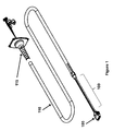
- Figure 1 depicts an exemplary embodiment of a cable assembly 100 that connects a probe tip 105 to an instrument interface 115 through instrument cable 110.
- cable assembly 100 only needs to be a few inches long to relieve mechanical stresses from the cable. This can be useful, for example, when the instrument cable 110 needs to have a strong outer shield to protect it from electrical interference or mechanical damage. Cable assembly 100 may be longer in other embodiments, however. For example, when a strong outer shield is not as important.
- cable assembly 100 may connect the probe tip 105 directly to the instrument interface 115, without instrument cable 110.
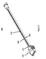
- cable assembly 100 may comprise one or more signal cables 205 and a spine 210, as shown in Figure 2 .
- Each of signal cables 205 carries information between the probe tip 105 and a test or measurement instrument.
- signal cables 205 may be coaxial cables, however any suitable type of cables known in the art, such as triaxial or optical cables may also be used.
- Spine 210 counteracts the signal cables' resistance to bending and twisting, which allows the cable assembly 100 to remain in position without adding mechanical stress to the DUT-probe interface.
- Spine 210 is normally selected from an appropriate gauge and material to counteract the properties of signal cables 205.
- the pliable spine 210 may consist of a copper 0.81 mm diameter (20 AWG (American Wire Gauge)) dead-soft wire.
- AWG American Wire Gauge
- users may prefer a stiffer spine. This could reassure the user that the cable assembly will eliminate cable stresses.
- Other users may prefer a softer spine for applications where flexibility is more important and cable stresses are not as much of a concern.
- spine 210 may be softer or stiffer in order to provide the user with a desired cable feel.
- An anchor 212 at probe tip 105 may be used to secure spine 210 and prevent it from moving with respect to the probe tip 105.
- the anchor may be a U-shaped bend in spine 210 that loops around a section of probe tip 105.
- the anchor may comprise an L-shaped section of spine that is received by a hole or slot in probe tip 105. Any other suitable anchor mechanisms known in the art to secure spine 210 to probe tip 105 may also be used.
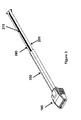
- the cable assembly 100 may be enclosed in a flexible housing 300.
- Housing 300 secures spine 210 with respect to signal cables 205.
- spine 210 is electrically conductive
- housing 300 may also act as an insulator.
- housing 300 may be heat shrink tubing, however any other suitable material or securing system may also be used.
- housing 300 may comprise tape, fitted tubing, one or more ties, clamps, etc.
- one or more additional anchors or bends in spine 210 may be added to prevent signal cables 205 from moving with respect to spine 210.
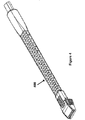
- Figure 4 shows one embodiment of a flexible boot 400 that covers housing 300 and cable assembly 100. Sections of boot 400 are cut out in order to allow the boot to flex, while preventing the boot from flexing too far. This protects the signal cables 205 from damage that could occur if they were bent too sharply.
- the diameter of boot 400 reduces towards the probe tip 105, which allows the cable assembly 100 to have the greatest range of motion at the probe tip 105.
- spine 210 is depicted as a single wire running down the center of cable assembly 100. In other embodiments, however, spine 210 may comprise any appropriate shape such as flat, concave, or more complex shapes. Spine 210 may also be located inside of boot 400. An anchor consisting of a U-shaped or L-shaped portion of spine 210 can be received by the boot. For example, spine 210 may be inserted into a hole or channel inside boot 400. In other embodiments, spine 210 may be molded directly into boot 400. These embodiments might eliminate the need for housing 300, which could reduce cost and make cable assembly 100 more flexible. These embodiments might also allow spine 210 and boot 400 to be added to existing probe cables, improving those cables for minimal cost.
- spine 210 may also be used with any number of signal cables.
- spine 210 may be used with a cable assembly that has a single signal cable 205.
- spine 210 may also comprise multiple spines. For example, when there are several signal cables, it may be desirable to use two or more spines to counteract the signal cables' resistance to bending or twisting.
- Examples provide a cable assembly for an electrical test probe, comprising one or more signal cables (205), and a pliable spine (210) proximate to the one or more signal cables (205).
- Some examples further comprise an anchor (212) that connects the pliable spine (210) to a probe tip (105).
- the anchor (212) is a first anchor and the pliable spine (210) comprises one or more second anchors that limit the motion of the one or more signal cables (205) with respect to the pliable spine (210).
- the anchor (212) consists of a U-shaped portion of the pliable spine (210) that is received by the probe tip (105).
- the anchor (212) consists of an L-shaped portion of the pliable spine (210) that is received by the probe tip (105).
- a first end of the cable assembly is connected to the probe tip (105), and a second end of the cable assembly is connected to an instrument cable (110).
- Some examples further comprise a flexible housing (300) that secures the pliable spine (210) to the one or more signal cables (205).
- Some examples further comprise a flexible boot (400) that surrounds the one or more signal cables (205), the pliable spine (210), and the flexible housing (300).
- the outer diameter of the flexible boot (400) is smallest at the probe tip (105), and increases in diameter further away from the probe tip (105).
- the pliable spine (210) is located inside the flexible boot (400).
- the anchor (212) consists of a U-shaped portion of the pliable spine (210) that is received by the boot (400).
- the anchor (212) consists of an L-shaped portion of the pliable spine (210) that is received by the boot (400).
- the pliable spine (210) is inserted into a channel in the flexible boot (400).
- the pliable spine (210) is molded into the flexible boot (400), and optionally the pliable spine is a pliable wire.
- Examples provide a method of assembling a cable assembly for an electrical test probe, comprising placing a pliable spine (210) proximate to one or more signal cables (205), and securing the pliable spine (210) to the one or more signal cables (205), optionally wherein the pliable spine is a pliable wire.
Landscapes
- Physics & Mathematics (AREA)
- General Physics & Mathematics (AREA)
- Engineering & Computer Science (AREA)
- Computer Hardware Design (AREA)
- Microelectronics & Electronic Packaging (AREA)
- General Engineering & Computer Science (AREA)
- Measuring Leads Or Probes (AREA)
- Details Of Connecting Devices For Male And Female Coupling (AREA)
- Ultra Sonic Daignosis Equipment (AREA)
Abstract
Description
- The present invention relates to an improved cable assembly for electrical test and measurement instrument probes.
- Electrical test and measurement instruments such as oscilloscopes use a probe to interface with the device under test ("DUT"). The probe connects the DUT to the instrument, through a cable. The DUT often cannot be directly lined up with the instrument, causing the cable to bend or twist. The cable typically resists being bent or twisted, which introduces mechanical stresses to the interface between the probe and the DUT. These stresses can compromise the probe's connection to the DUT or even damage the interface.
- Previous attempts to eliminate these stresses have involved securing the probe tip to the DUT, or securing the cables so that they cannot impart any mechanical stress to the DUT. For example, securing the probe tip to the DUT using tape or glue, or anchoring the cable to a stationary point near the DUT. These solutions, however, require extra work when connecting the probe to the DUT. They also prevent the probe from being easily disconnected when another device needs to be tested. Some solutions may even damage the interface between the probe and DUT when the probe is disconnected.
- Attempts have also been made to manufacture a cable with an outer jacket material that makes the cable more formable. This reduces some, but not all of the cable's resistance to twisting. And because the formable outer jacket does not protect the cable as well against damage, the performance of these cables tends to deteriorate over time.
- Thus, there is a need for a cable assembly that will eliminate the mechanical stresses to the DUT interface that are caused by the cable's resistance to bending and twisting, while protecting the cable from damage.
- Embodiments of the present invention provide an improved probe cable assembly for electrical test and measurement instruments that reduces mechanical stresses normally caused by the cable's resistance to bending and twisting. A pliable spine holds the cable assembly in position after it has been bent or twisted, preventing mechanical stresses to the probe's interface with the device under test. A flexible boot surrounds the cable assembly, allowing it to bend and twist within a range of motion that will not damage the assembly.
- The objects, advantages, and other novel features of the present invention are apparent from the following detailed description when read in conjunction with the appended claims and attached drawings.
-
-
FIG. 1 depicts an exemplary embodiment of a probe with cable assembly, instrument cable, and instrument interface -
FIG. 2 depicts an exemplary embodiment of a probe cable assembly -
FIG. 3 depicts an exemplary embodiment of a probe cable assembly with a flexible jacket -
FIG. 4 depicts an exemplary embodiment of a flexible boot - In order to measure signals in a device under test ("DUT"), test and measurement instruments such as oscilloscopes use a probe to connect to the device. The probe connects to the instrument via one or more signal cables. Usually, the DUT and instrument cannot be lined up perfectly, and the cables must be bent or twisted into position.
- Unfortunately, the cables used in electrical test and measurement instruments typically resist bending and twisting. For example, coaxial cable (also referred to as "coax") is commonly used because it shields the test and measurement signals from electrical interference and resists being crushed. Once it is bent or twisted, however, most coax will attempt to return to its original position. This imparts mechanical stresses to the interface between the probe and DUT.
- These mechanical stresses can compromise the integrity of the connection, or worse, damage the interface. Both can occur easily when the probe is attached to a small or fragile DUT interface. For example, some interfaces may consist of one or more delicate 0.1 mm (0.004 inch) diameter wires that connect the probe to the device.
- Accordingly, embodiments of the present invention provide an improved test probe cable assembly that retains its position after being bent or twisted thus imparting fewer mechanical stresses to the probe-DUT interface.
-
Figure 1 depicts an exemplary embodiment of acable assembly 100 that connects aprobe tip 105 to aninstrument interface 115 throughinstrument cable 110. In most embodiments,cable assembly 100 only needs to be a few inches long to relieve mechanical stresses from the cable. This can be useful, for example, when theinstrument cable 110 needs to have a strong outer shield to protect it from electrical interference or mechanical damage.Cable assembly 100 may be longer in other embodiments, however. For example, when a strong outer shield is not as important. In some embodiments,cable assembly 100 may connect theprobe tip 105 directly to theinstrument interface 115, withoutinstrument cable 110. - In one embodiment,
cable assembly 100 may comprise one ormore signal cables 205 and aspine 210, as shown inFigure 2 . Each ofsignal cables 205 carries information between theprobe tip 105 and a test or measurement instrument. In one embodiment,signal cables 205 may be coaxial cables, however any suitable type of cables known in the art, such as triaxial or optical cables may also be used. -
Spine 210 counteracts the signal cables' resistance to bending and twisting, which allows thecable assembly 100 to remain in position without adding mechanical stress to the DUT-probe interface.Spine 210 is normally selected from an appropriate gauge and material to counteract the properties ofsignal cables 205. For example, in one embodiment thepliable spine 210 may consist of a copper 0.81 mm diameter (20 AWG (American Wire Gauge)) dead-soft wire. In some cases, however, users may prefer a stiffer spine. This could reassure the user that the cable assembly will eliminate cable stresses. Other users may prefer a softer spine for applications where flexibility is more important and cable stresses are not as much of a concern. For example, when connecting the probe to a more robust DUT interface. Thus, in someembodiments spine 210 may be softer or stiffer in order to provide the user with a desired cable feel. - An
anchor 212 atprobe tip 105 may be used to securespine 210 and prevent it from moving with respect to theprobe tip 105. In one embodiment, the anchor may be a U-shaped bend inspine 210 that loops around a section ofprobe tip 105. In other embodiments, the anchor may comprise an L-shaped section of spine that is received by a hole or slot inprobe tip 105. Any other suitable anchor mechanisms known in the art to securespine 210 toprobe tip 105 may also be used. - As shown in
Figure 3 , thecable assembly 100 may be enclosed in aflexible housing 300.Housing 300 securesspine 210 with respect tosignal cables 205. For embodiments in whichspine 210 is electrically conductive,housing 300 may also act as an insulator. In one embodiment,housing 300 may be heat shrink tubing, however any other suitable material or securing system may also be used. For example, in some embodiments housing 300 may comprise tape, fitted tubing, one or more ties, clamps, etc. In some embodiments, one or more additional anchors or bends inspine 210 may be added to preventsignal cables 205 from moving with respect tospine 210. -
Figure 4 shows one embodiment of aflexible boot 400 that covershousing 300 andcable assembly 100. Sections ofboot 400 are cut out in order to allow the boot to flex, while preventing the boot from flexing too far. This protects thesignal cables 205 from damage that could occur if they were bent too sharply. The diameter ofboot 400 reduces towards theprobe tip 105, which allows thecable assembly 100 to have the greatest range of motion at theprobe tip 105. - In
Figure 2 ,spine 210 is depicted as a single wire running down the center ofcable assembly 100. In other embodiments, however,spine 210 may comprise any appropriate shape such as flat, concave, or more complex shapes.Spine 210 may also be located inside ofboot 400. An anchor consisting of a U-shaped or L-shaped portion ofspine 210 can be received by the boot. For example,spine 210 may be inserted into a hole or channel insideboot 400. In other embodiments,spine 210 may be molded directly intoboot 400. These embodiments might eliminate the need forhousing 300, which could reduce cost and makecable assembly 100 more flexible. These embodiments might also allowspine 210 and boot 400 to be added to existing probe cables, improving those cables for minimal cost. - Although
Figures 1-4 depict an embodiment in which twosignal cables 205 are used,spine 210 may also be used with any number of signal cables. For example,spine 210 may be used with a cable assembly that has asingle signal cable 205. In some embodiments,spine 210 may also comprise multiple spines. For example, when there are several signal cables, it may be desirable to use two or more spines to counteract the signal cables' resistance to bending or twisting. - Examples provide a cable assembly for an electrical test probe, comprising one or more signal cables (205), and a pliable spine (210) proximate to the one or more signal cables (205).
- Some examples further comprise an anchor (212) that connects the pliable spine (210) to a probe tip (105).
- In some examples, the anchor (212) is a first anchor and the pliable spine (210) comprises one or more second anchors that limit the motion of the one or more signal cables (205) with respect to the pliable spine (210).
- In some examples, the anchor (212) consists of a U-shaped portion of the pliable spine (210) that is received by the probe tip (105).
- In some examples, the anchor (212) consists of an L-shaped portion of the pliable spine (210) that is received by the probe tip (105).
- In some examples, a first end of the cable assembly is connected to the probe tip (105), and a second end of the cable assembly is connected to an instrument cable (110).
- Some examples further comprise a flexible housing (300) that secures the pliable spine (210) to the one or more signal cables (205).
- Some examples further comprise a flexible boot (400) that surrounds the one or more signal cables (205), the pliable spine (210), and the flexible housing (300).
- In some examples, the outer diameter of the flexible boot (400) is smallest at the probe tip (105), and increases in diameter further away from the probe tip (105).
- In some examples, the pliable spine (210) is located inside the flexible boot (400).
- In some examples, the anchor (212) consists of a U-shaped portion of the pliable spine (210) that is received by the boot (400).
- In some examples, the anchor (212) consists of an L-shaped portion of the pliable spine (210) that is received by the boot (400).
- In some examples, the pliable spine (210) is inserted into a channel in the flexible boot (400).
- In some examples, the pliable spine (210) is molded into the flexible boot (400), and optionally the pliable spine is a pliable wire.
- Examples provide a method of assembling a cable assembly for an electrical test probe, comprising placing a pliable spine (210) proximate to one or more signal cables (205), and securing the pliable spine (210) to the one or more signal cables (205), optionally wherein the pliable spine is a pliable wire.
- Although specific embodiments of the invention have been described for purposes of illustration, it will be apparent to those skilled in the art that various modifications may be made without departing from the scope of the invention. Accordingly, the invention should not be limited except as by the appended claims.
Claims (15)
- A cable assembly for an electrical test probe, comprising:one or more signal cables (205); anda pliable spine (210) proximate to the one or more signal cables (205).
- The cable assembly of claim 1, further comprising an anchor (212) that connects the pliable spine (210) to a probe tip (105).
- The cable assembly of claim 2, wherein the anchor (212) is a first anchor and the pliable spine (210) comprises one or more second anchors that limit the motion of the one or more signal cables (205) with respect to the pliable spine (210).
- The cable assembly of claim 2 or 3, wherein the anchor (212) consists of a U-shaped portion of the pliable spine (210) that is received by the probe tip (105).
- The cable assembly of claim 2 or 3, wherein the anchor (212) consists of an L-shaped portion of the pliable spine (210) that is received by the probe tip (105).
- The cable assembly of any previous claim, wherein a first end of the cable assembly is connected to the probe tip (105), and a second end of the cable assembly is connected to an instrument cable (110).
- The cable assembly of any previous claim, further comprising a flexible housing (300) that secures the pliable spine (210) to the one or more signal cables (205).
- The cable assembly of claim 7, further comprising a flexible boot (400) that surrounds the one or more signal cables (205), the pliable spine (210), and the flexible housing (300).
- The cable assembly of claim 8, wherein the outer diameter of the flexible boot (400) is smallest at the probe tip (105), and increases in diameter further away from the probe tip (105).
- The cable assembly of claim 8, wherein the pliable spine (210) is located inside the flexible boot (400).
- The cable assembly of claim 10, wherein the anchor (212) consists of a U-shaped portion of the pliable spine (210) that is received by the boot (400).
- The cable assembly of claim 10, wherein the anchor (212) consists of an L-shaped portion of the pliable spine (210) that is received by the boot (400).
- The cable assembly of claim 10, wherein the pliable spine (210) is inserted into a channel in the flexible boot (400).
- The cable assembly of claim 10, wherein the pliable spine (210) is molded into the flexible boot (400).
- A method of assembling a cable assembly for an electrical test probe, comprising:placing a pliable spine (210) proximate to one or more signal cables (205); andsecuring the pliable spine (210) to the one or more signal cables (205).
Applications Claiming Priority (1)
| Application Number | Priority Date | Filing Date | Title |
|---|---|---|---|
| US14/823,903 US10228390B2 (en) | 2015-08-11 | 2015-08-11 | Cable assembly with spine for instrument probe |
Publications (2)
| Publication Number | Publication Date |
|---|---|
| EP3130928A1 true EP3130928A1 (en) | 2017-02-15 |
| EP3130928B1 EP3130928B1 (en) | 2021-04-14 |
Family
ID=56682005
Family Applications (1)
| Application Number | Title | Priority Date | Filing Date |
|---|---|---|---|
| EP16183615.0A Active EP3130928B1 (en) | 2015-08-11 | 2016-08-10 | Cable assembly with spine for instrument probe |
Country Status (4)
| Country | Link |
|---|---|
| US (1) | US10228390B2 (en) |
| EP (1) | EP3130928B1 (en) |
| JP (1) | JP6955819B2 (en) |
| CN (1) | CN106450994B (en) |
Cited By (3)
| Publication number | Priority date | Publication date | Assignee | Title |
|---|---|---|---|---|
| US10886588B2 (en) | 2018-09-26 | 2021-01-05 | Keysight Technologies, Inc. | High dynamic range probe using pole-zero cancellation |
| US12498398B2 (en) | 2023-02-23 | 2025-12-16 | Snap-On Incorporated | Electrical testing device with probe having an adjustable angle |
| US12504442B2 (en) | 2023-02-23 | 2025-12-23 | Snap-On Incorporated | Electrical testing device with probe having portions with different cross-sectional areas |
Families Citing this family (4)
| Publication number | Priority date | Publication date | Assignee | Title |
|---|---|---|---|---|
| JP2018066567A (en) * | 2016-10-17 | 2018-04-26 | 横河電機株式会社 | Probe device |
| US11300480B2 (en) * | 2020-02-28 | 2022-04-12 | Baker Hughes Oilfield Operations Llc | Articulated non-destructive testing device having a plurality of actuation systems and a method of articulating the device |
| JP2023527519A (en) * | 2020-05-20 | 2023-06-29 | コムスコープ テクノロジーズ リミティド ライアビリティ カンパニー | active optical cable assembly |
| CN116075685A (en) * | 2020-09-01 | 2023-05-05 | 大塚电子株式会社 | Optical measurement system, optical measurement method, and measurement program |
Citations (3)
| Publication number | Priority date | Publication date | Assignee | Title |
|---|---|---|---|---|
| US20040182170A1 (en) * | 2003-03-17 | 2004-09-23 | Harju Rey P. | Test lead connector with strain relief |
| DE202010009369U1 (en) * | 2010-06-22 | 2010-08-26 | Brymen Technology Corporation, Chung-Ho City | Multimeter with a flexible current sensor |
| US20120153980A1 (en) * | 2010-12-21 | 2012-06-21 | Hon Hai Precision Industry Co., Ltd. | Probe assembly |
Family Cites Families (20)
| Publication number | Priority date | Publication date | Assignee | Title |
|---|---|---|---|---|
| JPH04100461U (en) * | 1991-01-24 | 1992-08-31 | ||
| US6169834B1 (en) * | 1998-05-13 | 2001-01-02 | Alcatel | Slotted composite cable having a cable housing with a tubular opening for copper pairs and a slot for an optical fiber |
| US7113679B2 (en) * | 2000-05-26 | 2006-09-26 | Corning Cable Systems, Llc | Fiber optic drop cables and preconnectorized assemblies having toning portions |
| JP3867273B2 (en) * | 2002-12-04 | 2007-01-10 | 株式会社オーシーシー | Optical fiber retainer |
| JP2004274951A (en) * | 2003-03-11 | 2004-09-30 | Auto Network Gijutsu Kenkyusho:Kk | Wiring harness wiring structure |
| US6933713B2 (en) * | 2004-01-26 | 2005-08-23 | Agilent Technologies, Inc. | High bandwidth oscilloscope probe with replaceable cable |
| CN100576642C (en) * | 2004-04-02 | 2009-12-30 | 迈克尔·B·霍珀 | Quick release connector assembly |
| US9404940B1 (en) * | 2006-01-06 | 2016-08-02 | Teledyne Lecroy, Inc. | Compensating probing tip optimized adapters for use with specific electrical test probes |
| US7294995B1 (en) * | 2006-05-08 | 2007-11-13 | Tektronix, Inc. | Current probing system |
| US7270485B1 (en) * | 2006-06-23 | 2007-09-18 | Carlyle, Inc. | Device for furcating fiber optic cables |
| US7460753B2 (en) * | 2006-07-06 | 2008-12-02 | Anthony Stephen Kewitsch | Shape-retaining fiber optic cables having limited bend radius |
| US20080250632A1 (en) * | 2007-02-12 | 2008-10-16 | Dayton Douglas C | System and method of a conformable cable |
| US7756374B2 (en) * | 2007-04-05 | 2010-07-13 | Corning Cable Systems Llc | Cable assembly with access point |
| US20090204118A1 (en) * | 2008-02-13 | 2009-08-13 | William Ralph Pratt | Surgical cable with malleable leader segment |
| US8450610B2 (en) * | 2008-07-30 | 2013-05-28 | Iconn Systems, Llc | Cable connector assembly |
| US8184939B2 (en) * | 2008-08-01 | 2012-05-22 | 3M Innovative Properties Company | Optical fiber cable inlet device with integral optical device |
| US8308505B2 (en) * | 2009-12-09 | 2012-11-13 | Scott Hatton | Guarded coaxial cable assembly |
| CN201853919U (en) * | 2010-10-15 | 2011-06-01 | 江苏帝一集团有限公司 | Network terminal junction box |
| US9007083B2 (en) * | 2011-08-03 | 2015-04-14 | Tektronix, Inc. | Self-retaining via probe |
| US9741473B2 (en) * | 2014-12-10 | 2017-08-22 | Bby Solutions, Inc. | Cable with an integrated coiling and reinforcing wrapper |
-
2015
- 2015-08-11 US US14/823,903 patent/US10228390B2/en active Active
-
2016
- 2016-08-09 JP JP2016156606A patent/JP6955819B2/en active Active
- 2016-08-10 EP EP16183615.0A patent/EP3130928B1/en active Active
- 2016-08-11 CN CN201610840078.3A patent/CN106450994B/en active Active
Patent Citations (3)
| Publication number | Priority date | Publication date | Assignee | Title |
|---|---|---|---|---|
| US20040182170A1 (en) * | 2003-03-17 | 2004-09-23 | Harju Rey P. | Test lead connector with strain relief |
| DE202010009369U1 (en) * | 2010-06-22 | 2010-08-26 | Brymen Technology Corporation, Chung-Ho City | Multimeter with a flexible current sensor |
| US20120153980A1 (en) * | 2010-12-21 | 2012-06-21 | Hon Hai Precision Industry Co., Ltd. | Probe assembly |
Cited By (3)
| Publication number | Priority date | Publication date | Assignee | Title |
|---|---|---|---|---|
| US10886588B2 (en) | 2018-09-26 | 2021-01-05 | Keysight Technologies, Inc. | High dynamic range probe using pole-zero cancellation |
| US12498398B2 (en) | 2023-02-23 | 2025-12-16 | Snap-On Incorporated | Electrical testing device with probe having an adjustable angle |
| US12504442B2 (en) | 2023-02-23 | 2025-12-23 | Snap-On Incorporated | Electrical testing device with probe having portions with different cross-sectional areas |
Also Published As
| Publication number | Publication date |
|---|---|
| JP6955819B2 (en) | 2021-10-27 |
| JP2017037072A (en) | 2017-02-16 |
| CN106450994A (en) | 2017-02-22 |
| CN106450994B (en) | 2022-11-01 |
| US20170045550A1 (en) | 2017-02-16 |
| EP3130928B1 (en) | 2021-04-14 |
| US10228390B2 (en) | 2019-03-12 |
Similar Documents
| Publication | Publication Date | Title |
|---|---|---|
| EP3130928B1 (en) | Cable assembly with spine for instrument probe | |
| JP6033333B2 (en) | Electrical connection part for video endoscope, video endoscope, and method for making electrical connection of video endoscope | |
| US20130279864A1 (en) | Downhole cables with both fiber and copper elements | |
| KR20030094314A (en) | Flexible interconnect cable with ribbonized ends | |
| US20170303388A1 (en) | Flat cable strain relief with controlled mechanical resistance | |
| JPS63108615A (en) | Bending radius transmission cable with controlled and limited torsion variation | |
| EP1096509B1 (en) | Multiconductor cable | |
| CN107919539A (en) | Conducting channel | |
| CN105976930A (en) | Anti-counterfeit cable | |
| CN103827985A (en) | Coax ribbonizing header | |
| TW469665B (en) | Method for making antenna of coaxial cable and the antenna so made | |
| JP5459049B2 (en) | Signal transmission cable connector, signal transmission cable with connector using the same, and electrical connection portion of signal transmission cable | |
| CN103808982A (en) | Voltage probe | |
| EP2921864A1 (en) | Current Sensor | |
| JP2003014998A (en) | Optical fiber | |
| US20030236020A1 (en) | Field installable, field adjustable angled boot for multi-conductor cables and process for installing the same | |
| CN210040648U (en) | Connector for calibrating digital thermometer | |
| KR20150001973U (en) | Multi-core cable with connectors | |
| CN106205808A (en) | A kind of super flexible robot's cable | |
| US12571816B2 (en) | High-impedance differential flexible probe tip | |
| WO2017210544A1 (en) | Downhole logging cables with central conductors | |
| CN222279951U (en) | Phi 0.4 fine armoured thermocouple | |
| US20130038344A1 (en) | Probe assembly | |
| US20250147238A1 (en) | Fiber splice protector configured to permit routing of a fiber splice connection along a curved path without degrading optical and mechanical performance of the fiber splice connection | |
| JP2004342578A (en) | Self inductance reducing signal cable and method for reducing self inductance of signal cable |
Legal Events
| Date | Code | Title | Description |
|---|---|---|---|
| PUAI | Public reference made under article 153(3) epc to a published international application that has entered the european phase |
Free format text: ORIGINAL CODE: 0009012 |
|
| STAA | Information on the status of an ep patent application or granted ep patent |
Free format text: STATUS: THE APPLICATION HAS BEEN PUBLISHED |
|
| AK | Designated contracting states |
Kind code of ref document: A1 Designated state(s): AL AT BE BG CH CY CZ DE DK EE ES FI FR GB GR HR HU IE IS IT LI LT LU LV MC MK MT NL NO PL PT RO RS SE SI SK SM TR |
|
| AX | Request for extension of the european patent |
Extension state: BA ME |
|
| RIN1 | Information on inventor provided before grant (corrected) |
Inventor name: ENGGUIST, DAVID Inventor name: MCGRATH, JAMES |
|
| STAA | Information on the status of an ep patent application or granted ep patent |
Free format text: STATUS: REQUEST FOR EXAMINATION WAS MADE |
|
| 17P | Request for examination filed |
Effective date: 20170815 |
|
| RBV | Designated contracting states (corrected) |
Designated state(s): AL AT BE BG CH CY CZ DE DK EE ES FI FR GB GR HR HU IE IS IT LI LT LU LV MC MK MT NL NO PL PT RO RS SE SI SK SM TR |
|
| STAA | Information on the status of an ep patent application or granted ep patent |
Free format text: STATUS: EXAMINATION IS IN PROGRESS |
|
| 17Q | First examination report despatched |
Effective date: 20171215 |
|
| GRAP | Despatch of communication of intention to grant a patent |
Free format text: ORIGINAL CODE: EPIDOSNIGR1 |
|
| STAA | Information on the status of an ep patent application or granted ep patent |
Free format text: STATUS: GRANT OF PATENT IS INTENDED |
|
| INTG | Intention to grant announced |
Effective date: 20201028 |
|
| GRAS | Grant fee paid |
Free format text: ORIGINAL CODE: EPIDOSNIGR3 |
|
| GRAA | (expected) grant |
Free format text: ORIGINAL CODE: 0009210 |
|
| STAA | Information on the status of an ep patent application or granted ep patent |
Free format text: STATUS: THE PATENT HAS BEEN GRANTED |
|
| AK | Designated contracting states |
Kind code of ref document: B1 Designated state(s): AL AT BE BG CH CY CZ DE DK EE ES FI FR GB GR HR HU IE IS IT LI LT LU LV MC MK MT NL NO PL PT RO RS SE SI SK SM TR |
|
| REG | Reference to a national code |
Ref country code: GB Ref legal event code: FG4D |
|
| REG | Reference to a national code |
Ref country code: CH Ref legal event code: EP |
|
| REG | Reference to a national code |
Ref country code: DE Ref legal event code: R096 Ref document number: 602016055986 Country of ref document: DE |
|
| REG | Reference to a national code |
Ref country code: IE Ref legal event code: FG4D |
|
| REG | Reference to a national code |
Ref country code: AT Ref legal event code: REF Ref document number: 1382888 Country of ref document: AT Kind code of ref document: T Effective date: 20210515 |
|
| REG | Reference to a national code |
Ref country code: CH Ref legal event code: PK Free format text: BERICHTIGUNGEN |
|
| RIN2 | Information on inventor provided after grant (corrected) |
Inventor name: ENGQUIST, DAVID Inventor name: MCGRATH, JAMES |
|
| REG | Reference to a national code |
Ref country code: LT Ref legal event code: MG9D |
|
| REG | Reference to a national code |
Ref country code: AT Ref legal event code: MK05 Ref document number: 1382888 Country of ref document: AT Kind code of ref document: T Effective date: 20210414 |
|
| REG | Reference to a national code |
Ref country code: NL Ref legal event code: MP Effective date: 20210414 |
|
| PG25 | Lapsed in a contracting state [announced via postgrant information from national office to epo] |
Ref country code: FI Free format text: LAPSE BECAUSE OF FAILURE TO SUBMIT A TRANSLATION OF THE DESCRIPTION OR TO PAY THE FEE WITHIN THE PRESCRIBED TIME-LIMIT Effective date: 20210414 Ref country code: NL Free format text: LAPSE BECAUSE OF FAILURE TO SUBMIT A TRANSLATION OF THE DESCRIPTION OR TO PAY THE FEE WITHIN THE PRESCRIBED TIME-LIMIT Effective date: 20210414 Ref country code: LT Free format text: LAPSE BECAUSE OF FAILURE TO SUBMIT A TRANSLATION OF THE DESCRIPTION OR TO PAY THE FEE WITHIN THE PRESCRIBED TIME-LIMIT Effective date: 20210414 Ref country code: HR Free format text: LAPSE BECAUSE OF FAILURE TO SUBMIT A TRANSLATION OF THE DESCRIPTION OR TO PAY THE FEE WITHIN THE PRESCRIBED TIME-LIMIT Effective date: 20210414 Ref country code: AT Free format text: LAPSE BECAUSE OF FAILURE TO SUBMIT A TRANSLATION OF THE DESCRIPTION OR TO PAY THE FEE WITHIN THE PRESCRIBED TIME-LIMIT Effective date: 20210414 Ref country code: BG Free format text: LAPSE BECAUSE OF FAILURE TO SUBMIT A TRANSLATION OF THE DESCRIPTION OR TO PAY THE FEE WITHIN THE PRESCRIBED TIME-LIMIT Effective date: 20210714 |
|
| PG25 | Lapsed in a contracting state [announced via postgrant information from national office to epo] |
Ref country code: GR Free format text: LAPSE BECAUSE OF FAILURE TO SUBMIT A TRANSLATION OF THE DESCRIPTION OR TO PAY THE FEE WITHIN THE PRESCRIBED TIME-LIMIT Effective date: 20210715 Ref country code: IS Free format text: LAPSE BECAUSE OF FAILURE TO SUBMIT A TRANSLATION OF THE DESCRIPTION OR TO PAY THE FEE WITHIN THE PRESCRIBED TIME-LIMIT Effective date: 20210814 Ref country code: LV Free format text: LAPSE BECAUSE OF FAILURE TO SUBMIT A TRANSLATION OF THE DESCRIPTION OR TO PAY THE FEE WITHIN THE PRESCRIBED TIME-LIMIT Effective date: 20210414 Ref country code: PT Free format text: LAPSE BECAUSE OF FAILURE TO SUBMIT A TRANSLATION OF THE DESCRIPTION OR TO PAY THE FEE WITHIN THE PRESCRIBED TIME-LIMIT Effective date: 20210816 Ref country code: NO Free format text: LAPSE BECAUSE OF FAILURE TO SUBMIT A TRANSLATION OF THE DESCRIPTION OR TO PAY THE FEE WITHIN THE PRESCRIBED TIME-LIMIT Effective date: 20210714 Ref country code: PL Free format text: LAPSE BECAUSE OF FAILURE TO SUBMIT A TRANSLATION OF THE DESCRIPTION OR TO PAY THE FEE WITHIN THE PRESCRIBED TIME-LIMIT Effective date: 20210414 Ref country code: ES Free format text: LAPSE BECAUSE OF FAILURE TO SUBMIT A TRANSLATION OF THE DESCRIPTION OR TO PAY THE FEE WITHIN THE PRESCRIBED TIME-LIMIT Effective date: 20210414 Ref country code: SE Free format text: LAPSE BECAUSE OF FAILURE TO SUBMIT A TRANSLATION OF THE DESCRIPTION OR TO PAY THE FEE WITHIN THE PRESCRIBED TIME-LIMIT Effective date: 20210414 Ref country code: RS Free format text: LAPSE BECAUSE OF FAILURE TO SUBMIT A TRANSLATION OF THE DESCRIPTION OR TO PAY THE FEE WITHIN THE PRESCRIBED TIME-LIMIT Effective date: 20210414 |
|
| REG | Reference to a national code |
Ref country code: DE Ref legal event code: R097 Ref document number: 602016055986 Country of ref document: DE |
|
| PG25 | Lapsed in a contracting state [announced via postgrant information from national office to epo] |
Ref country code: SM Free format text: LAPSE BECAUSE OF FAILURE TO SUBMIT A TRANSLATION OF THE DESCRIPTION OR TO PAY THE FEE WITHIN THE PRESCRIBED TIME-LIMIT Effective date: 20210414 Ref country code: SK Free format text: LAPSE BECAUSE OF FAILURE TO SUBMIT A TRANSLATION OF THE DESCRIPTION OR TO PAY THE FEE WITHIN THE PRESCRIBED TIME-LIMIT Effective date: 20210414 Ref country code: CZ Free format text: LAPSE BECAUSE OF FAILURE TO SUBMIT A TRANSLATION OF THE DESCRIPTION OR TO PAY THE FEE WITHIN THE PRESCRIBED TIME-LIMIT Effective date: 20210414 Ref country code: DK Free format text: LAPSE BECAUSE OF FAILURE TO SUBMIT A TRANSLATION OF THE DESCRIPTION OR TO PAY THE FEE WITHIN THE PRESCRIBED TIME-LIMIT Effective date: 20210414 Ref country code: EE Free format text: LAPSE BECAUSE OF FAILURE TO SUBMIT A TRANSLATION OF THE DESCRIPTION OR TO PAY THE FEE WITHIN THE PRESCRIBED TIME-LIMIT Effective date: 20210414 Ref country code: RO Free format text: LAPSE BECAUSE OF FAILURE TO SUBMIT A TRANSLATION OF THE DESCRIPTION OR TO PAY THE FEE WITHIN THE PRESCRIBED TIME-LIMIT Effective date: 20210414 |
|
| PLBE | No opposition filed within time limit |
Free format text: ORIGINAL CODE: 0009261 |
|
| STAA | Information on the status of an ep patent application or granted ep patent |
Free format text: STATUS: NO OPPOSITION FILED WITHIN TIME LIMIT |
|
| 26N | No opposition filed |
Effective date: 20220117 |
|
| REG | Reference to a national code |
Ref country code: CH Ref legal event code: PL |
|
| PG25 | Lapsed in a contracting state [announced via postgrant information from national office to epo] |
Ref country code: MC Free format text: LAPSE BECAUSE OF FAILURE TO SUBMIT A TRANSLATION OF THE DESCRIPTION OR TO PAY THE FEE WITHIN THE PRESCRIBED TIME-LIMIT Effective date: 20210414 |
|
| REG | Reference to a national code |
Ref country code: BE Ref legal event code: MM Effective date: 20210831 |
|
| GBPC | Gb: european patent ceased through non-payment of renewal fee |
Effective date: 20210810 |
|
| PG25 | Lapsed in a contracting state [announced via postgrant information from national office to epo] |
Ref country code: LI Free format text: LAPSE BECAUSE OF NON-PAYMENT OF DUE FEES Effective date: 20210831 Ref country code: CH Free format text: LAPSE BECAUSE OF NON-PAYMENT OF DUE FEES Effective date: 20210831 |
|
| PG25 | Lapsed in a contracting state [announced via postgrant information from national office to epo] |
Ref country code: IS Free format text: LAPSE BECAUSE OF FAILURE TO SUBMIT A TRANSLATION OF THE DESCRIPTION OR TO PAY THE FEE WITHIN THE PRESCRIBED TIME-LIMIT Effective date: 20210814 Ref country code: LU Free format text: LAPSE BECAUSE OF NON-PAYMENT OF DUE FEES Effective date: 20210810 Ref country code: AL Free format text: LAPSE BECAUSE OF FAILURE TO SUBMIT A TRANSLATION OF THE DESCRIPTION OR TO PAY THE FEE WITHIN THE PRESCRIBED TIME-LIMIT Effective date: 20210414 |
|
| PG25 | Lapsed in a contracting state [announced via postgrant information from national office to epo] |
Ref country code: IT Free format text: LAPSE BECAUSE OF FAILURE TO SUBMIT A TRANSLATION OF THE DESCRIPTION OR TO PAY THE FEE WITHIN THE PRESCRIBED TIME-LIMIT Effective date: 20210414 Ref country code: IE Free format text: LAPSE BECAUSE OF NON-PAYMENT OF DUE FEES Effective date: 20210810 Ref country code: GB Free format text: LAPSE BECAUSE OF NON-PAYMENT OF DUE FEES Effective date: 20210810 Ref country code: FR Free format text: LAPSE BECAUSE OF NON-PAYMENT OF DUE FEES Effective date: 20210831 Ref country code: BE Free format text: LAPSE BECAUSE OF NON-PAYMENT OF DUE FEES Effective date: 20210831 |
|
| PG25 | Lapsed in a contracting state [announced via postgrant information from national office to epo] |
Ref country code: HU Free format text: LAPSE BECAUSE OF FAILURE TO SUBMIT A TRANSLATION OF THE DESCRIPTION OR TO PAY THE FEE WITHIN THE PRESCRIBED TIME-LIMIT; INVALID AB INITIO Effective date: 20160810 |
|
| PG25 | Lapsed in a contracting state [announced via postgrant information from national office to epo] |
Ref country code: CY Free format text: LAPSE BECAUSE OF FAILURE TO SUBMIT A TRANSLATION OF THE DESCRIPTION OR TO PAY THE FEE WITHIN THE PRESCRIBED TIME-LIMIT Effective date: 20210414 |
|
| P01 | Opt-out of the competence of the unified patent court (upc) registered |
Effective date: 20230530 |
|
| PG25 | Lapsed in a contracting state [announced via postgrant information from national office to epo] |
Ref country code: MK Free format text: LAPSE BECAUSE OF FAILURE TO SUBMIT A TRANSLATION OF THE DESCRIPTION OR TO PAY THE FEE WITHIN THE PRESCRIBED TIME-LIMIT Effective date: 20210414 |
|
| PG25 | Lapsed in a contracting state [announced via postgrant information from national office to epo] |
Ref country code: TR Free format text: LAPSE BECAUSE OF FAILURE TO SUBMIT A TRANSLATION OF THE DESCRIPTION OR TO PAY THE FEE WITHIN THE PRESCRIBED TIME-LIMIT Effective date: 20210414 |
|
| PG25 | Lapsed in a contracting state [announced via postgrant information from national office to epo] |
Ref country code: MT Free format text: LAPSE BECAUSE OF FAILURE TO SUBMIT A TRANSLATION OF THE DESCRIPTION OR TO PAY THE FEE WITHIN THE PRESCRIBED TIME-LIMIT Effective date: 20210414 |
|
| PGFP | Annual fee paid to national office [announced via postgrant information from national office to epo] |
Ref country code: DE Payment date: 20250827 Year of fee payment: 10 |