EP3130886A1 - Tire mold engraving inspection method and device - Google Patents
Tire mold engraving inspection method and device Download PDFInfo
- Publication number
- EP3130886A1 EP3130886A1 EP15777214.6A EP15777214A EP3130886A1 EP 3130886 A1 EP3130886 A1 EP 3130886A1 EP 15777214 A EP15777214 A EP 15777214A EP 3130886 A1 EP3130886 A1 EP 3130886A1
- Authority
- EP
- European Patent Office
- Prior art keywords
- image
- data
- actual measurement
- side plate
- engraving
- Prior art date
- Legal status (The legal status is an assumption and is not a legal conclusion. Google has not performed a legal analysis and makes no representation as to the accuracy of the status listed.)
- Withdrawn
Links
Images



Classifications
-
- G—PHYSICS
- G01—MEASURING; TESTING
- G01B—MEASURING LENGTH, THICKNESS OR SIMILAR LINEAR DIMENSIONS; MEASURING ANGLES; MEASURING AREAS; MEASURING IRREGULARITIES OF SURFACES OR CONTOURS
- G01B11/00—Measuring arrangements characterised by the use of optical techniques
- G01B11/24—Measuring arrangements characterised by the use of optical techniques for measuring contours or curvatures
-
- G—PHYSICS
- G01—MEASURING; TESTING
- G01N—INVESTIGATING OR ANALYSING MATERIALS BY DETERMINING THEIR CHEMICAL OR PHYSICAL PROPERTIES
- G01N21/00—Investigating or analysing materials by the use of optical means, i.e. using sub-millimetre waves, infrared, visible or ultraviolet light
- G01N21/84—Systems specially adapted for particular applications
- G01N21/88—Investigating the presence of flaws or contamination
- G01N21/8851—Scan or image signal processing specially adapted therefor, e.g. for scan signal adjustment, for detecting different kinds of defects, for compensating for structures, markings, edges
-
- G—PHYSICS
- G01—MEASURING; TESTING
- G01N—INVESTIGATING OR ANALYSING MATERIALS BY DETERMINING THEIR CHEMICAL OR PHYSICAL PROPERTIES
- G01N21/00—Investigating or analysing materials by the use of optical means, i.e. using sub-millimetre waves, infrared, visible or ultraviolet light
- G01N21/84—Systems specially adapted for particular applications
- G01N21/88—Investigating the presence of flaws or contamination
- G01N21/95—Investigating the presence of flaws or contamination characterised by the material or shape of the object to be examined
-
- G—PHYSICS
- G01—MEASURING; TESTING
- G01N—INVESTIGATING OR ANALYSING MATERIALS BY DETERMINING THEIR CHEMICAL OR PHYSICAL PROPERTIES
- G01N21/00—Investigating or analysing materials by the use of optical means, i.e. using sub-millimetre waves, infrared, visible or ultraviolet light
- G01N21/84—Systems specially adapted for particular applications
- G01N21/88—Investigating the presence of flaws or contamination
- G01N21/95—Investigating the presence of flaws or contamination characterised by the material or shape of the object to be examined
- G01N21/9515—Objects of complex shape, e.g. examined with use of a surface follower device
-
- G—PHYSICS
- G01—MEASURING; TESTING
- G01N—INVESTIGATING OR ANALYSING MATERIALS BY DETERMINING THEIR CHEMICAL OR PHYSICAL PROPERTIES
- G01N21/00—Investigating or analysing materials by the use of optical means, i.e. using sub-millimetre waves, infrared, visible or ultraviolet light
- G01N21/84—Systems specially adapted for particular applications
- G01N21/88—Investigating the presence of flaws or contamination
- G01N21/95—Investigating the presence of flaws or contamination characterised by the material or shape of the object to be examined
- G01N21/956—Inspecting patterns on the surface of objects
- G01N21/95607—Inspecting patterns on the surface of objects using a comparative method
-
- G—PHYSICS
- G06—COMPUTING OR CALCULATING; COUNTING
- G06T—IMAGE DATA PROCESSING OR GENERATION, IN GENERAL
- G06T7/00—Image analysis
- G06T7/0002—Inspection of images, e.g. flaw detection
- G06T7/0004—Industrial image inspection
- G06T7/0008—Industrial image inspection checking presence/absence
-
- G—PHYSICS
- G06—COMPUTING OR CALCULATING; COUNTING
- G06T—IMAGE DATA PROCESSING OR GENERATION, IN GENERAL
- G06T7/00—Image analysis
- G06T7/0002—Inspection of images, e.g. flaw detection
- G06T7/0004—Industrial image inspection
- G06T7/001—Industrial image inspection using an image reference approach
-
- G—PHYSICS
- G06—COMPUTING OR CALCULATING; COUNTING
- G06T—IMAGE DATA PROCESSING OR GENERATION, IN GENERAL
- G06T7/00—Image analysis
- G06T7/30—Determination of transform parameters for the alignment of images, i.e. image registration
- G06T7/33—Determination of transform parameters for the alignment of images, i.e. image registration using feature-based methods
- G06T7/337—Determination of transform parameters for the alignment of images, i.e. image registration using feature-based methods involving reference images or patches
-
- G—PHYSICS
- G01—MEASURING; TESTING
- G01N—INVESTIGATING OR ANALYSING MATERIALS BY DETERMINING THEIR CHEMICAL OR PHYSICAL PROPERTIES
- G01N2201/00—Features of devices classified in G01N21/00
- G01N2201/12—Circuits of general importance; Signal processing
-
- G—PHYSICS
- G06—COMPUTING OR CALCULATING; COUNTING
- G06T—IMAGE DATA PROCESSING OR GENERATION, IN GENERAL
- G06T2207/00—Indexing scheme for image analysis or image enhancement
- G06T2207/10—Image acquisition modality
- G06T2207/10028—Range image; Depth image; 3D point clouds
-
- G—PHYSICS
- G06—COMPUTING OR CALCULATING; COUNTING
- G06T—IMAGE DATA PROCESSING OR GENERATION, IN GENERAL
- G06T2207/00—Indexing scheme for image analysis or image enhancement
- G06T2207/30—Subject of image; Context of image processing
- G06T2207/30108—Industrial image inspection
- G06T2207/30116—Casting
Definitions
- the present invention relates to a method and a device for inspecting engravings in a tire mold; and particularly relates to a method and a device for inspecting engravings in a tire mold capable of determining the suitability of engravings formed on a surface of an annular side plate, which is a component of the tire mold, in a reduced time and with high precision.
- a method of inspection determines the acceptability of a raised or depressed character string formed on a side surface of a manufactured pneumatic tire (see Patent Document 1).
- an image of the raised or depressed character string formed on the tire side surface is captured and an image pattern of the character string is generated. Thereafter, how much the generated image pattern is a match with a preset model pattern is calculated, and this result determines whether the character string is acceptable or not.
- a degree of match is obtained by comparing the three-dimensional data of the raised or depressed character string for inspection against a reference (model pattern) raised or depressed character string three-dimensional data.
- processing the data to obtain a degree of match requires much time, and a high performance data processing machine with high processing speeds is required.
- Patent Document 1 Japanese Unexamined Patent Application Publication No. 2005-246931A
- An object of the present invention is to provide a method and a device for inspecting engravings in a tire mold capable of determining the suitability of engravings formed on a surface of an annular side plate, which is a component of the tire mold, in a reduced time and with high precision.
- a method of the present invention for inspecting engravings in a tire mold capable of determining suitability of an engraving formed on a surface of an annular side plate, which is a component of the tire mold comprises the steps of:
- a device of the present invention for inspecting engravings in a tire mold capable of determining suitability of an engraving formed on a surface of an annular side plate, which is a component of the tire mold, comprises:
- the two-dimensional image master data of the engraving in a plan view is pregenerated using basic data set as a reference.
- the radial component and the radial position of the engraving formed on the surface are corrected on the basis of the locus length in the radial direction of the surface of the side plate.
- Comparison of the image contours of the image actual measurement data and the image master data is made possible by the generation of two-dimensional image actual measurement data.
- the two-dimensional image actual measurement data is generated by acquiring three-dimensional data of the engraving by the actual measurement of the manufactured side plate, and then correcting the radial component and the radial position of the three-dimensional data on the basis of the radial locus length of the surface of the side plate on which actual measurement was performed.
- the inspection target engraving can be determined as suitable or not against the master data, which serves as a suitability determination reference.
- the method and the device for inspecting engravings in a tire mold of the present invention are used to determine whether or not an engraving 8 (8a, 8b) is within a tolerable range with respect to a preset reference (image master data 9 described below) and suitable.
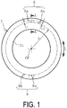
- the engraving 8 is formed on a surface 7a of an annular side plate 7 exemplified in FIG. 1 , which is a component of the tire mold.
- the engraving 8 may be constituted by characters, numbers, designs, or the like and is raised or depressed with respect to the surface 7a.
- the innermost circumferential position of the engraving 8a is a position of radial distance r from an annular center point CP of the side plate 7.
- the engraving 8a has a size equivalent to radial length t.
- the innermost circumferential position of another engraving 8b is also a position of the radial distance r from the center point CP.
- the engraving 8b has a size equivalent to radial length t1 (t > t1).
- the position and the size of the engravings 8 are set separately.
- These engravings 8 may be disposed at a single position on the surface 7a of the side plate 7 or may be disposed at a plurality of positions at appropriate intervals in the circumferential direction L of the side plate 7.
- the surface 7a of the side plate 7 is a curved surface with its dimensions in the thickness direction H varying in accordance with the radial distance, as exemplified in FIG. 2 .
- the radial distance r in a plan view is equivalent to radial distance R, which is a distance along the curved surface of the surface 7a when viewed in the cross section of FIG. 2 .
- R radial distance
- the radial distance r is corrected on the basis of the locus length in the radial direction of the surface 7a of the side plate 7, it becomes radial distance R.
- the radial length t of the engraving 8 in a plan view is corrected on the basis of the locus length in the radial direction of the surface 7a, it becomes radial length T.
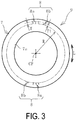
- a two-dimensional image master data 9 of the engravings 8 in a plan view, as exemplified in FIG. 3 is generated using basic data set as a reference.
- the radial component t, t1 (radial length t, t1) and the radial position r of the engraving 8 formed on the surface 7a are corrected on the basis of the locus length in the radial direction of the surface 7a of the side plate 7.
- the innermost circumferential position of the engravings 8 is the radial position R, and the engravings 8 have the radial length T, T1.
- the basic data set as the reference can be design or manufacturing data of the side plate 7, data acquired from a completed, non-defective product, and the like.
- the two-dimensional image master data 9 is processed to rectangularize the data as illustrated in FIG. 4 , for example.
- the X direction corresponds to the circumferential direction L of the side plate 7
- the Y direction corresponds to the radial direction of the side plate 7.
- the method for inspection of the present invention is carried out on the basis of the flow chart exemplified in FIG. 5 .
- the two-dimensional image master data 9 of the engravings 8 in a plan view is generated (step 1).
- an inspection device 1 for engravings in the tire mold of the present invention (hereinafter referred to as "inspection device 1") as exemplified in FIG. 6 is used.
- the inspection device 1 exemplified in FIG. 6 includes a data processing device 2 such as a computer, and a measuring unit 3 configured to take actual measurements of the manufactured side plate 7 and acquire the three-dimensional data of the engravings 8 formed on the surface 7a of the side plate 7.
- the image master data 9 described above is input into the data processing device 2.
- the measuring unit 3 includes an irradiating device 4 configured to irradiate the surface 7a of the side plate 7 with a laser, and a camera device 5.
- the camera device 5 is configured to capture an image of the engravings 8 irradiated by the laser and acquire three-dimensional data of the engravings 8.
- the inspection device 1 includes a rotation mechanism 6 configured to actuate rotational movement of the side plate 7 and the camera device 5 relative to one another about the annular center point CP of the manufactured side plate 7.
- the rotation mechanism 6 is constituted by, for example, a rotational plate 6a on which the side plate 7 is placed and a drive unit 6b configured to drive in rotation the rotational plate 6a.
- the camera device 5 is fixed at a certain position, and the side plate 7 together with the rotational plate 6a move in rotation about the annular center point CP. Images of the engravings 8 are captured while the side plate 7 is rotated in the circumferential direction L to acquire three-dimensional data of the engravings 8 for one revolution of the side plate 7.
- the side plate 7 can be fixed at a certain position and the camera device 5 moved in rotation about the annular center point CP.
- the data processing device 2 substitutes the radial components (radial length) and the thickness components of the acquired three-dimensional data of the engravings 8 for values and converts the data to a greyscale image.
- the image master data 9 is corrected as described above, thus as is the case with the acquired three-dimensional data, the radial component (radial length) and the radial position of the surface 7a of the side plate 7 is corrected on the basis of the actual measurement of the radial locus length of the surface 7a of the side plate 7 to generate two-dimensional image actual measurement data 10 as exemplified in FIG. 7 (step 3). This correction allows for comparison of the image master data 9 and the image actual measurement data 10.
- the data processing device 2 performs comparison processing on the image contours of the image master data 9 and the image actual measurement data 10 as exemplified in FIG. 8 (step 4).
- the comparison processing it is determined whether or not the image shape and the image position of the image actual measurement data 10 is within a tolerable range with respect to the image shape and the image position of the image master data 9.
- the image master data 9 (the letter "X” in FIG. 8 ) and the image actual measurement data 10 (the letter "X” in FIG. 8 ) are aligned so as to overlap.
- the tolerable range in terms of the degree of match of the image shape and the misalignment of the two is preset and input into the data processing device 2.
- the two are determined to be a match and the engravings 8 in the surface 7a of the side plate 7 are determined to be suitable. If the result is that of being outside the tolerable range, the engravings 8 are determined to be unsuitable.
- two-dimensional data is compared. Accordingly, it can be determined whether or not the image shape and the image position of the image actual measurement data 10 is within a tolerable range with respect to the image shape and the image position of the image master data 9 in a reduced inspection time and with high precision. Additionally, inspection of small engravings 8 a few millimeters in size (for example, from 1 mm to 2 mm), that are difficult to determine the suitability of visually, is possible in a reduced inspection time and with high precision.
- the data of the engravings 8 (the engraving 8a for example), which is to be the extracted reference upon comparison processing, can be input into the data processing device 2 as extracted reference engraving data.
- extracted reference engraving corresponding data (engraving 8a) in the image actual measurement data 10 which corresponds to the extracted reference engraving data (engraving 8a)
- preliminary alignment of the images of the image master data 9 and the image actual measurement data 10 can be performed by aligning (aligning in the X direction) the images of the extracted reference engraving data (engraving 8a) and the extracted reference engraving corresponding data (engraving 8a). By performing this rough preliminary alignment automatically with the extracted reference engraving data as an indicator, operation man-hours can be greatly reduced.
- an appropriate engraving 8 such as the largest of the engravings 8 can be employed.
- the data of the engraving 8 in the side plate 7 determined to be suitable is stored in the data processing device 2 and can be used in the next determination of suitability. For example, upon the next determination of suitability, the acquired and generated image actual measurement data 10 of the engraving 8 in the side plate 7 can be compared to the previous image actual measurement data 10 stored in the data processing device 2 to keep track of changes over time. By doing so, an appropriate service life of the side plate 7 can be determined.
Landscapes
- Physics & Mathematics (AREA)
- General Physics & Mathematics (AREA)
- Engineering & Computer Science (AREA)
- Biochemistry (AREA)
- Immunology (AREA)
- Life Sciences & Earth Sciences (AREA)
- Chemical & Material Sciences (AREA)
- Analytical Chemistry (AREA)
- Pathology (AREA)
- General Health & Medical Sciences (AREA)
- Health & Medical Sciences (AREA)
- Computer Vision & Pattern Recognition (AREA)
- Theoretical Computer Science (AREA)
- Quality & Reliability (AREA)
- Signal Processing (AREA)
- Length Measuring Devices By Optical Means (AREA)
- Investigating Materials By The Use Of Optical Means Adapted For Particular Applications (AREA)
Abstract
Description
- The present invention relates to a method and a device for inspecting engravings in a tire mold; and particularly relates to a method and a device for inspecting engravings in a tire mold capable of determining the suitability of engravings formed on a surface of an annular side plate, which is a component of the tire mold, in a reduced time and with high precision.
- Various information, such as tire size, brand name, and design, is marked on the side surface of pneumatic tires. To mark such information on the tire side surface, engravings corresponding to this information are engraved on a surface of an annular side plate, which is a component of a tire mold. Upon manufacture of the side plate, various inspections are carried out, including whether the engravings formed on the surface of the side plate match the preset information, whether the position of the engravings is suitable, and whether the engravings have deteriorated. Such engravings are small being only a few millimeters in size. Thus, visual inspection of the suitability of the engravings requires a great amount of time and effort.
- A method of inspection is known that determines the acceptability of a raised or depressed character string formed on a side surface of a manufactured pneumatic tire (see Patent Document 1). In the method of inspection of this patent document, an image of the raised or depressed character string formed on the tire side surface is captured and an image pattern of the character string is generated. Thereafter, how much the generated image pattern is a match with a preset model pattern is calculated, and this result determines whether the character string is acceptable or not.
- In such a method of inspection, a degree of match is obtained by comparing the three-dimensional data of the raised or depressed character string for inspection against a reference (model pattern) raised or depressed character string three-dimensional data. However, processing the data to obtain a degree of match requires much time, and a high performance data processing machine with high processing speeds is required.
- Patent Document 1: Japanese Unexamined Patent Application Publication No.
2005-246931A - An object of the present invention is to provide a method and a device for inspecting engravings in a tire mold capable of determining the suitability of engravings formed on a surface of an annular side plate, which is a component of the tire mold, in a reduced time and with high precision.
- To achieve the object described above, a method of the present invention for inspecting engravings in a tire mold capable of determining suitability of an engraving formed on a surface of an annular side plate, which is a component of the tire mold, comprises the steps of:
- inputting into a data processing device two-dimensional image master data of an engraving formed on a surface of a side plate in a plan view pregenerated using basic data set as a reference, the image master data having a radial component and a radial position of the engraving corrected on the basis of a locus length in a radial direction of the surface of the side plate;
- acquiring three-dimensional data of the engraving by actual measurement of the manufactured side plate;
- generating two-dimensional image actual measurement data, the image actual measurement data having a radial component and a radial position of the three-dimensional data corrected on the basis of a radial locus length of a surface of the side plate on which actual measurement was performed; and
- determining whether or not an image shape and an image position of the image actual measurement data is within a tolerable range with respect to an image shape and an image position of the image master data via comparison processing of image contours of the image master data and the image actual measurement data by the data processing device.
- A device of the present invention for inspecting engravings in a tire mold capable of determining suitability of an engraving formed on a surface of an annular side plate, which is a component of the tire mold, comprises:
- a data processing device configured to receive two-dimensional image master data of an engraving formed on a surface of a side plate in a plan view using basic data set as a reference, the image master data having a radial component and a radial position of the engraving corrected on the basis of a locus length in a radial direction of the surface of the side plate; and
- a measuring unit configured to acquire three-dimensional data of the engraving by actual measurement of the manufactured side plate; wherein
- According to the present invention, the two-dimensional image master data of the engraving in a plan view is pregenerated using basic data set as a reference. In the image master data, the radial component and the radial position of the engraving formed on the surface are corrected on the basis of the locus length in the radial direction of the surface of the side plate. Comparison of the image contours of the image actual measurement data and the image master data is made possible by the generation of two-dimensional image actual measurement data. The two-dimensional image actual measurement data is generated by acquiring three-dimensional data of the engraving by the actual measurement of the manufactured side plate, and then correcting the radial component and the radial position of the three-dimensional data on the basis of the radial locus length of the surface of the side plate on which actual measurement was performed. By comparing the two-dimensional data by comparison processing, it can be determined whether or not the image shape and the image position of the image actual measurement data is within a tolerable range with respect to the image shape and the image position of the image master data in a reduced inspection time and with high precision. Accordingly, the inspection target engraving can be determined as suitable or not against the master data, which serves as a suitability determination reference.
-
-
FIG. 1 is an explanatory view illustrating in a plan view a manufactured side plate. -
FIG. 2 is an explanatory view illustrating a cross section taken along A-A ofFIG. 1 . -
FIG. 3 is an explanatory view illustrating image master data. -
FIG. 4 is an explanatory view illustrating rectangularized image master data. -
FIG. 5 is a flow chart of the steps of an inspection method of the present invention. -
FIG. 6 is an explanatory view schematically illustrating an inspection device of the present invention. -
FIG. 7 is an explanatory view illustrating corrected image actual measurement data. -
FIG. 8 is an explanatory view illustrating the step of comparison processing of image contours of the image master data ofFIG. 4 and the image actual measurement data ofFIG. 7 . - Below, a method and a device for inspecting engravings in a tire mold of the present invention will be described referencing embodiments illustrated in the drawings.
- The method and the device for inspecting engravings in a tire mold of the present invention are used to determine whether or not an engraving 8 (8a, 8b) is within a tolerable range with respect to a preset reference (image master data 9 described below) and suitable. The
engraving 8 is formed on a surface 7a of anannular side plate 7 exemplified inFIG. 1 , which is a component of the tire mold. -
Various engravings side plate 7. Theengraving 8 may be constituted by characters, numbers, designs, or the like and is raised or depressed with respect to the surface 7a. In a plan view, the innermost circumferential position of the engraving 8a is a position of radial distance r from an annular center point CP of theside plate 7. The engraving 8a has a size equivalent to radial length t. The innermost circumferential position of another engraving 8b is also a position of the radial distance r from the center point CP. The engraving 8b has a size equivalent to radial length t1 (t > t1). The position and the size of theengravings 8 are set separately. Theseengravings 8 may be disposed at a single position on the surface 7a of theside plate 7 or may be disposed at a plurality of positions at appropriate intervals in the circumferential direction L of theside plate 7. - Typically, the surface 7a of the
side plate 7 is a curved surface with its dimensions in the thickness direction H varying in accordance with the radial distance, as exemplified inFIG. 2 . Accordingly, the radial distance r in a plan view is equivalent to radial distance R, which is a distance along the curved surface of the surface 7a when viewed in the cross section ofFIG. 2 . In other words, when the radial distance r is corrected on the basis of the locus length in the radial direction of the surface 7a of theside plate 7, it becomes radial distance R. In a similar manner, when the radial length t of theengraving 8 in a plan view is corrected on the basis of the locus length in the radial direction of the surface 7a, it becomes radial length T. - In the present invention, a two-dimensional image master data 9 of the
engravings 8 in a plan view, as exemplified inFIG. 3 , is generated using basic data set as a reference. In the image master data 9, the radial component t, t1 (radial length t, t1) and the radial position r of theengraving 8 formed on the surface 7a are corrected on the basis of the locus length in the radial direction of the surface 7a of theside plate 7. In the image master data 9, the innermost circumferential position of theengravings 8 is the radial position R, and theengravings 8 have the radial length T, T1. Note that in the image master data 9, the basic data set as the reference can be design or manufacturing data of theside plate 7, data acquired from a completed, non-defective product, and the like. - The two-dimensional image master data 9 is processed to rectangularize the data as illustrated in
FIG. 4 , for example. InFIG. 4 , the X direction corresponds to the circumferential direction L of theside plate 7, and the Y direction corresponds to the radial direction of theside plate 7. - The method for inspection of the present invention is carried out on the basis of the flow chart exemplified in
FIG. 5 . First, as described above, the two-dimensional image master data 9 of theengravings 8 in a plan view is generated (step 1). - Next, actual measurements of the manufactured
side plate 7 are taken, and the three-dimensional data of theengravings 8 is acquired (step 2). Upon actual measurement of theside plate 7, aninspection device 1 for engravings in the tire mold of the present invention (hereinafter referred to as "inspection device 1") as exemplified inFIG. 6 is used. - The
inspection device 1 exemplified inFIG. 6 includes adata processing device 2 such as a computer, and ameasuring unit 3 configured to take actual measurements of the manufacturedside plate 7 and acquire the three-dimensional data of theengravings 8 formed on the surface 7a of theside plate 7. The image master data 9 described above is input into thedata processing device 2. - In this embodiment, the measuring
unit 3 includes anirradiating device 4 configured to irradiate the surface 7a of theside plate 7 with a laser, and a camera device 5. The camera device 5 is configured to capture an image of theengravings 8 irradiated by the laser and acquire three-dimensional data of theengravings 8. - Additionally, the
inspection device 1 includes arotation mechanism 6 configured to actuate rotational movement of theside plate 7 and the camera device 5 relative to one another about the annular center point CP of the manufacturedside plate 7. Therotation mechanism 6 is constituted by, for example, a rotational plate 6a on which theside plate 7 is placed and adrive unit 6b configured to drive in rotation the rotational plate 6a. In this embodiment, the camera device 5 is fixed at a certain position, and theside plate 7 together with the rotational plate 6a move in rotation about the annular center point CP. Images of theengravings 8 are captured while theside plate 7 is rotated in the circumferential direction L to acquire three-dimensional data of theengravings 8 for one revolution of theside plate 7. Theside plate 7 can be fixed at a certain position and the camera device 5 moved in rotation about the annular center point CP. - The
data processing device 2, for example, substitutes the radial components (radial length) and the thickness components of the acquired three-dimensional data of theengravings 8 for values and converts the data to a greyscale image. Here, the image master data 9 is corrected as described above, thus as is the case with the acquired three-dimensional data, the radial component (radial length) and the radial position of the surface 7a of theside plate 7 is corrected on the basis of the actual measurement of the radial locus length of the surface 7a of theside plate 7 to generate two-dimensional imageactual measurement data 10 as exemplified inFIG. 7 (step 3). This correction allows for comparison of the image master data 9 and the imageactual measurement data 10. - Next, the
data processing device 2 performs comparison processing on the image contours of the image master data 9 and the imageactual measurement data 10 as exemplified inFIG. 8 (step 4). In the comparison processing, it is determined whether or not the image shape and the image position of the imageactual measurement data 10 is within a tolerable range with respect to the image shape and the image position of the image master data 9. In other words, the image master data 9 (the letter "X" inFIG. 8 ) and the image actual measurement data 10 (the letter "X" inFIG. 8 ) are aligned so as to overlap. The tolerable range in terms of the degree of match of the image shape and the misalignment of the two is preset and input into thedata processing device 2. - If the result of the comparison of the two is that the image shape and the image position of the image
actual measurement data 10 is within the tolerable range with respect to the image shape and the image position of the image master data 9, the two are determined to be a match and theengravings 8 in the surface 7a of theside plate 7 are determined to be suitable. If the result is that of being outside the tolerable range, theengravings 8 are determined to be unsuitable. - In the comparison processing of the present invention described above, two-dimensional data is compared. Accordingly, it can be determined whether or not the image shape and the image position of the image
actual measurement data 10 is within a tolerable range with respect to the image shape and the image position of the image master data 9 in a reduced inspection time and with high precision. Additionally, inspection ofsmall engravings 8 a few millimeters in size (for example, from 1 mm to 2 mm), that are difficult to determine the suitability of visually, is possible in a reduced inspection time and with high precision. - For example, in the image master data 9, the data of the engravings 8 (the
engraving 8a for example), which is to be the extracted reference upon comparison processing, can be input into thedata processing device 2 as extracted reference engraving data. Upon comparison processing of the image contours of the image master data 9 and the imageactual measurement data 10, extracted reference engraving corresponding data (engraving 8a) in the imageactual measurement data 10, which corresponds to the extracted reference engraving data (engraving 8a), is automatically extracted by thedata processing device 2. Additionally, preliminary alignment of the images of the image master data 9 and the imageactual measurement data 10 can be performed by aligning (aligning in the X direction) the images of the extracted reference engraving data (engraving 8a) and the extracted reference engraving corresponding data (engraving 8a). By performing this rough preliminary alignment automatically with the extracted reference engraving data as an indicator, operation man-hours can be greatly reduced. As the extracted reference engraving data, for example, anappropriate engraving 8 such as the largest of theengravings 8 can be employed. - After the preliminary alignment of the images of the image master data 9 and the image
actual measurement data 10 described above, a detailed final alignment (alignment in the Y direction and small adjustments to the alignment in the X direction) of the images of theengravings - The data of the
engraving 8 in theside plate 7 determined to be suitable is stored in thedata processing device 2 and can be used in the next determination of suitability. For example, upon the next determination of suitability, the acquired and generated imageactual measurement data 10 of theengraving 8 in theside plate 7 can be compared to the previous imageactual measurement data 10 stored in thedata processing device 2 to keep track of changes over time. By doing so, an appropriate service life of theside plate 7 can be determined. -
- 1
- Inspection device
- 2
- Data processing device
- 3
- Measuring unit
- 4
- Irradiating device
- 5
- Camera device
- 6
- Rotation mechanism
- 6a
- Rotational plate
- 6b
- Drive unit
- 7
- Side plate
- 7a
- Surface
- 8, 8a, 8b
- Engraving
- 9
- Image master data
- 10
- Image actual measurement data
- CL
- Annular center point
whether or not an image shape and an image position of the image actual measurement data is within a tolerable range with respect to an image shape and an image position of the image master data is determined via comparison processing of image contours of the image master data and the image actual measurement data by the data processing device.
Claims (6)
- A method for inspecting engravings in a tire mold capable of determining suitability of an engraving formed on a surface of an annular side plate, which is a component of the tire mold, the method comprising the steps of:inputting into a data processing device two-dimensional image master data of an engraving formed on a surface of a side plate in a plan view pregenerated using basic data set as a reference, the image master data having a radial component and a radial position of the engraving corrected on the basis of a locus length in a radial direction of the surface of the side plate;acquiring three-dimensional data of the engraving by actual measurement of the manufactured side plate;generating two-dimensional image actual measurement data, the image actual measurement data having a radial component and a radial position of the three-dimensional data corrected on the basis of a radial locus length of a surface of the side plate on which actual measurement was performed; anddetermining whether or not an image shape and an image position of the image actual measurement data is within a tolerable range with respect to an image shape and an image position of the image master data via comparison processing of image contours of the image master data and the image actual measurement data by the data processing device.
- The method for inspecting engravings in a tire mold according to claim 1, wherein
data of an engraving to be a reference in the image master data is input into the data processing device as reference engraving data, and
upon the comparison processing of the image contours of the image master data and the image actual measurement data, reference engraving corresponding data in the image actual measurement data corresponding to the reference engraving data is automatically extracted by the data processing device, and further comprising the step ofperforming preliminary alignment of images of the image master data and the image actual measurement data by alignment processing of images of the reference engraving data and the reference engraving corresponding data. - The method for inspecting engravings in a tire mold according to claim 2, further comprising the step ofperforming final alignment processing of the images of the engravings of the image master data and the image actual measurement data after the preliminary alignment of the images of the image master data and the image actual measurement data.
- A device for inspecting engravings in a tire mold capable of determining suitability of an engraving formed on a surface of an annular side plate, which is a component of the tire mold, the device comprising:a data processing device configured to receive two-dimensional image master data of an engraving formed on a surface of a side plate in a plan view using basic data set as a reference, the image master data having a radial component and a radial position of the engraving corrected on the basis of a locus length in a radial direction of the surface of the side plate; anda measuring unit configured to acquire three-dimensional data of the engraving by actual measurement of the manufactured side plate; wherein two-dimensional image actual measurement data is generated by the data processing device, the image actual measurement data having a radial component and a radial position of the three-dimensional data corrected on the basis of a radial locus length of a surface of the side plate on which actual measurement was performed; andwhether or not an image shape and an image position of the image actual measurement data is within a tolerable range with respect to an image shape and an image position of the image master data is determined via comparison processing of image contours of the image master data and the image actual measurement data by the data processing device.
- The device for inspecting engravings in a tire mold according to claim 4, wherein
the measuring unit includes an irradiating device configured to irradiate the surface of the manufactured side plate with a laser, and a camera device configured to acquire the three-dimensional data by capturing an image of the engraving irradiated by the laser. - The device for inspecting engravings in a tire mold according to claim 5, further comprisinga rotation mechanism configured to actuate rotational movement of the side plate and the camera device relative to one another about an annular center point of the manufactured side plate.
Applications Claiming Priority (2)
| Application Number | Priority Date | Filing Date | Title |
|---|---|---|---|
| JP2014078609 | 2014-04-07 | ||
| PCT/JP2015/060140 WO2015156172A1 (en) | 2014-04-07 | 2015-03-31 | Tire mold engraving inspection method and device |
Publications (2)
| Publication Number | Publication Date |
|---|---|
| EP3130886A1 true EP3130886A1 (en) | 2017-02-15 |
| EP3130886A4 EP3130886A4 (en) | 2018-05-30 |
Family
ID=54287749
Family Applications (1)
| Application Number | Title | Priority Date | Filing Date |
|---|---|---|---|
| EP15777214.6A Withdrawn EP3130886A4 (en) | 2014-04-07 | 2015-03-31 | Tire mold engraving inspection method and device |
Country Status (5)
| Country | Link |
|---|---|
| US (1) | US10451408B2 (en) |
| EP (1) | EP3130886A4 (en) |
| JP (1) | JP6614137B2 (en) |
| CN (1) | CN106104201B (en) |
| WO (1) | WO2015156172A1 (en) |
Families Citing this family (8)
| Publication number | Priority date | Publication date | Assignee | Title |
|---|---|---|---|---|
| US10063837B2 (en) * | 2013-07-25 | 2018-08-28 | TIREAUDIT.COM, Inc. | System and method for analysis of surface features |
| KR102534392B1 (en) | 2014-12-22 | 2023-05-19 | 피렐리 타이어 소시에떼 퍼 아찌오니 | Apparatus for controlling tyres in a production line |
| RU2696343C2 (en) * | 2014-12-22 | 2019-08-01 | Пирелли Тайр С.П.А. | Method and device for monitoring tires on production line |
| US11472234B2 (en) | 2016-03-04 | 2022-10-18 | TIREAUDIT.COM, Inc. | Mesh registration system and method for diagnosing tread wear |
| US10789773B2 (en) | 2016-03-04 | 2020-09-29 | TIREAUDIT.COM, Inc. | Mesh registration system and method for diagnosing tread wear |
| JP7058170B2 (en) * | 2018-05-02 | 2022-04-21 | Toyo Tire株式会社 | Tire mold side plate inspection method |
| CN110375645B (en) * | 2019-07-04 | 2021-09-28 | 成都绝影智能科技有限公司 | Character size detection method and device |
| CN113686248B (en) * | 2021-08-23 | 2024-06-18 | 北京京东乾石科技有限公司 | Offset measurement device, method, electronic device and readable storage medium |
Family Cites Families (19)
| Publication number | Priority date | Publication date | Assignee | Title |
|---|---|---|---|---|
| JP2003240521A (en) * | 2002-02-21 | 2003-08-27 | Bridgestone Corp | Method and apparatus for inspection of external appearance and shape of specimen |
| JP2004082692A (en) * | 2002-06-28 | 2004-03-18 | Ngk Insulators Ltd | Flap vent piece installation assembly, flap vent piece installation structure and installation method, and tire molding die |
| JP2005246931A (en) * | 2004-03-08 | 2005-09-15 | Sumitomo Rubber Ind Ltd | Tire design support system |
| JP4679073B2 (en) * | 2004-05-18 | 2011-04-27 | 株式会社ブリヂストン | Tire unevenness pattern inspection method and tire unevenness pattern inspection apparatus |
| JP4881584B2 (en) * | 2005-06-28 | 2012-02-22 | 株式会社ブリヂストン | How to create master data for inspection of uneven figures |
| US7177740B1 (en) * | 2005-11-10 | 2007-02-13 | Beijing University Of Aeronautics And Astronautics | Method and apparatus for dynamic measuring three-dimensional parameters of tire with laser vision |
| US20070185610A1 (en) * | 2005-11-10 | 2007-08-09 | Hugo Salamanca | Robot system and method for the application of dislodging material and pin positioning in casting wheels |
| JP5124997B2 (en) * | 2006-06-13 | 2013-01-23 | 横浜ゴム株式会社 | Tire mold side plate inspection method and inspection apparatus, tire mold side plate type determination method and determination apparatus, tire mold processing step inspection method and inspection apparatus |
| JP4977415B2 (en) * | 2006-07-21 | 2012-07-18 | 株式会社ブリヂストン | Apparatus and method for creating reference shape data for tire inspection |
| JP4512578B2 (en) * | 2006-10-27 | 2010-07-28 | 株式会社ブリヂストン | Separation filter determination device and tire inspection device |
| ES2464867T3 (en) * | 2007-07-30 | 2014-06-04 | Snap-On Equipment Srl A Unico Socio | Procedure and apparatus for determining the geometric dimensions of a vehicle wheel |
| EP2023078B1 (en) * | 2007-08-06 | 2017-06-14 | Kabushiki Kaisha Kobe Seiko Sho | Tire shape measuring system |
| ATE545917T1 (en) | 2007-12-19 | 2012-03-15 | Michelin Soc Tech | METHOD FOR PROCESSING A THREE-DIMENSIONAL IMAGE OF A TIRE SURFACE FOR ITS USE IN CHECKING SUCH SURFACE |
| EP2634529B1 (en) * | 2008-06-04 | 2014-12-24 | Kabushiki Kaisha Kobe Seiko Sho | Tire shape inspection method and tire shape inspection device |
| JP5371848B2 (en) * | 2009-12-07 | 2013-12-18 | 株式会社神戸製鋼所 | Tire shape inspection method and tire shape inspection device |
| FR2966956B1 (en) * | 2010-10-27 | 2012-12-14 | Michelin Soc Tech | METHOD OF PRE-PROCESSING A DIMENSIONAL IMAGE OF THE SURFACE OF A TIRE USING SUCCESSIVE B-SPLINE DEFORMATIONS |
| JP5882730B2 (en) * | 2011-12-28 | 2016-03-09 | 株式会社ブリヂストン | Appearance inspection apparatus and appearance inspection method |
| JP6126450B2 (en) * | 2013-04-25 | 2017-05-10 | 株式会社ブリヂストン | Inspection device |
| JP5775132B2 (en) * | 2013-11-01 | 2015-09-09 | 株式会社ブリヂストン | Tire inspection equipment |
-
2015
- 2015-03-31 JP JP2016512679A patent/JP6614137B2/en active Active
- 2015-03-31 WO PCT/JP2015/060140 patent/WO2015156172A1/en not_active Ceased
- 2015-03-31 EP EP15777214.6A patent/EP3130886A4/en not_active Withdrawn
- 2015-03-31 CN CN201580013311.4A patent/CN106104201B/en not_active Expired - Fee Related
- 2015-03-31 US US15/302,946 patent/US10451408B2/en active Active
Also Published As
| Publication number | Publication date |
|---|---|
| CN106104201A (en) | 2016-11-09 |
| JP6614137B2 (en) | 2019-12-04 |
| WO2015156172A1 (en) | 2015-10-15 |
| US10451408B2 (en) | 2019-10-22 |
| US20170030709A1 (en) | 2017-02-02 |
| EP3130886A4 (en) | 2018-05-30 |
| CN106104201B (en) | 2019-12-24 |
| JPWO2015156172A1 (en) | 2017-04-13 |
Similar Documents
| Publication | Publication Date | Title |
|---|---|---|
| US10451408B2 (en) | Method and device for inspecting engravings in tire mold | |
| CN105723181B (en) | tire inspection device | |
| CN110785248B (en) | Head system calibration of a power radiation source of an additive manufacturing device | |
| CN103038601B (en) | Tire shape inspection method and tire shape inspection device | |
| EP2789970B1 (en) | Tire shape inspection method and tire shape inspection apparatus | |
| US8452072B2 (en) | Method and apparatus for inspecting tire shape | |
| WO2005111540A1 (en) | Tire projection-and-recess figure examining method and tire projection-and-recess figure examining device | |
| JP6126450B2 (en) | Inspection device | |
| CN118829846A (en) | Surface shape measuring device | |
| US8086019B2 (en) | Method of creating master data used for inspecting concave-convex figure | |
| JP5124997B2 (en) | Tire mold side plate inspection method and inspection apparatus, tire mold side plate type determination method and determination apparatus, tire mold processing step inspection method and inspection apparatus | |
| JP7058170B2 (en) | Tire mold side plate inspection method | |
| CN103493096B (en) | The analysis of the digital picture of tire inner surface and the processing of pseudo-measurement point | |
| KR101335385B1 (en) | An apparatus for a carved seal of tire and an inspection of tire marking part depth | |
| KR102178046B1 (en) | Pattern evaluation device | |
| JP2020151744A (en) | Laser engraving device, tabbed can lid manufacturing device and manufacturing method | |
| JP2021071939A (en) | Stamp discrimination apparatus and method | |
| WO2021153408A1 (en) | Printing plate inspection device and inspection method | |
| JP2016001165A (en) | Tire visual inspection method |
Legal Events
| Date | Code | Title | Description |
|---|---|---|---|
| STAA | Information on the status of an ep patent application or granted ep patent |
Free format text: STATUS: THE INTERNATIONAL PUBLICATION HAS BEEN MADE |
|
| PUAI | Public reference made under article 153(3) epc to a published international application that has entered the european phase |
Free format text: ORIGINAL CODE: 0009012 |
|
| STAA | Information on the status of an ep patent application or granted ep patent |
Free format text: STATUS: REQUEST FOR EXAMINATION WAS MADE |
|
| 17P | Request for examination filed |
Effective date: 20161104 |
|
| AK | Designated contracting states |
Kind code of ref document: A1 Designated state(s): AL AT BE BG CH CY CZ DE DK EE ES FI FR GB GR HR HU IE IS IT LI LT LU LV MC MK MT NL NO PL PT RO RS SE SI SK SM TR |
|
| AX | Request for extension of the european patent |
Extension state: BA ME |
|
| RIN1 | Information on inventor provided before grant (corrected) |
Inventor name: TANAKA, TATSUNORI Inventor name: TADA, HIROTARO Inventor name: MOTOMIYA, SYOUNOSUKE |
|
| DAV | Request for validation of the european patent (deleted) | ||
| DAX | Request for extension of the european patent (deleted) | ||
| RIN1 | Information on inventor provided before grant (corrected) |
Inventor name: MOTOMIYA, SHONOSUKE Inventor name: TANAKA, TATSUNORI Inventor name: TADA, HIROTARO |
|
| RIC1 | Information provided on ipc code assigned before grant |
Ipc: G06T 7/33 20170101ALI20180418BHEP Ipc: G01N 21/88 20060101ALI20180418BHEP Ipc: G01N 21/95 20060101ALI20180418BHEP Ipc: G01N 21/956 20060101ALI20180418BHEP Ipc: G06T 7/00 20170101ALI20180418BHEP Ipc: G01B 11/24 20060101AFI20180418BHEP |
|
| A4 | Supplementary search report drawn up and despatched |
Effective date: 20180426 |
|
| STAA | Information on the status of an ep patent application or granted ep patent |
Free format text: STATUS: EXAMINATION IS IN PROGRESS |
|
| 17Q | First examination report despatched |
Effective date: 20200602 |
|
| STAA | Information on the status of an ep patent application or granted ep patent |
Free format text: STATUS: THE APPLICATION IS DEEMED TO BE WITHDRAWN |
|
| 18D | Application deemed to be withdrawn |
Effective date: 20211001 |