EP3130860A1 - Air conditioner - Google Patents
Air conditioner Download PDFInfo
- Publication number
- EP3130860A1 EP3130860A1 EP14888581.7A EP14888581A EP3130860A1 EP 3130860 A1 EP3130860 A1 EP 3130860A1 EP 14888581 A EP14888581 A EP 14888581A EP 3130860 A1 EP3130860 A1 EP 3130860A1
- Authority
- EP
- European Patent Office
- Prior art keywords
- air
- air duct
- duct wall
- outlet
- case
- Prior art date
- Legal status (The legal status is an assumption and is not a legal conclusion. Google has not performed a legal analysis and makes no representation as to the accuracy of the status listed.)
- Granted
Links
Images



Classifications
-
- F—MECHANICAL ENGINEERING; LIGHTING; HEATING; WEAPONS; BLASTING
- F24—HEATING; RANGES; VENTILATING
- F24F—AIR-CONDITIONING; AIR-HUMIDIFICATION; VENTILATION; USE OF AIR CURRENTS FOR SCREENING
- F24F13/00—Details common to, or for air-conditioning, air-humidification, ventilation or use of air currents for screening
- F24F13/20—Casings or covers
-
- F—MECHANICAL ENGINEERING; LIGHTING; HEATING; WEAPONS; BLASTING
- F24—HEATING; RANGES; VENTILATING
- F24F—AIR-CONDITIONING; AIR-HUMIDIFICATION; VENTILATION; USE OF AIR CURRENTS FOR SCREENING
- F24F1/00—Room units for air-conditioning, e.g. separate or self-contained units or units receiving primary air from a central station
- F24F1/0007—Indoor units, e.g. fan coil units
- F24F1/0043—Indoor units, e.g. fan coil units characterised by mounting arrangements
- F24F1/0047—Indoor units, e.g. fan coil units characterised by mounting arrangements mounted in the ceiling or at the ceiling
-
- F—MECHANICAL ENGINEERING; LIGHTING; HEATING; WEAPONS; BLASTING
- F24—HEATING; RANGES; VENTILATING
- F24F—AIR-CONDITIONING; AIR-HUMIDIFICATION; VENTILATION; USE OF AIR CURRENTS FOR SCREENING
- F24F11/00—Control or safety arrangements
- F24F11/30—Control or safety arrangements for purposes related to the operation of the system, e.g. for safety or monitoring
-
- F—MECHANICAL ENGINEERING; LIGHTING; HEATING; WEAPONS; BLASTING
- F24—HEATING; RANGES; VENTILATING
- F24F—AIR-CONDITIONING; AIR-HUMIDIFICATION; VENTILATION; USE OF AIR CURRENTS FOR SCREENING
- F24F13/00—Details common to, or for air-conditioning, air-humidification, ventilation or use of air currents for screening
- F24F13/08—Air-flow control members, e.g. louvres, grilles, flaps or guide plates
-
- F—MECHANICAL ENGINEERING; LIGHTING; HEATING; WEAPONS; BLASTING
- F24—HEATING; RANGES; VENTILATING
- F24F—AIR-CONDITIONING; AIR-HUMIDIFICATION; VENTILATION; USE OF AIR CURRENTS FOR SCREENING
- F24F13/00—Details common to, or for air-conditioning, air-humidification, ventilation or use of air currents for screening
- F24F13/08—Air-flow control members, e.g. louvres, grilles, flaps or guide plates
- F24F13/10—Air-flow control members, e.g. louvres, grilles, flaps or guide plates movable, e.g. dampers
- F24F13/14—Air-flow control members, e.g. louvres, grilles, flaps or guide plates movable, e.g. dampers built up of tilting members, e.g. louvre
-
- F—MECHANICAL ENGINEERING; LIGHTING; HEATING; WEAPONS; BLASTING
- F24—HEATING; RANGES; VENTILATING
- F24F—AIR-CONDITIONING; AIR-HUMIDIFICATION; VENTILATION; USE OF AIR CURRENTS FOR SCREENING
- F24F13/00—Details common to, or for air-conditioning, air-humidification, ventilation or use of air currents for screening
- F24F13/02—Ducting arrangements
- F24F13/06—Outlets for directing or distributing air into rooms or spaces, e.g. ceiling air diffuser
- F24F2013/0616—Outlets that have intake openings
Definitions
- the present invention relates to an air conditioner.
- an airflow direction flap is arranged at a vicinity of an air outlet, and the airflow direction flap guides a direction of a current of blown-out air.
- a current of air flowing along a longitudinal end portion of the airflow direction flap is liable to flow weakly, and liable to take the air therein from an inside of a room, thereby easily flowing upward to a ceiling side.
- the current of the air flowing along the longitudinal end portion of the airflow direction flap may cause smudging of the ceiling.
- a related-art ceiling-embedded air conditioner is disclosed in, for example, Patent Literature 1.
- a chord length of a longitudinal end portion of an airflow direction flap is reduced, and a current of blown-out air flowing along the longitudinal end portion of the airflow direction flap is directed downward, thereby preventing smudging of a ceiling.
- the present invention has been made in order to solve the above-mentioned problem, and has an object to provide an air conditioner capable of reducing smudging caused by a current of air flowing along a longitudinal end portion of an airflow direction flap while preventing short cycling from easily occurring in the current of the air flowing along the longitudinal end portion of the airflow direction flap.
- an air conditioner including: at least one air inlet and at least one air outlet formed in a lower portion of the air conditioner; a wall portion defining one blowing air duct having the one air outlet as an outlet; an airflow direction flap arranged in the one air outlet; an air sending unit configured to generate a flow of air that is sucked through the air inlet and blown out through the air outlet; and a heat exchanger arranged in a flow passage of the air that is sucked through the air inlet and blown out through the air outlet, the wall portion including an inner air duct wall and an outer air duct wall, in which, in plan view, the outer air duct wall is at a position more distant from the heat exchanger than the inner air duct wall, and in which, on a plane on upstream of the airflow direction flap, a distance between a center portion of the outer air duct wall in a longitudinal direction of the blowing air duct and a center portion
- the air conditioner of the present invention it is possible to reduce smudging caused by the current of the air flowing along the longitudinal end portion of the airflow direction flap while preventing short cycling from easily occurring in the current of the air flowing along the longitudinal end portion of the airflow direction flap.
- FIG. 1 is a side view for illustrating the internal structure of an air conditioner according to a first embodiment of the present invention.
- FIG. 2 is a top view for illustrating an air outlet of the air conditioner according to the first embodiment.
- FIG. 3 is a view for illustrating a blowing air duct of the air conditioner according to the first embodiment when seen from a direction indicated by the arrows III of FIG. 2 .
- FIG. 4 is a view for illustrating the blowing air duct of the air conditioner according to the first embodiment when seen from a direction indicated by the arrows IV of FIG. 2 .
- the air conditioner according to the first embodiment corresponds to an indoor unit of a so-called package air conditioner.
- FIG. 1 is an illustration of a state in which most part of a case 3 of an air conditioner 1 is embedded on a back side (side opposite to a room) of a ceiling 5 of the room and a lower part of the case 3 faces the inside of the room.
- the air conditioner according to the present invention has at least one air inlet and at least one air outlet formed in a lower portion thereof. Further, the air conditioner according to the present invention includes a wall portion defining a blowing air duct having one air outlet as an outlet, and an airflow direction flap arranged in one air outlet. As one example, the air conditioner 1 according to the first embodiment has four air inlets 7 and one air outlet 9 formed in a lower portion thereof. Further, the air conditioner 1 according to the first embodiment includes four wall portions 11 and four airflow direction flaps 13. One wall portion 11 defines one blowing air duct 15 having one air outlet 9 as an outlet. One airflow direction flap 13 is arranged in the one air outlet 9.
- the four air outlets 9, the four wall portions 11, the four airflow direction flaps 13, and the four blowing air ducts 15 are arranged, and each group of the four components has the same configuration. Accordingly, in the following, one of the air outlets 9, one of the wall portions 11, one of the airflow direction flaps 13, and one of the blowing air ducts 15 are described.
- a centrifugal fan 17 and a heat exchanger 19 are housed in a case 3.
- the centrifugal fan 17 serves as an air sending unit configured to generate a flow of air that is sucked into the case 3 through the air inlet 7 and blown out to a target space (room) through the air outlet 9.
- the heat exchanger 19 is arranged in such a flow passage of the air.
- the case 3 includes a top panel 3a having a rectangular shape in plan view, and four side panels 3b extending downward from four sides of the top panel 3a.
- the case 3 is such a box body that an upper end surface of a rectangular tube body defined by the four side panels 3b is closed by the top panel 3a.
- a panel 21 is mounted on the case 3 in a freely removable manner.
- the panel 21 is a design panel (decorative panel).
- a panel air inlet 21b of a grille type is formed in the vicinity of a center of the panel 21.
- a filter 23 is arranged on downstream of (above) the panel air inlet 21b, and is configured to remove dust in the air passing through a grille portion of the panel air inlet 21b.
- the panel 21 and the panel air inlet 21b each have a rectangular outer edge in plan view.
- the four panel air outlets 21a are formed in accordance with the structure in which the panel 21 and the panel air inlet 21b each have the outer edge along four sides thereof, and the respective panel air outlets 21a are arranged, except for corner portions, so as to extend along the corresponding sides of the panel 21 and the panel air inlet 21b. Further, the four panel air outlets 21a are positioned so as to surround the panel air inlet 21b.
- the panel air inlet 21b corresponds to the above-mentioned air inlet 7, and the four panel air outlets 21a correspond to the above-mentioned air outlets 9. Further, the panel air outlets 21a (air outlets 9) and the blowing air ducts 15 extend along the above-mentioned corresponding sides of the panel 21 and the panel air inlet 21b. In plan view, a direction extended from each of the corresponding sides is referred to as a longitudinal direction, and a direction orthogonal to the longitudinal direction is referred to as a transverse direction. As one example, in the panel air outlet 21a (air outlet 9) and the blowing air duct 15 illustrated in FIG. 2 , a horizontal direction of the drawing sheet of FIG. 2 corresponds to the longitudinal direction, and a vertical direction of the drawing sheet of FIG. 2 corresponds to the transverse direction.
- a fan motor 25 is arranged at a center portion of the inside of the case 3.
- the fan motor 25 is supported by a lower surface of the top panel 3a of the case 3 (at an inner space side of the case).
- the centrifugal fan 17 is fixed to a rotation shaft of the fan motor 25, which extends downward.
- a bellmouth 27 that defines a suction air duct extending from the panel air inlet 21b toward the centrifugal fan 17 is arranged between the centrifugal fan 17 and the filter 23.
- the centrifugal fan 17 is configured to suck the air into the case 3 through the panel air inlet 21b, and cause the air to flow out to the inside of the room being the target space through the panel air outlet 21a.
- the heat exchanger 19 is arranged at a radially outer side of the centrifugal fan 17.
- the heat exchanger 19 is arranged in the flow passage of the air generated in the case 3 by the centrifugal fan 17, and is configured to exchange heat between the air and refrigerant.
- the heat exchanger 19 includes a plurality of fins arranged at predetermined intervals in a horizontal direction, and heat transfer pipes passing through the fins.
- the heat transfer pipes are connected to a known outdoor unit (not shown) through a connection pipe so that cooled or heated refrigerant is supplied to the heat exchanger 19.
- the structures and modes of the centrifugal fan 17, the bellmouth 27, and the heat exchanger 19 are not particularly limited, but known structures and modes are employed in the first embodiment.
- every blowing air duct 15 is defined by one corresponding wall portion 11.
- the wall portion 11 includes a portion formed in the case 3, and a portion formed in the panel 21.
- the above-mentioned panel air outlet 21a is an outlet of the blowing air duct 15 formed in the panel 21, and an outlet of the blowing air duct 15 formed in the case 3 is a case air outlet 31.
- the case 3 has the case air outlet 31 formed in an interface with the panel 21.
- a plane illustrated in FIG. 2 is a plane containing the case air outlet 31, and is a plane flush with the line indicated by reference symbol II of FIG. 3 and FIG. 4 .
- the airflow direction flap 13 is positioned on downstream of the case air outlet 31.
- the airflow direction flap 13 vertically extends astride the panel air inlet 21b (air inlet 7). Further, a chord length of the airflow direction flap 13 is constant in the longitudinal direction.
- the air conditioner according to the present invention has at least one panel air outlet and at least one case air outlet.
- the air conditioner 1 according to the first embodiment has four panel air outlets 21a and four case air outlets 31.
- the wall portion according to the present invention at least includes an inner air duct wall and an outer air duct wall.
- one wall portion 11 includes one inner air duct wall 41, one outer air duct wall 43, and two side walls 45.
- Each of the two side walls 45 extends so as to connect a corresponding end portion of the inner air duct wall 41 and a corresponding end portion of the outer air duct wall 43 to each other.
- the blowing air duct 15 defined by the inner air duct wall 41, the outer air duct wall 43, and the two side walls 45 has substantially a rectangular shape.
- the inner air duct wall 41 and the outer air duct wall 43 extend substantially in parallel to each other.
- the outer air duct wall 43 is more distant from the heat exchanger 19 than the inner air duct wall 41.
- a distance (transverse interval) D1 between a center portion 43a of the outer air duct wall 43 in the longitudinal direction of the blowing air duct 15 and a center portion 41a of the inner air duct wall 41 in the longitudinal direction of the blowing air duct 15 is smaller than a distance (transverse interval) D2 between each side portion 43b of the longitudinal center portion of the outer air duct wall 43 and each side portion 41b of the longitudinal center portion of the inner air duct wall 41.
- the protruding portion 51 is formed on the longitudinal center portion 43a of the outer air duct wall 43.
- the protrudingportion 51 protrudes toward the inner air duct wall 41, and is positioned on the upstream of the airflow direction flap 13. Further, the protruding portion 51 is present on a portion of the case 3 defining the case air outlet 31.
- the distance (transverse interval) D1 between the protruding portion 51 of the outer air duct wall 43 and the inner air duct wall 41 is smaller than the distance (transverse interval) D2 between each side portion of the protruding portion 51 of the outer air duct wall 43 and the inner air duct wall 41.
- the distance D1 between the center portion of the outer air duct wall in the longitudinal direction of the blowing air duct and the center portion of the inner air duct wall in the longitudinal direction of the blowing air duct is smaller than the distance (transverse interval) D2 between each side portion of the longitudinal center portion of the outer air duct wall and each side portion of the longitudinal center portion of the inner air duct wall. Accordingly, a longitudinal center portion of the blowing air duct is narrower than each side portion of the longitudinal center portion of the blowing air duct. This configuration increases a current of air flowing out of the heat exchanger and then flowing into each side portion of the longitudinal center portion of the blowing air duct, and increases air velocity at a longitudinal endportion of the air outlet.
- the prevention of smudging depends on the configuration of the wall portion on the upstream of the airflow direction flap, but no requirement is imposed on use of the airflow direction flap that includes a longitudinal end portion having a chord length smaller than a chord length of a longitudinal center portion thereof. Accordingly, while preventing short cycling from easily occurring in the current of the air flowing along the longitudinal end portion of the airflow direction flap, it is possible to reduce smudging caused by the current of the air flowing along the longitudinal end portion of the airflow direction flap.
- the current of the air cannot flow along the airflow direction flap so that the blown-out air is liable to be directed downward of an outlet angle of the airflow direction flap.
- the protruding portion 51 is formed on the longitudinal center portion 43a of the outer air duct wall 43.
- the current of the air is caused to flow into the blowing air duct from directly above the airflow direction flap, and air velocity on a surface of the airflow direction flap is increased, thereby being capable of easily obtaining an angle of blown-out air approximate to a vane outlet angle.
- FIG. 5 is a view for illustrating the second embodiment in the same manner as that of FIG. 2
- FIG. 6 is a view for illustrating the second embodiment in the same manner as that of FIG. 4
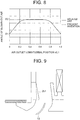
- FIG. 7 is a graph for showing a relationship according to the second embodiment between a length ratio of L2/L1 and an angle of a current of blown-out air flowing out along the longitudinal center portion of the airflow direction flap.
- FIG. 8 is a graph for showing a comparison between the related art and the second embodiment regarding the angle of the current of the blown-out air at a longitudinal position of the airflow direction flap.
- a longitudinal length L2 of a protruding portion 151 of the outer air duct wall 43 is equal to or larger than one third of a longitudinal length L1 of the outer air duct wall 43 itself.
- the protruding portion 151 has the same configuration as that of the above-mentioned protruding portion 51 except for the longitudinal length.
- the current of the air flowing along the longitudinal end portion of the air outlet flows more weakly than the current of the air flowing along the longitudinal center portion of the air outlet. Accordingly, as indicated by the dotted arrows F1 of FIG. 6 , the current of the air flowing along the longitudinal end portion of the air outlet flows along the outer air duct wall of the panel 21, thereby being capable of obtaining an angle ⁇ 1 of blown-out air flowing along the outlet angle of the airflow direction flap 13 (assuming that an angle of horizontal blowing parallel to the ceiling 5 is set zero).
- the angle ⁇ 1 of a current of the blown-out air flowing along the longitudinal endportion of the air outlet is referredto as a non-smudging critical angle (minimum angle causing no smudging (angle most approximate to an angle enabling horizontal blowing without causing smudging)).
- the current of the air flowing along the longitudinal center portion of the air outlet flows strongly. Accordingly, as indicated by the dotted arrows F2 of FIG. 6 , the current of the air flowing along the longitudinal center portion of the air outlet flows along the outer air duct wall of the case, but cannot flow along the airflow direction flap, with the result that the blown-out air is liable to be directed downward of the outlet angle of the airflow direction flap, thereby forming an angle 2 of blown-out air larger than the angle ⁇ 1 of the blown-out air.
- the second embodiment as shown in FIG.
- the protruding portion 151 is formed to satisfy a condition that the length ratio of L2/L1 is equal to or larger than one third.
- the current of the blown-out air flowing along the longitudinal center portion of the air outlet forms the angle ⁇ 1 along the outlet angle of the airflow direction flap 13.
- FIG. 8 over an entire longitudinal region of the air outlet (0 ⁇ x ⁇ L1, that is, 0 ⁇ x/L1 ⁇ 1), it is possible to obtain the constant angle ⁇ 1 of the blown-out air along the outlet angle of the airflow direction flap 13. Consequently, the angle of the blown-out air can be uniformized to the non-smudging critical angle over the entire longitudinal region of the air outlet.
- FIG. 9 is a view for illustrating the third embodiment in the same manner as that of FIG. 3 .
- a protruding height of a protruding portion 251 increases toward downstream of the blowing air duct.
- an air duct width of the blowing air duct in the transverse direction gradually decreases.
- FIG. 10 is a view for illustrating a fourth embodiment of the present invention in the same manner as that of FIG. 2 .
- the air conditioner according to the third embodiment has the same configuration as that of any one of the above-mentioned first to third embodiments except for parts to be described or limited later.
- a longitudinal length of a protruding portion 351 decreases in a stepped manner toward a distal end of the protruding portion 251.
- FIG. 11 is a view for illustrating a fifth embodiment of the present invention in the same manner as that of FIG. 2 .
- the air conditioner according to the fifth embodiment has the same configuration as that of any one of the above-mentioned first to third embodiments except for parts to be described or limited later.
- a longitudinal length of a protruding portion 451 decreases in a continuous manner toward a distal end of the protruding portion 351.
- FIG. 12 is a view for illustrating a sixth embodiment of the present invention in the same manner as that of FIG. 2 .
- the air conditioner according to the sixth embodiment has the same configuration as that of any one of the above-mentioned first to fifth embodiments except for parts to be described or limited later.
- a protruding portion 551 is prepared separately from the outer air duct wall, and is mounted onto the outer air duct wall.
- FIG. 12 is an illustration of an example when the protruding portion according to the first embodiment is prepared as a separate member, but the sixth embodiment is not limited thereto.
- the sixth embodiment may be carried out as a mode of preparing the protruding portion according to each of the second to fifth embodiments as a separate member.
Landscapes
- Engineering & Computer Science (AREA)
- Chemical & Material Sciences (AREA)
- Combustion & Propulsion (AREA)
- Mechanical Engineering (AREA)
- General Engineering & Computer Science (AREA)
- Air Filters, Heat-Exchange Apparatuses, And Housings Of Air-Conditioning Units (AREA)
- Duct Arrangements (AREA)
- Air-Conditioning Room Units, And Self-Contained Units In General (AREA)
- Air-Flow Control Members (AREA)
Abstract
Description
- The present invention relates to an air conditioner.
- In a ceiling-embedded air conditioner, an airflow direction flap is arranged at a vicinity of an air outlet, and the airflow direction flap guides a direction of a current of blown-out air. However, a current of air flowing along a longitudinal end portion of the airflow direction flap is liable to flow weakly, and liable to take the air therein from an inside of a room, thereby easily flowing upward to a ceiling side. As a result, the current of the air flowing along the longitudinal end portion of the airflow direction flap may cause smudging of the ceiling.
- In relation to this, a related-art ceiling-embedded air conditioner is disclosed in, for example,
Patent Literature 1. In the air conditioner, a chord length of a longitudinal end portion of an airflow direction flap is reduced, and a current of blown-out air flowing along the longitudinal end portion of the airflow direction flap is directed downward, thereby preventing smudging of a ceiling. - [PTL 1]
JP 07-32480 A - However, when the chord length of the longitudinal end portion of the airflow direction flap is reduced as disclosed in
Patent Literature 1, at the longitudinal end portion of the airflow direction flap having the reduced chord length, the current of the air cannot flow along the airflow direction flap over a satisfactory distance, with the result that there is a fear in that the current of the air does not flow out along the airflow direction flap. Accordingly, particularly during downward blowing, there is a problem in that the current of the air flows out downward of a direction extended from the airflow direction flap so that short cycling easily occurs. - The present invention has been made in order to solve the above-mentioned problem, and has an object to provide an air conditioner capable of reducing smudging caused by a current of air flowing along a longitudinal end portion of an airflow direction flap while preventing short cycling from easily occurring in the current of the air flowing along the longitudinal end portion of the airflow direction flap.
- In order to achieve the above-mentioned object, according to one embodiment of the present invention, there is provided an air conditioner, including: at least one air inlet and at least one air outlet formed in a lower portion of the air conditioner; a wall portion defining one blowing air duct having the one air outlet as an outlet; an airflow direction flap arranged in the one air outlet; an air sending unit configured to generate a flow of air that is sucked through the air inlet and blown out through the air outlet; and a heat exchanger arranged in a flow passage of the air that is sucked through the air inlet and blown out through the air outlet, the wall portion including an inner air duct wall and an outer air duct wall, in which, in plan view, the outer air duct wall is at a position more distant from the heat exchanger than the inner air duct wall, and in which, on a plane on upstream of the airflow direction flap, a distance between a center portion of the outer air duct wall in a longitudinal direction of the blowing air duct and a center portion of the inner air duct wall in the longitudinal direction of the blowing air duct is smaller than a distance between each side portion of the longitudinal center portion of the outer air duct wall and each side portion of the longitudinal center portion of the inner air duct wall.
- According to the air conditioner of the present invention, it is possible to reduce smudging caused by the current of the air flowing along the longitudinal end portion of the airflow direction flap while preventing short cycling from easily occurring in the current of the air flowing along the longitudinal end portion of the airflow direction flap.
-
-
FIG. 1 is a side view for illustrating the internal structure of an air conditioner according to a first embodiment of the present invention. -
FIG. 2 is a top view for illustrating an air outlet of the air conditioner according to the first embodiment. -
FIG. 3 is a view for illustrating a blowing air duct of the air conditioner according to the first embodiment when seen from a direction indicated by the arrows III ofFIG. 2 . -
FIG. 4 is a view for illustrating the blowing air duct of the air conditioner according to the first embodiment when seen from a direction indicated by the arrows IV ofFIG. 2 . -
FIG. 5 is a view for illustrating a second embodiment of the present invention in the same manner as that ofFIG. 2 . -
FIG. 6 is a view for illustrating the second embodiment in the same manner as that ofFIG. 4 . -
FIG. 7 is a graph for showing a relationship according to the second embodiment between a length ratio of L2/L1 and an angle of a current of blown-out air flowing out along a longitudinal center portion of an airflow direction flap. -
FIG. 8 is a graph for showing a comparison between the related art and the second embodiment regarding the angle of the current of the blown-out air at a longitudinal position of the airflow direction flap. -
FIG. 9 is a view for illustrating a third embodiment of the present invention in the same manner as that ofFIG. 3 . -
FIG. 10 is a view for illustrating a fourth embodiment of the present invention in the same manner as that ofFIG. 2 . -
FIG. 11 is a view for illustrating a fifth embodiment of the present invention in the same manner as that ofFIG. 2 . -
FIG. 12 is a view for illustrating a sixth embodiment of the present invention in the same manner as that ofFIG. 2 . - Now, an air conditioner according to embodiments of the present invention is described with reference to the accompanying drawings. Note that, in the drawings, the same reference symbols represent the same or corresponding parts.
-
FIG. 1 is a side view for illustrating the internal structure of an air conditioner according to a first embodiment of the present invention.FIG. 2 is a top view for illustrating an air outlet of the air conditioner according to the first embodiment.FIG. 3 is a view for illustrating a blowing air duct of the air conditioner according to the first embodiment when seen from a direction indicated by the arrows III ofFIG. 2 .FIG. 4 is a view for illustrating the blowing air duct of the air conditioner according to the first embodiment when seen from a direction indicated by the arrows IV ofFIG. 2 . More specifically, the air conditioner according to the first embodiment corresponds to an indoor unit of a so-called package air conditioner.FIG. 1 is an illustration of a state in which most part of acase 3 of anair conditioner 1 is embedded on a back side (side opposite to a room) of aceiling 5 of the room and a lower part of thecase 3 faces the inside of the room. - The air conditioner according to the present invention has at least one air inlet and at least one air outlet formed in a lower portion thereof. Further, the air conditioner according to the present invention includes a wall portion defining a blowing air duct having one air outlet as an outlet, and an airflow direction flap arranged in one air outlet. As one example, the
air conditioner 1 according to the first embodiment has fourair inlets 7 and oneair outlet 9 formed in a lower portion thereof. Further, theair conditioner 1 according to the first embodiment includes fourwall portions 11 and fourairflow direction flaps 13. Onewall portion 11 defines one blowingair duct 15 having oneair outlet 9 as an outlet. Oneairflow direction flap 13 is arranged in the oneair outlet 9. As described above, in the first embodiment, the fourair outlets 9, the fourwall portions 11, the fourairflow direction flaps 13, and the four blowingair ducts 15 are arranged, and each group of the four components has the same configuration. Accordingly, in the following, one of theair outlets 9, one of thewall portions 11, one of theairflow direction flaps 13, and one of the blowingair ducts 15 are described. - A
centrifugal fan 17 and aheat exchanger 19 are housed in acase 3. Thecentrifugal fan 17 serves as an air sending unit configured to generate a flow of air that is sucked into thecase 3 through theair inlet 7 and blown out to a target space (room) through theair outlet 9. Theheat exchanger 19 is arranged in such a flow passage of the air. - As one example, in the first embodiment, the
case 3 includes atop panel 3a having a rectangular shape in plan view, and fourside panels 3b extending downward from four sides of thetop panel 3a. In other words, thecase 3 is such a box body that an upper end surface of a rectangular tube body defined by the fourside panels 3b is closed by thetop panel 3a. - At the lower part of the
case 3, namely, at an opened lower end surface of the above-mentioned box body, apanel 21 is mounted on thecase 3 in a freely removable manner. Thepanel 21 is a design panel (decorative panel). - A
panel air inlet 21b of a grille type is formed in the vicinity of a center of thepanel 21. Afilter 23 is arranged on downstream of (above) thepanel air inlet 21b, and is configured to remove dust in the air passing through a grille portion of thepanel air inlet 21b. - As one example, in the first embodiment, the
panel 21 and thepanel air inlet 21b each have a rectangular outer edge in plan view. - In a region between the outer edge of the
panel 21 and the outer edge of thepanel air inlet 21b, fourpanel air outlets 21a are formed. In the first embodiment, the fourpanel air outlets 21a are formed in accordance with the structure in which thepanel 21 and thepanel air inlet 21b each have the outer edge along four sides thereof, and the respectivepanel air outlets 21a are arranged, except for corner portions, so as to extend along the corresponding sides of thepanel 21 and thepanel air inlet 21b. Further, the fourpanel air outlets 21a are positioned so as to surround thepanel air inlet 21b. - In the first embodiment, the
panel air inlet 21b corresponds to the above-mentionedair inlet 7, and the fourpanel air outlets 21a correspond to the above-mentionedair outlets 9. Further, thepanel air outlets 21a (air outlets 9) and the blowingair ducts 15 extend along the above-mentioned corresponding sides of thepanel 21 and thepanel air inlet 21b. In plan view, a direction extended from each of the corresponding sides is referred to as a longitudinal direction, and a direction orthogonal to the longitudinal direction is referred to as a transverse direction. As one example, in thepanel air outlet 21a (air outlet 9) and the blowingair duct 15 illustrated inFIG. 2 , a horizontal direction of the drawing sheet ofFIG. 2 corresponds to the longitudinal direction, and a vertical direction of the drawing sheet ofFIG. 2 corresponds to the transverse direction. - A
fan motor 25 is arranged at a center portion of the inside of thecase 3. Thefan motor 25 is supported by a lower surface of thetop panel 3a of the case 3 (at an inner space side of the case). Thecentrifugal fan 17 is fixed to a rotation shaft of thefan motor 25, which extends downward. Further, abellmouth 27 that defines a suction air duct extending from thepanel air inlet 21b toward thecentrifugal fan 17 is arranged between thecentrifugal fan 17 and thefilter 23. Thecentrifugal fan 17 is configured to suck the air into thecase 3 through thepanel air inlet 21b, and cause the air to flow out to the inside of the room being the target space through thepanel air outlet 21a. - The
heat exchanger 19 is arranged at a radially outer side of thecentrifugal fan 17. In other words, theheat exchanger 19 is arranged in the flow passage of the air generated in thecase 3 by thecentrifugal fan 17, and is configured to exchange heat between the air and refrigerant. - The
heat exchanger 19 includes a plurality of fins arranged at predetermined intervals in a horizontal direction, and heat transfer pipes passing through the fins. The heat transfer pipes are connected to a known outdoor unit (not shown) through a connection pipe so that cooled or heated refrigerant is supplied to theheat exchanger 19. Note that, the structures and modes of thecentrifugal fan 17, thebellmouth 27, and theheat exchanger 19 are not particularly limited, but known structures and modes are employed in the first embodiment. - In this structure, when the
centrifugal fan 17 is rotated, the air in the inside of the room is sucked through thepanel air inlet 21b (air inlet 7) of thepanel 21. Then, the air from which the dust is removed by thefilter 23 is guided by thebellmouth 27, and is then sucked into thecentrifugal fan 17. Further, the air sucked into thecentrifugal fan 17 from bottom to top is blown out in a horizontal direction and in a radially outward direction. When the air thus blown out passes through theheat exchanger 19, the heat is exchanged and the humidity is adjusted. After that, the air is blown out to the inside of the room through eachpanel air outlet 21a (air outlet 9) with the flow direction switched to a downward direction. - Next, the blowing
air duct 15 is described in detail. In theair conditioner 1, every blowingair duct 15 is defined by one correspondingwall portion 11. As one example, in the first embodiment, thewall portion 11 includes a portion formed in thecase 3, and a portion formed in thepanel 21. The above-mentionedpanel air outlet 21a is an outlet of the blowingair duct 15 formed in thepanel 21, and an outlet of the blowingair duct 15 formed in thecase 3 is acase air outlet 31. Thecase 3 has thecase air outlet 31 formed in an interface with thepanel 21. Note that, a plane illustrated inFIG. 2 is a plane containing thecase air outlet 31, and is a plane flush with the line indicated by reference symbol II ofFIG. 3 andFIG. 4 . Further, theairflow direction flap 13 is positioned on downstream of thecase air outlet 31. In the first embodiment, theairflow direction flap 13 vertically extends astride thepanel air inlet 21b (air inlet 7). Further, a chord length of theairflow direction flap 13 is constant in the longitudinal direction. - Based on the above description, the air conditioner according to the present invention has at least one panel air outlet and at least one case air outlet. As one example, the
air conditioner 1 according to the first embodiment has fourpanel air outlets 21a and fourcase air outlets 31. - The wall portion according to the present invention at least includes an inner air duct wall and an outer air duct wall. In the first embodiment, one
wall portion 11 includes one innerair duct wall 41, one outerair duct wall 43, and twoside walls 45. - Each of the two
side walls 45 extends so as to connect a corresponding end portion of the innerair duct wall 41 and a corresponding end portion of the outerair duct wall 43 to each other. In plan view, the blowingair duct 15 defined by the innerair duct wall 41, the outerair duct wall 43, and the twoside walls 45 has substantially a rectangular shape. The innerair duct wall 41 and the outer air duct wall 43 (portion excluding a protrudingportion 51 to be described later) extend substantially in parallel to each other. - In plan view, the outer
air duct wall 43 is more distant from theheat exchanger 19 than the innerair duct wall 41. On a plane on upstream of theairflow direction flap 13, a distance (transverse interval) D1 between acenter portion 43a of the outerair duct wall 43 in the longitudinal direction of the blowingair duct 15 and acenter portion 41a of the innerair duct wall 41 in the longitudinal direction of the blowingair duct 15 is smaller than a distance (transverse interval) D2 between eachside portion 43b of the longitudinal center portion of the outerair duct wall 43 and eachside portion 41b of the longitudinal center portion of the innerair duct wall 41. - As a mode fulfilling a relation of the distance D1<the distance D2 as described above, as one example, in the first embodiment, the protruding
portion 51 is formed on thelongitudinal center portion 43a of the outerair duct wall 43. Theprotrudingportion 51 protrudes toward the innerair duct wall 41, and is positioned on the upstream of theairflow direction flap 13. Further, the protrudingportion 51 is present on a portion of thecase 3 defining thecase air outlet 31. - In a specific configuration according to the first embodiment, the distance (transverse interval) D1 between the protruding
portion 51 of the outerair duct wall 43 and the innerair duct wall 41 is smaller than the distance (transverse interval) D2 between each side portion of the protrudingportion 51 of the outerair duct wall 43 and the innerair duct wall 41. - According to the air conditioner of the first embodiment configured as described above, the distance D1 between the center portion of the outer air duct wall in the longitudinal direction of the blowing air duct and the center portion of the inner air duct wall in the longitudinal direction of the blowing air duct is smaller than the distance (transverse interval) D2 between each side portion of the longitudinal center portion of the outer air duct wall and each side portion of the longitudinal center portion of the inner air duct wall. Accordingly, a longitudinal center portion of the blowing air duct is narrower than each side portion of the longitudinal center portion of the blowing air duct. This configuration increases a current of air flowing out of the heat exchanger and then flowing into each side portion of the longitudinal center portion of the blowing air duct, and increases air velocity at a longitudinal endportion of the air outlet. Accordingly, intake of the air from the inside of the room can be reduced, and the current of the blown-out air can be prevented from staying close to a ceiling surface. As a result, smudging can be prevented. Further, the prevention of smudging depends on the configuration of the wall portion on the upstream of the airflow direction flap, but no requirement is imposed on use of the airflow direction flap that includes a longitudinal end portion having a chord length smaller than a chord length of a longitudinal center portion thereof. Accordingly, while preventing short cycling from easily occurring in the current of the air flowing along the longitudinal end portion of the airflow direction flap, it is possible to reduce smudging caused by the current of the air flowing along the longitudinal end portion of the airflow direction flap.
- Further, because, as described above, it is not necessary to depend on the airflow direction flap that includes the longitudinal end portion having the chord length smaller than the chord length of the longitudinal center portion thereof, short cycling does not easily occur in the current of the air flowing along the longitudinal end portion of the airflow direction flap. However, for another reason, there is a fear in that short cycling occurs in the current of the air flowing along the longitudinal center portion of the air outlet. That is, a larger amount of the current of the air flows into the blowing air duct and the air velocity is higher at the longitudinal center portion of the air outlet than at each side portion of the longitudinal center portion of the air outlet. Accordingly, the current of the air cannot flow along the airflow direction flap so that the blown-out air is liable to be directed downward of an outlet angle of the airflow direction flap. This may cause short cycling. In contrast, in the first embodiment, the protruding
portion 51 is formed on thelongitudinal center portion 43a of the outerair duct wall 43. Thus, the current of the air is caused to flow into the blowing air duct from directly above the airflow direction flap, and air velocity on a surface of the airflow direction flap is increased, thereby being capable of easily obtaining an angle of blown-out air approximate to a vane outlet angle. As a result, it is possible to prevent short cycling from easily occurring in the current of the air flowing along the longitudinal center portion of the airflow direction flap. - Next, with reference to
FIG. 5 to FIG. 8 , an air conditioner according to a second embodiment of the present invention is described. Note that, the air conditioner according to the second embodiment has the same configuration as that of the above-mentioned first embodiment except for parts to be described or limited later.FIG. 5 is a view for illustrating the second embodiment in the same manner as that ofFIG. 2 , andFIG. 6 is a view for illustrating the second embodiment in the same manner as that ofFIG. 4 .FIG. 7 is a graph for showing a relationship according to the second embodiment between a length ratio of L2/L1 and an angle of a current of blown-out air flowing out along the longitudinal center portion of the airflow direction flap.FIG. 8 is a graph for showing a comparison between the related art and the second embodiment regarding the angle of the current of the blown-out air at a longitudinal position of the airflow direction flap. - In the second embodiment, a longitudinal length L2 of a protruding
portion 151 of the outerair duct wall 43 is equal to or larger than one third of a longitudinal length L1 of the outerair duct wall 43 itself. The protrudingportion 151 has the same configuration as that of the above-mentioned protrudingportion 51 except for the longitudinal length. - According to the second embodiment, in addition to the same advantage as that of the above-mentioned first embodiment, the following advantage can be obtained. The current of the air flowing along the longitudinal end portion of the air outlet flows more weakly than the current of the air flowing along the longitudinal center portion of the air outlet. Accordingly, as indicated by the dotted arrows F1 of
FIG. 6 , the current of the air flowing along the longitudinal end portion of the air outlet flows along the outer air duct wall of thepanel 21, thereby being capable of obtaining an angle θ1 of blown-out air flowing along the outlet angle of the airflow direction flap 13 (assuming that an angle of horizontal blowing parallel to theceiling 5 is set zero). Normally, the angle θ1 of a current of the blown-out air flowing along the longitudinal endportion of the air outlet is referredto as a non-smudging critical angle (minimum angle causing no smudging (angle most approximate to an angle enabling horizontal blowing without causing smudging)). - Meanwhile, in the related art including no protruding portion, the current of the air flowing along the longitudinal center portion of the air outlet flows strongly. Accordingly, as indicated by the dotted arrows F2 of
FIG. 6 , the current of the air flowing along the longitudinal center portion of the air outlet flows along the outer air duct wall of the case, but cannot flow along the airflow direction flap, with the result that the blown-out air is liable to be directed downward of the outlet angle of the airflow direction flap, thereby forming an angle 2 of blown-out air larger than the angle θ1 of the blown-out air. In this context, in the second embodiment, as shown inFIG. 7 , the protrudingportion 151 is formed to satisfy a condition that the length ratio of L2/L1 is equal to or larger than one third. Thus, even the current of the blown-out air flowing along the longitudinal center portion of the air outlet forms the angle θ1 along the outlet angle of theairflow direction flap 13. Thus, as shown inFIG. 8 , over an entire longitudinal region of the air outlet (0≤x≤L1, that is, 0≤x/L1≤1), it is possible to obtain the constant angle θ1 of the blown-out air along the outlet angle of theairflow direction flap 13. Consequently, the angle of the blown-out air can be uniformized to the non-smudging critical angle over the entire longitudinal region of the air outlet. - Next, with reference to
FIG. 9 , a third embodiment of the present invention is described. Note that, the air conditioner according to the third embodiment has the same configuration as that of the above-mentioned first or second embodiment except for parts to be described or limited later.FIG. 9 is a view for illustrating the third embodiment in the same manner as that ofFIG. 3 . - In the third embodiment, a protruding height of a protruding
portion 251 increases toward downstream of the blowing air duct. According to the third embodiment, an air duct width of the blowing air duct in the transverse direction gradually decreases. Thus, in addition to the same advantages as those of the above-mentioned embodiments, an advantage of enabling reduction in pressure loss can be obtained. -
FIG. 10 is a view for illustrating a fourth embodiment of the present invention in the same manner as that ofFIG. 2 . Note that, the air conditioner according to the third embodiment has the same configuration as that of any one of the above-mentioned first to third embodiments except for parts to be described or limited later. In the fourth embodiment, in plan view, a longitudinal length of a protrudingportion 351 decreases in a stepped manner toward a distal end of the protrudingportion 251. -
FIG. 11 is a view for illustrating a fifth embodiment of the present invention in the same manner as that ofFIG. 2 . Note that, the air conditioner according to the fifth embodiment has the same configuration as that of any one of the above-mentioned first to third embodiments except for parts to be described or limited later. In the fifth embodiment, in plan view, a longitudinal length of a protrudingportion 451 decreases in a continuous manner toward a distal end of the protrudingportion 351. -
FIG. 12 is a view for illustrating a sixth embodiment of the present invention in the same manner as that ofFIG. 2 . Note that, the air conditioner according to the sixth embodiment has the same configuration as that of any one of the above-mentioned first to fifth embodiments except for parts to be described or limited later. In the sixth embodiment, a protrudingportion 551 is prepared separately from the outer air duct wall, and is mounted onto the outer air duct wall. Note that,FIG. 12 is an illustration of an example when the protruding portion according to the first embodiment is prepared as a separate member, but the sixth embodiment is not limited thereto. For example, the sixth embodiment may be carried out as a mode of preparing the protruding portion according to each of the second to fifth embodiments as a separate member. - Although the details of the present invention are specifically described above with reference to the preferred embodiments, it is apparent that persons skilled in the art may adopt various modifications based on the basic technical concepts and teachings of the present invention.
- 1 air conditioner, 3 case, 7 air inlet, 9 air outlet, 11 wall portion, 13 airflow direction flap, 15 blowing air duct, 17 centrifugal fan (air sending unit), 19 heat exchanger, 21 panel, 21a panel air outlet, 31 case air outlet, 41 inner air duct wall, 41a, 43a center portion, 41b, 43b each side portion, 43 outer
air duct wall
Claims (5)
- An air conditioner, comprising:at least one air inlet and at least one air outlet formed in a lower portion of the air conditioner;a wall portion defining one blowing air duct having the one air outlet as an outlet;an airflow direction flap arranged in the one air outlet;an air sending unit configured to generate a flow of air that is sucked through the air inlet and blown out through the air outlet; anda heat exchanger arranged in a flow passage of the air that is sucked through the air inlet and blown out through the air outlet,the wall portion comprising an inner air duct wall and an outer air duct wall,wherein, in plan view, the outer air duct wall is at a position more distant from the heat exchanger than the inner air duct wall, andwherein, on a plane on upstream of the airflow direction flap, a distance between a center portion of the outer air duct wall in a longitudinal direction of the blowing air duct and a center portion of the inner air duct wall in the longitudinal direction of the blowing air duct is smaller than a distance between each side portion of the longitudinal center portion of the outer air duct wall and each side portion of the longitudinal center portion of the inner air duct wall.
- An air conditioner according to claim 1, further comprising a protruding portion formed on the longitudinal center portion of the outer air duct wall,
the protruding portion protruding toward the inner air duct wall,
the protruding portion being positioned on the upstream of the airflow direction flap. - An air conditioner according to claim 2, further comprising:a case;a panel mounted on a lower portion of the case; andat least one panel air outlet and at least one case air outlet formed in the air conditioner,wherein the wall portion is formed on the case of the air conditioner,wherein the air sending unit and the heat exchanger are housed in the case,wherein the panel air outlet comprises an outlet of the blowing air duct formed in the panel,wherein the case air outlet comprises an outlet of the blowing air duct formed in the case,wherein the air outlet comprises the panel air outlet,wherein the airflow direction flap is positioned on downstream of the case air outlet, andwherein the protruding portion is present on a portion of the case defining the case air outlet.
- An air conditioner according to claim 2 or 3, wherein, in plan view, the protruding portion has a longitudinal length (L2) equal to or larger than one third of a longitudinal length (L1) of the outer air duct wall.
- An air conditioner according to any one of claims 2 to 4, wherein the protruding portion has a protruding height increasing toward downstream of the blowing air duct.
Applications Claiming Priority (1)
| Application Number | Priority Date | Filing Date | Title |
|---|---|---|---|
| PCT/JP2014/060294 WO2015155855A1 (en) | 2014-04-09 | 2014-04-09 | Air conditioner |
Publications (3)
| Publication Number | Publication Date |
|---|---|
| EP3130860A1 true EP3130860A1 (en) | 2017-02-15 |
| EP3130860A4 EP3130860A4 (en) | 2018-01-03 |
| EP3130860B1 EP3130860B1 (en) | 2022-10-19 |
Family
ID=54287458
Family Applications (1)
| Application Number | Title | Priority Date | Filing Date |
|---|---|---|---|
| EP14888581.7A Active EP3130860B1 (en) | 2014-04-09 | 2014-04-09 | Air conditioner |
Country Status (3)
| Country | Link |
|---|---|
| EP (1) | EP3130860B1 (en) |
| JP (1) | JP5930352B2 (en) |
| WO (1) | WO2015155855A1 (en) |
Families Citing this family (4)
| Publication number | Priority date | Publication date | Assignee | Title |
|---|---|---|---|---|
| WO2017061054A1 (en) * | 2015-10-09 | 2017-04-13 | 楽天株式会社 | Information processing system, information processing device, information processing method, and program |
| EP3745044B1 (en) * | 2018-01-25 | 2022-03-30 | Mitsubishi Electric Corporation | Indoor unit for air conditioner |
| KR20220007352A (en) * | 2020-07-10 | 2022-01-18 | 엘지전자 주식회사 | Air cleaner |
| JP2023070306A (en) * | 2021-11-09 | 2023-05-19 | 三菱重工サーマルシステムズ株式会社 | Ceiling-mounted air conditioner |
Family Cites Families (12)
| Publication number | Priority date | Publication date | Assignee | Title |
|---|---|---|---|---|
| JP3240854B2 (en) * | 1994-09-26 | 2001-12-25 | 三菱電機株式会社 | Air conditioner outlet |
| JP2001254998A (en) * | 2001-02-27 | 2001-09-21 | Mitsubishi Electric Corp | Air conditioner outlet |
| KR100437033B1 (en) * | 2001-12-29 | 2004-06-23 | 주식회사 엘지이아이 | A wind direction control apparatus of ceiling type air conditioner |
| JP2007333356A (en) * | 2006-06-19 | 2007-12-27 | Mitsubishi Heavy Ind Ltd | Blowout structure of ceiling-embedded indoor unit |
| KR101140716B1 (en) * | 2006-12-18 | 2012-05-03 | 삼성전자주식회사 | Ceiling type air conditioner |
| JP5194023B2 (en) * | 2007-10-25 | 2013-05-08 | 東芝キヤリア株式会社 | Embedded ceiling air conditioner |
| JP4827899B2 (en) * | 2008-08-07 | 2011-11-30 | 三菱電機株式会社 | Recessed ceiling air conditioner |
| JP5349147B2 (en) * | 2009-06-08 | 2013-11-20 | 三菱電機株式会社 | Air conditioner |
| WO2011064999A1 (en) * | 2009-11-25 | 2011-06-03 | ダイキン工業株式会社 | Air conditioning device, decorative panel and casing |
| JP5247784B2 (en) * | 2010-10-04 | 2013-07-24 | 三菱電機株式会社 | Air conditioner |
| JP5383628B2 (en) * | 2010-11-02 | 2014-01-08 | 三菱電機株式会社 | Air conditioner |
| JP5805186B2 (en) * | 2011-06-09 | 2015-11-04 | 三菱電機株式会社 | Air conditioner indoor unit |
-
2014
- 2014-04-09 EP EP14888581.7A patent/EP3130860B1/en active Active
- 2014-04-09 JP JP2015523318A patent/JP5930352B2/en not_active Expired - Fee Related
- 2014-04-09 WO PCT/JP2014/060294 patent/WO2015155855A1/en not_active Ceased
Also Published As
| Publication number | Publication date |
|---|---|
| JPWO2015155855A1 (en) | 2017-04-13 |
| JP5930352B2 (en) | 2016-06-08 |
| EP3130860A4 (en) | 2018-01-03 |
| EP3130860B1 (en) | 2022-10-19 |
| WO2015155855A1 (en) | 2015-10-15 |
Similar Documents
| Publication | Publication Date | Title |
|---|---|---|
| US9995504B2 (en) | Air conditioner having air outlet louver with varying curvature | |
| JP6167780B2 (en) | Fan unit and air conditioner | |
| EP3739271A1 (en) | Fan unit, and outdoor unit of air conditioner comprising fan unit | |
| EP3048375B1 (en) | Air conditioner | |
| US10240805B2 (en) | Indoor unit for air conditioner | |
| EP3130860B1 (en) | Air conditioner | |
| JP6139669B2 (en) | Air conditioner | |
| EP3086051B1 (en) | Air conditioner | |
| EP3015774B1 (en) | Air conditioner | |
| CN221991919U (en) | Air conditioner | |
| WO2015104838A1 (en) | Centrifugal fan, air-conditioning device, and air-cleaning device | |
| EP3614063B1 (en) | Indoor unit for air conditioner |
Legal Events
| Date | Code | Title | Description |
|---|---|---|---|
| STAA | Information on the status of an ep patent application or granted ep patent |
Free format text: STATUS: THE INTERNATIONAL PUBLICATION HAS BEEN MADE |
|
| PUAI | Public reference made under article 153(3) epc to a published international application that has entered the european phase |
Free format text: ORIGINAL CODE: 0009012 |
|
| STAA | Information on the status of an ep patent application or granted ep patent |
Free format text: STATUS: REQUEST FOR EXAMINATION WAS MADE |
|
| 17P | Request for examination filed |
Effective date: 20161107 |
|
| AK | Designated contracting states |
Kind code of ref document: A1 Designated state(s): AL AT BE BG CH CY CZ DE DK EE ES FI FR GB GR HR HU IE IS IT LI LT LU LV MC MK MT NL NO PL PT RO RS SE SI SK SM TR |
|
| AX | Request for extension of the european patent |
Extension state: BA ME |
|
| DAX | Request for extension of the european patent (deleted) | ||
| A4 | Supplementary search report drawn up and despatched |
Effective date: 20171204 |
|
| RIC1 | Information provided on ipc code assigned before grant |
Ipc: F24F 11/08 00000000ALI20171128BHEP Ipc: F24F 1/00 20110101AFI20171128BHEP Ipc: F24F 13/20 20060101ALI20171128BHEP Ipc: F24F 13/14 20060101ALI20171128BHEP Ipc: F24F 13/08 20060101ALI20171128BHEP Ipc: F24F 13/06 20060101ALI20171128BHEP |
|
| RIC1 | Information provided on ipc code assigned before grant |
Ipc: F24F 13/14 20060101ALI20171128BHEP Ipc: F24F 13/06 20060101ALI20171128BHEP Ipc: F24F 1/00 20190101AFI20171128BHEP Ipc: F24F 11/08 20060101ALI20171128BHEP Ipc: F24F 13/20 20060101ALI20171128BHEP Ipc: F24F 13/08 20060101ALI20171128BHEP |
|
| STAA | Information on the status of an ep patent application or granted ep patent |
Free format text: STATUS: EXAMINATION IS IN PROGRESS |
|
| 17Q | First examination report despatched |
Effective date: 20200417 |
|
| REG | Reference to a national code |
Ref country code: DE Ref legal event code: R079 Ref document number: 602014085290 Country of ref document: DE Free format text: PREVIOUS MAIN CLASS: F24F0001000000 Ipc: F24F0001004700 |
|
| RIC1 | Information provided on ipc code assigned before grant |
Ipc: F24F 13/06 20060101ALI20220530BHEP Ipc: F24F 13/08 20060101ALI20220530BHEP Ipc: F24F 13/20 20060101ALI20220530BHEP Ipc: F24F 13/14 20060101ALI20220530BHEP Ipc: F24F 1/0047 20190101AFI20220530BHEP |
|
| GRAP | Despatch of communication of intention to grant a patent |
Free format text: ORIGINAL CODE: EPIDOSNIGR1 |
|
| STAA | Information on the status of an ep patent application or granted ep patent |
Free format text: STATUS: GRANT OF PATENT IS INTENDED |
|
| INTG | Intention to grant announced |
Effective date: 20220722 |
|
| GRAS | Grant fee paid |
Free format text: ORIGINAL CODE: EPIDOSNIGR3 |
|
| GRAA | (expected) grant |
Free format text: ORIGINAL CODE: 0009210 |
|
| STAA | Information on the status of an ep patent application or granted ep patent |
Free format text: STATUS: THE PATENT HAS BEEN GRANTED |
|
| AK | Designated contracting states |
Kind code of ref document: B1 Designated state(s): AL AT BE BG CH CY CZ DE DK EE ES FI FR GB GR HR HU IE IS IT LI LT LU LV MC MK MT NL NO PL PT RO RS SE SI SK SM TR |
|
| REG | Reference to a national code |
Ref country code: GB Ref legal event code: FG4D |
|
| REG | Reference to a national code |
Ref country code: CH Ref legal event code: EP |
|
| REG | Reference to a national code |
Ref country code: DE Ref legal event code: R096 Ref document number: 602014085290 Country of ref document: DE |
|
| REG | Reference to a national code |
Ref country code: IE Ref legal event code: FG4D |
|
| REG | Reference to a national code |
Ref country code: AT Ref legal event code: REF Ref document number: 1525763 Country of ref document: AT Kind code of ref document: T Effective date: 20221115 |
|
| REG | Reference to a national code |
Ref country code: LT Ref legal event code: MG9D |
|
| REG | Reference to a national code |
Ref country code: NL Ref legal event code: MP Effective date: 20221019 |
|
| REG | Reference to a national code |
Ref country code: AT Ref legal event code: MK05 Ref document number: 1525763 Country of ref document: AT Kind code of ref document: T Effective date: 20221019 |
|
| PG25 | Lapsed in a contracting state [announced via postgrant information from national office to epo] |
Ref country code: NL Free format text: LAPSE BECAUSE OF FAILURE TO SUBMIT A TRANSLATION OF THE DESCRIPTION OR TO PAY THE FEE WITHIN THE PRESCRIBED TIME-LIMIT Effective date: 20221019 |
|
| PG25 | Lapsed in a contracting state [announced via postgrant information from national office to epo] |
Ref country code: SE Free format text: LAPSE BECAUSE OF FAILURE TO SUBMIT A TRANSLATION OF THE DESCRIPTION OR TO PAY THE FEE WITHIN THE PRESCRIBED TIME-LIMIT Effective date: 20221019 Ref country code: PT Free format text: LAPSE BECAUSE OF FAILURE TO SUBMIT A TRANSLATION OF THE DESCRIPTION OR TO PAY THE FEE WITHIN THE PRESCRIBED TIME-LIMIT Effective date: 20230220 Ref country code: NO Free format text: LAPSE BECAUSE OF FAILURE TO SUBMIT A TRANSLATION OF THE DESCRIPTION OR TO PAY THE FEE WITHIN THE PRESCRIBED TIME-LIMIT Effective date: 20230119 Ref country code: LT Free format text: LAPSE BECAUSE OF FAILURE TO SUBMIT A TRANSLATION OF THE DESCRIPTION OR TO PAY THE FEE WITHIN THE PRESCRIBED TIME-LIMIT Effective date: 20221019 Ref country code: FI Free format text: LAPSE BECAUSE OF FAILURE TO SUBMIT A TRANSLATION OF THE DESCRIPTION OR TO PAY THE FEE WITHIN THE PRESCRIBED TIME-LIMIT Effective date: 20221019 Ref country code: ES Free format text: LAPSE BECAUSE OF FAILURE TO SUBMIT A TRANSLATION OF THE DESCRIPTION OR TO PAY THE FEE WITHIN THE PRESCRIBED TIME-LIMIT Effective date: 20221019 Ref country code: AT Free format text: LAPSE BECAUSE OF FAILURE TO SUBMIT A TRANSLATION OF THE DESCRIPTION OR TO PAY THE FEE WITHIN THE PRESCRIBED TIME-LIMIT Effective date: 20221019 |
|
| PG25 | Lapsed in a contracting state [announced via postgrant information from national office to epo] |
Ref country code: RS Free format text: LAPSE BECAUSE OF FAILURE TO SUBMIT A TRANSLATION OF THE DESCRIPTION OR TO PAY THE FEE WITHIN THE PRESCRIBED TIME-LIMIT Effective date: 20221019 Ref country code: PL Free format text: LAPSE BECAUSE OF FAILURE TO SUBMIT A TRANSLATION OF THE DESCRIPTION OR TO PAY THE FEE WITHIN THE PRESCRIBED TIME-LIMIT Effective date: 20221019 Ref country code: LV Free format text: LAPSE BECAUSE OF FAILURE TO SUBMIT A TRANSLATION OF THE DESCRIPTION OR TO PAY THE FEE WITHIN THE PRESCRIBED TIME-LIMIT Effective date: 20221019 Ref country code: IS Free format text: LAPSE BECAUSE OF FAILURE TO SUBMIT A TRANSLATION OF THE DESCRIPTION OR TO PAY THE FEE WITHIN THE PRESCRIBED TIME-LIMIT Effective date: 20230219 Ref country code: HR Free format text: LAPSE BECAUSE OF FAILURE TO SUBMIT A TRANSLATION OF THE DESCRIPTION OR TO PAY THE FEE WITHIN THE PRESCRIBED TIME-LIMIT Effective date: 20221019 Ref country code: GR Free format text: LAPSE BECAUSE OF FAILURE TO SUBMIT A TRANSLATION OF THE DESCRIPTION OR TO PAY THE FEE WITHIN THE PRESCRIBED TIME-LIMIT Effective date: 20230120 |
|
| P01 | Opt-out of the competence of the unified patent court (upc) registered |
Effective date: 20230512 |
|
| REG | Reference to a national code |
Ref country code: DE Ref legal event code: R097 Ref document number: 602014085290 Country of ref document: DE |
|
| PG25 | Lapsed in a contracting state [announced via postgrant information from national office to epo] |
Ref country code: SM Free format text: LAPSE BECAUSE OF FAILURE TO SUBMIT A TRANSLATION OF THE DESCRIPTION OR TO PAY THE FEE WITHIN THE PRESCRIBED TIME-LIMIT Effective date: 20221019 Ref country code: RO Free format text: LAPSE BECAUSE OF FAILURE TO SUBMIT A TRANSLATION OF THE DESCRIPTION OR TO PAY THE FEE WITHIN THE PRESCRIBED TIME-LIMIT Effective date: 20221019 Ref country code: EE Free format text: LAPSE BECAUSE OF FAILURE TO SUBMIT A TRANSLATION OF THE DESCRIPTION OR TO PAY THE FEE WITHIN THE PRESCRIBED TIME-LIMIT Effective date: 20221019 Ref country code: DK Free format text: LAPSE BECAUSE OF FAILURE TO SUBMIT A TRANSLATION OF THE DESCRIPTION OR TO PAY THE FEE WITHIN THE PRESCRIBED TIME-LIMIT Effective date: 20221019 Ref country code: CZ Free format text: LAPSE BECAUSE OF FAILURE TO SUBMIT A TRANSLATION OF THE DESCRIPTION OR TO PAY THE FEE WITHIN THE PRESCRIBED TIME-LIMIT Effective date: 20221019 |
|
| PLBE | No opposition filed within time limit |
Free format text: ORIGINAL CODE: 0009261 |
|
| STAA | Information on the status of an ep patent application or granted ep patent |
Free format text: STATUS: NO OPPOSITION FILED WITHIN TIME LIMIT |
|
| PG25 | Lapsed in a contracting state [announced via postgrant information from national office to epo] |
Ref country code: SK Free format text: LAPSE BECAUSE OF FAILURE TO SUBMIT A TRANSLATION OF THE DESCRIPTION OR TO PAY THE FEE WITHIN THE PRESCRIBED TIME-LIMIT Effective date: 20221019 Ref country code: AL Free format text: LAPSE BECAUSE OF FAILURE TO SUBMIT A TRANSLATION OF THE DESCRIPTION OR TO PAY THE FEE WITHIN THE PRESCRIBED TIME-LIMIT Effective date: 20221019 |
|
| 26N | No opposition filed |
Effective date: 20230720 |
|
| REG | Reference to a national code |
Ref country code: DE Ref legal event code: R119 Ref document number: 602014085290 Country of ref document: DE |
|
| PG25 | Lapsed in a contracting state [announced via postgrant information from national office to epo] |
Ref country code: SI Free format text: LAPSE BECAUSE OF FAILURE TO SUBMIT A TRANSLATION OF THE DESCRIPTION OR TO PAY THE FEE WITHIN THE PRESCRIBED TIME-LIMIT Effective date: 20221019 |
|
| REG | Reference to a national code |
Ref country code: CH Ref legal event code: PL |
|
| PG25 | Lapsed in a contracting state [announced via postgrant information from national office to epo] |
Ref country code: LU Free format text: LAPSE BECAUSE OF NON-PAYMENT OF DUE FEES Effective date: 20230409 |
|
| REG | Reference to a national code |
Ref country code: BE Ref legal event code: MM Effective date: 20230430 |
|
| PG25 | Lapsed in a contracting state [announced via postgrant information from national office to epo] |
Ref country code: MC Free format text: LAPSE BECAUSE OF FAILURE TO SUBMIT A TRANSLATION OF THE DESCRIPTION OR TO PAY THE FEE WITHIN THE PRESCRIBED TIME-LIMIT Effective date: 20221019 |
|
| PG25 | Lapsed in a contracting state [announced via postgrant information from national office to epo] |
Ref country code: MC Free format text: LAPSE BECAUSE OF FAILURE TO SUBMIT A TRANSLATION OF THE DESCRIPTION OR TO PAY THE FEE WITHIN THE PRESCRIBED TIME-LIMIT Effective date: 20221019 Ref country code: LI Free format text: LAPSE BECAUSE OF NON-PAYMENT OF DUE FEES Effective date: 20230430 Ref country code: DE Free format text: LAPSE BECAUSE OF NON-PAYMENT OF DUE FEES Effective date: 20231103 Ref country code: CH Free format text: LAPSE BECAUSE OF NON-PAYMENT OF DUE FEES Effective date: 20230430 |
|
| REG | Reference to a national code |
Ref country code: IE Ref legal event code: MM4A |
|
| PG25 | Lapsed in a contracting state [announced via postgrant information from national office to epo] |
Ref country code: BE Free format text: LAPSE BECAUSE OF NON-PAYMENT OF DUE FEES Effective date: 20230430 |
|
| PG25 | Lapsed in a contracting state [announced via postgrant information from national office to epo] |
Ref country code: IE Free format text: LAPSE BECAUSE OF NON-PAYMENT OF DUE FEES Effective date: 20230409 |
|
| PG25 | Lapsed in a contracting state [announced via postgrant information from national office to epo] |
Ref country code: IE Free format text: LAPSE BECAUSE OF NON-PAYMENT OF DUE FEES Effective date: 20230409 |
|
| PGFP | Annual fee paid to national office [announced via postgrant information from national office to epo] |
Ref country code: GB Payment date: 20240229 Year of fee payment: 11 |
|
| PG25 | Lapsed in a contracting state [announced via postgrant information from national office to epo] |
Ref country code: IT Free format text: LAPSE BECAUSE OF FAILURE TO SUBMIT A TRANSLATION OF THE DESCRIPTION OR TO PAY THE FEE WITHIN THE PRESCRIBED TIME-LIMIT Effective date: 20221019 |
|
| PGFP | Annual fee paid to national office [announced via postgrant information from national office to epo] |
Ref country code: FR Payment date: 20240308 Year of fee payment: 11 |
|
| PG25 | Lapsed in a contracting state [announced via postgrant information from national office to epo] |
Ref country code: BG Free format text: LAPSE BECAUSE OF FAILURE TO SUBMIT A TRANSLATION OF THE DESCRIPTION OR TO PAY THE FEE WITHIN THE PRESCRIBED TIME-LIMIT Effective date: 20221019 |
|
| PG25 | Lapsed in a contracting state [announced via postgrant information from national office to epo] |
Ref country code: BG Free format text: LAPSE BECAUSE OF FAILURE TO SUBMIT A TRANSLATION OF THE DESCRIPTION OR TO PAY THE FEE WITHIN THE PRESCRIBED TIME-LIMIT Effective date: 20221019 |
|
| PG25 | Lapsed in a contracting state [announced via postgrant information from national office to epo] |
Ref country code: CY Free format text: LAPSE BECAUSE OF FAILURE TO SUBMIT A TRANSLATION OF THE DESCRIPTION OR TO PAY THE FEE WITHIN THE PRESCRIBED TIME-LIMIT; INVALID AB INITIO Effective date: 20140409 |
|
| PG25 | Lapsed in a contracting state [announced via postgrant information from national office to epo] |
Ref country code: HU Free format text: LAPSE BECAUSE OF FAILURE TO SUBMIT A TRANSLATION OF THE DESCRIPTION OR TO PAY THE FEE WITHIN THE PRESCRIBED TIME-LIMIT; INVALID AB INITIO Effective date: 20140409 |
|
| PG25 | Lapsed in a contracting state [announced via postgrant information from national office to epo] |
Ref country code: TR Free format text: LAPSE BECAUSE OF FAILURE TO SUBMIT A TRANSLATION OF THE DESCRIPTION OR TO PAY THE FEE WITHIN THE PRESCRIBED TIME-LIMIT Effective date: 20221019 |
|
| GBPC | Gb: european patent ceased through non-payment of renewal fee |
Effective date: 20250409 |
|
| PG25 | Lapsed in a contracting state [announced via postgrant information from national office to epo] |
Ref country code: GB Free format text: LAPSE BECAUSE OF NON-PAYMENT OF DUE FEES Effective date: 20250409 |
|
| PG25 | Lapsed in a contracting state [announced via postgrant information from national office to epo] |
Ref country code: FR Free format text: LAPSE BECAUSE OF NON-PAYMENT OF DUE FEES Effective date: 20250430 |