EP3130841A1 - Adaptive lighting device for a motor vehicle - Google Patents
Adaptive lighting device for a motor vehicle Download PDFInfo
- Publication number
- EP3130841A1 EP3130841A1 EP16181263.1A EP16181263A EP3130841A1 EP 3130841 A1 EP3130841 A1 EP 3130841A1 EP 16181263 A EP16181263 A EP 16181263A EP 3130841 A1 EP3130841 A1 EP 3130841A1
- Authority
- EP
- European Patent Office
- Prior art keywords
- transition
- pixels
- light sources
- image
- dark
- Prior art date
- Legal status (The legal status is an assumption and is not a legal conclusion. Google has not performed a legal analysis and makes no representation as to the accuracy of the status listed.)
- Granted
Links
- 230000003044 adaptive effect Effects 0.000 title description 8
- 230000007704 transition Effects 0.000 claims abstract description 137
- 230000003287 optical effect Effects 0.000 claims abstract description 11
- 230000000295 complement effect Effects 0.000 claims description 12
- 238000005562 fading Methods 0.000 claims description 4
- 238000005286 illumination Methods 0.000 description 13
- 230000002452 interceptive effect Effects 0.000 description 11
- 230000004913 activation Effects 0.000 description 5
- 230000009849 deactivation Effects 0.000 description 3
- 238000001514 detection method Methods 0.000 description 3
- 230000007423 decrease Effects 0.000 description 2
- 238000004519 manufacturing process Methods 0.000 description 2
- 230000000630 rising effect Effects 0.000 description 2
- 206010052128 Glare Diseases 0.000 description 1
- 241000897276 Termes Species 0.000 description 1
- 230000008033 biological extinction Effects 0.000 description 1
- 230000005669 field effect Effects 0.000 description 1
- 230000004313 glare Effects 0.000 description 1
- 239000011159 matrix material Substances 0.000 description 1
- 238000000034 method Methods 0.000 description 1
- 238000002156 mixing Methods 0.000 description 1
Images


Classifications
-
- B—PERFORMING OPERATIONS; TRANSPORTING
- B60—VEHICLES IN GENERAL
- B60Q—ARRANGEMENT OF SIGNALLING OR LIGHTING DEVICES, THE MOUNTING OR SUPPORTING THEREOF OR CIRCUITS THEREFOR, FOR VEHICLES IN GENERAL
- B60Q1/00—Arrangement of optical signalling or lighting devices, the mounting or supporting thereof or circuits therefor
- B60Q1/02—Arrangement of optical signalling or lighting devices, the mounting or supporting thereof or circuits therefor the devices being primarily intended to illuminate the way ahead or to illuminate other areas of way or environments
- B60Q1/04—Arrangement of optical signalling or lighting devices, the mounting or supporting thereof or circuits therefor the devices being primarily intended to illuminate the way ahead or to illuminate other areas of way or environments the devices being headlights
- B60Q1/06—Arrangement of optical signalling or lighting devices, the mounting or supporting thereof or circuits therefor the devices being primarily intended to illuminate the way ahead or to illuminate other areas of way or environments the devices being headlights adjustable, e.g. remotely-controlled from inside vehicle
- B60Q1/08—Arrangement of optical signalling or lighting devices, the mounting or supporting thereof or circuits therefor the devices being primarily intended to illuminate the way ahead or to illuminate other areas of way or environments the devices being headlights adjustable, e.g. remotely-controlled from inside vehicle automatically
-
- F—MECHANICAL ENGINEERING; LIGHTING; HEATING; WEAPONS; BLASTING
- F21—LIGHTING
- F21S—NON-PORTABLE LIGHTING DEVICES; SYSTEMS THEREOF; VEHICLE LIGHTING DEVICES SPECIALLY ADAPTED FOR VEHICLE EXTERIORS
- F21S41/00—Illuminating devices specially adapted for vehicle exteriors, e.g. headlamps
- F21S41/10—Illuminating devices specially adapted for vehicle exteriors, e.g. headlamps characterised by the light source
- F21S41/14—Illuminating devices specially adapted for vehicle exteriors, e.g. headlamps characterised by the light source characterised by the type of light source
- F21S41/141—Light emitting diodes [LED]
- F21S41/143—Light emitting diodes [LED] the main emission direction of the LED being parallel to the optical axis of the illuminating device
-
- F—MECHANICAL ENGINEERING; LIGHTING; HEATING; WEAPONS; BLASTING
- F21—LIGHTING
- F21S—NON-PORTABLE LIGHTING DEVICES; SYSTEMS THEREOF; VEHICLE LIGHTING DEVICES SPECIALLY ADAPTED FOR VEHICLE EXTERIORS
- F21S41/00—Illuminating devices specially adapted for vehicle exteriors, e.g. headlamps
- F21S41/10—Illuminating devices specially adapted for vehicle exteriors, e.g. headlamps characterised by the light source
- F21S41/14—Illuminating devices specially adapted for vehicle exteriors, e.g. headlamps characterised by the light source characterised by the type of light source
- F21S41/141—Light emitting diodes [LED]
- F21S41/151—Light emitting diodes [LED] arranged in one or more lines
- F21S41/153—Light emitting diodes [LED] arranged in one or more lines arranged in a matrix
-
- F—MECHANICAL ENGINEERING; LIGHTING; HEATING; WEAPONS; BLASTING
- F21—LIGHTING
- F21S—NON-PORTABLE LIGHTING DEVICES; SYSTEMS THEREOF; VEHICLE LIGHTING DEVICES SPECIALLY ADAPTED FOR VEHICLE EXTERIORS
- F21S41/00—Illuminating devices specially adapted for vehicle exteriors, e.g. headlamps
- F21S41/60—Illuminating devices specially adapted for vehicle exteriors, e.g. headlamps characterised by a variable light distribution
- F21S41/65—Illuminating devices specially adapted for vehicle exteriors, e.g. headlamps characterised by a variable light distribution by acting on light sources
- F21S41/663—Illuminating devices specially adapted for vehicle exteriors, e.g. headlamps characterised by a variable light distribution by acting on light sources by switching light sources
-
- F—MECHANICAL ENGINEERING; LIGHTING; HEATING; WEAPONS; BLASTING
- F21—LIGHTING
- F21Y—INDEXING SCHEME ASSOCIATED WITH SUBCLASSES F21K, F21L, F21S and F21V, RELATING TO THE FORM OR THE KIND OF THE LIGHT SOURCES OR OF THE COLOUR OF THE LIGHT EMITTED
- F21Y2115/00—Light-generating elements of semiconductor light sources
- F21Y2115/10—Light-emitting diodes [LED]
Definitions
- the invention relates to a lighting device for a motor vehicle for producing an adaptive light beam forming individually activatable pixels.
- Such a lighting device is already known to illuminate the road with a so-called "high beam” function.
- a high beam illuminates the road along its entire width as well as on the low sides, a great distance ahead of the motor vehicle.
- opposing vehicles are likely to roll on the same road as said vehicle having the pixel lighting device.
- the opposing vehicles roll either in the same direction as the motor vehicle, or in the opposite direction.
- the light beam can be controlled so that the pixels known as "interfering", that is to say the pixels that are likely to dazzle the drivers of other vehicles, are extinguished.
- the pixels known as "interfering” that is to say the pixels that are likely to dazzle the drivers of other vehicles.
- a dark hole is created in the light beam so as not to dazzle the driver of an opposing vehicle.
- the pixels are disjoint.
- the driver of the vehicle therefore perceives uneven illumination divided by a dark grid.
- conventional headlamps emitting high beam have a uniform illumination that fades transversely on the sides.
- conventional projector it will be understood for example a projector comprising a filament lamp or arc and a reflector.
- the invention proposes a lighting device of the type described above, characterized in that it comprises at least one transition light source of which a transition image is projected to infinity by associated projection optical means, each transition image fully illuminating at least one dark interval by overlapping the pixels adjacent to said dark interval, each transition light source being selectively activated.
- FIG. 1 a lighting device 10 for a motor vehicle which is produced according to the state of the art.
- the lighting device 10 is intended to produce an adaptive light beam in a longitudinal direction facing forward.
- the light beam thus produced is more particularly intended to fulfill a high beam function, that is to say, it illuminates the road over its entire width as well as the aisles over a large distance in front of the vehicle, for example greater than 100 m.
- the lighting device 10 is generally enclosed in a housing 11 closed forwards by a transparent ice.
- the lighting device 10 comprises a plurality of main light sources 12 which are arranged in a transverse alignment. Each main light source is formed by a light emitting diode 12 which has a illuminating surface facing forward.
- the lighting device here comprises four main light sources 12 which are identical to each other.
- the illuminating surface has a rectangular shape with a large vertical side and a small transverse side.
- the dimensions of the illuminating surface are very small, for example less than 1 mm in size.
- Each main light-emitting diode 12 is carried by an individual printed circuit board (not shown) comprising electronic means for controlling the activation of said main light-emitting diode 12.
- Each main light source 12 is thus selectively and individually activatable.
- An activated main light source 12 produces light while a main light source 12 turned off.
- the main light-emitting diodes are mounted on a common printed circuit board (not shown), each main light-emitting diode being selectively and individually activatable.
- the illuminating surfaces of two adjacent main light sources 12 are spaced transversely a distance "D1" very small compared to the dimensions of their illuminating surface, for example of the order of 0.1 mm, that is to say ten times smaller than the length of one side of the illuminating surface.
- D1 very small compared to the dimensions of their illuminating surface, for example of the order of 0.1 mm, that is to say ten times smaller than the length of one side of the illuminating surface.
- This distance “D1" is in particular provided so that each main light source 12 can be activated independently of the others, avoiding that the activation of one of the main light sources 12 causes the involuntary activation of the main light sources 12 adjacent by field effect.
- the lighting device 10 also comprises optical projection means 14 which are arranged longitudinally in front of the light sources.
- the projection means are here formed by a main lens 14 common to all the main light sources 12.
- the lens 14 is arranged longitudinally in front of the main light sources 12.
- the lens 14 is arranged and shaped so as to project, along the optical axis, a sharp image at infinity of each main light source 12.
- Each main light source 12 is more particularly arranged in the focal plane of the associated lens 14.
- Each main light source 12 thus participates in forming a portion of the road light beam.
- the image at infinity is controlled, according to European standards, by projection on a vertical transverse screen 16 arranged longitudinally forward at a distance of 25 m from the projection device 10.
- each main light source 12 forms a pixel 18 which can be turned on or off selectively at will by activation or deactivation of the corresponding main light source 12.
- Each pixel 18 has a rectangular shape which is the image of the shape of the illuminating surface of the associated main light source 12.
- a pixel close to the optical axis of the lens has for example a dimension of the order of ten centimeters of side.
- the pixels 18 are here all identical in shape and size.
- the pixels 18 may have different shapes and dimensions depending on their position transverse to the axis of the road.
- the pixels close to the axis of the road have, for example, transverse dimensions smaller than those of the eccentric pixels so that the density of pixels is greater in the axis than on the sides.
- the pixels 18 are disjoint from each other and they are aligned transversely.
- the road light beam is formed by the juxtaposition of elementary light beams each of which is formed by a main light source 12 associated.
- Each pixel 18 is delimited transversely by two sharp edges 22.
- the dark intervals 20 are delimited transversely very clearly by the edges 22 vis-à-vis the two pixels 18 which surround it.
- Each dark interval 20 has for example a transverse dimension "D2" of the order of one centimeter, and may even be equal to 0.25 cm in some cases.
- Each dark interval 20 is in fact the image of the spacing "D1" between the illuminating surface of two adjacent main light sources 12.
- the dark interval 20 has a transverse dimension D2 less than half the transverse dimension of one of the adjacent pixels 18 at this dark interval.
- this dark interval 20 has a transverse dimension D2 less than a quarter of the transverse dimension of one of the adjacent pixels 18 at this dark interval.
- transverse end pixels 18 are delimited transversely towards the outside of the alignment by an outer edge 24 which is also very clear.
- the main light sources 12 are for example chosen so that each pixel 18 delivers a illuminance included in 50 and 100 lux, while each dark interval 20 has illuminance less than 1 lux. In the example shown in figure 3 each pixel 18 delivers a luminous illumination of 100 lux.
- the rising and falling edges of the pixels have been represented as vertical, which corresponds to an absolute sharpness of the edges of the pixels.
- the edges of these pixels may not be so sliced, so that the rising and falling edges are slightly inclined relative to the vertical.
- the activation and deactivation of the main light sources 12 is controlled by a system (not shown) for detecting enemy vehicles which is on board the vehicle.
- a system for detecting enemy vehicles which is on board the vehicle.
- detection systems are well known and will not be detailed later. This is for example a detection system that includes means for image acquisition of the road and means for processing said image.
- all the main light sources 12 are activated so as to light all the pixels 18 to illuminate the road over its entire width.
- the detection system controls the deactivation of the main light source 12 associated with the interfering pixel 18.
- the interfering pixel 18 is thus extinguished so as not to dazzle the driver of the opposing vehicle.
- a dark hole is thus created in the light beam of road so that the area of the road including the enemy vehicle is left in the dark while the rest of the road is illuminated by the other pixels 18 which remained lit. .
- the system When an opposing vehicle is detected as being in a dark interval 20, the system considers that the opposing vehicle overlaps two adjacent pixels 18. The two interfering pixels 18 are then extinguished.
- grated disjoint pixels 18 is not homogeneous.
- the invention proposes an adaptive lighting device 26 which has most of the characteristics described for the lighting device 10 produced according to the state of the art. To simplify the understanding of the invention, only the different characteristics of the lighting device 10 according to the state of the art will be detailed later.
- the projection means 14 of the images of the main light sources 12 are formed by individual lenses 14 each of which is associated with a main light source 12 to form a pixel 18.
- the lighting device 26 comprises at least one transition light source 28 which is associated with the projection optical means for projecting at infinity a transition image 30 between two pixels 18.
- Each transition image 30 is projected to fully illuminate at least one dark interval 20 by overlapping adjacent pixels 18 at said dark interval 20.
- each transition light source 28 is capable of being activated selectively and individually.
- the lighting device 26 has as many transition light sources 28 as there are dark intervals in the pixel alignment 18.
- each transition image 30 is capable of illuminating a single associated dark interval.
- the number of dark intervals 20 is equal to the number of main light sources 12 minus one unit.
- the lighting device 26 thus comprises three transition light sources 28 which are capable of producing three transition images 30 each of which illuminates an associated dark interval 20.
- the transition light sources 28 are each formed by a transition light-emitting diode 28 which is similar to a main light-emitting diode 12. Thus, each transition light source 28 has a rectangular illuminating surface of large vertical side.
- the projection means associated with the transition light sources 28 are advantageously formed by the projection means 14 associated with the main light sources 12.
- each transition light source 28 is arranged longitudinally behind a lens 14 associated with the device.
- Lighting 26 is advantageously formed by the projection means 14 associated with the main light sources 12.
- the transition light source 28 is off-center with respect to optical axis of the associated lens 14.
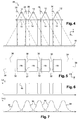
- fuzzy images are represented at figure 5 in dashed lines which symbolize the limit beyond which the fuzzy image illuminates substantially more, while the pixels 18 are represented in solid lines.
- the fuzzy transition image 30 thus has the shape of a rectangle which is delimited transversely by fuzzy edges 32 which fade, that is to say whose luminous illumination decreases, proportionally to the transverse distance of the center of the transition blurred image 30.
- the adjacent edges 32 opposite two adjacent fuzzy transition images are completely faded, i.e., the illuminance tends to zero, on a common pixel 18 arranged between the two dark intervals. 20 illuminated by said blurred images of transition 30, as illustrated in figure 5 and the graphs of Figures 6 and 7 .
- the blurred transition image 30 is projected so that its brightest central portion illuminates the dark interval associated with illumination at most equivalent to that of the pixels 18, for example about 100 lux.
- the blurred transition image 30 has a vertical height sufficient to fully illuminate the dark gap 20 thereby giving the impression that the road light beam illuminates the road homogeneously.
- This feature makes it possible to avoid the unpleasant impression given by the non-homogeneous grid-shaped illumination produced by the light beam emitted by the lighting device 10 produced according to the state of the art, in other words the light beam emitted by the lighting device 26 produced according to the invention illuminates homogeneously.
- the blurred transition image 30 fades transversely overlapping the adjacent pixels 18. As shown in FIGS. Figures 6 and 7 , the blurred transition image 30 fades completely before reaching the opposite edge 22 of the pixel 18 it overlaps. Thus, the blurred transition image 30 illuminates only a single dark interval 20.
- the illuminance of the blurred transition image 30 decreases to less than 1 lux at a distance from the opposite edge 22 of the pixel 18 it overlaps.
- the illuminance of the fuzzy transition image 30 becomes less than 1 lux transversely in the middle of each pixel 18 located on either side of the associated dark interval.
- Two adjacent fuzzy transition images overlap here on a common pixel 18 located between the two dark gaps illuminated by said two fuzzy transition images 30.
- the lighting device 26 furthermore comprises two complementary light sources 34 which are associated with projection means so as to form blurred end images 36 which illuminate transversely beyond each of the transverse ends of the pixel alignment 18 by overlapping the associated transverse end pixel 18 and fading transversely outwardly at the the associated transverse end pixel 18.
- the complementary light sources 34 are formed by light-emitting diodes similar to those used for the main and transition light sources 12 and 28.
- the projection means associated with the complementary light sources 34 are formed by the projection means 14 associated with the transition light sources 28. These are the lenses 14 associated with the two main transverse end light sources 12. Thus, the lighting device 26 has few optical elements and is inexpensive to manufacture.
- each main, transition or complementary light source is associated with an individual lens.
- the end light sources 34 are arranged in accordance with the same requirements as the transition light sources 28 to produce a blurred end image 36 having a desired transverse spread and blur.
- Each fuzzy end image 34 has transversely at its middle a luminous illumination substantially equal to that of the associated end pixel 18, for example 100 lux.
- the middle of the blurred end image 34 is located transversely in the extension of the associated end pixel 18 outwardly, as indicated in FIG. figure 7 by the two transverse end curves indicated by reference 36.
- Each blurred end image 36 is transversely bounded by an outer blurred vertical edge 38 and an inner blurred vertical edge 32.
- the inner edge 32 is superimposed on the associated transverse end pixel 18, while the outer edge 38 is arranged at the outer edge 36. outside the pixel alignment 18.
- the blurred end image 36 illuminates no dark interval 20, but extends the illumination of the light beam transversely outwards.
- the blurred end images 36 make it possible to confer on the light beam blurred outer end edges 38.
- the emitted light beam thus gradually fades transversely towards the side of the road instead of being abruptly interrupted by a sharp line.
- the light beam produced by the lighting device 26 has the same appearance as a light beam produced by a traditional high beam produced by a projector equipped with a reflector and an arc lamp or filament.
- the blurred end image 36 here has the same illuminance profile as the blurred transition images 30 with respect to a cross-sectional line, as indicated in FIG. figure 7 .
- the interfering pixel 18 when using the lighting device 26 made according to the teachings of the invention, when an opposing vehicle is detected as being illuminated by a single interfering pixel 18, the interfering pixel 18 is turned off and the transition images 30 or end 36 which overlap it are also extinguished. Thus, a dark hole is formed in the road light beam to avoid dazzling the driver of the opposing vehicle. This dark hole, when formed by the extinction of an inner pixel 18, is delimited transversely by the sharp edges 22 of the two pixels 18 which surround it.
- the two interfering pixels 18 are extinguished as well as the fuzzy transition image 30 corresponding to the dark interval 20 located between said interfering pixels 18. Darkness is then created in the road light beam.
- This dark hole is, however, delimited transversely by the two blurred images of transitions 30 or end 36 corresponding to the two dark intervals 20 which flank the two interfering pixels externally.
- the dark hole has a width smaller than that of the two interfering pixels 18, thus allowing the driver of the vehicle to see a large part of the illuminated road without dazzling the driver of the opposing vehicle.
- the road light beam is substantially homogeneous.
- FIG 8 a lighting device 40 made according to a second embodiment of the invention.
- This lighting device 40 is similar to the lighting device 10 produced according to the state of the art. It thus comprises a single common lens 14 for projecting the image of the main light sources 12.
- the lighting device 40 comprises four transition light sources 28 formed by light-emitting diodes, and two end light sources 34 also formed by light-emitting diodes.
- the projection means 42 associated with the transition light sources 28 are distinct from the projection means 14 associated with the main light sources 12.
- the projection means 42 associated with the transition light sources 28 will be qualified as “transition” in order to differentiate them from the projection means 14 associated with the main light sources 12 which will be said to be "main”.
- transition light sources 28 are shifted transversely relative to the alignment of main light sources 12. They are here divided into two groups which are arranged transversely on either side of the alignment of main light sources 12.
- all the transition light sources are arranged transversely on the same side of the alignment of main light sources.
- the transition projection means 42 are formed by two lenses 42 each of which is associated with a group of transition light sources 28.
- the fuzzy transition images 30 have the same positioning and illumination characteristics as the fuzzy transition images 30 produced by the lighting device 26 of the first embodiment, as shown in FIGS. Figures 5, 6 and 7 .
- the transition light sources 28 are arranged with respect to the transition lens 42 so as to obtain the desired characteristics.
- the lighting device 40 according to the second embodiment also comprises two complementary light sources 34 for forming blurred end images 36 as explained in the first embodiment.
- the projection means associated with the complementary light sources 34 are formed by the transition projection means 42.
- the complementary light sources 34 are thus arranged with respect to the transition lenses 42 so as to obtain blurred end images 36 presenting the same characteristics as in the first embodiment.
- This second embodiment thus makes it possible to adapt the invention to a lighting device 10 produced according to the state of the art by adding the complementary transition light sources 28 and the associated projection means 42.
- the lighting device 26 or 40 comprises at least two transition light sources 28 producing transversely aligned blurred transition images, each of which illuminates. at least one associated dark interval.
- the edges 32 opposite two adjacent fuzzy transition images fade completely into a common pixel 18.
- the lighting device comprises only two transition light sources each of which produces a fuzzy transition image 30, the pixel alignment 18 further comprising three dark intervals 20.
- the transition images 30 also form the fuzzy end images . Indeed, each transition image 30 is delimited transversely by an inner edge which is superimposed on a pixel 18 and an outer edge 38 which illuminates transversely on the outside in the extension of the pixel alignment 18.
- Each transition image 30 here illuminates an associated side of the road.
- each fuzzy transition image 30 is superimposed on a common pixel 18.
- each fuzzy transition image 30 is thus superimposed on at least one pixel in its entirety, in other words, each fuzzy transition image 30 fully encompasses at least one pixel 18.
- the fuzzy left transition image 30 fully illuminates two dark intervals as well as the lower left side of the road.
- the blurred images arranged transversely on the sides can illuminate several dark intervals, while in the axis of the road, that is to say say at the location with the highest probability of detecting enemy vehicles, one can opt for fuzzy transition images each associated with a single dark interval.
- the lighting device comprises a single transition light source whose transition image is superimposed on the entire pixel alignment and which fades transversely beyond the pixels. transverse end on either side of the pixel alignment.
- the fuzzy transition image must, however, be extinguished each time an opposing vehicle is detected, which does not ensure a generally homogeneous appearance of the light beam even when an opposing vehicle is detected as it is the case. in the previous embodiments and variants.
- the invention has been presented with a single alignment of four main light sources 12.
- the number of main light sources 12 may vary.
- the lighting device may have a matrix arrangement of sixteen light-emitting diodes arranged in two transverse rows of eight diodes each.
Abstract
L'invention concerne un dispositif d'éclairage (26, 40) pour véhicule automobile qui comporte : - une pluralité de sources lumineuses principales (12) sélectivement activables qui sont agencées selon un alignement transversal ; - des moyens optiques de projection (14) qui sont agencés de manière à projeter une image à l'infini de chaque source lumineuse principale (12), les images formant des pixels (18) présentant chacun au moins un bord net, les pixels (18) étant disjoints et alignés transversalement, deux pixels (18) adjacents étant séparés transversalement par un intervalle sombre (20). Selon l'invention, le dispositif comporte au moins une source lumineuse de transition (28) dont une image de transition (30) est projetée à l'infini par des moyens optiques de projection (14, 42) associés, chaque image de transition (30) éclairant entièrement au moins un intervalle sombre (20) en chevauchant les pixels (18) adjacents audit intervalle sombre (20), chaque source lumineuse de transition (28) étant susceptible d'être activée sélectivement.The invention relates to a lighting device (26, 40) for a motor vehicle comprising: a plurality of selectively activatable main light sources (12) which are arranged in a transverse alignment; - optical projection means (14) which are arranged to project an image at infinity of each main light source (12), the images forming pixels (18) each having at least one sharp edge, the pixels ( 18) being disjoint and transversely aligned, two adjacent pixels (18) being transversely separated by a dark gap (20). According to the invention, the device comprises at least one transition light source (28) of which a transition image (30) is projected at infinity by associated projection means (14, 42), each transition image ( 30) fully illuminating at least one dark interval (20) by overlapping the pixels (18) adjacent said dark gap (20), each transition light source (28) being selectively energizable.
Description
L'invention se rapporte à un dispositif d'éclairage pour véhicule automobile destiné à produire un faisceau lumineux adaptatif formant des pixels activables individuellement.The invention relates to a lighting device for a motor vehicle for producing an adaptive light beam forming individually activatable pixels.
L'invention se rapporte plus particulièrement à un dispositif d'éclairage adaptatif pour véhicule automobile qui comporte :
- une pluralité de sources lumineuses principales sélectivement activables qui sont agencées selon un alignement transversal, deux sources lumineuses principales adjacentes étant écartées transversalement ;
- des moyens optiques de projection qui sont agencés de manière à projeter une image à l'infini de chaque source lumineuse principale, les images formant des pixels présentant chacun au moins un bord net, les pixels étant disjoints et alignés transversalement, deux pixels adjacents étant séparés transversalement par un intervalle sombre ;
- a plurality of selectively activatable main light sources which are arranged in a transverse alignment, two adjacent main light sources being transversely spaced apart;
- projection optical means which are arranged to project an infinite image of each main light source, the images forming pixels each having at least one sharp edge, the pixels being disjoint and aligned transversely, two adjacent pixels being separated transversely by a dark interval;
Un tel dispositif d'éclairage est déjà connu pour éclairer la route avec une fonction dite « feu de route ». Un feu de route permet d'éclairer la route sur toute sa largeur ainsi que sur les bas côtés, sur une grande distance en avant du véhicule automobile.Such a lighting device is already known to illuminate the road with a so-called "high beam" function. A high beam illuminates the road along its entire width as well as on the low sides, a great distance ahead of the motor vehicle.
D'autres véhicules automobiles, appelés par la suite « véhicules adverses », sont susceptibles de rouler sur la même route que ledit véhicule comportant le dispositif d'éclairage à pixels. Les véhicules adverses roulent soit dans le même sens que le véhicule automobile, soit dans un sens inverse.Other motor vehicles, hereinafter called "opposing vehicles", are likely to roll on the same road as said vehicle having the pixel lighting device. The opposing vehicles roll either in the same direction as the motor vehicle, or in the opposite direction.
Par la suite lorsque le terme « véhicule automobile » est employé sans autres précisions, il s'agit du véhicule équipé du dispositif d'éclairage adaptatif selon l'invention.Subsequently, when the term "motor vehicle" is used without further specification, it is the vehicle equipped with the adaptive lighting device according to the invention.
Lorsque des véhicules adverses roulent sur cette route, le faisceau lumineux peut être commandé afin que les pixels dits « interférents », c'est-à-dire les pixels qui sont susceptibles d'éblouir les conducteurs des autres véhicules, soient éteints. Ainsi un trou d'obscurité est créé dans le faisceau lumineux afin de ne pas éblouir le conducteur d'un véhicule adverse.When opposing vehicles drive on this road, the light beam can be controlled so that the pixels known as "interfering", that is to say the pixels that are likely to dazzle the drivers of other vehicles, are extinguished. Thus a dark hole is created in the light beam so as not to dazzle the driver of an opposing vehicle.
Cependant, lorsque le véhicule adverse est situé à cheval sur plusieurs pixels voisins, lesdits pixels voisins doivent tous être éteints.However, when the opposing vehicle is straddling several neighboring pixels, said neighboring pixels must all be extinguished.
Lorsque le véhicule ne fait qu'effleurer un pixel voisin, ledit pixel voisin doit tout de même être éteint pour éviter tout risque d'éblouissement. Cependant, une grande partie de la route se retrouve alors dans l'obscurité.When the vehicle only touches a neighboring pixel, said neighboring pixel must still be turned off to avoid any risk of glare. However, much of the road ends up in darkness.
En outre, les pixels sont disjoints. Le conducteur du véhicule perçoit donc un éclairage non homogène divisé par une grille sombre. Or, les projecteurs classiques émettant des feux de route présentent un éclairage homogène qui s'estompe transversalement sur les côtés. Par projecteur classique, on comprendra par exemple un projecteur comportant une lampe à filament ou à arc et un réflecteur.In addition, the pixels are disjoint. The driver of the vehicle therefore perceives uneven illumination divided by a dark grid. However, conventional headlamps emitting high beam have a uniform illumination that fades transversely on the sides. By conventional projector, it will be understood for example a projector comprising a filament lamp or arc and a reflector.
Cette différence sensible entre un feu de route classique et un feu de route « à pixels » est susceptible de perturber le conducteur du véhicule automobile et, ainsi, de dégrader le confort de conduite du véhicule automobile.This significant difference between a conventional high beam and a high beam "pixel" is likely to disturb the driver of the motor vehicle and thus degrade the driving comfort of the motor vehicle.
Ainsi, notamment pour permettre un éclairage optimal pour un confort de conduite accru, l'invention propose un dispositif d'éclairage du type décrit précédemment, caractérisé en ce qu'il comporte au moins une source lumineuse de transition dont une image de transition est projetée à l'infini par des moyens optiques de projection associés, chaque image de transition éclairant entièrement au moins un intervalle sombre en chevauchant les pixels adjacents audit intervalle sombre, chaque source lumineuse de transition étant susceptible d'être activée sélectivement.Thus, in particular to allow optimal lighting for increased driving comfort, the invention proposes a lighting device of the type described above, characterized in that it comprises at least one transition light source of which a transition image is projected to infinity by associated projection optical means, each transition image fully illuminating at least one dark interval by overlapping the pixels adjacent to said dark interval, each transition light source being selectively activated.
Selon d'autres caractéristiques de l'invention :
- l'intervalle sombre présente une dimension transversale inférieure à la moitié de la dimension transversale de l'un des pixels adjacents à cet intervalle sombre ;
- l'intervalle sombre présente une dimension transversale inférieure au quart de la dimension transversale de l'un des pixels adjacents à cet intervalle sombre ;
- le dispositif d'éclairage comporte une unique source lumineuse de transition dont l'image de transition est superposée à la totalité des pixels de l'alignement en éclairant entièrement la totalité des intervalles sombres ;
- l'unique image de transition s'estompe transversalement au-delà des pixels d'extrémité transversale de part et d'autre de l'alignement de pixels ;
- le dispositif d'éclairage comporte au moins deux sources lumineuses de transition produisant des images de transition alignées transversalement dont chacune éclaire entièrement au moins un intervalle sombre associé, les bords adjacents de deux images de transition adjacentes s'estompent totalement dans un pixel commun ;
- le dispositif d'éclairage comporte au moins autant de sources lumineuses de transition que d'intervalles sombres de manière que l'image de transition de chaque source lumineuse de transition éclaire un intervalle sombre associé, les bords adjacents de deux images de transition adjacentes s'estompant totalement sur un pixel commun agencé entre les deux intervalles sombres associés auxdites deux images de transition adjacentes ;
- les images de transition d'extrémité transversale s'estompent transversalement au-delà du pixel d'extrémité transversal associé ;
- le dispositif d'éclairage comporte deux sources lumineuses complémentaires qui sont associées à des moyens de projection de manière à former des images d'extrémité qui éclairent chacune dans le prolongement d'une extrémité transversale de l'alignement de pixels en chevauchant le pixel d'extrémité transversal associé et en s'estompant transversalement vers l'extérieur ;
- les moyens de projection associés des sources lumineuses de transition sont formés par les moyens de projection associés aux sources lumineuses principales ;
- les moyens de projections associés aux sources lumineuses de transition sont au moins en partie distincts des moyens de projection associés aux sources lumineuses principales ;
- les moyens de projection associés aux sources lumineuses complémentaires sont formés par les moyens de projection associés aux sources lumineuses de transition ;
- les moyens de projection sont formés par au moins une lentille ;
- les moyens de projection sont formés par au moins un miroir ;
- les moyens de projection sont formés par un ensemble constitué d'au moins un miroir et une lentille
- une lentille individuelle est associée à chacune des sources lumineuses principales.
- un miroir individuel est associé à chacune des sources lumineuses principales.
- un ensemble individuel comportant au moins un miroir et une lentille est associé à chacune des sources lumineuses principales.
- l'image de transition et/ou l'image d'extrémité est floue.
- l'image de transition et/ou l'image d'extrémité est nette.
- the dark interval has a transverse dimension less than half the transverse dimension of one of the pixels adjacent to this dark interval;
- the dark interval has a transverse dimension less than a quarter of the transverse dimension of one of the pixels adjacent to this dark interval;
- the lighting device comprises a single transition light source whose transition image is superimposed on all the pixels of the alignment by illuminating the entire dark intervals;
- the single transition image fades transversely beyond the transverse end pixels on either side of the pixel alignment;
- the illumination device comprises at least two transition light sources producing transversely aligned transition images, each of which fully illuminates at least one associated dark interval, the adjacent edges of two adjacent transition images completely fade into a common pixel;
- the illumination device comprises at least as many transition light sources as dark intervals so that the transition image of each transition light source illuminates an associated dark interval, the adjacent edges of two adjacent transition images s' completely blending on a common pixel arranged between the two dark intervals associated with said two adjacent transition images;
- the transverse end transition images fade transversely beyond the associated transverse end pixel;
- the lighting device comprises two complementary light sources which are associated with projection means so as to form end images which each illuminate in the extension of a transverse end of the alignment of pixels by overlapping the pixel of associated transverse end and fading transversely outwards;
- the associated projection means of the transition light sources are formed by the projection means associated with the main light sources;
- the projection means associated with the transition light sources are at least partially distinct from the projection means associated with the main light sources;
- the projection means associated with the complementary light sources are formed by the projection means associated with the transition light sources;
- the projection means are formed by at least one lens;
- the projection means are formed by at least one mirror;
- the projection means are formed by an assembly consisting of at least one mirror and a lens
- an individual lens is associated with each of the main light sources.
- an individual mirror is associated with each of the main light sources.
- an individual assembly comprising at least one mirror and a lens is associated with each of the main light sources.
- the transition image and / or the end image is fuzzy.
- the transition image and / or the end image is clear.
D'autres caractéristiques et avantages apparaîtront au cours de la lecture de la description détaillée qui va suivre pour la compréhension de laquelle on se reportera aux dessins annexés parmi lesquels :
- la
figure 1 est une vue schématique de dessus qui représente un dispositif d'éclairage adaptatif à pixels réalisé selon l'état de la technique qui éclaire un écran ; - la
figure 2 est une vue de face qui représente l'image produite par le dispositif d'éclairage de lafigure 1 sur l'écran ; - la
figure 3 est un graphique qui représente l'éclairement lumineux de l'écran en lux en fonction de la position transversale sur l'écran le long d'une ligne transversale qui coupe les pixels ; - la
figure 4 est une vue similaire à celle de lafigure 1 qui représente un dispositif d'éclairage adaptatif réalisé selon les enseignements de l'invention qui comporte des sources lumineuses de transition et des sources lumineuses complémentaires ; - la
figure 5 est une vue similaire à celle de lafigure 2 qui représente l'image produite par le dispositif d'éclairage de lafigure 4 sur l'écran ; - la
figure 6 est un graphique similaire à celui de lafigure 3 qui représente l'éclairement lumineux, en lux, des pixels de lafigure 5 le long d'une ligne de coupe transversale ; - la
figure 7 est un graphique qui représentant l'éclairement lumineux, en lux, des images de transition et des images d'extrémité le long de la ligne transversale de coupe avec la même échelle et la même origine que le graphique de lafigure 6 ; - la
figure 8 est une vue similaire à celle de lafigure 4 qui représente le dispositif d'éclairage réalisé selon un deuxième mode de réalisation de l'invention ; - la
figure 9 est une vue similaire à celle de lafigure 5 qui représente l'image produite par un dispositif d'éclairage réalisé selon une variante de l'invention.
- the
figure 1 is a schematic view from above which shows an adaptive pixel lighting device made according to the state of the art which illuminates a screen; - the
figure 2 is a front view that represents the image produced by the lighting device of thefigure 1 on the screen ; - the
figure 3 is a graph that represents the illuminance of the screen in lux as a function of the transverse position on the screen along a transverse line that intersects the pixels; - the
figure 4 is a view similar to that of thefigure 1 which represents an adaptive lighting device made according to the teachings of the invention which comprises transition light sources and complementary light sources; - the
figure 5 is a view similar to that of thefigure 2 which represents the image produced by the lighting device of thefigure 4 on the screen ; - the
figure 6 is a graph similar to that of thefigure 3 which represents the illuminance, in lux, of the pixels of thefigure 5 along a line of cross section; - the
figure 7 is a graph that represents illuminance, in lux, of transition images and end images along the cross-sectional line with the same scale and origin as the graph of thefigure 6 ; - the
figure 8 is a view similar to that of thefigure 4 which represents the lighting device produced according to a second embodiment of the invention; - the
figure 9 is a view similar to that of thefigure 5 which represents the image produced by a lighting device produced according to a variant of the invention.
Dans la suite de la présente description :
- des éléments ayant des fonctions similaires, analogues ou identiques seront désignés par des mêmes numéros de référence,
- on adoptera à titre non limitatifs des orientations longitudinale dirigée d'arrière en avant, verticale dirigée de haut en bas et transversale qui sont indiquées par le trièdre « L,V,T » des Figures,
- on comprendra les termes « chevaucher » et « superposer » appliqués à deux images lumineuses comme étant l'éclairage d'une surface commune par les deux images,
- on qualifiera de « transversal » un alignement d'images s'étendant selon une direction contenue dans un plan normal à l'axe du véhicule, quelle que soit l'orientation de cet alignement dans ce plan, horizontale, verticale ou oblique, et
- on qualifiera d'« adjacents » des éléments voisins, qu'ils soient attenants, disjoints ou même qu'ils se recouvrent légèrement
- elements with similar, similar or identical functions will be designated by the same reference numbers,
- non-limiting directions of longitudinal direction directed from back to front, vertical directed from top to bottom and transverse which are indicated by the trihedron "L, V, T" of the Figures,
- the terms "overlap" and "superimpose" applied to two luminous images will be understood as being the illumination of a common surface by the two images,
- the term "transversal" shall be understood to mean an alignment of images extending in a direction contained in a plane normal to the axis of the vehicle, whatever the orientation of this alignment in this plane, horizontal, vertical or oblique, and
- adjoining elements, whether adjoining, disjointed or even slightly overlapping, will be termed adjacent
On a représenté à la
Le dispositif d'éclairage 10 est généralement enfermé dans un boîtier 11 fermé vers l'avant par une glace transparente.The
Le dispositif d'éclairage 10 comporte une pluralité de sources lumineuses principales 12 qui sont agencées selon un alignement transversal. Chaque source lumineuse principale est formée par une diode électroluminescente 12 qui présente une surface éclairante orientée vers l'avant.The
Le dispositif d'éclairage comporte ici quatre sources lumineuses principales 12 qui sont identiques entre elles. La surface éclairante présente une forme rectangulaire de grand côté vertical et de petit côté transversal.The lighting device here comprises four main
Les dimensions de la surface éclairante sont très réduites, par exemple de moins de 1 mm de côté.The dimensions of the illuminating surface are very small, for example less than 1 mm in size.
Chaque diode électroluminescente principale 12 est portée par une carte à circuit imprimé (non représentée) individuelle comportant des moyens électroniques de commande de l'activation de ladite diode électroluminescente principale 12. Chaque source lumineuse principale 12 est ainsi activable sélectivement et individuellement.Each main light-emitting
Une source lumineuse principale 12 activée produit de la lumière tandis qu'une source lumineuse principale 12 désactivée est éteinte.An activated main
En variante, les diodes électroluminescentes principales sont montées sur une carte à circuit imprimée commune (non représentée), chaque diode électroluminescente principale étant activable sélectivement et individuellement.Alternatively, the main light-emitting diodes are mounted on a common printed circuit board (not shown), each main light-emitting diode being selectively and individually activatable.
Les surfaces éclairantes de deux sources lumineuses principales 12 adjacentes sont écartées transversalement d'une distance « D1 » très faible par rapport aux dimensions de leur surface éclairante, par exemple de l'ordre de 0,1 mm, c'est-à-dire dix fois plus petite que la longueur d'un côté de la surface éclairante. A cet égard, on remarquera que les
Cette distance « D1 » est notamment prévue de manière que chaque source lumineuse principale 12 puisse être activée indépendamment des autres, en évitant que l'activation d'une des sources lumineuses principales 12 ne provoque l'activation involontaire des sources lumineuses principales 12 adjacentes par effet de champ.This distance "D1" is in particular provided so that each main
Le dispositif d'éclairage 10 comporte aussi des moyens optiques de projection 14 qui sont agencés longitudinalement en avant des sources lumineuses. Les moyens de projection sont ici formés par une lentille principale 14 commune à toutes les sources lumineuses principales 12.The
La lentille 14 est agencée longitudinalement en avant des sources lumineuses principales 12. La lentille 14 est agencée et conformée de manière à projeter, selon l'axe optique, une image nette à l'infini de chaque source lumineuse principale 12. Chaque source lumineuse principale 12 est plus particulièrement agencée dans le plan focal de la lentille 14 associée.The
Chaque source lumineuse principale 12 participe ainsi à former une partie du faisceau lumineux de route.Each main
Dans la pratique, l'image à l'infini est contrôlée, selon les normes européennes, par projection sur un écran 16 vertical transversal agencé longitudinalement en avant à une distance de 25 m du dispositif de projection 10.In practice, the image at infinity is controlled, according to European standards, by projection on a vertical
On a représenté à la
Chaque pixel 18 présente une forme rectangulaire qui est l'image de la forme de la surface éclairante de la source lumineuse principale 12 associée. Un pixel proche de l'axe optique de la lentille présente par exemple une dimension de l'ordre de la dizaine de centimètres de côté.Each
Les pixels 18 sont ici tous identiques en formes et en dimensions.The
En variante non représentée de l'invention, les pixels 18 peuvent présenter des formes et des dimensions différentes en fonction de leur position transversale par rapport à l'axe de la route. Les pixels proches de l'axe de la route présentent par exemple des dimensions transversales inférieures à celles des pixels excentrés de manière que la densité de pixels soit plus grande dans l'axe que sur les côtés.In a variant not shown of the invention, the
Les pixels 18 sont disjoints les uns des autres et ils sont alignés transversalement. Ainsi, le faisceau lumineux de route est formé par la juxtaposition de faisceaux lumineux élémentaires dont chacun est formé par une source lumineuse principale 12 associée.The
Deux pixels adjacents 18 sont séparés transversalement par un intervalle sombre 20. Chaque pixel 18 est délimité transversalement par deux bords 22 nets. Ainsi, les intervalles sombres 20 sont délimités transversalement très nettement par les bords 22 en vis-à-vis des deux pixels 18 qui l'encadrent.Two
Chaque intervalle sombre 20 présente par exemple une dimension transversale « D2 » de l'ordre du centimètre, et pouvant même être égale à 0,25 cm dans certains cas. Chaque intervalle sombre 20 est en fait l'image de l'écartement « D1 » entre la surface éclairante de deux sources lumineuses principales 12 adjacentes. Généralement, l'intervalle sombre 20 présente une dimension transversale D2 inférieure à la moitié de la dimension transversale de l'un des pixels adjacents 18 à cet intervalle sombre. Préférentiellement, cet intervalle sombre 20 présente une dimension transversale D2 inférieure au quart de la dimension transversale de l'un des pixels adjacents 18 à cet intervalle sombre.Each
En outre, les pixels 18 d'extrémité transversale sont délimités transversalement vers l'extérieur de l'alignement par un bord extérieur 24 qui est lui aussi très net.In addition, the
Par le terme « net », on comprendra qu'un observateur situé à une distance de 25 m de l'écran 16 ne discerne pas de flou et qu'il perçoit les bords 22, 24 comme des lignes claires.By the term "net", it will be understood that an observer located at a distance of 25 m from the
On comprendra que le terme « extérieur » est employé pour définir une orientation transversalement tournée dans un sens opposé à l'alignement de pixels 18 en partant d'un des pixels 18 d'extrémité.It will be understood that the term "exterior" is used to define an orientation transversely rotated in a direction opposite to the
Selon les normes en vigueur, les sources lumineuses principales 12 sont par exemple choisies de manière que chaque pixel 18 délivre un éclairement lumineux compris en 50 et 100 lux, tandis que chaque intervalle sombre 20 présente un éclairement lumineux inférieur à 1 lux. Dans l'exemple représenté à la
Sur la
L'activation et la désactivation des sources lumineuses principales 12 est commandée par un système (non représenté) de détection de véhicules adverses qui est embarqué à bord du véhicule. De tels systèmes de détection sont bien connus et ne seront pas détaillés par la suite. Il s'agit par exemple d'un système de détection qui comporte des moyens de prise d'image de la route et des moyens de traitement de ladite image.The activation and deactivation of the main
Lors de l'utilisation du dispositif d'éclairage 10, toutes les sources lumineuses principales 12 sont activées de manière à allumer la totalité des pixels 18 pour éclairer la route sur toute sa largeur.When using the
Lorsqu'un véhicule adverse est détecté comme étant éclairé par un pixel 18 dit « interférent », le système de détection commande la désactivation de la source lumineuse principale 12 associée au pixel 18 interférent. Le pixel interférent 18 est ainsi éteint de manière à ne pas éblouir le conducteur du véhicule adverse. Un trou d'obscurité est ainsi créé dans le faisceau lumineux de route de manière que la zone de la route comportant le véhicule adverse soit laissée dans l'obscurité tandis que le reste de la route est éclairé par les autres pixels 18 qui sont restés allumés.When an opposing vehicle is detected as being illuminated by an "interfering"
Lorsqu'un véhicule adverse est détecté comme étant compris dans un intervalle sombre 20, le système considère que le véhicule adverse chevauche deux pixels adjacents 18. Les deux pixels 18 interférents sont alors éteints.When an opposing vehicle is detected as being in a
On a constaté que le fait d'éteindre deux pixels adjacents 18 provoquait un trou d'obscurité très large privant d'éclairage une grande partie de la route alors que le véhicule adverse est susceptible de n'occuper qu'une tranche transversale de faible épaisseur du trou d'obscurité.It has been found that extinguishing two
De plus, l'éclairage en pixels 18 disjoints en forme de grille n'est pas homogène.In addition, the lighting in grated
Pour résoudre ces problème, l'invention propose un dispositif d'éclairage 26 adaptatif qui présente la plupart des caractéristiques décrites pour le dispositif d'éclairage 10 réalisé selon l'état de la technique. Pour simplifier la compréhension de l'invention, seules les caractéristiques différentes du dispositif d'éclairage 10 selon l'état de la technique seront détaillées par la suite.To solve these problems, the invention proposes an
Dans ce premier mode de réalisation de l'invention représenté aux
Le dispositif d'éclairage 26 comporte au moins une source lumineuse de transition 28 qui est associée des moyens optiques de projection pour projeter à l'infini une image 30 de transition entre deux pixels 18.The
Chaque image de transition 30 est projetée de manière à éclairer entièrement au moins un intervalle sombre 20 en chevauchant les pixels adjacents 18 audit intervalle sombre 20.Each
En outre, chaque source lumineuse de transition 28 est susceptible d'être activée sélectivement et individuellement.In addition, each
Dans le premier mode de réalisation représenté à la
Le nombre d'intervalles sombres 20 est égal au nombre de sources lumineuses principales 12 diminué d'une unité. Le dispositif d'éclairage 26 comporte donc trois sources lumineuses de transition 28 qui sont susceptibles de produire trois images de transition 30 dont chacune éclaire un intervalle sombre 20 associé.The number of
Les sources lumineuses de transition 28 sont chacune formées par une diode électroluminescente de transition 28 qui est similaire à une diode électroluminescente principale 12. Ainsi, chaque source lumineuse de transition 28 présente une surface éclairante de forme rectangulaire de grand côté vertical.The
Les moyens de projection associés aux sources lumineuses de transition 28 sont avantageusement formés par les moyens de projection 14 associés aux sources lumineuses principales 12. Ainsi, chaque source lumineuse de transition 28 est agencée longitudinalement en arrière d'une lentille 14 associée du dispositif d'éclairage 26. Ainsi, le dispositif d'éclairage 26 comporte peu d'éléments optiques et il est peu onéreux à fabriquer.The projection means associated with the
Lorsque l'on désire que les images de transition 30 soient floues, pour obtenir le flou désiré ainsi que le positionnement désiré de l'image floue de transition 30 entre deux pixels 18, la source lumineuse de transition 28 est excentrée par rapport à l'axe optique de la lentille 14 associée.When it is desired that the transition images be blurred, to obtain the desired blur as well as the desired positioning of the blurred transition image between two
Outre la position excentrée de la source lumineuse de transition 28, il est aussi possible de jouer sur le positionnement longitudinal de la source lumineuse par rapport à la lentille 14 pour accentuer ou diminuer le flou de l'image floue de transition 30.In addition to the eccentric position of the
Pour plus de clarté, les images floues sont représentées à la
L'image floue de transition 30 présente ainsi la forme d'un rectangle qui est délimité transversalement par des bords flous 32 qui s'estompent, c'est-à-dire dont l'éclairement lumineux diminue, proportionnellement à l'éloignement transversal du centre de l'image floue de transition 30.The
Les bords adjacents 32 en vis-à-vis de deux images floues de transition 30 adjacentes s'estompent totalement, c'est-à-dire que l'éclairement lumineux tend vers zéro, sur un pixel 18 commun agencé entre les deux intervalles sombres 20 éclairés par lesdites images floues de transition 30, comme cela est illustré à la
Les graphiques des
L'image floue de transition 30 est projetée de manière que sa partie centrale la plus lumineuse éclaire l'intervalle sombre 20 associé avec un éclairement lumineux au plus équivalent à celui des pixels 18, par exemple d'environ 100 lux. L'image floue de transition 30 présente une hauteur verticale suffisante pour éclairer entièrement l'intervalle sombre 20 en donnant ainsi l'impression que le faisceau lumineux de route éclaire la route de façon homogène.The
Cette caractéristique permet d'éviter l'impression désagréable donnée par l'éclairage non homogène en forme de grille produit par le faisceau lumineux émis par le dispositif d'éclairage 10 réalisé selon l'état de la technique, en d'autres termes, le faisceau lumineux émis par le dispositif d'éclairage 26 réalisé selon l'invention éclaire de façon homogène.This feature makes it possible to avoid the unpleasant impression given by the non-homogeneous grid-shaped illumination produced by the light beam emitted by the
L'image floue de transition 30 s'estompe transversalement en chevauchant les pixels adjacents 18. Comme représenté aux
Comme représenté à la
Deux images floues de transition 30 adjacentes se chevauchent ici sur un pixel 18 commun situé entre les deux intervalles sombres 20 éclairés par lesdites deux images floues de transition 30.Two adjacent fuzzy transition images overlap here on a
Le dispositif d'éclairage 26 comporte en outre deux sources lumineuses complémentaires 34 qui sont associées à des moyens de projection de manière à former des images floues d'extrémité 36 qui éclairent transversalement au-delà de chacune des extrémités transversales de l'alignement de pixels 18 en chevauchant le pixel 18 d'extrémité transversal associé et en s'estompant transversalement vers l'extérieur au-delà du pixel 18 d'extrémité transversal associé.The
Les sources lumineuses complémentaires 34 sont formées par des diodes électroluminescentes similaires à celles employées pour les sources lumineuses principales 12 et de transition 28.The complementary
Les moyens de projection associés aux sources lumineuses complémentaires 34 sont formés par les moyens de projection 14 associés aux sources lumineuses de transition 28. Il s'agit ici des lentilles 14 associées au deux sources lumineuses principales 12 d'extrémité transversale. Ainsi, le dispositif d'éclairage 26 comporte peu d'éléments optiques et il est peu onéreux à fabriquer.The projection means associated with the complementary
Selon une variante non représentée de l'invention, chaque source lumineuse principale, de transition ou complémentaire est associée à une lentille individuelle.According to a not shown variant of the invention, each main, transition or complementary light source is associated with an individual lens.
Les sources lumineuses d'extrémité 34 sont agencées selon les mêmes prescriptions que les sources lumineuses de transition 28 afin de produire une image floue d'extrémité 36 présentant un étalement transversal et un flou désiré.The
Chaque image floue d'extrémité 34 présente transversalement en son milieu un éclairement lumineux sensiblement égal à celui du pixel 18 d'extrémité associé, par exemple 100 lux. Le milieu de l'image floue d'extrémité 34 est situé transversalement dans le prolongement du pixel d'extrémité associé 18 vers l'extérieur, comme cela est indiqué à la
Chaque image floue d'extrémité 36 est délimité transversalement par un bord vertical flou extérieur 38 et un bords vertical flou intérieur 32. Le bord intérieur 32 est superposé au pixel 18 d'extrémité transversale associé, tandis que le bord extérieur 38 est agencé à l'extérieur de l'alignement de pixels 18.Each
Ainsi, l'image floue d'extrémité 36 n'éclaire aucun intervalle sombre 20, mais prolonge l'éclairage du faisceau lumineux transversalement vers l'extérieur.Thus, the
Ces images floues d'extrémité 36 permettent de conférer au faisceau lumineux des bords d'extrémité extérieur 38 flous. Le faisceau lumineux émis s'estompe ainsi progressivement transversalement vers les bas-côtés de la route au lieu d'être interrompu brutalement par une ligne nette. Ainsi le faisceau lumineux produit par le dispositif d'éclairage 26 présente le même aspect qu'un faisceau lumineux produit par un feu de route traditionnel produit par un projecteur équipé d'un réflecteur et d'une lampe à arc ou à filament.These
L'image floue d'extrémité 36 présente ici le même profil d'éclairement lumineux que les images floues de transition 30 par rapport à une ligne de coupe transversale, comme indiqué à la
Ainsi, lors de l'utilisation du dispositif d'éclairage 26 réalisé selon les enseignements de l'invention, lorsqu'un véhicule adverse est détecté comme étant éclairé par un unique pixel 18 interférent, le pixel interférent 18 est éteint et les images de transition 30 ou d'extrémité 36 qui le chevauchent sont aussi éteintes. Ainsi, un trou d'obscurité est ménagé dans le faisceau lumineux de route pour éviter d'éblouir le conducteur du véhicule adverse. Ce trou d'obscurité, lorsqu'il est formé par l'extinction d'un pixel 18 intérieur, est délimité transversalement par les bords nets 22 des deux pixels 18 qui l'encadrent.Thus, when using the
Lorsque le véhicule adverse est détecté comme étant à cheval sur deux pixels 18 adjacents, les deux pixels interférents 18 sont éteints ainsi que l'image floue de transition 30 correspondant à l'intervalle sombre 20 situé entre lesdits pixels interférents 18. Un trou d'obscurité est alors créé dans le faisceau lumineux de route.When the opposing vehicle is detected as being straddling two
Ce trou d'obscurité est cependant délimité transversalement par les deux images floues de transitions 30 ou d'extrémité 36 correspondant aux deux intervalles sombres 20 qui flanquent extérieurement les deux pixels interférents. Ainsi, contrairement au dispositif d'éclairage 10 réalisé selon l'état de la technique, le trou d'obscurité présente une largeur inférieure à celle des deux pixels interférents 18, permettant ainsi au conducteur du véhicule de voir une grande partie de la route éclairée sans pour autant éblouir le conducteur du véhicule adverse.This dark hole is, however, delimited transversely by the two blurred images of
De plus, grâce aux images floues de transition et d'extrémité, le faisceau lumineux de route est sensiblement homogène.Moreover, thanks to the fuzzy transition and end images, the road light beam is substantially homogeneous.
On a représenté à la
Comme dans le premier mode de réalisation, le dispositif d'éclairage 40 comporte quatre sources lumineuses de transition 28 formées par des diodes électroluminescentes, et deux sources lumineuses d'extrémité 34 aussi formées par des diodes électroluminescentes.As in the first embodiment, the
Cependant, à la différence du dispositif d'éclairage 26 réalisé selon le premier mode de réalisation de l'invention, les moyens de projections 42 associés aux sources lumineuses de transition 28 sont distincts des moyens de projection 14 associés aux sources lumineuses principales 12.However, unlike the
Les moyens de projections 42 associés aux sources lumineuses de transition 28 seront qualifiés « de transition » afin de les différencier des moyens de projections 14 associés aux sources lumineuses principales 12 qui seront dits « principaux ».The projection means 42 associated with the
Ainsi, les sources lumineuses de transition 28 sont décalées transversalement par rapport à l'alignement de sources lumineuses principales 12. Elles sont ici divisées en deux groupes qui sont agencés transversalement de part et d'autre de l'alignement de sources lumineuses principales 12.Thus, the
Selon une variante non représentée de l'invention, toutes les sources lumineuses de transition sont agencées transversalement d'un même côté de l'alignement de sources lumineuses principales.According to a not shown variant of the invention, all the transition light sources are arranged transversely on the same side of the alignment of main light sources.
Les moyens de projection de transition 42 sont formés par deux lentilles 42 dont chacune est associée à un groupe de sources lumineuses de transition 28.The transition projection means 42 are formed by two
Les images floues de transition 30 présentent les mêmes caractéristiques de positionnement et d'éclairement lumineux que les images floues de transition 30 produite par le dispositif d'éclairage 26 du premier mode de réalisation, comme représenté aux
Le dispositif d'éclairage 40 selon le deuxième mode de réalisation comporte aussi deux sources lumineuses complémentaires 34 pour former des images floues d'extrémité 36 comme cela est expliqué dans le premier mode de réalisation.The
Avantageusement, les moyens de projection associés aux sources lumineuses complémentaires 34 sont formés par les moyens de projection de transition 42. Les sources lumineuses complémentaires 34 sont ainsi agencées par rapport aux lentilles de transition 42 de manière à obtenir des images floues d'extrémité 36 présentant les mêmes caractéristiques que dans le premier mode de réalisation.Advantageously, the projection means associated with the complementary
Ce deuxième mode de réalisation permet ainsi d'adapter l'invention à un dispositif d'éclairage 10 réalisé selon l'état de la technique en ajoutant les sources lumineuses de transition 28 et complémentaire et les moyens de projection 42 associés.This second embodiment thus makes it possible to adapt the invention to a
Dans une variante applicable aux dispositif d'éclairage 26 et 40 des premier et deuxième modes de réalisation, le dispositif d'éclairage 26 ou 40, comporte au moins deux sources lumineuses de transition 28 produisant des images floues de transition 30 alignées transversalement dont chacune éclaire au moins un intervalle sombre 20 associé. Les bords 32 en vis-à-vis de deux images floues de transition 30 adjacentes s'estompent totalement dans un pixel 18 commun.In a variant applicable to the
Dans l'exemple représenté à la
Les bords intérieurs 32 de chaque image floue de transition 30 sont superposés à un pixel 18 commun.The
Chaque image floue de transition 30 est ainsi superposée à au moins un pixel dans sa totalité, en d'autres termes, chaque image floue de transition 30 englobe entièrement au moins un pixel 18. Ainsi, comme représenté à la
Il s'agit bien entendu d'un exemple, et toutes les combinaisons sont possibles, par exemple les images floues agencés transversalement sur les côtés peuvent éclairer plusieurs intervalles sombres, tandis que dans l'axe de la route, c'est-à-dire à l'endroit présentant la plus grande probabilité de détection de véhicules adverses, on peut opter pour des images floues de transition chacune associée à un unique intervalle sombre.This is of course an example, and all combinations are possible, for example the blurred images arranged transversely on the sides can illuminate several dark intervals, while in the axis of the road, that is to say say at the location with the highest probability of detecting enemy vehicles, one can opt for fuzzy transition images each associated with a single dark interval.
Selon une variante non représentée de l'invention, le dispositif d'éclairage comporte une unique source lumineuse de transition dont l'image de transition est superposée à la totalité de l'alignement de pixels et qui s'estompe transversalement au-delà des pixels d'extrémité transversale de part et d'autre de l'alignement de pixels. On obtient ainsi un faisceau lumineux de route homogène. L'image floue de transition doit cependant être éteinte à chaque fois qu'un véhicule adverse est détecté, ce qui ne permet pas d'assurer un aspect globalement homogène du faisceau lumineux même lorsqu'un véhicule adverse est détecté comme c'est le cas dans les précédents modes de réalisation et variantes.According to a not shown variant of the invention, the lighting device comprises a single transition light source whose transition image is superimposed on the entire pixel alignment and which fades transversely beyond the pixels. transverse end on either side of the pixel alignment. This produces a homogeneous road light beam. The fuzzy transition image must, however, be extinguished each time an opposing vehicle is detected, which does not ensure a generally homogeneous appearance of the light beam even when an opposing vehicle is detected as it is the case. in the previous embodiments and variants.
L'invention a été présentée avec un seul alignement de quatre sources lumineuses principales 12. On comprendra cependant que le nombre de sources lumineuses principales 12 peut varier. Par exemple le dispositif d'éclairage peut présenter un agencement matriciel de seize diodes électroluminescentes agencées en deux rangées transversales de huit diodes chacune.The invention has been presented with a single alignment of four main
De même, bien que l'invention ait été décrite plus particulièrement avec des images de transition 30 floues et des images d'extrémité 36 floues, l'homme du métier pourra mettre en oeuvre l'invention en utilisant des images de transition 30 nettes et/ou des images d'extrémité 36 nettes, sans sortir du cadre de la présente invention.Also, although the invention has been more particularly described with fuzzy transition images and blurred end images, those skilled in the art will be able to practice the invention using sharp and sharp transition images. / or
Claims (15)
Applications Claiming Priority (2)
| Application Number | Priority Date | Filing Date | Title |
|---|---|---|---|
| FR0805356A FR2936585B1 (en) | 2008-09-29 | 2008-09-29 | ADAPTIVE LIGHTING DEVICE FOR MOTOR VEHICLE |
| EP09171453.5A EP2169295B1 (en) | 2008-09-29 | 2009-09-28 | Adaptive lighting device for motor vehicle |
Related Parent Applications (2)
| Application Number | Title | Priority Date | Filing Date |
|---|---|---|---|
| EP09171453.5A Division EP2169295B1 (en) | 2008-09-29 | 2009-09-28 | Adaptive lighting device for motor vehicle |
| EP09171453.5A Division-Into EP2169295B1 (en) | 2008-09-29 | 2009-09-28 | Adaptive lighting device for motor vehicle |
Publications (2)
| Publication Number | Publication Date |
|---|---|
| EP3130841A1 true EP3130841A1 (en) | 2017-02-15 |
| EP3130841B1 EP3130841B1 (en) | 2018-11-07 |
Family
ID=40474958
Family Applications (2)
| Application Number | Title | Priority Date | Filing Date |
|---|---|---|---|
| EP09171453.5A Active EP2169295B1 (en) | 2008-09-29 | 2009-09-28 | Adaptive lighting device for motor vehicle |
| EP16181263.1A Active EP3130841B1 (en) | 2008-09-29 | 2009-09-28 | Adaptive lighting device for a motor vehicle |
Family Applications Before (1)
| Application Number | Title | Priority Date | Filing Date |
|---|---|---|---|
| EP09171453.5A Active EP2169295B1 (en) | 2008-09-29 | 2009-09-28 | Adaptive lighting device for motor vehicle |
Country Status (4)
| Country | Link |
|---|---|
| EP (2) | EP2169295B1 (en) |
| JP (1) | JP5529479B2 (en) |
| FR (1) | FR2936585B1 (en) |
| PL (1) | PL2169295T3 (en) |
Families Citing this family (8)
| Publication number | Priority date | Publication date | Assignee | Title |
|---|---|---|---|---|
| FR2948439B1 (en) * | 2009-07-21 | 2011-08-05 | Valeo Vision | LIGHTING MODULE FOR A MOTOR VEHICLE PROJECTOR, AND PROJECTOR EQUIPPED WITH AT LEAST ONE SUCH MODULE. |
| JP2013012411A (en) * | 2011-06-29 | 2013-01-17 | Sharp Corp | Floodlight projector, and vehicular headlight |
| JP5758724B2 (en) * | 2011-07-07 | 2015-08-05 | 株式会社小糸製作所 | Vehicle headlamp |
| JP6075969B2 (en) * | 2012-05-22 | 2017-02-08 | 株式会社小糸製作所 | Vehicle headlamp |
| FR2991251B1 (en) * | 2012-06-04 | 2016-01-29 | Valeo Vision | ILLUMINATED LIGHT-SOURCE LIGHTING MODULE FOR IMPLEMENTING AN ADB FUNCTION |
| DE102012211613A1 (en) * | 2012-07-04 | 2014-01-09 | Automotive Lighting Reutlingen Gmbh | light module |
| KR101979572B1 (en) * | 2015-12-24 | 2019-05-17 | 에스엘 주식회사 | Automotive lamp |
| FR3072445B1 (en) * | 2017-10-16 | 2020-11-13 | Valeo Vision | LIGHT MODULE FOR MOTOR VEHICLES |
Citations (4)
| Publication number | Priority date | Publication date | Assignee | Title |
|---|---|---|---|---|
| FR2811621A1 (en) * | 2000-07-11 | 2002-01-18 | Koito Mfg Co Ltd | Cornering lamp for irradiating a road surface ahead of and in an oblique direction of a motor vehicle while the vehicle is moving around a curve, has multiple bulbs each with reflector at selected angle for wide viewing area |
| DE102006052749A1 (en) * | 2005-11-08 | 2007-05-10 | Koito Mfg. Co., Ltd. | Vehicle lighting system |
| JP2008037240A (en) * | 2006-08-04 | 2008-02-21 | Toyota Motor Corp | Headlamp for vehicle |
| EP2037167A2 (en) * | 2007-09-13 | 2009-03-18 | Koito Manufacturing Co., Ltd. | Lamp unit for vehicle headlamp and vehicle headlamp |
Family Cites Families (2)
| Publication number | Priority date | Publication date | Assignee | Title |
|---|---|---|---|---|
| JP4535965B2 (en) * | 2005-08-16 | 2010-09-01 | 株式会社小糸製作所 | Vehicle lighting |
| JP4730284B2 (en) * | 2006-11-07 | 2011-07-20 | トヨタ自動車株式会社 | Vehicle lighting device |
-
2008
- 2008-09-29 FR FR0805356A patent/FR2936585B1/en not_active Expired - Fee Related
-
2009
- 2009-09-28 PL PL09171453T patent/PL2169295T3/en unknown
- 2009-09-28 EP EP09171453.5A patent/EP2169295B1/en active Active
- 2009-09-28 EP EP16181263.1A patent/EP3130841B1/en active Active
- 2009-09-29 JP JP2009223756A patent/JP5529479B2/en active Active
Patent Citations (4)
| Publication number | Priority date | Publication date | Assignee | Title |
|---|---|---|---|---|
| FR2811621A1 (en) * | 2000-07-11 | 2002-01-18 | Koito Mfg Co Ltd | Cornering lamp for irradiating a road surface ahead of and in an oblique direction of a motor vehicle while the vehicle is moving around a curve, has multiple bulbs each with reflector at selected angle for wide viewing area |
| DE102006052749A1 (en) * | 2005-11-08 | 2007-05-10 | Koito Mfg. Co., Ltd. | Vehicle lighting system |
| JP2008037240A (en) * | 2006-08-04 | 2008-02-21 | Toyota Motor Corp | Headlamp for vehicle |
| EP2037167A2 (en) * | 2007-09-13 | 2009-03-18 | Koito Manufacturing Co., Ltd. | Lamp unit for vehicle headlamp and vehicle headlamp |
Also Published As
| Publication number | Publication date |
|---|---|
| PL2169295T3 (en) | 2017-04-28 |
| EP3130841B1 (en) | 2018-11-07 |
| JP5529479B2 (en) | 2014-06-25 |
| JP2010086961A (en) | 2010-04-15 |
| EP2169295A1 (en) | 2010-03-31 |
| EP2169295B1 (en) | 2016-09-14 |
| FR2936585A1 (en) | 2010-04-02 |
| FR2936585B1 (en) | 2016-05-27 |
Similar Documents
| Publication | Publication Date | Title |
|---|---|---|
| EP2169295B1 (en) | Adaptive lighting device for motor vehicle | |
| EP3301347B1 (en) | Lighting device for a motor vehicle comprising a light guide | |
| EP3517827B1 (en) | Light module comprising a primary optical element provided with two shaping layers | |
| EP3147557A1 (en) | Primary optical element for lighting module of a vehicle | |
| FR2934669A1 (en) | LIGHTING SYSTEM FOR A MOTOR VEHICLE | |
| FR3033621A1 (en) | LIGHT DEVICE WITH OPTICAL GUIDES | |
| FR3055979A1 (en) | CHARACTERISTICS OF PIXELISE LIGHT BEAM | |
| EP3266652B1 (en) | Lighting module generating a network of light beams | |
| EP3428513A1 (en) | Lighting device projecting two matrices of vertically-shifted light pixels | |
| WO2014191530A1 (en) | Lighting module for motor vehicle headlight, headlight equipped with such modules, and headlight assembly | |
| FR3056699A1 (en) | LUMINOUS MODULE AND LUMINOUS DEVICE FOR SELF-MOVING VEHICLE COMPRISING SUCH A LIGHT MODULE | |
| EP3201519B1 (en) | Lighting system with optimised intensity profile for motor vehicle headlight | |
| WO2021018657A1 (en) | Method for controlling a lighting device suitable for emitting two pixelated light beams with different resolutions | |
| FR3077540A1 (en) | VEHICLE COMPRISING A SOIL LIGHTING DEVICE | |
| EP3124853A1 (en) | Lighting and/or signalling device for a vehicle | |
| EP1947380B1 (en) | Multi-functional optical module for an automobile | |
| EP2472176A2 (en) | Lighting and/or signalling device, in particular of an automobile | |
| FR3035973A1 (en) | DEVICE FOR PROJECTING LUMINOUS INDICATIONS | |
| FR2727742A1 (en) | Signal lamp e.g. supplementary stop lamp for motor vehicle | |
| EP2169297B1 (en) | Optical module comprising an optical deviation element | |
| FR3039625A1 (en) | LIGHTING DEVICE FOR MOTOR VEHICLE | |
| EP3141805B1 (en) | Lighting system, in particular for a motor vehicle | |
| FR3082918A1 (en) | < P > LIGHT MODULE OF A MOTOR VEHICLE PRODUCING A PIXEL CROSSING BEAM < / P > | |
| FR3074562A1 (en) | LIGHTING DEVICE EMITTING A SEGMENT LUMINOUS BEAM | |
| WO2023274988A1 (en) | Pixelated lighting device employing direct reflection |
Legal Events
| Date | Code | Title | Description |
|---|---|---|---|
| PUAI | Public reference made under article 153(3) epc to a published international application that has entered the european phase |
Free format text: ORIGINAL CODE: 0009012 |
|
| STAA | Information on the status of an ep patent application or granted ep patent |
Free format text: STATUS: THE APPLICATION HAS BEEN PUBLISHED |
|
| AC | Divisional application: reference to earlier application |
Ref document number: 2169295 Country of ref document: EP Kind code of ref document: P |
|
| AK | Designated contracting states |
Kind code of ref document: A1 Designated state(s): AT BE BG CH CY CZ DE DK EE ES FI FR GB GR HR HU IE IS IT LI LT LU LV MC MK MT NL NO PL PT RO SE SI SK SM TR |
|
| STAA | Information on the status of an ep patent application or granted ep patent |
Free format text: STATUS: REQUEST FOR EXAMINATION WAS MADE |
|
| 17P | Request for examination filed |
Effective date: 20170727 |
|
| RBV | Designated contracting states (corrected) |
Designated state(s): AT BE BG CH CY CZ DE DK EE ES FI FR GB GR HR HU IE IS IT LI LT LU LV MC MK MT NL NO PL PT RO SE SI SK SM TR |
|
| REG | Reference to a national code |
Ref country code: DE Ref legal event code: R079 Ref document number: 602009055582 Country of ref document: DE Free format text: PREVIOUS MAIN CLASS: F21S0008100000 Ipc: F21S0041000000 |
|
| RIC1 | Information provided on ipc code assigned before grant |
Ipc: F21Y 115/10 20160101ALN20180409BHEP Ipc: F21S 41/00 20180101AFI20180409BHEP |
|
| GRAP | Despatch of communication of intention to grant a patent |
Free format text: ORIGINAL CODE: EPIDOSNIGR1 |
|
| STAA | Information on the status of an ep patent application or granted ep patent |
Free format text: STATUS: GRANT OF PATENT IS INTENDED |
|
| RIC1 | Information provided on ipc code assigned before grant |
Ipc: F21S 41/00 20180101AFI20180425BHEP Ipc: F21Y 115/10 20160101ALN20180425BHEP |
|
| INTG | Intention to grant announced |
Effective date: 20180528 |
|
| GRAS | Grant fee paid |
Free format text: ORIGINAL CODE: EPIDOSNIGR3 |
|
| GRAA | (expected) grant |
Free format text: ORIGINAL CODE: 0009210 |
|
| STAA | Information on the status of an ep patent application or granted ep patent |
Free format text: STATUS: THE PATENT HAS BEEN GRANTED |
|
| AC | Divisional application: reference to earlier application |
Ref document number: 2169295 Country of ref document: EP Kind code of ref document: P |
|
| AK | Designated contracting states |
Kind code of ref document: B1 Designated state(s): AT BE BG CH CY CZ DE DK EE ES FI FR GB GR HR HU IE IS IT LI LT LU LV MC MK MT NL NO PL PT RO SE SI SK SM TR |
|
| REG | Reference to a national code |
Ref country code: GB Ref legal event code: FG4D Free format text: NOT ENGLISH |
|
| REG | Reference to a national code |
Ref country code: CH Ref legal event code: EP Ref country code: AT Ref legal event code: REF Ref document number: 1062460 Country of ref document: AT Kind code of ref document: T Effective date: 20181115 |
|
| REG | Reference to a national code |
Ref country code: DE Ref legal event code: R096 Ref document number: 602009055582 Country of ref document: DE |
|
| REG | Reference to a national code |
Ref country code: IE Ref legal event code: FG4D Free format text: LANGUAGE OF EP DOCUMENT: FRENCH |
|
| REG | Reference to a national code |
Ref country code: NL Ref legal event code: MP Effective date: 20181107 |
|
| REG | Reference to a national code |
Ref country code: LT Ref legal event code: MG4D |
|
| REG | Reference to a national code |
Ref country code: AT Ref legal event code: MK05 Ref document number: 1062460 Country of ref document: AT Kind code of ref document: T Effective date: 20181107 |
|
| PG25 | Lapsed in a contracting state [announced via postgrant information from national office to epo] |
Ref country code: FI Free format text: LAPSE BECAUSE OF FAILURE TO SUBMIT A TRANSLATION OF THE DESCRIPTION OR TO PAY THE FEE WITHIN THE PRESCRIBED TIME-LIMIT Effective date: 20181107 Ref country code: IS Free format text: LAPSE BECAUSE OF FAILURE TO SUBMIT A TRANSLATION OF THE DESCRIPTION OR TO PAY THE FEE WITHIN THE PRESCRIBED TIME-LIMIT Effective date: 20190307 Ref country code: NO Free format text: LAPSE BECAUSE OF FAILURE TO SUBMIT A TRANSLATION OF THE DESCRIPTION OR TO PAY THE FEE WITHIN THE PRESCRIBED TIME-LIMIT Effective date: 20190207 Ref country code: AT Free format text: LAPSE BECAUSE OF FAILURE TO SUBMIT A TRANSLATION OF THE DESCRIPTION OR TO PAY THE FEE WITHIN THE PRESCRIBED TIME-LIMIT Effective date: 20181107 Ref country code: HR Free format text: LAPSE BECAUSE OF FAILURE TO SUBMIT A TRANSLATION OF THE DESCRIPTION OR TO PAY THE FEE WITHIN THE PRESCRIBED TIME-LIMIT Effective date: 20181107 Ref country code: LT Free format text: LAPSE BECAUSE OF FAILURE TO SUBMIT A TRANSLATION OF THE DESCRIPTION OR TO PAY THE FEE WITHIN THE PRESCRIBED TIME-LIMIT Effective date: 20181107 Ref country code: ES Free format text: LAPSE BECAUSE OF FAILURE TO SUBMIT A TRANSLATION OF THE DESCRIPTION OR TO PAY THE FEE WITHIN THE PRESCRIBED TIME-LIMIT Effective date: 20181107 Ref country code: BG Free format text: LAPSE BECAUSE OF FAILURE TO SUBMIT A TRANSLATION OF THE DESCRIPTION OR TO PAY THE FEE WITHIN THE PRESCRIBED TIME-LIMIT Effective date: 20190207 Ref country code: LV Free format text: LAPSE BECAUSE OF FAILURE TO SUBMIT A TRANSLATION OF THE DESCRIPTION OR TO PAY THE FEE WITHIN THE PRESCRIBED TIME-LIMIT Effective date: 20181107 |
|
| PG25 | Lapsed in a contracting state [announced via postgrant information from national office to epo] |
Ref country code: PT Free format text: LAPSE BECAUSE OF FAILURE TO SUBMIT A TRANSLATION OF THE DESCRIPTION OR TO PAY THE FEE WITHIN THE PRESCRIBED TIME-LIMIT Effective date: 20190307 Ref country code: SE Free format text: LAPSE BECAUSE OF FAILURE TO SUBMIT A TRANSLATION OF THE DESCRIPTION OR TO PAY THE FEE WITHIN THE PRESCRIBED TIME-LIMIT Effective date: 20181107 Ref country code: NL Free format text: LAPSE BECAUSE OF FAILURE TO SUBMIT A TRANSLATION OF THE DESCRIPTION OR TO PAY THE FEE WITHIN THE PRESCRIBED TIME-LIMIT Effective date: 20181107 Ref country code: GR Free format text: LAPSE BECAUSE OF FAILURE TO SUBMIT A TRANSLATION OF THE DESCRIPTION OR TO PAY THE FEE WITHIN THE PRESCRIBED TIME-LIMIT Effective date: 20190208 |
|
| PG25 | Lapsed in a contracting state [announced via postgrant information from national office to epo] |
Ref country code: IT Free format text: LAPSE BECAUSE OF FAILURE TO SUBMIT A TRANSLATION OF THE DESCRIPTION OR TO PAY THE FEE WITHIN THE PRESCRIBED TIME-LIMIT Effective date: 20181107 Ref country code: CZ Free format text: LAPSE BECAUSE OF FAILURE TO SUBMIT A TRANSLATION OF THE DESCRIPTION OR TO PAY THE FEE WITHIN THE PRESCRIBED TIME-LIMIT Effective date: 20181107 Ref country code: PL Free format text: LAPSE BECAUSE OF FAILURE TO SUBMIT A TRANSLATION OF THE DESCRIPTION OR TO PAY THE FEE WITHIN THE PRESCRIBED TIME-LIMIT Effective date: 20181107 Ref country code: DK Free format text: LAPSE BECAUSE OF FAILURE TO SUBMIT A TRANSLATION OF THE DESCRIPTION OR TO PAY THE FEE WITHIN THE PRESCRIBED TIME-LIMIT Effective date: 20181107 |
|
| REG | Reference to a national code |
Ref country code: DE Ref legal event code: R097 Ref document number: 602009055582 Country of ref document: DE |
|
| PG25 | Lapsed in a contracting state [announced via postgrant information from national office to epo] |
Ref country code: EE Free format text: LAPSE BECAUSE OF FAILURE TO SUBMIT A TRANSLATION OF THE DESCRIPTION OR TO PAY THE FEE WITHIN THE PRESCRIBED TIME-LIMIT Effective date: 20181107 Ref country code: SM Free format text: LAPSE BECAUSE OF FAILURE TO SUBMIT A TRANSLATION OF THE DESCRIPTION OR TO PAY THE FEE WITHIN THE PRESCRIBED TIME-LIMIT Effective date: 20181107 Ref country code: RO Free format text: LAPSE BECAUSE OF FAILURE TO SUBMIT A TRANSLATION OF THE DESCRIPTION OR TO PAY THE FEE WITHIN THE PRESCRIBED TIME-LIMIT Effective date: 20181107 Ref country code: SK Free format text: LAPSE BECAUSE OF FAILURE TO SUBMIT A TRANSLATION OF THE DESCRIPTION OR TO PAY THE FEE WITHIN THE PRESCRIBED TIME-LIMIT Effective date: 20181107 |
|
| PLBE | No opposition filed within time limit |
Free format text: ORIGINAL CODE: 0009261 |
|
| STAA | Information on the status of an ep patent application or granted ep patent |
Free format text: STATUS: NO OPPOSITION FILED WITHIN TIME LIMIT |
|
| 26N | No opposition filed |
Effective date: 20190808 |
|
| PG25 | Lapsed in a contracting state [announced via postgrant information from national office to epo] |
Ref country code: SI Free format text: LAPSE BECAUSE OF FAILURE TO SUBMIT A TRANSLATION OF THE DESCRIPTION OR TO PAY THE FEE WITHIN THE PRESCRIBED TIME-LIMIT Effective date: 20181107 |
|
| PG25 | Lapsed in a contracting state [announced via postgrant information from national office to epo] |
Ref country code: TR Free format text: LAPSE BECAUSE OF FAILURE TO SUBMIT A TRANSLATION OF THE DESCRIPTION OR TO PAY THE FEE WITHIN THE PRESCRIBED TIME-LIMIT Effective date: 20181107 |
|
| PG25 | Lapsed in a contracting state [announced via postgrant information from national office to epo] |
Ref country code: MC Free format text: LAPSE BECAUSE OF FAILURE TO SUBMIT A TRANSLATION OF THE DESCRIPTION OR TO PAY THE FEE WITHIN THE PRESCRIBED TIME-LIMIT Effective date: 20181107 |
|
| REG | Reference to a national code |
Ref country code: CH Ref legal event code: PL |
|
| PG25 | Lapsed in a contracting state [announced via postgrant information from national office to epo] |
Ref country code: LI Free format text: LAPSE BECAUSE OF NON-PAYMENT OF DUE FEES Effective date: 20190930 Ref country code: LU Free format text: LAPSE BECAUSE OF NON-PAYMENT OF DUE FEES Effective date: 20190928 Ref country code: IE Free format text: LAPSE BECAUSE OF NON-PAYMENT OF DUE FEES Effective date: 20190928 Ref country code: CH Free format text: LAPSE BECAUSE OF NON-PAYMENT OF DUE FEES Effective date: 20190930 |
|
| REG | Reference to a national code |
Ref country code: BE Ref legal event code: MM Effective date: 20190930 |
|
| PG25 | Lapsed in a contracting state [announced via postgrant information from national office to epo] |
Ref country code: BE Free format text: LAPSE BECAUSE OF NON-PAYMENT OF DUE FEES Effective date: 20190930 |
|
| GBPC | Gb: european patent ceased through non-payment of renewal fee |
Effective date: 20190928 |
|
| PG25 | Lapsed in a contracting state [announced via postgrant information from national office to epo] |
Ref country code: GB Free format text: LAPSE BECAUSE OF NON-PAYMENT OF DUE FEES Effective date: 20190928 |
|
| PG25 | Lapsed in a contracting state [announced via postgrant information from national office to epo] |
Ref country code: CY Free format text: LAPSE BECAUSE OF FAILURE TO SUBMIT A TRANSLATION OF THE DESCRIPTION OR TO PAY THE FEE WITHIN THE PRESCRIBED TIME-LIMIT Effective date: 20181107 |
|
| PG25 | Lapsed in a contracting state [announced via postgrant information from national office to epo] |
Ref country code: MT Free format text: LAPSE BECAUSE OF FAILURE TO SUBMIT A TRANSLATION OF THE DESCRIPTION OR TO PAY THE FEE WITHIN THE PRESCRIBED TIME-LIMIT Effective date: 20181107 Ref country code: HU Free format text: LAPSE BECAUSE OF FAILURE TO SUBMIT A TRANSLATION OF THE DESCRIPTION OR TO PAY THE FEE WITHIN THE PRESCRIBED TIME-LIMIT; INVALID AB INITIO Effective date: 20090928 |
|
| PG25 | Lapsed in a contracting state [announced via postgrant information from national office to epo] |
Ref country code: MK Free format text: LAPSE BECAUSE OF FAILURE TO SUBMIT A TRANSLATION OF THE DESCRIPTION OR TO PAY THE FEE WITHIN THE PRESCRIBED TIME-LIMIT Effective date: 20181107 |
|
| P01 | Opt-out of the competence of the unified patent court (upc) registered |
Effective date: 20230528 |
|
| PGFP | Annual fee paid to national office [announced via postgrant information from national office to epo] |
Ref country code: FR Payment date: 20230927 Year of fee payment: 15 Ref country code: DE Payment date: 20230911 Year of fee payment: 15 |