EP3130787A1 - A method of reducing engine nox emissions - Google Patents
A method of reducing engine nox emissions Download PDFInfo
- Publication number
- EP3130787A1 EP3130787A1 EP16275113.5A EP16275113A EP3130787A1 EP 3130787 A1 EP3130787 A1 EP 3130787A1 EP 16275113 A EP16275113 A EP 16275113A EP 3130787 A1 EP3130787 A1 EP 3130787A1
- Authority
- EP
- European Patent Office
- Prior art keywords
- exhaust gas
- engine
- temperature
- gas recirculation
- electric machine
- Prior art date
- Legal status (The legal status is an assumption and is not a legal conclusion. Google has not performed a legal analysis and makes no representation as to the accuracy of the status listed.)
- Granted
Links
- 238000000034 method Methods 0.000 title claims abstract description 32
- 238000002485 combustion reaction Methods 0.000 claims description 16
- 238000010438 heat treatment Methods 0.000 claims description 12
- 238000009833 condensation Methods 0.000 claims description 10
- 230000005494 condensation Effects 0.000 claims description 10
- 238000011144 upstream manufacturing Methods 0.000 claims description 9
- 230000006698 induction Effects 0.000 claims description 8
- 238000010792 warming Methods 0.000 claims description 5
- 230000003213 activating effect Effects 0.000 claims description 3
- 239000007789 gas Substances 0.000 description 119
- 239000000446 fuel Substances 0.000 description 9
- 230000008901 benefit Effects 0.000 description 3
- 230000015572 biosynthetic process Effects 0.000 description 2
- 239000011261 inert gas Substances 0.000 description 2
- 239000000203 mixture Substances 0.000 description 2
- 239000003054 catalyst Substances 0.000 description 1
- 238000011109 contamination Methods 0.000 description 1
- 239000002826 coolant Substances 0.000 description 1
- 238000010586 diagram Methods 0.000 description 1
- 238000007865 diluting Methods 0.000 description 1
- 238000010790 dilution Methods 0.000 description 1
- 239000012895 dilution Substances 0.000 description 1
- 230000000694 effects Effects 0.000 description 1
- 230000005611 electricity Effects 0.000 description 1
- 238000000605 extraction Methods 0.000 description 1
- 238000005259 measurement Methods 0.000 description 1
- 239000004071 soot Substances 0.000 description 1
Images

Classifications
-
- F—MECHANICAL ENGINEERING; LIGHTING; HEATING; WEAPONS; BLASTING
- F02—COMBUSTION ENGINES; HOT-GAS OR COMBUSTION-PRODUCT ENGINE PLANTS
- F02D—CONTROLLING COMBUSTION ENGINES
- F02D41/00—Electrical control of supply of combustible mixture or its constituents
- F02D41/02—Circuit arrangements for generating control signals
-
- F—MECHANICAL ENGINEERING; LIGHTING; HEATING; WEAPONS; BLASTING
- F02—COMBUSTION ENGINES; HOT-GAS OR COMBUSTION-PRODUCT ENGINE PLANTS
- F02D—CONTROLLING COMBUSTION ENGINES
- F02D21/00—Controlling engines characterised by their being supplied with non-airborne oxygen or other non-fuel gas
- F02D21/06—Controlling engines characterised by their being supplied with non-airborne oxygen or other non-fuel gas peculiar to engines having other non-fuel gas added to combustion air
- F02D21/08—Controlling engines characterised by their being supplied with non-airborne oxygen or other non-fuel gas peculiar to engines having other non-fuel gas added to combustion air the other gas being the exhaust gas of engine
-
- F—MECHANICAL ENGINEERING; LIGHTING; HEATING; WEAPONS; BLASTING
- F02—COMBUSTION ENGINES; HOT-GAS OR COMBUSTION-PRODUCT ENGINE PLANTS
- F02B—INTERNAL-COMBUSTION PISTON ENGINES; COMBUSTION ENGINES IN GENERAL
- F02B63/00—Adaptations of engines for driving pumps, hand-held tools or electric generators; Portable combinations of engines with engine-driven devices
- F02B63/04—Adaptations of engines for driving pumps, hand-held tools or electric generators; Portable combinations of engines with engine-driven devices for electric generators
-
- F—MECHANICAL ENGINEERING; LIGHTING; HEATING; WEAPONS; BLASTING
- F02—COMBUSTION ENGINES; HOT-GAS OR COMBUSTION-PRODUCT ENGINE PLANTS
- F02B—INTERNAL-COMBUSTION PISTON ENGINES; COMBUSTION ENGINES IN GENERAL
- F02B73/00—Combinations of two or more engines, not otherwise provided for
-
- F—MECHANICAL ENGINEERING; LIGHTING; HEATING; WEAPONS; BLASTING
- F02—COMBUSTION ENGINES; HOT-GAS OR COMBUSTION-PRODUCT ENGINE PLANTS
- F02D—CONTROLLING COMBUSTION ENGINES
- F02D29/00—Controlling engines, such controlling being peculiar to the devices driven thereby, the devices being other than parts or accessories essential to engine operation, e.g. controlling of engines by signals external thereto
- F02D29/06—Controlling engines, such controlling being peculiar to the devices driven thereby, the devices being other than parts or accessories essential to engine operation, e.g. controlling of engines by signals external thereto peculiar to engines driving electric generators
-
- F—MECHANICAL ENGINEERING; LIGHTING; HEATING; WEAPONS; BLASTING
- F02—COMBUSTION ENGINES; HOT-GAS OR COMBUSTION-PRODUCT ENGINE PLANTS
- F02D—CONTROLLING COMBUSTION ENGINES
- F02D35/00—Controlling engines, dependent on conditions exterior or interior to engines, not otherwise provided for
-
- F—MECHANICAL ENGINEERING; LIGHTING; HEATING; WEAPONS; BLASTING
- F02—COMBUSTION ENGINES; HOT-GAS OR COMBUSTION-PRODUCT ENGINE PLANTS
- F02D—CONTROLLING COMBUSTION ENGINES
- F02D41/00—Electrical control of supply of combustible mixture or its constituents
- F02D41/0002—Controlling intake air
- F02D41/0007—Controlling intake air for control of turbo-charged or super-charged engines
-
- F—MECHANICAL ENGINEERING; LIGHTING; HEATING; WEAPONS; BLASTING
- F02—COMBUSTION ENGINES; HOT-GAS OR COMBUSTION-PRODUCT ENGINE PLANTS
- F02D—CONTROLLING COMBUSTION ENGINES
- F02D41/00—Electrical control of supply of combustible mixture or its constituents
- F02D41/0025—Controlling engines characterised by use of non-liquid fuels, pluralities of fuels, or non-fuel substances added to the combustible mixtures
- F02D41/0047—Controlling exhaust gas recirculation [EGR]
- F02D41/005—Controlling exhaust gas recirculation [EGR] according to engine operating conditions
- F02D41/0055—Special engine operating conditions, e.g. for regeneration of exhaust gas treatment apparatus
-
- F—MECHANICAL ENGINEERING; LIGHTING; HEATING; WEAPONS; BLASTING
- F02—COMBUSTION ENGINES; HOT-GAS OR COMBUSTION-PRODUCT ENGINE PLANTS
- F02D—CONTROLLING COMBUSTION ENGINES
- F02D41/00—Electrical control of supply of combustible mixture or its constituents
- F02D41/0025—Controlling engines characterised by use of non-liquid fuels, pluralities of fuels, or non-fuel substances added to the combustible mixtures
- F02D41/0047—Controlling exhaust gas recirculation [EGR]
- F02D41/0077—Control of the EGR valve or actuator, e.g. duty cycle, closed loop control of position
-
- F—MECHANICAL ENGINEERING; LIGHTING; HEATING; WEAPONS; BLASTING
- F02—COMBUSTION ENGINES; HOT-GAS OR COMBUSTION-PRODUCT ENGINE PLANTS
- F02D—CONTROLLING COMBUSTION ENGINES
- F02D41/00—Electrical control of supply of combustible mixture or its constituents
- F02D41/02—Circuit arrangements for generating control signals
- F02D41/021—Introducing corrections for particular conditions exterior to the engine
- F02D41/0235—Introducing corrections for particular conditions exterior to the engine in relation with the state of the exhaust gas treating apparatus
- F02D41/024—Introducing corrections for particular conditions exterior to the engine in relation with the state of the exhaust gas treating apparatus to increase temperature of the exhaust gas treating apparatus
- F02D41/0255—Introducing corrections for particular conditions exterior to the engine in relation with the state of the exhaust gas treating apparatus to increase temperature of the exhaust gas treating apparatus to accelerate the warming-up of the exhaust gas treating apparatus at engine start
-
- F—MECHANICAL ENGINEERING; LIGHTING; HEATING; WEAPONS; BLASTING
- F02—COMBUSTION ENGINES; HOT-GAS OR COMBUSTION-PRODUCT ENGINE PLANTS
- F02D—CONTROLLING COMBUSTION ENGINES
- F02D41/00—Electrical control of supply of combustible mixture or its constituents
- F02D41/02—Circuit arrangements for generating control signals
- F02D41/04—Introducing corrections for particular operating conditions
- F02D41/06—Introducing corrections for particular operating conditions for engine starting or warming up
- F02D41/062—Introducing corrections for particular operating conditions for engine starting or warming up for starting
- F02D41/064—Introducing corrections for particular operating conditions for engine starting or warming up for starting at cold start
-
- F—MECHANICAL ENGINEERING; LIGHTING; HEATING; WEAPONS; BLASTING
- F02—COMBUSTION ENGINES; HOT-GAS OR COMBUSTION-PRODUCT ENGINE PLANTS
- F02D—CONTROLLING COMBUSTION ENGINES
- F02D41/00—Electrical control of supply of combustible mixture or its constituents
- F02D41/02—Circuit arrangements for generating control signals
- F02D41/04—Introducing corrections for particular operating conditions
- F02D41/06—Introducing corrections for particular operating conditions for engine starting or warming up
- F02D41/068—Introducing corrections for particular operating conditions for engine starting or warming up for warming-up
-
- F—MECHANICAL ENGINEERING; LIGHTING; HEATING; WEAPONS; BLASTING
- F02—COMBUSTION ENGINES; HOT-GAS OR COMBUSTION-PRODUCT ENGINE PLANTS
- F02D—CONTROLLING COMBUSTION ENGINES
- F02D41/00—Electrical control of supply of combustible mixture or its constituents
- F02D41/02—Circuit arrangements for generating control signals
- F02D41/14—Introducing closed-loop corrections
- F02D41/1438—Introducing closed-loop corrections using means for determining characteristics of the combustion gases; Sensors therefor
- F02D41/1444—Introducing closed-loop corrections using means for determining characteristics of the combustion gases; Sensors therefor characterised by the characteristics of the combustion gases
- F02D41/1446—Introducing closed-loop corrections using means for determining characteristics of the combustion gases; Sensors therefor characterised by the characteristics of the combustion gases the characteristics being exhaust temperatures
-
- F—MECHANICAL ENGINEERING; LIGHTING; HEATING; WEAPONS; BLASTING
- F02—COMBUSTION ENGINES; HOT-GAS OR COMBUSTION-PRODUCT ENGINE PLANTS
- F02D—CONTROLLING COMBUSTION ENGINES
- F02D41/00—Electrical control of supply of combustible mixture or its constituents
- F02D41/02—Circuit arrangements for generating control signals
- F02D41/021—Introducing corrections for particular conditions exterior to the engine
- F02D41/0235—Introducing corrections for particular conditions exterior to the engine in relation with the state of the exhaust gas treating apparatus
- F02D41/024—Introducing corrections for particular conditions exterior to the engine in relation with the state of the exhaust gas treating apparatus to increase temperature of the exhaust gas treating apparatus
- F02D2041/026—Introducing corrections for particular conditions exterior to the engine in relation with the state of the exhaust gas treating apparatus to increase temperature of the exhaust gas treating apparatus using an external load, e.g. by increasing generator load or by changing the gear ratio
-
- F—MECHANICAL ENGINEERING; LIGHTING; HEATING; WEAPONS; BLASTING
- F02—COMBUSTION ENGINES; HOT-GAS OR COMBUSTION-PRODUCT ENGINE PLANTS
- F02D—CONTROLLING COMBUSTION ENGINES
- F02D2200/00—Input parameters for engine control
- F02D2200/02—Input parameters for engine control the parameters being related to the engine
- F02D2200/021—Engine temperature
-
- F—MECHANICAL ENGINEERING; LIGHTING; HEATING; WEAPONS; BLASTING
- F02—COMBUSTION ENGINES; HOT-GAS OR COMBUSTION-PRODUCT ENGINE PLANTS
- F02D—CONTROLLING COMBUSTION ENGINES
- F02D2200/00—Input parameters for engine control
- F02D2200/02—Input parameters for engine control the parameters being related to the engine
- F02D2200/08—Exhaust gas treatment apparatus parameters
- F02D2200/0802—Temperature of the exhaust gas treatment apparatus
-
- F—MECHANICAL ENGINEERING; LIGHTING; HEATING; WEAPONS; BLASTING
- F02—COMBUSTION ENGINES; HOT-GAS OR COMBUSTION-PRODUCT ENGINE PLANTS
- F02D—CONTROLLING COMBUSTION ENGINES
- F02D2200/00—Input parameters for engine control
- F02D2200/50—Input parameters for engine control said parameters being related to the vehicle or its components
- F02D2200/503—Battery correction, i.e. corrections as a function of the state of the battery, its output or its type
-
- F—MECHANICAL ENGINEERING; LIGHTING; HEATING; WEAPONS; BLASTING
- F02—COMBUSTION ENGINES; HOT-GAS OR COMBUSTION-PRODUCT ENGINE PLANTS
- F02D—CONTROLLING COMBUSTION ENGINES
- F02D2250/00—Engine control related to specific problems or objectives
- F02D2250/18—Control of the engine output torque
- F02D2250/24—Control of the engine output torque by using an external load, e.g. a generator
-
- F—MECHANICAL ENGINEERING; LIGHTING; HEATING; WEAPONS; BLASTING
- F02—COMBUSTION ENGINES; HOT-GAS OR COMBUSTION-PRODUCT ENGINE PLANTS
- F02N—STARTING OF COMBUSTION ENGINES; STARTING AIDS FOR SUCH ENGINES, NOT OTHERWISE PROVIDED FOR
- F02N11/00—Starting of engines by means of electric motors
- F02N11/04—Starting of engines by means of electric motors the motors being associated with current generators
-
- F—MECHANICAL ENGINEERING; LIGHTING; HEATING; WEAPONS; BLASTING
- F02—COMBUSTION ENGINES; HOT-GAS OR COMBUSTION-PRODUCT ENGINE PLANTS
- F02N—STARTING OF COMBUSTION ENGINES; STARTING AIDS FOR SUCH ENGINES, NOT OTHERWISE PROVIDED FOR
- F02N2200/00—Parameters used for control of starting apparatus
- F02N2200/06—Parameters used for control of starting apparatus said parameters being related to the power supply or driving circuits for the starter
- F02N2200/061—Battery state of charge [SOC]
-
- Y—GENERAL TAGGING OF NEW TECHNOLOGICAL DEVELOPMENTS; GENERAL TAGGING OF CROSS-SECTIONAL TECHNOLOGIES SPANNING OVER SEVERAL SECTIONS OF THE IPC; TECHNICAL SUBJECTS COVERED BY FORMER USPC CROSS-REFERENCE ART COLLECTIONS [XRACs] AND DIGESTS
- Y02—TECHNOLOGIES OR APPLICATIONS FOR MITIGATION OR ADAPTATION AGAINST CLIMATE CHANGE
- Y02T—CLIMATE CHANGE MITIGATION TECHNOLOGIES RELATED TO TRANSPORTATION
- Y02T10/00—Road transport of goods or passengers
- Y02T10/10—Internal combustion engine [ICE] based vehicles
- Y02T10/12—Improving ICE efficiencies
-
- Y—GENERAL TAGGING OF NEW TECHNOLOGICAL DEVELOPMENTS; GENERAL TAGGING OF CROSS-SECTIONAL TECHNOLOGIES SPANNING OVER SEVERAL SECTIONS OF THE IPC; TECHNICAL SUBJECTS COVERED BY FORMER USPC CROSS-REFERENCE ART COLLECTIONS [XRACs] AND DIGESTS
- Y02—TECHNOLOGIES OR APPLICATIONS FOR MITIGATION OR ADAPTATION AGAINST CLIMATE CHANGE
- Y02T—CLIMATE CHANGE MITIGATION TECHNOLOGIES RELATED TO TRANSPORTATION
- Y02T10/00—Road transport of goods or passengers
- Y02T10/10—Internal combustion engine [ICE] based vehicles
- Y02T10/40—Engine management systems
Definitions
- This invention relates to a method for reducing NOx emissions from an engine and, in particular, to a method of reducing NOx emissions from an engine after a start-up from cold.
- HPEGR high pressure exhaust gas recirculation
- LPEGR low pressure exhaust gas recirculation
- a second problem associated with the early use of LP EGR in the case of an engine having forced induction using a compressor is that it can result in the formation of condensation upstream of the compressor. The formation of such condensation can seriously damage the fast rotating blades of the compressor.
- a method of enabling earlier use of exhaust gas recirculation to reduce NOx emissions from an engine of a motor vehicle following a cold start of the engine comprising using a battery of the motor vehicle to apply an electrical load to an electric machine driven by the engine, using the electric machine as a generator to charge the battery and to apply a load to the engine to increase the rate at which the engine temperature and the exhaust gas temperature increase identifying whether at least one of the engine temperature and exhaust gas temperature is too low for the effective use of exhaust gas recirculation and, if one of engine temperature and exhaust gas temperature is too low for the effective use of exhaust gas recirculation, preventing exhaust gas recirculation and when the engine temperature and the exhaust gas temperature are high enough to permit effective use of exhaust gas recirculation, activating exhaust gas recirculation and terminating use of the electric machine as a generator.
- the use of the electric machine as a generator may be terminated if the load applied to the engine has increased to a level where the engine is warming up sufficiently rapidly that additional heating is not required.
- the use of the electric machine as a generator may be terminated if a state of charge of a battery connected to the electric machine reaches a maximum safe limit.
- the electric machine may be an integrated starter-generator drivingly connected to the engine.
- the engine temperature and the exhaust gas temperature may be high enough to permit effective use of exhaust gas recirculation when the use of exhaust gas recirculation will not cause combustion instability in the engine.
- the engine may be a forced induction engine having a compressor
- the exhaust gas recirculation may be a low pressure exhaust gas recirculation that returns exhaust gas to a position upstream from the compressor and the engine temperature and the exhaust gas temperature may be high enough to permit effective use of exhaust gas recirculation if the use of low pressure exhaust gas recirculation will not cause condensation to be inducted into the compressor.
- a motor vehicle having a battery, an engine drivingly connected to an electric machine, an electronic controller and an exhaust gas recirculation system to recirculate exhaust gas from an exhaust side of the engine to an intake side of the engine, the exhaust gas recirculation system including an exhaust gas recirculation valve to control the flow of recirculated exhaust gas
- the electronic controller is arranged to use the battery of the motor vehicle to apply an electrical load to the electric machine, use the electric machine as a generator to charge the battery and to apply a load to the engine to increase the rate at which the engine temperature and the exhaust gas temperature increase, identify whether at least one of engine temperature and exhaust gas temperature is too low for the effective use of exhaust gas recirculation and, if one of engine temperature and exhaust gas temperature is too low for the effective use of exhaust gas recirculation, the electronic controller is arranged to prevent exhaust gas recirculation by closing the exhaust gas recirculation valve and when the engine temperature and the exhaust gas temperature are high enough to permit the effective use of exhaust gas
- the electronic controller may be further arranged to terminate the use of the electric machine as a generator if the load applied to the engine has increased to a level where the engine is warming up sufficiently rapidly that additional heating is not required.
- the electronic controller may be further arranged to monitor the state of charge of a battery connected to the electric machine and may be further arranged to terminate use of the electric machine as a generator if a state of charge of a battery reaches a maximum safe limit.
- the electric machine may be an integrated starter-generator.
- the engine temperature and the exhaust gas temperature may be high enough to permit the effective use of exhaust gas recirculation when the use of exhaust gas recirculation will not cause combustion instability in the engine.
- the engine may be a forced induction engine having a compressor to compress the flow of air entering the engine
- the exhaust gas recirculation system may be a low pressure exhaust gas recirculation system that returns exhaust gas to an intake system for the engine at a position upstream from the compressor and the engine temperature and the exhaust gas temperature may be high enough to permit the effective use of exhaust gas recirculation if the use of low pressure exhaust gas recirculation will not cause the induction of condensation into the compressor.
- the compressor may be part of a turbocharger having a turbine to drive the compressor and the exhaust gas may be extracted from an exhaust system of the engine at position downstream from the turbine of the turbocharger.
- the exhaust gas system may be a high pressure exhaust gas system
- the engine may have a turbocharger having a compressor driven by a turbine for increasing the flow of air through an intake system of the engine, recirculated exhaust gas may be extracted from an exhaust system of the engine at a position upstream from the turbine of the turbocharger and be returned to the intake system of the engine downstream from the compressor.
- the engine 10 has an intake system through which atmospheric air flows to the engine 10.
- the intake system comprises a number of intake conduits, an air filter 12, a compressor 20c of a turbocharger 20, a throttle valve 13, an intercooler 14 and an intake manifold 15.
- the intake conduits are used to connect together the various components of the intake system used to flow air to the engine 10.
- Fuel is injected into the engine 10 by a number of fuel injectors (not shown) and the products of combustion in the form of exhaust gas flows via an exhaust manifold 11 to a turbine 20t of the turbocharger 20.
- the exhaust gas flows through one or more aftertreatment devices 16 to a tailpipe 17 and from the tailpipe 17 to atmosphere.
- a HPEGR circuit 30 is arranged to extract exhaust gas from a position between the exhaust manifold 11 and the turbine 20t and flow the extracted exhaust gas via an exhaust gas cooler 31 to a high pressure exhaust gas recirculation valve 32.
- the high pressure exhaust gas recirculation valve 32 When the high pressure exhaust gas recirculation valve 32 is open the high pressure exhaust gas can flow into the intake path upstream from the intake manifold 15 and downstream from the intercooler 14 and the compressor 20c.
- a LPEGR circuit 40 is arranged to extract exhaust gas from a position between the turbine 20t and the aftertreatment devices 16 and flow the extracted exhaust gas via an exhaust gas cooler 41 to a low pressure exhaust gas recirculation valve 42.
- the low pressure exhaust gas recirculation valve 42 When the low pressure exhaust gas recirculation valve 42 is open the low pressure exhaust gas can flow into the intake path.
- the aftertreatment devices 16 include a particulate trap then the exhaust gas for the LPEGR would preferably be extracted downstream from the particulate trap as that would reduce the amount of soot reaching the compressor 20c and so reduce contamination of the blades of the compressor 20c. If no particulate trap is present then, as an alternative, a particulate filter could be included between the exhaust gas cooler 41 and the extraction point of the exhaust gas.
- An electric machine is drivingly connected to the engine 10 and in the case of this example is in the form of an integrated starter-generator 18.
- the integrated starter-generator 18 is, in the case of this example, belt driven from a crankshaft of the engine 10 but it will be appreciated that it could alternatively be chain driven or gear driven.
- the integrated starter-generator 18 can be used to generate electricity or generate torque depending upon the mode in which it is operating.
- a battery 19 is connected to the integrated starter-generator 18 along with associated control electronics formed as part of a central electronic controller 50.
- the integrated starter-generator 18 When the integrated starter-generator 18 is operating as a generator it charges the battery 19 and, when the integrated starter-generator 18 is operating as a motor, the battery 19 provides electrical energy to the integrated starter-generator 18.
- the electronic controller 50 monitors the state of charge (SOC) of the battery 19 and controls the integrated starter-generator 18 to ensure that the state of charge of the battery remains within safe upper and lower limits.
- SOC state of charge
- the electronic controller 50 is arranged to control operation of the integrated starter-generator 18, the operating state of the high pressure exhaust gas recirculation valve 32, the operating state of the low pressure exhaust gas recirculation valve 42 and the rotary position of the throttle valve 13. It will be appreciated that the high and low pressure exhaust gas recirculation valves 32 and 42 will have at least fully open and fully closed operating states and in most cases partially open/ closed operating states.
- the electronic controller 50 is also used to control normal operation of the engine.
- the electronic controller 50 receives inputs from a number of sensors such as, for example, a mass air flow sensor (not shown), an engine speed sensor (not shown), an accelerator pedal position sensor (not shown), a Lambda sensor (not shown), three exhaust gas temperature sensors 6a, 6b, 6c, an intake temperature sensor 7 and an engine cylinder head temperature sensor 8.
- sensors such as, for example, a mass air flow sensor (not shown), an engine speed sensor (not shown), an accelerator pedal position sensor (not shown), a Lambda sensor (not shown), three exhaust gas temperature sensors 6a, 6b, 6c, an intake temperature sensor 7 and an engine cylinder head temperature sensor 8.
- the electronic controller 50 may comprise of several interconnected electronic controllers and need not be a single unit as shown in Fig.1 .
- Combustion will be unstable if in-cylinder gas temperatures are low which will be the case if the temperature of the engine is low.
- the engine temperature can be deduced by using the output from the cylinder head temperature sensor 8 (or an engine coolant sensor) which provide an indication whether the cylinder walls are cold and by using the intake temperature sensor 7 which provides an indication of whether the temperature of the inducted gas is low.
- a further factor to be considered is whether the temperature of the exhaust gas is high enough to increase the inducted gas temperature if EGR is used.
- the temperature of the exhaust gas can be deduced from the outputs from the exhaust gas sensors 6a, 6b and 6c which provide an estimate of the effective exhaust gas temperature. Although three sensors are used in the case of this example it will be appreciated that only a single exhaust gas temperature sensor need be used.
- the electronic controller 50 is arranged to operate the integrated starter-generator 18 as a generator in order to do this.
- the use of the integrated starter-generator 18 as a generator will increase the load upon the engine 10 and this will result in an increased torque demand for the engine 10 which is met by supplying more fuel to the engine 10.
- the extra fuel increases the temperature of the engine and the temperature of the exhaust gas more quickly than it would if the air/fuel ratio were to be optimised for good fuel economy as is normally the case.
- the electronic controller 50 is arranged to use the temperature sensors 6a, 6b and 6c to sense the temperature of the exhaust gas and, when the sensed exhaust gas temperature is above a temperature limit (T HP ) below which combustion instability will likely be caused if HPEGR is used, the electronic controller 50 is arranged to open the high pressure exhaust gas recirculation valve 32.
- T HP temperature limit
- the electronic controller 50 in the case of this example is further arranged when the sensed exhaust gas temperature is above a temperature limit (T LP ) below which condensation is likely to be caused if LPEGR is used, to open the low pressure exhaust gas recirculation valve 42.
- T LP temperature limit
- the temperature of the LPEGR gas will be lower than the temperature of the HPEGR gas for the same exhaust gas temperature due to the difference between the HPEGR gas flow path from the exhaust side of the engine 10 to the intake side of the engine 10 and the LPEGR gas flow path from the exhaust side of the engine 10 to the intake side of the engine 10.
- LPEGR in preference to HPEGR whenever possible because LPEGR provides a potential fuel economy benefit and is better mixed with atmospheric air therefore HPEGR is sometimes terminated as soon as LPEGR can be utilised.
- the electronic controller 50 is further arranged to stop the use of the integrated starter-generator 18 as a generator when at least one of several conditions is present:-
- the invention is not limited to use with an engine having both low and high pressure exhaust gas recirculation.
- the invention can be applied with advantage to an engine with or without forced induction having only high pressure exhaust gas recirculation or an engine having forced induction and having only low pressure exhaust gas recirculation.
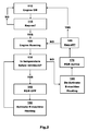
- Fig.2 there is shown in outline form a method for reducing NOx emissions from an engine such as the engine 10 in accordance with this invention.
- the method starts in box 110 with the engine 10 not running that is to say, the engine 10 is 'Off'.
- a 'key-on' event is an event that will change the state of the engine 10 from 'Off' to 'On'. That is to say, the engine 10 following a 'key-on' event will be running.
- a 'key-on' event is the result of a driver of a vehicle, such as the vehicle 5, activating an ignition switch it will be appreciated that the specific mechanism used to start the engine 10 is not important.
- the method advances to box 130 to check whether the current engine temperature as sensed by the intake temperature sensor 7 and the cylinder head sensor 8 and the current exhaust gas temperature as measured by one or more exhaust gas sensors 6a, 6b, 6c are below minimum effective EGR usage temperatures.
- Box 130 therefore comprises of tests to see whether the current measured temperatures are above or below predefined limits and based upon the result of these tests the method either advances to box 140 or 160.
- the method advances to box 140 where it is ensured that any EGR flow is prevented by, for example closing or keeping closed EGR flow control valves such as the HPEGR and LPEGR valves 32 and 42 shown on Fig.1 . Opening the HPEGR and LPEGR valves 32 and 42 at this time would likely result in combustion instability and/ or condensation being inducted into the compressor 20c.
- the method then advances from box 140 to box 150 where an electric machine, such as the integrated starter-generator 18, is operated as a generator to load the engine 10.
- an electric machine such as the integrated starter-generator 18
- the additional load applied by the integrated starter-generator 18 will cause the engine temperature and the exhaust gas temperature to increase more rapidly than would normally be the case.
- the method returns to box 130 to recheck the measured engine and exhaust gas temperatures and will cycle around the boxes 130, 140 and 150 until the measured engine and exhaust gas temperatures exceed the predefined temperature limit for that respective parameter.
- box 160 when exhaust gas heating by the use of the integrated starter-generator 18 is already active then it is deactivated and the integrated starter-generator 18 is then controlled normally to meet the demands of the vehicle 5.
- box 170 Irrespective of the route followed to reach box 160, from box 160 the method advances to box 170 where EGR is activated. That is to say, exhaust gas recirculation flow is permitted. It will be appreciated that if the engine 10 is fitted with low and high pressure EGR then in box 170 it could be LPEGR that is enabled, HPEGR that is enabled or both depending upon the temperature limit that has been reached.
- box 180 it is checked whether a 'key-off' event has occurred and if it has the method returns to box 110 with the engine 10 'Off' and if it has not the method returns to box 120 with the engine 10 running.
Abstract
Description
- This invention relates to a method for reducing NOx emissions from an engine and, in particular, to a method of reducing NOx emissions from an engine after a start-up from cold.
- It is known from, for example,
US Patent 6,829,888 that an electric machine can be used to assist with heating the exhaust gas flow from an engine in order to assist with catalyst light-off. - The use of high pressure exhaust gas recirculation (HPEGR) or low pressure exhaust gas recirculation (LPEGR) at the earliest possible moment during a vehicle drive cycle helps to reduce NOx emissions. The requirement for early EGR has been increased by the need to satisfy Euro 6.2 emission requirements and real-world driving cycles. The engine operating range in terms of engine speed and engine load and the temperature range over which EGR flow is required are both increased with the need to meet these new requirements.
- One problem associated with the early use of EGR is that it can result in combustion instability if the temperature of the gas inducted into the engine is low such as following a cold start.
- A second problem associated with the early use of LP EGR in the case of an engine having forced induction using a compressor is that it can result in the formation of condensation upstream of the compressor. The formation of such condensation can seriously damage the fast rotating blades of the compressor.
- The inventors have realised that the use of exhaust gas heating such as proposed in
US Patent 6,829,888 can be beneficially used to enable earlier use of exhaust gas recirculation. - It is an object of this invention to provide a method of reducing engine NOx emissions after a cold start by facilitating the early use of exhaust gas recirculation without causing significant combustion instability or damaging condensation.
- According to a first aspect of the invention there is provided a method of enabling earlier use of exhaust gas recirculation to reduce NOx emissions from an engine of a motor vehicle following a cold start of the engine, the method comprising using a battery of the motor vehicle to apply an electrical load to an electric machine driven by the engine, using the electric machine as a generator to charge the battery and to apply a load to the engine to increase the rate at which the engine temperature and the exhaust gas temperature increase identifying whether at least one of the engine temperature and exhaust gas temperature is too low for the effective use of exhaust gas recirculation and, if one of engine temperature and exhaust gas temperature is too low for the effective use of exhaust gas recirculation, preventing exhaust gas recirculation and when the engine temperature and the exhaust gas temperature are high enough to permit effective use of exhaust gas recirculation, activating exhaust gas recirculation and terminating use of the electric machine as a generator.
- Irrespective of engine temperature and exhaust gas temperature, the use of the electric machine as a generator may be terminated if the load applied to the engine has increased to a level where the engine is warming up sufficiently rapidly that additional heating is not required.
- Alternatively, irrespective of engine temperature and exhaust gas temperature, the use of the electric machine as a generator may be terminated if a state of charge of a battery connected to the electric machine reaches a maximum safe limit.
- The electric machine may be an integrated starter-generator drivingly connected to the engine.
- The engine temperature and the exhaust gas temperature may be high enough to permit effective use of exhaust gas recirculation when the use of exhaust gas recirculation will not cause combustion instability in the engine.
- The engine may be a forced induction engine having a compressor, the exhaust gas recirculation may be a low pressure exhaust gas recirculation that returns exhaust gas to a position upstream from the compressor and the engine temperature and the exhaust gas temperature may be high enough to permit effective use of exhaust gas recirculation if the use of low pressure exhaust gas recirculation will not cause condensation to be inducted into the compressor.
- According to a second aspect of the invention there is provided a motor vehicle having a battery, an engine drivingly connected to an electric machine, an electronic controller and an exhaust gas recirculation system to recirculate exhaust gas from an exhaust side of the engine to an intake side of the engine, the exhaust gas recirculation system including an exhaust gas recirculation valve to control the flow of recirculated exhaust gas wherein the electronic controller is arranged to use the battery of the motor vehicle to apply an electrical load to the electric machine, use the electric machine as a generator to charge the battery and to apply a load to the engine to increase the rate at which the engine temperature and the exhaust gas temperature increase, identify whether at least one of engine temperature and exhaust gas temperature is too low for the effective use of exhaust gas recirculation and, if one of engine temperature and exhaust gas temperature is too low for the effective use of exhaust gas recirculation, the electronic controller is arranged to prevent exhaust gas recirculation by closing the exhaust gas recirculation valve and when the engine temperature and the exhaust gas temperature are high enough to permit the effective use of exhaust gas recirculation, the electronic controller is arranged to activate exhaust gas recirculation by opening the exhaust gas recirculation valve and to terminate the use of the electric machine as a generator.
- Irrespective of engine temperature and exhaust gas temperature, the electronic controller may be further arranged to terminate the use of the electric machine as a generator if the load applied to the engine has increased to a level where the engine is warming up sufficiently rapidly that additional heating is not required.
- Irrespective of engine temperature and exhaust gas temperature, the electronic controller may be further arranged to monitor the state of charge of a battery connected to the electric machine and may be further arranged to terminate use of the electric machine as a generator if a state of charge of a battery reaches a maximum safe limit.
- The electric machine may be an integrated starter-generator.
- The engine temperature and the exhaust gas temperature may be high enough to permit the effective use of exhaust gas recirculation when the use of exhaust gas recirculation will not cause combustion instability in the engine.
- The engine may be a forced induction engine having a compressor to compress the flow of air entering the engine, the exhaust gas recirculation system may be a low pressure exhaust gas recirculation system that returns exhaust gas to an intake system for the engine at a position upstream from the compressor and the engine temperature and the exhaust gas temperature may be high enough to permit the effective use of exhaust gas recirculation if the use of low pressure exhaust gas recirculation will not cause the induction of condensation into the compressor.
- The compressor may be part of a turbocharger having a turbine to drive the compressor and the exhaust gas may be extracted from an exhaust system of the engine at position downstream from the turbine of the turbocharger.
- The exhaust gas system may be a high pressure exhaust gas system, the engine may have a turbocharger having a compressor driven by a turbine for increasing the flow of air through an intake system of the engine, recirculated exhaust gas may be extracted from an exhaust system of the engine at a position upstream from the turbine of the turbocharger and be returned to the intake system of the engine downstream from the compressor.
- The invention will now be described by way of example with reference to the accompanying drawing of which:-
-
Fig.1 is a schematic diagram of a motor vehicle according to a second aspect of the invention; and -
Fig.2 is a high level flow chart of a method of enabling earlier use of exhaust gas recirculation to reduce NOx emissions from an engine following a cold start of the engine in accordance with a first aspect of the invention. - With reference to
Fig.1 there is shown amotor vehicle 5 having a forced induction engine in the form of aturbocharged engine 10. Theengine 10 has an intake system through which atmospheric air flows to theengine 10. The intake system comprises a number of intake conduits, anair filter 12, acompressor 20c of aturbocharger 20, athrottle valve 13, anintercooler 14 and anintake manifold 15. The intake conduits are used to connect together the various components of the intake system used to flow air to theengine 10. - Air enters the intake system via the
air filter 12, is compressed by thecompressor 20c and flows via thethrottle valve 13 to theintercooler 14 and then to theintake manifold 15 of theengine 10. - Fuel is injected into the
engine 10 by a number of fuel injectors (not shown) and the products of combustion in the form of exhaust gas flows via anexhaust manifold 11 to aturbine 20t of theturbocharger 20. - After passing through the
turbine 20t the exhaust gas flows through one ormore aftertreatment devices 16 to atailpipe 17 and from thetailpipe 17 to atmosphere. - A
HPEGR circuit 30 is arranged to extract exhaust gas from a position between theexhaust manifold 11 and theturbine 20t and flow the extracted exhaust gas via anexhaust gas cooler 31 to a high pressure exhaustgas recirculation valve 32. When the high pressure exhaustgas recirculation valve 32 is open the high pressure exhaust gas can flow into the intake path upstream from theintake manifold 15 and downstream from theintercooler 14 and thecompressor 20c. - A
LPEGR circuit 40 is arranged to extract exhaust gas from a position between theturbine 20t and theaftertreatment devices 16 and flow the extracted exhaust gas via anexhaust gas cooler 41 to a low pressure exhaustgas recirculation valve 42. When the low pressure exhaustgas recirculation valve 42 is open the low pressure exhaust gas can flow into the intake path. - It will be appreciated that if the
aftertreatment devices 16 include a particulate trap then the exhaust gas for the LPEGR would preferably be extracted downstream from the particulate trap as that would reduce the amount of soot reaching thecompressor 20c and so reduce contamination of the blades of thecompressor 20c. If no particulate trap is present then, as an alternative, a particulate filter could be included between theexhaust gas cooler 41 and the extraction point of the exhaust gas. - An electric machine is drivingly connected to the
engine 10 and in the case of this example is in the form of an integrated starter-generator 18. The integrated starter-generator 18 is, in the case of this example, belt driven from a crankshaft of theengine 10 but it will be appreciated that it could alternatively be chain driven or gear driven. - The integrated starter-
generator 18 can be used to generate electricity or generate torque depending upon the mode in which it is operating. Abattery 19 is connected to the integrated starter-generator 18 along with associated control electronics formed as part of a centralelectronic controller 50. When the integrated starter-generator 18 is operating as a generator it charges thebattery 19 and, when the integrated starter-generator 18 is operating as a motor, thebattery 19 provides electrical energy to the integrated starter-generator 18. Theelectronic controller 50 monitors the state of charge (SOC) of thebattery 19 and controls the integrated starter-generator 18 to ensure that the state of charge of the battery remains within safe upper and lower limits. - The
electronic controller 50 is arranged to control operation of the integrated starter-generator 18, the operating state of the high pressure exhaustgas recirculation valve 32, the operating state of the low pressure exhaustgas recirculation valve 42 and the rotary position of thethrottle valve 13. It will be appreciated that the high and low pressure exhaustgas recirculation valves - The
electronic controller 50 is also used to control normal operation of the engine. - The
electronic controller 50 receives inputs from a number of sensors such as, for example, a mass air flow sensor (not shown), an engine speed sensor (not shown), an accelerator pedal position sensor (not shown), a Lambda sensor (not shown), three exhaustgas temperature sensors intake temperature sensor 7 and an engine cylinderhead temperature sensor 8. - The connections between the
electronic controller 50 and the various sensors and components it controls are not shown inFig.1 to simplify and improve understanding of the figure. - It will be appreciated that the
electronic controller 50 may comprise of several interconnected electronic controllers and need not be a single unit as shown inFig.1 . - Operation of the
electronic controller 50 so far as this invention is concerned is as follows. - When the temperature of the
engine 10 is sensed to be below a normal operating temperature following an engine start, heating is required in order to reduce the time delay between engine start and the time that EGR can be used to help reduce NOx emissions. - There are two important points to be considered when deciding whether exhaust gas recirculation can be used effectively. Firstly, determining when combustion is likely to be unstable and secondly determining if the recirculated exhaust gas will be hot enough to help with combustion stability.
- Combustion will be unstable if in-cylinder gas temperatures are low which will be the case if the temperature of the engine is low. The engine temperature can be deduced by using the output from the cylinder head temperature sensor 8 (or an engine coolant sensor) which provide an indication whether the cylinder walls are cold and by using the
intake temperature sensor 7 which provides an indication of whether the temperature of the inducted gas is low. - Using a combination of these measurements a prediction can be made as to whether unstable combustion would be likely from the use of EGR.
- A further factor to be considered is whether the temperature of the exhaust gas is high enough to increase the inducted gas temperature if EGR is used. The temperature of the exhaust gas can be deduced from the outputs from the
exhaust gas sensors - It will be appreciated that there is a trade-off between combustion stability and mixture dilution that also has to be taken into account when deciding whether to use EGR and the amount of EGR to use. That is to say, adding hot recirculated exhaust gas will increase the mobility of the molecules of fuel and air and therefore helps improve combustion stability but the addition of inert gas to the intake fuel/air mixture will dilute it and so the benefit of adding the hot recirculated exhaust gas has to be weighed against the diluting effect of the inert gas.
- However, in all cases it is advantageous to speed up the process of heating of the
engine 10 and theelectronic controller 50 is arranged to operate the integrated starter-generator 18 as a generator in order to do this. - The use of the integrated starter-
generator 18 as a generator will increase the load upon theengine 10 and this will result in an increased torque demand for theengine 10 which is met by supplying more fuel to theengine 10. The extra fuel increases the temperature of the engine and the temperature of the exhaust gas more quickly than it would if the air/fuel ratio were to be optimised for good fuel economy as is normally the case. - As referred to above the
electronic controller 50 is arranged to use thetemperature sensors electronic controller 50 is arranged to open the high pressure exhaustgas recirculation valve 32. - The
electronic controller 50 in the case of this example is further arranged when the sensed exhaust gas temperature is above a temperature limit (TLP) below which condensation is likely to be caused if LPEGR is used, to open the low pressure exhaustgas recirculation valve 42. - It will be appreciated that the temperature of the LPEGR gas will be lower than the temperature of the HPEGR gas for the same exhaust gas temperature due to the difference between the HPEGR gas flow path from the exhaust side of the
engine 10 to the intake side of theengine 10 and the LPEGR gas flow path from the exhaust side of theengine 10 to the intake side of theengine 10. - It is generally desirable to use LPEGR in preference to HPEGR whenever possible because LPEGR provides a potential fuel economy benefit and is better mixed with atmospheric air therefore HPEGR is sometimes terminated as soon as LPEGR can be utilised.
- The
electronic controller 50 is further arranged to stop the use of the integrated starter-generator 18 as a generator when at least one of several conditions is present:- - a/ the temperature of the exhaust gas exiting the
engine 10 is above the low pressure and high pressure temperature limits (TLP) and (THP) respectively and the temperature of theengine 10 as sensed by thecylinder head sensor 8 and theintake temperature sensor 7 exceed predefined temperature limits; - b/ the load applied to the
engine 10 has increased to a level where theengine 10 is warming up sufficiently rapidly that additional heating is not required; and - c/ if the state of charge of the
battery 19 reaches an upper safe charge limit indicating that there is substantially no capacity left in thebattery 19 to store further electrical energy. - It will be appreciated that the invention is not limited to use with an engine having both low and high pressure exhaust gas recirculation. For example and without limitation, the invention can be applied with advantage to an engine with or without forced induction having only high pressure exhaust gas recirculation or an engine having forced induction and having only low pressure exhaust gas recirculation.
- With reference to
Fig.2 there is shown in outline form a method for reducing NOx emissions from an engine such as theengine 10 in accordance with this invention. - The method starts in
box 110 with theengine 10 not running that is to say, theengine 10 is 'Off'. - The method advances to
box 115 to check whether a key-on event has occurred. A 'key-on' event is an event that will change the state of theengine 10 from 'Off' to 'On'. That is to say, theengine 10 following a 'key-on' event will be running. Although in some cases a 'key-on' event is the result of a driver of a vehicle, such as thevehicle 5, activating an ignition switch it will be appreciated that the specific mechanism used to start theengine 10 is not important. - If when checked in
box 115 there has been no 'key-on' event it will return tobox 110 and theengine 10 remains in the 'Off' state. - However, if when checked in
box 115, there has been a 'key-on' event then theengine 10 will be started and the method advances tobox 120 where theengine 10 is now running. - From
box 120 the method advances tobox 130 to check whether the current engine temperature as sensed by theintake temperature sensor 7 and thecylinder head sensor 8 and the current exhaust gas temperature as measured by one or moreexhaust gas sensors - It will be appreciated that, in the case of the exhaust gas temperature, there could be a single temperature limit or multiple temperature limits. For example, if the
engine 10 has, as shown inFig.1 , both low pressure and high pressure EGR circuits then the exhaust gas temperature required to prevent unstable combustion could be different to that required to prevent condensation upstream from a compressor, such as thecompressor 20c. -
Box 130 therefore comprises of tests to see whether the current measured temperatures are above or below predefined limits and based upon the result of these tests the method either advances tobox - If one or more of the current measured temperatures is below the predefined limit for that parameter the method advances to
box 140 where it is ensured that any EGR flow is prevented by, for example closing or keeping closed EGR flow control valves such as the HPEGR andLPEGR valves Fig.1 . Opening the HPEGR andLPEGR valves compressor 20c. - The method then advances from
box 140 tobox 150 where an electric machine, such as the integrated starter-generator 18, is operated as a generator to load theengine 10. The additional load applied by the integrated starter-generator 18 will cause the engine temperature and the exhaust gas temperature to increase more rapidly than would normally be the case. - From
box 150 the method returns tobox 130 to recheck the measured engine and exhaust gas temperatures and will cycle around theboxes - If in
box 130 all of the measured engine and exhaust gas temperatures exceed their respective temperature limit, the method will advance tobox 160. - In
box 160 when exhaust gas heating by the use of the integrated starter-generator 18 is already active then it is deactivated and the integrated starter-generator 18 is then controlled normally to meet the demands of thevehicle 5. - However, if no exhaust gas heating is active when
box 160 is entered, because the route tobox 160 is frombox 120 tobox 130 and then tobox 160, the integrated starter-generator 18 is controlled normally to meet the demands of thevehicle 5. - Irrespective of the route followed to reach
box 160, frombox 160 the method advances tobox 170 where EGR is activated. That is to say, exhaust gas recirculation flow is permitted. It will be appreciated that if theengine 10 is fitted with low and high pressure EGR then inbox 170 it could be LPEGR that is enabled, HPEGR that is enabled or both depending upon the temperature limit that has been reached. - From
box 170 the method advances tobox 180 where it is checked whether a 'key-off' event has occurred and if it has the method returns to box 110 with the engine 10 'Off' and if it has not the method returns to box 120 with theengine 10 running. - It will be appreciated that as soon as the
engine 10 has warmed up sufficiently the tests inbox 130 will always result in the method advancing tobox 160 and during normal hot running of the engine the method will therefore cycle continuously throughboxes - It will be appreciated that in addition to the tests described in
box 130 there could be additional tests used to determine whether the use of the integrated starter-generator 18 should be terminated such as, for example, whether the state of charge of thebattery 19 has reached an upper safe limit or whether the torque demand upon theengine 10 is sufficiently high that additional heating is no longer required. - It will be appreciated by those skilled in the art that although the invention has been described by way of example with reference to one or more embodiments it is not limited to the disclosed embodiments and that alternative embodiments could be constructed without departing from the scope of the invention as defined by the appended claims.
Claims (14)
- A method of enabling earlier use of exhaust gas recirculation to reduce NOx emissions from an engine 10 of a motor vehicle 5 following a cold start of the engine, wherein the method comprises using a battery 19 of the motor vehicle to apply an electrical load to an electric machine 18 driven by the engine, using the electric machine as a generator to charge the battery and to apply a load to the engine to increase the rate at which the engine temperature and the exhaust gas temperature increase identifying whether at least one of the engine temperature and exhaust gas temperature is too low for the effective use of exhaust gas recirculation and, if one of engine temperature and exhaust gas temperature is too low for the effective use of exhaust gas recirculation, preventing exhaust gas recirculation and when the engine temperature and the exhaust gas temperature are high enough to permit effective use of exhaust gas recirculation, activating exhaust gas recirculation and terminating use of the electric machine as a generator.
- A method as claimed in claim 1 wherein, irrespective of engine temperature and exhaust gas temperature, the use of the electric machine as a generator is terminated if the load applied to the engine has increased to a level where the engine is warming up sufficiently rapidly that additional heating is not required.
- A method as claimed in claim 1 wherein, irrespective of engine temperature and exhaust gas temperature, the use of the electric machine as a generator is terminated if a state of charge of a battery connected to the electric machine reaches a maximum safe limit.
- A method as claimed in any of claims 1 to 3 wherein the electric machine is an integrated starter-generator drivingly connected to the engine.
- A method as claimed in any of claims 1 to 4 wherein the engine temperature and the exhaust gas temperature are high enough to permit effective use of exhaust gas recirculation when the use of exhaust gas recirculation will not cause combustion instability in the engine.
- A method as claimed in any of claims 1 to 4 wherein the engine has a compressor 20c, the exhaust gas recirculation is low pressure exhaust gas recirculation 40 that returns exhaust gas to a position upstream from the compressor and the engine temperature and the exhaust gas temperature are high enough to permit effective use of exhaust gas recirculation if the use of low pressure exhaust gas recirculation will not cause condensation to be inducted into the compressor.
- A motor vehicle 5 having a battery 19, an engine 10drivingly connected to an electric machine 18, an electronic controller 50 and an exhaust gas recirculation system 30,40 to recirculate exhaust gas from an exhaust side 11 of the engine to an intake side 15 of the engine, the exhaust gas recirculation system including an exhaust gas recirculation valve 32,42 to control the flow of recirculated exhaust gas wherein the electronic controller is arranged to use the battery of the motor vehicle to apply an electrical load to the electric machine, use the electric machine as a generator to charge the battery and to apply a load to the engine to increase the rate at which the engine temperature and the exhaust gas temperature increase, identify whether at least one of engine temperature and exhaust gas temperature is too low for the effective use of exhaust gas recirculation and, if one of engine temperature and exhaust gas temperature is too low for the effective use of exhaust gas recirculation, the electronic controller is arranged to prevent exhaust gas recirculation by closing the exhaust gas recirculation valve and when the engine temperature and the exhaust gas temperature are high enough to permit the effective use of exhaust gas recirculation, the electronic controller is arranged to activate exhaust gas recirculation by opening the exhaust gas recirculation valve and to terminate the use of the electric machine as a generator.
- A vehicle as claimed in claim 7 wherein, irrespective of engine temperature and exhaust gas temperature, the electronic controller is further arranged to terminate the use of the electric machine as a generator if the load applied to the engine has increased to a level where the engine is warming up sufficiently rapidly that additional heating is not required.
- A vehicle as claimed in claim 7 wherein, irrespective of engine temperature and exhaust gas temperature, the electronic controller is further arranged to monitor the state of charge of a battery connected to the electric machine and to terminate use of the electric machine as a generator if a state of charge of a battery reaches a maximum safe limit.
- A vehicle as claimed in any of claims 7 to 9 wherein the electric machine is an integrated starter-generator.
- A vehicle as claimed in any of claims 7 to 10 wherein the engine temperature and the exhaust gas temperature are high enough to permit the effective use of exhaust gas recirculation when the use of exhaust gas recirculation will not cause combustion instability in the engine.
- A vehicle as claimed in any of claims 7 to 10 wherein the engine has a compressor 20c to compress the flow of air entering the engine, the exhaust gas recirculation system is a low pressure exhaust gas recirculation system that returns exhaust gas to an intake system for the engine at a position upstream from the compressor and the engine temperature and the exhaust gas temperature are high enough to permit the effective use of exhaust gas recirculation if the use of low pressure exhaust gas recirculation will not cause the induction of condensation into the compressor.
- A vehicle as claimed in claim 12 wherein the compressor is part of a turbocharger 20 having a turbine 20t to drive the compressor and the exhaust gas is extracted from an exhaust system 16,17 of the engine at position downstream from the turbine of the turbocharger.
- A vehicle as claimed in claim 11 wherein the exhaust gas system is a high pressure exhaust gas system, the engine has a turbocharger having a compressor driven by a turbine for increasing the flow of air through an intake system of the engine, recirculated exhaust gas is extracted from an exhaust system of the engine at a position upstream from the turbine of the turbocharger and is returned to the intake system of the engine downstream from the compressor.
Applications Claiming Priority (1)
| Application Number | Priority Date | Filing Date | Title |
|---|---|---|---|
| GB1514121.1A GB2541200A (en) | 2015-08-11 | 2015-08-11 | A method of reducing engine NOx emissions |
Publications (2)
| Publication Number | Publication Date |
|---|---|
| EP3130787A1 true EP3130787A1 (en) | 2017-02-15 |
| EP3130787B1 EP3130787B1 (en) | 2018-11-28 |
Family
ID=54200494
Family Applications (1)
| Application Number | Title | Priority Date | Filing Date |
|---|---|---|---|
| EP16275113.5A Active EP3130787B1 (en) | 2015-08-11 | 2016-08-09 | A method of reducing engine nox emissions |
Country Status (6)
| Country | Link |
|---|---|
| US (1) | US10247115B2 (en) |
| EP (1) | EP3130787B1 (en) |
| CN (1) | CN106438065B (en) |
| GB (1) | GB2541200A (en) |
| MX (1) | MX365518B (en) |
| RU (1) | RU2719409C2 (en) |
Cited By (1)
| Publication number | Priority date | Publication date | Assignee | Title |
|---|---|---|---|---|
| SE1951425A1 (en) * | 2019-12-11 | 2021-06-12 | Scania Cv Ab | Method and control arrangement for controlling egr |
Families Citing this family (7)
| Publication number | Priority date | Publication date | Assignee | Title |
|---|---|---|---|---|
| US20190002117A1 (en) * | 2017-06-30 | 2019-01-03 | General Electric Company | Propulsion system for an aircraft |
| EP3476680A1 (en) * | 2017-10-24 | 2019-05-01 | Volvo Car Corporation | Method for heating an exhaust aftertreatment system and a hybrid vehicle adapted to heat an exhaust aftertreatment system |
| CN108357489B (en) * | 2018-03-21 | 2019-12-06 | 潍柴动力股份有限公司 | Post-processing temperature control system and method |
| US11377088B2 (en) * | 2018-04-02 | 2022-07-05 | Cummins Inc. | Electric vehicles with engines and interaction with aftertreatment |
| JP7047597B2 (en) * | 2018-05-25 | 2022-04-05 | トヨタ自動車株式会社 | Internal combustion engine |
| US10975790B2 (en) | 2019-08-26 | 2021-04-13 | Ford Global Technologies, Llc | Systems and methods for controlling boost during an engine cold start |
| CN114508432A (en) * | 2022-03-21 | 2022-05-17 | 潍柴动力股份有限公司 | Energy control method and device for WLTC (wafer level temperature controller) cycle cold start stage |
Citations (5)
| Publication number | Priority date | Publication date | Assignee | Title |
|---|---|---|---|---|
| EP1182074A2 (en) * | 2000-08-25 | 2002-02-27 | Ford Global Technologies, Inc. | Method of operating a hybrid electric vehicle to reduce emissions |
| EP1205647A1 (en) * | 2000-11-03 | 2002-05-15 | Ford Global Technologies, Inc., A subsidiary of Ford Motor Company | Method for regenerating the particulate filter of a Diesel engine |
| US20030056497A1 (en) * | 2001-09-26 | 2003-03-27 | Johannes Kuenstler | Method for controlling the starting of an internal combustion engine |
| EP1452712A1 (en) * | 2003-02-21 | 2004-09-01 | Toyota Jidosha Kabushiki Kaisha | Catalyst warm up control for diesel engine |
| DE102007038242A1 (en) * | 2007-08-13 | 2009-02-19 | Iav Gmbh Ingenieurgesellschaft Auto Und Verkehr | Method for recirculating exhaust gas from outlet line into inlet line of internal combustion engine, involves arranging compressor in inlet line and exhaust gas turbocharger in outlet line |
Family Cites Families (15)
| Publication number | Priority date | Publication date | Assignee | Title |
|---|---|---|---|---|
| JPS5867955A (en) * | 1981-10-20 | 1983-04-22 | Nissan Motor Co Ltd | Exhaust gas recirculating device of diesel engine |
| EP0516692B1 (en) | 1990-02-27 | 1997-01-15 | Orbital Engine Company (Australia) Pty. Ltd. | Exhaust emission control |
| JP2000297669A (en) | 1999-04-12 | 2000-10-24 | Fuji Heavy Ind Ltd | Control device of hybrid vehicle |
| JP4396795B2 (en) | 2000-09-22 | 2010-01-13 | コベルコ建機株式会社 | Canopy strut structure of construction machinery |
| US7007460B2 (en) * | 2003-08-11 | 2006-03-07 | General Motors Corporation | Apparatus and method for accelerated exhaust system component heating |
| DE10359674A1 (en) | 2003-12-18 | 2005-07-28 | Siemens Ag | Method for increasing the exhaust gas temperature of internal combustion engines |
| JP4687709B2 (en) * | 2007-04-25 | 2011-05-25 | トヨタ自動車株式会社 | Exhaust gas purification device for internal combustion engine |
| JP4325704B2 (en) | 2007-06-06 | 2009-09-02 | トヨタ自動車株式会社 | Exhaust gas purification system for internal combustion engine |
| US20090033095A1 (en) * | 2007-08-01 | 2009-02-05 | Deepak Aswani | Regenerating an engine exhaust gas particulate filter in a hybrid electric vehicle |
| US8042326B2 (en) | 2007-08-17 | 2011-10-25 | GM Global Technology Operations LLC | Intake air heater for assisting DPF regeneration |
| JP4450257B2 (en) * | 2008-07-14 | 2010-04-14 | 三菱自動車工業株式会社 | Exhaust purification device |
| US8479510B2 (en) * | 2011-06-09 | 2013-07-09 | Ford Global Technologies, Llc | Exhaust gas recirculation system |
| DE102012015259A1 (en) * | 2012-08-01 | 2014-02-06 | Daimler Ag | Process for treating exhaust gas and arrangement of an exhaust system on an internal combustion engine |
| US9255550B2 (en) * | 2013-03-08 | 2016-02-09 | GM Global Technology Operations LLC | Emission system and method of selectively directing exhaust gas and air within an internal combustion engine |
| US9109505B2 (en) * | 2013-08-13 | 2015-08-18 | Ford Global Technologies, Llc | Methods and systems for condensation control |
-
2015
- 2015-08-11 GB GB1514121.1A patent/GB2541200A/en not_active Withdrawn
-
2016
- 2016-08-04 CN CN201610633096.4A patent/CN106438065B/en active Active
- 2016-08-09 EP EP16275113.5A patent/EP3130787B1/en active Active
- 2016-08-09 RU RU2016132768A patent/RU2719409C2/en active
- 2016-08-10 MX MX2016010353A patent/MX365518B/en active IP Right Grant
- 2016-08-10 US US15/233,329 patent/US10247115B2/en active Active
Patent Citations (5)
| Publication number | Priority date | Publication date | Assignee | Title |
|---|---|---|---|---|
| EP1182074A2 (en) * | 2000-08-25 | 2002-02-27 | Ford Global Technologies, Inc. | Method of operating a hybrid electric vehicle to reduce emissions |
| EP1205647A1 (en) * | 2000-11-03 | 2002-05-15 | Ford Global Technologies, Inc., A subsidiary of Ford Motor Company | Method for regenerating the particulate filter of a Diesel engine |
| US20030056497A1 (en) * | 2001-09-26 | 2003-03-27 | Johannes Kuenstler | Method for controlling the starting of an internal combustion engine |
| EP1452712A1 (en) * | 2003-02-21 | 2004-09-01 | Toyota Jidosha Kabushiki Kaisha | Catalyst warm up control for diesel engine |
| DE102007038242A1 (en) * | 2007-08-13 | 2009-02-19 | Iav Gmbh Ingenieurgesellschaft Auto Und Verkehr | Method for recirculating exhaust gas from outlet line into inlet line of internal combustion engine, involves arranging compressor in inlet line and exhaust gas turbocharger in outlet line |
Cited By (2)
| Publication number | Priority date | Publication date | Assignee | Title |
|---|---|---|---|---|
| SE1951425A1 (en) * | 2019-12-11 | 2021-06-12 | Scania Cv Ab | Method and control arrangement for controlling egr |
| SE543849C2 (en) * | 2019-12-11 | 2021-08-10 | Scania Cv Ab | Method and control arrangement for controlling egr |
Also Published As
| Publication number | Publication date |
|---|---|
| GB201514121D0 (en) | 2015-09-23 |
| RU2719409C2 (en) | 2020-04-17 |
| CN106438065A (en) | 2017-02-22 |
| RU2016132768A3 (en) | 2020-02-06 |
| US10247115B2 (en) | 2019-04-02 |
| CN106438065B (en) | 2021-10-26 |
| RU2016132768A (en) | 2018-02-12 |
| US20170045004A1 (en) | 2017-02-16 |
| GB2541200A (en) | 2017-02-15 |
| MX365518B (en) | 2019-06-05 |
| EP3130787B1 (en) | 2018-11-28 |
| MX2016010353A (en) | 2017-04-27 |
Similar Documents
| Publication | Publication Date | Title |
|---|---|---|
| EP3130787B1 (en) | A method of reducing engine nox emissions | |
| RU2579616C2 (en) | Engine start method and engine system | |
| US8978378B2 (en) | Method and system for reducing turbocharger noise during cold start | |
| US10054069B2 (en) | Method and apparatus for model based control of electrical boosting system | |
| US20190376461A1 (en) | Systems and methods for expediting engine warming | |
| CN105888805B (en) | Method and device for increasing and/or decreasing the exhaust gas temperature of an internal combustion engine | |
| US9574524B2 (en) | Method and internal combustion engine system for keeping an exhaust gas aftertreatment system within its working temperature range | |
| RU2702057C2 (en) | Operating method of internal combustion engine (embodiments) and internal combustion engine | |
| US9144761B2 (en) | Method and device for interior heating in a motor vehicle | |
| EP2986834B1 (en) | Method and apparatus for exhaust gas aftertreatment device warning | |
| CN102189991B (en) | Control system and method for oxygen sensor heater control | |
| US20150083093A1 (en) | Method and Apparatus for Controlling the Starting of an Internal Combustion Engine | |
| KR20160097253A (en) | Exhaust line for an internal combustion engine and internal combustion engine comprising such an exhaust line | |
| US7980062B2 (en) | Cold start white smoke aftertreatment protection | |
| JP5350907B2 (en) | Water pump control device | |
| JP5282695B2 (en) | Control device for an internal combustion engine with a supercharger | |
| JP2019027306A (en) | Control device for internal combustion engine | |
| US8447501B2 (en) | Method for managing the automatic stoppage of an automobile | |
| JP4720779B2 (en) | Exhaust temperature reduction control device and method | |
| JP6795933B2 (en) | Turbo speed control device and turbo speed control method | |
| JP6437558B2 (en) | Method and starter for cold starting a heat engine | |
| JP2005299470A (en) | Warmup control method of low compression ratio engine for diesel hybrid vehicle | |
| JP2015121156A (en) | Control device of internal combustion engine | |
| JP2023053487A (en) | Engine control device |
Legal Events
| Date | Code | Title | Description |
|---|---|---|---|
| PUAI | Public reference made under article 153(3) epc to a published international application that has entered the european phase |
Free format text: ORIGINAL CODE: 0009012 |
|
| STAA | Information on the status of an ep patent application or granted ep patent |
Free format text: STATUS: THE APPLICATION HAS BEEN PUBLISHED |
|
| AK | Designated contracting states |
Kind code of ref document: A1 Designated state(s): AL AT BE BG CH CY CZ DE DK EE ES FI FR GB GR HR HU IE IS IT LI LT LU LV MC MK MT NL NO PL PT RO RS SE SI SK SM TR |
|
| AX | Request for extension of the european patent |
Extension state: BA ME |
|
| STAA | Information on the status of an ep patent application or granted ep patent |
Free format text: STATUS: REQUEST FOR EXAMINATION WAS MADE |
|
| 17P | Request for examination filed |
Effective date: 20170816 |
|
| RAV | Requested validation state of the european patent: fee paid |
Extension state: MD Effective date: 20170816 Extension state: MA Effective date: 20170816 |
|
| RAX | Requested extension states of the european patent have changed |
Extension state: ME Payment date: 20170816 Extension state: BA Payment date: 20170816 |
|
| RBV | Designated contracting states (corrected) |
Designated state(s): AL AT BE BG CH CY CZ DE DK EE ES FI FR GB GR HR HU IE IS IT LI LT LU LV MC MK MT NL NO PL PT RO RS SE SI SK SM TR |
|
| STAA | Information on the status of an ep patent application or granted ep patent |
Free format text: STATUS: EXAMINATION IS IN PROGRESS |
|
| 17Q | First examination report despatched |
Effective date: 20180416 |
|
| GRAP | Despatch of communication of intention to grant a patent |
Free format text: ORIGINAL CODE: EPIDOSNIGR1 |
|
| STAA | Information on the status of an ep patent application or granted ep patent |
Free format text: STATUS: GRANT OF PATENT IS INTENDED |
|
| INTG | Intention to grant announced |
Effective date: 20180628 |
|
| GRAS | Grant fee paid |
Free format text: ORIGINAL CODE: EPIDOSNIGR3 |
|
| GRAA | (expected) grant |
Free format text: ORIGINAL CODE: 0009210 |
|
| STAA | Information on the status of an ep patent application or granted ep patent |
Free format text: STATUS: THE PATENT HAS BEEN GRANTED |
|
| AK | Designated contracting states |
Kind code of ref document: B1 Designated state(s): AL AT BE BG CH CY CZ DE DK EE ES FI FR GB GR HR HU IE IS IT LI LT LU LV MC MK MT NL NO PL PT RO RS SE SI SK SM TR |
|
| AX | Request for extension of the european patent |
Extension state: BA ME |
|
| REG | Reference to a national code |
Ref country code: CH Ref legal event code: EP |
|
| REG | Reference to a national code |
Ref country code: AT Ref legal event code: REF Ref document number: 1070534 Country of ref document: AT Kind code of ref document: T Effective date: 20181215 |
|
| REG | Reference to a national code |
Ref country code: DE Ref legal event code: R096 Ref document number: 602016007585 Country of ref document: DE |
|
| REG | Reference to a national code |
Ref country code: IE Ref legal event code: FG4D |
|
| REG | Reference to a national code |
Ref country code: NL Ref legal event code: MP Effective date: 20181128 |
|
| REG | Reference to a national code |
Ref country code: LT Ref legal event code: MG4D |
|
| REG | Reference to a national code |
Ref country code: AT Ref legal event code: MK05 Ref document number: 1070534 Country of ref document: AT Kind code of ref document: T Effective date: 20181128 |
|
| PG25 | Lapsed in a contracting state [announced via postgrant information from national office to epo] |
Ref country code: IS Free format text: LAPSE BECAUSE OF FAILURE TO SUBMIT A TRANSLATION OF THE DESCRIPTION OR TO PAY THE FEE WITHIN THE PRESCRIBED TIME-LIMIT Effective date: 20190328 Ref country code: LT Free format text: LAPSE BECAUSE OF FAILURE TO SUBMIT A TRANSLATION OF THE DESCRIPTION OR TO PAY THE FEE WITHIN THE PRESCRIBED TIME-LIMIT Effective date: 20181128 Ref country code: NO Free format text: LAPSE BECAUSE OF FAILURE TO SUBMIT A TRANSLATION OF THE DESCRIPTION OR TO PAY THE FEE WITHIN THE PRESCRIBED TIME-LIMIT Effective date: 20190228 Ref country code: ES Free format text: LAPSE BECAUSE OF FAILURE TO SUBMIT A TRANSLATION OF THE DESCRIPTION OR TO PAY THE FEE WITHIN THE PRESCRIBED TIME-LIMIT Effective date: 20181128 Ref country code: BG Free format text: LAPSE BECAUSE OF FAILURE TO SUBMIT A TRANSLATION OF THE DESCRIPTION OR TO PAY THE FEE WITHIN THE PRESCRIBED TIME-LIMIT Effective date: 20190228 Ref country code: FI Free format text: LAPSE BECAUSE OF FAILURE TO SUBMIT A TRANSLATION OF THE DESCRIPTION OR TO PAY THE FEE WITHIN THE PRESCRIBED TIME-LIMIT Effective date: 20181128 Ref country code: HR Free format text: LAPSE BECAUSE OF FAILURE TO SUBMIT A TRANSLATION OF THE DESCRIPTION OR TO PAY THE FEE WITHIN THE PRESCRIBED TIME-LIMIT Effective date: 20181128 Ref country code: LV Free format text: LAPSE BECAUSE OF FAILURE TO SUBMIT A TRANSLATION OF THE DESCRIPTION OR TO PAY THE FEE WITHIN THE PRESCRIBED TIME-LIMIT Effective date: 20181128 Ref country code: AT Free format text: LAPSE BECAUSE OF FAILURE TO SUBMIT A TRANSLATION OF THE DESCRIPTION OR TO PAY THE FEE WITHIN THE PRESCRIBED TIME-LIMIT Effective date: 20181128 |
|
| PG25 | Lapsed in a contracting state [announced via postgrant information from national office to epo] |
Ref country code: RS Free format text: LAPSE BECAUSE OF FAILURE TO SUBMIT A TRANSLATION OF THE DESCRIPTION OR TO PAY THE FEE WITHIN THE PRESCRIBED TIME-LIMIT Effective date: 20181128 Ref country code: SE Free format text: LAPSE BECAUSE OF FAILURE TO SUBMIT A TRANSLATION OF THE DESCRIPTION OR TO PAY THE FEE WITHIN THE PRESCRIBED TIME-LIMIT Effective date: 20181128 Ref country code: GR Free format text: LAPSE BECAUSE OF FAILURE TO SUBMIT A TRANSLATION OF THE DESCRIPTION OR TO PAY THE FEE WITHIN THE PRESCRIBED TIME-LIMIT Effective date: 20190301 Ref country code: AL Free format text: LAPSE BECAUSE OF FAILURE TO SUBMIT A TRANSLATION OF THE DESCRIPTION OR TO PAY THE FEE WITHIN THE PRESCRIBED TIME-LIMIT Effective date: 20181128 Ref country code: PT Free format text: LAPSE BECAUSE OF FAILURE TO SUBMIT A TRANSLATION OF THE DESCRIPTION OR TO PAY THE FEE WITHIN THE PRESCRIBED TIME-LIMIT Effective date: 20190328 |
|
| PG25 | Lapsed in a contracting state [announced via postgrant information from national office to epo] |
Ref country code: NL Free format text: LAPSE BECAUSE OF FAILURE TO SUBMIT A TRANSLATION OF THE DESCRIPTION OR TO PAY THE FEE WITHIN THE PRESCRIBED TIME-LIMIT Effective date: 20181128 |
|
| PG25 | Lapsed in a contracting state [announced via postgrant information from national office to epo] |
Ref country code: IT Free format text: LAPSE BECAUSE OF FAILURE TO SUBMIT A TRANSLATION OF THE DESCRIPTION OR TO PAY THE FEE WITHIN THE PRESCRIBED TIME-LIMIT Effective date: 20181128 Ref country code: CZ Free format text: LAPSE BECAUSE OF FAILURE TO SUBMIT A TRANSLATION OF THE DESCRIPTION OR TO PAY THE FEE WITHIN THE PRESCRIBED TIME-LIMIT Effective date: 20181128 Ref country code: PL Free format text: LAPSE BECAUSE OF FAILURE TO SUBMIT A TRANSLATION OF THE DESCRIPTION OR TO PAY THE FEE WITHIN THE PRESCRIBED TIME-LIMIT Effective date: 20181128 Ref country code: DK Free format text: LAPSE BECAUSE OF FAILURE TO SUBMIT A TRANSLATION OF THE DESCRIPTION OR TO PAY THE FEE WITHIN THE PRESCRIBED TIME-LIMIT Effective date: 20181128 |
|
| VS25 | Lapsed in a validation state [announced via postgrant information from nat. office to epo] |
Ref country code: MD Free format text: LAPSE BECAUSE OF FAILURE TO SUBMIT A TRANSLATION OF THE DESCRIPTION OR TO PAY THE FEE WITHIN THE PRESCRIBED TIME-LIMIT Effective date: 20181128 |
|
| REG | Reference to a national code |
Ref country code: DE Ref legal event code: R097 Ref document number: 602016007585 Country of ref document: DE |
|
| PG25 | Lapsed in a contracting state [announced via postgrant information from national office to epo] |
Ref country code: RO Free format text: LAPSE BECAUSE OF FAILURE TO SUBMIT A TRANSLATION OF THE DESCRIPTION OR TO PAY THE FEE WITHIN THE PRESCRIBED TIME-LIMIT Effective date: 20181128 Ref country code: EE Free format text: LAPSE BECAUSE OF FAILURE TO SUBMIT A TRANSLATION OF THE DESCRIPTION OR TO PAY THE FEE WITHIN THE PRESCRIBED TIME-LIMIT Effective date: 20181128 Ref country code: SM Free format text: LAPSE BECAUSE OF FAILURE TO SUBMIT A TRANSLATION OF THE DESCRIPTION OR TO PAY THE FEE WITHIN THE PRESCRIBED TIME-LIMIT Effective date: 20181128 Ref country code: SK Free format text: LAPSE BECAUSE OF FAILURE TO SUBMIT A TRANSLATION OF THE DESCRIPTION OR TO PAY THE FEE WITHIN THE PRESCRIBED TIME-LIMIT Effective date: 20181128 |
|
| PLBE | No opposition filed within time limit |
Free format text: ORIGINAL CODE: 0009261 |
|
| STAA | Information on the status of an ep patent application or granted ep patent |
Free format text: STATUS: NO OPPOSITION FILED WITHIN TIME LIMIT |
|
| PG25 | Lapsed in a contracting state [announced via postgrant information from national office to epo] |
Ref country code: SI Free format text: LAPSE BECAUSE OF FAILURE TO SUBMIT A TRANSLATION OF THE DESCRIPTION OR TO PAY THE FEE WITHIN THE PRESCRIBED TIME-LIMIT Effective date: 20181128 |
|
| 26N | No opposition filed |
Effective date: 20190829 |
|
| PG25 | Lapsed in a contracting state [announced via postgrant information from national office to epo] |
Ref country code: TR Free format text: LAPSE BECAUSE OF FAILURE TO SUBMIT A TRANSLATION OF THE DESCRIPTION OR TO PAY THE FEE WITHIN THE PRESCRIBED TIME-LIMIT Effective date: 20181128 |
|
| PG25 | Lapsed in a contracting state [announced via postgrant information from national office to epo] |
Ref country code: LI Free format text: LAPSE BECAUSE OF NON-PAYMENT OF DUE FEES Effective date: 20190831 Ref country code: LU Free format text: LAPSE BECAUSE OF NON-PAYMENT OF DUE FEES Effective date: 20190809 Ref country code: CH Free format text: LAPSE BECAUSE OF NON-PAYMENT OF DUE FEES Effective date: 20190831 Ref country code: MC Free format text: LAPSE BECAUSE OF FAILURE TO SUBMIT A TRANSLATION OF THE DESCRIPTION OR TO PAY THE FEE WITHIN THE PRESCRIBED TIME-LIMIT Effective date: 20181128 |
|
| REG | Reference to a national code |
Ref country code: BE Ref legal event code: MM Effective date: 20190831 |
|
| PG25 | Lapsed in a contracting state [announced via postgrant information from national office to epo] |
Ref country code: IE Free format text: LAPSE BECAUSE OF NON-PAYMENT OF DUE FEES Effective date: 20190809 |
|
| PG25 | Lapsed in a contracting state [announced via postgrant information from national office to epo] |
Ref country code: BE Free format text: LAPSE BECAUSE OF NON-PAYMENT OF DUE FEES Effective date: 20190831 |
|
| PG25 | Lapsed in a contracting state [announced via postgrant information from national office to epo] |
Ref country code: CY Free format text: LAPSE BECAUSE OF FAILURE TO SUBMIT A TRANSLATION OF THE DESCRIPTION OR TO PAY THE FEE WITHIN THE PRESCRIBED TIME-LIMIT Effective date: 20181128 |
|
| VS25 | Lapsed in a validation state [announced via postgrant information from nat. office to epo] |
Ref country code: MA Free format text: LAPSE BECAUSE OF FAILURE TO SUBMIT A TRANSLATION OF THE DESCRIPTION OR TO PAY THE FEE WITHIN THE PRESCRIBED TIME-LIMIT Effective date: 20181128 |
|
| PG25 | Lapsed in a contracting state [announced via postgrant information from national office to epo] |
Ref country code: HU Free format text: LAPSE BECAUSE OF FAILURE TO SUBMIT A TRANSLATION OF THE DESCRIPTION OR TO PAY THE FEE WITHIN THE PRESCRIBED TIME-LIMIT; INVALID AB INITIO Effective date: 20160809 Ref country code: MT Free format text: LAPSE BECAUSE OF FAILURE TO SUBMIT A TRANSLATION OF THE DESCRIPTION OR TO PAY THE FEE WITHIN THE PRESCRIBED TIME-LIMIT Effective date: 20181128 |
|
| PG25 | Lapsed in a contracting state [announced via postgrant information from national office to epo] |
Ref country code: MK Free format text: LAPSE BECAUSE OF FAILURE TO SUBMIT A TRANSLATION OF THE DESCRIPTION OR TO PAY THE FEE WITHIN THE PRESCRIBED TIME-LIMIT Effective date: 20181128 |
|
| P01 | Opt-out of the competence of the unified patent court (upc) registered |
Effective date: 20230620 |
|
| PGFP | Annual fee paid to national office [announced via postgrant information from national office to epo] |
Ref country code: GB Payment date: 20230712 Year of fee payment: 8 |
|
| PGFP | Annual fee paid to national office [announced via postgrant information from national office to epo] |
Ref country code: FR Payment date: 20230710 Year of fee payment: 8 Ref country code: DE Payment date: 20230711 Year of fee payment: 8 |