EP3130766A1 - Epicyclic gear train - Google Patents
Epicyclic gear train Download PDFInfo
- Publication number
- EP3130766A1 EP3130766A1 EP16183877.6A EP16183877A EP3130766A1 EP 3130766 A1 EP3130766 A1 EP 3130766A1 EP 16183877 A EP16183877 A EP 16183877A EP 3130766 A1 EP3130766 A1 EP 3130766A1
- Authority
- EP
- European Patent Office
- Prior art keywords
- fan
- turbine
- recited
- turbine engine
- gear train
- Prior art date
- Legal status (The legal status is an assumption and is not a legal conclusion. Google has not performed a legal analysis and makes no representation as to the accuracy of the status listed.)
- Withdrawn
Links
Images

Classifications
-
- F—MECHANICAL ENGINEERING; LIGHTING; HEATING; WEAPONS; BLASTING
- F02—COMBUSTION ENGINES; HOT-GAS OR COMBUSTION-PRODUCT ENGINE PLANTS
- F02C—GAS-TURBINE PLANTS; AIR INTAKES FOR JET-PROPULSION PLANTS; CONTROLLING FUEL SUPPLY IN AIR-BREATHING JET-PROPULSION PLANTS
- F02C7/00—Features, components parts, details or accessories, not provided for in, or of interest apart form groups F02C1/00 - F02C6/00; Air intakes for jet-propulsion plants
- F02C7/36—Power transmission arrangements between the different shafts of the gas turbine plant, or between the gas-turbine plant and the power user
-
- F—MECHANICAL ENGINEERING; LIGHTING; HEATING; WEAPONS; BLASTING
- F01—MACHINES OR ENGINES IN GENERAL; ENGINE PLANTS IN GENERAL; STEAM ENGINES
- F01D—NON-POSITIVE DISPLACEMENT MACHINES OR ENGINES, e.g. STEAM TURBINES
- F01D25/00—Component parts, details, or accessories, not provided for in, or of interest apart from, other groups
- F01D25/16—Arrangement of bearings; Supporting or mounting bearings in casings
-
- F—MECHANICAL ENGINEERING; LIGHTING; HEATING; WEAPONS; BLASTING
- F02—COMBUSTION ENGINES; HOT-GAS OR COMBUSTION-PRODUCT ENGINE PLANTS
- F02C—GAS-TURBINE PLANTS; AIR INTAKES FOR JET-PROPULSION PLANTS; CONTROLLING FUEL SUPPLY IN AIR-BREATHING JET-PROPULSION PLANTS
- F02C7/00—Features, components parts, details or accessories, not provided for in, or of interest apart form groups F02C1/00 - F02C6/00; Air intakes for jet-propulsion plants
- F02C7/06—Arrangements of bearings; Lubricating
-
- F—MECHANICAL ENGINEERING; LIGHTING; HEATING; WEAPONS; BLASTING
- F02—COMBUSTION ENGINES; HOT-GAS OR COMBUSTION-PRODUCT ENGINE PLANTS
- F02K—JET-PROPULSION PLANTS
- F02K3/00—Plants including a gas turbine driving a compressor or a ducted fan
- F02K3/02—Plants including a gas turbine driving a compressor or a ducted fan in which part of the working fluid by-passes the turbine and combustion chamber
- F02K3/04—Plants including a gas turbine driving a compressor or a ducted fan in which part of the working fluid by-passes the turbine and combustion chamber the plant including ducted fans, i.e. fans with high volume, low pressure outputs, for augmenting the jet thrust, e.g. of double-flow type
- F02K3/06—Plants including a gas turbine driving a compressor or a ducted fan in which part of the working fluid by-passes the turbine and combustion chamber the plant including ducted fans, i.e. fans with high volume, low pressure outputs, for augmenting the jet thrust, e.g. of double-flow type with front fan
-
- F—MECHANICAL ENGINEERING; LIGHTING; HEATING; WEAPONS; BLASTING
- F05—INDEXING SCHEMES RELATING TO ENGINES OR PUMPS IN VARIOUS SUBCLASSES OF CLASSES F01-F04
- F05D—INDEXING SCHEME FOR ASPECTS RELATING TO NON-POSITIVE-DISPLACEMENT MACHINES OR ENGINES, GAS-TURBINES OR JET-PROPULSION PLANTS
- F05D2260/00—Function
- F05D2260/40—Transmission of power
- F05D2260/403—Transmission of power through the shape of the drive components
- F05D2260/4031—Transmission of power through the shape of the drive components as in toothed gearing
- F05D2260/40311—Transmission of power through the shape of the drive components as in toothed gearing of the epicyclical, planetary or differential type
-
- Y—GENERAL TAGGING OF NEW TECHNOLOGICAL DEVELOPMENTS; GENERAL TAGGING OF CROSS-SECTIONAL TECHNOLOGIES SPANNING OVER SEVERAL SECTIONS OF THE IPC; TECHNICAL SUBJECTS COVERED BY FORMER USPC CROSS-REFERENCE ART COLLECTIONS [XRACs] AND DIGESTS
- Y02—TECHNOLOGIES OR APPLICATIONS FOR MITIGATION OR ADAPTATION AGAINST CLIMATE CHANGE
- Y02T—CLIMATE CHANGE MITIGATION TECHNOLOGIES RELATED TO TRANSPORTATION
- Y02T50/00—Aeronautics or air transport
- Y02T50/60—Efficient propulsion technologies, e.g. for aircraft
Definitions
- This invention relates to a ring gear used in an epicyclic gear train of a gas turbine engine.
- Gas turbine engines typically employ an epicyclic gear train connected to the turbine section of the engine, which is used to drive the turbo fan.
- a sun gear receives rotational input from a turbine shaft through a compressor shaft.
- a carrier supports intermediate gears that surround and mesh with the sun gear.
- a ring gear surrounds and meshes with the intermediate gears.
- the intermediate gears are referred to as "star" gears and the ring gear is coupled to an output shaft that supports the turbo fan.
- the ring gear is connected to the turbo fan shaft using a spline ring.
- the spline ring is secured to a flange of the turbo fan shaft using circumferentially arranged bolts.
- the spline ring includes splines opposite the flange that supports a splined outer circumferential surface of the ring gear.
- the ring gear typically includes first and second portions that provide teeth facing in opposite directions, which mesh with complimentary oppositely facing teeth of the star gears.
- a turbine engine has a fan shaft. At least one tapered bearing is mounted on the fan shaft.
- the fan shaft includes at least one passage extending in a direction having at least a radial component, and adjacent the at least one tapered bearing.
- a fan is mounted for rotation on the tapered bearing.
- An epicyclic gear train is coupled to drive the fan.
- the epicyclic gear train includes a carrier supporting intermediate gears that mesh with a sun gear.
- a ring gear surrounds and meshes with the intermediate gears. Each of the intermediate gears are supported on a respective journal bearing.
- the epicyclic gear train defines a gear reduction ratio of greater than or equal to about 2.3.
- a turbine section is coupled to drive the fan through the epicyclic gear train.
- the turbine section has a fan drive turbine that includes a pressure ratio that is greater than about 5.
- the fan includes a pressure ratio that is less than about 1.45, and the fan has a bypass ratio of greater than about ten (10).
- the fan shaft is coupled to the ring gear.
- the at least one tapered bearing includes a first tapered bearing and the at least one passage includes a first passage and a second passage.
- the first passage is located at an axially forward side of the first tapered bearing and the second passage is located at an axially aft side of the first tapered bearing.
- the fan shaft includes, on a radially inner surface, at least one well extending between axial sides and a radial side, and the at least one passage opens at the radial side.
- the fan shaft includes, on a radially inner surface, a plurality of wells each extending between axial side walls and a radial side wall, and the at least one passage includes a plurality of passages that open at respective ones of the radial side walls of the plurality of wells.
- two wells of the plurality of wells are axially adjacent such that the two wells share a common axial side wall.
- the axial side walls are gradually sloped.
- the epicyclic gear train has a gear reduction ratio of greater than or equal to 2.3.
- the epicyclic gear train has a gear reduction ratio of greater than or equal to about 2.5.
- the epicyclic gear train has a gear reduction ratio of greater than or equal to 2.5.
- the fan defines a bypass ratio of greater than about 10.5:1 with regard to a bypass airflow and a core airflow.
- FIG. 1 A portion of a gas turbine engine 10 is shown schematically in Figure 1 .
- the turbine engine 10 includes a fixed housing 12 that is constructed from numerous pieces secured to one another.
- a compressor section 14 having compressor hubs 16 with blades are driven by a turbine shaft 25 about an axis A.
- a turbo fan 18 is supported on a turbo fan shaft 20 that is driven by a compressor shaft 24, which supports the compressor hubs 16, through an epicyclic gear train 22.
- the epicyclic gear train 22 is a star gear train.
- the epicyclic gear train 22 includes a sun gear 30 that is connected to the compressor shaft 24, which provides rotational input, by a splined connection.
- a carrier 26 is fixed to the housing 12 by a torque frame 28 using fingers (not shown) known in the art.
- the carrier 26 supports star gears 32 using journal bearings 34 that are coupled to the sun gear 30 by meshed interfaces between the teeth of sun and star gears 30, 32.
- Multiple star gears 32 are arranged circumferentially about the sun gear 30.
- Retainers 36 retain the journal bearings 34 to the carrier 26.
- a ring gear 38 surrounds the carrier 26 and is coupled to the star gears 32 by meshed interfaces.
- the ring gear 38 which provides rotational output, is secured to the turbo fan shaft 20 by circumferentially arranged fastening elements, which are described in more detail below.
- each of the star gears 32 is supported on one of the journal bearings 34.
- Each journal bearing 34 has an internal central cavity 34a that extends between axial ends 35a and 35b.
- the internal central cavity 34a is axially blind in that the axial end 35a is closed.
- At least one passage 37 extends from the internal central cavity 34a to a peripheral journal surface 39.
- the at least one passage 37 includes a first passage 37a and a second passage 37b that is axially spaced form the first passage 37a.
- the first and second passages 37a and 37a are non-uniformly spaced with regard to the axial ends 35a and 35b of the internal central cavity 34a.
- lubricant is provided to the internal central cavity 34a.
- the lubricant flows through the internal central cavity 34a and then outwardly through the at least one passage 37 to the peripheral journal surface 39.
- the arrangement of the internal central cavity 34a and at least one passage 37 thereby serves to cool and lubricate the journal bearing 32.
- the gas turbine engine 10 is a high-bypass geared architecture aircraft engine.
- the engine 10 has a bypass ratio that is greater than about six (6:1) to ten (10:1)
- the epicyclic gear train 22 is a planetary gear system or other gear system with a gear reduction ratio of greater than about 2.3 or greater than about 2.5
- a low pressure turbine of the engine 10 has a pressure ratio that is greater than about 5.
- the engine 10 bypass ratio is greater than about ten (10:1) or greater than about 10.5:1
- the turbofan 18 diameter is significantly larger than that of the low pressure compressor of the compressor section 14, and the low pressure turbine has a pressure ratio that is greater than about five (5:1).
- the epicyclic gear train 22 has a gear reduction ratio of greater than about 2.3:1 or greater than about 2.5:1. It should be understood, however, that the above parameters are only exemplary of one embodiment of a geared architecture engine.
- the fan 18 of the engine 10 is designed for a particular flight condition -- typically cruise at about 0.8M and about 35,000 feet (10,668 m).
- the flight condition of 0.8 M and 35,000 ft (10,668 m), with the engine at its best fuel consumption - also known as "bucket cruise TSFC" - is the industry standard parameter of lbm of fuel being burned divided by lbf of thrust the engine produces at that minimum point.
- “Low fan pressure ratio” is the pressure ratio across the fan blade alone.
- the low fan pressure ratio as disclosed herein according to one non-limiting embodiment is less than about 1.45.
- the "Low corrected fan tip speed” as disclosed herein according to one non-limiting embodiment is less than about 1150 ft / second (350.5 m/s).
- the ring gear 38 is a two-piece construction having first and second portions 40, 42.
- the first and second portions 40, 42 abut one another at a radial interface 45.
- a trough 41 separates oppositely angled teeth 43 (best shown in Figure 4 ) on each of the first and second portions 40, 42.
- the arrangement of teeth 43 forces the first and second portions 40, 42 toward one another at the radial interface 45.
- the back side of the first and second portions 40, 42 includes a generally S-shaped outer circumferential surface 47 that, coupled with a change in thickness, provides structural rigidity and resistance to overturning moments.
- the first and second portions 40, 42 have a first thickness T1 that is less than a second thickness T2 arranged axially inwardly from the first thickness T1.
- the first and second portions 40, 42 include facing recesses 44 that form an internal annular cavity 46.
- the first and second portions 40, 42 include flanges 51 that extend radially outward away from the teeth 43.
- the turbo fan shaft 20 includes a radially outwardly extending flange 70 that is secured to the flanges 51 by circumferentially arranged bolts 52 and nuts 54, which axially constrain and affix the turbo fan shaft 20 and ring gear 38 relative to one another.
- the spline ring is eliminated, which also reduces heat generated from windage and churning that resulted from the sharp edges and surface area of the splines.
- the turbo fan shaft 20 and ring gear 38 can be rotationally balanced with one another since radial movement resulting from the use of splines is eliminated.
- An oil baffle 68 is also secured to the flanges 51, 70 and balanced with the assembly.
- the first and second portions 40, 42 have grooves 48 at the radial interface 45 that form a hole 50, which expels oil through the ring gear 38 to a gutter 60 that is secured to the carrier 26 with fasteners 61 ( Figure 2 ).
- the direct radial flow path provided by the grooves 48 reduces windage and churning by avoiding the axial flow path change that existed with splines. That is, the oil had to flow radially and then axially to exit through the spline interface.
- the gutter 60 is constructed from a soft material such as aluminum so that the knife edges 58, which are constructed from steel, can cut into the aluminum if they interfere.
- the seals 56 also include oil return passages 62 provided by first and second slots 64 in the seals 56, which permit oil on either side of the ring gear 38 to drain into the gutter 60.
- first and second slots 64, 66 are instead provided in the flange 70 and oil baffle 68, respectively.
- Figure 5 shows an embodiment 200, wherein there is a fan drive turbine 208 driving a shaft 206 to in turn drive a fan rotor 202.
- a gear reduction 204 may be positioned between the fan drive turbine 208 and the fan rotor 202.
- This gear reduction 204 may be structured and operate like the epicyclic gear train 22 disclosed above.
- a compressor rotor 210 is driven by an intermediate pressure turbine 212, and a second stage compressor rotor 214 is driven by a turbine rotor 216.
- a combustion section 218 is positioned intermediate the compressor rotor 214 and the turbine section 216. All other features of the engine of this embodiment 200 may be as discussed above.
- Figure 6 shows yet another embodiment 300 wherein a fan rotor 302 and a first stage compressor 304 rotate at a common speed.
- the gear reduction 306 (which may be structured and operate like the epicyclic gear train 22 disclosed above) is intermediate the compressor rotor 304 and a shaft 308 which is driven by a low pressure turbine section, such as the fan drive turbine discussed above. All other features of the engine of this embodiment 300 may be as discussed above.
Landscapes
- Engineering & Computer Science (AREA)
- Chemical & Material Sciences (AREA)
- Combustion & Propulsion (AREA)
- Mechanical Engineering (AREA)
- General Engineering & Computer Science (AREA)
- Retarders (AREA)
- General Details Of Gearings (AREA)
Abstract
Description
- This invention relates to a ring gear used in an epicyclic gear train of a gas turbine engine.
- Gas turbine engines typically employ an epicyclic gear train connected to the turbine section of the engine, which is used to drive the turbo fan. In a typical epicyclic gear train, a sun gear receives rotational input from a turbine shaft through a compressor shaft. A carrier supports intermediate gears that surround and mesh with the sun gear. A ring gear surrounds and meshes with the intermediate gears. In arrangements in which the carrier is fixed against rotation, the intermediate gears are referred to as "star" gears and the ring gear is coupled to an output shaft that supports the turbo fan.
- Typically, the ring gear is connected to the turbo fan shaft using a spline ring. The spline ring is secured to a flange of the turbo fan shaft using circumferentially arranged bolts. The spline ring includes splines opposite the flange that supports a splined outer circumferential surface of the ring gear. The ring gear typically includes first and second portions that provide teeth facing in opposite directions, which mesh with complimentary oppositely facing teeth of the star gears.
- An epicyclic gear train must share the load between the gears within the system. As a result, the splined connection between the ring gear and spline ring is subject to wear under high loads and deflection. Since the spline connection requires radial clearance, it is difficult to get a repeatable balance of the turbo fan assembly. Balance can also deteriorate over time with spline wear.
- According to an aspect of the present invention, a turbine engine has a fan shaft. At least one tapered bearing is mounted on the fan shaft. The fan shaft includes at least one passage extending in a direction having at least a radial component, and adjacent the at least one tapered bearing. A fan is mounted for rotation on the tapered bearing. An epicyclic gear train is coupled to drive the fan. The epicyclic gear train includes a carrier supporting intermediate gears that mesh with a sun gear. A ring gear surrounds and meshes with the intermediate gears. Each of the intermediate gears are supported on a respective journal bearing. The epicyclic gear train defines a gear reduction ratio of greater than or equal to about 2.3. A turbine section is coupled to drive the fan through the epicyclic gear train. The turbine section has a fan drive turbine that includes a pressure ratio that is greater than about 5. The fan includes a pressure ratio that is less than about 1.45, and the fan has a bypass ratio of greater than about ten (10).
- In an embodiment, the fan shaft is coupled to the ring gear.
- In another embodiment according to any of the previous embodiments, the at least one tapered bearing includes a first tapered bearing and the at least one passage includes a first passage and a second passage. The first passage is located at an axially forward side of the first tapered bearing and the second passage is located at an axially aft side of the first tapered bearing.
- In another embodiment according to any of the previous embodiments, the fan shaft includes, on a radially inner surface, at least one well extending between axial sides and a radial side, and the at least one passage opens at the radial side.
- In another embodiment according to any of the previous embodiments, the fan shaft includes, on a radially inner surface, a plurality of wells each extending between axial side walls and a radial side wall, and the at least one passage includes a plurality of passages that open at respective ones of the radial side walls of the plurality of wells.
- In another embodiment according to any of the previous embodiments, two wells of the plurality of wells are axially adjacent such that the two wells share a common axial side wall.
- In another embodiment according to any of the previous embodiments, the axial side walls are gradually sloped.
- In another embodiment according to any of the previous embodiments, the epicyclic gear train has a gear reduction ratio of greater than or equal to 2.3.
- In another embodiment according to any of the previous embodiments, the epicyclic gear train has a gear reduction ratio of greater than or equal to about 2.5.
- In another embodiment according to any of the previous embodiments, the epicyclic gear train has a gear reduction ratio of greater than or equal to 2.5.
- In another embodiment according to any of the previous embodiments, the fan defines a bypass ratio of greater than about 10.5:1 with regard to a bypass airflow and a core airflow.
- In another embodiment according to any of the previous embodiments, there are three turbines, with the fan drive turbine being a lowest pressure turbine, and there being a high pressure turbine and an intermediate pressure turbine, with the high pressure turbine and the intermediate pressure turbine each driving a compressor rotor.
- Although different examples have the specific components shown in the illustrations, embodiments of this invention are not limited to those particular combinations. It is possible to use some of the components or features from one of the examples in combination with features or components of another of the examples.
- These and other features disclosed herein can be best understood from the following specification and drawings, the following of which is a brief description.
-
-
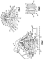
Figure 1 is a partial cross-sectional view of a front portion of a gas turbine engine illustrating a turbo fan, epicyclic gear train and a compressor section. -
Figure 2 is an enlarged cross-sectional view of the epicyclic gear train shown inFigure 1 . -
Figure 3 is an enlarged cross-sectional view of an example ring gear similar to the arrangement shown inFigure 2 . -
Figure 4 is a view of the ring gear shown inFigure 3 viewed in a direction that faces the teeth of the ring gear inFigure 3 . -
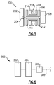
Figure 5 shows another embodiment. -
Figure 6 shows yet another embodiment. - A portion of a
gas turbine engine 10 is shown schematically inFigure 1 . Theturbine engine 10 includes afixed housing 12 that is constructed from numerous pieces secured to one another. Acompressor section 14 havingcompressor hubs 16 with blades are driven by aturbine shaft 25 about an axis A. Aturbo fan 18 is supported on aturbo fan shaft 20 that is driven by acompressor shaft 24, which supports thecompressor hubs 16, through anepicyclic gear train 22. - In the example arrangement shown, the
epicyclic gear train 22 is a star gear train. Referring toFigure 2 , theepicyclic gear train 22 includes a sun gear 30 that is connected to thecompressor shaft 24, which provides rotational input, by a splined connection. Acarrier 26 is fixed to thehousing 12 by atorque frame 28 using fingers (not shown) known in the art. Thecarrier 26 supportsstar gears 32 usingjournal bearings 34 that are coupled to the sun gear 30 by meshed interfaces between the teeth of sun andstar gears 30, 32.Multiple star gears 32 are arranged circumferentially about the sun gear 30.Retainers 36 retain thejournal bearings 34 to thecarrier 26. Aring gear 38 surrounds thecarrier 26 and is coupled to thestar gears 32 by meshed interfaces. Thering gear 38, which provides rotational output, is secured to theturbo fan shaft 20 by circumferentially arranged fastening elements, which are described in more detail below. - As shown, each of the
star gears 32 is supported on one of thejournal bearings 34. Each journal bearing 34 has an internalcentral cavity 34a that extends betweenaxial ends central cavity 34a is axially blind in that theaxial end 35a is closed. At least onepassage 37 extends from the internalcentral cavity 34a to aperipheral journal surface 39. In the example, the at least onepassage 37 includes afirst passage 37a and asecond passage 37b that is axially spaced form thefirst passage 37a. As shown, the first andsecond passages central cavity 34a. - In operation, lubricant is provided to the internal
central cavity 34a. The lubricant flows through the internalcentral cavity 34a and then outwardly through the at least onepassage 37 to theperipheral journal surface 39. The arrangement of the internalcentral cavity 34a and at least onepassage 37 thereby serves to cool and lubricate thejournal bearing 32. - The
gas turbine engine 10 is a high-bypass geared architecture aircraft engine. In one disclosed, non-limiting embodiment, theengine 10 has a bypass ratio that is greater than about six (6:1) to ten (10:1), theepicyclic gear train 22 is a planetary gear system or other gear system with a gear reduction ratio of greater than about 2.3 or greater than about 2.5, and a low pressure turbine of theengine 10 has a pressure ratio that is greater than about 5. In one disclosed embodiment, theengine 10 bypass ratio is greater than about ten (10:1) or greater than about 10.5:1, theturbofan 18 diameter is significantly larger than that of the low pressure compressor of thecompressor section 14, and the low pressure turbine has a pressure ratio that is greater than about five (5:1). In one example, theepicyclic gear train 22 has a gear reduction ratio of greater than about 2.3:1 or greater than about 2.5:1. It should be understood, however, that the above parameters are only exemplary of one embodiment of a geared architecture engine. - A significant amount of thrust is provided by a bypass flow B due to the high bypass ratio. The
fan 18 of theengine 10 is designed for a particular flight condition -- typically cruise at about 0.8M and about 35,000 feet (10,668 m). The flight condition of 0.8 M and 35,000 ft (10,668 m), with the engine at its best fuel consumption - also known as "bucket cruise TSFC" - is the industry standard parameter of lbm of fuel being burned divided by lbf of thrust the engine produces at that minimum point. "Low fan pressure ratio" is the pressure ratio across the fan blade alone. The low fan pressure ratio as disclosed herein according to one non-limiting embodiment is less than about 1.45. "Low corrected fan tip speed" is the actual fan tip speed in ft/sec divided by an industry standard temperature correction of [(Tambient °R) / 518.7) 0.5] (where °R = K x 9/5). The "Low corrected fan tip speed" as disclosed herein according to one non-limiting embodiment is less than about 1150 ft / second (350.5 m/s). - Referring to
Figures 3 and 4 , thering gear 38 is a two-piece construction having first andsecond portions second portions radial interface 45. Atrough 41 separates oppositely angled teeth 43 (best shown inFigure 4 ) on each of the first andsecond portions teeth 43 forces the first andsecond portions radial interface 45. The back side of the first andsecond portions circumferential surface 47 that, coupled with a change in thickness, provides structural rigidity and resistance to overturning moments. The first andsecond portions second portions recesses 44 that form an internalannular cavity 46. - The first and
second portions flanges 51 that extend radially outward away from theteeth 43. Theturbo fan shaft 20 includes a radially outwardly extendingflange 70 that is secured to theflanges 51 by circumferentially arrangedbolts 52 andnuts 54, which axially constrain and affix theturbo fan shaft 20 andring gear 38 relative to one another. Thus, the spline ring is eliminated, which also reduces heat generated from windage and churning that resulted from the sharp edges and surface area of the splines. Theturbo fan shaft 20 andring gear 38 can be rotationally balanced with one another since radial movement resulting from the use of splines is eliminated. Anoil baffle 68 is also secured to theflanges -
Seals 56 having knife edges 58 are secured to theflanges second portions grooves 48 at theradial interface 45 that form ahole 50, which expels oil through thering gear 38 to agutter 60 that is secured to thecarrier 26 with fasteners 61 (Figure 2 ). The direct radial flow path provided by thegrooves 48 reduces windage and churning by avoiding the axial flow path change that existed with splines. That is, the oil had to flow radially and then axially to exit through the spline interface. Thegutter 60 is constructed from a soft material such as aluminum so that the knife edges 58, which are constructed from steel, can cut into the aluminum if they interfere. Referring toFigure 3 , theseals 56 also includeoil return passages 62 provided by first andsecond slots 64 in theseals 56, which permit oil on either side of thering gear 38 to drain into thegutter 60. In the example shown inFigure 2 , the first andsecond slots flange 70 andoil baffle 68, respectively. -
Figure 5 shows anembodiment 200, wherein there is afan drive turbine 208 driving a shaft 206 to in turn drive afan rotor 202. Agear reduction 204 may be positioned between thefan drive turbine 208 and thefan rotor 202. Thisgear reduction 204 may be structured and operate like theepicyclic gear train 22 disclosed above. Acompressor rotor 210 is driven by anintermediate pressure turbine 212, and a second stage compressor rotor 214 is driven by a turbine rotor 216. A combustion section 218 is positioned intermediate the compressor rotor 214 and the turbine section 216. All other features of the engine of thisembodiment 200 may be as discussed above. -
Figure 6 shows yet anotherembodiment 300 wherein afan rotor 302 and afirst stage compressor 304 rotate at a common speed. The gear reduction 306 (which may be structured and operate like theepicyclic gear train 22 disclosed above) is intermediate thecompressor rotor 304 and ashaft 308 which is driven by a low pressure turbine section, such as the fan drive turbine discussed above. All other features of the engine of thisembodiment 300 may be as discussed above. - Although embodiments of this invention have been disclosed, a worker of ordinary skill in this art would recognize that certain modifications would come within the scope of this invention. For that reason, the following claims should be studied to determine the true scope and content of this invention.
Claims (14)
- A turbine engine (10) comprising:a fan shaft (20);at least one tapered bearing mounted on the fan shaft (20), the fan shaft (20) including at least one passage extending in a direction having at least a radial component, and adjacent the at least one tapered bearing;a fan (18) mounted for rotation on the tapered bearing;an epicyclic gear train (22) coupled to drive the fan (18), the epicyclic gear train (22) including a carrier (26) supporting intermediate gears (32) that mesh with a sun gear (30), and a ring gear (38) surrounding and meshing with the intermediate gears (32), each of the intermediate gears (32) being supported on a respective journal bearing (34), wherein the epicyclic gear train (22) defines a gear reduction ratio of greater than or equal to about 2.3; anda turbine section coupled to drive the fan (18) through the epicyclic gear train (22), the turbine section having a fan drive turbine (208) that includes a pressure ratio that is greater than 5, the fan (18) includes a pressure ratio that is less than 1.45, and the fan (18) has a bypass ratio of greater than ten.
- The turbine engine (10) as recited in claim 1, wherein the fan shaft (20) is coupled to the ring gear (38).
- The turbine engine (10) as recited in claim 1 or 2, wherein the at least one tapered bearing includes a first tapered bearing and the at least one passage includes a first passage and a second passage, the first passage being located at an axially forward side of the first tapered bearing and the second passage being located at an axially aft side of the first tapered bearing.
- The turbine engine (10) as recited in any preceding claim, wherein the fan shaft (20) includes, on a radially inner surface, at least one well extending between axial sides and a radial side, and the at least one passage opens at the radial side.
- The turbine engine (10) as recited in any of claims 1 to 3, wherein the fan shaft (20) includes, on a radially inner surface, a plurality of wells each extending between axial side walls and a radial side wall, and the at least one passage includes a plurality of passages that open at respective ones of the radial side walls of the plurality of wells.
- The turbine engine (10) as recited in claim 5, wherein two wells of the plurality of wells are axially adjacent such that the two wells share a common axial side wall.
- The turbine engine (10) as recited in claim 5 or 6, wherein the axial side walls are gradually sloped.
- The turbine engine (10) as recited in any preceding claim, wherein the epicyclic gear train (22) has a gear reduction ratio of greater than or equal to 2.3.
- The turbine engine (10) as recited in any of claims 1 to 7, wherein the epicyclic gear train (22) has a gear reduction ratio of greater than or equal to about 2.5.
- The turbine engine (10) as recited in any of claims 1 to 7, wherein the epicyclic gear train (22) has a gear reduction ratio of greater than or equal to 2.5.
- The turbine engine (10) as recited in any preceding claim, wherein the fan (18) defines a bypass ratio of greater than about 10.5:1 with regard to a bypass airflow and a core airflow.
- The turbine engine (10) as recited in any preceding claim, wherein there are three turbines (208, 212, 216), with said fan drive turbine (208) being a lowest pressure turbine, and there being a high pressure turbine (216) and an intermediate pressure turbine (212), with said high pressure turbine (216) and said intermediate pressure turbine (212) each driving a compressor rotor (210, 214).
- The turbine engine (10) as recited in any of claims 1 to 11, wherein the epicyclic gear train (22) is intermediate a compressor rotor (304) and a shaft (308) which is driven by the fan drive turbine (208).
- The turbine engine (10) as recited in claim 13, wherein the engine (10) is configured such that the fan (18) rotates at the same speed as the compressor rotor (34).
Applications Claiming Priority (1)
| Application Number | Priority Date | Filing Date | Title |
|---|---|---|---|
| US14/824,351 US9976437B2 (en) | 2006-08-15 | 2015-08-12 | Epicyclic gear train |
Publications (1)
| Publication Number | Publication Date |
|---|---|
| EP3130766A1 true EP3130766A1 (en) | 2017-02-15 |
Family
ID=56851386
Family Applications (1)
| Application Number | Title | Priority Date | Filing Date |
|---|---|---|---|
| EP16183877.6A Withdrawn EP3130766A1 (en) | 2015-08-12 | 2016-08-11 | Epicyclic gear train |
Country Status (3)
| Country | Link |
|---|---|
| EP (1) | EP3130766A1 (en) |
| JP (1) | JP2017036726A (en) |
| CA (1) | CA2936576C (en) |
Cited By (1)
| Publication number | Priority date | Publication date | Assignee | Title |
|---|---|---|---|---|
| CN114151206A (en) * | 2020-09-07 | 2022-03-08 | 中国航发商用航空发动机有限责任公司 | Fan driving structure and assembling method thereof |
Citations (3)
| Publication number | Priority date | Publication date | Assignee | Title |
|---|---|---|---|---|
| US20120275904A1 (en) * | 2006-08-15 | 2012-11-01 | Mccune Michael E | Gas turbine engine lubrication |
| EP2610527A2 (en) * | 2011-12-30 | 2013-07-03 | United Technologies Corporation | Epicyclic gear train and turbine engine |
| US20140154054A1 (en) * | 2006-07-05 | 2014-06-05 | United Technologies Corporation | Oil baffle for gas turbine fan drive gear system |
Family Cites Families (3)
| Publication number | Priority date | Publication date | Assignee | Title |
|---|---|---|---|---|
| BR102012028940A2 (en) * | 2011-12-30 | 2015-10-06 | United Technologies Corp | gas turbine engine |
| US20130318998A1 (en) * | 2012-05-31 | 2013-12-05 | Frederick M. Schwarz | Geared turbofan with three turbines with high speed fan drive turbine |
| CA2879244C (en) * | 2014-01-21 | 2018-04-03 | United Technologies Corporation | Low noise compressor rotor for geared turbofan engine |
-
2016
- 2016-07-18 CA CA2936576A patent/CA2936576C/en active Active
- 2016-07-27 JP JP2016146848A patent/JP2017036726A/en active Pending
- 2016-08-11 EP EP16183877.6A patent/EP3130766A1/en not_active Withdrawn
Patent Citations (3)
| Publication number | Priority date | Publication date | Assignee | Title |
|---|---|---|---|---|
| US20140154054A1 (en) * | 2006-07-05 | 2014-06-05 | United Technologies Corporation | Oil baffle for gas turbine fan drive gear system |
| US20120275904A1 (en) * | 2006-08-15 | 2012-11-01 | Mccune Michael E | Gas turbine engine lubrication |
| EP2610527A2 (en) * | 2011-12-30 | 2013-07-03 | United Technologies Corporation | Epicyclic gear train and turbine engine |
Cited By (2)
| Publication number | Priority date | Publication date | Assignee | Title |
|---|---|---|---|---|
| CN114151206A (en) * | 2020-09-07 | 2022-03-08 | 中国航发商用航空发动机有限责任公司 | Fan driving structure and assembling method thereof |
| CN114151206B (en) * | 2020-09-07 | 2023-11-14 | 中国航发商用航空发动机有限责任公司 | Fan driving structure and assembling method thereof |
Also Published As
| Publication number | Publication date |
|---|---|
| BR102016018333A2 (en) | 2017-02-14 |
| CA2936576A1 (en) | 2017-02-12 |
| CA2936576C (en) | 2018-05-01 |
| JP2017036726A (en) | 2017-02-16 |
Similar Documents
| Publication | Publication Date | Title |
|---|---|---|
| US12084978B2 (en) | Epicyclic gear train | |
| US8708863B2 (en) | Epicyclic gear train | |
| US8939864B2 (en) | Gas turbine engine lubrication | |
| US10196989B2 (en) | Gas turbine engine gear train | |
| EP1890054B1 (en) | Ring gear mounting arrangement with oil scavenge scheme | |
| US8894538B2 (en) | Gas turbine engine with geared architecture | |
| EP2610463B1 (en) | Gas turbine engine gear train | |
| US20190113003A1 (en) | Gas turbine engine with geared architecture | |
| EP2610464B1 (en) | Gas Turbine engine | |
| EP3628894A1 (en) | Gear apparatus and turbine engine | |
| CA2936576C (en) | Epicyclic gear train | |
| EP3825534A1 (en) | Gas turbine engine with geared architecture | |
| EP3112648A1 (en) | Gas turbine engine with geared architecture |
Legal Events
| Date | Code | Title | Description |
|---|---|---|---|
| PUAI | Public reference made under article 153(3) epc to a published international application that has entered the european phase |
Free format text: ORIGINAL CODE: 0009012 |
|
| STAA | Information on the status of an ep patent application or granted ep patent |
Free format text: STATUS: THE APPLICATION HAS BEEN PUBLISHED |
|
| AK | Designated contracting states |
Kind code of ref document: A1 Designated state(s): AL AT BE BG CH CY CZ DE DK EE ES FI FR GB GR HR HU IE IS IT LI LT LU LV MC MK MT NL NO PL PT RO RS SE SI SK SM TR |
|
| AX | Request for extension of the european patent |
Extension state: BA ME |
|
| STAA | Information on the status of an ep patent application or granted ep patent |
Free format text: STATUS: REQUEST FOR EXAMINATION WAS MADE |
|
| 17P | Request for examination filed |
Effective date: 20170808 |
|
| RBV | Designated contracting states (corrected) |
Designated state(s): AL AT BE BG CH CY CZ DE DK EE ES FI FR GB GR HR HU IE IS IT LI LT LU LV MC MK MT NL NO PL PT RO RS SE SI SK SM TR |
|
| STAA | Information on the status of an ep patent application or granted ep patent |
Free format text: STATUS: EXAMINATION IS IN PROGRESS |
|
| 17Q | First examination report despatched |
Effective date: 20200406 |
|
| RAP1 | Party data changed (applicant data changed or rights of an application transferred) |
Owner name: RAYTHEON TECHNOLOGIES CORPORATION |
|
| STAA | Information on the status of an ep patent application or granted ep patent |
Free format text: STATUS: THE APPLICATION HAS BEEN WITHDRAWN |
|
| 18W | Application withdrawn |
Effective date: 20210614 |