EP3130753A1 - Gas turbine unit with adaptive pre-swirler - Google Patents
Gas turbine unit with adaptive pre-swirler Download PDFInfo
- Publication number
- EP3130753A1 EP3130753A1 EP16184087.1A EP16184087A EP3130753A1 EP 3130753 A1 EP3130753 A1 EP 3130753A1 EP 16184087 A EP16184087 A EP 16184087A EP 3130753 A1 EP3130753 A1 EP 3130753A1
- Authority
- EP
- European Patent Office
- Prior art keywords
- curve
- cooling airflow
- gas turbine
- turbine unit
- speed
- Prior art date
- Legal status (The legal status is an assumption and is not a legal conclusion. Google has not performed a legal analysis and makes no representation as to the accuracy of the status listed.)
- Granted
Links
Images



Classifications
-
- F—MECHANICAL ENGINEERING; LIGHTING; HEATING; WEAPONS; BLASTING
- F01—MACHINES OR ENGINES IN GENERAL; ENGINE PLANTS IN GENERAL; STEAM ENGINES
- F01D—NON-POSITIVE DISPLACEMENT MACHINES OR ENGINES, e.g. STEAM TURBINES
- F01D5/00—Blades; Blade-carrying members; Heating, heat-insulating, cooling or antivibration means on the blades or the members
- F01D5/02—Blade-carrying members, e.g. rotors
- F01D5/08—Heating, heat-insulating or cooling means
- F01D5/081—Cooling fluid being directed on the side of the rotor disc or at the roots of the blades
-
- F—MECHANICAL ENGINEERING; LIGHTING; HEATING; WEAPONS; BLASTING
- F02—COMBUSTION ENGINES; HOT-GAS OR COMBUSTION-PRODUCT ENGINE PLANTS
- F02C—GAS-TURBINE PLANTS; AIR INTAKES FOR JET-PROPULSION PLANTS; CONTROLLING FUEL SUPPLY IN AIR-BREATHING JET-PROPULSION PLANTS
- F02C7/00—Features, components parts, details or accessories, not provided for in, or of interest apart form groups F02C1/00 - F02C6/00; Air intakes for jet-propulsion plants
-
- F—MECHANICAL ENGINEERING; LIGHTING; HEATING; WEAPONS; BLASTING
- F02—COMBUSTION ENGINES; HOT-GAS OR COMBUSTION-PRODUCT ENGINE PLANTS
- F02C—GAS-TURBINE PLANTS; AIR INTAKES FOR JET-PROPULSION PLANTS; CONTROLLING FUEL SUPPLY IN AIR-BREATHING JET-PROPULSION PLANTS
- F02C7/00—Features, components parts, details or accessories, not provided for in, or of interest apart form groups F02C1/00 - F02C6/00; Air intakes for jet-propulsion plants
- F02C7/12—Cooling of plants
- F02C7/16—Cooling of plants characterised by cooling medium
- F02C7/18—Cooling of plants characterised by cooling medium the medium being gaseous, e.g. air
-
- F—MECHANICAL ENGINEERING; LIGHTING; HEATING; WEAPONS; BLASTING
- F02—COMBUSTION ENGINES; HOT-GAS OR COMBUSTION-PRODUCT ENGINE PLANTS
- F02C—GAS-TURBINE PLANTS; AIR INTAKES FOR JET-PROPULSION PLANTS; CONTROLLING FUEL SUPPLY IN AIR-BREATHING JET-PROPULSION PLANTS
- F02C9/00—Controlling gas-turbine plants; Controlling fuel supply in air- breathing jet-propulsion plants
- F02C9/16—Control of working fluid flow
- F02C9/18—Control of working fluid flow by bleeding, bypassing or acting on variable working fluid interconnections between turbines or compressors or their stages
-
- F—MECHANICAL ENGINEERING; LIGHTING; HEATING; WEAPONS; BLASTING
- F05—INDEXING SCHEMES RELATING TO ENGINES OR PUMPS IN VARIOUS SUBCLASSES OF CLASSES F01-F04
- F05D—INDEXING SCHEME FOR ASPECTS RELATING TO NON-POSITIVE-DISPLACEMENT MACHINES OR ENGINES, GAS-TURBINES OR JET-PROPULSION PLANTS
- F05D2260/00—Function
- F05D2260/14—Preswirling
Definitions
- the present invention relates to a gas turbine unit with adaptive pre-swirler.
- the blades and other turbine expansion stage components must be cooled during use, as otherwise they would be damaged in a short time by the extremely high temperature of the working fluid (hot gases expelled from the combustion chamber).
- Fresh air is usually used for cooling, drawn from the compressor and supplied through a cooling circuit (also called a secondary air circuit) defined by fluid passages obtained partly between the rotor and stator and partly inside the blades. The cooling air then flows out through holes on the surface of the blades, and is introduced into the main flow of working fluid.
- Cooling is necessary for both the rotor and stator blades.
- the implementation of efficient cooling systems presents more significant problems, because the cooling air passes between fixed and rotating components.
- Possible reductions in pressure in the circuit supplying the cooling air may even lead to increases in temperature, reducing the efficiency of the cooling system.
- an inefficient cooling system may lead to a premature deterioration of the turbine components or even, in some cases, catastrophic damage.
- a rotation about the main axis of the machine must be imparted to the cooling airflow so that the tangential speed component of the cooling airflow remains proportionate to the rotor speed.
- This aim is generally achieved by using a swirler or pre-swirler along the cooling circuit to deviate the airflow in the desired way.
- the pre-swirlers are designed to achieve an optimum swirl ratio in certain working conditions, in which the gas turbine operates for most of the time. In these operating conditions, the airflow speed is predictable and constant, and therefore the rotation to be imparted to the airflow so that it is proportionate to the rotor speed can also be determined.
- the operating conditions are not always the same.
- the power supplied to the distribution networks must be proportionate to user demand and the projected use as defined by local operators, with significant differences in daily cycles (in particular, there are generally periods of operation at nominal power and periods of operation at the lowest possible capacity).
- the individual plants are also required to take part in monitoring network frequency, and therefore contributions may be requested at unforeseeable times.
- the speed module of the airflow in the pre-swirler also changes according to the difference in required output, while its direction essentially remains constant, as does the speed of the rotor.
- the reduction in airflow speed leads to a corresponding reduction in the tangential component, which is therefore no longer proportionate to the rotor speed according to the optimum swirl ratio.
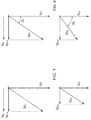
- FIG. 1 The consequence when using pre-swirlers of the type known in the prior art is illustrated by way of example in figure 1 , where the vector V R represents the tangential speed of the rotor at a distance from the main axis that corresponds to the pre-swirler outlet; the vectors V I1 , V I2 represent the speed of the cooling airflow at the pre-swirler inlet in a first operating condition (for example at nominal power) and in a second operating condition (for example at minimum capacity), respectively; and the vectors V O1 , V O2 represent the speed of the cooling airflow at the pre-swirler outlet in the first operating condition and in the second operating condition, respectively.
- the vector V R represents the tangential speed of the rotor at a distance from the main axis that corresponds to the pre-swirler outlet
- the vectors V I1 , V I2 represent the speed of the cooling airflow at the pre-swirler inlet in a first operating condition (for example at nominal power) and in a
- the vectors V O1 , V O2 necessarily have different tangential components V O1T , V O2T in the direction of the vector V R . It is therefore evident that the ratio between the tangential speed component of the airflow from the pre-swirler and the tangential speed of the rotor only gives the optimum swirl ratio, for example 1, in one operating condition. Apart from this specific condition, for example if there is a reduction in the speed of the airflow conveyed through the pre-swirler (as occurs with the vector V I2 ), the ratio between the tangential speed of the airflow from the pre-swirler and the tangential speed of the rotor moves away from the optimum value.
- the aim of the present invention is therefore to provide a gas turbine that can overcome or at least reduce the limits described above, and that, in particular, makes it possible to adapt the tangential speed component of the cooling airflow to the speed of the rotor in a plurality of operating conditions.
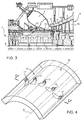
- FIG 2 a gas turbine unit 1 for an electrical energy production system is illustrated as a whole.
- the gas turbine unit 1 comprises a stator 2, a rotor 3, which extends along a main axis A, and a combustion chamber 6.
- the stator 2 defines a case for accommodating the rotor 3 rotatably about the main axis A. Furthermore, the stator 2 and the rotor 3 form a compressor 4 and a turbine 5 with said stator 3.
- the rotor 3 is equipped with a plurality of compressor rotor blades 7 and turbine rotor blades 8, arranged in annular arrays, which are positioned successively along the axis A of the rotor 3.
- Arrays of compressor stator vanes 9 and turbine stator vanes 10 are attached to the case 2, between the compressor rotor blades 7 and the turbine rotor blades 8, respectively.
- the compressor 4 and the turbine 5 are separated by a rotating member called the central hollow shaft 11.
- the combustion chamber 6 is of the toroidal type and is positioned about the central hollow shaft 11, between the compressor 4 and the turbine 5.
- a cooling circuit 12 extends partly in the stator 2 and partly in the rotor 3 to allow a cooling airflow AF to be supplied from the compressor 4 to the turbine 5, in order to avoid overheating of the turbine rotor blades 8 and of the turbine stator vanes 10.
- the cooling circuit 12 comprises a pre-swirler 15, which is configured to impart a rotation about the axis A to the cooling airflow AF conveyed from the compressor 4.
- the pre-swirler 15 is incorporated in a portion of the stator 2 called the shaft cover 16 and essentially defined by a cylindrical wall located around the central hollow shaft 11.
- the pre-swirler 15 fluidically couples a first portion of the cooling circuit 12, immediately downstream of the compressor 4, and a second portion of the cooling circuit 12, which extends in an annular cavity between the shaft cover 16 (which is fixed as it is part of the stator 2) and the central hollow shaft 11 (which rotates as it is part of the rotor 3).
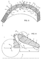
- the pre-swirler 15 comprises a plurality of flow channels 17 arranged about the main axis A.
- the flow channels 17 are through holes in the shaft cover 16 and extend along respective curved paths about the main axis A.
- the shape of the flow channels 17 allows to modify a tangential speed component of the cooling airflow AF in accordance with the angular speed of the rotor 3, which is substantially constant.
- a speed vector applied at a given point in particular with regard to the cooling airflow AF, will be understood as having an axial component, parallel to the main axis A, a radial component, perpendicular to the main axis A, and a tangential component, positioned tangentially to a circumference that is concentric to the main axis A and with a radius equal to the distance from the main axis A of the base or starting point of the speed vector.
- each airflow channel 17 comprises an inlet portion 17a, an outlet portion 17b and a joining section 17c between the inlet portion 17a and the outlet portion 17b.
- a median line on the flow channel 17 extends substantially in a plane, for example (though not necessarily) a plane perpendicular to the main axis A.
- the inlet portion 17a may be radial.
- the outlet portion 17b has a width such as to allow the cooling airflow AF to leave the pre-swirler 15 at an outlet speed V O that forms an outlet angle ⁇ ( figure 5 ) variable within a range, for example comprised between 40° and 89°, with respect to the direction of the inlet speed V I in the inlet portion 17a.
- the ratio between a passage section S 1 of the inlet portion 17a and a passage section S 2 of the outlet portion 17b is comprised between 0.3 and 3.
- the joining section 17c defines a first curve and is configured to deviate the cooling airflow AF by Coanda effect, by a variable angle according to the absolute value of the inlet speed V I .
- the joining section 17c is delimitated by a first side wall 17d inside the first curve, and by a second side wall 17e opposite the first side wall 17d and outside the first curve.
- the first side wall 17d may have a constant curvature radius.
- the ratio between the equivalent diameter of the passage section S 1 of the inlet portion 17a and the curvature radius R 1 of the first side wall 17d may be comprised between 0.02 and 6.
- the "equivalent diameter" of a given channel is understood to mean the diameter of a channel with a circular cross section with an area equivalent to the area of the passage section of the given channel.
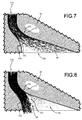
- the cooling airflow AF tends to adhere to the first internal side wall 17d of the first curve of the flow channel 17 and is therefore deviated to a detachment point, as shown in figure 7 (at low inlet speeds, the detachment point may correspond to the outlet edge of the flow channel 17). With respect to the path in the flow channel 17, the detachment point from the internal wall 17d moves further back as the absolute speed value increases. The cooling airflow AF is therefore deflected to a greater extent, and is subjected to a larger rotation when the inlet speed V I has a lower absolute value, and vice versa.
- the second side wall 17e defines a second curve, which, when lapped against by the cooling airflow AF, imparts an opposite rotation to that imparted by the first curve.
- opposite rotation' or 'rotation in the opposite direction' are taken to mean that if in a given system the first curve imparts a clockwise rotation to the cooling airflow AF, the second curve imparts an anticlockwise rotation in the same given system (and vice versa).
- the second curve gives the second side wall 17e a divergent profile with respect to the first side wall 17d on a plane perpendicular to the main axis A and which contains the median line of the flow channel 17.
- the shape of the second side part 17e makes an additional contribution with respect to that made by the first side wall 17d, and allows the range of outlet angles ⁇ of the outlet speed V O that can be obtained with the pre-swirler 15 to be increased further.
- the second curve is designed to be completely lapped against by the cooling airflow AF only when the absolute speed value exceeds a critical threshold within the accepted range ( figure 8 ).
- This critical threshold is carefully defined according to the operating conditions of the gas turbine unit and may correspond to the speed of the cooling airflow AF under full load conditions. For absolute speed values below the threshold, the cooling airflow AF is deviated by the second side wall 17e in order not to reach the second curve ( figure 7 ). In these cases, the second curve is practically irrelevant.
- the effect of the second curve in the second side wall 17e becomes appreciable. Practically speaking, the second curve imparts a rotation opposite to that imparted by the first curve on the cooling airflow AF, further decreasing the overall rotation provided by the flow channel 17.
- the efficiency of the cooling circuit 12 is therefore at an optimum level in all operating conditions and the risk of changes in the speed of the cooling airflow AF causing reductions in pressure and rises in temperature, which can affect the overall efficiency of the machine and in the long term its entire structure, is avoided or at least significantly reduced.
- the result is achieved by exploiting the Coanda effect. Due to its shape, the pre-swirler 15 is thus able to adapt the tangential speed component of the cooling airflow AF according to the operating conditions without the need for adjustments and moving parts.
- the first curve makes it possible to achieve high deflections at a low speed.
- the second curve reduces the rotation of the cooling airflow AF at high speed, essentially making it possible to widen the range of accepted speeds.
- a pre-swirler 115 obtained in a shaft cover 116 of a gas turbine unit (not entirely illustrated) comprises a plurality of tangential vanes 118 that define identical flow channels 117 about the main axis, indicated here with A'.
- the plane representation of the pre-swirler 115 is illustrated in figure 11 .
- each vane 118 has a first face 188a and a second face 118b opposite one another.
- Each channel 117 is therefore defined by the first face 118a of a vane 118 and the second face 118b of an adjacent vane 118.
- the flow channel 117 is curved and comprises an inlet portion 117a, an outlet portion 117b and a joining section 117c between the inlet portion 117a and the outlet portion 117b.
- the joining section 117c forms a first curve, delimited on an inner side by the first face 118a of one respective vane 118 and on an outer side by the second face 118b of the other respective vane 118.
- the first curve of the joining section 117c is configured to deviate the cooling airflow AF' about the main axis A' by Coanda effect by a variable angle according to the absolute value of the inlet speed V I '.
- the outlet portion 117b forms a second curve, that, again by Coanda effect, imparts an opposite rotation to the cooling airflow AF' when the absolute speed value comes close to a critical threshold.
- the second curve is defined by an end part of the second face 118b of the vane 118 that delimits the flow channel 117.
- the airflow channel 117 may have the parameters already defined with reference to figures 3-9 , in particular:
- a gas turbine unit (only partially illustrated) comprises a cooling circuit 212 which extends partially through turbine stator vanes 201 and turbine rotor blades 208.
- the cooling circuit comprises, at least in a turbine stage, a ring 213 having a U-shaped cross section and defining an annular chamber 214.
- the ring 213 joins the ends of the turbine stator vanes 210 and, apart from having a structural function, also acts as a recipient to convey the cooling airflow towards the portion of the cooling circuit that extends inside the turbine rotor blades 208.
- the ring 213 is equipped with a pre-swirler 215 that comprises a plurality of flow channels 217.
- the flow channels 217 are defined by holes that join the chamber 214 with the external part of the ring 213 and extend diagonally in relation to the main axis A".
- the flow channels 217 are shaped to impart a rotation about the main axis A" by Coanda effect according to the cooling airflow speed, essentially as described above.
- the flow channels 217 form a first curve, with an internal wall that imparts the highest rotation at low speeds of the cooling airflow; and a second curve that imparts a rotation opposite to that imparted by the first curve when the speed of the cooling airflow approaches the critical threshold.
Landscapes
- Engineering & Computer Science (AREA)
- Chemical & Material Sciences (AREA)
- Combustion & Propulsion (AREA)
- Mechanical Engineering (AREA)
- General Engineering & Computer Science (AREA)
- Physics & Mathematics (AREA)
- Fluid Mechanics (AREA)
- Turbine Rotor Nozzle Sealing (AREA)
Abstract
Description
- The present invention relates to a gas turbine unit with adaptive pre-swirler.
- As is known, in gas turbine systems, the blades and other turbine expansion stage components must be cooled during use, as otherwise they would be damaged in a short time by the extremely high temperature of the working fluid (hot gases expelled from the combustion chamber). Fresh air is usually used for cooling, drawn from the compressor and supplied through a cooling circuit (also called a secondary air circuit) defined by fluid passages obtained partly between the rotor and stator and partly inside the blades. The cooling air then flows out through holes on the surface of the blades, and is introduced into the main flow of working fluid.
- Cooling is necessary for both the rotor and stator blades. For the former, however, the implementation of efficient cooling systems presents more significant problems, because the cooling air passes between fixed and rotating components. Possible reductions in pressure in the circuit supplying the cooling air may even lead to increases in temperature, reducing the efficiency of the cooling system. Apart from a possible decline in machine output, an inefficient cooling system may lead to a premature deterioration of the turbine components or even, in some cases, catastrophic damage. In order to avoid such inconveniences, a rotation about the main axis of the machine must be imparted to the cooling airflow so that the tangential speed component of the cooling airflow remains proportionate to the rotor speed. This means that there must be a determined ratio, also called a swirl ratio, between the tangential speed component of the cooling airflow from the stator and the tangential speed of the rotor at the distance from the main axis at which the cooling airflow passes between the fixed and rotating component.
- This aim is generally achieved by using a swirler or pre-swirler along the cooling circuit to deviate the airflow in the desired way.
- However, the solutions known in the prior art have significant limitations. The pre-swirlers are designed to achieve an optimum swirl ratio in certain working conditions, in which the gas turbine operates for most of the time. In these operating conditions, the airflow speed is predictable and constant, and therefore the rotation to be imparted to the airflow so that it is proportionate to the rotor speed can also be determined. However, the operating conditions are not always the same. In modern systems used to produce electricity, for example, the power supplied to the distribution networks must be proportionate to user demand and the projected use as defined by local operators, with significant differences in daily cycles (in particular, there are generally periods of operation at nominal power and periods of operation at the lowest possible capacity). The individual plants are also required to take part in monitoring network frequency, and therefore contributions may be requested at unforeseeable times. When the power supplied changes, the speed module of the airflow in the pre-swirler also changes according to the difference in required output, while its direction essentially remains constant, as does the speed of the rotor. The reduction in airflow speed leads to a corresponding reduction in the tangential component, which is therefore no longer proportionate to the rotor speed according to the optimum swirl ratio. The consequence when using pre-swirlers of the type known in the prior art is illustrated by way of example in
figure 1 , where the vector VR represents the tangential speed of the rotor at a distance from the main axis that corresponds to the pre-swirler outlet; the vectors VI1, VI2 represent the speed of the cooling airflow at the pre-swirler inlet in a first operating condition (for example at nominal power) and in a second operating condition (for example at minimum capacity), respectively; and the vectors VO1, VO2 represent the speed of the cooling airflow at the pre-swirler outlet in the first operating condition and in the second operating condition, respectively. - The vectors VO1, VO2 necessarily have different tangential components VO1T, VO2T in the direction of the vector VR. It is therefore evident that the ratio between the tangential speed component of the airflow from the pre-swirler and the tangential speed of the rotor only gives the optimum swirl ratio, for example 1, in one operating condition. Apart from this specific condition, for example if there is a reduction in the speed of the airflow conveyed through the pre-swirler (as occurs with the vector VI2), the ratio between the tangential speed of the airflow from the pre-swirler and the tangential speed of the rotor moves away from the optimum value.
- The aim of the present invention is therefore to provide a gas turbine that can overcome or at least reduce the limits described above, and that, in particular, makes it possible to adapt the tangential speed component of the cooling airflow to the speed of the rotor in a plurality of operating conditions.
- According to the present invention, there is provided a gas turbine unit as defined in claim 1.
- The present invention will now be described with reference to the drawings attached hereto, illustrating some non-limiting embodiments thereof, in which:
-
figure 1 is a diagram illustrating quantities referring to a gas turbine unit known in the prior art; -
figure 2 is a side view, cut along an axial, longitudinal plane, of a gas turbine unit according to an embodiment of the present invention; -
figure 3 displays an enlarged portion of the gas turbine unit infigure 2 ; -
figure 4 is a perspective view of a portion of a component of the gas turbine infigure 1 ; -
figure 5 is a perspective view of the component infigure 4 , in a sectional view along the plane V-V infigure 4 ; -
figure 6 is a schematic view of a part of the component infigure 4 ; -
figure 7 is a schematic view of the same part of the component infigure 4 , in a first operational configuration; -
figure 8 is a schematic view of the same part of the component infigure 4 , in a second operational configuration; -
figure 9 is a diagram illustrating quantities referring to the gas turbine unit infigure 2 ; -
figure 10 is a perspective view of a portion of a component of a gas turbine unit, according to an alternative embodiment of the present invention; -
figure 11 is a plane representation of the component infigure 10 ; and -
figure 12 is a side view, cut along an axial, longitudinal plane, of a portion of a component of a gas turbine unit according to another alternative embodiment of the present invention. - In
figure 2 , a gas turbine unit 1 for an electrical energy production system is illustrated as a whole. - The gas turbine unit 1 comprises a
stator 2, a rotor 3, which extends along a main axis A, and acombustion chamber 6. - The
stator 2 defines a case for accommodating the rotor 3 rotatably about the main axis A. Furthermore, thestator 2 and the rotor 3 form acompressor 4 and aturbine 5 with said stator 3. - More precisely, the rotor 3 is equipped with a plurality of compressor rotor blades 7 and
turbine rotor blades 8, arranged in annular arrays, which are positioned successively along the axis A of the rotor 3. - Arrays of
compressor stator vanes 9 andturbine stator vanes 10 are attached to thecase 2, between the compressor rotor blades 7 and theturbine rotor blades 8, respectively. - The
compressor 4 and theturbine 5 are separated by a rotating member called the centralhollow shaft 11. - In the embodiment described here, the
combustion chamber 6 is of the toroidal type and is positioned about the centralhollow shaft 11, between thecompressor 4 and theturbine 5. However, this should not be considered the only option, as the invention may also be advantageously used with different types of combustion chambers, particularly of the silo or can-annular type. - With reference to the schematic representation in
figure 3 , acooling circuit 12 extends partly in thestator 2 and partly in the rotor 3 to allow a cooling airflow AF to be supplied from thecompressor 4 to theturbine 5, in order to avoid overheating of theturbine rotor blades 8 and of theturbine stator vanes 10. Thecooling circuit 12 comprises a pre-swirler 15, which is configured to impart a rotation about the axis A to the cooling airflow AF conveyed from thecompressor 4. - According to one embodiment, the pre-swirler 15 is incorporated in a portion of the
stator 2 called theshaft cover 16 and essentially defined by a cylindrical wall located around the centralhollow shaft 11. The pre-swirler 15 fluidically couples a first portion of thecooling circuit 12, immediately downstream of thecompressor 4, and a second portion of thecooling circuit 12, which extends in an annular cavity between the shaft cover 16 (which is fixed as it is part of the stator 2) and the central hollow shaft 11 (which rotates as it is part of the rotor 3). - With reference to
figures 4-6 , the pre-swirler 15 comprises a plurality offlow channels 17 arranged about the main axis A. According to one embodiment, theflow channels 17 are through holes in theshaft cover 16 and extend along respective curved paths about the main axis A. In particular, the shape of theflow channels 17 allows to modify a tangential speed component of the cooling airflow AF in accordance with the angular speed of the rotor 3, which is substantially constant. Here and in the rest of this document, a speed vector applied at a given point, in particular with regard to the cooling airflow AF, will be understood as having an axial component, parallel to the main axis A, a radial component, perpendicular to the main axis A, and a tangential component, positioned tangentially to a circumference that is concentric to the main axis A and with a radius equal to the distance from the main axis A of the base or starting point of the speed vector. - More precisely (see
figure 6 in particular), eachairflow channel 17 comprises aninlet portion 17a, anoutlet portion 17b and a joiningsection 17c between theinlet portion 17a and theoutlet portion 17b. In addition, a median line on theflow channel 17 extends substantially in a plane, for example (though not necessarily) a plane perpendicular to the main axis A. - The
inlet portion 17a may be radial. Theoutlet portion 17b has a width such as to allow the cooling airflow AF to leave the pre-swirler 15 at an outlet speed VO that forms an outlet angle α (figure 5 ) variable within a range, for example comprised between 40° and 89°, with respect to the direction of the inlet speed VI in theinlet portion 17a. To this end, the ratio between a passage section S1 of theinlet portion 17a and a passage section S2 of theoutlet portion 17b is comprised between 0.3 and 3. - The joining
section 17c defines a first curve and is configured to deviate the cooling airflow AF by Coanda effect, by a variable angle according to the absolute value of the inlet speed VI. In particular, the joiningsection 17c is delimitated by afirst side wall 17d inside the first curve, and by asecond side wall 17e opposite thefirst side wall 17d and outside the first curve. - The
first side wall 17d may have a constant curvature radius. To obtain the desired deflection by Coanda effect with an inlet speed VI comprised between 20 m/s and 250 m/s, the ratio between the equivalent diameter of the passage section S1 of theinlet portion 17a and the curvature radius R1 of thefirst side wall 17d may be comprised between 0.02 and 6. Here and in the rest of this document, the "equivalent diameter" of a given channel is understood to mean the diameter of a channel with a circular cross section with an area equivalent to the area of the passage section of the given channel. - In these conditions, the cooling airflow AF tends to adhere to the first
internal side wall 17d of the first curve of theflow channel 17 and is therefore deviated to a detachment point, as shown infigure 7 (at low inlet speeds, the detachment point may correspond to the outlet edge of the flow channel 17). With respect to the path in theflow channel 17, the detachment point from theinternal wall 17d moves further back as the absolute speed value increases. The cooling airflow AF is therefore deflected to a greater extent, and is subjected to a larger rotation when the inlet speed VI has a lower absolute value, and vice versa. - In the
outlet portion 17b, thesecond side wall 17e defines a second curve, which, when lapped against by the cooling airflow AF, imparts an opposite rotation to that imparted by the first curve. Here and in the rest of this document, "opposite rotation' or 'rotation in the opposite direction' are taken to mean that if in a given system the first curve imparts a clockwise rotation to the cooling airflow AF, the second curve imparts an anticlockwise rotation in the same given system (and vice versa). Practically speaking, the second curve gives thesecond side wall 17e a divergent profile with respect to thefirst side wall 17d on a plane perpendicular to the main axis A and which contains the median line of theflow channel 17. The shape of thesecond side part 17e makes an additional contribution with respect to that made by thefirst side wall 17d, and allows the range of outlet angles α of the outlet speed VO that can be obtained with the pre-swirler 15 to be increased further. Moreover, the second curve is designed to be completely lapped against by the cooling airflow AF only when the absolute speed value exceeds a critical threshold within the accepted range (figure 8 ). This critical threshold is carefully defined according to the operating conditions of the gas turbine unit and may correspond to the speed of the cooling airflow AF under full load conditions. For absolute speed values below the threshold, the cooling airflow AF is deviated by thesecond side wall 17e in order not to reach the second curve (figure 7 ). In these cases, the second curve is practically irrelevant. According to a non-limiting embodiment, the radial distance D (the difference between the distances from the main axis A,figure 6 ) between the curvature center C1 of the first curve and the curvature center C2 of the second curve is equal to the arithmetic mean of the curvature radius R1 of the first curve and the curvature radius R2 of the second curve, calculated with a multiplicative coefficient K, for example of less than 10:
- When the inlet speed V1 is close to the minimum values in the accepted range, the deflection by Coanda effect due to the first curve is at its highest. The cooling airflow AF is not significantly affected by the second curve.
- As the inlet speed V1 increases, the detachment point from the
first side wall 17d moves back and therefore the rotation imparted by the first curve progressively decreases. - When the inlet speed comes close to the critical threshold, the effect of the second curve in the
second side wall 17e becomes appreciable. Practically speaking, the second curve imparts a rotation opposite to that imparted by the first curve on the cooling airflow AF, further decreasing the overall rotation provided by theflow channel 17. - The balance between the increase in the absolute value of the speed of the cooling airflow AF and the decrease in the rotation causes the tangential speed component to remain essentially constant in all operating conditions of the gas turbine unit 1, as shown in a qualitative representation in
figure 9 . As can be seen, an inlet speed VI1 with a greater absolute value corresponds to a rotation of the outlet speed VO1 at a smaller angle α1, while an inlet speed VI2 with a smaller absolute value corresponds to a rotation of the outlet speed VO2 at a larger angle α2. The tangential speed component VO1T, VO2T is essentially the same in both cases. - The efficiency of the
cooling circuit 12 is therefore at an optimum level in all operating conditions and the risk of changes in the speed of the cooling airflow AF causing reductions in pressure and rises in temperature, which can affect the overall efficiency of the machine and in the long term its entire structure, is avoided or at least significantly reduced. - Moreover, advantageously, the result is achieved by exploiting the Coanda effect. Due to its shape, the pre-swirler 15 is thus able to adapt the tangential speed component of the cooling airflow AF according to the operating conditions without the need for adjustments and moving parts. In particular, the first curve makes it possible to achieve high deflections at a low speed. The second curve, by contrast, reduces the rotation of the cooling airflow AF at high speed, essentially making it possible to widen the range of accepted speeds.
- According to one embodiment, shown in
figures 10 and 11 , a pre-swirler 115 obtained in ashaft cover 116 of a gas turbine unit (not entirely illustrated) comprises a plurality oftangential vanes 118 that defineidentical flow channels 117 about the main axis, indicated here with A'. The plane representation of the pre-swirler 115 is illustrated infigure 11 . In detail, eachvane 118 has a first face 188a and asecond face 118b opposite one another. Eachchannel 117 is therefore defined by thefirst face 118a of avane 118 and thesecond face 118b of anadjacent vane 118. Theflow channel 117 is curved and comprises aninlet portion 117a, anoutlet portion 117b and a joiningsection 117c between theinlet portion 117a and theoutlet portion 117b. The joiningsection 117c forms a first curve, delimited on an inner side by thefirst face 118a of onerespective vane 118 and on an outer side by thesecond face 118b of the otherrespective vane 118. The first curve of the joiningsection 117c is configured to deviate the cooling airflow AF' about the main axis A' by Coanda effect by a variable angle according to the absolute value of the inlet speed VI'. Moreover, theoutlet portion 117b forms a second curve, that, again by Coanda effect, imparts an opposite rotation to the cooling airflow AF' when the absolute speed value comes close to a critical threshold. The second curve is defined by an end part of thesecond face 118b of thevane 118 that delimits theflow channel 117. - To achieve the desired deviation of the airflow by Coanda effect, according to a non-limiting embodiment the
airflow channel 117 may have the parameters already defined with reference tofigures 3-9 , in particular: - a ratio between the passage section S1' of the
inlet portion 117a and the passage section S2' of theoutlet portion 17b, comprised between 0.3 and 3; - a ratio between the equivalent diameter of the passage section S1' of the
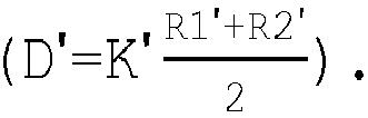
inlet portion 117a and the curvature radius R1' of thefirst face 118a comprised between 0.02 and 6, for an inlet speed VI' comprised between 20 m/s and 250 m/s; and - the radial distance D' between the curvature center C1' of the first curve and the curvature center C2' of the second curve equal to the arithmetic mean of the curvature radius R1' of the first curve and the curvature radius R2' of the second curve, calculated with a multiplicative coefficient K', for example of less than 10
- According to one embodiment, illustrated in
figure 12 , a gas turbine unit (only partially illustrated) comprises acooling circuit 212 which extends partially through turbine stator vanes 201 andturbine rotor blades 208. The cooling circuit comprises, at least in a turbine stage, aring 213 having a U-shaped cross section and defining anannular chamber 214. Thering 213 joins the ends of theturbine stator vanes 210 and, apart from having a structural function, also acts as a recipient to convey the cooling airflow towards the portion of the cooling circuit that extends inside theturbine rotor blades 208. Thering 213 is equipped with a pre-swirler 215 that comprises a plurality offlow channels 217. According to one embodiment, theflow channels 217 are defined by holes that join thechamber 214 with the external part of thering 213 and extend diagonally in relation to the main axis A". Theflow channels 217 are shaped to impart a rotation about the main axis A" by Coanda effect according to the cooling airflow speed, essentially as described above. In particular, theflow channels 217 form a first curve, with an internal wall that imparts the highest rotation at low speeds of the cooling airflow; and a second curve that imparts a rotation opposite to that imparted by the first curve when the speed of the cooling airflow approaches the critical threshold. - Lastly, it is clear that modifications and variations may be made to the gas turbine unit described herein without departing from the scope of the present invention, as described in the appended claims.
Claims (9)
- A gas turbine unit comprising:a compressor (4) and a turbine (5), extending along a main axis (A; A'; A");a cooling circuit (12; 112; 212) configured to convey a cooling airflow (AF; AF') from the compressor (4) toward the turbine (5); anda pre-swirler (15; 115; 215), arranged along the cooling circuit (12; 112; 212) and configured to impart a rotation about the main axis (A; A'; A") to the cooling airflow (AF; AF');the pre-swirler (15; 115; 215) comprising a plurality of flow channels (17; 117; 217) each having an inlet portion (17a; 117a) with a first passage section (S1; S1'), an outlet portion (17b; 117b) with a second passage section (S2; S2'), and a joining section (17c; 117c) between the inlet portion (17a; 117a) and the outlet portion (17b; 117b);the joining section (17c; 117c) forming a first curve shaped so that a first wall (17d; 118a) of the joining section (17c; 117c), defining an inner side of the first curve, deviates the cooling airflow (AF; AF') about the main axis (A; A'; A") by Coanda effect of an angle correlated to an absolute value of an inlet speed (VI) of the cooling airflow (AF; AF');the second passage section (S2) of the outlet portion (17b; 117b) being such as to allow a plurality of outlet angles of the cooling airflow (AF; AF'), in accordance with the rotation caused by the joining section (17c; 117c).
- The gas turbine unit according to claim 1, wherein the first wall (17d; 118a) of the joining section (17c; 117c) is configured so that the cooling airflow (AF; AF') is deflected about the main axis (A, A'; A") by a greater angle when the inlet speed (VI) is lower in absolute value and by a smaller angle when the inlet speed (VI) is greater in absolute value.
- The gas turbine unit according to claim 1 or 2, wherein the flow channels (17; 117; 217) are shaped so that an outlet speed (VO) of the cooling airflow (AF; AF') at an outlet of the pre-swirler (15; 115; 215) forms an outlet angle (α) comprised between 40° and 89°, with respect to a direction of the inlet speed (VI).
- The gas turbine unit according to any one of the foregoing claims, wherein a ratio between the first passage section (S1; S1') of the inlet portion (17a; 117a) and the second passage section (S2; S2') of the outlet portion (17b; 117b) is comprised between 0.3 and 3.
- The gas turbine unit according to any one of the foregoing claims, wherein a ratio between an equivalent diameter of the first passage section (S1; S1') of the inlet portion (17a; 117a) and a first curvature radius (R1; R1') of the first wall (17d; 118a) is comprised between 0.02 and 6.
- The gas turbine unit according to claim 5, wherein each flow channel (17; 117; 217) is delimitated by a second wall (17e; 118b) opposite to the first wall (17d; 118a) and defining a second curve that, when lapped against by the cooling airflow (AF; AF'), by Coanda effect imparts to the cooling airflow (AF; AF') a rotation opposite to the rotation imparted by the first curve.
- The gas turbine unit according to claim 6, wherein the second curve is arranged at a portion of the second wall (17d; 118b) reached by the cooling airflow (AF; AF') when the absolute value of the inlet speed (VI) is greater than a threshold and non-interacting with the cooling airflow (AF; AF') when the absolute value of the inlet speed (VI) is lower than the threshold.
- The gas turbine unit according to any one of claims 5 to 7, wherein a radial distance (D) between a curvature center (C1; C1') of the first curve and a curvature center (C2; C2') of the second curve is correlated to the first curvature radius (R1; R1') of the first curve and to a second curvature radius (R2; R2') of the second curve.
- The gas turbine unit according to claim 8, wherein the radial distance (D) between the curvature center (C1; C1') of the first curve and the curvature center (C2; C2') of the second curve is proportional to an average of the first curvature radius (R1; R1') of the first curve and the second curvature radius (R2; R2') of the second curve.
Applications Claiming Priority (1)
| Application Number | Priority Date | Filing Date | Title |
|---|---|---|---|
| ITUB2015A003103A ITUB20153103A1 (en) | 2015-08-13 | 2015-08-13 | GAS TURBINE GROUP WITH ADAPTIVE PRE-VECTOR |
Publications (2)
| Publication Number | Publication Date |
|---|---|
| EP3130753A1 true EP3130753A1 (en) | 2017-02-15 |
| EP3130753B1 EP3130753B1 (en) | 2022-03-30 |
Family
ID=54542410
Family Applications (1)
| Application Number | Title | Priority Date | Filing Date |
|---|---|---|---|
| EP16184087.1A Active EP3130753B1 (en) | 2015-08-13 | 2016-08-12 | Gas turbine unit with adaptive pre-swirler |
Country Status (3)
| Country | Link |
|---|---|
| EP (1) | EP3130753B1 (en) |
| CN (1) | CN106438046B (en) |
| IT (1) | ITUB20153103A1 (en) |
Cited By (3)
| Publication number | Priority date | Publication date | Assignee | Title |
|---|---|---|---|---|
| WO2021015861A1 (en) * | 2019-07-25 | 2021-01-28 | Siemens Energy Global GmbH & Co. KG | Pre-swirler adjustability in gas turbine engine |
| FR3101670A1 (en) * | 2019-10-08 | 2021-04-09 | Safran Aircraft Engines | Injector for a high pressure turbine |
| DE102023103082A1 (en) * | 2023-02-08 | 2024-08-08 | Rolls-Royce Deutschland Ltd & Co Kg | Pre-swirl nozzle system in a gas turbine and pre-swirl nozzle process |
Families Citing this family (3)
| Publication number | Priority date | Publication date | Assignee | Title |
|---|---|---|---|---|
| CN108071492B (en) * | 2017-12-19 | 2024-07-23 | 中国联合重型燃气轮机技术有限公司 | Gas turbine and pre-rotation flow dividing device thereof |
| EP3882479A1 (en) | 2020-03-17 | 2021-09-22 | Dresser-Rand SAS | Coupling guard for a rotating member |
| CN112275703A (en) * | 2020-09-30 | 2021-01-29 | 南京华易泰电子科技有限公司 | Water jet cutter structure utilizing coanda effect |
Citations (3)
| Publication number | Priority date | Publication date | Assignee | Title |
|---|---|---|---|---|
| GB2260787A (en) * | 1991-10-21 | 1993-04-28 | Gen Electric | Cooling air stator to rotor flow inducer in gas turbine engines |
| US20110250057A1 (en) * | 2010-04-12 | 2011-10-13 | Laurello Vincent P | Radial pre-swirl assembly and cooling fluid metering structure for a gas turbine engine |
| US20130045083A1 (en) * | 2011-08-18 | 2013-02-21 | Vincent P. Laurello | Turbine rotor disk inlet orifice for a turbine engine |
Family Cites Families (3)
| Publication number | Priority date | Publication date | Assignee | Title |
|---|---|---|---|---|
| US6431820B1 (en) * | 2001-02-28 | 2002-08-13 | General Electric Company | Methods and apparatus for cooling gas turbine engine blade tips |
| EP2503101A2 (en) * | 2011-03-22 | 2012-09-26 | General Electric Company | System for regulating a cooling fluid within a turbomachine |
| US9175566B2 (en) * | 2012-09-26 | 2015-11-03 | Solar Turbines Incorporated | Gas turbine engine preswirler with angled holes |
-
2015
- 2015-08-13 IT ITUB2015A003103A patent/ITUB20153103A1/en unknown
-
2016
- 2016-08-12 EP EP16184087.1A patent/EP3130753B1/en active Active
- 2016-08-12 CN CN201610893530.2A patent/CN106438046B/en active Active
Patent Citations (3)
| Publication number | Priority date | Publication date | Assignee | Title |
|---|---|---|---|---|
| GB2260787A (en) * | 1991-10-21 | 1993-04-28 | Gen Electric | Cooling air stator to rotor flow inducer in gas turbine engines |
| US20110250057A1 (en) * | 2010-04-12 | 2011-10-13 | Laurello Vincent P | Radial pre-swirl assembly and cooling fluid metering structure for a gas turbine engine |
| US20130045083A1 (en) * | 2011-08-18 | 2013-02-21 | Vincent P. Laurello | Turbine rotor disk inlet orifice for a turbine engine |
Cited By (10)
| Publication number | Priority date | Publication date | Assignee | Title |
|---|---|---|---|---|
| WO2021015861A1 (en) * | 2019-07-25 | 2021-01-28 | Siemens Energy Global GmbH & Co. KG | Pre-swirler adjustability in gas turbine engine |
| CN114127391A (en) * | 2019-07-25 | 2022-03-01 | 西门子能源全球两合公司 | Pre-swirler adjustability in gas turbine engines |
| JP2022541934A (en) * | 2019-07-25 | 2022-09-28 | シーメンス エナジー グローバル ゲゼルシャフト ミット ベシュレンクテル ハフツング ウント コンパニー コマンディートゲゼルシャフト | Gas Turbine Engine Pre-swirl Adjustment |
| JP7216249B2 (en) | 2019-07-25 | 2023-01-31 | シーメンス エナジー グローバル ゲゼルシャフト ミット ベシュレンクテル ハフツング ウント コンパニー コマンディートゲゼルシャフト | Gas Turbine Engine Pre-swirl Adjustment |
| CN114127391B (en) * | 2019-07-25 | 2023-05-12 | 西门子能源全球两合公司 | Pre-swirler adjustability in a gas turbine engine |
| US12173609B2 (en) | 2019-07-25 | 2024-12-24 | Siemens Energy Global GmbH & Co. KG | Pre-swirler adjustability in gas turbine engine |
| FR3101670A1 (en) * | 2019-10-08 | 2021-04-09 | Safran Aircraft Engines | Injector for a high pressure turbine |
| WO2021069838A1 (en) * | 2019-10-08 | 2021-04-15 | Safran Aircraft Engines | Injector for a high-pressure turbine |
| US11913350B2 (en) | 2019-10-08 | 2024-02-27 | Safran Aircraft Engines | Injector for a high-pressure turbine |
| DE102023103082A1 (en) * | 2023-02-08 | 2024-08-08 | Rolls-Royce Deutschland Ltd & Co Kg | Pre-swirl nozzle system in a gas turbine and pre-swirl nozzle process |
Also Published As
| Publication number | Publication date |
|---|---|
| CN106438046A (en) | 2017-02-22 |
| ITUB20153103A1 (en) | 2017-02-13 |
| EP3130753B1 (en) | 2022-03-30 |
| CN106438046B (en) | 2020-11-20 |
Similar Documents
| Publication | Publication Date | Title |
|---|---|---|
| EP3130753B1 (en) | Gas turbine unit with adaptive pre-swirler | |
| US10480531B2 (en) | Axial flow compressor, gas turbine including the same, and stator blade of axial flow compressor | |
| EP3350452B1 (en) | High stiffness turbomachine impeller, turbomachine including said impeller and method of manufacturing | |
| US9404368B2 (en) | Blade cascade and turbomachine | |
| US10436044B2 (en) | Guide vane segment for a turbomachine | |
| US10221854B2 (en) | Impeller and rotary machine provided with same | |
| KR102373727B1 (en) | Blade with stress-reducing bulbous projection at turn opening of coolant passages | |
| KR102377650B1 (en) | Intermediate central passage spanning outer walls aft of airfoil leading edge passage | |
| US10316677B2 (en) | Shroud arrangement of a row of blades of stator vanes or rotor blades | |
| US7704048B2 (en) | Turbine airfoil with controlled area cooling arrangement | |
| US9091170B2 (en) | One-stage stator vane cooling structure and gas turbine | |
| WO2015056455A1 (en) | Compressor and gas turbine | |
| US10151320B2 (en) | Compressor and gas turbine | |
| US11242759B2 (en) | Turbine blade and gas turbine | |
| CA3166702A1 (en) | Diffuser pipe with curved cross-sectional shapes | |
| US11326457B2 (en) | Blade and machine having the same | |
| CN111828098B (en) | Turbine engine airfoil with trailing edge and cooling method thereof | |
| CN109854376B (en) | Axial compressor for a gas turbine engine and gas turbine engine comprising said axial compressor | |
| US10378545B2 (en) | Fluid flow machine with high performance | |
| US10077778B2 (en) | Multistage centrifugal compressor | |
| US10774664B2 (en) | Plenum for cooling turbine flowpath components and blades | |
| US20110097198A1 (en) | Turbo machine efficiency equalizer system | |
| US10550710B2 (en) | Shroud for gas turbine engine | |
| US10100844B2 (en) | Multi-stage-type compressor and gas turbine equipped therewith | |
| US10605085B2 (en) | Gas turbine disk |
Legal Events
| Date | Code | Title | Description |
|---|---|---|---|
| PUAI | Public reference made under article 153(3) epc to a published international application that has entered the european phase |
Free format text: ORIGINAL CODE: 0009012 |
|
| STAA | Information on the status of an ep patent application or granted ep patent |
Free format text: STATUS: THE APPLICATION HAS BEEN PUBLISHED |
|
| AK | Designated contracting states |
Kind code of ref document: A1 Designated state(s): AL AT BE BG CH CY CZ DE DK EE ES FI FR GB GR HR HU IE IS IT LI LT LU LV MC MK MT NL NO PL PT RO RS SE SI SK SM TR |
|
| AX | Request for extension of the european patent |
Extension state: BA ME |
|
| RIN1 | Information on inventor provided before grant (corrected) |
Inventor name: MANTERO, MARCO Inventor name: TAPPANI, MARCO |
|
| STAA | Information on the status of an ep patent application or granted ep patent |
Free format text: STATUS: REQUEST FOR EXAMINATION WAS MADE |
|
| 17P | Request for examination filed |
Effective date: 20170816 |
|
| RBV | Designated contracting states (corrected) |
Designated state(s): AL AT BE BG CH CY CZ DE DK EE ES FI FR GB GR HR HU IE IS IT LI LT LU LV MC MK MT NL NO PL PT RO RS SE SI SK SM TR |
|
| RAP1 | Party data changed (applicant data changed or rights of an application transferred) |
Owner name: ANSALDO ENERGIA S.P.A. |
|
| STAA | Information on the status of an ep patent application or granted ep patent |
Free format text: STATUS: EXAMINATION IS IN PROGRESS |
|
| 17Q | First examination report despatched |
Effective date: 20190613 |
|
| GRAP | Despatch of communication of intention to grant a patent |
Free format text: ORIGINAL CODE: EPIDOSNIGR1 |
|
| STAA | Information on the status of an ep patent application or granted ep patent |
Free format text: STATUS: GRANT OF PATENT IS INTENDED |
|
| INTG | Intention to grant announced |
Effective date: 20211021 |
|
| GRAS | Grant fee paid |
Free format text: ORIGINAL CODE: EPIDOSNIGR3 |
|
| GRAA | (expected) grant |
Free format text: ORIGINAL CODE: 0009210 |
|
| STAA | Information on the status of an ep patent application or granted ep patent |
Free format text: STATUS: THE PATENT HAS BEEN GRANTED |
|
| AK | Designated contracting states |
Kind code of ref document: B1 Designated state(s): AL AT BE BG CH CY CZ DE DK EE ES FI FR GB GR HR HU IE IS IT LI LT LU LV MC MK MT NL NO PL PT RO RS SE SI SK SM TR |
|
| REG | Reference to a national code |
Ref country code: GB Ref legal event code: FG4D |
|
| REG | Reference to a national code |
Ref country code: CH Ref legal event code: EP |
|
| REG | Reference to a national code |
Ref country code: AT Ref legal event code: REF Ref document number: 1479360 Country of ref document: AT Kind code of ref document: T Effective date: 20220415 |
|
| REG | Reference to a national code |
Ref country code: DE Ref legal event code: R096 Ref document number: 602016070438 Country of ref document: DE |
|
| REG | Reference to a national code |
Ref country code: IE Ref legal event code: FG4D |
|
| REG | Reference to a national code |
Ref country code: LT Ref legal event code: MG9D |
|
| PG25 | Lapsed in a contracting state [announced via postgrant information from national office to epo] |
Ref country code: SE Free format text: LAPSE BECAUSE OF FAILURE TO SUBMIT A TRANSLATION OF THE DESCRIPTION OR TO PAY THE FEE WITHIN THE PRESCRIBED TIME-LIMIT Effective date: 20220330 Ref country code: RS Free format text: LAPSE BECAUSE OF FAILURE TO SUBMIT A TRANSLATION OF THE DESCRIPTION OR TO PAY THE FEE WITHIN THE PRESCRIBED TIME-LIMIT Effective date: 20220330 Ref country code: NO Free format text: LAPSE BECAUSE OF FAILURE TO SUBMIT A TRANSLATION OF THE DESCRIPTION OR TO PAY THE FEE WITHIN THE PRESCRIBED TIME-LIMIT Effective date: 20220630 Ref country code: LT Free format text: LAPSE BECAUSE OF FAILURE TO SUBMIT A TRANSLATION OF THE DESCRIPTION OR TO PAY THE FEE WITHIN THE PRESCRIBED TIME-LIMIT Effective date: 20220330 Ref country code: HR Free format text: LAPSE BECAUSE OF FAILURE TO SUBMIT A TRANSLATION OF THE DESCRIPTION OR TO PAY THE FEE WITHIN THE PRESCRIBED TIME-LIMIT Effective date: 20220330 Ref country code: BG Free format text: LAPSE BECAUSE OF FAILURE TO SUBMIT A TRANSLATION OF THE DESCRIPTION OR TO PAY THE FEE WITHIN THE PRESCRIBED TIME-LIMIT Effective date: 20220630 |
|
| REG | Reference to a national code |
Ref country code: NL Ref legal event code: MP Effective date: 20220330 |
|
| REG | Reference to a national code |
Ref country code: AT Ref legal event code: MK05 Ref document number: 1479360 Country of ref document: AT Kind code of ref document: T Effective date: 20220330 |
|
| PG25 | Lapsed in a contracting state [announced via postgrant information from national office to epo] |
Ref country code: LV Free format text: LAPSE BECAUSE OF FAILURE TO SUBMIT A TRANSLATION OF THE DESCRIPTION OR TO PAY THE FEE WITHIN THE PRESCRIBED TIME-LIMIT Effective date: 20220330 Ref country code: GR Free format text: LAPSE BECAUSE OF FAILURE TO SUBMIT A TRANSLATION OF THE DESCRIPTION OR TO PAY THE FEE WITHIN THE PRESCRIBED TIME-LIMIT Effective date: 20220701 Ref country code: FI Free format text: LAPSE BECAUSE OF FAILURE TO SUBMIT A TRANSLATION OF THE DESCRIPTION OR TO PAY THE FEE WITHIN THE PRESCRIBED TIME-LIMIT Effective date: 20220330 |
|
| PG25 | Lapsed in a contracting state [announced via postgrant information from national office to epo] |
Ref country code: NL Free format text: LAPSE BECAUSE OF FAILURE TO SUBMIT A TRANSLATION OF THE DESCRIPTION OR TO PAY THE FEE WITHIN THE PRESCRIBED TIME-LIMIT Effective date: 20220330 |
|
| PG25 | Lapsed in a contracting state [announced via postgrant information from national office to epo] |
Ref country code: SM Free format text: LAPSE BECAUSE OF FAILURE TO SUBMIT A TRANSLATION OF THE DESCRIPTION OR TO PAY THE FEE WITHIN THE PRESCRIBED TIME-LIMIT Effective date: 20220330 Ref country code: SK Free format text: LAPSE BECAUSE OF FAILURE TO SUBMIT A TRANSLATION OF THE DESCRIPTION OR TO PAY THE FEE WITHIN THE PRESCRIBED TIME-LIMIT Effective date: 20220330 Ref country code: RO Free format text: LAPSE BECAUSE OF FAILURE TO SUBMIT A TRANSLATION OF THE DESCRIPTION OR TO PAY THE FEE WITHIN THE PRESCRIBED TIME-LIMIT Effective date: 20220330 Ref country code: PT Free format text: LAPSE BECAUSE OF FAILURE TO SUBMIT A TRANSLATION OF THE DESCRIPTION OR TO PAY THE FEE WITHIN THE PRESCRIBED TIME-LIMIT Effective date: 20220801 Ref country code: ES Free format text: LAPSE BECAUSE OF FAILURE TO SUBMIT A TRANSLATION OF THE DESCRIPTION OR TO PAY THE FEE WITHIN THE PRESCRIBED TIME-LIMIT Effective date: 20220330 Ref country code: EE Free format text: LAPSE BECAUSE OF FAILURE TO SUBMIT A TRANSLATION OF THE DESCRIPTION OR TO PAY THE FEE WITHIN THE PRESCRIBED TIME-LIMIT Effective date: 20220330 Ref country code: CZ Free format text: LAPSE BECAUSE OF FAILURE TO SUBMIT A TRANSLATION OF THE DESCRIPTION OR TO PAY THE FEE WITHIN THE PRESCRIBED TIME-LIMIT Effective date: 20220330 Ref country code: AT Free format text: LAPSE BECAUSE OF FAILURE TO SUBMIT A TRANSLATION OF THE DESCRIPTION OR TO PAY THE FEE WITHIN THE PRESCRIBED TIME-LIMIT Effective date: 20220330 |
|
| PG25 | Lapsed in a contracting state [announced via postgrant information from national office to epo] |
Ref country code: PL Free format text: LAPSE BECAUSE OF FAILURE TO SUBMIT A TRANSLATION OF THE DESCRIPTION OR TO PAY THE FEE WITHIN THE PRESCRIBED TIME-LIMIT Effective date: 20220330 Ref country code: IS Free format text: LAPSE BECAUSE OF FAILURE TO SUBMIT A TRANSLATION OF THE DESCRIPTION OR TO PAY THE FEE WITHIN THE PRESCRIBED TIME-LIMIT Effective date: 20220730 Ref country code: AL Free format text: LAPSE BECAUSE OF FAILURE TO SUBMIT A TRANSLATION OF THE DESCRIPTION OR TO PAY THE FEE WITHIN THE PRESCRIBED TIME-LIMIT Effective date: 20220330 |
|
| REG | Reference to a national code |
Ref country code: DE Ref legal event code: R097 Ref document number: 602016070438 Country of ref document: DE |
|
| PG25 | Lapsed in a contracting state [announced via postgrant information from national office to epo] |
Ref country code: DK Free format text: LAPSE BECAUSE OF FAILURE TO SUBMIT A TRANSLATION OF THE DESCRIPTION OR TO PAY THE FEE WITHIN THE PRESCRIBED TIME-LIMIT Effective date: 20220330 |
|
| PLBE | No opposition filed within time limit |
Free format text: ORIGINAL CODE: 0009261 |
|
| STAA | Information on the status of an ep patent application or granted ep patent |
Free format text: STATUS: NO OPPOSITION FILED WITHIN TIME LIMIT |
|
| 26N | No opposition filed |
Effective date: 20230103 |
|
| PG25 | Lapsed in a contracting state [announced via postgrant information from national office to epo] |
Ref country code: MC Free format text: LAPSE BECAUSE OF FAILURE TO SUBMIT A TRANSLATION OF THE DESCRIPTION OR TO PAY THE FEE WITHIN THE PRESCRIBED TIME-LIMIT Effective date: 20220330 |
|
| REG | Reference to a national code |
Ref country code: CH Ref legal event code: PL |
|
| GBPC | Gb: european patent ceased through non-payment of renewal fee |
Effective date: 20220812 |
|
| PG25 | Lapsed in a contracting state [announced via postgrant information from national office to epo] |
Ref country code: LU Free format text: LAPSE BECAUSE OF NON-PAYMENT OF DUE FEES Effective date: 20220812 Ref country code: LI Free format text: LAPSE BECAUSE OF NON-PAYMENT OF DUE FEES Effective date: 20220831 Ref country code: CH Free format text: LAPSE BECAUSE OF NON-PAYMENT OF DUE FEES Effective date: 20220831 |
|
| REG | Reference to a national code |
Ref country code: BE Ref legal event code: MM Effective date: 20220831 |
|
| PG25 | Lapsed in a contracting state [announced via postgrant information from national office to epo] |
Ref country code: SI Free format text: LAPSE BECAUSE OF FAILURE TO SUBMIT A TRANSLATION OF THE DESCRIPTION OR TO PAY THE FEE WITHIN THE PRESCRIBED TIME-LIMIT Effective date: 20220330 |
|
| PG25 | Lapsed in a contracting state [announced via postgrant information from national office to epo] |
Ref country code: IE Free format text: LAPSE BECAUSE OF NON-PAYMENT OF DUE FEES Effective date: 20220812 Ref country code: FR Free format text: LAPSE BECAUSE OF NON-PAYMENT OF DUE FEES Effective date: 20220831 |
|
| PG25 | Lapsed in a contracting state [announced via postgrant information from national office to epo] |
Ref country code: BE Free format text: LAPSE BECAUSE OF NON-PAYMENT OF DUE FEES Effective date: 20220831 |
|
| PG25 | Lapsed in a contracting state [announced via postgrant information from national office to epo] |
Ref country code: GB Free format text: LAPSE BECAUSE OF NON-PAYMENT OF DUE FEES Effective date: 20220812 |
|
| PG25 | Lapsed in a contracting state [announced via postgrant information from national office to epo] |
Ref country code: HU Free format text: LAPSE BECAUSE OF FAILURE TO SUBMIT A TRANSLATION OF THE DESCRIPTION OR TO PAY THE FEE WITHIN THE PRESCRIBED TIME-LIMIT; INVALID AB INITIO Effective date: 20160812 |
|
| PG25 | Lapsed in a contracting state [announced via postgrant information from national office to epo] |
Ref country code: CY Free format text: LAPSE BECAUSE OF FAILURE TO SUBMIT A TRANSLATION OF THE DESCRIPTION OR TO PAY THE FEE WITHIN THE PRESCRIBED TIME-LIMIT Effective date: 20220330 |
|
| PG25 | Lapsed in a contracting state [announced via postgrant information from national office to epo] |
Ref country code: MK Free format text: LAPSE BECAUSE OF FAILURE TO SUBMIT A TRANSLATION OF THE DESCRIPTION OR TO PAY THE FEE WITHIN THE PRESCRIBED TIME-LIMIT Effective date: 20220330 |
|
| P01 | Opt-out of the competence of the unified patent court (upc) registered |
Effective date: 20240430 |
|
| PG25 | Lapsed in a contracting state [announced via postgrant information from national office to epo] |
Ref country code: MT Free format text: LAPSE BECAUSE OF FAILURE TO SUBMIT A TRANSLATION OF THE DESCRIPTION OR TO PAY THE FEE WITHIN THE PRESCRIBED TIME-LIMIT Effective date: 20220330 |
|
| PGFP | Annual fee paid to national office [announced via postgrant information from national office to epo] |
Ref country code: DE Payment date: 20250819 Year of fee payment: 10 |
|
| PGFP | Annual fee paid to national office [announced via postgrant information from national office to epo] |
Ref country code: IT Payment date: 20250829 Year of fee payment: 10 |
|
| PG25 | Lapsed in a contracting state [announced via postgrant information from national office to epo] |
Ref country code: TR Free format text: LAPSE BECAUSE OF FAILURE TO SUBMIT A TRANSLATION OF THE DESCRIPTION OR TO PAY THE FEE WITHIN THE PRESCRIBED TIME-LIMIT Effective date: 20220330 |