EP3130747A1 - Systems and methods for cleaning a well face during formation testing operations - Google Patents
Systems and methods for cleaning a well face during formation testing operations Download PDFInfo
- Publication number
- EP3130747A1 EP3130747A1 EP16179206.4A EP16179206A EP3130747A1 EP 3130747 A1 EP3130747 A1 EP 3130747A1 EP 16179206 A EP16179206 A EP 16179206A EP 3130747 A1 EP3130747 A1 EP 3130747A1
- Authority
- EP
- European Patent Office
- Prior art keywords
- formation
- probe
- retractable
- cleansing fluid
- cleaning mechanism
- Prior art date
- Legal status (The legal status is an assumption and is not a legal conclusion. Google has not performed a legal analysis and makes no representation as to the accuracy of the status listed.)
- Withdrawn
Links
- 230000015572 biosynthetic process Effects 0.000 title claims abstract description 113
- 238000004140 cleaning Methods 0.000 title claims abstract description 52
- 238000000034 method Methods 0.000 title claims abstract description 38
- 238000012360 testing method Methods 0.000 title claims abstract description 15
- 239000000523 sample Substances 0.000 claims abstract description 86
- 239000012530 fluid Substances 0.000 claims abstract description 83
- 230000007246 mechanism Effects 0.000 claims abstract description 52
- XLYOFNOQVPJJNP-UHFFFAOYSA-N water Substances O XLYOFNOQVPJJNP-UHFFFAOYSA-N 0.000 claims description 11
- 239000004094 surface-active agent Substances 0.000 claims description 5
- 238000005755 formation reaction Methods 0.000 description 103
- 238000005553 drilling Methods 0.000 description 44
- 239000000126 substance Substances 0.000 description 6
- 230000008901 benefit Effects 0.000 description 4
- 238000004891 communication Methods 0.000 description 3
- 238000005259 measurement Methods 0.000 description 3
- 239000000203 mixture Substances 0.000 description 3
- 230000008569 process Effects 0.000 description 3
- 238000005070 sampling Methods 0.000 description 3
- 239000002904 solvent Substances 0.000 description 3
- 239000004020 conductor Substances 0.000 description 2
- 238000011161 development Methods 0.000 description 2
- 238000011156 evaluation Methods 0.000 description 2
- 238000003860 storage Methods 0.000 description 2
- 239000004215 Carbon black (E152) Substances 0.000 description 1
- 230000009471 action Effects 0.000 description 1
- 239000000654 additive Substances 0.000 description 1
- 230000000996 additive effect Effects 0.000 description 1
- 230000004075 alteration Effects 0.000 description 1
- 238000010276 construction Methods 0.000 description 1
- 238000011109 contamination Methods 0.000 description 1
- 238000005520 cutting process Methods 0.000 description 1
- 238000013461 design Methods 0.000 description 1
- 238000010586 diagram Methods 0.000 description 1
- 238000000605 extraction Methods 0.000 description 1
- 239000000835 fiber Substances 0.000 description 1
- 239000012634 fragment Substances 0.000 description 1
- 239000013505 freshwater Substances 0.000 description 1
- 230000006870 function Effects 0.000 description 1
- 229930195733 hydrocarbon Natural products 0.000 description 1
- 150000002430 hydrocarbons Chemical class 0.000 description 1
- 238000002347 injection Methods 0.000 description 1
- 239000007924 injection Substances 0.000 description 1
- 238000004519 manufacturing process Methods 0.000 description 1
- 238000012986 modification Methods 0.000 description 1
- 230000004048 modification Effects 0.000 description 1
- 230000000149 penetrating effect Effects 0.000 description 1
- 230000002093 peripheral effect Effects 0.000 description 1
- 239000003348 petrochemical agent Substances 0.000 description 1
- 230000000704 physical effect Effects 0.000 description 1
- 238000005086 pumping Methods 0.000 description 1
- 238000007790 scraping Methods 0.000 description 1
- 238000007789 sealing Methods 0.000 description 1
- 239000007787 solid Substances 0.000 description 1
- 239000007921 spray Substances 0.000 description 1
- 238000005507 spraying Methods 0.000 description 1
Images

Classifications
-
- E—FIXED CONSTRUCTIONS
- E21—EARTH OR ROCK DRILLING; MINING
- E21B—EARTH OR ROCK DRILLING; OBTAINING OIL, GAS, WATER, SOLUBLE OR MELTABLE MATERIALS OR A SLURRY OF MINERALS FROM WELLS
- E21B37/00—Methods or apparatus for cleaning boreholes or wells
-
- E—FIXED CONSTRUCTIONS
- E21—EARTH OR ROCK DRILLING; MINING
- E21B—EARTH OR ROCK DRILLING; OBTAINING OIL, GAS, WATER, SOLUBLE OR MELTABLE MATERIALS OR A SLURRY OF MINERALS FROM WELLS
- E21B37/00—Methods or apparatus for cleaning boreholes or wells
- E21B37/02—Scrapers specially adapted therefor
-
- E—FIXED CONSTRUCTIONS
- E21—EARTH OR ROCK DRILLING; MINING
- E21B—EARTH OR ROCK DRILLING; OBTAINING OIL, GAS, WATER, SOLUBLE OR MELTABLE MATERIALS OR A SLURRY OF MINERALS FROM WELLS
- E21B49/00—Testing the nature of borehole walls; Formation testing; Methods or apparatus for obtaining samples of soil or well fluids, specially adapted to earth drilling or wells
- E21B49/08—Obtaining fluid samples or testing fluids, in boreholes or wells
- E21B49/10—Obtaining fluid samples or testing fluids, in boreholes or wells using side-wall fluid samplers or testers
Definitions
- the present disclosure generally relates to testing and evaluation of subterranean formations and formation fluids and, more particularly, to systems and methods for cleaning a well face during formation testing operations.
- Recent formation tester tools generally have one or more probes for collecting samples of the formation fluids and may contain chambers for storage of the collected fluid samples.
- the probes To collect samples, the probes form a sealing surface with a wellbore wall and pump formation fluids out of the formation for testing.
- the probes To make an effective seal, the probes must penetrate through a drilling mud layer before reaching the wellbore wall.
- the drilling mud layer may compromise the seal between the probes and the wellbore wall and contaminate the sample with drilling mud. It is desirable to increase the efficacy of the formation tester tools by creating a stronger seal between the probes and the wellbore wall, thereby insuring a more accurate, less contaminated sample of formation fluids. Additionally, it is desirable to increase the efficacy of the formation tester tools by providing for repeated uses without extraction.
- the present disclosure generally relates to testing and evaluation of subterranean formations and formation fluids and, more particularly, to systems and methods for cleaning a well face during formation testing operations.
- Embodiments of the present disclosure may be applicable to horizontal, vertical, deviated, or otherwise nonlinear wellbores in any type of subterranean formation. Embodiments may be applicable to injection wells as well as production wells, including hydrocarbon wells. Devices and methods in accordance with certain embodiments may be used in one or more of wireline, measurement-while-drilling (MWD) and logging-while-drilling (LWD) operations.
- MWD measurement-while-drilling
- LWD logging-while-drilling
- Embodiments may be implemented in various formation tester tools suitable for testing, retrieval and sampling along sections of the formation that, for example, may be conveyed through flow passage in tubular string or using a wireline, slickline, coiled tubing, downhole robot or the like.
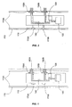
- Figure 1 illustrates a cross-sectional schematic of an example formation tester tool 100, which may be disposed in a wellbore 110 traversing earth formations.
- the interior of the wellbore wall may be covered wholly or partially by a drilling mud layer 110a.
- the drilling mud layer may be left over from a drilling operation in which drilling mud is pumped into the wellbore from the surface to lubricate and cool the drill bit while the drill bit is penetrating the formation.
- the drilling mud layer 110a may have varying levels of viscosity depending on the types of fluid and solid matter composing the layer, including chemicals from the drilling mud itself, petrochemical fluids from the formation, and geologic fragments left over from the drilling process.
- the drilling mud layer 110a may adhere, at least partially, to the wall of the wellbore 110.
- the formation tester tool 100 may be suitable for testing, retrieval and sampling along sections of the formation via wellbore 110.
- a formation tester tool may be conveyed in a wellbore by wireline (not shown), which may contain conductors for carrying power to the various components of the tool and conductors or cables (coaxial or fiber optic cables) for providing two-way data communication between tool 100 and an uphole control unit (not shown).
- the control unit preferably includes a computer and associated memory for storing programs and data.
- the control unit may generally control the operation of tool 100 and process data received from it during operations.
- the control unit may have a variety of associated peripherals, such as a recorder for recording data, a display for displaying desired information, printers and others. The use of the control unit, display and recorder are known in the art of well logging and are, thus, not discussed further.
- formation tester tool 100 may include a pump 120, which may be a double acting piston pump, for example.
- the pump 120 may control the fluid flow into and out of probes 130A and 130B via fluid flow line 140.
- the number of probes may vary depending on implementation.
- the pump 120 may pump fluid out of or into collection chamber 150.
- the collection chamber 150 may be of various sizes, for example one gallon.
- the collection chamber 15 may be totally or partially filled at the surface with a cleansing fluid prior to the formation tester tool 100 being lowered into the wellbore 110.
- the cleansing fluid may be water.
- the water may be fresh water from the surface or recycled water from other drilling operations.
- the cleansing fluid may be a mixture of water, or some other solvent, with surfactants and other chemicals.
- the cleansing fluid may be super-heated or super-cooled at the surface before being stored in the collection chamber 150.
- a control unit at the surface may engage the formation tester tool 100.
- Engaging the formation tester tool 100 may cause the pump to energize, ejecting the cleansing fluid out of the collection chamber 150, through the fluid flow line 140, and out of the formation tester tool 100 via ports within probes 130A and 130B, as shown in Fig. 1 .
- the ports as will be discussed below, may comprise slits, which focus the cleansing fluid, causing pressurized streams 160A and 160B to be sprayed from the probes 130A and 130B.
- the combination of the pressure of streams 160A and 160B and the characteristics of the cleansing fluid may combine to remove most or all of the drilling mud layer 110a from the wellbore in the area immediately adjacent to the probes 130A and 130B.
- the control unit may trigger setting rams 170A and 170B and probes 130A and 130B to extend outward from the formation tester tool 100, as shown in Fig. 2 .
- the setting rams 170A and 170B are shown located generally opposite probes 130A and 130B of the tool, but may be located elsewhere as necessary to stabilize the formation tester tool 100.
- the setting rams 170A and 170B and probes 130A and 130B may continue extending until each contacts the wellbore wall. For example, a flat or substantially flat face of the probes 130A and 130B may contact the wellbore wall. As can be seen in Fig.
- the contact location for probes 130A and 130B has been cleaned by the pumped cleansing fluid.
- the cleansing fluid out of the probes 130A and 130B the probes are insured to contact a location that is relatively clean of drilling mud as compared to the surrounding wellbore wall.
- the control unit may trigger the pump to begin drawing formation fluids into the formation tester tool 100, at least partially filling the collection chamber 150 with formation fluid.
- the pump 110 may cause formation fluids to be extracted from the formation and into the formation tester tool through the probes 130A and 130B via flow line 120. Because the wellbore wall has been cleansed of drilling mud, the probes 130A and 130B may contact the formation directly, without having to penetrate the drilling mud layer 110a. This leads to a more accurate sample of the formation fluids, without drilling mud contamination. Additionally, because the cleansing fluid in collection chamber 150 was used to cleanse the wellbore wall, the collection chamber 150 can be filled with a fresh sample of formation fluids via pump 120. Reusing collection chamber 150 increases the overall functionality of the formation tester tool 100 without requiring additional storage capacity.
- the cleansing fluid may include some combination of a solvent, such as water, and a chemical, such as a surfactant. Additionally, the cleansing fluid may be heated or cooled. The characteristics of the cleansing fluid may be tailored to the particular composition of the drilling mud layer, as determined at least by the wellbore, drilling, and formation characteristics. For example, in some instances, a drilling mud with a particular density and viscosity may be used to adequately lubricate a drill bit for the drilling process. Petrochemicals and other fluids, as well as cuttings from the formation, may become displaced within the drilling mud layer on the wellbore wall.
- the drilling mud layer composition may be determined based on a variety of information, such as measurements, recorded at the surface. Based on the information, a well site operator may optimize the cleansing fluid according to the drilling mud layer characteristics.
- the probes may be optimized to provide a pressurized stream of cleansing fluid.
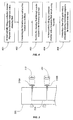
- the formation tester tool 300 includes two probes 310A and 310B. Each of the probes 310A and 310B are connected to a collection container and pump (not shown) via fluid flow line 320. When pumped, cleansing fluid may stream out of the face of probes 310A and 310B at slits 312 and 314. As can be seen, the slits may have a variety of configurations. The size and shape of slits 312 and 314 may be configured according to the viscosity of the cleansing fluid and the formation fluids to be collected in the formation tester tool 300.
- a formation tester tool may include a retractable cleaning mechanism that contacts a face of the probe and removes any mud buildup.
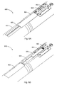
- Figs. 5A-B illustrate an example formation tester tool 500 that incorporates a retractable cleaning mechanism, retractable blade 504.
- the formation tester tool body 501 may be incorporated in a drill string for drilling operations.
- the retracted probe 502 may have a face 503 substantially coplanar with an outer surface of the formation tester tool body 503.
- the probe may be retracted into the position shown in Figs. 5A and 5B .
- the retractable blade 504 with edge 505 may be extended toward the probe 502 along a track 506, and contact a face 503 of the probe 502.
- the retractable blade 504 may be powered, for example, using hydraulic power or another power source that would be appreciated by one of ordinary skill in view of this disclosure.
- the edge 505 may remove drilling mud build-up on the face of the probe 502 through a scraping action.
- the retractable blade 504 may then be retracted, leaving the probe 502 uncovered for future sampling operations.
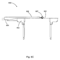
- Figs. 6A-C illustrate an example formation tester tool 600 that incorporates another retractable cleaning mechanism embodiment, retractable brush mechanism 606.
- the formation tester tool body 601 may be incorporated in a drill string for drilling operations.
- the formation tester tool 600 may include a cover plate 604 that protects the retractable brush mechanism 606 during drilling operations, for example. To expose the retractable brush mechanism 606, the cover plate may travel away from the probe 602 along track 605. When covered by the cover plate 604, the retractable brush mechanism 606 may fit into a slot 608 machined into the formation tester tool body 601.
- the retractable brush mechanism 606 may comprise a wedge shape 609 to accommodate the slot 608, and allow the cover plate 604 to slide freely over the retractable brush 606.
- an end of the retractable brush mechanism 606 may include at least one brush 607.
- the brush 607 may contact a face 603 of the probe 602 when the retractable brush mechanism 606 is extended.
- the brush 607 may rotate around a cylindrical mount as the retractable brush mechanism 606 is extended, removing drilling mud build-up from the face 603 as the brush 607 rotates.
- the cover plate 604 and the retractable brush mechanism 606 may be powered, for example, using hydraulic power or another power source that would be appreciated by one of ordinary skill in view of this disclosure.
- Other brush configurations are possible, including fixed brushes of different shapes and sizes.
- the retractable cleaning mechanisms are not limited to the embodiments shown herein, and may take a variety of shapes and sizes, depending on the application.
- the formation tester tool may include multiple retractable cleaning mechanisms.
- One retractable cleaning mechanism may contact a face of the probe, as described above.
- Another retractable cleaning mechanism may contact a formation at a position adjacent to the probe.
- setting rams such as setting rams 170A and 170B, may be extended, urging the side of the formation tester tool with the probes towards the borehole wall.
- a first retractable cleaning mechanism may then be extended, contacting the face of the borehole wall, and wiping some or all of the drilling mud away from the borehole wall.
- the first retractable cleaning mechanism may comprise a similar structure to the retractable cleaning mechanism 606, but may be disposed on an opposite side of the probe from the retractable cleaning mechanism 606.
- the first retractable cleaning mechanism may include a brush, for example, similar to the brush on retractable cleaning mechanism 606.
- cleansing fluid may be ejected from the probe at the same time the first retractable cleaning mechanism is contacting the borehole wall.
- the first retractable cleaning mechanism Once the first retractable cleaning mechanism has made a predetermined number of passes against the borehole wall, it may be retracted, and the probe may be extended to form a seal with the borehole wall.
- the probe Once a formation fluid sample has been taken, the probe may be retracted, and a second retractable cleaning mechanism, similar to retractable cleaning mechanism 606, may contact a face of the probe, removing any drilling mud that has become caked on the probe.
- Fig. 4 illustrates an example method incorporating aspects of the present invention.
- the method may include at least partially filling a collection chamber in a formation tester tool with a cleansing fluid.
- the cleansing fluid may include a solvent and a chemical, such as a surfactant, and may be temperature-controlled, such as super-heated or super-cooled.
- the cleansing fluid may be mixed at the drilling site or remotely at another location.
- the cleansing fluid may be shipped to the drilling site in a container, where it is pumped into a collection chamber in a formation tester tool, such as chamber 150 in formation tester tool 100 from Fig. 1 .
- the method may include positioning the formation tester tool at a first location in a wellbore.
- the formation tester tool may be lowered until a certain depth, matching particular formation strata, is reached.
- the particular depth may be determined by seismographic and other measurements of the formation.
- the formation tester tool may be lowered downhole as a part of other equipment, such as a drill string.
- Step 403 may include ejecting the cleansing fluid through a probe coupled to the formation tester tool.
- the first location may be predetermined according to the description above.
- Ejecting the cleansing fluid may include, but does not require, a control unit at the surface triggering a pump in the formation tester tool to spray the cleansing fluid from a collection container of the formation tester tool through probes of the formation tester tool at a drilling mud layer of the wellbore.
- Step 403 may occur before or during the extension of probes and setting rams of the formation tester tool outward to contact the wellbore wall.
- Step 404 may comprise at least partially filling the collection chamber with a formation fluid sample using the probe.
- the fluid may be pumped through a probe of the formation tester tool and stored in the collection chamber via a fluid flow line.
- the collected sample may be used to clean the drilling mud from a second location within the wellbore.
- Step 405 may comprise contacting a face of the probe with a retractable cleaning mechanism coupled to the formation tester tool.
- the probe may accumulate a drilling mud build-up as the probe is extended to take a formation sample.
- the retractable cleaning mechanism may remove most or all of the drilling-mud build up and allow the probe to be used again.
Landscapes
- Life Sciences & Earth Sciences (AREA)
- Engineering & Computer Science (AREA)
- Geology (AREA)
- Mining & Mineral Resources (AREA)
- Physics & Mathematics (AREA)
- Environmental & Geological Engineering (AREA)
- Fluid Mechanics (AREA)
- General Life Sciences & Earth Sciences (AREA)
- Geochemistry & Mineralogy (AREA)
- Sampling And Sample Adjustment (AREA)
Abstract
at least partially filling a collection chamber (150) with a cleansing fluid, wherein the filling chamber is disposed within a tool body (501) of a formation tool;
positioning the formation tester tool at a first location in a wellbore (110);
ejecting the cleansing fluid through a probe (130A, 130B, 310A, 310B, 502) extendable from the tool body;
at least partially filling the collection chamber with a formation fluid sample using the probe; and
contacting a face of the probe (503, 603) with a first retractable cleaning mechanism (606) coupled to the tool body when the probe is in a retracted position with respect to the tool body.
Description
- The present disclosure generally relates to testing and evaluation of subterranean formations and formation fluids and, more particularly, to systems and methods for cleaning a well face during formation testing operations.
- It is well known in the subterranean well drilling and completion art to perform tests on formations penetrated by a wellbore. Such tests are typically performed in order to determine geological or other physical properties of the formation and fluids contained therein. Measurements of parameters of the geological formation are typically performed using many devices including downhole formation tester tools. In certain applications, the tools may be used for logging-while-drilling (LWD) or measurement-while drilling (MWD) purposes.
- Recent formation tester tools generally have one or more probes for collecting samples of the formation fluids and may contain chambers for storage of the collected fluid samples. To collect samples, the probes form a sealing surface with a wellbore wall and pump formation fluids out of the formation for testing. To make an effective seal, the probes must penetrate through a drilling mud layer before reaching the wellbore wall. The drilling mud layer may compromise the seal between the probes and the wellbore wall and contaminate the sample with drilling mud. It is desirable to increase the efficacy of the formation tester tools by creating a stronger seal between the probes and the wellbore wall, thereby insuring a more accurate, less contaminated sample of formation fluids. Additionally, it is desirable to increase the efficacy of the formation tester tools by providing for repeated uses without extraction.
- Some specific exemplary embodiments of the disclosure may be understood by referring, in part, to the following description and the accompanying drawings.
-
Figure 1 is a cross-sectional schematic of an example formation tester tool in a wellbore according to aspects of the present disclosure. -
Figure 2 is a cross-sectional schematic of an example formation tester tool in a wellbore according to aspects of the present disclosure. -
Figure 3 is a partial diagram of a formation tester tool in a wellbore according to aspects of the present disclosure. -
Figure 4 is an example method for cleaning a well face during formation tester operations, incorporating aspects of the present disclosure. -
Figures 5A and 5B show an example formation tester tool with a retractable cleaning mechanism, according to aspects of the present disclosure. -
Figures 6A-C show an example formation tester tool with a retractable cleaning mechanism, according to aspects of the present disclosure. - While embodiments of this disclosure have been depicted and described and are defined by reference to exemplary embodiments of the disclosure, such references do not imply a limitation on the disclosure, and no such limitation is to be inferred. The subject matter disclosed is capable of considerable modification, alteration, and equivalents in form and function, as will occur to those skilled in the pertinent art and having the benefit of this disclosure. The depicted and described embodiments of this disclosure are examples only, and not exhaustive of the scope of the disclosure.
- The present disclosure generally relates to testing and evaluation of subterranean formations and formation fluids and, more particularly, to systems and methods for cleaning a well face during formation testing operations.
- Illustrative embodiments of the present invention are described in detail herein. In the interest of clarity, not all features of an actual implementation may be described in this specification. It will of course be appreciated that in the development of any such actual embodiment, numerous implementation-specific decisions must be made to achieve the specific implementation goals, which will vary from one implementation to another. Moreover, it will be appreciated that such a development effort might be complex and time-consuming, but would nevertheless be a routine undertaking for those of ordinary skill in the art having the benefit of the present disclosure.
- To facilitate a better understanding of the present invention, the following examples of certain embodiments are given. In no way should the following examples be read to limit, or define, the scope of the invention. Embodiments of the present disclosure may be applicable to horizontal, vertical, deviated, or otherwise nonlinear wellbores in any type of subterranean formation. Embodiments may be applicable to injection wells as well as production wells, including hydrocarbon wells. Devices and methods in accordance with certain embodiments may be used in one or more of wireline, measurement-while-drilling (MWD) and logging-while-drilling (LWD) operations. Embodiments may be implemented in various formation tester tools suitable for testing, retrieval and sampling along sections of the formation that, for example, may be conveyed through flow passage in tubular string or using a wireline, slickline, coiled tubing, downhole robot or the like.
-
Figure 1 illustrates a cross-sectional schematic of an example formation tester tool 100, which may be disposed in awellbore 110 traversing earth formations. The interior of the wellbore wall may be covered wholly or partially by a drilling mud layer 110a. The drilling mud layer may be left over from a drilling operation in which drilling mud is pumped into the wellbore from the surface to lubricate and cool the drill bit while the drill bit is penetrating the formation. The drilling mud layer 110a may have varying levels of viscosity depending on the types of fluid and solid matter composing the layer, including chemicals from the drilling mud itself, petrochemical fluids from the formation, and geologic fragments left over from the drilling process. As can be seen inFig. 1 , the drilling mud layer 110a may adhere, at least partially, to the wall of thewellbore 110. - The formation tester tool 100 may be suitable for testing, retrieval and sampling along sections of the formation via
wellbore 110. A formation tester tool may be conveyed in a wellbore by wireline (not shown), which may contain conductors for carrying power to the various components of the tool and conductors or cables (coaxial or fiber optic cables) for providing two-way data communication between tool 100 and an uphole control unit (not shown). The control unit preferably includes a computer and associated memory for storing programs and data. The control unit may generally control the operation of tool 100 and process data received from it during operations. The control unit may have a variety of associated peripherals, such as a recorder for recording data, a display for displaying desired information, printers and others. The use of the control unit, display and recorder are known in the art of well logging and are, thus, not discussed further. - As shown in
Figure 1 , formation tester tool 100 may include apump 120, which may be a double acting piston pump, for example. Thepump 120 may control the fluid flow into and out ofprobes fluid flow line 140. The number of probes may vary depending on implementation. - The
pump 120 may pump fluid out of or intocollection chamber 150. Thecollection chamber 150 may be of various sizes, for example one gallon. The collection chamber 15 may be totally or partially filled at the surface with a cleansing fluid prior to the formation tester tool 100 being lowered into thewellbore 110. In some embodiments the cleansing fluid may be water. The water may be fresh water from the surface or recycled water from other drilling operations. In some embodiments, the cleansing fluid may be a mixture of water, or some other solvent, with surfactants and other chemicals. In yet other embodiment, the cleansing fluid may be super-heated or super-cooled at the surface before being stored in thecollection chamber 150. - When the formation tester tool 100 is lowered downhole, and the formation tester tool 100 is positioned at a first location within a wellbore, such as at a pre-determined depth or formation strata, a control unit at the surface may engage the formation tester tool 100. Engaging the formation tester tool 100 may cause the pump to energize, ejecting the cleansing fluid out of the
collection chamber 150, through thefluid flow line 140, and out of the formation tester tool 100 via ports withinprobes Fig. 1 . The ports, as will be discussed below, may comprise slits, which focus the cleansing fluid, causingpressurized streams probes streams probes - During or after the cleansing fluid is sprayed out of
probes setting rams probes Fig. 2 . Thesetting rams opposite probes probes probes Fig. 2 , the contact location forprobes probes - Once the setting rams 170A and 170B and
probes collection chamber 150 with formation fluid. Thepump 110 may cause formation fluids to be extracted from the formation and into the formation tester tool through theprobes flow line 120. Because the wellbore wall has been cleansed of drilling mud, theprobes collection chamber 150 was used to cleanse the wellbore wall, thecollection chamber 150 can be filled with a fresh sample of formation fluids viapump 120. Reusingcollection chamber 150 increases the overall functionality of the formation tester tool 100 without requiring additional storage capacity. - As previously mentioned, the cleansing fluid may include some combination of a solvent, such as water, and a chemical, such as a surfactant. Additionally, the cleansing fluid may be heated or cooled. The characteristics of the cleansing fluid may be tailored to the particular composition of the drilling mud layer, as determined at least by the wellbore, drilling, and formation characteristics. For example, in some instances, a drilling mud with a particular density and viscosity may be used to adequately lubricate a drill bit for the drilling process. Petrochemicals and other fluids, as well as cuttings from the formation, may become displaced within the drilling mud layer on the wellbore wall. For particularly viscous drilling mud layers, some combination of chemicals and temperature variation in the cleansing fluid may be required to adequately cleanse the drilling mud from the wellbore wall. The drilling mud layer composition may be determined based on a variety of information, such as measurements, recorded at the surface. Based on the information, a well site operator may optimize the cleansing fluid according to the drilling mud layer characteristics.
- In addition to the cleansing fluid, the probes may be optimized to provide a pressurized stream of cleansing fluid. Two examples are shown in
Fig. 3 . As can be seen inFig. 3 , theformation tester tool 300 includes twoprobes probes fluid flow line 320. When pumped, cleansing fluid may stream out of the face ofprobes slits slits formation tester tool 300. - In some cases, the drilling mud may not be completely removed from the borehole wall before the probes are extended. In such cases, a layer of mud may form on the probe, limiting future operations. In certain embodiments, a formation tester tool incorporating aspects of the present disclosure may include a retractable cleaning mechanism that contacts a face of the probe and removes any mud buildup.
Figs. 5A-B illustrate an exampleformation tester tool 500 that incorporates a retractable cleaning mechanism,retractable blade 504. In the embodiment shown, the formationtester tool body 501 may be incorporated in a drill string for drilling operations. InFig. 5A , the retractedprobe 502 may have aface 503 substantially coplanar with an outer surface of the formationtester tool body 503. After theprobe 502 has been deployed, and formation fluid has been sampled, the probe may be retracted into the position shown inFigs. 5A and 5B . As can be seen inFig. 5B , theretractable blade 504, withedge 505 may be extended toward theprobe 502 along atrack 506, and contact aface 503 of theprobe 502. Theretractable blade 504 may be powered, for example, using hydraulic power or another power source that would be appreciated by one of ordinary skill in view of this disclosure. Theedge 505 may remove drilling mud build-up on the face of theprobe 502 through a scraping action. Theretractable blade 504 may then be retracted, leaving theprobe 502 uncovered for future sampling operations. -
Figs. 6A-C illustrate an exampleformation tester tool 600 that incorporates another retractable cleaning mechanism embodiment,retractable brush mechanism 606. In the embodiment shown, the formationtester tool body 601 may be incorporated in a drill string for drilling operations. As can be seen inFig. 6A , theformation tester tool 600 may include acover plate 604 that protects theretractable brush mechanism 606 during drilling operations, for example. To expose theretractable brush mechanism 606, the cover plate may travel away from theprobe 602 alongtrack 605. When covered by thecover plate 604, theretractable brush mechanism 606 may fit into aslot 608 machined into the formationtester tool body 601. Theretractable brush mechanism 606 may comprise awedge shape 609 to accommodate theslot 608, and allow thecover plate 604 to slide freely over theretractable brush 606. - As can be seen, an end of the
retractable brush mechanism 606 may include at least onebrush 607. Thebrush 607 may contact aface 603 of theprobe 602 when theretractable brush mechanism 606 is extended. Thebrush 607 may rotate around a cylindrical mount as theretractable brush mechanism 606 is extended, removing drilling mud build-up from theface 603 as thebrush 607 rotates. In certain embodiments, thecover plate 604 and theretractable brush mechanism 606 may be powered, for example, using hydraulic power or another power source that would be appreciated by one of ordinary skill in view of this disclosure. Other brush configurations are possible, including fixed brushes of different shapes and sizes. The retractable cleaning mechanisms are not limited to the embodiments shown herein, and may take a variety of shapes and sizes, depending on the application. - In certain embodiments, the formation tester tool may include multiple retractable cleaning mechanisms. One retractable cleaning mechanism may contact a face of the probe, as described above. Another retractable cleaning mechanism may contact a formation at a position adjacent to the probe. To use the multiple retractable cleaning mechanisms, setting rams, such as setting rams 170A and 170B, may be extended, urging the side of the formation tester tool with the probes towards the borehole wall. A first retractable cleaning mechanism may then be extended, contacting the face of the borehole wall, and wiping some or all of the drilling mud away from the borehole wall. In certain embodiments, the first retractable cleaning mechanism may comprise a similar structure to the
retractable cleaning mechanism 606, but may be disposed on an opposite side of the probe from theretractable cleaning mechanism 606. The first retractable cleaning mechanism may include a brush, for example, similar to the brush onretractable cleaning mechanism 606. - In certain embodiments, cleansing fluid may be ejected from the probe at the same time the first retractable cleaning mechanism is contacting the borehole wall. Once the first retractable cleaning mechanism has made a predetermined number of passes against the borehole wall, it may be retracted, and the probe may be extended to form a seal with the borehole wall. Once a formation fluid sample has been taken, the probe may be retracted, and a second retractable cleaning mechanism, similar to
retractable cleaning mechanism 606, may contact a face of the probe, removing any drilling mud that has become caked on the probe. -
Fig. 4 illustrates an example method incorporating aspects of the present invention. Atstep 401, the method may include at least partially filling a collection chamber in a formation tester tool with a cleansing fluid. As mentioned previously, the cleansing fluid may include a solvent and a chemical, such as a surfactant, and may be temperature-controlled, such as super-heated or super-cooled. The cleansing fluid may be mixed at the drilling site or remotely at another location. In some embodiments, the cleansing fluid may be shipped to the drilling site in a container, where it is pumped into a collection chamber in a formation tester tool, such aschamber 150 in formation tester tool 100 fromFig. 1 . - At
step 402, the method may include positioning the formation tester tool at a first location in a wellbore. The formation tester tool may be lowered until a certain depth, matching particular formation strata, is reached. The particular depth may be determined by seismographic and other measurements of the formation. In certain embodiments, the formation tester tool may be lowered downhole as a part of other equipment, such as a drill string. - Step 403 may include ejecting the cleansing fluid through a probe coupled to the formation tester tool. The first location may be predetermined according to the description above. Ejecting the cleansing fluid may include, but does not require, a control unit at the surface triggering a pump in the formation tester tool to spray the cleansing fluid from a collection container of the formation tester tool through probes of the formation tester tool at a drilling mud layer of the wellbore. Step 403 may occur before or during the extension of probes and setting rams of the formation tester tool outward to contact the wellbore wall.
- Step 404 may comprise at least partially filling the collection chamber with a formation fluid sample using the probe. The fluid may be pumped through a probe of the formation tester tool and stored in the collection chamber via a fluid flow line. In certain embodiments, the collected sample may be used to clean the drilling mud from a second location within the wellbore.
- Step 405 may comprise contacting a face of the probe with a retractable cleaning mechanism coupled to the formation tester tool. As described above, the probe may accumulate a drilling mud build-up as the probe is extended to take a formation sample. The retractable cleaning mechanism may remove most or all of the drilling-mud build up and allow the probe to be used again.
- Therefore, the present invention is well adapted to attain the ends and advantages mentioned as well as those that are inherent therein. The particular embodiments disclosed above are illustrative only, as the present invention may be modified and practiced in different but equivalent manners apparent to those skilled in the art having the benefit of the teachings herein. Furthermore, no limitations are intended to the details of construction or design herein shown, other than as described in the claims below. It is therefore evident that the particular illustrative embodiments disclosed above may be altered or modified and all such variations are considered within the scope and spirit of the present invention. Also, the terms in the claims have their plain, ordinary meaning unless otherwise explicitly and clearly defined by the patentee. The indefinite articles "a" or "an," as used in the claims, are defined herein to mean one or more than one of the element that it introduces.
- The following numbered statements also form part of the present disclosure:
- 1. A method of collecting formation fluids for testing, the method comprising:
- introducing a formation tester tool into a wellbore, wherein the formation tester tool comprises a probe and a retractable cleaning mechanism;
- ejecting a fluid through the probe;
- positioning the probe against a surface of the wellbore at the first location;
- pumping fluid from the formation; and
- contacting a face of the probe with a first retractable cleaning mechanism.
- 2. The method of statement 1, further comprising filling a collection chamber within the formation tester tool with a cleansing fluid.
- 3. The method of statement 1, further comprising contacting the surface of the wellbore at the first location with a second retractable cleaning mechanism disposed on an outer surface of the formation tester tool.
- 4. The method of statement 1, wherein the cleansing fluid comprises a super-heated fluid.
- 5. The method of statement 1, wherein the cleansing fluid comprises a super-cooled fluid.
- 6. The method of statement 1, wherein the cleansing fluid comprises a chemical additive.
- 7. The method of statement 1, wherein the first retractable cleaning mechanism comprises a retractable blade.
- 8. The method of statement 1, wherein the first retractable cleaning mechanism comprises a retractable brush.
- 9. A method of cleaning a well face during formation testing, the method comprising:
- at least partially filling a collection chamber disposed in a formation tester tool with a cleansing fluid;
- positioning the formation tester tool at a first location in a wellbore;
- ejecting the cleansing fluid through a probe coupled to the formation tester tool;
- at least partially filling the collection chamber with a formation fluid sample using the probe; and
- contacting a face of the probe with a first retractable cleaning mechanism coupled to the formation tester tool.
- 10. The method of statement 9, wherein the cleansing fluid is super-heated water.
- 11. The method of statement 9, wherein the cleansing fluid is super-cooled water.
- 12. The method of statement 9, wherein the cleansing fluid includes a surfactant.
- 13. The method of statement 9, wherein the first retractable cleaning mechanism comprises a retractable blade.
- 14. The method of statement 9, wherein the first retractable cleaning mechanism comprises a retractable brush.
- 15. The method of statement 9, further comprising contacting the well face at the first location with a second retractable cleaning mechanism disposed on an outer surface of the formation tester tool.
- 16. A formation tester tool for cleaning a well face during formation testing, comprising:
- a collection chamber, wherein the collection chamber is at least partially filled with a cleansing fluid;
- a probe, wherein the probe is in fluid communication with the collection chamber via a fluid flow line; and
- a pump in fluid communication with the probe;
- a first retractable cleaning mechanism, wherein the first retractable cleaning mechanism is positioned to contact a face of the probe when the retractable cleaning apparatus is extended.
- 17. The system of statement 17, wherein the cleansing fluid comprises at least one of super-heated water and super-cooled water.
- 18. The system of statement 17, further comprising a second retractable cleaning mechanism, wherein the second retractable cleaning mechanism is positioned to contact the well face at a location adjacent to the probe when the second cleaning mechanism is extended.
- 19. The method of statement 17, wherein the first retractable cleaning mechanism comprises a retractable blade.
- 20. The method of statement 17, wherein the first retractable cleaning mechanism comprises a retractable brush.
Claims (5)
- A method of cleaning a well face during formation testing, the method comprising:at least partially filling a collection chamber (150) with a cleansing fluid, wherein the filling chamber is disposed within a tool body (501) of a formation tool;positioning the formation tester tool at a first location in a wellbore (110);ejecting the cleansing fluid through a probe (130A, 130B, 310A, 310B, 502) extendable from the tool body;at least partially filling the collection chamber with a formation fluid sample using the probe; andcontacting a face of the probe (503, 603) with a first retractable cleaning mechanism (606) coupled to the tool body when the probe is in a retracted position with respect to the tool body.
- The method of claim 1, wherein the cleansing fluid is super-heated water; or, wherein the cleansing fluid is super-cooled water.
- The method of claim 1 or 2, wherein the cleansing fluid includes a surfactant.
- The method of claim 1, 2 or 3, wherein the first retractable cleaning mechanism comprises a retractable blade (504); and/or,
wherein the first retractable cleaning mechanism comprises a retractable brush (607). - The method of any one of claims 1 to 4, further comprising contacting the well face at the first location with a second retractable cleaning mechanism disposed on an outer surface of the formation tester tool.
Priority Applications (1)
| Application Number | Priority Date | Filing Date | Title |
|---|---|---|---|
| EP16179206.4A EP3130747A1 (en) | 2012-05-08 | 2012-05-08 | Systems and methods for cleaning a well face during formation testing operations |
Applications Claiming Priority (3)
| Application Number | Priority Date | Filing Date | Title |
|---|---|---|---|
| PCT/US2012/036866 WO2013169230A1 (en) | 2012-05-08 | 2012-05-08 | Systems and methods for cleaning a well face during formation testing operations |
| EP16179206.4A EP3130747A1 (en) | 2012-05-08 | 2012-05-08 | Systems and methods for cleaning a well face during formation testing operations |
| EP12722242.0A EP2825729B1 (en) | 2012-05-08 | 2012-05-08 | Systems and methods for cleaning a well face during formation testing operations |
Related Parent Applications (2)
| Application Number | Title | Priority Date | Filing Date |
|---|---|---|---|
| EP12722242.0A Division EP2825729B1 (en) | 2012-05-08 | 2012-05-08 | Systems and methods for cleaning a well face during formation testing operations |
| EP12722242.0A Division-Into EP2825729B1 (en) | 2012-05-08 | 2012-05-08 | Systems and methods for cleaning a well face during formation testing operations |
Publications (1)
| Publication Number | Publication Date |
|---|---|
| EP3130747A1 true EP3130747A1 (en) | 2017-02-15 |
Family
ID=46125525
Family Applications (2)
| Application Number | Title | Priority Date | Filing Date |
|---|---|---|---|
| EP12722242.0A Not-in-force EP2825729B1 (en) | 2012-05-08 | 2012-05-08 | Systems and methods for cleaning a well face during formation testing operations |
| EP16179206.4A Withdrawn EP3130747A1 (en) | 2012-05-08 | 2012-05-08 | Systems and methods for cleaning a well face during formation testing operations |
Family Applications Before (1)
| Application Number | Title | Priority Date | Filing Date |
|---|---|---|---|
| EP12722242.0A Not-in-force EP2825729B1 (en) | 2012-05-08 | 2012-05-08 | Systems and methods for cleaning a well face during formation testing operations |
Country Status (3)
| Country | Link |
|---|---|
| US (1) | US9200503B2 (en) |
| EP (2) | EP2825729B1 (en) |
| WO (1) | WO2013169230A1 (en) |
Families Citing this family (7)
| Publication number | Priority date | Publication date | Assignee | Title |
|---|---|---|---|---|
| WO2013147790A1 (en) * | 2012-03-29 | 2013-10-03 | Halliburton Energy Services, Inc. | Method and apparatus for formation testing and sampling when performing subterranean operations |
| US20150136385A1 (en) * | 2013-11-15 | 2015-05-21 | Ge Oil & Gas Logging Services, Inc. | Simplified measurement of borehole fluid resistivity |
| WO2019125481A1 (en) * | 2017-12-22 | 2019-06-27 | Halliburton Energy Services, Inc. | Formation tester tool having an extendable probe and a sealing pad with a movable shield |
| EP4359634A4 (en) * | 2021-06-22 | 2025-03-19 | Services Pétroliers Schlumberger | METHODS AND APPARATUS FOR REMOVAL OF DEBRIS DURING DOWNHOLE OPERATIONS |
| US11629592B1 (en) * | 2021-10-13 | 2023-04-18 | Baker Hughes Oilfield Operations Llc | Extendable downhole tool and related systems, apparatus, and methods |
| US11834926B1 (en) * | 2022-09-21 | 2023-12-05 | Saudi Arabian Oil Company | Super-cooling injection fluid |
| US12116864B2 (en) | 2022-09-21 | 2024-10-15 | Saudi Arabian Oil Company | Cooling injection fluid |
Citations (5)
| Publication number | Priority date | Publication date | Assignee | Title |
|---|---|---|---|---|
| GB2418938A (en) * | 2004-10-07 | 2006-04-12 | Schlumberger Holdings | Side-wall formation sampler with packer including channels for contaminated fluid |
| US20080066535A1 (en) * | 2006-09-18 | 2008-03-20 | Schlumberger Technology Corporation | Adjustable Testing Tool and Method of Use |
| GB2443038A (en) * | 2006-10-18 | 2008-04-23 | Schlumberger Holdings | Cleaning a sensor in a downhole sampling / testing tool |
| GB2452425A (en) * | 2006-09-18 | 2009-03-04 | Schlumberger Holdings | A method of testing a subterranean formation by draining fluid from a sealed wellbore interval |
| US20100132940A1 (en) * | 2006-09-22 | 2010-06-03 | Proett Mark A | Focused probe apparatus and method therefor |
Family Cites Families (2)
| Publication number | Priority date | Publication date | Assignee | Title |
|---|---|---|---|---|
| DK2283207T3 (en) * | 2008-05-12 | 2017-01-30 | Halliburton Energy Services Inc | Borehole filtration tools |
| US8191416B2 (en) * | 2008-11-24 | 2012-06-05 | Schlumberger Technology Corporation | Instrumented formation tester for injecting and monitoring of fluids |
-
2012
- 2012-05-08 EP EP12722242.0A patent/EP2825729B1/en not_active Not-in-force
- 2012-05-08 EP EP16179206.4A patent/EP3130747A1/en not_active Withdrawn
- 2012-05-08 US US14/389,487 patent/US9200503B2/en active Active
- 2012-05-08 WO PCT/US2012/036866 patent/WO2013169230A1/en not_active Ceased
Patent Citations (5)
| Publication number | Priority date | Publication date | Assignee | Title |
|---|---|---|---|---|
| GB2418938A (en) * | 2004-10-07 | 2006-04-12 | Schlumberger Holdings | Side-wall formation sampler with packer including channels for contaminated fluid |
| US20080066535A1 (en) * | 2006-09-18 | 2008-03-20 | Schlumberger Technology Corporation | Adjustable Testing Tool and Method of Use |
| GB2452425A (en) * | 2006-09-18 | 2009-03-04 | Schlumberger Holdings | A method of testing a subterranean formation by draining fluid from a sealed wellbore interval |
| US20100132940A1 (en) * | 2006-09-22 | 2010-06-03 | Proett Mark A | Focused probe apparatus and method therefor |
| GB2443038A (en) * | 2006-10-18 | 2008-04-23 | Schlumberger Holdings | Cleaning a sensor in a downhole sampling / testing tool |
Also Published As
| Publication number | Publication date |
|---|---|
| EP2825729A1 (en) | 2015-01-21 |
| WO2013169230A1 (en) | 2013-11-14 |
| US9200503B2 (en) | 2015-12-01 |
| EP2825729B1 (en) | 2017-01-18 |
| US20150053399A1 (en) | 2015-02-26 |
Similar Documents
| Publication | Publication Date | Title |
|---|---|---|
| EP2825729B1 (en) | Systems and methods for cleaning a well face during formation testing operations | |
| CA2558238C (en) | Downhole formation sampling | |
| US10301937B2 (en) | Coring Apparatus and methods to use the same | |
| US8191416B2 (en) | Instrumented formation tester for injecting and monitoring of fluids | |
| US8245781B2 (en) | Formation fluid sampling | |
| US7703517B2 (en) | Downhole sampling tool and method for using same | |
| US9284837B2 (en) | Focused probe apparatus and method therefor | |
| US8919460B2 (en) | Large core sidewall coring | |
| US20090133932A1 (en) | Sidewall Coring Tool and Method for Marking a Sidewall Core | |
| US8905130B2 (en) | Fluid sample cleanup | |
| US11692438B2 (en) | LWD formation tester with retractable latch for wireline | |
| GB2534638A (en) | Systems and methods for formation fluid sampling | |
| US20110174543A1 (en) | Detecting and measuring a coring sample | |
| US20120160514A1 (en) | Auxiliary Flow Line Filter for Sampling Probe | |
| US11073016B2 (en) | LWD formation tester with retractable latch for wireline | |
| US9109431B2 (en) | Reducing differential sticking during sampling | |
| WO2024123390A1 (en) | Oleophobic and hydrophobic applications for downhole tools |
Legal Events
| Date | Code | Title | Description |
|---|---|---|---|
| PUAI | Public reference made under article 153(3) epc to a published international application that has entered the european phase |
Free format text: ORIGINAL CODE: 0009012 |
|
| 17P | Request for examination filed |
Effective date: 20160713 |
|
| AC | Divisional application: reference to earlier application |
Ref document number: 2825729 Country of ref document: EP Kind code of ref document: P |
|
| AK | Designated contracting states |
Kind code of ref document: A1 Designated state(s): AL AT BE BG CH CY CZ DE DK EE ES FI FR GB GR HR HU IE IS IT LI LT LU LV MC MK MT NL NO PL PT RO RS SE SI SK SM TR |
|
| 17Q | First examination report despatched |
Effective date: 20171012 |
|
| GRAP | Despatch of communication of intention to grant a patent |
Free format text: ORIGINAL CODE: EPIDOSNIGR1 |
|
| INTG | Intention to grant announced |
Effective date: 20200408 |
|
| STAA | Information on the status of an ep patent application or granted ep patent |
Free format text: STATUS: THE APPLICATION IS DEEMED TO BE WITHDRAWN |
|
| 18D | Application deemed to be withdrawn |
Effective date: 20200819 |