EP3130575A2 - Ceramic matrix composite having a silicide layer - Google Patents
Ceramic matrix composite having a silicide layer Download PDFInfo
- Publication number
- EP3130575A2 EP3130575A2 EP16183174.8A EP16183174A EP3130575A2 EP 3130575 A2 EP3130575 A2 EP 3130575A2 EP 16183174 A EP16183174 A EP 16183174A EP 3130575 A2 EP3130575 A2 EP 3130575A2
- Authority
- EP
- European Patent Office
- Prior art keywords
- refractory metal
- fibers
- metal element
- silicon
- silicide
- Prior art date
- Legal status (The legal status is an assumption and is not a legal conclusion. Google has not performed a legal analysis and makes no representation as to the accuracy of the status listed.)
- Withdrawn
Links
- 229910021332 silicide Inorganic materials 0.000 title claims abstract description 59
- FVBUAEGBCNSCDD-UHFFFAOYSA-N silicide(4-) Chemical compound [Si-4] FVBUAEGBCNSCDD-UHFFFAOYSA-N 0.000 title claims abstract description 59
- 239000011153 ceramic matrix composite Substances 0.000 title claims abstract description 23
- 239000000835 fiber Substances 0.000 claims abstract description 130
- 239000003870 refractory metal Substances 0.000 claims abstract description 107
- XUIMIQQOPSSXEZ-UHFFFAOYSA-N Silicon Chemical compound [Si] XUIMIQQOPSSXEZ-UHFFFAOYSA-N 0.000 claims abstract description 58
- 229910052710 silicon Inorganic materials 0.000 claims abstract description 48
- 239000010703 silicon Substances 0.000 claims abstract description 48
- 239000011159 matrix material Substances 0.000 claims abstract description 46
- 238000000034 method Methods 0.000 claims abstract description 34
- 150000001875 compounds Chemical class 0.000 claims abstract description 27
- ZOKXTWBITQBERF-UHFFFAOYSA-N Molybdenum Chemical compound [Mo] ZOKXTWBITQBERF-UHFFFAOYSA-N 0.000 claims abstract description 23
- 229910052750 molybdenum Inorganic materials 0.000 claims abstract description 18
- 239000011733 molybdenum Substances 0.000 claims abstract description 18
- 238000000151 deposition Methods 0.000 claims abstract description 15
- 239000012530 fluid Substances 0.000 claims abstract description 10
- GUVRBAGPIYLISA-UHFFFAOYSA-N tantalum atom Chemical compound [Ta] GUVRBAGPIYLISA-UHFFFAOYSA-N 0.000 claims abstract description 9
- 229910052715 tantalum Inorganic materials 0.000 claims abstract description 8
- WFKWXMTUELFFGS-UHFFFAOYSA-N tungsten Chemical compound [W] WFKWXMTUELFFGS-UHFFFAOYSA-N 0.000 claims abstract description 8
- 229910052721 tungsten Inorganic materials 0.000 claims abstract description 8
- 239000010937 tungsten Substances 0.000 claims abstract description 8
- HBMJWWWQQXIZIP-UHFFFAOYSA-N silicon carbide Chemical compound [Si+]#[C-] HBMJWWWQQXIZIP-UHFFFAOYSA-N 0.000 claims description 46
- 229910010271 silicon carbide Inorganic materials 0.000 claims description 45
- 239000002002 slurry Substances 0.000 claims description 29
- 229910045601 alloy Inorganic materials 0.000 claims description 13
- 239000000956 alloy Substances 0.000 claims description 13
- 229910052751 metal Inorganic materials 0.000 claims description 10
- 239000002184 metal Substances 0.000 claims description 10
- 239000000126 substance Substances 0.000 claims description 10
- 238000000576 coating method Methods 0.000 claims description 6
- 230000003993 interaction Effects 0.000 claims description 6
- 239000011248 coating agent Substances 0.000 claims description 5
- 239000007789 gas Substances 0.000 description 13
- 238000001764 infiltration Methods 0.000 description 13
- 230000008595 infiltration Effects 0.000 description 13
- PDKHNCYLMVRIFV-UHFFFAOYSA-H molybdenum;hexachloride Chemical compound [Cl-].[Cl-].[Cl-].[Cl-].[Cl-].[Cl-].[Mo] PDKHNCYLMVRIFV-UHFFFAOYSA-H 0.000 description 9
- 239000012071 phase Substances 0.000 description 7
- 229910020968 MoSi2 Inorganic materials 0.000 description 6
- OKTJSMMVPCPJKN-UHFFFAOYSA-N Carbon Chemical compound [C] OKTJSMMVPCPJKN-UHFFFAOYSA-N 0.000 description 5
- YXTPWUNVHCYOSP-UHFFFAOYSA-N bis($l^{2}-silanylidene)molybdenum Chemical compound [Si]=[Mo]=[Si] YXTPWUNVHCYOSP-UHFFFAOYSA-N 0.000 description 5
- 229910052799 carbon Inorganic materials 0.000 description 5
- 239000007788 liquid Substances 0.000 description 5
- UFHFLCQGNIYNRP-UHFFFAOYSA-N Hydrogen Chemical compound [H][H] UFHFLCQGNIYNRP-UHFFFAOYSA-N 0.000 description 4
- 229910021344 molybdenum silicide Inorganic materials 0.000 description 4
- 239000002245 particle Substances 0.000 description 4
- 229910052582 BN Inorganic materials 0.000 description 3
- PZNSFCLAULLKQX-UHFFFAOYSA-N Boron nitride Chemical compound N#B PZNSFCLAULLKQX-UHFFFAOYSA-N 0.000 description 3
- ZAMOUSCENKQFHK-UHFFFAOYSA-N Chlorine atom Chemical compound [Cl] ZAMOUSCENKQFHK-UHFFFAOYSA-N 0.000 description 3
- 230000004888 barrier function Effects 0.000 description 3
- 239000000460 chlorine Substances 0.000 description 3
- 229910052801 chlorine Inorganic materials 0.000 description 3
- 239000002131 composite material Substances 0.000 description 3
- 239000000470 constituent Substances 0.000 description 3
- 239000001257 hydrogen Substances 0.000 description 3
- 229910052739 hydrogen Inorganic materials 0.000 description 3
- XKRFYHLGVUSROY-UHFFFAOYSA-N Argon Chemical compound [Ar] XKRFYHLGVUSROY-UHFFFAOYSA-N 0.000 description 2
- 239000004215 Carbon black (E152) Substances 0.000 description 2
- 229910003178 Mo2C Inorganic materials 0.000 description 2
- 229910015503 Mo5Si3 Inorganic materials 0.000 description 2
- 229910052581 Si3N4 Inorganic materials 0.000 description 2
- 230000008901 benefit Effects 0.000 description 2
- 230000015572 biosynthetic process Effects 0.000 description 2
- 239000000919 ceramic Substances 0.000 description 2
- 238000006243 chemical reaction Methods 0.000 description 2
- 230000008021 deposition Effects 0.000 description 2
- 238000009792 diffusion process Methods 0.000 description 2
- 229930195733 hydrocarbon Natural products 0.000 description 2
- 150000002430 hydrocarbons Chemical class 0.000 description 2
- 238000000626 liquid-phase infiltration Methods 0.000 description 2
- 238000004519 manufacturing process Methods 0.000 description 2
- 239000000155 melt Substances 0.000 description 2
- VNWKTOKETHGBQD-UHFFFAOYSA-N methane Chemical compound C VNWKTOKETHGBQD-UHFFFAOYSA-N 0.000 description 2
- 238000001000 micrograph Methods 0.000 description 2
- 239000002243 precursor Substances 0.000 description 2
- QIJNJJZPYXGIQM-UHFFFAOYSA-N 1lambda4,2lambda4-dimolybdacyclopropa-1,2,3-triene Chemical compound [Mo]=C=[Mo] QIJNJJZPYXGIQM-UHFFFAOYSA-N 0.000 description 1
- 229910052580 B4C Inorganic materials 0.000 description 1
- 229910039444 MoC Inorganic materials 0.000 description 1
- -1 MoSi2 Chemical compound 0.000 description 1
- 229910004217 TaSi2 Inorganic materials 0.000 description 1
- 229910008814 WSi2 Inorganic materials 0.000 description 1
- 229910007948 ZrB2 Inorganic materials 0.000 description 1
- 230000002411 adverse Effects 0.000 description 1
- 229910052786 argon Inorganic materials 0.000 description 1
- VWZIXVXBCBBRGP-UHFFFAOYSA-N boron;zirconium Chemical compound B#[Zr]#B VWZIXVXBCBBRGP-UHFFFAOYSA-N 0.000 description 1
- 125000002915 carbonyl group Chemical group [*:2]C([*:1])=O 0.000 description 1
- 229910010293 ceramic material Inorganic materials 0.000 description 1
- 230000008859 change Effects 0.000 description 1
- 230000007613 environmental effect Effects 0.000 description 1
- 230000008020 evaporation Effects 0.000 description 1
- 238000001704 evaporation Methods 0.000 description 1
- 238000010438 heat treatment Methods 0.000 description 1
- 150000002431 hydrogen Chemical class 0.000 description 1
- 239000011261 inert gas Substances 0.000 description 1
- 230000005012 migration Effects 0.000 description 1
- 238000013508 migration Methods 0.000 description 1
- 239000000203 mixture Substances 0.000 description 1
- 230000004048 modification Effects 0.000 description 1
- 238000012986 modification Methods 0.000 description 1
- 229910021343 molybdenum disilicide Inorganic materials 0.000 description 1
- 230000001737 promoting effect Effects 0.000 description 1
- 230000009467 reduction Effects 0.000 description 1
- 239000011214 refractory ceramic Substances 0.000 description 1
- OEIMLTQPLAGXMX-UHFFFAOYSA-I tantalum(v) chloride Chemical compound Cl[Ta](Cl)(Cl)(Cl)Cl OEIMLTQPLAGXMX-UHFFFAOYSA-I 0.000 description 1
- YOUIDGQAIILFBW-UHFFFAOYSA-J tetrachlorotungsten Chemical compound Cl[W](Cl)(Cl)Cl YOUIDGQAIILFBW-UHFFFAOYSA-J 0.000 description 1
- WQJQOUPTWCFRMM-UHFFFAOYSA-N tungsten disilicide Chemical compound [Si]#[W]#[Si] WQJQOUPTWCFRMM-UHFFFAOYSA-N 0.000 description 1
- 229910021342 tungsten silicide Inorganic materials 0.000 description 1
- 239000012808 vapor phase Substances 0.000 description 1
- XLYOFNOQVPJJNP-UHFFFAOYSA-N water Substances O XLYOFNOQVPJJNP-UHFFFAOYSA-N 0.000 description 1
Images

Classifications
-
- C—CHEMISTRY; METALLURGY
- C04—CEMENTS; CONCRETE; ARTIFICIAL STONE; CERAMICS; REFRACTORIES
- C04B—LIME, MAGNESIA; SLAG; CEMENTS; COMPOSITIONS THEREOF, e.g. MORTARS, CONCRETE OR LIKE BUILDING MATERIALS; ARTIFICIAL STONE; CERAMICS; REFRACTORIES; TREATMENT OF NATURAL STONE
- C04B35/00—Shaped ceramic products characterised by their composition; Ceramics compositions; Processing powders of inorganic compounds preparatory to the manufacturing of ceramic products
- C04B35/515—Shaped ceramic products characterised by their composition; Ceramics compositions; Processing powders of inorganic compounds preparatory to the manufacturing of ceramic products based on non-oxide ceramics
- C04B35/56—Shaped ceramic products characterised by their composition; Ceramics compositions; Processing powders of inorganic compounds preparatory to the manufacturing of ceramic products based on non-oxide ceramics based on carbides or oxycarbides
- C04B35/565—Shaped ceramic products characterised by their composition; Ceramics compositions; Processing powders of inorganic compounds preparatory to the manufacturing of ceramic products based on non-oxide ceramics based on carbides or oxycarbides based on silicon carbide
-
- C—CHEMISTRY; METALLURGY
- C04—CEMENTS; CONCRETE; ARTIFICIAL STONE; CERAMICS; REFRACTORIES
- C04B—LIME, MAGNESIA; SLAG; CEMENTS; COMPOSITIONS THEREOF, e.g. MORTARS, CONCRETE OR LIKE BUILDING MATERIALS; ARTIFICIAL STONE; CERAMICS; REFRACTORIES; TREATMENT OF NATURAL STONE
- C04B35/00—Shaped ceramic products characterised by their composition; Ceramics compositions; Processing powders of inorganic compounds preparatory to the manufacturing of ceramic products
- C04B35/622—Forming processes; Processing powders of inorganic compounds preparatory to the manufacturing of ceramic products
- C04B35/626—Preparing or treating the powders individually or as batches ; preparing or treating macroscopic reinforcing agents for ceramic products, e.g. fibres; mechanical aspects section B
- C04B35/628—Coating the powders or the macroscopic reinforcing agents
- C04B35/62844—Coating fibres
- C04B35/62857—Coating fibres with non-oxide ceramics
-
- C—CHEMISTRY; METALLURGY
- C04—CEMENTS; CONCRETE; ARTIFICIAL STONE; CERAMICS; REFRACTORIES
- C04B—LIME, MAGNESIA; SLAG; CEMENTS; COMPOSITIONS THEREOF, e.g. MORTARS, CONCRETE OR LIKE BUILDING MATERIALS; ARTIFICIAL STONE; CERAMICS; REFRACTORIES; TREATMENT OF NATURAL STONE
- C04B35/00—Shaped ceramic products characterised by their composition; Ceramics compositions; Processing powders of inorganic compounds preparatory to the manufacturing of ceramic products
- C04B35/622—Forming processes; Processing powders of inorganic compounds preparatory to the manufacturing of ceramic products
- C04B35/626—Preparing or treating the powders individually or as batches ; preparing or treating macroscopic reinforcing agents for ceramic products, e.g. fibres; mechanical aspects section B
- C04B35/628—Coating the powders or the macroscopic reinforcing agents
- C04B35/62844—Coating fibres
- C04B35/62857—Coating fibres with non-oxide ceramics
- C04B35/6286—Carbides
-
- C—CHEMISTRY; METALLURGY
- C04—CEMENTS; CONCRETE; ARTIFICIAL STONE; CERAMICS; REFRACTORIES
- C04B—LIME, MAGNESIA; SLAG; CEMENTS; COMPOSITIONS THEREOF, e.g. MORTARS, CONCRETE OR LIKE BUILDING MATERIALS; ARTIFICIAL STONE; CERAMICS; REFRACTORIES; TREATMENT OF NATURAL STONE
- C04B35/00—Shaped ceramic products characterised by their composition; Ceramics compositions; Processing powders of inorganic compounds preparatory to the manufacturing of ceramic products
- C04B35/622—Forming processes; Processing powders of inorganic compounds preparatory to the manufacturing of ceramic products
- C04B35/626—Preparing or treating the powders individually or as batches ; preparing or treating macroscopic reinforcing agents for ceramic products, e.g. fibres; mechanical aspects section B
- C04B35/628—Coating the powders or the macroscopic reinforcing agents
- C04B35/62844—Coating fibres
- C04B35/62857—Coating fibres with non-oxide ceramics
- C04B35/6286—Carbides
- C04B35/62863—Silicon carbide
-
- C—CHEMISTRY; METALLURGY
- C04—CEMENTS; CONCRETE; ARTIFICIAL STONE; CERAMICS; REFRACTORIES
- C04B—LIME, MAGNESIA; SLAG; CEMENTS; COMPOSITIONS THEREOF, e.g. MORTARS, CONCRETE OR LIKE BUILDING MATERIALS; ARTIFICIAL STONE; CERAMICS; REFRACTORIES; TREATMENT OF NATURAL STONE
- C04B35/00—Shaped ceramic products characterised by their composition; Ceramics compositions; Processing powders of inorganic compounds preparatory to the manufacturing of ceramic products
- C04B35/622—Forming processes; Processing powders of inorganic compounds preparatory to the manufacturing of ceramic products
- C04B35/626—Preparing or treating the powders individually or as batches ; preparing or treating macroscopic reinforcing agents for ceramic products, e.g. fibres; mechanical aspects section B
- C04B35/628—Coating the powders or the macroscopic reinforcing agents
- C04B35/62844—Coating fibres
- C04B35/62876—Coating fibres with metals
-
- C—CHEMISTRY; METALLURGY
- C04—CEMENTS; CONCRETE; ARTIFICIAL STONE; CERAMICS; REFRACTORIES
- C04B—LIME, MAGNESIA; SLAG; CEMENTS; COMPOSITIONS THEREOF, e.g. MORTARS, CONCRETE OR LIKE BUILDING MATERIALS; ARTIFICIAL STONE; CERAMICS; REFRACTORIES; TREATMENT OF NATURAL STONE
- C04B35/00—Shaped ceramic products characterised by their composition; Ceramics compositions; Processing powders of inorganic compounds preparatory to the manufacturing of ceramic products
- C04B35/622—Forming processes; Processing powders of inorganic compounds preparatory to the manufacturing of ceramic products
- C04B35/626—Preparing or treating the powders individually or as batches ; preparing or treating macroscopic reinforcing agents for ceramic products, e.g. fibres; mechanical aspects section B
- C04B35/628—Coating the powders or the macroscopic reinforcing agents
- C04B35/62884—Coating the powders or the macroscopic reinforcing agents by gas phase techniques
-
- C—CHEMISTRY; METALLURGY
- C04—CEMENTS; CONCRETE; ARTIFICIAL STONE; CERAMICS; REFRACTORIES
- C04B—LIME, MAGNESIA; SLAG; CEMENTS; COMPOSITIONS THEREOF, e.g. MORTARS, CONCRETE OR LIKE BUILDING MATERIALS; ARTIFICIAL STONE; CERAMICS; REFRACTORIES; TREATMENT OF NATURAL STONE
- C04B35/00—Shaped ceramic products characterised by their composition; Ceramics compositions; Processing powders of inorganic compounds preparatory to the manufacturing of ceramic products
- C04B35/622—Forming processes; Processing powders of inorganic compounds preparatory to the manufacturing of ceramic products
- C04B35/626—Preparing or treating the powders individually or as batches ; preparing or treating macroscopic reinforcing agents for ceramic products, e.g. fibres; mechanical aspects section B
- C04B35/628—Coating the powders or the macroscopic reinforcing agents
- C04B35/62894—Coating the powders or the macroscopic reinforcing agents with more than one coating layer
-
- C—CHEMISTRY; METALLURGY
- C04—CEMENTS; CONCRETE; ARTIFICIAL STONE; CERAMICS; REFRACTORIES
- C04B—LIME, MAGNESIA; SLAG; CEMENTS; COMPOSITIONS THEREOF, e.g. MORTARS, CONCRETE OR LIKE BUILDING MATERIALS; ARTIFICIAL STONE; CERAMICS; REFRACTORIES; TREATMENT OF NATURAL STONE
- C04B35/00—Shaped ceramic products characterised by their composition; Ceramics compositions; Processing powders of inorganic compounds preparatory to the manufacturing of ceramic products
- C04B35/622—Forming processes; Processing powders of inorganic compounds preparatory to the manufacturing of ceramic products
- C04B35/626—Preparing or treating the powders individually or as batches ; preparing or treating macroscopic reinforcing agents for ceramic products, e.g. fibres; mechanical aspects section B
- C04B35/628—Coating the powders or the macroscopic reinforcing agents
- C04B35/62897—Coatings characterised by their thickness
-
- C—CHEMISTRY; METALLURGY
- C04—CEMENTS; CONCRETE; ARTIFICIAL STONE; CERAMICS; REFRACTORIES
- C04B—LIME, MAGNESIA; SLAG; CEMENTS; COMPOSITIONS THEREOF, e.g. MORTARS, CONCRETE OR LIKE BUILDING MATERIALS; ARTIFICIAL STONE; CERAMICS; REFRACTORIES; TREATMENT OF NATURAL STONE
- C04B35/00—Shaped ceramic products characterised by their composition; Ceramics compositions; Processing powders of inorganic compounds preparatory to the manufacturing of ceramic products
- C04B35/71—Ceramic products containing macroscopic reinforcing agents
- C04B35/78—Ceramic products containing macroscopic reinforcing agents containing non-metallic materials
- C04B35/80—Fibres, filaments, whiskers, platelets, or the like
-
- C—CHEMISTRY; METALLURGY
- C04—CEMENTS; CONCRETE; ARTIFICIAL STONE; CERAMICS; REFRACTORIES
- C04B—LIME, MAGNESIA; SLAG; CEMENTS; COMPOSITIONS THEREOF, e.g. MORTARS, CONCRETE OR LIKE BUILDING MATERIALS; ARTIFICIAL STONE; CERAMICS; REFRACTORIES; TREATMENT OF NATURAL STONE
- C04B37/00—Joining burned ceramic articles with other burned ceramic articles or other articles by heating
- C04B37/003—Joining burned ceramic articles with other burned ceramic articles or other articles by heating by means of an interlayer consisting of a combination of materials selected from glass, or ceramic material with metals, metal oxides or metal salts
- C04B37/005—Joining burned ceramic articles with other burned ceramic articles or other articles by heating by means of an interlayer consisting of a combination of materials selected from glass, or ceramic material with metals, metal oxides or metal salts consisting of glass or ceramic material
-
- C—CHEMISTRY; METALLURGY
- C04—CEMENTS; CONCRETE; ARTIFICIAL STONE; CERAMICS; REFRACTORIES
- C04B—LIME, MAGNESIA; SLAG; CEMENTS; COMPOSITIONS THEREOF, e.g. MORTARS, CONCRETE OR LIKE BUILDING MATERIALS; ARTIFICIAL STONE; CERAMICS; REFRACTORIES; TREATMENT OF NATURAL STONE
- C04B37/00—Joining burned ceramic articles with other burned ceramic articles or other articles by heating
- C04B37/003—Joining burned ceramic articles with other burned ceramic articles or other articles by heating by means of an interlayer consisting of a combination of materials selected from glass, or ceramic material with metals, metal oxides or metal salts
- C04B37/006—Joining burned ceramic articles with other burned ceramic articles or other articles by heating by means of an interlayer consisting of a combination of materials selected from glass, or ceramic material with metals, metal oxides or metal salts consisting of metals or metal salts
-
- C—CHEMISTRY; METALLURGY
- C23—COATING METALLIC MATERIAL; COATING MATERIAL WITH METALLIC MATERIAL; CHEMICAL SURFACE TREATMENT; DIFFUSION TREATMENT OF METALLIC MATERIAL; COATING BY VACUUM EVAPORATION, BY SPUTTERING, BY ION IMPLANTATION OR BY CHEMICAL VAPOUR DEPOSITION, IN GENERAL; INHIBITING CORROSION OF METALLIC MATERIAL OR INCRUSTATION IN GENERAL
- C23C—COATING METALLIC MATERIAL; COATING MATERIAL WITH METALLIC MATERIAL; SURFACE TREATMENT OF METALLIC MATERIAL BY DIFFUSION INTO THE SURFACE, BY CHEMICAL CONVERSION OR SUBSTITUTION; COATING BY VACUUM EVAPORATION, BY SPUTTERING, BY ION IMPLANTATION OR BY CHEMICAL VAPOUR DEPOSITION, IN GENERAL
- C23C16/00—Chemical coating by decomposition of gaseous compounds, without leaving reaction products of surface material in the coating, i.e. chemical vapour deposition [CVD] processes
- C23C16/04—Coating on selected surface areas, e.g. using masks
- C23C16/045—Coating cavities or hollow spaces, e.g. interior of tubes; Infiltration of porous substrates
-
- C—CHEMISTRY; METALLURGY
- C04—CEMENTS; CONCRETE; ARTIFICIAL STONE; CERAMICS; REFRACTORIES
- C04B—LIME, MAGNESIA; SLAG; CEMENTS; COMPOSITIONS THEREOF, e.g. MORTARS, CONCRETE OR LIKE BUILDING MATERIALS; ARTIFICIAL STONE; CERAMICS; REFRACTORIES; TREATMENT OF NATURAL STONE
- C04B2235/00—Aspects relating to ceramic starting mixtures or sintered ceramic products
- C04B2235/02—Composition of constituents of the starting material or of secondary phases of the final product
- C04B2235/30—Constituents and secondary phases not being of a fibrous nature
- C04B2235/38—Non-oxide ceramic constituents or additives
- C04B2235/3817—Carbides
- C04B2235/3826—Silicon carbides
-
- C—CHEMISTRY; METALLURGY
- C04—CEMENTS; CONCRETE; ARTIFICIAL STONE; CERAMICS; REFRACTORIES
- C04B—LIME, MAGNESIA; SLAG; CEMENTS; COMPOSITIONS THEREOF, e.g. MORTARS, CONCRETE OR LIKE BUILDING MATERIALS; ARTIFICIAL STONE; CERAMICS; REFRACTORIES; TREATMENT OF NATURAL STONE
- C04B2235/00—Aspects relating to ceramic starting mixtures or sintered ceramic products
- C04B2235/02—Composition of constituents of the starting material or of secondary phases of the final product
- C04B2235/30—Constituents and secondary phases not being of a fibrous nature
- C04B2235/42—Non metallic elements added as constituents or additives, e.g. sulfur, phosphor, selenium or tellurium
- C04B2235/428—Silicon
-
- C—CHEMISTRY; METALLURGY
- C04—CEMENTS; CONCRETE; ARTIFICIAL STONE; CERAMICS; REFRACTORIES
- C04B—LIME, MAGNESIA; SLAG; CEMENTS; COMPOSITIONS THEREOF, e.g. MORTARS, CONCRETE OR LIKE BUILDING MATERIALS; ARTIFICIAL STONE; CERAMICS; REFRACTORIES; TREATMENT OF NATURAL STONE
- C04B2235/00—Aspects relating to ceramic starting mixtures or sintered ceramic products
- C04B2235/02—Composition of constituents of the starting material or of secondary phases of the final product
- C04B2235/50—Constituents or additives of the starting mixture chosen for their shape or used because of their shape or their physical appearance
- C04B2235/52—Constituents or additives characterised by their shapes
- C04B2235/5208—Fibers
- C04B2235/5216—Inorganic
- C04B2235/524—Non-oxidic, e.g. borides, carbides, silicides or nitrides
- C04B2235/5244—Silicon carbide
-
- C—CHEMISTRY; METALLURGY
- C04—CEMENTS; CONCRETE; ARTIFICIAL STONE; CERAMICS; REFRACTORIES
- C04B—LIME, MAGNESIA; SLAG; CEMENTS; COMPOSITIONS THEREOF, e.g. MORTARS, CONCRETE OR LIKE BUILDING MATERIALS; ARTIFICIAL STONE; CERAMICS; REFRACTORIES; TREATMENT OF NATURAL STONE
- C04B2235/00—Aspects relating to ceramic starting mixtures or sintered ceramic products
- C04B2235/60—Aspects relating to the preparation, properties or mechanical treatment of green bodies or pre-forms
- C04B2235/614—Gas infiltration of green bodies or pre-forms
-
- C—CHEMISTRY; METALLURGY
- C04—CEMENTS; CONCRETE; ARTIFICIAL STONE; CERAMICS; REFRACTORIES
- C04B—LIME, MAGNESIA; SLAG; CEMENTS; COMPOSITIONS THEREOF, e.g. MORTARS, CONCRETE OR LIKE BUILDING MATERIALS; ARTIFICIAL STONE; CERAMICS; REFRACTORIES; TREATMENT OF NATURAL STONE
- C04B2235/00—Aspects relating to ceramic starting mixtures or sintered ceramic products
- C04B2235/60—Aspects relating to the preparation, properties or mechanical treatment of green bodies or pre-forms
- C04B2235/616—Liquid infiltration of green bodies or pre-forms
-
- C—CHEMISTRY; METALLURGY
- C04—CEMENTS; CONCRETE; ARTIFICIAL STONE; CERAMICS; REFRACTORIES
- C04B—LIME, MAGNESIA; SLAG; CEMENTS; COMPOSITIONS THEREOF, e.g. MORTARS, CONCRETE OR LIKE BUILDING MATERIALS; ARTIFICIAL STONE; CERAMICS; REFRACTORIES; TREATMENT OF NATURAL STONE
- C04B2237/00—Aspects relating to ceramic laminates or to joining of ceramic articles with other articles by heating
- C04B2237/02—Aspects relating to interlayers, e.g. used to join ceramic articles with other articles by heating
- C04B2237/04—Ceramic interlayers
- C04B2237/08—Non-oxidic interlayers
-
- C—CHEMISTRY; METALLURGY
- C04—CEMENTS; CONCRETE; ARTIFICIAL STONE; CERAMICS; REFRACTORIES
- C04B—LIME, MAGNESIA; SLAG; CEMENTS; COMPOSITIONS THEREOF, e.g. MORTARS, CONCRETE OR LIKE BUILDING MATERIALS; ARTIFICIAL STONE; CERAMICS; REFRACTORIES; TREATMENT OF NATURAL STONE
- C04B2237/00—Aspects relating to ceramic laminates or to joining of ceramic articles with other articles by heating
- C04B2237/02—Aspects relating to interlayers, e.g. used to join ceramic articles with other articles by heating
- C04B2237/04—Ceramic interlayers
- C04B2237/08—Non-oxidic interlayers
- C04B2237/083—Carbide interlayers, e.g. silicon carbide interlayers
-
- C—CHEMISTRY; METALLURGY
- C04—CEMENTS; CONCRETE; ARTIFICIAL STONE; CERAMICS; REFRACTORIES
- C04B—LIME, MAGNESIA; SLAG; CEMENTS; COMPOSITIONS THEREOF, e.g. MORTARS, CONCRETE OR LIKE BUILDING MATERIALS; ARTIFICIAL STONE; CERAMICS; REFRACTORIES; TREATMENT OF NATURAL STONE
- C04B2237/00—Aspects relating to ceramic laminates or to joining of ceramic articles with other articles by heating
- C04B2237/02—Aspects relating to interlayers, e.g. used to join ceramic articles with other articles by heating
- C04B2237/12—Metallic interlayers
- C04B2237/122—Metallic interlayers based on refractory metals
-
- C—CHEMISTRY; METALLURGY
- C04—CEMENTS; CONCRETE; ARTIFICIAL STONE; CERAMICS; REFRACTORIES
- C04B—LIME, MAGNESIA; SLAG; CEMENTS; COMPOSITIONS THEREOF, e.g. MORTARS, CONCRETE OR LIKE BUILDING MATERIALS; ARTIFICIAL STONE; CERAMICS; REFRACTORIES; TREATMENT OF NATURAL STONE
- C04B2237/00—Aspects relating to ceramic laminates or to joining of ceramic articles with other articles by heating
- C04B2237/30—Composition of layers of ceramic laminates or of ceramic or metallic articles to be joined by heating, e.g. Si substrates
- C04B2237/32—Ceramic
- C04B2237/36—Non-oxidic
- C04B2237/365—Silicon carbide
-
- C—CHEMISTRY; METALLURGY
- C04—CEMENTS; CONCRETE; ARTIFICIAL STONE; CERAMICS; REFRACTORIES
- C04B—LIME, MAGNESIA; SLAG; CEMENTS; COMPOSITIONS THEREOF, e.g. MORTARS, CONCRETE OR LIKE BUILDING MATERIALS; ARTIFICIAL STONE; CERAMICS; REFRACTORIES; TREATMENT OF NATURAL STONE
- C04B2237/00—Aspects relating to ceramic laminates or to joining of ceramic articles with other articles by heating
- C04B2237/30—Composition of layers of ceramic laminates or of ceramic or metallic articles to be joined by heating, e.g. Si substrates
- C04B2237/32—Ceramic
- C04B2237/38—Fiber or whisker reinforced
-
- C—CHEMISTRY; METALLURGY
- C04—CEMENTS; CONCRETE; ARTIFICIAL STONE; CERAMICS; REFRACTORIES
- C04B—LIME, MAGNESIA; SLAG; CEMENTS; COMPOSITIONS THEREOF, e.g. MORTARS, CONCRETE OR LIKE BUILDING MATERIALS; ARTIFICIAL STONE; CERAMICS; REFRACTORIES; TREATMENT OF NATURAL STONE
- C04B2237/00—Aspects relating to ceramic laminates or to joining of ceramic articles with other articles by heating
- C04B2237/50—Processing aspects relating to ceramic laminates or to the joining of ceramic articles with other articles by heating
- C04B2237/70—Forming laminates or joined articles comprising layers of a specific, unusual thickness
- C04B2237/708—Forming laminates or joined articles comprising layers of a specific, unusual thickness of one or more of the interlayers
-
- C—CHEMISTRY; METALLURGY
- C04—CEMENTS; CONCRETE; ARTIFICIAL STONE; CERAMICS; REFRACTORIES
- C04B—LIME, MAGNESIA; SLAG; CEMENTS; COMPOSITIONS THEREOF, e.g. MORTARS, CONCRETE OR LIKE BUILDING MATERIALS; ARTIFICIAL STONE; CERAMICS; REFRACTORIES; TREATMENT OF NATURAL STONE
- C04B2237/00—Aspects relating to ceramic laminates or to joining of ceramic articles with other articles by heating
- C04B2237/50—Processing aspects relating to ceramic laminates or to the joining of ceramic articles with other articles by heating
- C04B2237/72—Forming laminates or joined articles comprising at least two interlayers directly next to each other
Definitions
- the present disclosure relates generally to gas turbine engines, and more specifically to ceramic matrix composite components.
- Gas turbine engine components are exposed to high temperature environments with an increasing demand for even higher temperatures. Economic and environmental concerns relating to the reduction of emissions and the increase of efficiency are driving the demand for higher gas turbine operating temperatures. In order to meet these demands, temperature capability of the components in hot sections such as blades, vanes, blade tracks, seal segments and combustor liners may be increased.
- Ceramic matrix composites may be a candidate for inclusion in the hot sections where higher gas turbine engine operating temperatures are required.
- One benefit of CMC engine components is the high-temperature mechanical, physical, and chemical properties of the CMCs which allow the gas turbine engines to operate at higher temperatures than current engines.
- One possible method of manufacturing dense CMC bodies may include infiltration of a porous, rigidized fiber preform.
- the method may involve the infiltration of silicon carbide (SiC) particulate filled slurry.
- SiC silicon carbide
- the silicon carbide from the slurry may reduce the volume fraction of remaining porosity.
- Liquid silicon may then be infiltrated into the remaining porosity to form a dense CMC body.
- the present disclosure may comprise one or more of the following features and combinations thereof.
- a ceramic matrix composite component may include a silicon containing matrix and refractory fibers embedded within the silicon containing matrix.
- the ceramic matrix composite component may further include a silicide layer sandwiched between the silicon containing matrix and the refractory fibers.
- the silicide may comprise a refractory metal element.
- the refractory metal element may comprise molybdenum, tungsten, tantalum or a combination thereof.
- the silicon containing matrix may comprise substantially zero of the refractory metal element of the silicide.
- the silicide may comprise molybdenum silicide.
- the silicide layer may comprise a thickness of about 0.1 ⁇ m to about 5 ⁇ m.
- the refractory fibers may comprise silicon carbide fibers.
- the silicon carbide fibers may comprise a silicon carbide coating.
- the silicide layer may substantially restrict chemical interaction between the silicon carbide fibers and the silicon containing matrix.
- a method of forming a ceramic matrix composite may include infiltrating a fluid that includes a refractory metal element containing compound into a fiber preform that includes fibers. The method may further include depositing the refractory metal element from the refractory metal element containing compound onto the fibers and forming, from the refractory metal element deposited onto the fibers, a refractory metal silicide.
- the refractory metal element may comprise molybdenum, tungsten, tantalum or a combination thereof.
- the refractory metal element containing compound may comprise molybdenum chloride.
- Depositing the refractory metal element may comprise forming a refractory metal layer comprising the refractory metal element.
- Forming the refractory metal silicide may comprise exposing the refractory metal element to a silicon vapor.
- the method may further comprise infiltrating the fiber preform with a slurry comprising silicon carbide.
- the method may further comprise melt infiltrating the fiber preform with a molten silicon containing metal or alloy after infiltrating the fiber preform with the slurry.
- the refractory metal silicide may substantially restrict chemical diffusion between the fibers and a silicon containing matrix formed as a result of the melt infiltrating.
- the method may further comprise: infiltrating the fiber preform with a slurry comprising silicon carbide after the depositing the refractory metal element; and melt infiltrating the fiber preform with a molten silicon containing metal or alloy, wherein silicon from the silicon containing metal or alloy and the refractory metal element form at least a portion of the refractory metal silicide.
- the method may further comprise forming a refractory metal carbide from the refractory metal element deposited from the refractory metal containing compound prior to forming the refractory metal silicide.
- the method may further comprise melt infiltrating the fiber preform with a molten silicon containing metal or alloy to convert the refractory metal carbide to the refractory metal silicide.
- the method may further comprise depositing a silicon carbide coating onto the fibers prior to depositing the refractory metal element.
- CMC components and methods of manufacturing CMC components that include a silicide layer between a matrix and fibers embedded within the matrix.
- the silicide layer may restrict or prevent chemical interaction between the matrix and the fibers.
- the fibers may include one or more layers that include one or more elements that may chemically interact with one or more elements of the matrix to form dissimilar compounds that are different from the matrix compounds.
- the dissimilar compounds may adversely affect the mechanical properties of the CMC, and the silicide layer may restrict formation of such dissimilar compounds.
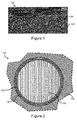
- Figure 1 is cross-sectional micrograph of a CMC component 100 that includes fibers 104 embedded within a matrix 106.
- the matrix 106 may comprise a ceramic material such as SiC, Si 3 N 4 , B 4 C, ZrB 2 , Mo 2 C or the like.
- the matrix 106 may be a silicon containing matrix.
- silicon containing matrix may include or be silicon carbide.
- the silicon containing matrix may include other phases and/or elements other than silicon carbide, but the major phase may be silicon carbide.
- the silicon containing matrix may include residual silicon metal.
- the fibers 104 that are embedded within the matrix 106 may comprise a refractory ceramic such as SiC, Si 3 N 4 , or the like.
- the fibers 104 may include silicon containing refractory fibers such as silicon carbide fibers.
- the silicon carbide fibers may include other phases and/or elements other than silicon carbide, but the major phase may be silicon carbide.
- the silicon carbide fibers may include additional elements other than silicon and carbon to tailor the properties of the silicon carbide fibers.
- Each of the fibers may be a single fiber or filament or a bundle or tow of fibers or filaments.
- the fibers may be a plurality of two-dimensional weaved sheets of fibers stacked or a three-dimensional weave of fibers.
- Figure 2 is a schematic of a cross-sectional view of a portion of an example CMC component 100.
- the fibers 104 may include one or more layers or coatings 108.
- the layer(s) 108 may be formed on the fibers 104 such that the layer(s) 108 are sandwiched between the fibers 104 and the matrix 106.
- the layer(s) 108 may include a silicon carbide layer and/or a boron nitride layer.
- a boron nitride layer may be sandwiched between the fibers 104 and a silicon carbide layer.
- the silicon carbide layer may be distinct from or separate from the silicon containing matrix 106.
- the CMC component 100 further includes a silicide layer 102 sandwiched between the fibers 104 and the matrix 106.
- the fibers 104 include the layer(s) 108
- the layer(s) 108 may be sandwiched between the fibers 104 and the silicide layer 102.
- the major phase of the silicide layer 102 may be a silicide.
- the silicide may include a refractory metal element.
- the refractory metal element may include molybdenum, tungsten, tantalum or a combination thereof.
- the silicide may be molybdenum silicide, tungsten silicide, tantalum silicide or a combination thereof.
- the silicide layer 102 may form a chemical barrier between the fiber 104 and the matrix 106.
- the silicide layer 102 may restrict or prevent chemical interaction between the matrix 106 and the fibers 104.
- the fibers 104 may include one or more layers 108.
- the layers 108 may include one or more elements that may chemically interact or react with one or more elements or phases of the matrix 106 such as residual silicon metal.
- the silicide layer 102 may substantially restrict such chemical interactions or reactions between the matrix 106 and the fibers 104.
- the silicide layer 102 may restrict or substantially prevent diffusion or migration of elements between the fibers 104 and the matrix 106.
- the silicide layer 102 may be chemically stable at elevated temperatures (e.g., greater than about 1500 °C). Thus, the silicide layer 102 may not substantially react with or diffuse into the matrix 106, and the matrix 106 may include substantially zero of the refractory metal element of the silicide.
- the matrix 106 may include a refractory metal element that is the same as the refractory metal element of the silicide layer 102 to tailor the properties of the matrix 106; however, the refractory metal element of the silicide layer 102 may not substantially diffuse into the matrix 106 resulting in a change in composition of the matrix 106.
- the silicide layer 108 may have a thickness of about 0.1 ⁇ m to about 5 ⁇ m. Furthermore, the silicide layer 108 may cover substantially all surfaces of the fibers 104.
- Figure 3 is an example method 200 of forming a ceramic matrix composite.
- the method 200 may include infiltrating a fluid comprising a refractory metal element containing compound into a fiber preform.
- the fiber preform may include refractory fibers such as ceramic fibers, as described above.
- the ceramic fibers may include silicon containing refractory fibers such as silicon carbide.
- the silicon containing refractory fibers may further include one or more distinct layers, also as described above.
- the silicon containing refractory fibers may include a silicon carbide fiber with a silicon carbide layer that surrounds the silicon carbide fiber.
- the silicon containing refractory fibers may further include a layer of boron nitride sandwiched between the silicon carbide fiber and the silicon carbide layer.
- Each of the fibers may be a single fiber or filament or a bundle or tow of fibers or filaments.
- the fiber preform may be formed from stacking a plurality of weaved sheets of refractory fibers or the fiber preform may be formed from a three-dimensional weave of refractory fibers.
- the fiber preform may have voids or porosity between the fibers that may be infiltrated with the fluid such as through chemical vapor infiltration (CVI).
- the fluid may include the refractory metal element containing compound.
- the fluid may be a gas or liquid.
- the refractory metal element containing compound may be in a gas state during infiltration.
- the fluid may include additional components to facilitate infiltration of refractory metal element containing compound.
- the fluid may include an inert gas such as argon.
- the refractory metal element containing compound includes a least one refractory metal element.
- the refractory metal element may include molybdenum, tungsten, tantalum or a combination thereof.
- the refractory metal element containing compound may include molybdenum chloride, tungsten chloride, tantalum chloride or a combination thereof.
- Other example refractory metal element containing compounds may include precursors from the carbonyl family.
- molybdenum chloride molybdenum chloride may be formed by passing a reactive chlorine containing gas through a molybdenum sponge.
- the refractory metal element containing compound may be infiltrated into the preform by surrounding the fiber preform with the refractory metal element containing compound.
- the fluid may be a gas and have a pressure of about 1 Torr to about 20 Torr.
- the infiltration may occur within a hermetically sealed chamber in order to control the environment during infiltration. For example, a negative pressure or vacuum environment may be created within the chamber followed by introduction of the refractory metal element containing compound into the chamber.
- the method 200 may include depositing the refractory metal element from the refractory metal element containing compound onto the fibers of the fiber preform.
- a reducing constituent may be put into chemical interaction with the refractory metal element containing compound to separate the refractory metal element from the refractory metal element containing compound.
- the reducing constituent may include hydrogen.
- the refractory metal element may deposit onto the fibers.
- the refractory metal element may form a refractory metal phase on the fibers.
- the refractory metal element may include molybdenum, tungsten, tantalum or a combination thereof.
- the refractory metal may include molybdenum metal, tungsten metal, tantalum metal or a combination thereof.
- the gas that is infiltrated into the perform may include hydrogen, and in the example of molybdenum, the method may include chemically interacting the hydrogen with molybdenum chloride to deposit the molybdenum.
- the fiber preform may be infiltrated with a slurry.
- the slurry may include particles such as silicon carbide, carbon or a combination thereof.
- the slurry may include substantially zero amount of the refractory metal element.
- the slurry may include less than about 1 % by weight of the refractory metal element.
- the slurry may alternatively include particles that comprise a refractory metal element.
- the slurry may include a liquid such as water in which the particles are suspended within. After infiltration of the slurry into the fiber preform, the liquid of the slurry may be removed by evaporation of the liquid.
- the method 200 may include forming, from the refractory metal element deposited onto the fibers, a refractory metal silicide on the fibers.
- the silicide may include MoSi 2 , WSi 2 , TaSi 2 or a combination thereof. Forming the refractory metal silicide on the fibers may be done subsequent to or prior to infiltrating the fiber preform with the slurry.
- the method of forming the CMC may include melt infiltrating the fiber preform with a molten silicon containing metal or alloy to form the ceramic matrix composite after the slurry infiltration.
- the molten silicon may have a majority constituent being silicon.
- the melt infiltrating may be performed after the refractory metal has been formed in the fiber preform.
- the molten silicon may form silicon carbide with carbon in the fiber preform such as with carbon particles from the slurry.
- the molten silicon and the refractory metal may together further form the silicide.
- at least some of the refractory metal may form a silicide as a result the melt infiltration.
- the refractory silicide may be formed prior to melt infiltration. After the refractory metal has been deposited onto the fibers, silicon in a gas or vapor state may be infiltrated into the preform. The silicon vapor may react with the refractory metal to form the silicide. The formation of the silicide may be done prior to or subsequent to infiltration of the slurry.
- a refractory metal carbide may be formed from the deposited refractory metal element prior to forming the refractory metal silicide.
- the refractory metal may react with carbon to form the refractory metal carbide.
- the refractory metal carbide may be formed by exposing the refractory metal element to a hydrocarbon atmosphere. After forming the refractory metal carbide, a molten silicon containing metal or alloy may be infiltrated into the fiber preform to convert the refractory metal carbide to the refractory metal silicide.
- the CMC may have less silicon metal than a CMC that does not include the refractory metal element.
- the CMC may have at least about 5% by volume less silicon metal than a CMC would have without use of the refractory precursor to form the CMC.
- the CMC with the refractory metal element may have less than about 5% by volume residual porosity.
Landscapes
- Chemical & Material Sciences (AREA)
- Engineering & Computer Science (AREA)
- Ceramic Engineering (AREA)
- Manufacturing & Machinery (AREA)
- Organic Chemistry (AREA)
- Materials Engineering (AREA)
- Structural Engineering (AREA)
- Inorganic Chemistry (AREA)
- Chemical Kinetics & Catalysis (AREA)
- General Chemical & Material Sciences (AREA)
- Mechanical Engineering (AREA)
- Metallurgy (AREA)
- Ceramic Products (AREA)
Abstract
Description
- The present disclosure relates generally to gas turbine engines, and more specifically to ceramic matrix composite components.
- Gas turbine engine components are exposed to high temperature environments with an increasing demand for even higher temperatures. Economic and environmental concerns relating to the reduction of emissions and the increase of efficiency are driving the demand for higher gas turbine operating temperatures. In order to meet these demands, temperature capability of the components in hot sections such as blades, vanes, blade tracks, seal segments and combustor liners may be increased.
- Ceramic matrix composites (CMCs) may be a candidate for inclusion in the hot sections where higher gas turbine engine operating temperatures are required. One benefit of CMC engine components is the high-temperature mechanical, physical, and chemical properties of the CMCs which allow the gas turbine engines to operate at higher temperatures than current engines.
- One possible method of manufacturing dense CMC bodies may include infiltration of a porous, rigidized fiber preform. The method may involve the infiltration of silicon carbide (SiC) particulate filled slurry. The silicon carbide from the slurry may reduce the volume fraction of remaining porosity. Liquid silicon may then be infiltrated into the remaining porosity to form a dense CMC body.
- The present disclosure may comprise one or more of the following features and combinations thereof.
- According to an aspect of the present disclosure, a ceramic matrix composite component may include a silicon containing matrix and refractory fibers embedded within the silicon containing matrix. The ceramic matrix composite component may further include a silicide layer sandwiched between the silicon containing matrix and the refractory fibers.
- The silicide may comprise a refractory metal element.
- The refractory metal element may comprise molybdenum, tungsten, tantalum or a combination thereof.
- The silicon containing matrix may comprise substantially zero of the refractory metal element of the silicide.
- The silicide may comprise molybdenum silicide.
- The silicide layer may comprise a thickness of about 0.1 µm to about 5 µm.
- The refractory fibers may comprise silicon carbide fibers.
- The silicon carbide fibers may comprise a silicon carbide coating.
- The silicide layer may substantially restrict chemical interaction between the silicon carbide fibers and the silicon containing matrix.
- According to another aspect of the present disclosure, a method of forming a ceramic matrix composite may include infiltrating a fluid that includes a refractory metal element containing compound into a fiber preform that includes fibers. The method may further include depositing the refractory metal element from the refractory metal element containing compound onto the fibers and forming, from the refractory metal element deposited onto the fibers, a refractory metal silicide.
- The refractory metal element may comprise molybdenum, tungsten, tantalum or a combination thereof.
- The refractory metal element containing compound may comprise molybdenum chloride.
- Depositing the refractory metal element may comprise forming a refractory metal layer comprising the refractory metal element.
- Forming the refractory metal silicide may comprise exposing the refractory metal element to a silicon vapor.
- The method may further comprise infiltrating the fiber preform with a slurry comprising silicon carbide.
- The method may further comprise melt infiltrating the fiber preform with a molten silicon containing metal or alloy after infiltrating the fiber preform with the slurry.
- The refractory metal silicide may substantially restrict chemical diffusion between the fibers and a silicon containing matrix formed as a result of the melt infiltrating.
- The method may further comprise: infiltrating the fiber preform with a slurry comprising silicon carbide after the depositing the refractory metal element; and melt infiltrating the fiber preform with a molten silicon containing metal or alloy, wherein silicon from the silicon containing metal or alloy and the refractory metal element form at least a portion of the refractory metal silicide.
- The method may further comprise forming a refractory metal carbide from the refractory metal element deposited from the refractory metal containing compound prior to forming the refractory metal silicide.
- The method may further comprise melt infiltrating the fiber preform with a molten silicon containing metal or alloy to convert the refractory metal carbide to the refractory metal silicide.
- The method may further comprise depositing a silicon carbide coating onto the fibers prior to depositing the refractory metal element.
- These and other features of the present disclosure will become more apparent from the following description of the illustrative embodiments.
-
-
Figure 1 is a cross-sectional micrograph of a CMC that includes SiC fibers embedded within a SiC matrix; -
Figure 2 is a schematic cross-sectional view of a portion, a single fiber embedded within a matrix, of an example CMC component that includes a silicide layer sandwiched between the fibers and the matrix; and -
Figure 3 is a flowchart of an example method of forming a CMC that includes a silicide layer between the fibers and the matrix. - For the purposes of promoting an understanding of the principles of the disclosure, reference will now be made to a number of illustrative embodiments illustrated in the drawings and specific language will be used to describe the same.
- Described herein are CMC components and methods of manufacturing CMC components that include a silicide layer between a matrix and fibers embedded within the matrix. The silicide layer may restrict or prevent chemical interaction between the matrix and the fibers. For example, the fibers may include one or more layers that include one or more elements that may chemically interact with one or more elements of the matrix to form dissimilar compounds that are different from the matrix compounds. The dissimilar compounds may adversely affect the mechanical properties of the CMC, and the silicide layer may restrict formation of such dissimilar compounds.
-
Figure 1 is cross-sectional micrograph of aCMC component 100 that includesfibers 104 embedded within amatrix 106. Thematrix 106 may comprise a ceramic material such as SiC, Si3N4, B4C, ZrB2, Mo2C or the like. In some examples, thematrix 106 may be a silicon containing matrix. For example, silicon containing matrix may include or be silicon carbide. The silicon containing matrix may include other phases and/or elements other than silicon carbide, but the major phase may be silicon carbide. For example, the silicon containing matrix may include residual silicon metal. - The
fibers 104 that are embedded within thematrix 106 may comprise a refractory ceramic such as SiC, Si3N4, or the like. In some examples, thefibers 104 may include silicon containing refractory fibers such as silicon carbide fibers. The silicon carbide fibers may include other phases and/or elements other than silicon carbide, but the major phase may be silicon carbide. For example, the silicon carbide fibers may include additional elements other than silicon and carbon to tailor the properties of the silicon carbide fibers. Each of the fibers may be a single fiber or filament or a bundle or tow of fibers or filaments. Furthermore, the fibers may be a plurality of two-dimensional weaved sheets of fibers stacked or a three-dimensional weave of fibers. -
Figure 2 is a schematic of a cross-sectional view of a portion of anexample CMC component 100. In particular,Figure 2 illustrates a cross-section through asingle fiber 104 and the surroundingmatrix 106. Thefibers 104 may include one or more layers orcoatings 108. The layer(s) 108 may be formed on thefibers 104 such that the layer(s) 108 are sandwiched between thefibers 104 and thematrix 106. The layer(s) 108 may include a silicon carbide layer and/or a boron nitride layer. For example, a boron nitride layer may be sandwiched between thefibers 104 and a silicon carbide layer. The silicon carbide layer may be distinct from or separate from thesilicon containing matrix 106. - The
CMC component 100 further includes asilicide layer 102 sandwiched between thefibers 104 and thematrix 106. When thefibers 104 include the layer(s) 108, the layer(s) 108 may be sandwiched between thefibers 104 and thesilicide layer 102. The major phase of thesilicide layer 102 may be a silicide. The silicide may include a refractory metal element. For example, the refractory metal element may include molybdenum, tungsten, tantalum or a combination thereof. Thus, the silicide may be molybdenum silicide, tungsten silicide, tantalum silicide or a combination thereof. Thesilicide layer 102 may form a chemical barrier between thefiber 104 and thematrix 106. For example, thesilicide layer 102 may restrict or prevent chemical interaction between thematrix 106 and thefibers 104. As described above, thefibers 104 may include one ormore layers 108. Thelayers 108 may include one or more elements that may chemically interact or react with one or more elements or phases of thematrix 106 such as residual silicon metal. Thesilicide layer 102 may substantially restrict such chemical interactions or reactions between thematrix 106 and thefibers 104. For example, thesilicide layer 102 may restrict or substantially prevent diffusion or migration of elements between thefibers 104 and thematrix 106. Thesilicide layer 102 may be chemically stable at elevated temperatures (e.g., greater than about 1500 °C). Thus, thesilicide layer 102 may not substantially react with or diffuse into thematrix 106, and thematrix 106 may include substantially zero of the refractory metal element of the silicide. Thematrix 106 may include a refractory metal element that is the same as the refractory metal element of thesilicide layer 102 to tailor the properties of thematrix 106; however, the refractory metal element of thesilicide layer 102 may not substantially diffuse into thematrix 106 resulting in a change in composition of thematrix 106. Thesilicide layer 108 may have a thickness of about 0.1 µm to about 5 µm. Furthermore, thesilicide layer 108 may cover substantially all surfaces of thefibers 104. -
Figure 3 is anexample method 200 of forming a ceramic matrix composite. As shown byoperational block 202, themethod 200 may include infiltrating a fluid comprising a refractory metal element containing compound into a fiber preform. The fiber preform may include refractory fibers such as ceramic fibers, as described above. For example, the ceramic fibers may include silicon containing refractory fibers such as silicon carbide. The silicon containing refractory fibers may further include one or more distinct layers, also as described above. For example, the silicon containing refractory fibers may include a silicon carbide fiber with a silicon carbide layer that surrounds the silicon carbide fiber. The silicon containing refractory fibers may further include a layer of boron nitride sandwiched between the silicon carbide fiber and the silicon carbide layer. Each of the fibers may be a single fiber or filament or a bundle or tow of fibers or filaments. The fiber preform may be formed from stacking a plurality of weaved sheets of refractory fibers or the fiber preform may be formed from a three-dimensional weave of refractory fibers. - The fiber preform may have voids or porosity between the fibers that may be infiltrated with the fluid such as through chemical vapor infiltration (CVI). The fluid may include the refractory metal element containing compound. The fluid may be a gas or liquid. For example, the refractory metal element containing compound may be in a gas state during infiltration. The fluid may include additional components to facilitate infiltration of refractory metal element containing compound. For example, the fluid may include an inert gas such as argon.
- The refractory metal element containing compound includes a least one refractory metal element. The refractory metal element may include molybdenum, tungsten, tantalum or a combination thereof. The refractory metal element containing compound may include molybdenum chloride, tungsten chloride, tantalum chloride or a combination thereof. Other example refractory metal element containing compounds may include precursors from the carbonyl family. In the example of molybdenum chloride, molybdenum chloride may be formed by passing a reactive chlorine containing gas through a molybdenum sponge.
- The refractory metal element containing compound may be infiltrated into the preform by surrounding the fiber preform with the refractory metal element containing compound. During infiltration, the fluid may be a gas and have a pressure of about 1 Torr to about 20 Torr. The infiltration may occur within a hermetically sealed chamber in order to control the environment during infiltration. For example, a negative pressure or vacuum environment may be created within the chamber followed by introduction of the refractory metal element containing compound into the chamber.
- As shown by
operational block 204, themethod 200 may include depositing the refractory metal element from the refractory metal element containing compound onto the fibers of the fiber preform. A reducing constituent may be put into chemical interaction with the refractory metal element containing compound to separate the refractory metal element from the refractory metal element containing compound. For example, the reducing constituent may include hydrogen. After the refractory metal element is separated from the refractory metal element containing compound, the refractory metal element may deposit onto the fibers. The refractory metal element may form a refractory metal phase on the fibers. As described above, the refractory metal element may include molybdenum, tungsten, tantalum or a combination thereof. Thus, the refractory metal may include molybdenum metal, tungsten metal, tantalum metal or a combination thereof. The gas that is infiltrated into the perform may include hydrogen, and in the example of molybdenum, the method may include chemically interacting the hydrogen with molybdenum chloride to deposit the molybdenum. - Subsequent to depositing the refractory metal element onto the fibers, the fiber preform may be infiltrated with a slurry. The slurry may include particles such as silicon carbide, carbon or a combination thereof. Furthermore, the slurry may include substantially zero amount of the refractory metal element. For example, the slurry may include less than about 1 % by weight of the refractory metal element. However, the slurry may alternatively include particles that comprise a refractory metal element. The slurry may include a liquid such as water in which the particles are suspended within. After infiltration of the slurry into the fiber preform, the liquid of the slurry may be removed by evaporation of the liquid.
- As shown by
operational block 206, themethod 200 may include forming, from the refractory metal element deposited onto the fibers, a refractory metal silicide on the fibers. The silicide may include MoSi2, WSi2, TaSi2 or a combination thereof. Forming the refractory metal silicide on the fibers may be done subsequent to or prior to infiltrating the fiber preform with the slurry. - In one example, the method of forming the CMC may include melt infiltrating the fiber preform with a molten silicon containing metal or alloy to form the ceramic matrix composite after the slurry infiltration. The molten silicon may have a majority constituent being silicon. The melt infiltrating may be performed after the refractory metal has been formed in the fiber preform. The molten silicon may form silicon carbide with carbon in the fiber preform such as with carbon particles from the slurry. The molten silicon and the refractory metal may together further form the silicide. Thus, at least some of the refractory metal may form a silicide as a result the melt infiltration.
- In another example, the refractory silicide may be formed prior to melt infiltration. After the refractory metal has been deposited onto the fibers, silicon in a gas or vapor state may be infiltrated into the preform. The silicon vapor may react with the refractory metal to form the silicide. The formation of the silicide may be done prior to or subsequent to infiltration of the slurry.
- In a further example, a refractory metal carbide may be formed from the deposited refractory metal element prior to forming the refractory metal silicide. The refractory metal may react with carbon to form the refractory metal carbide. For example, the refractory metal carbide may be formed by exposing the refractory metal element to a hydrocarbon atmosphere. After forming the refractory metal carbide, a molten silicon containing metal or alloy may be infiltrated into the fiber preform to convert the refractory metal carbide to the refractory metal silicide.
- Since the refractory metal element may form a refractory metal silicide with silicon metal in the CMC, the CMC may have less silicon metal than a CMC that does not include the refractory metal element. For example, the CMC may have at least about 5% by volume less silicon metal than a CMC would have without use of the refractory precursor to form the CMC. Furthermore, the CMC with the refractory metal element may have less than about 5% by volume residual porosity.
- The following three prophetic examples are provided to demonstrate the benefits of certain embodiments of the disclosed methods. These examples are discussed for illustrative purposes and should not be construed to limit the scope of the disclosed embodiments.
- Example 1. A first method of forming a CMC may include deposition of a molybdenum coating through CVI prior to slurry infiltration. The method may include the following components and steps.
- 1) Following CVI of a SiC layer resulting in rigidization of the porous fiber preform, the fiber preform is coated with molybdenum metal by passing a reactive chlorine containing gas through a heated molybdenum sponge to form molybdenum chloride. The molybdenum chloride is then introduced into a CVI reactor along with hydrogen gas to deposit elemental molybdenum on all surfaces of the fiber preform.
- 2) The fiber preform is then slurry infiltrated with a SiC containing slurry to fill a major percentage of the remaining porosity.
- 3) The fiber preform is then melt infiltrated with molten silicon or alloy to form a stable MoSi2 barrier layer and a dense composite article with less than about 5% residual porosity.
- Example 2. A second method of forming a CMC may include deposition of a molybdenum coating through CVI, then reaction forming molybdenum carbide using a heat treatment in a hydrocarbon atmosphere, then slurry infiltrating the fiber preform, and then melt infiltrating the fiber preform with a molten silicon metal or alloy to form a molybdenum disilicide silicon layer as well as additional silicon carbide to further reduce the amount of residual silicon metal in the component. The method may include the following components and steps.
- 1) Following CVI of a SiC layer resulting in rigidization of the porous fiber preform, the fiber preform is coated with molybdenum metal by passing a reactive chlorine containing gas through a heated molybdenum sponge to form molybdenum chloride. The molybdenum chloride is then introduced into a CVI reactor along with hydrogen gas to deposit elemental molybdenum on all surfaces of the fiber preform.
- 2) Heat treating the fiber preform in methane at about 1000 °C to convert the molybdenum to Mo2C.
- 3) The fiber preform is then slurry infiltrated with a SiC containing slurry to fill a major percentage of the remaining porosity.
- 4) The body is melt infiltrated with molten silicon metal or alloy to form a stable MoSi2 barrier layer and additional silicon carbide resulting in a dense composite article with less than about 5% residual porosity and a lower residual silicon metal content.
- Example 3. A third example method of forming a CMC may include depositing molybdenum metal followed by vapor phase siliciding the molybdenum metal prior to slurry infiltration to form the molybdenum silicide layer. The method may include the following components and steps.
- 1) Depositing molybdenum into the fiber preform and onto the fibers. Forming molybdenum silicide such as MoSi2, Mo5Si3 or combination thereof by introducing silicon vapor into the fiber preform.
- 2) Slurry infiltrating the fiber preform with a SiC slurry to further reduce the residual porosity in the body.
- 3) Melt infiltrating the fiber preform with molten silicon metal or alloy. Converting Mo5Si3 (if present) to MoSi2 to form a stable MoSi2 layer. A dense composite article with less than about 5% residual porosity is formed.
- While the disclosure has been illustrated and described in detail in the foregoing drawings and description, the same is to be considered as exemplary and not restrictive in character, it being understood that only illustrative embodiments thereof have been shown and described and that all changes and modifications that come within the spirit of the disclosure are desired to be protected.
Claims (15)
- A ceramic matrix composite component comprising:a silicon containing matrix;refractory fibers embedded within the silicon containing matrix; anda silicide layer sandwiched between the silicon containing matrix and the refractory fibers.
- The ceramic matrix composite component of Claim 1, wherein the silicide comprises a refractory metal element.
- The ceramic matrix composite component of Claim 2, wherein the refractory metal element comprises molybdenum, tungsten, tantalum or a combination thereof.
- The ceramic matrix composite component of Claim 2, wherein the silicon containing matrix comprises substantially zero of the refractory metal element of the silicide.
- The ceramic matrix composite component of any of the preceding Claims, wherein the silicide layer comprises a thickness of about 0.1 µm to about 5 µm.
- The ceramic matrix composite component of any of the preceding Claims, wherein the refractory fibers comprise silicon carbide fibers.
- The ceramic matrix composite component of Claim 6, wherein the silicon carbide fibers comprise a silicon carbide coating.
- The ceramic matrix composite component of any of the preceding Claims, wherein the silicide layer substantially restricts chemical interaction between the silicon carbide fibers and the silicon containing matrix.
- A method of forming a ceramic matrix composite comprising:infiltrating a fluid comprising a refractory metal element containing compound into a fiber preform comprising fibers;depositing the refractory metal element from the refractory metal element containing compound onto the fibers; andforming, from the refractory metal element deposited onto the fibers, a refractory metal silicide.
- The method of Claim 9, wherein depositing the refractory metal element comprises forming a refractory metal layer comprising the refractory metal element.
- The method of Claim 9, wherein forming the refractory metal silicide comprises exposing the refractory metal element to a silicon vapor.
- The method of any of Claims 9 to 11, further comprising infiltrating the fiber preform with a slurry comprising silicon carbide.
- The method of Claim 12, further comprising melt infiltrating the fiber preform with a molten silicon containing metal or alloy after infiltrating the fiber preform with the slurry.
- The method of Claim 9, further comprising:infiltrating the fiber preform with a slurry comprising silicon carbide after the depositing the refractory metal element; andmelt infiltrating the fiber preform with a molten silicon containing metal or alloy,wherein silicon from the silicon containing metal or alloy and the refractory metal element form at least a portion of the refractory metal silicide.
- The method of Claim 9, further comprising forming a refractory metal carbide from the refractory metal element deposited from the refractory metal containing compound prior to forming the refractory metal silicide.
Applications Claiming Priority (1)
| Application Number | Priority Date | Filing Date | Title |
|---|---|---|---|
| US201562204256P | 2015-08-12 | 2015-08-12 |
Publications (2)
| Publication Number | Publication Date |
|---|---|
| EP3130575A2 true EP3130575A2 (en) | 2017-02-15 |
| EP3130575A3 EP3130575A3 (en) | 2017-05-03 |
Family
ID=56842626
Family Applications (1)
| Application Number | Title | Priority Date | Filing Date |
|---|---|---|---|
| EP16183174.8A Withdrawn EP3130575A3 (en) | 2015-08-12 | 2016-08-08 | Ceramic matrix composite having a silicide layer |
Country Status (2)
| Country | Link |
|---|---|
| US (1) | US10233126B2 (en) |
| EP (1) | EP3130575A3 (en) |
Cited By (2)
| Publication number | Priority date | Publication date | Assignee | Title |
|---|---|---|---|---|
| US20210002766A1 (en) * | 2017-08-28 | 2021-01-07 | Raytheon Technologies Corporation | Method for fabricating ceramic matrix composite components |
| CN113481479A (en) * | 2021-07-02 | 2021-10-08 | 吉林大学 | SiC fiber reinforced refractory alloy composite material and preparation method and application thereof |
Families Citing this family (2)
| Publication number | Priority date | Publication date | Assignee | Title |
|---|---|---|---|---|
| US11046620B2 (en) * | 2018-10-18 | 2021-06-29 | Rolls-Royce Corporation | Method of processing a ceramic matrix composite (CMC) component |
| US10752556B2 (en) | 2018-10-18 | 2020-08-25 | Rolls-Royce High Temperature Composites Inc. | Method of processing a ceramic matrix composite (CMC) component |
Family Cites Families (22)
| Publication number | Priority date | Publication date | Assignee | Title |
|---|---|---|---|---|
| US4582720A (en) * | 1982-09-20 | 1986-04-15 | Semiconductor Energy Laboratory Co., Ltd. | Method and apparatus for forming non-single-crystal layer |
| US5079195A (en) | 1988-01-15 | 1992-01-07 | Massachusetts Institute Of Technology | Method of preparing refractory silicon carbide composites and coatings |
| US5244748A (en) | 1989-01-27 | 1993-09-14 | Technical Research Associates, Inc. | Metal matrix coated fiber composites and the methods of manufacturing such composites |
| US5149514A (en) | 1989-04-04 | 1992-09-22 | Sri International | Low temperature method of forming materials using one or more metal reactants and a halogen-containing reactant to form one or more reactive intermediates |
| EP0519641A1 (en) | 1991-06-17 | 1992-12-23 | General Electric Company | Silicon carbide composite with coated fiber reinforcement and method of forming |
| US5834115A (en) | 1995-05-02 | 1998-11-10 | Technical Research Associates, Inc. | Metal and carbonaceous materials composites |
| US5914156A (en) | 1995-05-02 | 1999-06-22 | Technical Research Associates, Inc. | Method for coating a carbonaceous material with a molybdenum carbide coating |
| US5939216A (en) * | 1995-05-10 | 1999-08-17 | Kabushiki Kaisha Toshiba | Fiber reinforced ceramic matrix composite and method of manufacturing the same |
| US5855955A (en) * | 1995-06-07 | 1999-01-05 | Lanxide Technology Company L.P. | Method for making self-supporting composite bodies |
| US5955391A (en) | 1996-03-29 | 1999-09-21 | Kabushiki Kaisha Toshiba | Ceramic matrix composite and method of manufacturing the same |
| EP0798280B1 (en) * | 1996-03-29 | 2001-09-12 | Kabushiki Kaisha Toshiba | Ceramic matrix composite and method of manufacturing the same |
| US6024898A (en) | 1996-12-30 | 2000-02-15 | General Electric Company | Article and method for making complex shaped preform and silicon carbide composite by melt infiltration |
| US6793873B2 (en) | 1997-03-21 | 2004-09-21 | Daimlerchrysler Ag | Melted-infiltrated fiber-reinforced composite ceramic |
| US5952046A (en) | 1998-01-21 | 1999-09-14 | Advanced Technology Materials, Inc. | Method for liquid delivery chemical vapor deposition of carbide films on substrates |
| US6503572B1 (en) | 1999-07-23 | 2003-01-07 | M Cubed Technologies, Inc. | Silicon carbide composites and methods for making same |
| US7658781B1 (en) | 1999-07-23 | 2010-02-09 | Marlene Rossing, legal representative | Silicon-containing composite bodies, and methods for making same |
| US6979490B2 (en) * | 2001-01-16 | 2005-12-27 | Steffier Wayne S | Fiber-reinforced ceramic composite material comprising a matrix with a nanolayered microstructure |
| US6783824B2 (en) * | 2001-01-25 | 2004-08-31 | Hyper-Therm High-Temperature Composites, Inc. | Actively-cooled fiber-reinforced ceramic matrix composite rocket propulsion thrust chamber and method of producing the same |
| US6726444B2 (en) * | 2002-03-18 | 2004-04-27 | General Electric Company | Hybrid high temperature articles and method of making |
| US7951459B2 (en) | 2006-11-21 | 2011-05-31 | United Technologies Corporation | Oxidation resistant coatings, processes for coating articles, and their coated articles |
| US20130167374A1 (en) * | 2011-12-29 | 2013-07-04 | General Electric Company | Process of producing ceramic matrix composites and ceramic matrix composites formed thereby |
| US20140342168A1 (en) * | 2013-05-17 | 2014-11-20 | General Electric Company | Article for high temperature service |
-
2016
- 2016-08-05 US US15/229,786 patent/US10233126B2/en active Active
- 2016-08-08 EP EP16183174.8A patent/EP3130575A3/en not_active Withdrawn
Non-Patent Citations (1)
| Title |
|---|
| None |
Cited By (4)
| Publication number | Priority date | Publication date | Assignee | Title |
|---|---|---|---|---|
| US20210002766A1 (en) * | 2017-08-28 | 2021-01-07 | Raytheon Technologies Corporation | Method for fabricating ceramic matrix composite components |
| US11597686B2 (en) * | 2017-08-28 | 2023-03-07 | Raytheon Technologies Corporation | Method for fabricating ceramic matrix composite components |
| CN113481479A (en) * | 2021-07-02 | 2021-10-08 | 吉林大学 | SiC fiber reinforced refractory alloy composite material and preparation method and application thereof |
| CN113481479B (en) * | 2021-07-02 | 2022-08-05 | 吉林大学 | SiC fiber reinforced refractory alloy composite material and preparation method and application thereof |
Also Published As
| Publication number | Publication date |
|---|---|
| EP3130575A3 (en) | 2017-05-03 |
| US20170044070A1 (en) | 2017-02-16 |
| US10233126B2 (en) | 2019-03-19 |
Similar Documents
| Publication | Publication Date | Title |
|---|---|---|
| US10683764B2 (en) | Modified atmosphere melt infiltration | |
| US20250026691A1 (en) | Method for fabricating a ceramic material | |
| EP3070073B1 (en) | Diffusion barrier layers for ceramic matrix composites | |
| US10458653B2 (en) | Machinable CMC insert | |
| US5945166A (en) | Method for forming fiber reinforced composite bodies with graded composition and stress zones | |
| EP1867619B1 (en) | Method of coating a ceramic based felt | |
| EP2578556B1 (en) | Method and ceramic component | |
| US11046615B2 (en) | Self-healing matrix for a ceramic composite | |
| US10233126B2 (en) | Forming a ceramic matrix composite having a silicide layer | |
| US8980434B2 (en) | Mo—Si—B—based coatings for ceramic base substrates | |
| US11702369B2 (en) | Method of fabricating a ceramic composite | |
| US20230219858A1 (en) | Method for fabricating ceramic matrix composite components | |
| US9593049B2 (en) | Method for incorporating refractory metal element into ceramic matrix composite | |
| EP2933353B1 (en) | Method for producing fiber-reinforced composites | |
| EP4019664A1 (en) | Method and article for metal vapor infiltration of cmc parts | |
| EP3046889B1 (en) | Method of fabricating a ceramic article | |
| EP4306498A1 (en) | High entropy ceramic for protection or multi-layer ifc | |
| CN110191870A (en) | Use the infiltration method of SiGa and/or Siln alloy | |
| JP3031853B2 (en) | Heat and oxidation resistant carbon materials | |
| Tsirlin et al. | Strength and Oxidation Resistance of SiC Fibers Coated with Various Si‐Containing Compositions | |
| Perepezko et al. | Mo-Si-B-Based Coatings for Ceramic Base Substrates | |
| Shemaev et al. | WITH VARIOUS Si-CONTAINING COMPOSITIONS |
Legal Events
| Date | Code | Title | Description |
|---|---|---|---|
| PUAI | Public reference made under article 153(3) epc to a published international application that has entered the european phase |
Free format text: ORIGINAL CODE: 0009012 |
|
| STAA | Information on the status of an ep patent application or granted ep patent |
Free format text: STATUS: THE APPLICATION HAS BEEN PUBLISHED |
|
| AK | Designated contracting states |
Kind code of ref document: A2 Designated state(s): AL AT BE BG CH CY CZ DE DK EE ES FI FR GB GR HR HU IE IS IT LI LT LU LV MC MK MT NL NO PL PT RO RS SE SI SK SM TR |
|
| AX | Request for extension of the european patent |
Extension state: BA ME |
|
| PUAL | Search report despatched |
Free format text: ORIGINAL CODE: 0009013 |
|
| AK | Designated contracting states |
Kind code of ref document: A3 Designated state(s): AL AT BE BG CH CY CZ DE DK EE ES FI FR GB GR HR HU IE IS IT LI LT LU LV MC MK MT NL NO PL PT RO RS SE SI SK SM TR |
|
| AX | Request for extension of the european patent |
Extension state: BA ME |
|
| RIC1 | Information provided on ipc code assigned before grant |
Ipc: C04B 35/80 20060101ALI20170325BHEP Ipc: C04B 35/628 20060101ALI20170325BHEP Ipc: C04B 35/565 20060101AFI20170325BHEP |
|
| STAA | Information on the status of an ep patent application or granted ep patent |
Free format text: STATUS: THE APPLICATION IS DEEMED TO BE WITHDRAWN |
|
| 18D | Application deemed to be withdrawn |
Effective date: 20171104 |