EP3130539A1 - Heat exchanger for a gas turbine engine propulsion system - Google Patents
Heat exchanger for a gas turbine engine propulsion system Download PDFInfo
- Publication number
- EP3130539A1 EP3130539A1 EP16180259.0A EP16180259A EP3130539A1 EP 3130539 A1 EP3130539 A1 EP 3130539A1 EP 16180259 A EP16180259 A EP 16180259A EP 3130539 A1 EP3130539 A1 EP 3130539A1
- Authority
- EP
- European Patent Office
- Prior art keywords
- duct
- heat exchanger
- bypass air
- diverter valve
- gas turbine
- Prior art date
- Legal status (The legal status is an assumption and is not a legal conclusion. Google has not performed a legal analysis and makes no representation as to the accuracy of the status listed.)
- Granted
Links
Images


Classifications
-
- F—MECHANICAL ENGINEERING; LIGHTING; HEATING; WEAPONS; BLASTING
- F02—COMBUSTION ENGINES; HOT-GAS OR COMBUSTION-PRODUCT ENGINE PLANTS
- F02C—GAS-TURBINE PLANTS; AIR INTAKES FOR JET-PROPULSION PLANTS; CONTROLLING FUEL SUPPLY IN AIR-BREATHING JET-PROPULSION PLANTS
- F02C7/00—Features, components parts, details or accessories, not provided for in, or of interest apart form groups F02C1/00 - F02C6/00; Air intakes for jet-propulsion plants
- F02C7/12—Cooling of plants
- F02C7/16—Cooling of plants characterised by cooling medium
- F02C7/18—Cooling of plants characterised by cooling medium the medium being gaseous, e.g. air
- F02C7/185—Cooling means for reducing the temperature of the cooling air or gas
-
- B—PERFORMING OPERATIONS; TRANSPORTING
- B64—AIRCRAFT; AVIATION; COSMONAUTICS
- B64D—EQUIPMENT FOR FITTING IN OR TO AIRCRAFT; FLIGHT SUITS; PARACHUTES; ARRANGEMENT OR MOUNTING OF POWER PLANTS OR PROPULSION TRANSMISSIONS IN AIRCRAFT
- B64D33/00—Arrangement in aircraft of power plant parts or auxiliaries not otherwise provided for
- B64D33/08—Arrangement in aircraft of power plant parts or auxiliaries not otherwise provided for of power plant cooling systems
- B64D33/10—Radiator arrangement
-
- F—MECHANICAL ENGINEERING; LIGHTING; HEATING; WEAPONS; BLASTING
- F01—MACHINES OR ENGINES IN GENERAL; ENGINE PLANTS IN GENERAL; STEAM ENGINES
- F01D—NON-POSITIVE DISPLACEMENT MACHINES OR ENGINES, e.g. STEAM TURBINES
- F01D25/00—Component parts, details, or accessories, not provided for in, or of interest apart from, other groups
- F01D25/08—Cooling; Heating; Heat-insulation
- F01D25/12—Cooling
-
- F—MECHANICAL ENGINEERING; LIGHTING; HEATING; WEAPONS; BLASTING
- F02—COMBUSTION ENGINES; HOT-GAS OR COMBUSTION-PRODUCT ENGINE PLANTS
- F02C—GAS-TURBINE PLANTS; AIR INTAKES FOR JET-PROPULSION PLANTS; CONTROLLING FUEL SUPPLY IN AIR-BREATHING JET-PROPULSION PLANTS
- F02C6/00—Plural gas-turbine plants; Combinations of gas-turbine plants with other apparatus; Adaptations of gas-turbine plants for special use
- F02C6/04—Gas-turbine plants providing heated or pressurised working fluid for other apparatus, e.g. without mechanical power output
- F02C6/06—Gas-turbine plants providing heated or pressurised working fluid for other apparatus, e.g. without mechanical power output providing compressed gas
- F02C6/08—Gas-turbine plants providing heated or pressurised working fluid for other apparatus, e.g. without mechanical power output providing compressed gas the gas being bled from the gas-turbine compressor
-
- F—MECHANICAL ENGINEERING; LIGHTING; HEATING; WEAPONS; BLASTING
- F02—COMBUSTION ENGINES; HOT-GAS OR COMBUSTION-PRODUCT ENGINE PLANTS
- F02C—GAS-TURBINE PLANTS; AIR INTAKES FOR JET-PROPULSION PLANTS; CONTROLLING FUEL SUPPLY IN AIR-BREATHING JET-PROPULSION PLANTS
- F02C7/00—Features, components parts, details or accessories, not provided for in, or of interest apart form groups F02C1/00 - F02C6/00; Air intakes for jet-propulsion plants
- F02C7/12—Cooling of plants
- F02C7/14—Cooling of plants of fluids in the plant, e.g. lubricant or fuel
-
- F—MECHANICAL ENGINEERING; LIGHTING; HEATING; WEAPONS; BLASTING
- F02—COMBUSTION ENGINES; HOT-GAS OR COMBUSTION-PRODUCT ENGINE PLANTS
- F02C—GAS-TURBINE PLANTS; AIR INTAKES FOR JET-PROPULSION PLANTS; CONTROLLING FUEL SUPPLY IN AIR-BREATHING JET-PROPULSION PLANTS
- F02C9/00—Controlling gas-turbine plants; Controlling fuel supply in air- breathing jet-propulsion plants
- F02C9/16—Control of working fluid flow
- F02C9/18—Control of working fluid flow by bleeding, bypassing or acting on variable working fluid interconnections between turbines or compressors or their stages
-
- F—MECHANICAL ENGINEERING; LIGHTING; HEATING; WEAPONS; BLASTING
- F02—COMBUSTION ENGINES; HOT-GAS OR COMBUSTION-PRODUCT ENGINE PLANTS
- F02K—JET-PROPULSION PLANTS
- F02K3/00—Plants including a gas turbine driving a compressor or a ducted fan
- F02K3/02—Plants including a gas turbine driving a compressor or a ducted fan in which part of the working fluid by-passes the turbine and combustion chamber
- F02K3/04—Plants including a gas turbine driving a compressor or a ducted fan in which part of the working fluid by-passes the turbine and combustion chamber the plant including ducted fans, i.e. fans with high volume, low pressure outputs, for augmenting the jet thrust, e.g. of double-flow type
- F02K3/06—Plants including a gas turbine driving a compressor or a ducted fan in which part of the working fluid by-passes the turbine and combustion chamber the plant including ducted fans, i.e. fans with high volume, low pressure outputs, for augmenting the jet thrust, e.g. of double-flow type with front fan
-
- F—MECHANICAL ENGINEERING; LIGHTING; HEATING; WEAPONS; BLASTING
- F02—COMBUSTION ENGINES; HOT-GAS OR COMBUSTION-PRODUCT ENGINE PLANTS
- F02K—JET-PROPULSION PLANTS
- F02K3/00—Plants including a gas turbine driving a compressor or a ducted fan
- F02K3/08—Plants including a gas turbine driving a compressor or a ducted fan with supplementary heating of the working fluid; Control thereof
- F02K3/105—Heating the by-pass flow
- F02K3/115—Heating the by-pass flow by means of indirect heat exchange
-
- Y—GENERAL TAGGING OF NEW TECHNOLOGICAL DEVELOPMENTS; GENERAL TAGGING OF CROSS-SECTIONAL TECHNOLOGIES SPANNING OVER SEVERAL SECTIONS OF THE IPC; TECHNICAL SUBJECTS COVERED BY FORMER USPC CROSS-REFERENCE ART COLLECTIONS [XRACs] AND DIGESTS
- Y02—TECHNOLOGIES OR APPLICATIONS FOR MITIGATION OR ADAPTATION AGAINST CLIMATE CHANGE
- Y02T—CLIMATE CHANGE MITIGATION TECHNOLOGIES RELATED TO TRANSPORTATION
- Y02T50/00—Aeronautics or air transport
- Y02T50/60—Efficient propulsion technologies, e.g. for aircraft
Definitions
- the present disclosure relates generally to propulsion systems, and more specifically to propulsion systems including gas turbine engines.
- Propulsion systems used in some aircraft include gas turbine engines that have an engine core operable to generate thrust for moving the aircraft.
- pressurized air passed through the engine core may be cooled using a cooling unit.
- placement of a cooling unit in the engine core presents a number of drawbacks.
- the present disclosure may comprise one or more of the following features and combinations thereof.
- a propulsion system for an aircraft may include a gas turbine engine and a nacelle.
- the gas turbine engine may include an engine core and a fan coupled to the engine core.
- the fan may be configured to discharge pressurized bypass air that is passed around the engine core.
- the nacelle may surround a portion of the gas turbine engine, and the nacelle may include a strut and a cooling unit housed in the strut.
- the strut may extend away from the gas turbine engine, and the cooling unit may be fluidly coupled to the gas turbine engine to cool fluid or gas from the gas turbine engine and return the cooled fluid or gas to the gas turbine engine.
- the cooling unit may include a duct, a heat exchanger positioned within the duct, and a diverter valve.
- the diverter valve may be movable within the duct from a first position arranged to direct pressurized bypass air moving through the duct into contact with the heat exchanger to a second position arranged to divert pressurized bypass air around the heat exchanger without contacting the heat exchanger.
- the cooling unit may be positioned radially-outward of the engine core and radially-inward of an outer shroud included in the nacelle.
- the duct may include a divider extending along the length of the duct to divide the duct into an outer flow portion and an inner flow portion positioned radially-inward of the outer flow portion.
- the diverter valve may be movable between the first and second positions to control cooling of the fluid or gas from the gas turbine engine.
- the diverter valve may include a first actuator and a plate coupled to the first actuator, and the first actuator may be operable to pivot the plate relative to the duct between the first and second positions.
- the diverter valve may include a second actuator coupled to the plate, and the second actuator may be operable to move the plate relative to the duct between the first and second positions in the event of a failure of the first actuator.
- the heat exchanger may have a core having a face
- pressurized bypass air directed into contact with the heat exchanger by the diverter valve when the diverter valve is in the first position may be conducted by a header included in the duct to the core at an angle to the face that is different from 90 degrees.
- Pressurized bypass air directed into contact with the heat exchanger by the diverter valve when the diverter valve is in the first position may be conducted by the header from an inlet of the duct to the core of the heat exchanger along a forward flow path generally parallel to an aft flow path along which pressurized bypass air is conducted away from the heat exchanger to an outlet of the duct.
- the fan may be configured to discharge pressurized bypass air in a direction having a circumferential component and an axial component at an outlet thereof, and an inlet of the duct may be shaped to open axially and circumferentially to receive the pressurized bypass air discharged from the fan so that the total pressure of the pressurized bypass air is captured by the duct during operation of the propulsion system.
- An outlet of the duct may be shaped to discharge pressurized bypass air in a substantially axial direction only.
- an aircraft may include an airframe, a gas turbine engine, and a nacelle.
- the gas turbine engine and the nacelle may be supported by the airframe.
- the gas turbine engine may include an engine core defining an engine axis and a fan coupled to the engine core.
- the fan may be configured to discharge pressurized bypass air that is passed around the engine core.
- the nacelle may surround a portion of the gas turbine engine, and the nacelle may include a pylon, a strut, and a cooling unit.
- the pylon may be coupled to the airframe, and the strut may be spaced from the pylon and extend outwardly from the gas turbine engine away from the engine axis.
- the cooling unit may be housed in the strut and fluidly coupled to the gas turbine engine to cool fluid or gas from the gas turbine engine.
- the cooling unit may be configured to receive pressurized bypass air from the fan and pass the pressurized bypass air through a heat exchanger included in the cooling unit during operation of the aircraft.
- the pylon may be spaced about 180 degrees from the strut and the cooling unit about the engine axis. Additionally, in some embodiments, the cooling unit may be positioned radially-outward of the engine core and radially-inward of an outer shroud included in the nacelle.
- the cooling unit may include a duct having walls housed in the strut and a diverter valve that is movable within the duct from a first position arranged to direct pressurized bypass air moving through the duct into contact with the heat exchanger to a second position arranged to divert pressurized bypass air around the heat exchanger without contacting the heat exchanger.
- the duct may include a divider extending along the length of the duct to divide the duct into an outer flow portion and an inner flow portion positioned radially-inward of the outer flow portion.
- the diverter valve may include a first actuator and a plate coupled to the first actuator, and the first actuator may be operable to pivot the plate relative to the duct between the first and the second positions.
- the diverter valve may include a second actuator coupled to the plate, and the second actuator may be operable to move the plate relative to the duct between the first and second positions in the event of a failure of the first actuator.
- the heat exchanger may have a core having a face, and pressurized bypass air directed into contact with the heat exchanger by the diverter valve when the diverter valve is in the first position may be conducted by a header included in the duct to the core at an angle to the face that is different from 90 degrees.
- Pressurized bypass air directed into contact with the heat exchanger by the diverter valve when the diverter valve is in the first position may be conducted by the header from an inlet of the duct to the core of the heat exchanger along a forward flow path generally parallel to an aft flow path along which pressurized bypass air is conducted away from the heat exchanger to an outlet of the duct.
- the fan may be configured to discharge pressurized bypass air in a direction having a circumferential component and an axial component at an outlet thereof, and an inlet of the duct may be shaped to open axially and circumferentially to receive the pressurized bypass air discharged from the fan so that the total pressure of the pressurized bypass air is captured by the duct during operation of the aircraft.
- An outlet of the duct may be shaped to discharge pressurized bypass air in a substantially axial direction only
- an illustrative aircraft 10 includes an airframe 12 and a pair of propulsion systems 14, 16 that are coupled to the airframe 12 opposite one another.
- the propulsions systems 14, 16 are substantially identical to one another. In other embodiments, however, the aircraft 10 may include any suitable number of propulsion systems other than the two propulsions systems 14, 16.
- the propulsion system 14 illustratively includes a nacelle 18 and a gas turbine engine 20.
- the nacelle 18 is coupled to the airframe 12, as shown in Fig. 1 , and surrounds at least a portion of the gas turbine engine 20, as best seen in Fig. 2 .
- the gas turbine engine 20 is configured to generate thrust to move the aircraft 10 while being supported in the nacelle 18.
- the nacelle 18 illustratively includes a pylon 22, a strut 24, and a cooling unit 26 as shown in Fig. 2 .
- the pylon 22 is configured to couple to the airframe 12 and extends away from the gas turbine engine 20.
- the strut 24 also extends away from the gas turbine engine 20 and is spaced from the pylon 22 in a circumferential direction indicated by arrow C.
- the cooling unit 26 is housed in the strut 24 and fluidly coupled to the gas turbine engine 20 to cool fluid from the engine 20 and return the cooled fluid to the engine 20.
- the nacelle 18 includes only one strut 24 and one cooling unit 26 housed in the strut 24. In other embodiments, however, the nacelle 18 may include multiple struts 24 that each house one cooling unit 26.
- the gas turbine engine 20 illustratively includes an engine core 28 and a fan 30 that is coupled to the engine core 28 to be driven by the engine core 28 as shown in Fig. 2 .
- the engine core 28 is configured to pass pressurized air therethrough so that the pressurized air flows aftward along an engine axis 32 defined by the engine core 28.
- the fan 30 is configured to discharge pressurized bypass air that is passed around the engine core 28 aftward along the engine axis 32.
- the cooling unit 26 illustratively includes a duct 34, a heat exchanger 36, and a diverter valve 38.
- the heat exchanger 36 and the diverter valve 38 are positioned within the duct 34, and the diverter valve 38 is movable therein from an open position 38a (see Figs. 4-5 ) to a closed position 38b (see Figs. 6-7 ).
- the diverter valve 38 In the open position 38a, the diverter valve 38 directs the bypass air discharged by the fan 30 through the duct 34 and into contact with the heat exchanger 36.
- the diverter valve 38 diverts the bypass air discharged by the fan 30 around the heat exchanger 36 without contacting the heat exchanger 36.
- the cooling unit 26 is therefore configured to selectively pass bypass air through the heat exchanger 36 during operation of the aircraft 10.
- fluid from the engine core 28 passes along a flow path 28F.
- fluid from the engine core 28 passes along the flow path 28F from one component of the engine core 28 through the heat exchanger 36 and is returned to another component of the engine core 28 by the heat exchanger 36.
- Fluid is illustratively pressurized air provided to the heat exchanger 36 along the flow path 28F by a compressor of the engine core 28.
- the pressurized air provided to the heat exchanger 36 is illustratively returned to a turbine of the engine core 28 along the flow path 28F to cool the turbine.
- the heat exchanger 36 may be adapted to cool oil, fuel, or any other fluid that is provided thereto by the engine core 28 or by any other part of the aircraft 10.
- fluid may be provided to the heat exchanger 36 by the engine core 28 or by any other part of the aircraft 10 along another suitable flow path.
- fluid provided to the heat exchanger 36 may be returned to the engine core 28 or any other part of the aircraft 10 along another suitable flow path.
- the strut 24 is illustratively positioned between an engine case 40 of the gas turbine engine 20 that surrounds the engine core 28 and an outer shroud 42 of the nacelle 18.
- the strut 24 is coupled to the engine case 40 to extend outwardly therefrom and away from the engine axis 32 toward the outer shroud 42.
- the cooling unit 26 is positioned outward of the engine core 28 and inward of the outer shroud 42 in a radial direction indicated by arrow R.
- the strut 24 is illustratively spaced from the pylon 22 about the engine axis 32 in the circumferential direction indicated by arrow C as shown in Fig. 2 . Specifically, the strut 24 is spaced about 180 degrees from the pylon 22 about the axis 32 in the circumferential direction indicated by arrow C.
- the propulsion system 14 is coupled to the airframe 12 as shown in Fig. 1
- the pylon 22 is positioned above the gas turbine engine 20
- the strut 24 is positioned below the engine 20.
- the strut 24 and the pylon 22 may be arranged relative to the gas turbine engine 20 in other suitable arrangements.
- the duct 34 illustratively includes opposite walls 34a, 34b that are housed in the strut 24. Each of the walls 34a, 34b extends outwardly in the radial direction indicated by arrow R away from the engine core 28.
- the walls 34a, 34b are interconnected with one another by opposite walls 34c, 34d of the duct 34 that are arranged generally perpendicular to the walls 34a, 34b.
- the walls 34c, 34d are generally planar, whereas the walls 34a, 34b include curved segments.
- the walls 34a, 34b, 34c, 34d cooperate to define an interior space 44 in which the heat exchanger 36 and the diverter valve 38 are positioned.
- the walls 34a, 34b, 34c, 34d extend toward the fan 30 and cooperate to define an inlet 46 adjacent thereto that opens toward the fan 30 as shown in Fig. 4 .
- the walls 34a, 34b, 34c, 34d extend away from the heat exchanger 36 to cooperatively define an outlet 48 that opens toward an exhaust outlet.
- the inlet 46 is configured to receive pressurized bypass air discharged by the fan 30 and conduct the bypass air toward the outlet 48.
- the outlet 48 is configured to discharge bypass air received at the inlet 46 and conducted thereto through the interior space 44 of the duct 34.
- the duct 34 illustratively includes a divider 50 that is positioned within the interior space 44 as shown in Fig. 4 .
- the divider 50 extends along the length of the duct 34 between the inlet 46 and the outlet 48 to divide the duct 34 into an outer flow portion 52 and an inner flow portion 54.
- the inner flow portion 54 is positioned inward of the outer flow portion 52 in the radial direction indicated by arrow R.
- the duct 34 includes only one divider 50. In other embodiments, however, the duct 34 may include more than one divider 50. In other embodiments still, the duct 34 may not include a divider 50 at all.
- the outer flow portion 52 is illustratively configured to conduct pressurized bypass air discharged by the fan 30 through the duct 34 as shown in Fig. 4 . Specifically, the outer flow portion 52 conducts bypass air discharged by the fan 30 from the inlet 46 to the outlet 48.
- the outer flow portion 52 is defined by the walls 34a, 34b, 34c and the divider 50.
- the inner flow portion 54 is illustratively configured to conduct pressurized bypass air discharged by the fan 30 through the duct 34 as suggested by Fig. 4 . Specifically, the inner flow portion 54 conducts bypass air discharged by the fan 30 from the inlet 46 to the outlet 48.
- the inner flow portion 54 is defined by the walls 34a, 34b, 34d and the divider 50.
- the duct 34 illustratively provides two circuits (i.e., outer and inner flow portions 52, 54) for conducting fluid discharged by the fan 30 between the inlet 46 and the outlet 48 as suggested by Fig. 4 .
- Fluid is conducted by the outer flow portion 52 between the inlet 46 and the outlet 48 in substantially the same fashion as fluid is conducted by the inner flow portion 54 between the inlet 46 and the outlet 48.
- Figs. 4-7 only fluid conducted between the inlet 46 and the outlet 48 by the outer flow portion 52 is shown in Figs. 4-7 .
- the heat exchanger 36 is illustratively positioned aft of the diverter valve 38 in the interior space 44 of the duct 34 as shown in Fig. 4 . Both the heat exchanger 36 and the diverter valve 38 extend in the interior space 44 substantially all the way between the walls 34c, 34d. As such, the heat exchanger 36 and the diverter valve 38 extend through each of the outer and inner flow portions 52, 54.
- the heat exchanger 36 is illustratively configured to transfer heat from the fluid passing along the path 28F to bypass air discharged from the fan 30 that contacts the heat exchanger 36 as suggested by Fig. 4 .
- the heat exchanger 36 is illustratively embodied as any device configured for use as described above, subject to size constraints imposed by other components of the cooling unit 26 as described below.
- the heat exchanger 36 may be embodied as a tube bank heat exchanger.
- the heat exchanger 36 may be embodied as any one of a plate heat exchanger, a plate- and-fin heat exchanger, or the like.
- the heat exchanger 36 extends in the interior space 44 of the duct 34 between the wall 34b and a guide post 56 positioned within the interior space 44.
- An aft end 36a of the heat exchanger 36 is received by a curved channel 58 formed in a curved segment 60 of the wall 34b that extends substantially all the way between the walls 36c, 36d.
- a forward end 36f of the heat exchanger 36 opposite the aft end 36a is received by a curved surface 62 of the guide post 56 that extends substantially all the way between the walls 36c, 36d.
- the position of the heat exchanger 36 in the interior space 44 is maintained by the wall 34b and the guide post 56 as shown in Figs. 4-7 . As such, the size of the heat exchanger 36 is constrained by the wall 34b and the guide post 56.
- the diverter valve 38 illustratively includes a plate 64, an outer actuator 66 coupled to the plate 64, and an inner actuator 68 coupled to the plate 64 opposite the outer actuator 66 as shown in Fig. 4 .
- the plate 64 is positioned in the interior space 44 and extends substantially all the way between the walls 34c, 34d.
- the outer actuator 66 is positioned outward in the radial direction indicated by arrow R from the wall 34c.
- the inner actuator 68 is positioned inward in the radial direction indicated by arrow R from the wall 34d.
- the outer and inner actuators 66, 68 are illustratively coupled to the plate 66 by a cylindrical pin 70 that extends through the plate 66 and outside the walls 34c, 34d as shown in Fig. 4 .
- the pin 70 is received by a bore 72 formed in the plate 66.
- the pin 70 defines an axis 74 that extends in the radial direction indicated by arrow R.
- the plate 64 is slidably engaged with a curved surface 63 of the guide post 56 that is opposite the curved surface 62 in each of the open and closed positions 38a, 38b of the diverter valve 38. In the open position 38a, the plate 64 is engaged with the wall 34a. In contrast, in the closed position 38b, the plate 64 is engaged with the wall 34b.
- the outer actuator 66 is illustratively operable to pivot the plate 64 about the axis 74 relative to the walls 34a, 34b between the open position 38a shown in Figs. 4-5 and the closed position 38b shown in Figs. 6-7 .
- the actuator 66 may be embodied as, or otherwise include, an electrically-powered actuator such as an electrically-powered linear actuator.
- the actuator 66 may be embodied as, or otherwise include, a hydraulically-operated actuator such as a hydraulic piston.
- the inner actuator 68 is also illustratively operable to pivot the plate 64 about the axis 74 relative to the walls 34a, 34b between the open position 38a shown in Figs. 4-5 and the closed position 38b shown in Figs. 6-7 .
- the actuator 68 may be embodied as, or otherwise include, an electrically-powered actuator such as an electrically-powered linear actuator.
- the actuator 68 may be embodied as, or otherwise include, a hydraulically-operated actuator such as a hydraulic piston.
- the outer and inner actuators 66, 68 are illustratively actuatable together to pivot the plate 66 between the open and closed positions 38a, 38b as suggested by Fig. 4 .
- the actuators 66, 68 may be actuated contemporaneously, or substantially contemporaneously.
- the outer actuator 66 is actuatable to pivot the plate 64 between the positions 38a, 38b in the event of a failure of the inner actuator 68.
- the inner actuator 68 is actuatable to pivot the plate 64 between the positions 38a, 38b in the event of a failure of the outer actuator 66. In that way, the actuators 66, 68 provide redundant mechanisms for pivoting the plate 64 between the positions 38a, 38b.
- the duct 34 is supported relative to the gas turbine engine 20 and components thereof by supports 49 as shown in Fig. 4 .
- Two of the supports 49 are illustratively positioned between the inlet 46 and the heat exchanger 36, and one of the supports 49 is illustratively positioned between the heat exchanger 36 and the outlet 48.
- the supports 49 may include any suitable number of supports other than three supports that are arranged between the inlet 46 and the outlet 48 in any other suitable arrangement.
- FIG. 5 fluid flow from an outlet 31 of the fan 30 to the inlet 46 of the duct 34 is shown in greater detail.
- Bypass air is discharged by fan blades 33 of the fan 30 at the outlet 31 to the inlet 46 in a direction 35.
- the direction 35 illustratively has an axial component 35A in an axial direction indicated by arrow A.
- the direction 35 also has a circumferential component 35C in the circumferential direction indicated by arrow C.
- the inlet 46 is shaped to open in the axial direction indicated by arrow A and in the circumferential direction indicated by arrow C. In this way, the inlet 46 is shaped to receive the bypass air discharged by the fan 30 at the outlet 31 in the direction 35. Accordingly, substantially all of the total pressure of the bypass air discharged by the fan 30 is captured by the inlet 46 of the duct 34 in operation of the propulsion system 14.
- the duct 34 may include another type of inlet adapted for use in the manner described above with regard to the inlet 46.
- the duct 34 may include a NACA inlet or any other similar inlet that forms a generally smooth contour with a surface of the strut 24.
- the outer flow portion 52 and the inner flow portion 54 illustratively extend from the inlet 46 to the heat exchanger 36 to define respective headers 52H, 54H as shown in Figs. 4-5 .
- the headers 52H, 54H are configured to conduct bypass air discharged by the fan 30 from the inlet 46 toward the heat exchanger 36.
- bypass air is conducted through the headers 52H, 54H and into contact with the heat exchanger 36.
- bypass air is conducted through the headers 52H, 54H around the heat exchanger 36 without contacting the heat exchanger 36.
- the heat exchanger 36 is illustratively positioned within the interior space 44 of the duct 34 so that the heat exchanger 36 extends along a heat exchanger axis 76A that is substantially perpendicular to a face 76 of a core 77 of the heat exchanger 36 as shown in Fig. 5 .
- the heat exchanger 36 is arranged to transfer heat from the medium to be cooled (i.e., fluid from the engine core 28 passing along the path 28F through the face 76) to the cooling medium (i.e., bypass air discharged by the fan 30).
- the header 52H When the diverter valve 38 is in the open position 38a, the header 52H conducts bypass air discharged by the fan 30 from the inlet 46 to the heat exchanger 36 along a forward flow path 78 as shown in Fig. 5 . Bypass air is conducted by the header 52H along the path 78 through the face 76 at an angle ⁇ that is defined between the heat exchanger axis 76A and the engine axis 32.
- the angle ⁇ is somewhere between 30 degrees and 90 degrees.
- the header 52H, and also the header 54H may be said to be oblique headers.
- oblique headers conduct bypass air toward the core 77 of the heat exchanger 36 so that the flow of bypass air along the forward flow path 78 is not perpendicular to the face 76 of the core 77.
- the headers 52H, 54H may be embodied as, or otherwise include, oblique headers that are arranged in a free-discharge configuration.
- the headers 52H, 54H may be embodied as, or otherwise include, oblique headers that are arranged in a parallel-flow configuration.
- another suitable angle ⁇ may be defined between the heat exchanger axis 76A and the engine axis 32.
- bypass air moving along the forward flow path 78 flows through the core 77 and exits the heat exchanger 36 as shown in Fig. 5 .
- Bypass air exiting the heat exchanger 36 is illustratively conducted by the duct 34 along an aft flow path 80 to the outlet 48. Beside the portion of the forward flow path 78 passing through the face 76, the forward flow path 78 is generally parallel to the aft flow path 80.
- the outlet 48 of the duct 34 is shaped to discharge bypass air in substantially the axial direction indicated by arrow A only to mix with other exhaust of the propulsion system 14.
- Bypass air discharged by the outlet 48 may be communicated to a space positioned outside of the gas turbine engine 20 or the nacelle 20 in some embodiments.
- the cooling unit 26 is operated so that the diverter valve 38 is in the open position 38a.
- the diverter valve 38 is in the open position 38a, fluid passes along the path 28F from the engine core 28 to the heat exchanger 36 and is returned back to the engine core 28 by the heat exchanger 36.
- Bypass air discharged by the fan 30 flows along the forward flow path 78 and is directed into contact with the heat exchanger 36.
- the bypass air flows through the heat exchanger 36 such that heat is transferred from the fluid from the engine core 28 to the bypass air.
- the temperature of the bypass air increases, and the temperature of the fluid from the engine core 28 decreases.
- the increased temperature bypass air is then conducted along the aft flow path 80 to the outlet 48 and discharged therefrom.
- the cooled fluid from the engine core 28 is returned to the engine core 28 by the heat exchanger 36.
- the cooled fluid is directed to one or more components of the engine core 28 to manage the temperature of the components(s).
- the cooling unit 26 is operated so that the diverter valve 38 is in the closed position 38b.
- the diverter valve 38 is in the closed position 38b, no fluid from the engine core 28 is provided to the cooling unit 26, and bypass air discharged by the fan 30 is diverted around the heat exchanger 36 along a flow path 82.
- the temperature of the bypass air therefore remains substantially the same as the bypass air flows away from the inlet 46, around the heat exchanger 36, and to the outlet 48 along the path 82.
- operation of the propulsion system 14 may vary in certain instances.
- the cooling unit 26 may be operated to place the diverter valve 38 in the open position 38a, or in any other position between the open position 38a and the closed position 38b to control the cooling of the medium to be cooled (i.e., fluid from the engine core 28).
- the cooling unit 26 may be operated to place the diverter valve 38 in the closed position 38b. In such instances, fluid from the engine core 28 is not cooled by the cooling unit 26.
- the cooling unit 126 may be adapted for use in the aircraft 10. Specifically, the cooling unit 126 may be included in the nacelle 18 of the propulsion system 14 and sized to be positioned in the strut 24.
- the cooling unit 126 illustratively includes a duct 134, a heat exchanger 136, and a diverter valve 138 as shown in Fig. 8 .
- the heat exchanger 136 and the diverter valve 138 are positioned within the duct 134, and the diverter valve 138 is movable therein from a closed position 138c (shown in Fig. 8 ) to an open position 138d (shown in phantom).
- the diverter valve 138 directs pressurized bypass air (e.g., bypass air discharged from the fan 30) through the duct 134 and into contact with the heat exchanger 136.
- the diverter valve 138 permits pressurized bypass air to flow around the heat exchanger 136 without contacting the heat exchanger 136.
- the cooling unit 126 is therefore configured to selectively pass bypass air through the heat exchanger 136.
- the duct 134 illustratively includes an outer wall 184 that extends from an inlet 146 of the duct 134 to the heat exchanger 136 to define a header 152H as shown in Fig. 8 .
- the header 152H is configured to conduct pressurized bypass air from the inlet 146 toward the heat exchanger 136.
- bypass air is conducted through the header 152H and into contact with the heat exchanger 136.
- the diverter valve 138 is in the open position 138d, at least some of the pressurized bypass air is not conducted through the header 152H and into contact with the heat exchanger 136.
- bypass air passing to the passage 186 is conducted to an outlet 147 of the duct 134 that is arranged opposite the inlet 146.
- the outer wall 188 is arranged opposite the outer wall 184 and the separator wall 190 is arranged between the outer wall 188 and the heat exchanger 136.
- bypass air is conducted by the header 152H toward the heat exchanger 136 along a flow path 192 as shown in Fig. 8 .
- Bypass air directed into contact with the heat exchanger 136 by the header 152H passes through the heat exchanger 136 and around the separator wall 190 into the passage 186 along a flow path 194.
- Portions of the flow paths 192, 194 run substantially counter to one another.
- the duct 134 may be said to provide a counterflow arrangement for conducting bypass air from the inlet 146 to the outlet 147 along the flow paths 192, 194.
- the present disclosure may provide means for cooling air discharged by a compressor of a gas turbine engine, such as the engine 20, using bypass air discharged by a fan, such as the bypass air discharged by fan 30.
- the present concept may be embodied as an active cooling system that may be packaged as a single unit and placed between the walls of an airframe-mounted lower-bifurcation duct, such as the duct 34.
- Advantages of the present concept may include minimal impact to the performance of the gas turbine engine, packaging benefits, and size benefits compared to accessories mounted in an engine core, such as the engine core 28, of the engine.
- the present concept may provide the ability to meter the bypass air flowing across the heat exchanger, such as the heat exchanger 36.
- the heat may be operated in a heat exchanger mode, such as when the diverter valve 38 is in the open position 38a, and a full bypass mode, such as when the diverter valve 38 is in the closed position 38b.
- the present concept may provide the ability to increase the performance of the gas turbine engine by avoiding a pressure drop when cooling via the heat exchanger is not required.
- the present concept may also provide the ability to manage the temperature and thermal gradients of engine core components to increase core component life.
- the present concept may have a minimal impact on the engine core of the gas turbine engine.
- the present concept may be positioned inside an unused lower-bifurcation duct and may extend over a distance that minimizes cold side ducting.
- the present concept may utilize oblique headers, such as the headers 52H, 54H, to the heat exchanger in order to reduce space that would otherwise be taken up with a long and large diffusion path.
- the arrangement of the heat exchanger may also enable a larger heat exchanger inlet area, thereby enabling a lighter heat exchanger design with a lower pressure loss on the bypass stream side.
- the present concept may also provide redundancy through two independent heat exchanger flow circuits, such as the outer and inner flow portions 52, 54.
- the present concept may include a diverter valve, such as the diverter valve 38, that is actuatable by two actuators in tandem with one another, such as the outer and inner actuators 66, 68.
Landscapes
- Engineering & Computer Science (AREA)
- Chemical & Material Sciences (AREA)
- Combustion & Propulsion (AREA)
- Mechanical Engineering (AREA)
- General Engineering & Computer Science (AREA)
- Aviation & Aerospace Engineering (AREA)
- Physics & Mathematics (AREA)
- Fluid Mechanics (AREA)
- Structures Of Non-Positive Displacement Pumps (AREA)
Description
- The present disclosure relates generally to propulsion systems, and more specifically to propulsion systems including gas turbine engines.
- Propulsion systems used in some aircraft include gas turbine engines that have an engine core operable to generate thrust for moving the aircraft. To reduce the operating temperatures of components of the engine core, pressurized air passed through the engine core may be cooled using a cooling unit. When confronted with the space constraints of some gas turbine engines, placement of a cooling unit in the engine core presents a number of drawbacks.
- The present disclosure may comprise one or more of the following features and combinations thereof.
- According to one aspect of the present disclosure, a propulsion system for an aircraft may include a gas turbine engine and a nacelle. The gas turbine engine may include an engine core and a fan coupled to the engine core. The fan may be configured to discharge pressurized bypass air that is passed around the engine core. The nacelle may surround a portion of the gas turbine engine, and the nacelle may include a strut and a cooling unit housed in the strut. The strut may extend away from the gas turbine engine, and the cooling unit may be fluidly coupled to the gas turbine engine to cool fluid or gas from the gas turbine engine and return the cooled fluid or gas to the gas turbine engine. The cooling unit may include a duct, a heat exchanger positioned within the duct, and a diverter valve. The diverter valve may be movable within the duct from a first position arranged to direct pressurized bypass air moving through the duct into contact with the heat exchanger to a second position arranged to divert pressurized bypass air around the heat exchanger without contacting the heat exchanger.
- In some embodiments, the cooling unit may be positioned radially-outward of the engine core and radially-inward of an outer shroud included in the nacelle. Additionally, in some embodiments, the duct may include a divider extending along the length of the duct to divide the duct into an outer flow portion and an inner flow portion positioned radially-inward of the outer flow portion. Additionally, in some embodiments still, the diverter valve may be movable between the first and second positions to control cooling of the fluid or gas from the gas turbine engine.
- In some embodiments, the diverter valve may include a first actuator and a plate coupled to the first actuator, and the first actuator may be operable to pivot the plate relative to the duct between the first and second positions. The diverter valve may include a second actuator coupled to the plate, and the second actuator may be operable to move the plate relative to the duct between the first and second positions in the event of a failure of the first actuator.
- In some embodiments, the heat exchanger may have a core having a face, and pressurized bypass air directed into contact with the heat exchanger by the diverter valve when the diverter valve is in the first position may be conducted by a header included in the duct to the core at an angle to the face that is different from 90 degrees. Pressurized bypass air directed into contact with the heat exchanger by the diverter valve when the diverter valve is in the first position may be conducted by the header from an inlet of the duct to the core of the heat exchanger along a forward flow path generally parallel to an aft flow path along which pressurized bypass air is conducted away from the heat exchanger to an outlet of the duct.
- In some embodiments, the fan may be configured to discharge pressurized bypass air in a direction having a circumferential component and an axial component at an outlet thereof, and an inlet of the duct may be shaped to open axially and circumferentially to receive the pressurized bypass air discharged from the fan so that the total pressure of the pressurized bypass air is captured by the duct during operation of the propulsion system. An outlet of the duct may be shaped to discharge pressurized bypass air in a substantially axial direction only.
- According to another aspect of the present disclosure, an aircraft may include an airframe, a gas turbine engine, and a nacelle. The gas turbine engine and the nacelle may be supported by the airframe. The gas turbine engine may include an engine core defining an engine axis and a fan coupled to the engine core. The fan may be configured to discharge pressurized bypass air that is passed around the engine core. The nacelle may surround a portion of the gas turbine engine, and the nacelle may include a pylon, a strut, and a cooling unit. The pylon may be coupled to the airframe, and the strut may be spaced from the pylon and extend outwardly from the gas turbine engine away from the engine axis. The cooling unit may be housed in the strut and fluidly coupled to the gas turbine engine to cool fluid or gas from the gas turbine engine. The cooling unit may be configured to receive pressurized bypass air from the fan and pass the pressurized bypass air through a heat exchanger included in the cooling unit during operation of the aircraft.
- In some embodiments, the pylon may be spaced about 180 degrees from the strut and the cooling unit about the engine axis. Additionally, in some embodiments, the cooling unit may be positioned radially-outward of the engine core and radially-inward of an outer shroud included in the nacelle.
- In some embodiments, the cooling unit may include a duct having walls housed in the strut and a diverter valve that is movable within the duct from a first position arranged to direct pressurized bypass air moving through the duct into contact with the heat exchanger to a second position arranged to divert pressurized bypass air around the heat exchanger without contacting the heat exchanger. The duct may include a divider extending along the length of the duct to divide the duct into an outer flow portion and an inner flow portion positioned radially-inward of the outer flow portion. Additionally, in some embodiments, the diverter valve may include a first actuator and a plate coupled to the first actuator, and the first actuator may be operable to pivot the plate relative to the duct between the first and the second positions. The diverter valve may include a second actuator coupled to the plate, and the second actuator may be operable to move the plate relative to the duct between the first and second positions in the event of a failure of the first actuator. Additionally, in some embodiments still, the heat exchanger may have a core having a face, and pressurized bypass air directed into contact with the heat exchanger by the diverter valve when the diverter valve is in the first position may be conducted by a header included in the duct to the core at an angle to the face that is different from 90 degrees. Pressurized bypass air directed into contact with the heat exchanger by the diverter valve when the diverter valve is in the first position may be conducted by the header from an inlet of the duct to the core of the heat exchanger along a forward flow path generally parallel to an aft flow path along which pressurized bypass air is conducted away from the heat exchanger to an outlet of the duct.
- In some embodiments, the fan may be configured to discharge pressurized bypass air in a direction having a circumferential component and an axial component at an outlet thereof, and an inlet of the duct may be shaped to open axially and circumferentially to receive the pressurized bypass air discharged from the fan so that the total pressure of the pressurized bypass air is captured by the duct during operation of the aircraft. An outlet of the duct may be shaped to discharge pressurized bypass air in a substantially axial direction only
- These and other features of the present disclosure will become more apparent from the following description of the illustrative embodiments.
-
-
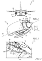
Fig. 1 is a front elevation view of an aircraft including an airframe and a pair of propulsion systems supported by the airframe that each have a gas turbine engine and a nacelle that surrounds a portion of the gas turbine engine and is coupled to the airframe; -
Fig. 2 is a cutaway perspective view of one of the propulsion systems ofFig. 1 detached from the airframe and showing that the nacelle includes a strut that extends downwardly away from the gas turbine engine toward an outer shroud and a pylon that extends upwardly from the gas turbine engine to couple the propulsion system to the airframe; -
Fig. 3 is a detail view of a strut included in the propulsion system ofFig. 2 showing that the nacelle includes a cooling unit housed in the strut and configured to received pressurized bypass air discharged from a fan of the gas turbine engine; -
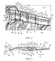
Fig. 4 is a perspective view of the cooling unit ofFig. 3 with portions of the nacelle removed for the sake of simplicity, showing a diverter valve included in the cooling unit in an open position in which pressurized bypass air passing through the cooling unit is directed into contact with a heat exchanger included in the cooling unit; -
Fig. 5 is a simplified plan view of the cooling unit ofFig. 4 showing the pressurized bypass air conducted by a duct included in the cooling unit through the heat exchanger and to an outlet thereof when the diverter valve is in the open position; -
Fig. 6 is a perspective view of the cooling unit similar toFig. 4 showing the diverter valve in a closed position in which pressurized bypass air passing through the cooling unit is diverted around the heat exchanger without contacting the heat exchanger; -
Fig. 7 is a simplified plan view of the cooling unit similar toFig. 5 showing the pressurized bypass air conducted by the duct around the heat exchanger without contacting the heat exchanger and to the outlet thereof when the diverter valve is in the closed position; and -
Fig. 8 is a diagrammatic view of another cooling unit including a duct, a diverter valve positioned in the duct, and a heat exchanger positioned in the duct showing pressurized bypass air conducted by the duct through the heat exchanger to an outlet of the duct when the diverter valve is in a closed position. - Referring now to
Fig. 1 , anillustrative aircraft 10 includes anairframe 12 and a pair ofpropulsion systems airframe 12 opposite one another. Thepropulsions systems aircraft 10 may include any suitable number of propulsion systems other than the twopropulsions systems - Referring now to
Fig. 2 , thepropulsion system 14 illustratively includes anacelle 18 and agas turbine engine 20. Thenacelle 18 is coupled to theairframe 12, as shown inFig. 1 , and surrounds at least a portion of thegas turbine engine 20, as best seen inFig. 2 . Thegas turbine engine 20 is configured to generate thrust to move theaircraft 10 while being supported in thenacelle 18. - The
nacelle 18 illustratively includes apylon 22, astrut 24, and acooling unit 26 as shown inFig. 2 . Thepylon 22 is configured to couple to theairframe 12 and extends away from thegas turbine engine 20. Thestrut 24 also extends away from thegas turbine engine 20 and is spaced from thepylon 22 in a circumferential direction indicated by arrow C. Thecooling unit 26 is housed in thestrut 24 and fluidly coupled to thegas turbine engine 20 to cool fluid from theengine 20 and return the cooled fluid to theengine 20. - In the illustrative embodiment, the
nacelle 18 includes only onestrut 24 and onecooling unit 26 housed in thestrut 24. In other embodiments, however, thenacelle 18 may includemultiple struts 24 that each house onecooling unit 26. - The
gas turbine engine 20 illustratively includes anengine core 28 and afan 30 that is coupled to theengine core 28 to be driven by theengine core 28 as shown inFig. 2 . Theengine core 28 is configured to pass pressurized air therethrough so that the pressurized air flows aftward along anengine axis 32 defined by theengine core 28. Thefan 30 is configured to discharge pressurized bypass air that is passed around theengine core 28 aftward along theengine axis 32. - As best seen in
Figs. 2-3 , the coolingunit 26 illustratively includes aduct 34, aheat exchanger 36, and adiverter valve 38. Theheat exchanger 36 and thediverter valve 38 are positioned within theduct 34, and thediverter valve 38 is movable therein from anopen position 38a (seeFigs. 4-5 ) to aclosed position 38b (seeFigs. 6-7 ). In theopen position 38a, thediverter valve 38 directs the bypass air discharged by thefan 30 through theduct 34 and into contact with theheat exchanger 36. In theclosed position 38b, thediverter valve 38 diverts the bypass air discharged by thefan 30 around theheat exchanger 36 without contacting theheat exchanger 36. The coolingunit 26 is therefore configured to selectively pass bypass air through theheat exchanger 36 during operation of theaircraft 10. - Referring now to
Fig. 3 , when thediverter valve 38 is in theopen position 38a, fluid from theengine core 28 passes along aflow path 28F. Specifically, fluid from theengine core 28 passes along theflow path 28F from one component of theengine core 28 through theheat exchanger 36 and is returned to another component of theengine core 28 by theheat exchanger 36. Fluid is illustratively pressurized air provided to theheat exchanger 36 along theflow path 28F by a compressor of theengine core 28. The pressurized air provided to theheat exchanger 36 is illustratively returned to a turbine of theengine core 28 along theflow path 28F to cool the turbine. - In other embodiments, the
heat exchanger 36 may be adapted to cool oil, fuel, or any other fluid that is provided thereto by theengine core 28 or by any other part of theaircraft 10. In those embodiments, fluid may be provided to theheat exchanger 36 by theengine core 28 or by any other part of theaircraft 10 along another suitable flow path. Additionally, in those embodiments, fluid provided to theheat exchanger 36 may be returned to theengine core 28 or any other part of theaircraft 10 along another suitable flow path. - Referring again to
Fig. 2 , thestrut 24 is illustratively positioned between an engine case 40 of thegas turbine engine 20 that surrounds theengine core 28 and anouter shroud 42 of thenacelle 18. Thestrut 24 is coupled to the engine case 40 to extend outwardly therefrom and away from theengine axis 32 toward theouter shroud 42. As such, the coolingunit 26 is positioned outward of theengine core 28 and inward of theouter shroud 42 in a radial direction indicated by arrow R. - The
strut 24 is illustratively spaced from thepylon 22 about theengine axis 32 in the circumferential direction indicated by arrow C as shown inFig. 2 . Specifically, thestrut 24 is spaced about 180 degrees from thepylon 22 about theaxis 32 in the circumferential direction indicated by arrow C. When thepropulsion system 14 is coupled to theairframe 12 as shown inFig. 1 , thepylon 22 is positioned above thegas turbine engine 20, whereas thestrut 24 is positioned below theengine 20. In other embodiments, however, thestrut 24 and thepylon 22 may be arranged relative to thegas turbine engine 20 in other suitable arrangements. - Referring now to
Fig. 4 , theduct 34 illustratively includesopposite walls strut 24. Each of thewalls engine core 28. Thewalls opposite walls 34c, 34d of theduct 34 that are arranged generally perpendicular to thewalls walls 34c, 34d are generally planar, whereas thewalls walls interior space 44 in which theheat exchanger 36 and thediverter valve 38 are positioned. - The
walls fan 30 and cooperate to define aninlet 46 adjacent thereto that opens toward thefan 30 as shown inFig. 4 . Thewalls heat exchanger 36 to cooperatively define anoutlet 48 that opens toward an exhaust outlet. Theinlet 46 is configured to receive pressurized bypass air discharged by thefan 30 and conduct the bypass air toward theoutlet 48. Theoutlet 48 is configured to discharge bypass air received at theinlet 46 and conducted thereto through theinterior space 44 of theduct 34. - The
duct 34 illustratively includes adivider 50 that is positioned within theinterior space 44 as shown inFig. 4 . Thedivider 50 extends along the length of theduct 34 between theinlet 46 and theoutlet 48 to divide theduct 34 into anouter flow portion 52 and aninner flow portion 54. Theinner flow portion 54 is positioned inward of theouter flow portion 52 in the radial direction indicated by arrow R. - In the illustrative embodiment, the
duct 34 includes only onedivider 50. In other embodiments, however, theduct 34 may include more than onedivider 50. In other embodiments still, theduct 34 may not include adivider 50 at all. - The
outer flow portion 52 is illustratively configured to conduct pressurized bypass air discharged by thefan 30 through theduct 34 as shown inFig. 4 . Specifically, theouter flow portion 52 conducts bypass air discharged by thefan 30 from theinlet 46 to theoutlet 48. Theouter flow portion 52 is defined by thewalls divider 50. - Like the
outer flow portion 52, theinner flow portion 54 is illustratively configured to conduct pressurized bypass air discharged by thefan 30 through theduct 34 as suggested byFig. 4 . Specifically, theinner flow portion 54 conducts bypass air discharged by thefan 30 from theinlet 46 to theoutlet 48. Theinner flow portion 54 is defined by thewalls divider 50. - The
duct 34 illustratively provides two circuits (i.e., outer andinner flow portions 52, 54) for conducting fluid discharged by thefan 30 between theinlet 46 and theoutlet 48 as suggested byFig. 4 . Fluid is conducted by theouter flow portion 52 between theinlet 46 and theoutlet 48 in substantially the same fashion as fluid is conducted by theinner flow portion 54 between theinlet 46 and theoutlet 48. As such, only fluid conducted between theinlet 46 and theoutlet 48 by theouter flow portion 52 is shown inFigs. 4-7 . - The
heat exchanger 36 is illustratively positioned aft of thediverter valve 38 in theinterior space 44 of theduct 34 as shown inFig. 4 . Both theheat exchanger 36 and thediverter valve 38 extend in theinterior space 44 substantially all the way between thewalls 34c, 34d. As such, theheat exchanger 36 and thediverter valve 38 extend through each of the outer andinner flow portions - The
heat exchanger 36 is illustratively configured to transfer heat from the fluid passing along thepath 28F to bypass air discharged from thefan 30 that contacts theheat exchanger 36 as suggested byFig. 4 . Theheat exchanger 36 is illustratively embodied as any device configured for use as described above, subject to size constraints imposed by other components of the coolingunit 26 as described below. In one example, theheat exchanger 36 may be embodied as a tube bank heat exchanger. In another example, theheat exchanger 36 may be embodied as any one of a plate heat exchanger, a plate- and-fin heat exchanger, or the like. - As best seen in
Fig. 5 , theheat exchanger 36 extends in theinterior space 44 of theduct 34 between thewall 34b and aguide post 56 positioned within theinterior space 44. Anaft end 36a of theheat exchanger 36 is received by acurved channel 58 formed in acurved segment 60 of thewall 34b that extends substantially all the way between the walls 36c, 36d. Aforward end 36f of theheat exchanger 36 opposite theaft end 36a is received by acurved surface 62 of theguide post 56 that extends substantially all the way between the walls 36c, 36d. The position of theheat exchanger 36 in theinterior space 44 is maintained by thewall 34b and theguide post 56 as shown inFigs. 4-7 . As such, the size of theheat exchanger 36 is constrained by thewall 34b and theguide post 56. - The
diverter valve 38 illustratively includes aplate 64, anouter actuator 66 coupled to theplate 64, and aninner actuator 68 coupled to theplate 64 opposite theouter actuator 66 as shown inFig. 4 . Theplate 64 is positioned in theinterior space 44 and extends substantially all the way between thewalls 34c, 34d. Theouter actuator 66 is positioned outward in the radial direction indicated by arrow R from the wall 34c. Theinner actuator 68 is positioned inward in the radial direction indicated by arrow R from thewall 34d. - The outer and
inner actuators plate 66 by acylindrical pin 70 that extends through theplate 66 and outside thewalls 34c, 34d as shown inFig. 4 . Thepin 70 is received by abore 72 formed in theplate 66. Thepin 70 defines anaxis 74 that extends in the radial direction indicated by arrow R. - The
plate 64 is slidably engaged with acurved surface 63 of theguide post 56 that is opposite thecurved surface 62 in each of the open andclosed positions diverter valve 38. In theopen position 38a, theplate 64 is engaged with thewall 34a. In contrast, in theclosed position 38b, theplate 64 is engaged with thewall 34b. - The
outer actuator 66 is illustratively operable to pivot theplate 64 about theaxis 74 relative to thewalls open position 38a shown inFigs. 4-5 and theclosed position 38b shown inFigs. 6-7 . In one example, theactuator 66 may be embodied as, or otherwise include, an electrically-powered actuator such as an electrically-powered linear actuator. In another example, theactuator 66 may be embodied as, or otherwise include, a hydraulically-operated actuator such as a hydraulic piston. - The
inner actuator 68 is also illustratively operable to pivot theplate 64 about theaxis 74 relative to thewalls open position 38a shown inFigs. 4-5 and theclosed position 38b shown inFigs. 6-7 . In one example, theactuator 68 may be embodied as, or otherwise include, an electrically-powered actuator such as an electrically-powered linear actuator. In another example, theactuator 68 may be embodied as, or otherwise include, a hydraulically-operated actuator such as a hydraulic piston. - The outer and
inner actuators plate 66 between the open andclosed positions Fig. 4 . To do so, theactuators outer actuator 66 is actuatable to pivot theplate 64 between thepositions inner actuator 68. Conversely, theinner actuator 68 is actuatable to pivot theplate 64 between thepositions outer actuator 66. In that way, theactuators plate 64 between thepositions - The
duct 34 is supported relative to thegas turbine engine 20 and components thereof bysupports 49 as shown inFig. 4 . Two of thesupports 49 are illustratively positioned between theinlet 46 and theheat exchanger 36, and one of thesupports 49 is illustratively positioned between theheat exchanger 36 and theoutlet 48. In other embodiments, however, thesupports 49 may include any suitable number of supports other than three supports that are arranged between theinlet 46 and theoutlet 48 in any other suitable arrangement. - Referring now to
Fig. 5 , fluid flow from anoutlet 31 of thefan 30 to theinlet 46 of theduct 34 is shown in greater detail. Bypass air is discharged byfan blades 33 of thefan 30 at theoutlet 31 to theinlet 46 in adirection 35. Thedirection 35 illustratively has anaxial component 35A in an axial direction indicated by arrow A. Thedirection 35 also has a circumferential component 35C in the circumferential direction indicated by arrow C. Theinlet 46 is shaped to open in the axial direction indicated by arrow A and in the circumferential direction indicated by arrow C. In this way, theinlet 46 is shaped to receive the bypass air discharged by thefan 30 at theoutlet 31 in thedirection 35. Accordingly, substantially all of the total pressure of the bypass air discharged by thefan 30 is captured by theinlet 46 of theduct 34 in operation of thepropulsion system 14. - In other embodiments, the
duct 34 may include another type of inlet adapted for use in the manner described above with regard to theinlet 46. For example, theduct 34 may include a NACA inlet or any other similar inlet that forms a generally smooth contour with a surface of thestrut 24. - The
outer flow portion 52 and theinner flow portion 54 illustratively extend from theinlet 46 to theheat exchanger 36 to definerespective headers Figs. 4-5 . Theheaders fan 30 from theinlet 46 toward theheat exchanger 36. When thediverter valve 38 is in theopen position 38a, bypass air is conducted through theheaders heat exchanger 36. When thediverter valve 38 is in theclosed position 38b, bypass air is conducted through theheaders heat exchanger 36 without contacting theheat exchanger 36. - The
heat exchanger 36 is illustratively positioned within theinterior space 44 of theduct 34 so that theheat exchanger 36 extends along aheat exchanger axis 76A that is substantially perpendicular to aface 76 of acore 77 of theheat exchanger 36 as shown inFig. 5 . Theheat exchanger 36 is arranged to transfer heat from the medium to be cooled (i.e., fluid from theengine core 28 passing along thepath 28F through the face 76) to the cooling medium (i.e., bypass air discharged by the fan 30). - When the
diverter valve 38 is in theopen position 38a, theheader 52H conducts bypass air discharged by thefan 30 from theinlet 46 to theheat exchanger 36 along aforward flow path 78 as shown inFig. 5 . Bypass air is conducted by theheader 52H along thepath 78 through theface 76 at an angle α that is defined between theheat exchanger axis 76A and theengine axis 32. - In the illustrative embodiment, the angle α is somewhere between 30 degrees and 90 degrees. The
header 52H, and also theheader 54H, may be said to be oblique headers. As used herein, oblique headers conduct bypass air toward thecore 77 of theheat exchanger 36 so that the flow of bypass air along theforward flow path 78 is not perpendicular to theface 76 of thecore 77. Theheaders headers heat exchanger axis 76A and theengine axis 32. - When the
diverter valve 38 is in theopen position 38a, bypass air moving along theforward flow path 78 flows through thecore 77 and exits theheat exchanger 36 as shown inFig. 5 . Bypass air exiting theheat exchanger 36 is illustratively conducted by theduct 34 along anaft flow path 80 to theoutlet 48. Beside the portion of theforward flow path 78 passing through theface 76, theforward flow path 78 is generally parallel to theaft flow path 80. - As best seen in
Figs. 5 and7 , theoutlet 48 of theduct 34 is shaped to discharge bypass air in substantially the axial direction indicated by arrow A only to mix with other exhaust of thepropulsion system 14. Bypass air discharged by theoutlet 48 may be communicated to a space positioned outside of thegas turbine engine 20 or thenacelle 20 in some embodiments. - Operation of the
propulsion system 14 will now be described with reference toFigs. 4-5 . During operation of thegas turbine engine 20, the coolingunit 26 is operated so that thediverter valve 38 is in theopen position 38a. When thediverter valve 38 is in theopen position 38a, fluid passes along thepath 28F from theengine core 28 to theheat exchanger 36 and is returned back to theengine core 28 by theheat exchanger 36. Bypass air discharged by thefan 30 flows along theforward flow path 78 and is directed into contact with theheat exchanger 36. The bypass air flows through theheat exchanger 36 such that heat is transferred from the fluid from theengine core 28 to the bypass air. As a result, the temperature of the bypass air increases, and the temperature of the fluid from theengine core 28 decreases. The increased temperature bypass air is then conducted along theaft flow path 80 to theoutlet 48 and discharged therefrom. The cooled fluid from theengine core 28 is returned to theengine core 28 by theheat exchanger 36. The cooled fluid is directed to one or more components of theengine core 28 to manage the temperature of the components(s). - Operation of the
propulsion system 14 will now be described with reference toFigs. 6-7 . During operation of thegas turbine engine 20, the coolingunit 26 is operated so that thediverter valve 38 is in theclosed position 38b. When thediverter valve 38 is in theclosed position 38b, no fluid from theengine core 28 is provided to thecooling unit 26, and bypass air discharged by thefan 30 is diverted around theheat exchanger 36 along aflow path 82. The temperature of the bypass air therefore remains substantially the same as the bypass air flows away from theinlet 46, around theheat exchanger 36, and to theoutlet 48 along thepath 82. - Referring to
Figs. 4-7 , operation of thepropulsion system 14 may vary in certain instances. In one instance, it may be desirable to manage the temperatures of components of theengine core 28. To do so, the coolingunit 26 may be operated to place thediverter valve 38 in theopen position 38a, or in any other position between theopen position 38a and theclosed position 38b to control the cooling of the medium to be cooled (i.e., fluid from the engine core 28). In other instances, it may be desirable to avoid pressure losses resulting from directing fluid from theengine core 28 to thecooling unit 26, and thereby increase the operating efficiency of thegas turbine engine 20. To do so, the coolingunit 26 may be operated to place thediverter valve 38 in theclosed position 38b. In such instances, fluid from theengine core 28 is not cooled by the coolingunit 26. - Referring now to
Fig. 8 , acooling unit 126 is shown in detail. Thecooling unit 126 may be adapted for use in theaircraft 10. Specifically, thecooling unit 126 may be included in thenacelle 18 of thepropulsion system 14 and sized to be positioned in thestrut 24. - The
cooling unit 126 illustratively includes aduct 134, aheat exchanger 136, and adiverter valve 138 as shown inFig. 8 . Theheat exchanger 136 and thediverter valve 138 are positioned within theduct 134, and thediverter valve 138 is movable therein from aclosed position 138c (shown inFig. 8 ) to anopen position 138d (shown in phantom). In theclosed position 138c, thediverter valve 138 directs pressurized bypass air (e.g., bypass air discharged from the fan 30) through theduct 134 and into contact with theheat exchanger 136. In theopen position 138d, thediverter valve 138 permits pressurized bypass air to flow around theheat exchanger 136 without contacting theheat exchanger 136. Thecooling unit 126 is therefore configured to selectively pass bypass air through theheat exchanger 136. - The
duct 134 illustratively includes anouter wall 184 that extends from aninlet 146 of theduct 134 to theheat exchanger 136 to define aheader 152H as shown inFig. 8 . Theheader 152H is configured to conduct pressurized bypass air from theinlet 146 toward theheat exchanger 136. When thediverter valve 138 is in theclosed position 138c, bypass air is conducted through theheader 152H and into contact with theheat exchanger 136. When thediverter valve 138 is in theopen position 138d, at least some of the pressurized bypass air is not conducted through theheader 152H and into contact with theheat exchanger 136. Rather, at least some of the pressurized bypass air is conducted through apassage 186 defined between anouter wall 188 of theduct 134 and aseparator wall 190 of theduct 134 when thediverter valve 138 is in theopen position 138d. In any case, in each of the closed andopen positions passage 186 is conducted to anoutlet 147 of theduct 134 that is arranged opposite theinlet 146. Theouter wall 188 is arranged opposite theouter wall 184 and theseparator wall 190 is arranged between theouter wall 188 and theheat exchanger 136. - When the
diverter valve 138 is in theclosed position 138c, pressurized bypass air is conducted by theheader 152H toward theheat exchanger 136 along aflow path 192 as shown inFig. 8 . Bypass air directed into contact with theheat exchanger 136 by theheader 152H passes through theheat exchanger 136 and around theseparator wall 190 into thepassage 186 along aflow path 194. Portions of theflow paths duct 134 may be said to provide a counterflow arrangement for conducting bypass air from theinlet 146 to theoutlet 147 along theflow paths - The present disclosure may provide means for cooling air discharged by a compressor of a gas turbine engine, such as the
engine 20, using bypass air discharged by a fan, such as the bypass air discharged byfan 30. The present concept may be embodied as an active cooling system that may be packaged as a single unit and placed between the walls of an airframe-mounted lower-bifurcation duct, such as theduct 34. Advantages of the present concept may include minimal impact to the performance of the gas turbine engine, packaging benefits, and size benefits compared to accessories mounted in an engine core, such as theengine core 28, of the engine. - The present concept may provide the ability to meter the bypass air flowing across the heat exchanger, such as the
heat exchanger 36. The heat may be operated in a heat exchanger mode, such as when thediverter valve 38 is in theopen position 38a, and a full bypass mode, such as when thediverter valve 38 is in theclosed position 38b. - The present concept may provide the ability to increase the performance of the gas turbine engine by avoiding a pressure drop when cooling via the heat exchanger is not required. The present concept may also provide the ability to manage the temperature and thermal gradients of engine core components to increase core component life.
- The present concept may have a minimal impact on the engine core of the gas turbine engine. The present concept may be positioned inside an unused lower-bifurcation duct and may extend over a distance that minimizes cold side ducting. The present concept may utilize oblique headers, such as the
headers - The present concept may also provide redundancy through two independent heat exchanger flow circuits, such as the outer and
inner flow portions diverter valve 38, that is actuatable by two actuators in tandem with one another, such as the outer andinner actuators - While the disclosure has been illustrated and described in detail in the foregoing drawings and description, the same is to be considered as exemplary and not restrictive in character, it being understood that only illustrative embodiments thereof have been shown and described and that all changes and modifications that come within the spirit of the disclosure are desired to be protected.
Claims (15)
- A propulsion system (14, 16) for an aircraft (10), the propulsion system (14, 16) comprising
a gas turbine engine (20) including an engine core (28) and a fan (30) coupled to the engine core (28), the fan (30) configured to discharge pressurized bypass air that is passed around the engine core (28), and
a nacelle (18) surrounding a portion of the gas turbine engine (20), the nacelle (18) including a strut (24) that extends away from the gas turbine engine (20) and a cooling unit (26) housed in the strut (24), the cooling unit (26) fluidly coupled to the gas turbine engine (20) to cool fluid or gas from the gas turbine engine (20) and return the cooled fluid or gas to the gas turbine engine (20),
wherein the cooling unit (26) includes a duct (34), a heat exchanger (36) positioned within the duct (34), and a diverter valve (38) that is movable within the duct (34) from a first position (38a) arranged to direct pressurized bypass air moving through the duct (34) into contact with the heat exchanger (36) to a second position (38b) arranged to divert pressurized bypass air around the heat exchanger (36) without contacting the heat exchanger (36). - The propulsion system (14, 16) of claim 1, wherein the cooling unit (26) is positioned radially-outward of the engine core (28) and radially-inward of an outer shroud (42) included in the nacelle (18).
- The propulsion system (14, 16) of claim 1, wherein the duct (34) includes a divider (50) extending along the length of the duct (34) to divide the duct (34) into an outer flow portion (52) and an inner flow portion (54) positioned radially-inward of the outer flow portion (52).
- The propulsion system (14, 16) of claim 1, wherein the diverter valve (38) includes a first actuator (66) and a plate (64) coupled to the first actuator (66), the first actuator (66) operable to pivot the plate (64) relative to the duct (34) between the first and the second positions (38a, 38b).
- The propulsion system (14, 16) of claim 4, wherein the diverter valve (38) includes a second actuator (68) coupled to the plate (64), the second actuator (68) operable to move the plate (64) relative to the duct (34) between the first and the second positions (38a, 38b) in the event of a failure of the first actuator (66).
- The propulsion system (14, 16) of claim 1, wherein (i) the heat exchanger (36) has a core (77) having a face (76), and (ii) pressurized bypass air directed into contact with the heat exchanger (36) by the diverter valve (38) when the diverter valve (38) is in the first position (38a) is conducted by a header (52H, 54H) included in the duct (34) to the core (77) at an angle to the face (76) that is different from 90 degrees.
- The propulsion system (14, 16) of claim 6, wherein pressurized bypass air directed into contact with the heat exchanger (36) by the diverter valve (38) when the diverter valve (38) is in the first position (38a) is conducted by the header (52H, 54H) from an inlet (46) of the duct (34) to the core (77) of the heat exchanger (36) along a forward flow path (78) generally parallel to an aft flow path (80) along which pressurized bypass air is conducted away from the heat exchanger (36) to an outlet (48) of the duct (34).
- The propulsion system (14, 16) of claim 1, wherein (i) the fan (30) is configured to discharge pressurized bypass air in a direction having a circumferential component (35C) and an axial component (35A) at an outlet (48) thereof, and (ii) an inlet (46) of the duct (34) is shaped to open axially and circumferentially to receive the pressurized bypass air discharged from the fan (30) so that the total pressure of the pressurized bypass air is captured by the duct (34) during operation of the propulsion system (14, 16).
- The propulsion system (14, 16) of claim 8, wherein an outlet (48) of the duct (34) is shaped to discharge pressurized bypass air in a substantially axial direction only.
- The propulsion system (14, 16) of claim 1, wherein the diverter valve (38) is movable between the first and second positions (381, 38b) to control cooling of the fluid or gas from the gas turbine engine (20).
- An aircraft (10) comprising
an airframe (12),
a gas turbine engine (20) supported by the airframe (12), the gas turbine engine (20) including an engine core (28) defining an engine axis (32) and a fan (30) coupled to the engine core (28), the fan (30) configured to discharge pressurized bypass air that is passed around the engine core (28), and
a nacelle (18) supported by the airframe (12) and surrounding a portion of the gas turbine engine (20), the nacelle (18) including a pylon (22) coupled to the airframe (12), a strut (24) that is spaced from the pylon (22) and extends outwardly from the gas turbine engine (20) away from the engine axis (32), and a cooling unit (26) housed in the strut (24) that is fluidly coupled to the gas turbine engine (20) to cool fluid or gas from the gas turbine engine (20),
wherein the cooling unit (26) is configured to receive pressurized bypass air from the fan (30) and to pass the pressurized bypass air through a heat exchanger (36) included in the cooling unit (26) during operation of the aircraft (10). - The aircraft (10) of claim 11, wherein the pylon (22) is spaced about 180 degrees from the strut (24) and the cooling unit (26) about the engine axis (32).
- The aircraft (10) of claim 11, wherein the cooling unit (26) includes a duct (34) having walls (34a, 34b) housed in the strut (24) and a diverter valve (38) that is movable within the duct (34) from a first position (38a) arranged to direct pressurized bypass air moving through the duct (34) into contact with the heat exchanger (36) to a second position (38b) arranged to divert pressurized bypass air around the heat exchanger (36) without contacting the heat exchanger (36).
- The aircraft (10) of claim 13, wherein the duct (34) includes a divider (50) extending along the length of the duct (34) to divide the duct (34) into an outer flow portion (52) and an inner flow portion (54) positioned radially-inward of the outer flow portion (52).
- The aircraft (10) of claim 13, wherein the diverter valve (38) includes a first actuator (66) and a plate (64) coupled to the first actuator (66), the first actuator (66) operable to pivot the plate (64) relative to the duct (34) between the first and the second positions (38a, 38b),
wherein the diverter valve (38) includes a second actuator (68) coupled to the plate (64), the second actuator (68) operable to move the plate (64) relative to the duct (34) between the first and the second positions (38a, 38b) in the event of a failure of the first actuator (66),
wherein (i) the heat exchanger (36) has a core (77) having a face (76), and (ii) pressurized bypass air directed into contact with the heat exchanger (36) by the diverter valve (38) when the diverter valve (38) is in the first position (38a) is conducted by a header (52H, 54H) included in the duct (34) to the core (77) at an angle to the face (76) that is different from 90 degrees,
wherein pressurized bypass air directed into contact with the heat exchanger (36) by the diverter valve (38) when the diverter valve (38) is in the first position (38a) is conducted by the header (52H, 54H) from an inlet (46) of the duct (34) to the core (77) of the heat exchanger (36) along a forward flow path (78) generally parallel to an aft flow path (80) along which pressurized bypass air is conducted away from the heat exchanger (36) to an outlet (48) of the duct (34),
wherein (i) the fan (30) is configured to discharge pressurized bypass air in a direction having a circumferential component (35C) and an axial component (35A) at an outlet (48) thereof, and (ii) an inlet (46) of the duct (34) is shaped to open axially and circumferentially to receive pressurized bypass air discharged from the fan (30) so that the total pressure of the pressurized bypass air is captured by the duct (34) during operation of the aircraft (10),
wherein an outlet (48) of the duct (34) is shaped to discharge pressurized bypass air in a substantially axial direction only, and
wherein the cooling unit (26) is positioned radially-outward of the engine core (28) and radially-inward of an outer shroud (42) included in the nacelle (18).
Applications Claiming Priority (1)
| Application Number | Priority Date | Filing Date | Title |
|---|---|---|---|
| US201562204260P | 2015-08-12 | 2015-08-12 |
Publications (2)
| Publication Number | Publication Date |
|---|---|
| EP3130539A1 true EP3130539A1 (en) | 2017-02-15 |
| EP3130539B1 EP3130539B1 (en) | 2020-04-08 |
Family
ID=56842590
Family Applications (1)
| Application Number | Title | Priority Date | Filing Date |
|---|---|---|---|
| EP16180259.0A Active EP3130539B1 (en) | 2015-08-12 | 2016-07-20 | Heat exchanger for a gas turbine engine propulsion system |
Country Status (3)
| Country | Link |
|---|---|
| US (1) | US10677166B2 (en) |
| EP (1) | EP3130539B1 (en) |
| CA (1) | CA2936633C (en) |
Cited By (11)
| Publication number | Priority date | Publication date | Assignee | Title |
|---|---|---|---|---|
| US11927134B1 (en) | 2023-01-27 | 2024-03-12 | General Electric Company | Gas turbine engine having a heat exchanger located in an annular duct |
| US11965697B2 (en) | 2021-03-02 | 2024-04-23 | General Electric Company | Multi-fluid heat exchanger |
| US12123350B2 (en) | 2021-03-02 | 2024-10-22 | General Electric Company | Three-stream engine having a heat exchanger |
| US12188433B2 (en) | 2022-12-16 | 2025-01-07 | Rolls-Royce Plc | Thermal management system for a gas turbine engine |
| US12313022B1 (en) | 2023-01-27 | 2025-05-27 | General Electric Company | Gas turbine engine having a heat exchanger located in an annular duct |
| US12378932B2 (en) | 2023-01-27 | 2025-08-05 | General Electric Company | Gas turbine engine having a heat exchanger located in an annular duct |
| US12421896B2 (en) | 2023-01-27 | 2025-09-23 | General Electric Company | Gas turbine engine having a heat exchanger located in an annular duct |
| US12448936B2 (en) | 2023-01-27 | 2025-10-21 | General Electric Company | Gas turbine engine having a heat exchanger located in an annular duct |
| US12560118B2 (en) | 2023-01-27 | 2026-02-24 | General Electric Company | Gas turbine engine having a heat exchanger located in an annular duct |
| US12601296B2 (en) | 2023-01-27 | 2026-04-14 | General Electric Company | Gas turbine engine having a heat exchanger located in an annular duct |
| US12601297B2 (en) | 2023-01-27 | 2026-04-14 | General Electric Company | Gas turbine engine having a heat exchanger located in an annular duct |
Families Citing this family (38)
| Publication number | Priority date | Publication date | Assignee | Title |
|---|---|---|---|---|
| EP3130539B1 (en) | 2015-08-12 | 2020-04-08 | Rolls-Royce North American Technologies, Inc. | Heat exchanger for a gas turbine engine propulsion system |
| US10513981B2 (en) * | 2016-01-21 | 2019-12-24 | Rolls-Royce North American Technologies Inc. | Heat exchanger assembly for a gas turbine engine propulsion system |
| US20180162537A1 (en) | 2016-12-09 | 2018-06-14 | United Technologies Corporation | Environmental control system air circuit |
| US11725584B2 (en) | 2018-01-17 | 2023-08-15 | General Electric Company | Heat engine with heat exchanger |
| RU2680636C1 (en) * | 2018-05-14 | 2019-02-25 | Федеральное государственное унитарное предприятие "Центральный институт авиационного моторостроения имени П.И. Баранова" | Cooling system of a multi-circuit gas turbine unit |
| US11174816B2 (en) | 2019-02-25 | 2021-11-16 | Rolls-Royce Corporation | Bypass duct conformal heat exchanger array |
| US10927761B2 (en) | 2019-04-17 | 2021-02-23 | General Electric Company | Refreshing heat management fluid in a turbomachine |
| US11378009B2 (en) | 2019-05-15 | 2022-07-05 | Raytheon Technologies Corporation | Multi-mode heat rejection system for a gas turbine engine |
| US11492971B2 (en) * | 2019-09-06 | 2022-11-08 | Raytheon Technologies Corporation | Turbine engine system with heat exchanger in bypassable secondary duct |
| FR3108682B1 (en) * | 2020-03-30 | 2022-12-09 | Safran Aircraft Engines | Retractable air-oil heat exchanger for aircraft propulsion system |
| FR3117528B1 (en) * | 2020-12-11 | 2023-03-31 | Safran Aircraft Engines | HEAT EXCHANGER MOUNTED IN A CAVITY OF A TURBOMACHINE |
| US11396376B1 (en) | 2021-01-04 | 2022-07-26 | Cameron Carnegie | Y-shaped airliner and associated methods |
| US20220213802A1 (en) | 2021-01-06 | 2022-07-07 | General Electric Company | System for controlling blade clearances within a gas turbine engine |
| US11897624B2 (en) | 2021-02-01 | 2024-02-13 | General Electric Company | Method for thermal management for an aircraft propulsion system using a flow of compressed fluid extracted from a compressor section |
| US11434824B2 (en) | 2021-02-03 | 2022-09-06 | General Electric Company | Fuel heater and energy conversion system |
| US12286927B2 (en) | 2021-02-08 | 2025-04-29 | General Electric Company | Vehicle with energy conversion system |
| US11788470B2 (en) | 2021-03-01 | 2023-10-17 | General Electric Company | Gas turbine engine thermal management |
| US11591965B2 (en) | 2021-03-29 | 2023-02-28 | General Electric Company | Thermal management system for transferring heat between fluids |
| US11674396B2 (en) | 2021-07-30 | 2023-06-13 | General Electric Company | Cooling air delivery assembly |
| US11920500B2 (en) | 2021-08-30 | 2024-03-05 | General Electric Company | Passive flow modulation device |
| US12410752B2 (en) | 2021-09-23 | 2025-09-09 | General Electric Company | System and method of detecting an airflow fault condition |
| US11702958B2 (en) | 2021-09-23 | 2023-07-18 | General Electric Company | System and method of regulating thermal transport bus pressure |
| US11692448B1 (en) | 2022-03-04 | 2023-07-04 | General Electric Company | Passive valve assembly for a nozzle of a gas turbine engine |
| GB2617377A (en) * | 2022-04-07 | 2023-10-11 | Rolls Royce Plc | Gas turbine engine |
| US12535033B2 (en) | 2022-11-01 | 2026-01-27 | General Electric Company | Gas turbine engine |
| US12618378B2 (en) | 2022-11-01 | 2026-05-05 | General Electric Company | Gas turbine engine |
| US12503980B2 (en) | 2022-11-01 | 2025-12-23 | General Electric Company | Gas turbine engine |
| US12410753B2 (en) | 2022-11-01 | 2025-09-09 | General Electric Company | Gas turbine engine |
| US12392290B2 (en) | 2022-11-01 | 2025-08-19 | General Electric Company | Gas turbine engine |
| US12618332B2 (en) | 2022-11-01 | 2026-05-05 | General Electric Company | Gas turbine engine |
| US12428992B2 (en) | 2022-11-01 | 2025-09-30 | General Electric Company | Gas turbine engine |
| US12196131B2 (en) | 2022-11-01 | 2025-01-14 | General Electric Company | Gas turbine engine |
| US12510025B2 (en) * | 2023-02-17 | 2025-12-30 | General Electric Company | Reverse flow gas turbine engine having electric machine |
| US12553382B2 (en) | 2023-07-31 | 2026-02-17 | Rolls-Royce North American Technologies Inc. | Integrated bypass duct heat exchanger |
| US12163488B1 (en) * | 2023-09-07 | 2024-12-10 | Rtx Corporation | Selectable inlet for aircraft propulsion system heat exchanger |
| US12291997B1 (en) | 2024-04-30 | 2025-05-06 | General Electric Company | Variable area turbine nozzle assembly |
| US20250369394A1 (en) * | 2024-05-31 | 2025-12-04 | Rtx Corporation | Scoop fed heat exchange for an open rotor gas turbine engine |
| US12540551B1 (en) | 2025-07-01 | 2026-02-03 | General Electric Company | Gas turbine engines including splittered airfoils |
Citations (5)
| Publication number | Priority date | Publication date | Assignee | Title |
|---|---|---|---|---|
| US20070245738A1 (en) * | 2006-04-20 | 2007-10-25 | Stretton Richard G | Heat exchanger arrangement |
| EP1876328A2 (en) * | 2006-07-06 | 2008-01-09 | United Technologies Corporation | Heat exchange system in a turbofan engine |
| EP2085599A2 (en) * | 2008-01-25 | 2009-08-05 | United Technologies Corporation | Shared flow thermal management system |
| US20130164115A1 (en) * | 2011-12-21 | 2013-06-27 | General Electric Company | Bleed air and hot section component cooling air system and method |
| EP3106646A1 (en) * | 2015-06-16 | 2016-12-21 | United Technologies Corporation | Cooled cooling air system for a turbofan engine |
Family Cites Families (31)
| Publication number | Priority date | Publication date | Assignee | Title |
|---|---|---|---|---|
| US4254618A (en) | 1977-08-18 | 1981-03-10 | General Electric Company | Cooling air cooler for a gas turbofan engine |
| US4187675A (en) | 1977-10-14 | 1980-02-12 | The United States Of America As Represented By The Secretary Of The Air Force | Compact air-to-air heat exchanger for jet engine application |
| FR2656657A1 (en) | 1989-12-28 | 1991-07-05 | Snecma | AIR COOLED TURBOMACHINE AND METHOD FOR COOLING THE SAME. |
| US5123242A (en) * | 1990-07-30 | 1992-06-23 | General Electric Company | Precooling heat exchange arrangement integral with mounting structure fairing of gas turbine engine |
| US5269135A (en) | 1991-10-28 | 1993-12-14 | General Electric Company | Gas turbine engine fan cooled heat exchanger |
| US6106229A (en) | 1997-12-22 | 2000-08-22 | United Technologies Corporation | Heat exchanger system for a gas turbine engine |
| US6672072B1 (en) | 1998-08-17 | 2004-01-06 | General Electric Company | Pressure boosted compressor cooling system |
| GB9911871D0 (en) | 1999-05-22 | 1999-07-21 | Rolls Royce Plc | A gas turbine engine and a method of controlling a gas turbine engine |
| US6550253B2 (en) | 2001-09-12 | 2003-04-22 | General Electric Company | Apparatus and methods for controlling flow in turbomachinery |
| FR2889254B1 (en) | 2005-07-28 | 2011-05-06 | Airbus France | AIRCRAFT TURBOREACTOR, PROPELLER ASSEMBLY COMPRISING SUCH A TURBOJET ENGINE, AND AIRCRAFT HAVING AT LEAST ONE SUCH A PROPELLER ASSEMBLY |
| GB2437969B (en) | 2006-04-13 | 2011-03-23 | Rolls Royce Plc | Flow control systems |
| US8387362B2 (en) | 2006-10-19 | 2013-03-05 | Michael Ralph Storage | Method and apparatus for operating gas turbine engine heat exchangers |
| US7823389B2 (en) | 2006-11-15 | 2010-11-02 | General Electric Company | Compound clearance control engine |
| US9212623B2 (en) | 2007-12-26 | 2015-12-15 | United Technologies Corporation | Heat exchanger arrangement for turbine engine |
| JP4929217B2 (en) | 2008-03-28 | 2012-05-09 | 三菱重工業株式会社 | Gas turbine, gas turbine intermediate shaft, and gas turbine compressor cooling method |
| US8266889B2 (en) | 2008-08-25 | 2012-09-18 | General Electric Company | Gas turbine engine fan bleed heat exchanger system |
| GB0818047D0 (en) | 2008-10-03 | 2008-11-05 | Rolls Royce Plc | Turbine cooling system |
| US8181443B2 (en) | 2008-12-10 | 2012-05-22 | Pratt & Whitney Canada Corp. | Heat exchanger to cool turbine air cooling flow |
| US8307662B2 (en) | 2009-10-15 | 2012-11-13 | General Electric Company | Gas turbine engine temperature modulated cooling flow |
| US8397487B2 (en) | 2011-02-28 | 2013-03-19 | General Electric Company | Environmental control system supply precooler bypass |
| US8583294B2 (en) * | 2011-04-11 | 2013-11-12 | Hamilton Sundstrand Corporation | Actuation control system |
| US8794009B2 (en) | 2012-01-31 | 2014-08-05 | United Technologies Corporation | Gas turbine engine buffer system |
| US9435259B2 (en) | 2012-02-27 | 2016-09-06 | United Technologies Corporation | Gas turbine engine cooling system |
| WO2014051678A1 (en) | 2012-09-28 | 2014-04-03 | United Technologies Corporation | Gas turbine engine thermal management system for heat exchanger using bypass flow |
| US10385777B2 (en) | 2012-10-01 | 2019-08-20 | United Technologies Corporation | Bifurcated inlet scoop for gas turbine engine |
| EP2951419B1 (en) | 2013-01-29 | 2018-09-05 | United Technologies Corporation | Gas turbine engine with lower bifurcation heat exchanger |
| US9249730B2 (en) | 2013-01-31 | 2016-02-02 | General Electric Company | Integrated inducer heat exchanger for gas turbines |
| US20140250895A1 (en) | 2013-03-11 | 2014-09-11 | United Technologies Corporation | Modulated ejector cooling |
| CN106460677B (en) | 2014-05-21 | 2018-09-18 | 西门子能源公司 | Method of providing cooling flow from a compressor to a turbine in a gas turbine |
| EP3130539B1 (en) | 2015-08-12 | 2020-04-08 | Rolls-Royce North American Technologies, Inc. | Heat exchanger for a gas turbine engine propulsion system |
| US10253785B2 (en) | 2016-08-31 | 2019-04-09 | Unison Industries, Llc | Engine heat exchanger and method of forming |
-
2016
- 2016-07-20 EP EP16180259.0A patent/EP3130539B1/en active Active
- 2016-07-20 CA CA2936633A patent/CA2936633C/en active Active
- 2016-08-03 US US15/227,543 patent/US10677166B2/en active Active
Patent Citations (5)
| Publication number | Priority date | Publication date | Assignee | Title |
|---|---|---|---|---|
| US20070245738A1 (en) * | 2006-04-20 | 2007-10-25 | Stretton Richard G | Heat exchanger arrangement |
| EP1876328A2 (en) * | 2006-07-06 | 2008-01-09 | United Technologies Corporation | Heat exchange system in a turbofan engine |
| EP2085599A2 (en) * | 2008-01-25 | 2009-08-05 | United Technologies Corporation | Shared flow thermal management system |
| US20130164115A1 (en) * | 2011-12-21 | 2013-06-27 | General Electric Company | Bleed air and hot section component cooling air system and method |
| EP3106646A1 (en) * | 2015-06-16 | 2016-12-21 | United Technologies Corporation | Cooled cooling air system for a turbofan engine |
Cited By (12)
| Publication number | Priority date | Publication date | Assignee | Title |
|---|---|---|---|---|
| US11965697B2 (en) | 2021-03-02 | 2024-04-23 | General Electric Company | Multi-fluid heat exchanger |
| US12123350B2 (en) | 2021-03-02 | 2024-10-22 | General Electric Company | Three-stream engine having a heat exchanger |
| US12281850B2 (en) | 2021-03-02 | 2025-04-22 | General Electric Company | Multi-fluid heat exchanger |
| US12188433B2 (en) | 2022-12-16 | 2025-01-07 | Rolls-Royce Plc | Thermal management system for a gas turbine engine |
| US11927134B1 (en) | 2023-01-27 | 2024-03-12 | General Electric Company | Gas turbine engine having a heat exchanger located in an annular duct |
| US12313022B1 (en) | 2023-01-27 | 2025-05-27 | General Electric Company | Gas turbine engine having a heat exchanger located in an annular duct |
| US12378932B2 (en) | 2023-01-27 | 2025-08-05 | General Electric Company | Gas turbine engine having a heat exchanger located in an annular duct |
| US12421896B2 (en) | 2023-01-27 | 2025-09-23 | General Electric Company | Gas turbine engine having a heat exchanger located in an annular duct |
| US12448936B2 (en) | 2023-01-27 | 2025-10-21 | General Electric Company | Gas turbine engine having a heat exchanger located in an annular duct |
| US12560118B2 (en) | 2023-01-27 | 2026-02-24 | General Electric Company | Gas turbine engine having a heat exchanger located in an annular duct |
| US12601296B2 (en) | 2023-01-27 | 2026-04-14 | General Electric Company | Gas turbine engine having a heat exchanger located in an annular duct |
| US12601297B2 (en) | 2023-01-27 | 2026-04-14 | General Electric Company | Gas turbine engine having a heat exchanger located in an annular duct |
Also Published As
| Publication number | Publication date |
|---|---|
| US10677166B2 (en) | 2020-06-09 |
| CA2936633C (en) | 2021-12-28 |
| CA2936633A1 (en) | 2017-02-12 |
| EP3130539B1 (en) | 2020-04-08 |
| US20170044984A1 (en) | 2017-02-16 |
Similar Documents
| Publication | Publication Date | Title |
|---|---|---|
| EP3130539B1 (en) | Heat exchanger for a gas turbine engine propulsion system | |
| EP3196454B1 (en) | Heat exchanger assembly for a gas turbine engine propulsion system | |
| ES2715843T3 (en) | Heat exchange systems and methods to control air flow cooling | |
| EP2644847B1 (en) | Turbine engine heat recuperator system | |
| CA2936632C (en) | Integral oil tank heat exchanger | |
| JP6259219B2 (en) | Heat exchanger assembly and gas turbine engine assembly | |
| US10082079B2 (en) | Gas-turbine engine with oil cooler in the engine cowling | |
| US20150000291A1 (en) | Gas turbine engine combustor heat exchanger | |
| US20150285147A1 (en) | Cooling System with a Bearing Compartment Bypass | |
| US20160069266A1 (en) | Heat exchanger arrangement for turbine engine | |
| EP3117169B1 (en) | Heat exchanger | |
| US20140341717A1 (en) | Shroud arrangement for a gas turbine engine | |
| US20260001655A1 (en) | Exhaust cone heat exchanger (hex) | |
| JPH08505682A (en) | Gas turbine engine exhaust gas type anti-icing system | |
| JP5493122B2 (en) | Fluid resistance reduction device | |
| JP2017025910A (en) | Cooling structure for fixed blades | |
| JP6928004B2 (en) | Radial flow turbine heat engine | |
| US20230194185A1 (en) | Evolutive precooler | |
| GB2525971A (en) | Heat Exchanger | |
| EP3508710B1 (en) | Systems for cooling a coolant airflow | |
| KR101852357B1 (en) | leading edge cooling apparatus of gas turbine nozzle and cooling method | |
| CN115485196B (en) | A hovering aircraft | |
| US20250320824A1 (en) | Turbomachine for a flight propulsion drive | |
| CN114810356A (en) | Heat exchange system |
Legal Events
| Date | Code | Title | Description |
|---|---|---|---|
| PUAI | Public reference made under article 153(3) epc to a published international application that has entered the european phase |
Free format text: ORIGINAL CODE: 0009012 |
|
| STAA | Information on the status of an ep patent application or granted ep patent |
Free format text: STATUS: THE APPLICATION HAS BEEN PUBLISHED |
|
| AK | Designated contracting states |
Kind code of ref document: A1 Designated state(s): AL AT BE BG CH CY CZ DE DK EE ES FI FR GB GR HR HU IE IS IT LI LT LU LV MC MK MT NL NO PL PT RO RS SE SI SK SM TR |
|
| AX | Request for extension of the european patent |
Extension state: BA ME |
|
| STAA | Information on the status of an ep patent application or granted ep patent |
Free format text: STATUS: REQUEST FOR EXAMINATION WAS MADE |
|
| 17P | Request for examination filed |
Effective date: 20170807 |
|
| RBV | Designated contracting states (corrected) |
Designated state(s): AL AT BE BG CH CY CZ DE DK EE ES FI FR GB GR HR HU IE IS IT LI LT LU LV MC MK MT NL NO PL PT RO RS SE SI SK SM TR |
|
| STAA | Information on the status of an ep patent application or granted ep patent |
Free format text: STATUS: EXAMINATION IS IN PROGRESS |
|
| 17Q | First examination report despatched |
Effective date: 20180615 |
|
| GRAP | Despatch of communication of intention to grant a patent |
Free format text: ORIGINAL CODE: EPIDOSNIGR1 |
|
| STAA | Information on the status of an ep patent application or granted ep patent |
Free format text: STATUS: GRANT OF PATENT IS INTENDED |
|
| INTG | Intention to grant announced |
Effective date: 20191212 |
|
| GRAS | Grant fee paid |
Free format text: ORIGINAL CODE: EPIDOSNIGR3 |
|
| GRAA | (expected) grant |
Free format text: ORIGINAL CODE: 0009210 |
|
| STAA | Information on the status of an ep patent application or granted ep patent |
Free format text: STATUS: THE PATENT HAS BEEN GRANTED |
|
| AK | Designated contracting states |
Kind code of ref document: B1 Designated state(s): AL AT BE BG CH CY CZ DE DK EE ES FI FR GB GR HR HU IE IS IT LI LT LU LV MC MK MT NL NO PL PT RO RS SE SI SK SM TR |
|
| REG | Reference to a national code |
Ref country code: CH Ref legal event code: EP Ref country code: AT Ref legal event code: REF Ref document number: 1254065 Country of ref document: AT Kind code of ref document: T Effective date: 20200415 |
|
| REG | Reference to a national code |
Ref country code: DE Ref legal event code: R096 Ref document number: 602016033410 Country of ref document: DE |
|
| REG | Reference to a national code |
Ref country code: IE Ref legal event code: FG4D |
|
| REG | Reference to a national code |
Ref country code: NL Ref legal event code: MP Effective date: 20200408 |
|
| REG | Reference to a national code |
Ref country code: LT Ref legal event code: MG4D |
|
| PG25 | Lapsed in a contracting state [announced via postgrant information from national office to epo] |
Ref country code: IS Free format text: LAPSE BECAUSE OF FAILURE TO SUBMIT A TRANSLATION OF THE DESCRIPTION OR TO PAY THE FEE WITHIN THE PRESCRIBED TIME-LIMIT Effective date: 20200808 Ref country code: PT Free format text: LAPSE BECAUSE OF FAILURE TO SUBMIT A TRANSLATION OF THE DESCRIPTION OR TO PAY THE FEE WITHIN THE PRESCRIBED TIME-LIMIT Effective date: 20200817 Ref country code: LT Free format text: LAPSE BECAUSE OF FAILURE TO SUBMIT A TRANSLATION OF THE DESCRIPTION OR TO PAY THE FEE WITHIN THE PRESCRIBED TIME-LIMIT Effective date: 20200408 Ref country code: NL Free format text: LAPSE BECAUSE OF FAILURE TO SUBMIT A TRANSLATION OF THE DESCRIPTION OR TO PAY THE FEE WITHIN THE PRESCRIBED TIME-LIMIT Effective date: 20200408 Ref country code: NO Free format text: LAPSE BECAUSE OF FAILURE TO SUBMIT A TRANSLATION OF THE DESCRIPTION OR TO PAY THE FEE WITHIN THE PRESCRIBED TIME-LIMIT Effective date: 20200708 Ref country code: FI Free format text: LAPSE BECAUSE OF FAILURE TO SUBMIT A TRANSLATION OF THE DESCRIPTION OR TO PAY THE FEE WITHIN THE PRESCRIBED TIME-LIMIT Effective date: 20200408 Ref country code: GR Free format text: LAPSE BECAUSE OF FAILURE TO SUBMIT A TRANSLATION OF THE DESCRIPTION OR TO PAY THE FEE WITHIN THE PRESCRIBED TIME-LIMIT Effective date: 20200709 Ref country code: SE Free format text: LAPSE BECAUSE OF FAILURE TO SUBMIT A TRANSLATION OF THE DESCRIPTION OR TO PAY THE FEE WITHIN THE PRESCRIBED TIME-LIMIT Effective date: 20200408 |
|
| REG | Reference to a national code |
Ref country code: AT Ref legal event code: MK05 Ref document number: 1254065 Country of ref document: AT Kind code of ref document: T Effective date: 20200408 |
|
| PG25 | Lapsed in a contracting state [announced via postgrant information from national office to epo] |
Ref country code: BG Free format text: LAPSE BECAUSE OF FAILURE TO SUBMIT A TRANSLATION OF THE DESCRIPTION OR TO PAY THE FEE WITHIN THE PRESCRIBED TIME-LIMIT Effective date: 20200708 Ref country code: LV Free format text: LAPSE BECAUSE OF FAILURE TO SUBMIT A TRANSLATION OF THE DESCRIPTION OR TO PAY THE FEE WITHIN THE PRESCRIBED TIME-LIMIT Effective date: 20200408 Ref country code: HR Free format text: LAPSE BECAUSE OF FAILURE TO SUBMIT A TRANSLATION OF THE DESCRIPTION OR TO PAY THE FEE WITHIN THE PRESCRIBED TIME-LIMIT Effective date: 20200408 Ref country code: RS Free format text: LAPSE BECAUSE OF FAILURE TO SUBMIT A TRANSLATION OF THE DESCRIPTION OR TO PAY THE FEE WITHIN THE PRESCRIBED TIME-LIMIT Effective date: 20200408 |
|
| PG25 | Lapsed in a contracting state [announced via postgrant information from national office to epo] |
Ref country code: AL Free format text: LAPSE BECAUSE OF FAILURE TO SUBMIT A TRANSLATION OF THE DESCRIPTION OR TO PAY THE FEE WITHIN THE PRESCRIBED TIME-LIMIT Effective date: 20200408 |
|
| REG | Reference to a national code |
Ref country code: DE Ref legal event code: R097 Ref document number: 602016033410 Country of ref document: DE |
|
| PG25 | Lapsed in a contracting state [announced via postgrant information from national office to epo] |
Ref country code: DK Free format text: LAPSE BECAUSE OF FAILURE TO SUBMIT A TRANSLATION OF THE DESCRIPTION OR TO PAY THE FEE WITHIN THE PRESCRIBED TIME-LIMIT Effective date: 20200408 Ref country code: EE Free format text: LAPSE BECAUSE OF FAILURE TO SUBMIT A TRANSLATION OF THE DESCRIPTION OR TO PAY THE FEE WITHIN THE PRESCRIBED TIME-LIMIT Effective date: 20200408 Ref country code: SM Free format text: LAPSE BECAUSE OF FAILURE TO SUBMIT A TRANSLATION OF THE DESCRIPTION OR TO PAY THE FEE WITHIN THE PRESCRIBED TIME-LIMIT Effective date: 20200408 Ref country code: AT Free format text: LAPSE BECAUSE OF FAILURE TO SUBMIT A TRANSLATION OF THE DESCRIPTION OR TO PAY THE FEE WITHIN THE PRESCRIBED TIME-LIMIT Effective date: 20200408 Ref country code: ES Free format text: LAPSE BECAUSE OF FAILURE TO SUBMIT A TRANSLATION OF THE DESCRIPTION OR TO PAY THE FEE WITHIN THE PRESCRIBED TIME-LIMIT Effective date: 20200408 Ref country code: CZ Free format text: LAPSE BECAUSE OF FAILURE TO SUBMIT A TRANSLATION OF THE DESCRIPTION OR TO PAY THE FEE WITHIN THE PRESCRIBED TIME-LIMIT Effective date: 20200408 Ref country code: IT Free format text: LAPSE BECAUSE OF FAILURE TO SUBMIT A TRANSLATION OF THE DESCRIPTION OR TO PAY THE FEE WITHIN THE PRESCRIBED TIME-LIMIT Effective date: 20200408 Ref country code: RO Free format text: LAPSE BECAUSE OF FAILURE TO SUBMIT A TRANSLATION OF THE DESCRIPTION OR TO PAY THE FEE WITHIN THE PRESCRIBED TIME-LIMIT Effective date: 20200408 |
|
| PLBE | No opposition filed within time limit |
Free format text: ORIGINAL CODE: 0009261 |
|
| STAA | Information on the status of an ep patent application or granted ep patent |
Free format text: STATUS: NO OPPOSITION FILED WITHIN TIME LIMIT |
|
| PG25 | Lapsed in a contracting state [announced via postgrant information from national office to epo] |
Ref country code: MC Free format text: LAPSE BECAUSE OF FAILURE TO SUBMIT A TRANSLATION OF THE DESCRIPTION OR TO PAY THE FEE WITHIN THE PRESCRIBED TIME-LIMIT Effective date: 20200408 Ref country code: SK Free format text: LAPSE BECAUSE OF FAILURE TO SUBMIT A TRANSLATION OF THE DESCRIPTION OR TO PAY THE FEE WITHIN THE PRESCRIBED TIME-LIMIT Effective date: 20200408 Ref country code: PL Free format text: LAPSE BECAUSE OF FAILURE TO SUBMIT A TRANSLATION OF THE DESCRIPTION OR TO PAY THE FEE WITHIN THE PRESCRIBED TIME-LIMIT Effective date: 20200408 |
|
| REG | Reference to a national code |
Ref country code: CH Ref legal event code: PL |
|
| 26N | No opposition filed |
Effective date: 20210112 |
|
| GBPC | Gb: european patent ceased through non-payment of renewal fee |
Effective date: 20200720 |
|
| REG | Reference to a national code |
Ref country code: BE Ref legal event code: MM Effective date: 20200731 |
|
| PG25 | Lapsed in a contracting state [announced via postgrant information from national office to epo] |
Ref country code: FR Free format text: LAPSE BECAUSE OF NON-PAYMENT OF DUE FEES Effective date: 20200731 Ref country code: GB Free format text: LAPSE BECAUSE OF NON-PAYMENT OF DUE FEES Effective date: 20200720 Ref country code: CH Free format text: LAPSE BECAUSE OF NON-PAYMENT OF DUE FEES Effective date: 20200731 Ref country code: LU Free format text: LAPSE BECAUSE OF NON-PAYMENT OF DUE FEES Effective date: 20200720 Ref country code: LI Free format text: LAPSE BECAUSE OF NON-PAYMENT OF DUE FEES Effective date: 20200731 |
|
| PG25 | Lapsed in a contracting state [announced via postgrant information from national office to epo] |
Ref country code: BE Free format text: LAPSE BECAUSE OF NON-PAYMENT OF DUE FEES Effective date: 20200731 Ref country code: SI Free format text: LAPSE BECAUSE OF FAILURE TO SUBMIT A TRANSLATION OF THE DESCRIPTION OR TO PAY THE FEE WITHIN THE PRESCRIBED TIME-LIMIT Effective date: 20200408 |
|
| PG25 | Lapsed in a contracting state [announced via postgrant information from national office to epo] |
Ref country code: IE Free format text: LAPSE BECAUSE OF NON-PAYMENT OF DUE FEES Effective date: 20200720 |
|
| PG25 | Lapsed in a contracting state [announced via postgrant information from national office to epo] |
Ref country code: TR Free format text: LAPSE BECAUSE OF FAILURE TO SUBMIT A TRANSLATION OF THE DESCRIPTION OR TO PAY THE FEE WITHIN THE PRESCRIBED TIME-LIMIT Effective date: 20200408 Ref country code: MT Free format text: LAPSE BECAUSE OF FAILURE TO SUBMIT A TRANSLATION OF THE DESCRIPTION OR TO PAY THE FEE WITHIN THE PRESCRIBED TIME-LIMIT Effective date: 20200408 Ref country code: CY Free format text: LAPSE BECAUSE OF FAILURE TO SUBMIT A TRANSLATION OF THE DESCRIPTION OR TO PAY THE FEE WITHIN THE PRESCRIBED TIME-LIMIT Effective date: 20200408 |
|
| PG25 | Lapsed in a contracting state [announced via postgrant information from national office to epo] |
Ref country code: MK Free format text: LAPSE BECAUSE OF FAILURE TO SUBMIT A TRANSLATION OF THE DESCRIPTION OR TO PAY THE FEE WITHIN THE PRESCRIBED TIME-LIMIT Effective date: 20200408 |
|
| P01 | Opt-out of the competence of the unified patent court (upc) registered |
Effective date: 20230528 |
|
| PGFP | Annual fee paid to national office [announced via postgrant information from national office to epo] |
Ref country code: DE Payment date: 20250728 Year of fee payment: 10 |