EP3130534A1 - Airplane wing assembly - Google Patents
Airplane wing assembly Download PDFInfo
- Publication number
- EP3130534A1 EP3130534A1 EP15846306.7A EP15846306A EP3130534A1 EP 3130534 A1 EP3130534 A1 EP 3130534A1 EP 15846306 A EP15846306 A EP 15846306A EP 3130534 A1 EP3130534 A1 EP 3130534A1
- Authority
- EP
- European Patent Office
- Prior art keywords
- bushing
- joint
- hole
- shearing
- winglet
- Prior art date
- Legal status (The legal status is an assumption and is not a legal conclusion. Google has not performed a legal analysis and makes no representation as to the accuracy of the status listed.)
- Granted
Links
Images


Classifications
-
- B—PERFORMING OPERATIONS; TRANSPORTING
- B64—AIRCRAFT; AVIATION; COSMONAUTICS
- B64C—AEROPLANES; HELICOPTERS
- B64C23/00—Influencing air flow over aircraft surfaces, not otherwise provided for
- B64C23/06—Influencing air flow over aircraft surfaces, not otherwise provided for by generating vortices
- B64C23/065—Influencing air flow over aircraft surfaces, not otherwise provided for by generating vortices at the wing tips
- B64C23/069—Influencing air flow over aircraft surfaces, not otherwise provided for by generating vortices at the wing tips using one or more wing tip airfoil devices, e.g. winglets, splines, wing tip fences or raked wingtips
-
- B—PERFORMING OPERATIONS; TRANSPORTING
- B64—AIRCRAFT; AVIATION; COSMONAUTICS
- B64C—AEROPLANES; HELICOPTERS
- B64C3/00—Wings
- B64C3/18—Spars; Ribs; Stringers
- B64C3/187—Ribs
-
- B—PERFORMING OPERATIONS; TRANSPORTING
- B64—AIRCRAFT; AVIATION; COSMONAUTICS
- B64C—AEROPLANES; HELICOPTERS
- B64C3/00—Wings
- B64C3/38—Adjustment of complete wings or parts thereof
- B64C3/52—Warping
-
- B—PERFORMING OPERATIONS; TRANSPORTING
- B64—AIRCRAFT; AVIATION; COSMONAUTICS
- B64F—GROUND OR AIRCRAFT-CARRIER-DECK INSTALLATIONS SPECIALLY ADAPTED FOR USE IN CONNECTION WITH AIRCRAFT; DESIGNING, MANUFACTURING, ASSEMBLING, CLEANING, MAINTAINING OR REPAIRING AIRCRAFT, NOT OTHERWISE PROVIDED FOR; HANDLING, TRANSPORTING, TESTING OR INSPECTING AIRCRAFT COMPONENTS, NOT OTHERWISE PROVIDED FOR
- B64F5/00—Designing, manufacturing, assembling, cleaning, maintaining or repairing aircraft, not otherwise provided for; Handling, transporting, testing or inspecting aircraft components, not otherwise provided for
-
- Y—GENERAL TAGGING OF NEW TECHNOLOGICAL DEVELOPMENTS; GENERAL TAGGING OF CROSS-SECTIONAL TECHNOLOGIES SPANNING OVER SEVERAL SECTIONS OF THE IPC; TECHNICAL SUBJECTS COVERED BY FORMER USPC CROSS-REFERENCE ART COLLECTIONS [XRACs] AND DIGESTS
- Y02—TECHNOLOGIES OR APPLICATIONS FOR MITIGATION OR ADAPTATION AGAINST CLIMATE CHANGE
- Y02T—CLIMATE CHANGE MITIGATION TECHNOLOGIES RELATED TO TRANSPORTATION
- Y02T50/00—Aeronautics or air transport
- Y02T50/10—Drag reduction
Definitions
- the present disclosure relates to an aircraft wing assembly, and more specifically relates to an aircraft wing assembly that can implement an interchangeable connection between a winglet and a wing box.
- a winglet is an aerodynamic efficiency sensitive component located at a wing tip and deigned for reducing an induced drag for an aircraft, reducing tip vortex, lowering fuel consumption, and enhancing competitiveness of the aircraft. Its installation posture should be strictly guaranteed. Meanwhile, the winglet component is located in a lightning strike I-A zone such that it is susceptible to lightning strike or easily damaged due to crash with a boarding bridge, another plane or a building in adjacency when the aircraft is parking and taxing. The winglet has a relatively small structure, and thus when the winglet is damaged seriously, it is usually directly replaced in consideration of maintenance, cost, and aerodynamic efficiency factors. Furthermore, because the winglet is of a closed structure, it needs to be installed/removed for multiple times for structural maintenance and overhaul during its service.
- a connection between a winglet and a wing may provide a good interchangeability with the winglet installation posture well guaranteed so as to enhance its maintenance.
- connection structure that provides a natural positioning datum for installing a winglet and a wing box such that with the positioning datum, the installation posture of a winglet is guaranteed and meanwhile an interchangeability requirement of the winglet is guaranteed.
- an aircraft wing assembly including: an aircraft wing having a wing box; a winglet disposed at a wing tip of the aircraft wing and connected to the aircraft wing through the wing box; a connection part comprising a joint rib for being assembled with the wing box and a central joint for being assembled with the winglet, wherein the joint rib has a first shearing pin hole and a second shearing pin hole for being pressed with corresponding first and second shearing pins to form an interference fit, respectively; the central joint has a first bushing hole and a second bushing hole for being pressed with corresponding first and second bushings to form an interference fit; a positional relationship between the first shearing pin hole and the second shearing pin hole is identical to that between the first bushing hole and the second bushing hole, such that when the winglet assembled with the central joint moves towards the wing box assembled with the joint rib, and when the first and second shearing pins are inserted
- connection part further includes a first round bushing and a second round bushing for being pressed into the first and second shearing pins' holes, and the first and second shearing pins are pressed into the first and second round bushings, such that a secure interference fit is achieved between the first and second shearing pins and the first and second round bushings, respectively.
- the second bushing hole is larger than the first bushing hole
- the connection part further includes a third bushing larger than the second bushing for being pressed into the second bushing hole, such that the second bushing hole is pressed into the third bushing to form an interference fit.
- an inner hole of the second bushing is of an elongated round shape.
- bottoms of the first and second shearing pins' holes are provided with a round hole, respectively, for exhausting gas when the shearing pins are pressed in and/or for ejecting out the shearing pins through the round holes for change.
- the center joint is further equipped with a plurality of barrel nuts
- the connection part further includes a plurality of tension bolts for being inserted through the joint rib after clearance fits are achieved between the first and second shearing pins and the first and second bushings, and being threaded tightly in the plurality of barrel nuts till the joint rib is adhered to a joint plane of the center joint.
- the tension bolts form clearance fits with via-holes on the joint rib and with via-holes on the center joint, respectively.
- a number of the barrel nuts and that of the tension bolts are both 6.
- such relative positional relationships between two shearing pins and the two bushing holes provide a natural positioning datum when assembling a winglet.
- the posture of the winglet is uniquely determined.
- a rear one of the two bushing holes is designed into an elongated round shape, which provides assembling compensation in consideration of fabrication tolerance.
- the fits between the shearing pins and the central joint of the winglet are clearance fit with tight tolerance, which guarantees a smooth installation/removal and ensures a good load transferring while guaranteeing interchangeability of the winglet.
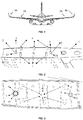
- Fig. 1 illustrates a schematic diagram of a positional relationship between an aircraft wing and a winglet in the prior art.
- the winglet 10 is located at a wing tip position of an aircraft wing 20 and is connected to the wing 20 through a specific connection part.
- the wing 20 has a wing box (not shown) and the winglet 10 is connected to the wing 20 through the wing box.
- the connection part between the winglet 10 and the wing 20 includes a joint rib and a central joint.
- the joint rib is assembled with the wing box of the wing 20, and the center joint is assembled with the winglet.
- the central joint is assembled at a root of the winglet, while the joint rib is assembled at a tip of the wing box.
- a face that attaches the center joint of the winglet to the joint rib of the wing box is a reference plane.
- Fig. 2 illustrates a structural schematic diagram of the joint rib.
- Fig. 3 illustrates a schematic diagram of a center joint of the winglet.
- the joint rib 1 has two shearing pins' holes 31 for being pressed with corresponding shearing pins 3, respectively.
- the fit between the shearing pins 3 and the shearing pins' holes 31 is an interference fit, which guarantees a good load transferring.
- the shearing pin has a function of a locating pin and is designed to enable an interference fit between the shearing pin and the wing box and a clearance fit between the shearing pin and the center joint of the winglet.
- two round bushings 2 are pressed into the two shearing pins' holes 31 to form an interference fit, and then the shearing pins are pressed into the two round bushings 2, such that the bushings 2 and the shearing pins 3 form a secure interference fit.
- the fit between the shearing pins 3 and the shearing pins' holes 31 and the fit between the shearing pins 3 and the round bushings 2 are both interference fits so as to guarantee a good load transferring during assembling.
- Fig. 4 illustrates a schematic diagram of connections of shearing pins according to the present disclosure.
- a round hole 11 is provided at a bottom of the hearing pin hole 31, for exhausting gas when the shearing pin 3 is pressed in, or for ejecting out the shearing pin 3 through the round holes 11 by using a tool when changing the shearing pin 3 during the service procedure.
- the center joint 9 of the winglet 10 has a front side bushing hole 51 and a rear side bushing hole 61, in which bushings 5 and 6 are pressed therein, respectively.
- the fits between the bushings 5 and 6 and corresponding bushing holes 51 and 61 are also interference fits, which guarantees a good load transferring during assembling.
- two shearing pins' holes 31 and two bushing holes 51 and 61 are located on a central axis of the joint rib 1 and that of the center joint 9.
- the rear side bushing hole 61 is larger than the front side bushing hole 51.
- a bushing 7 larger than the bushing 6 may be first pressed in the rear side bushing hole 61, and then the bushing 6 is pressed in the inner of the bushing 7. More preferably, the fit between the bushing hole 61 and the bushing 7 and that between the bushing 6 and the bushing 7 are also interference fits, so as to guarantee good load transferring during assembling.
- the inner hole of the bushing 6 is of an elongated round shape so as to provide assembly compensation under a certain fabrication tolerance.
- the elongated round shape refers to a shape formed by a rectangle in the middle while two semi-circles at respective sides, which is also referred to as a runway shape.
- a positional relationship between the two shearing pins' holes 31 is identical to that between the two bushing holes 51 and 61, such that during assembling of the winglet 10, when the winglet 10 assembled with the central joint 9 moves towards the wing box assembled with the joint rib 1, and when the two shearing pins 3 are inserted into the two bushing holes 51 and 61 on the center joint 9, respectively, a small clearance fit is achieved between the shearing pins 3 and the two bushings 5 and 6, respectively.
- Such a clearance fit between the shearing pins and the center joint of the winglet may guarantee smooth installation/removal of the winglet, while the interference fit between the shearing pin and the shearing pin's hole or the round bushing at the joint rib side and the interference fit between the bushing and the bushing hole at the center junction side of the winglet can further guarantee interchangeability of components of the winglet while ensuring a good load transferring.
- the center joint 9 is also pre-installed with a plurality of barrel nuts 8.
- the center joint 9 is naturally adhered to a plane of the joint rib 1; then a plurality of tension bolts 4 are inserted into the respective barrel nuts 8 pre-installed in the central joint 9 through the joint rib 1, and the barrel nuts 8 are securely screwed till the joint rib 1 is adhered to the joint plane of the center joint 9.
- a clearance fit is formed between the tension bolt 4 and the via-hole 12 on the joint rib 1 and between the tension bolt 4 and the via-hole 13 on the center joint 9, respectively.
- joint between the winglet 10 and the wing 20 is achieved.
- Fig. 5 illustrates a schematic diagram of the connection relationship between the tension bolts 4 and the barrel nuts 8.
- Fig. 6 illustrates a schematic diagram of the joint rib and the center joint of the winglet after the bolts are installed.
- Fig. 7 illustrates a schematic diagram of installation passages between the tension bolts 4 and the barrel nuts 8. As illustrated in Fig. 7 , the tension bolts 4 are inserted into the barrel nuts 8 through the maintenance ports at an inner side of the joint rib 1 on a lower wing surface.
- the design above provides a natural positioning datum when assembling the winglet, such that when the two shearing pins are mated with the adhering reference face in place, the posture of the winglet is uniquely determined.
Landscapes
- Engineering & Computer Science (AREA)
- Aviation & Aerospace Engineering (AREA)
- Mechanical Engineering (AREA)
- Manufacturing & Machinery (AREA)
- Transportation (AREA)
- Connection Of Plates (AREA)
Abstract
Description
- The present disclosure relates to an aircraft wing assembly, and more specifically relates to an aircraft wing assembly that can implement an interchangeable connection between a winglet and a wing box.
- A winglet is an aerodynamic efficiency sensitive component located at a wing tip and deigned for reducing an induced drag for an aircraft, reducing tip vortex, lowering fuel consumption, and enhancing competitiveness of the aircraft. Its installation posture should be strictly guaranteed. Meanwhile, the winglet component is located in a lightning strike I-A zone such that it is susceptible to lightning strike or easily damaged due to crash with a boarding bridge, another plane or a building in adjacency when the aircraft is parking and taxing. The winglet has a relatively small structure, and thus when the winglet is damaged seriously, it is usually directly replaced in consideration of maintenance, cost, and aerodynamic efficiency factors. Furthermore, because the winglet is of a closed structure, it needs to be installed/removed for multiple times for structural maintenance and overhaul during its service.
- Therefore, it is desirable that a connection between a winglet and a wing may provide a good interchangeability with the winglet installation posture well guaranteed so as to enhance its maintenance.
- A known solution for implementing an interchangeable connection between a winglet and a wing is disclosed for example in a US patent application filed by Airbus Operations Limited with a publication No.
US 20140117158 (A1 ). However, the connection manner employed in that application uses 14 hinging lugs that need to satisfy a requirement of proper alignment with high precision, and thus the processing techniques of parts are highly complex and it is difficult to align during assembling of the winglet. - In view of the above problems, the present disclosure provides a connection structure that provides a natural positioning datum for installing a winglet and a wing box such that with the positioning datum, the installation posture of a winglet is guaranteed and meanwhile an interchangeability requirement of the winglet is guaranteed.
- According to an embodiment of the present disclosure, there is provided an aircraft wing assembly, including: an aircraft wing having a wing box; a winglet disposed at a wing tip of the aircraft wing and connected to the aircraft wing through the wing box; a connection part comprising a joint rib for being assembled with the wing box and a central joint for being assembled with the winglet, wherein the joint rib has a first shearing pin hole and a second shearing pin hole for being pressed with corresponding first and second shearing pins to form an interference fit, respectively; the central joint has a first bushing hole and a second bushing hole for being pressed with corresponding first and second bushings to form an interference fit; a positional relationship between the first shearing pin hole and the second shearing pin hole is identical to that between the first bushing hole and the second bushing hole, such that when the winglet assembled with the central joint moves towards the wing box assembled with the joint rib, and when the first and second shearing pins are inserted into the first bushing hole and the second bushing hole on the center joint, respectively, a small clearance fit is achieved between the first and second shearing pins and the first and second bushings, respectively.
- Preferably, the connection part further includes a first round bushing and a second round bushing for being pressed into the first and second shearing pins' holes, and the first and second shearing pins are pressed into the first and second round bushings, such that a secure interference fit is achieved between the first and second shearing pins and the first and second round bushings, respectively.
- Preferably, the second bushing hole is larger than the first bushing hole, and the connection part further includes a third bushing larger than the second bushing for being pressed into the second bushing hole, such that the second bushing hole is pressed into the third bushing to form an interference fit.
- Preferably, an inner hole of the second bushing is of an elongated round shape.
- Preferably, bottoms of the first and second shearing pins' holes are provided with a round hole, respectively, for exhausting gas when the shearing pins are pressed in and/or for ejecting out the shearing pins through the round holes for change.
- Preferably, the center joint is further equipped with a plurality of barrel nuts, and the connection part further includes a plurality of tension bolts for being inserted through the joint rib after clearance fits are achieved between the first and second shearing pins and the first and second bushings, and being threaded tightly in the plurality of barrel nuts till the joint rib is adhered to a joint plane of the center joint.
- Preferably, the tension bolts form clearance fits with via-holes on the joint rib and with via-holes on the center joint, respectively.
- Preferably, a number of the barrel nuts and that of the tension bolts are both 6.
- With the solution of the present disclosure, such relative positional relationships between two shearing pins and the two bushing holes provide a natural positioning datum when assembling a winglet. When the two shearing pins and the adhering reference planes readily mate, the posture of the winglet is uniquely determined. Further, a rear one of the two bushing holes is designed into an elongated round shape, which provides assembling compensation in consideration of fabrication tolerance. The fits between the shearing pins and the central joint of the winglet are clearance fit with tight tolerance, which guarantees a smooth installation/removal and ensures a good load transferring while guaranteeing interchangeability of the winglet.
- After reading the description of the preferred embodiments of the present disclosure with reference to the accompanying drawings, the present disclosure will be better understood, and other objectives, details, features and advantages of the present disclosure will become more apparent. In the accompanying drawings:
- Fig. 1
- illustrates a schematic diagram of a positional relationship between an aircraft wing and a winglet in the prior art;
- Fig. 2
- illustrates a structural schematic diagram of a joint rib;
- Fig. 3
- illustrates a schematic diagram of a center joint of a winglet;
- Fig. 4
- illustrates a schematic diagram of connections of shearing pins according to the present disclosure;
- Fig. 5
- illustrates a schematic diagram of the connection relationship between tension bolts and barrel nuts;
- Fig. 6
- illustrates a schematic diagram of the joint rib and the center joint of the winglet after the bolts are installed; and
- Fig. 7
- illustrates a schematic diagram of installation passages between the tension bolts and the barrel nuts.
- Hereinafter, the preferred embodiments of the present disclosure will be described in more detail with reference to the accompanying drawings. Although the preferred embodiments of the present disclosure are illustrated in the drawings, it should be understood that the present disclosure may be implemented in various forms and should not be limited by the embodiments illustrated here. On the contrary, providing of these embodiments is to make the present disclosure more thorough and complete so as to be capable of conveying the scope of the present disclosure completely to those skilled in the art.
-
Fig. 1 illustrates a schematic diagram of a positional relationship between an aircraft wing and a winglet in the prior art. As illustrated inFig. 1 , thewinglet 10 is located at a wing tip position of anaircraft wing 20 and is connected to thewing 20 through a specific connection part. Thewing 20 has a wing box (not shown) and thewinglet 10 is connected to thewing 20 through the wing box. - According to the embodiments of the present disclosure, the connection part between the
winglet 10 and thewing 20 includes a joint rib and a central joint. The joint rib is assembled with the wing box of thewing 20, and the center joint is assembled with the winglet. Preferably, the central joint is assembled at a root of the winglet, while the joint rib is assembled at a tip of the wing box. Preferably, a face that attaches the center joint of the winglet to the joint rib of the wing box is a reference plane.Fig. 2 illustrates a structural schematic diagram of the joint rib.Fig. 3 illustrates a schematic diagram of a center joint of the winglet. - As illustrated in
Fig. 2 , thejoint rib 1 has two shearing pins'holes 31 for being pressed withcorresponding shearing pins 3, respectively. Preferably, the fit between theshearing pins 3 and the shearing pins'holes 31 is an interference fit, which guarantees a good load transferring. - Herein, the shearing pin has a function of a locating pin and is designed to enable an interference fit between the shearing pin and the wing box and a clearance fit between the shearing pin and the center joint of the winglet.
- Preferably, when the shearing
pin 3 is installed, tworound bushings 2 are pressed into the two shearing pins'holes 31 to form an interference fit, and then the shearing pins are pressed into the tworound bushings 2, such that thebushings 2 and theshearing pins 3 form a secure interference fit. In other words, the fit between the shearingpins 3 and the shearing pins'holes 31 and the fit between the shearingpins 3 and theround bushings 2 are both interference fits so as to guarantee a good load transferring during assembling. -
Fig. 4 illustrates a schematic diagram of connections of shearing pins according to the present disclosure. As illustrated inFig. 4 , in a preferred implementation, around hole 11 is provided at a bottom of thehearing pin hole 31, for exhausting gas when the shearingpin 3 is pressed in, or for ejecting out the shearingpin 3 through theround holes 11 by using a tool when changing the shearingpin 3 during the service procedure. - As illustrated in
Fig. 2 , thecenter joint 9 of thewinglet 10 has a frontside bushing hole 51 and a rearside bushing hole 61, in whichbushings bushings corresponding bushing holes - Preferably, two shearing pins'
holes 31 and twobushing holes joint rib 1 and that of thecenter joint 9. - Preferably, the rear
side bushing hole 61 is larger than the frontside bushing hole 51. A bushing 7 larger than thebushing 6 may be first pressed in the rearside bushing hole 61, and then thebushing 6 is pressed in the inner of the bushing 7. More preferably, the fit between thebushing hole 61 and the bushing 7 and that between thebushing 6 and the bushing 7 are also interference fits, so as to guarantee good load transferring during assembling. - More preferably, the inner hole of the
bushing 6 is of an elongated round shape so as to provide assembly compensation under a certain fabrication tolerance. Here, the elongated round shape refers to a shape formed by a rectangle in the middle while two semi-circles at respective sides, which is also referred to as a runway shape. - A positional relationship between the two shearing pins'
holes 31 is identical to that between the twobushing holes winglet 10, when thewinglet 10 assembled with the central joint 9 moves towards the wing box assembled with thejoint rib 1, and when the twoshearing pins 3 are inserted into the twobushing holes bushings - Such a clearance fit between the shearing pins and the center joint of the winglet may guarantee smooth installation/removal of the winglet, while the interference fit between the shearing pin and the shearing pin's hole or the round bushing at the joint rib side and the interference fit between the bushing and the bushing hole at the center junction side of the winglet can further guarantee interchangeability of components of the winglet while ensuring a good load transferring.
- The center joint 9 is also pre-installed with a plurality of barrel nuts 8. When the clearance fits are implemented between the shearing pins 3 and the
bushings joint rib 1; then a plurality oftension bolts 4 are inserted into therespective barrel nuts 8 pre-installed in the central joint 9 through thejoint rib 1, and thebarrel nuts 8 are securely screwed till thejoint rib 1 is adhered to the joint plane of thecenter joint 9. Preferably, a clearance fit is formed between thetension bolt 4 and the via-hole 12 on thejoint rib 1 and between thetension bolt 4 and the via-hole 13 on the center joint 9, respectively. - After a desired torque is applied, joint between the
winglet 10 and thewing 20 is achieved. -
Fig. 5 illustrates a schematic diagram of the connection relationship between thetension bolts 4 and the barrel nuts 8.Fig. 6 illustrates a schematic diagram of the joint rib and the center joint of the winglet after the bolts are installed. -
Fig. 7 illustrates a schematic diagram of installation passages between thetension bolts 4 and the barrel nuts 8. As illustrated inFig. 7 , thetension bolts 4 are inserted into thebarrel nuts 8 through the maintenance ports at an inner side of thejoint rib 1 on a lower wing surface. - The design above provides a natural positioning datum when assembling the winglet, such that when the two shearing pins are mated with the adhering reference face in place, the posture of the winglet is uniquely determined.
- The above depiction of the present disclosure is for enabling any person of normal skill in the art to implement or use the present disclosure. For a person of normal skill in the art, various modifications of the present disclosure are obvious, and a generality principle defined herein may also be applied to other modifications without departing from the spirit and protection scope of the present disclosure. Therefore, the present disclosure is not limited to the instances and designs disclosed herein; instead, it is consistent with the principle and the broadest scope of novelty features of the present disclosure.
Claims (8)
- An aircraft wing assembly, comprising:an aircraft wing (20) having a wing box;a winglet (10) disposed at a wing tip of the aircraft wing (20) and connected to the aircraft wing (20) through the wing box;a connection part comprising a joint rib (1) for being assembled with the wing box and a central joint (9) for being assembled with the winglet,wherein the joint rib (1) has first and second shearing pins' holes (31) for being pressed with corresponding first and second shearing pins (3) to form an interference fit, respectively; the central joint (9) has a first and second bushing holes (51, 61) for being pressed with corresponding first and second bushings (5, 6) to form an interference fit; a positional relationship between the first shearing pin's hole (31) and the second shearing pin's hole (31) is identical to that between the first bushing hole (51) and the second bushing hole (61), such that when the winglet (10) assembled with the central joint (9) moves towards the wing box assembled with the joint rib (1), and when the first and second shearing pins (3) are inserted into the first bushing hole (51) and the second bushing hole (61) on the center joint (9), respectively, a small clearance fit is achieved between the first and second shearing pins (3) and the first bushing (5) and the second bushing (6), respectively.
- The aircraft wing assembly according to claim 1, wherein the connection part further comprises a first round bushing (2) and a second round bushing (2) for being pressed into the first and second shearing pins' holes (31), and the first and second shearing pins (3) are pressed into the first and second round bushings (2), such that a secure interference fit is achieved between the first and second shearing pins (3) and the first and second round bushings (2), respectively.
- The aircraft wing assembly according to claim 1, wherein the second bushing hole (61) is larger than the first bushing hole (51), and the connection part further comprises a third bushing (7) larger than the second bushing (6) for being pressed into the second bushing hole (61), such that the second bushing hole (6) is pressed into the third bushing (7) to form an interference fit.
- The aircraft wing assembly according to claim 3, wherein an inner hole of the second bushing (6) is of an elongated round shape.
- The aircraft wing assembly according to claim 1, wherein bottoms of the first and second shearing pins' holes (31) are provided with a round hole, respectively, for exhausting gas when the shearing pins (3) are pressed in and/or for ejecting out the shearing pins (3) through the round holes (11) for change.
- The aircraft wing assembly according to claim 1, wherein the center joint is further equipped with a plurality of barrel nuts (8), and the connection part further comprises a plurality of tension bolts (4) for being inserted through the joint rib (1) after clearance fits are achieved between the first and second shearing pins (3) and the first bushing (5) and the second bushing (6), and being threaded tightly in the plurality of barrel nuts (8) till the joint rib (1) is adhered to a joint plane of the center joint (9).
- The aircraft wing assembly according to claim 6, wherein the tension bolts (4) form clearance fits with via-holes (12) on the joint rib (1) and with via-holes (13) on the center joint (9), respectively.
- The aircraft wing assembly according to claim 6, wherein a number of the barrel nuts (8) and that of the tension bolts (6) are both 6.
Applications Claiming Priority (2)
| Application Number | Priority Date | Filing Date | Title |
|---|---|---|---|
| CN201410520467.9A CN104290900B (en) | 2014-09-30 | aircraft wing assembly | |
| PCT/CN2015/091041 WO2016050198A1 (en) | 2014-09-30 | 2015-09-29 | Airplane wing assembly |
Publications (3)
| Publication Number | Publication Date |
|---|---|
| EP3130534A1 true EP3130534A1 (en) | 2017-02-15 |
| EP3130534A4 EP3130534A4 (en) | 2018-01-24 |
| EP3130534B1 EP3130534B1 (en) | 2020-03-18 |
Family
ID=52310905
Family Applications (1)
| Application Number | Title | Priority Date | Filing Date |
|---|---|---|---|
| EP15846306.7A Active EP3130534B1 (en) | 2014-09-30 | 2015-09-29 | Airplane wing assembly |
Country Status (3)
| Country | Link |
|---|---|
| US (1) | US10272990B2 (en) |
| EP (1) | EP3130534B1 (en) |
| WO (1) | WO2016050198A1 (en) |
Cited By (2)
| Publication number | Priority date | Publication date | Assignee | Title |
|---|---|---|---|---|
| EP3473539A1 (en) * | 2017-10-19 | 2019-04-24 | Airbus Operations Limited | An aircraft assembly including a wingtip device |
| EP3718877A1 (en) * | 2019-03-28 | 2020-10-07 | Airbus Operations Limited | A joint for an aircraft assembly |
Families Citing this family (4)
| Publication number | Priority date | Publication date | Assignee | Title |
|---|---|---|---|---|
| CN107745798B (en) * | 2017-10-23 | 2023-08-25 | 中国商用飞机有限责任公司北京民用飞机技术研究中心 | An aircraft notch central span-wise beam and wing root connection structure |
| CN109018392A (en) * | 2018-09-27 | 2018-12-18 | 西安爱生技术集团公司 | It is a kind of for protecting the banjo fixing butt jointing of unmanned plane wing |
| US12473073B2 (en) * | 2023-12-20 | 2025-11-18 | The Boeing Company | Wingtip attachment with a reduction in in-tank work and aerodynamic drag |
| CN120207579B (en) * | 2025-05-30 | 2025-09-09 | 中国直升机设计研究所 | A central wing box and an electric tilting helicopter composite wing |
Family Cites Families (28)
| Publication number | Priority date | Publication date | Assignee | Title |
|---|---|---|---|---|
| US2468425A (en) * | 1945-07-20 | 1949-04-26 | Carpenter Joseph David | Airplane wing folding mechanism |
| US2609165A (en) * | 1948-01-20 | 1952-09-02 | Northrop Aircraft Inc | Flap positioning control system |
| US4776542A (en) * | 1987-05-27 | 1988-10-11 | Vigyan Research Associates, Inc. | Aircraft stall-spin entry deterrent system |
| US5201479A (en) * | 1992-01-30 | 1993-04-13 | The Boeing Company | Self-monitoring latch pin lock for folding wing aircraft |
| US5350135A (en) * | 1992-01-30 | 1994-09-27 | The Boeing Company | Latch pin inhibitor for folding wing-tip aircraft |
| US5381986A (en) * | 1992-01-30 | 1995-01-17 | The Boeing Company | Folding wing-tip system |
| CA2291275C (en) * | 1997-06-13 | 2007-11-06 | The Boeing Company | Blunt-leading-edge raked wingtips |
| GB0326228D0 (en) * | 2003-11-10 | 2003-12-17 | Airbus Uk Ltd | Wing tip device |
| US7237750B2 (en) | 2004-10-29 | 2007-07-03 | L3 Communications | Autonomous, back-packable computer-controlled breakaway unmanned aerial vehicle (UAV) |
| US8544800B2 (en) * | 2005-07-21 | 2013-10-01 | The Boeing Company | Integrated wingtip extensions for jet transport aircraft and other types of aircraft |
| CN101288067B (en) | 2005-08-09 | 2012-04-04 | 沙力股份有限公司 | Methods and apparatuses to assemble, extract and deploy content from electronic documents |
| DE102006055090A1 (en) | 2006-11-21 | 2008-05-29 | Airbus Deutschland Gmbh | Wing i.e. airfoil wing, end form for wing of commercial aircraft, has transition area arranged between wing and winglet, where local V-form changes continuously from wing to winglet in transition area |
| US7737898B2 (en) | 2007-03-01 | 2010-06-15 | L-3 Communications Integrated Systems, L.P. | Very high frequency line of sight winglet antenna |
| US8083185B2 (en) * | 2007-11-07 | 2011-12-27 | The Boeing Company | Aircraft wing tip having a variable incidence angle |
| CN100509556C (en) | 2007-12-28 | 2009-07-08 | 北京航空航天大学 | Connecting structure for middle and outside wings of unmanned aerial vehicle |
| US8128020B2 (en) | 2008-04-22 | 2012-03-06 | The Boeing Company | Active twisting of an aircraft lifting surface via modulated clamping of substructure |
| US7975965B2 (en) | 2008-05-13 | 2011-07-12 | The Boeing Company | Wing tip joint in airfoils |
| CN201999199U (en) | 2011-03-15 | 2011-10-05 | 成都飞机设计研究所 | Novel light wingtip winglet structure for unmanned aerial vehicles |
| PL66584Y1 (en) | 2011-03-23 | 2013-06-28 | Ladzinska Sylwia Metal Master | Aircraft wing |
| GB201105104D0 (en) | 2011-03-28 | 2011-05-11 | Airbus Operations Ltd | Joint |
| JP2012245832A (en) * | 2011-05-26 | 2012-12-13 | Kawada Kogyo Kk | Wing structure of small size drone airplane |
| GB201110493D0 (en) | 2011-06-21 | 2011-08-03 | Airbus Operations Ltd | Aircraft wing with wing tip device |
| US9499252B2 (en) * | 2011-10-01 | 2016-11-22 | The Boeing Company | Wing fold controller |
| US9211946B2 (en) * | 2011-10-01 | 2015-12-15 | The Boeing Company | Wing fold system with latch pins through multiple mating lugs |
| US9914523B2 (en) * | 2012-10-30 | 2018-03-13 | The Boeing Company | Wing hinge assembly including hinged torque boxes |
| US9415857B2 (en) * | 2012-10-30 | 2016-08-16 | The Boeing Company | Wing fold system |
| US9145203B2 (en) | 2012-10-31 | 2015-09-29 | The Boeing Company | Natural laminar flow wingtip |
| US9452825B2 (en) | 2013-04-19 | 2016-09-27 | The Boeing Company | Winglet attach fitting for attaching a split winglet to a wing |
-
2015
- 2015-09-29 WO PCT/CN2015/091041 patent/WO2016050198A1/en not_active Ceased
- 2015-09-29 US US15/309,933 patent/US10272990B2/en active Active
- 2015-09-29 EP EP15846306.7A patent/EP3130534B1/en active Active
Cited By (5)
| Publication number | Priority date | Publication date | Assignee | Title |
|---|---|---|---|---|
| EP3473539A1 (en) * | 2017-10-19 | 2019-04-24 | Airbus Operations Limited | An aircraft assembly including a wingtip device |
| US11260964B2 (en) | 2017-10-19 | 2022-03-01 | Airbus Operations Limited | Aircraft assembly including a wing tip device |
| US11905001B2 (en) | 2017-10-19 | 2024-02-20 | Airbus Operations Limited | Wingtip to wing aircraft connection assembly |
| EP3718877A1 (en) * | 2019-03-28 | 2020-10-07 | Airbus Operations Limited | A joint for an aircraft assembly |
| US11703071B2 (en) | 2019-03-28 | 2023-07-18 | Airbus Operations Limited | Joint for an aircraft assembly |
Also Published As
| Publication number | Publication date |
|---|---|
| WO2016050198A1 (en) | 2016-04-07 |
| EP3130534B1 (en) | 2020-03-18 |
| CN104290900A (en) | 2015-01-21 |
| EP3130534A4 (en) | 2018-01-24 |
| US10272990B2 (en) | 2019-04-30 |
| US20170267333A1 (en) | 2017-09-21 |
Similar Documents
| Publication | Publication Date | Title |
|---|---|---|
| US10272990B2 (en) | Aircraft wing assembly | |
| CN102730182B (en) | Connecting device for wing and fuselage of UAV | |
| KR101926212B1 (en) | Winglet attach fitting and method for attaching a split winglet to a wing | |
| US2211089A (en) | Wing and fuselage construction | |
| WO2010032240A3 (en) | Aerofoil accessories and method for modyfying the geometry of a wing element | |
| CN109677585B (en) | Aircraft assembly including wing tip device | |
| US20090321575A1 (en) | Structure of an aircraft aerofoil | |
| EP3498594B1 (en) | Aerofoil structures | |
| JP6139582B2 (en) | Aircraft structure, aircraft structure manufacturing method, and aircraft structure design information creation method | |
| CN113618101B (en) | Drilling device and drilling method for upper skin of closed box structure on wing | |
| US12054273B2 (en) | Aircraft comprising an engine pylon with a movable cover assembly and a specific locking system | |
| CN105109670A (en) | Horizontal tail connection device for helicopter | |
| CN105197247B (en) | A kind of clipping aeroplane engine owner installs section mechanism | |
| US6328260B1 (en) | Wing spar modification kit | |
| US9371839B2 (en) | Nose dome for a turbomachine blower | |
| CN102723575A (en) | Mounting and fixing method for additionally mounting remodeled antenna on airplane | |
| CN204003815U (en) | The dock coupling arrangement connecting for realizing two parts | |
| CN204574963U (en) | A kind of socket connection cone column combination cabin of aircraft | |
| CN104290900B (en) | aircraft wing assembly | |
| CN109502047A (en) | A kind of compensation method connecting unqualified bolt hole for aircaft configuration single side | |
| CN202451570U (en) | Bent plate nut | |
| CN202926796U (en) | Rapid abutting guide pin | |
| CN205440851U (en) | A device for wing is connected | |
| CN203666960U (en) | Connecting structure of fuselage and aerofoil | |
| CN121201361A (en) | A bushing-positioned aircraft vertical and horizontal stabilizer connection device |
Legal Events
| Date | Code | Title | Description |
|---|---|---|---|
| STAA | Information on the status of an ep patent application or granted ep patent |
Free format text: STATUS: THE INTERNATIONAL PUBLICATION HAS BEEN MADE |
|
| PUAI | Public reference made under article 153(3) epc to a published international application that has entered the european phase |
Free format text: ORIGINAL CODE: 0009012 |
|
| STAA | Information on the status of an ep patent application or granted ep patent |
Free format text: STATUS: REQUEST FOR EXAMINATION WAS MADE |
|
| 17P | Request for examination filed |
Effective date: 20161108 |
|
| AK | Designated contracting states |
Kind code of ref document: A1 Designated state(s): AL AT BE BG CH CY CZ DE DK EE ES FI FR GB GR HR HU IE IS IT LI LT LU LV MC MK MT NL NO PL PT RO RS SE SI SK SM TR |
|
| AX | Request for extension of the european patent |
Extension state: BA ME |
|
| REG | Reference to a national code |
Ref country code: DE Ref legal event code: R079 Ref document number: 602015049144 Country of ref document: DE Free format text: PREVIOUS MAIN CLASS: B64C0003520000 Ipc: B64F0005000000 |
|
| DAV | Request for validation of the european patent (deleted) | ||
| DAX | Request for extension of the european patent (deleted) | ||
| A4 | Supplementary search report drawn up and despatched |
Effective date: 20171221 |
|
| RIC1 | Information provided on ipc code assigned before grant |
Ipc: B64F 5/00 20170101AFI20171215BHEP Ipc: B64C 23/06 20060101ALI20171215BHEP Ipc: B64C 3/52 20060101ALI20171215BHEP Ipc: B64C 3/18 20060101ALI20171215BHEP |
|
| GRAP | Despatch of communication of intention to grant a patent |
Free format text: ORIGINAL CODE: EPIDOSNIGR1 |
|
| STAA | Information on the status of an ep patent application or granted ep patent |
Free format text: STATUS: GRANT OF PATENT IS INTENDED |
|
| INTG | Intention to grant announced |
Effective date: 20190809 |
|
| GRAS | Grant fee paid |
Free format text: ORIGINAL CODE: EPIDOSNIGR3 |
|
| GRAJ | Information related to disapproval of communication of intention to grant by the applicant or resumption of examination proceedings by the epo deleted |
Free format text: ORIGINAL CODE: EPIDOSDIGR1 |
|
| GRAL | Information related to payment of fee for publishing/printing deleted |
Free format text: ORIGINAL CODE: EPIDOSDIGR3 |
|
| STAA | Information on the status of an ep patent application or granted ep patent |
Free format text: STATUS: REQUEST FOR EXAMINATION WAS MADE |
|
| GRAR | Information related to intention to grant a patent recorded |
Free format text: ORIGINAL CODE: EPIDOSNIGR71 |
|
| STAA | Information on the status of an ep patent application or granted ep patent |
Free format text: STATUS: GRANT OF PATENT IS INTENDED |
|
| INTC | Intention to grant announced (deleted) | ||
| GRAA | (expected) grant |
Free format text: ORIGINAL CODE: 0009210 |
|
| STAA | Information on the status of an ep patent application or granted ep patent |
Free format text: STATUS: THE PATENT HAS BEEN GRANTED |
|
| INTG | Intention to grant announced |
Effective date: 20200110 |
|
| AK | Designated contracting states |
Kind code of ref document: B1 Designated state(s): AL AT BE BG CH CY CZ DE DK EE ES FI FR GB GR HR HU IE IS IT LI LT LU LV MC MK MT NL NO PL PT RO RS SE SI SK SM TR |
|
| REG | Reference to a national code |
Ref country code: GB Ref legal event code: FG4D |
|
| REG | Reference to a national code |
Ref country code: DE Ref legal event code: R096 Ref document number: 602015049144 Country of ref document: DE |
|
| REG | Reference to a national code |
Ref country code: AT Ref legal event code: REF Ref document number: 1245651 Country of ref document: AT Kind code of ref document: T Effective date: 20200415 Ref country code: IE Ref legal event code: FG4D |
|
| PG25 | Lapsed in a contracting state [announced via postgrant information from national office to epo] |
Ref country code: NO Free format text: LAPSE BECAUSE OF FAILURE TO SUBMIT A TRANSLATION OF THE DESCRIPTION OR TO PAY THE FEE WITHIN THE PRESCRIBED TIME-LIMIT Effective date: 20200618 Ref country code: RS Free format text: LAPSE BECAUSE OF FAILURE TO SUBMIT A TRANSLATION OF THE DESCRIPTION OR TO PAY THE FEE WITHIN THE PRESCRIBED TIME-LIMIT Effective date: 20200318 Ref country code: FI Free format text: LAPSE BECAUSE OF FAILURE TO SUBMIT A TRANSLATION OF THE DESCRIPTION OR TO PAY THE FEE WITHIN THE PRESCRIBED TIME-LIMIT Effective date: 20200318 |
|
| REG | Reference to a national code |
Ref country code: NL Ref legal event code: MP Effective date: 20200318 |
|
| PG25 | Lapsed in a contracting state [announced via postgrant information from national office to epo] |
Ref country code: GR Free format text: LAPSE BECAUSE OF FAILURE TO SUBMIT A TRANSLATION OF THE DESCRIPTION OR TO PAY THE FEE WITHIN THE PRESCRIBED TIME-LIMIT Effective date: 20200619 Ref country code: HR Free format text: LAPSE BECAUSE OF FAILURE TO SUBMIT A TRANSLATION OF THE DESCRIPTION OR TO PAY THE FEE WITHIN THE PRESCRIBED TIME-LIMIT Effective date: 20200318 Ref country code: BG Free format text: LAPSE BECAUSE OF FAILURE TO SUBMIT A TRANSLATION OF THE DESCRIPTION OR TO PAY THE FEE WITHIN THE PRESCRIBED TIME-LIMIT Effective date: 20200618 Ref country code: SE Free format text: LAPSE BECAUSE OF FAILURE TO SUBMIT A TRANSLATION OF THE DESCRIPTION OR TO PAY THE FEE WITHIN THE PRESCRIBED TIME-LIMIT Effective date: 20200318 Ref country code: LV Free format text: LAPSE BECAUSE OF FAILURE TO SUBMIT A TRANSLATION OF THE DESCRIPTION OR TO PAY THE FEE WITHIN THE PRESCRIBED TIME-LIMIT Effective date: 20200318 |
|
| REG | Reference to a national code |
Ref country code: LT Ref legal event code: MG4D |
|
| PG25 | Lapsed in a contracting state [announced via postgrant information from national office to epo] |
Ref country code: NL Free format text: LAPSE BECAUSE OF FAILURE TO SUBMIT A TRANSLATION OF THE DESCRIPTION OR TO PAY THE FEE WITHIN THE PRESCRIBED TIME-LIMIT Effective date: 20200318 |
|
| PG25 | Lapsed in a contracting state [announced via postgrant information from national office to epo] |
Ref country code: LT Free format text: LAPSE BECAUSE OF FAILURE TO SUBMIT A TRANSLATION OF THE DESCRIPTION OR TO PAY THE FEE WITHIN THE PRESCRIBED TIME-LIMIT Effective date: 20200318 Ref country code: SM Free format text: LAPSE BECAUSE OF FAILURE TO SUBMIT A TRANSLATION OF THE DESCRIPTION OR TO PAY THE FEE WITHIN THE PRESCRIBED TIME-LIMIT Effective date: 20200318 Ref country code: EE Free format text: LAPSE BECAUSE OF FAILURE TO SUBMIT A TRANSLATION OF THE DESCRIPTION OR TO PAY THE FEE WITHIN THE PRESCRIBED TIME-LIMIT Effective date: 20200318 Ref country code: PT Free format text: LAPSE BECAUSE OF FAILURE TO SUBMIT A TRANSLATION OF THE DESCRIPTION OR TO PAY THE FEE WITHIN THE PRESCRIBED TIME-LIMIT Effective date: 20200812 Ref country code: IS Free format text: LAPSE BECAUSE OF FAILURE TO SUBMIT A TRANSLATION OF THE DESCRIPTION OR TO PAY THE FEE WITHIN THE PRESCRIBED TIME-LIMIT Effective date: 20200718 Ref country code: RO Free format text: LAPSE BECAUSE OF FAILURE TO SUBMIT A TRANSLATION OF THE DESCRIPTION OR TO PAY THE FEE WITHIN THE PRESCRIBED TIME-LIMIT Effective date: 20200318 Ref country code: CZ Free format text: LAPSE BECAUSE OF FAILURE TO SUBMIT A TRANSLATION OF THE DESCRIPTION OR TO PAY THE FEE WITHIN THE PRESCRIBED TIME-LIMIT Effective date: 20200318 Ref country code: SK Free format text: LAPSE BECAUSE OF FAILURE TO SUBMIT A TRANSLATION OF THE DESCRIPTION OR TO PAY THE FEE WITHIN THE PRESCRIBED TIME-LIMIT Effective date: 20200318 |
|
| REG | Reference to a national code |
Ref country code: AT Ref legal event code: MK05 Ref document number: 1245651 Country of ref document: AT Kind code of ref document: T Effective date: 20200318 |
|
| REG | Reference to a national code |
Ref country code: DE Ref legal event code: R097 Ref document number: 602015049144 Country of ref document: DE |
|
| PLBE | No opposition filed within time limit |
Free format text: ORIGINAL CODE: 0009261 |
|
| STAA | Information on the status of an ep patent application or granted ep patent |
Free format text: STATUS: NO OPPOSITION FILED WITHIN TIME LIMIT |
|
| PG25 | Lapsed in a contracting state [announced via postgrant information from national office to epo] |
Ref country code: ES Free format text: LAPSE BECAUSE OF FAILURE TO SUBMIT A TRANSLATION OF THE DESCRIPTION OR TO PAY THE FEE WITHIN THE PRESCRIBED TIME-LIMIT Effective date: 20200318 Ref country code: IT Free format text: LAPSE BECAUSE OF FAILURE TO SUBMIT A TRANSLATION OF THE DESCRIPTION OR TO PAY THE FEE WITHIN THE PRESCRIBED TIME-LIMIT Effective date: 20200318 Ref country code: AT Free format text: LAPSE BECAUSE OF FAILURE TO SUBMIT A TRANSLATION OF THE DESCRIPTION OR TO PAY THE FEE WITHIN THE PRESCRIBED TIME-LIMIT Effective date: 20200318 Ref country code: DK Free format text: LAPSE BECAUSE OF FAILURE TO SUBMIT A TRANSLATION OF THE DESCRIPTION OR TO PAY THE FEE WITHIN THE PRESCRIBED TIME-LIMIT Effective date: 20200318 |
|
| 26N | No opposition filed |
Effective date: 20201221 |
|
| PG25 | Lapsed in a contracting state [announced via postgrant information from national office to epo] |
Ref country code: PL Free format text: LAPSE BECAUSE OF FAILURE TO SUBMIT A TRANSLATION OF THE DESCRIPTION OR TO PAY THE FEE WITHIN THE PRESCRIBED TIME-LIMIT Effective date: 20200318 |
|
| PG25 | Lapsed in a contracting state [announced via postgrant information from national office to epo] |
Ref country code: MC Free format text: LAPSE BECAUSE OF FAILURE TO SUBMIT A TRANSLATION OF THE DESCRIPTION OR TO PAY THE FEE WITHIN THE PRESCRIBED TIME-LIMIT Effective date: 20200318 |
|
| REG | Reference to a national code |
Ref country code: CH Ref legal event code: PL |
|
| PG25 | Lapsed in a contracting state [announced via postgrant information from national office to epo] |
Ref country code: SI Free format text: LAPSE BECAUSE OF FAILURE TO SUBMIT A TRANSLATION OF THE DESCRIPTION OR TO PAY THE FEE WITHIN THE PRESCRIBED TIME-LIMIT Effective date: 20200318 |
|
| REG | Reference to a national code |
Ref country code: BE Ref legal event code: MM Effective date: 20200930 |
|
| PG25 | Lapsed in a contracting state [announced via postgrant information from national office to epo] |
Ref country code: LU Free format text: LAPSE BECAUSE OF NON-PAYMENT OF DUE FEES Effective date: 20200929 |
|
| PG25 | Lapsed in a contracting state [announced via postgrant information from national office to epo] |
Ref country code: BE Free format text: LAPSE BECAUSE OF NON-PAYMENT OF DUE FEES Effective date: 20200930 Ref country code: CH Free format text: LAPSE BECAUSE OF NON-PAYMENT OF DUE FEES Effective date: 20200930 Ref country code: LI Free format text: LAPSE BECAUSE OF NON-PAYMENT OF DUE FEES Effective date: 20200930 Ref country code: IE Free format text: LAPSE BECAUSE OF NON-PAYMENT OF DUE FEES Effective date: 20200929 |
|
| PG25 | Lapsed in a contracting state [announced via postgrant information from national office to epo] |
Ref country code: TR Free format text: LAPSE BECAUSE OF FAILURE TO SUBMIT A TRANSLATION OF THE DESCRIPTION OR TO PAY THE FEE WITHIN THE PRESCRIBED TIME-LIMIT Effective date: 20200318 Ref country code: MT Free format text: LAPSE BECAUSE OF FAILURE TO SUBMIT A TRANSLATION OF THE DESCRIPTION OR TO PAY THE FEE WITHIN THE PRESCRIBED TIME-LIMIT Effective date: 20200318 Ref country code: CY Free format text: LAPSE BECAUSE OF FAILURE TO SUBMIT A TRANSLATION OF THE DESCRIPTION OR TO PAY THE FEE WITHIN THE PRESCRIBED TIME-LIMIT Effective date: 20200318 |
|
| PG25 | Lapsed in a contracting state [announced via postgrant information from national office to epo] |
Ref country code: MK Free format text: LAPSE BECAUSE OF FAILURE TO SUBMIT A TRANSLATION OF THE DESCRIPTION OR TO PAY THE FEE WITHIN THE PRESCRIBED TIME-LIMIT Effective date: 20200318 Ref country code: AL Free format text: LAPSE BECAUSE OF FAILURE TO SUBMIT A TRANSLATION OF THE DESCRIPTION OR TO PAY THE FEE WITHIN THE PRESCRIBED TIME-LIMIT Effective date: 20200318 |
|
| PGFP | Annual fee paid to national office [announced via postgrant information from national office to epo] |
Ref country code: DE Payment date: 20250919 Year of fee payment: 11 |
|
| PGFP | Annual fee paid to national office [announced via postgrant information from national office to epo] |
Ref country code: GB Payment date: 20250827 Year of fee payment: 11 |
|
| PGFP | Annual fee paid to national office [announced via postgrant information from national office to epo] |
Ref country code: FR Payment date: 20250827 Year of fee payment: 11 |