EP3130484A1 - Fahrzeugluftreifen - Google Patents
Fahrzeugluftreifen Download PDFInfo
- Publication number
- EP3130484A1 EP3130484A1 EP16158362.0A EP16158362A EP3130484A1 EP 3130484 A1 EP3130484 A1 EP 3130484A1 EP 16158362 A EP16158362 A EP 16158362A EP 3130484 A1 EP3130484 A1 EP 3130484A1
- Authority
- EP
- European Patent Office
- Prior art keywords
- tread
- groove
- circumferential
- vehicle tire
- pneumatic vehicle
- Prior art date
- Legal status (The legal status is an assumption and is not a legal conclusion. Google has not performed a legal analysis and makes no representation as to the accuracy of the status listed.)
- Granted
Links
Images



Classifications
-
- B—PERFORMING OPERATIONS; TRANSPORTING
- B60—VEHICLES IN GENERAL
- B60C—VEHICLE TYRES; TYRE INFLATION; TYRE CHANGING; CONNECTING VALVES TO INFLATABLE ELASTIC BODIES IN GENERAL; DEVICES OR ARRANGEMENTS RELATED TO TYRES
- B60C11/00—Tyre tread bands; Tread patterns; Anti-skid inserts
- B60C11/03—Tread patterns
- B60C11/0306—Patterns comprising block rows or discontinuous ribs
-
- B—PERFORMING OPERATIONS; TRANSPORTING
- B60—VEHICLES IN GENERAL
- B60C—VEHICLE TYRES; TYRE INFLATION; TYRE CHANGING; CONNECTING VALVES TO INFLATABLE ELASTIC BODIES IN GENERAL; DEVICES OR ARRANGEMENTS RELATED TO TYRES
- B60C11/00—Tyre tread bands; Tread patterns; Anti-skid inserts
- B60C11/03—Tread patterns
- B60C2011/0337—Tread patterns characterised by particular design features of the pattern
- B60C2011/0339—Grooves
- B60C2011/0341—Circumferential grooves
- B60C2011/0346—Circumferential grooves with zigzag shape
-
- B—PERFORMING OPERATIONS; TRANSPORTING
- B60—VEHICLES IN GENERAL
- B60C—VEHICLE TYRES; TYRE INFLATION; TYRE CHANGING; CONNECTING VALVES TO INFLATABLE ELASTIC BODIES IN GENERAL; DEVICES OR ARRANGEMENTS RELATED TO TYRES
- B60C11/00—Tyre tread bands; Tread patterns; Anti-skid inserts
- B60C11/03—Tread patterns
- B60C2011/0337—Tread patterns characterised by particular design features of the pattern
- B60C2011/0339—Grooves
- B60C2011/0358—Lateral grooves, i.e. having an angle of 45 to 90 degees to the equatorial plane
-
- B—PERFORMING OPERATIONS; TRANSPORTING
- B60—VEHICLES IN GENERAL
- B60C—VEHICLE TYRES; TYRE INFLATION; TYRE CHANGING; CONNECTING VALVES TO INFLATABLE ELASTIC BODIES IN GENERAL; DEVICES OR ARRANGEMENTS RELATED TO TYRES
- B60C11/00—Tyre tread bands; Tread patterns; Anti-skid inserts
- B60C11/03—Tread patterns
- B60C2011/0337—Tread patterns characterised by particular design features of the pattern
- B60C2011/0339—Grooves
- B60C2011/0358—Lateral grooves, i.e. having an angle of 45 to 90 degees to the equatorial plane
- B60C2011/0367—Lateral grooves, i.e. having an angle of 45 to 90 degees to the equatorial plane characterised by depth
- B60C2011/0369—Lateral grooves, i.e. having an angle of 45 to 90 degees to the equatorial plane characterised by depth with varying depth of the groove
-
- B—PERFORMING OPERATIONS; TRANSPORTING
- B60—VEHICLES IN GENERAL
- B60C—VEHICLE TYRES; TYRE INFLATION; TYRE CHANGING; CONNECTING VALVES TO INFLATABLE ELASTIC BODIES IN GENERAL; DEVICES OR ARRANGEMENTS RELATED TO TYRES
- B60C11/00—Tyre tread bands; Tread patterns; Anti-skid inserts
- B60C11/03—Tread patterns
- B60C2011/0337—Tread patterns characterised by particular design features of the pattern
- B60C2011/0339—Grooves
- B60C2011/0358—Lateral grooves, i.e. having an angle of 45 to 90 degees to the equatorial plane
- B60C2011/0372—Lateral grooves, i.e. having an angle of 45 to 90 degees to the equatorial plane with particular inclination angles
-
- B—PERFORMING OPERATIONS; TRANSPORTING
- B60—VEHICLES IN GENERAL
- B60C—VEHICLE TYRES; TYRE INFLATION; TYRE CHANGING; CONNECTING VALVES TO INFLATABLE ELASTIC BODIES IN GENERAL; DEVICES OR ARRANGEMENTS RELATED TO TYRES
- B60C11/00—Tyre tread bands; Tread patterns; Anti-skid inserts
- B60C11/03—Tread patterns
- B60C2011/0337—Tread patterns characterised by particular design features of the pattern
- B60C2011/0339—Grooves
- B60C2011/0381—Blind or isolated grooves
-
- B—PERFORMING OPERATIONS; TRANSPORTING
- B60—VEHICLES IN GENERAL
- B60C—VEHICLE TYRES; TYRE INFLATION; TYRE CHANGING; CONNECTING VALVES TO INFLATABLE ELASTIC BODIES IN GENERAL; DEVICES OR ARRANGEMENTS RELATED TO TYRES
- B60C11/00—Tyre tread bands; Tread patterns; Anti-skid inserts
- B60C11/03—Tread patterns
- B60C2011/0337—Tread patterns characterised by particular design features of the pattern
- B60C2011/0386—Continuous ribs
- B60C2011/039—Continuous ribs provided at the shoulder portion
-
- B—PERFORMING OPERATIONS; TRANSPORTING
- B60—VEHICLES IN GENERAL
- B60C—VEHICLE TYRES; TYRE INFLATION; TYRE CHANGING; CONNECTING VALVES TO INFLATABLE ELASTIC BODIES IN GENERAL; DEVICES OR ARRANGEMENTS RELATED TO TYRES
- B60C11/00—Tyre tread bands; Tread patterns; Anti-skid inserts
- B60C11/03—Tread patterns
- B60C11/13—Tread patterns characterised by the groove cross-section, e.g. for buttressing or preventing stone-trapping
- B60C11/1307—Tread patterns characterised by the groove cross-section, e.g. for buttressing or preventing stone-trapping with special features of the groove walls
- B60C2011/133—Tread patterns characterised by the groove cross-section, e.g. for buttressing or preventing stone-trapping with special features of the groove walls comprising recesses
Definitions
- the invention relates to a radial type vehicle pneumatic tire having a tread with a tread area bounded on the inside by a circumferential groove which occupies 15% to 30% of the width of the ground contact area and comprises a circumferential rib adjacent to the circumferential groove and a shoulder-side tread band structured in a block-like manner by transverse grooves Transverse groove in the axial direction at a distance of preferably at least 8.0 mm in front of the circumferential groove ends and wherein each transverse groove has a within and beyond the Bodenaufstands resonance also extending main portion.
- treads of pneumatic vehicle tires in their shoulder-side areas with at least substantially unstructured circumferential ribs.
- Such circumferential ribs have a high rigidity, which ensures a good transfer of lateral forces to the ground when driving.
- the outer edge of the tread is usually adjoined by a tread area structured in a block-like manner with transverse grooves, which has a significantly lower rigidity as a result of the transverse grooves relative to the circumferential rib.
- the significantly different stiffnesses of these tread areas may result in an uneven wear pattern of the tread. The stiffer tread area is first traversed. Less stiff tread areas can yield more easily under the action of force and are therefore less heavily abraded.
- the invention is therefore based on the object to design a vehicle pneumatic tire of the type mentioned in such a way that the tread wear is more uniform in the shoulder-side tread areas.
- each transverse groove has two end sections adjoining the tread inside end of its main section, which give the transverse groove a Y-like shape in plan view, wherein the circumferential rib projects into the areas lying between the end sections of a transverse groove in plan view in each case protrudes triangular.
- the rigidity level of the circumferential rib of the shoulder-side tread area is closely approximated to that of the block-structured tread band adjacent to the circumferential rib.
- Treads with transverse grooves according to the invention therefore have a substantially homogeneous distribution of stiffness in their shoulder-side areas, as a result of which the wear pattern of the tread becomes substantially more uniform.
- the transverse grooves according to the invention when driving on a wet road favor the aquaplaning properties, since water from the area of the circumferential rib can be directed particularly effectively to the main section and thus beyond the ground contact area via the two tread-groove-side end sections of the transverse grooves.
- the main portion ends in the axial direction at a distance of 20.0 mm to 30.0 mm in front of the circumferential rib tread inside limiting circumferential groove. This measure is advantageous for a particularly smooth transition of the stiffness levels between that area which is structured block-like and that which forms a circumferential rib.
- the two end portions are inclined in opposite directions with respect to the circumferential direction of the tread. This measure is also advantageous for optimizing the stiffness course and promotes good drainage capacity of the transverse grooves. It is particularly advantageous if the two end portions in the axial direction in substantially equal distances in front of the circumferential rib tread inside limiting circumferential groove.
- each triangular region of the circumferential rib on the tread surface is bounded to the respective lateral groove by two boundary edges which enclose an angle of 60 ° to 120 °, preferably 80 ° to 100 ° and more preferably 85 ° to 95 °.
- each end portion decreases towards the tread inside end and when one of the end portions extends at least substantially in continuation of the main portion.
- this end portion has in its direction of extension at an angle of 30 ° to 50 °, in particular from 35 ° to 45 °, extending to the radial direction of the groove base, which end end of the direction increases.
- the depth of the end portion at the tread inside end of the groove bottom is 4.0 mm to 5.0 mm.
- a further, advantageous measure is that at the tread inside end of this end portion between the groove bottom and the tread surface extends an edge which extends to the radial direction at an angle of up to 5 °, in particular of up to 2 °.
- the second end portion is preferably also designed particularly to ensure optimum water drainage.
- the groove base of this end portion has a particular profile between the main portion and its end.
- the groove base runs along several sections, in particular it has a radially inner section adjoining the main section, a middle section and a radially outer section, the radially inner section being at an angle of 20 ° to 60 °, in particular up to 45 °, and the central portion extends at an angle of 15 ° to 25 °, preferably up to 20 °, to the radial direction.
- the radially outer portion extends at a depth of 1.5 mm to 2.5 mm, preferably 3.0 mm, and at least substantially parallel to the tread surface.
- the circumferential rib along the circumferential groove is provided with recesses which are at least substantially opposite the transverse grooves and in plan view are each formed substantially in the form of a triangle. These recesses are also advantageous for the desired stiffness course in the tread area designed according to the invention. Particularly preferred is an embodiment in which each recess has a bottom surface substantially triangular in plan view, which is inclined with respect to the tread surface, wherein the recess along its one, located within the circumferential rib side of the bottom surface in the radial direction of their smallest depth, which 3, 5 mm to 4.5 mm.
- the invention relates to specially designed shoulder-side tread areas of radial type vehicle pneumatic tires, in particular van tires, preferably camper tires ("camper tires").
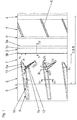
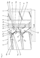
- the Fig. 1 to Fig. 4 each show the one half of a tread of a pneumatic vehicle tire with a profile band 1, a shoulder-side tread area 2, a profile band 1 and the tread area 2 from each other separating circumferential groove 3 and a tread strip 1 inside the tread strip limiting Circumferential groove 4, of which only a partial area can be seen.
- the second tread half is preferably provided with matching profile structures.
- the circumferential groove 3 extending substantially straight in the circumferential direction in the illustrated embodiments has groove flanks 3a, 3b and a groove bottom 3c.
- the circumferential groove 3 in the radial direction has a depth T 1 of preferably 7.5 mm to 8.5 mm, wherein the depth T 1 corresponds to the maximum tread depth provided for the respective pneumatic vehicle tire.
- the circumferential groove 3 has a width B 1 of preferably 6.0 mm to 8.0 mm.
- the groove flank 3a extends at an angle ⁇ of preferably up to 10 ° to the radial direction.
- the groove flank 3b extends at an angle ⁇ of 10 ° to 20 °, preferably of about 14 °, to the radial direction, wherein the angle ⁇ is greater than the angle ⁇ .
- the profile band 1 for example, a relation to the circumferential groove 3 narrower and shallower executed circumferential groove 5 and a plurality of between the two circumferential grooves 4, 5 mutually parallel transverse grooves 6.
- the transverse grooves 6 each extend at an acute angle of preferably up to 45 ° to the circumferential direction.
- the tread outside edge of the tread footprint of the tread is indicated by a circumferential line L 1 .
- the tread region 2 has in the axial direction a width b 1 of 15% to 30%, in particular of approximately 25%, of the width B of the ground contact area, the width B corresponding to the statically determined footprint according to ETRTO standards (load at 70 % of capacity, internal pressure according to load class).
- the tread region 2 comprises a circumferential rib 7 and a shoulder-like tread strip 8 patterned in the form of a block.
- specially designed transverse grooves 9 are provided which each have a main section 10 extending beyond the ground contact surface and two end sections 11, 12 on the tread side.
- adjacent transverse grooves 9 In the circumferential direction adjacent transverse grooves 9 have in the area of their Main sections 10 in the circumferential direction from each other, the usual distances of preferably 20.0 mm to 40.0 mm.
- the main portion 10 extends at least substantially straight and in plan view at an acute angle ⁇ of up to 30 °, in particular of at most 10 ° to the axial direction and terminates at the circumferential rib 7 in a measured distance in the axial direction a 1 of 20.0
- the end portions 11, 12 respectively at the tread inside end of the main portion 10 and give the transverse groove 9 in plan view of a Y-like shape, wherein the circumferential rib 7 in between the End portions 11, 12 of a transverse groove 9 lying areas in plan view in each case protrudes in a triangular shape.
- Each triangular area is bounded to the respective lateral groove 9 on the tread surface by two boundary edges 7a, 7b enclosing an angle ⁇ .
- the angle ⁇ is 60 ° to 120 °, preferably 80 ° to 100 °, and more preferably 85 ° to 95 °.
- the end sections 11, 12 terminate on the inside of the tread strip in each case in a distance a 2 ⁇ a 1 in the axial direction in front of the circumferential groove 3, wherein the distance a 2 is preferably at least 8.0 mm.
- the end sections 11, 12 may also terminate in front of the circumferential groove 3 in particular deviations from one another by up to 3.0 mm.
- Each main section 10 on the tread surface has a width B 2 of 3.0 mm to 6.0 mm, which continuously increases in the embodiments shown in the area of the ground contact area from the outer edge of the main section 10 to the tread inside end of the main section 10.
- Fig. 1 The main section 10 has a continuously decreasing depth in the radial direction in the area which runs off the shoulder, its depth T 2 within the ground contact area amounts to at least 60% of the depth T 1 (FIG. Fig. 5 ) of the circumferential groove 3.
- the main portion 10 is bounded by two groove flanks 10a, 10b and a groove bottom 10c, wherein the groove flanks 10a, 10b each extend at a small angle of, for example, 4 ° to the radial direction.
- the end sections 11, 12 have, as will be explained in more detail below, a specific depth and width profile. According to Fig. 1 to Fig. 4 sits in the end section 11 the Groove flank 10a ( Fig. 6 ) of the main portion 10 to the circumferential rib 7, so that the end portion 11 extends in plan view at least substantially at the angle ⁇ .
- the measured at the tread surface width of the end portion 11, starting from the main portion 10 to the tread inside end of the end portion 11 continuously decreases in particular 30% to 60% of the width B 2 .
- Fig. 7 which shows a longitudinal section aligned in the extension direction of the end section 11, the end section 11 is delimited in the radial direction by a groove bottom 11a and furthermore by an edge 11b extending to the tread surface.
- the groove bottom 11a adjoins the groove bottom 10c of the main portion 10 and extends rampwise at an acute angle ⁇ of 30 ° to 50 °, in particular 35 ° to 45 °, to the radial direction and ends inside the tread in the radial direction at a depth T 3 of 4.0 mm to 5.0 mm.
- the flank 11b adjoins the groove bottom 11a and extends substantially straight and preferably at an angle of up to 5 °, in particular of approximately 2 °, to the radial direction.
- flank 11b can also extend in the radial direction.
- a transition rounding which preferably binds the groove bottom 11a and the edge 11b kink-free together and is rounded in cross-section along a circular arc with a radius of, for example, about 3.0 mm.
- the end portion 12 is inclined with respect to the circumferential direction in opposite directions to the end portion 11 and extends in plan view at an acute angle ⁇ of 30 ° to 70 °, in particular from 40 ° to 55 °, to the axial direction.
- the end portion 12 has at the mouth portion to the main portion 10 on the tread surface in the axial direction, a width B 3 of 20% to 50% of the width B 2 ( Fig. 6 ) of the main section 10.
- the width B 3 starting from the main section 10, decreases continuously, in particular 15% to 30% of the width B 2 of the main section, to the end region of the end section 12 that is at the inner end of the running strip.
- Fig. 8 which shows an extension-oriented longitudinal section through the end portion 12, the end portion 12 in the radial direction by a special shaped groove bottom 12a and further limited by a running to the tread surface short edge 12b.
- the groove bottom 12a is composed in the radial direction of a radially inner portion 12'a, a central portion 12 "a and a radially outer portion 12"'a together.
- the radially inner portion 12'a connects directly to the groove bottom 10c of the main portion 10 and extends at an acute angle ⁇ 'of 20 ° to 60 °, in particular of up to 45 °, to the radial direction to a depth T 4 of FIG , 0 mm to 5.0 mm, preferably about 4.6 mm.
- the middle portion 12 "a adjoins the radially inner portion 12'a, the middle portion 12a" at an acute angle ⁇ " ⁇ 'of 15 ° to 25 °, preferably about 20 ° , to the radial direction, extends to a depth T 5 of 1.5 mm to 2.5 mm, preferably of approximately 2.0 mm,
- the radially outer portion 12 "'a adjoining the central portion 12" a preferably extends at least
- the flank 12b abuts the radially outer portion 12 "'a and extends, as in FIG Fig. 8 shown, in the radial direction or at an angle of in particular up to 5 ° to the radial direction to the tread surface.
- a transitional rounding can be provided between the sections 12'a and 12'a, which preferably binds the two sections 12'a, 12'a to one another without kinking and is rounded in cross section along a circular arc with a radius of, for example, approximately 3.0 mm ,
- each recess 13 is formed in the embodiment shown in plan view substantially in the form of a triangle, so that each recess 13 is bounded in the radial direction by a substantially triangular bottom surface 13 a.
- Each recess 13 is further bounded by adjoining the bottom surface 13a boundary surfaces 13b, 13c.
- boundary surfaces 13b, 13c respectively adjoin a side of the triangle of the bottom surface 13a located inside the circumferential rib 7 and, in the embodiment shown, each extend at an angle of preferably up to 10 ° to the radial direction. However, the boundary surfaces 13b, 13c may also extend in the radial direction.
- Each recess 13 has a length l 1 of 5.0 mm to 15.0 mm, in particular from 7.0 mm to 10.0 mm in extension of the located on the tread surface edge of the circumferential groove 3.
- Each recess 13 further has a maximum width B 4 of 20% to 40%, in particular 25% to 35%, of the width B 1 of the circumferential groove relative to a line extending the respective marginal edge of the circumferential groove 3 located in the axial direction 3 on.
- Fig. 9 is a sectional view, the section line IX-IX at least substantially parallel to one of the sides of the triangle of the bottom surface 13a, shown.
- Fig. 9 is the triangular bottom surface 13a inclined relative to the tread surface, that the recess 13 along one of the lying within the circumferential rib 7 sides of the bottom surface 13a, in the embodiment shown along the side to the boundary surface 13c, in the radial direction of their smallest depth T 6 .
- the depth of the recess 13 increases continuously, so that the recess 13 at its one end in the circumferential direction in the radial direction of its greatest depth T 7 has.
- the depth T 6 is preferably 3.5 mm to 4.5 mm and the depth T 7 is preferably 5.0 mm to 6.0 mm.
- each groove 14 extends at least substantially in the circumferential direction and has a depth in the radial direction of preferably approximately 1.0 mm and at the tread surface has a width of preferably approximately 2.0 mm.
- Fig. 4 shows a further embodiment, in which to Fig. 2 analogous recesses 13 as well Fig. 3 analog grooves 14 and additionally shallow grooves 15, 15 'are provided.
- the grooves 15, 15 ' extend from each second transverse groove 9 at least substantially straight in extension of the respective end portion 11, 12th
- Each groove 15, 15 ' has a depth in the radial direction and a width at the tread surface which is smaller than the width and depth of the groove 14, and preferably 0.5 each mm.
- the end section 11 may extend in plan view at an angle which deviates from the selected angle ⁇ of the main section 10 by up to 5 ° in particular, so that the groove flank 10a (FIG. Fig. 6 ) at the transition of the main portion 10 to the end portion 11 in plan view has a "kink".
- the circumferential rib 7 can in principle be structured with cuts narrow grooves and the like.
Landscapes
- Engineering & Computer Science (AREA)
- Mechanical Engineering (AREA)
- Tires In General (AREA)
Abstract
Description
- Die Erfindung betrifft einen Fahrzeugluftreifen in Radialbauart mit einem Laufstreifen mit einem durch eine Umfangsrille laufstreifeninnenseitig begrenzten schulterseitigen Laufstreifenbereich, welcher 15% bis 30% der Breite der Bodenaufstandsfläche einnimmt und eine an die Umfangsrille angrenzende Umfangsrippe sowie ein durch Querrillen blockartig strukturiertes schulterseitiges Laufstreifenband umfasst, wobei jede Querrille in axialer Richtung in einem Abstand von vorzugsweise mindestens 8,0 mm vor der Umfangsrille endet und wobei jede Querrille einen innerhalb der und über die Bodenaufstandsfläche hinaus verlaufenden Hauptabschnitt aufweist.
- Es ist bekannt und üblich, Laufstreifen von Fahrzeugluftreifen in ihren schulterseitigen Bereichen mit zumindest im Wesentlichen unstrukturierten Umfangsrippen zu versehen. Derartige Umfangsrippen weisen eine hohe Steifigkeit auf, welche beim Fahren eine gute Übertragung von Seitenkräften auf den Untergrund gewährleistet. An diese Umfangsrippen schließt laufstreifenaußenseitig meist ein mit Querrillen blockartig strukturierter Laufstreifenbereich an, welcher infolge der Querrillen gegenüber der Umfangsrippe eine deutlich geringere Steifigkeit aufweist. Die deutlich voneinander abweichenden Steifigkeiten dieser Laufstreifenbereiche können ein ungleichmäßiges Abriebbild des Laufstreifens zur Folge haben. Dabei wird der steifere Laufstreifenbereich zuerst abgefahren. Weniger steife Laufstreifenbereiche können unter Krafteinwirkung leichter nachgeben und werden daher weniger stark abgerieben.
- Der Erfindung liegt daher die Aufgabe zugrunde, einen Fahrzeugluftreifen der eingangs genannten Art derart zu gestalten, dass der Laufstreifenabrieb in den schulterseitigen Laufstreifenbereichen gleichmäßiger wird.
- Die gestellte Aufgabe wird erfindungsgemäß dadurch gelöst, dass jede Querrille zwei jeweils an das laufstreifeninnenseitige Ende ihres Hauptabschnittes anschließende Endabschnitte aufweist, welche der Querrille in Draufsicht eine Y-artige Gestalt verleihen, wobei die Umfangsrippe in die zwischen den Endabschnitten einer Querrille liegenden Bereiche in Draufsicht jeweils dreieckförmig hineinragt.
- Durch die Y-artig gestalteten Querrillen wird das Steifigkeitsniveau der Umfangsrippe des schulterseitigen Laufstreifenbereiches an jenes des an die Umfangsrippe angrenzenden blockartig strukturierten Laufstreifenbandes gut angenähert. Laufstreifen mit erfindungsgemäßen Querrillen weisen in ihren schulterseitigen Bereichen daher eine weitgehend homogene Steifigkeitsverteilung auf, wodurch das Abriebbild des Laufstreifens wesentlich gleichmäßiger wird. Zusätzlich begünstigen die erfindungsgemäß ausgeführten Querrillen beim Fahren auf nasser Fahrbahn die Aquaplaningeigenschaften, da Wasser aus dem Bereich der Umfangsrippe über die beiden laufstreifeninnseitigen Endabschnitte der Querrillen besonders effektiv zum Hauptabschnitt und damit über die Bodenaufstandsfläche hinaus geleitet werden kann.
- Bei einer besonders vorteilhaften Ausführungsform der Erfindung endet der Hauptabschnitt in axialer Richtung in einem Abstand von 20,0 mm bis 30,0 mm vor der die Umfangsrippe laufstreifeninnenseitig begrenzenden Umfangsrille. Diese Maßnahme ist für einen besonders sanften Übergang der Steifigkeitsniveaus zwischen jenem Bereich, der blockartig strukturiert ist und jenem, der eine Umfangsrippe bildet, von Vorteil.
- Bei einer weiteren, besonders bevorzugten Ausführung sind die beiden Endabschnitte bezüglich der Umfangsrichtung des Laufstreifens gegensinnig geneigt. Auch diese Maßnahme ist für eine Optimierung des Steifigkeitsverlaufes von Vorteil und begünstigt ein gutes Wasserdrainagevermögen der Querrillen. Besonders günstig ist dabei, wenn die beiden Endabschnitte in axialer Richtung in im Wesentlichen gleich großen Abständen vor der die Umfangsrippe laufstreifeninnenseitig begrenzenden Umfangsrille enden.
- In diesem Zusammenhang ist es ferner vorteilhaft, wenn gemäß der Erfindung jeder dreieckige Bereich der Umfangsrippe an der Laufstreifenoberfläche zur jeweiligen Querrille durch zwei Begrenzungskanten begrenzt ist, welche einen Winkel einschließen, der 60° bis 120°, vorzugsweise 80° bis 100° und besonders bevorzugt 85° bis 95°, beträgt.
- Für die Aquaplaningeigenschaften des Laufstreifens ist es ferner besonders vorteilhaft, wenn die Tiefe jedes Endabschnittes zum laufstreifeninnenseitigen Ende abnimmt und wenn sich einer der Endabschnitte zumindest im Wesentlichen in Fortsetzung des Hauptabschnittes erstreckt.
- Besondere Details der Ausgestaltung des zumindest im Wesentlichen in Fortsetzung des Hauptabschnittes verlaufenden Endabschnittes sind für eine Optimierung des Aquaplaningverhaltens besonders vorteilhaft. Bei einer dieser Maßnahmen ist vorgesehen, dass dieser Endabschnitt in seiner Erstreckungsrichtung einen unter einem Winkel von 30° bis 50°, insbesondere von 35° bis 45°, zur radialen Richtung verlaufenden Rillengrund aufweist, welcher Richtung Endabschnittende ansteigt. Die Tiefe des Endabschnittes am laufstreifeninnenseitigen Ende des Rillengrundes beträgt 4,0 mm bis 5,0 mm. Eine weitere, vorteilhafte Maßnahme besteht darin, dass am laufstreifeninnenseitigen Ende dieses Endabschnittes zwischen dem Rillengrund und der Laufstreifenoberfläche eine Flanke verläuft, welche zur radialen Richtung unter einem Winkel von bis zu 5°, insbesondere von bis zu 2°, verläuft.
- Der zweite Endabschnitt wird bevorzugt ebenfalls besonders ausgestaltet, um eine optimale Wasserableitung zu gewährleisten. Insbesondere weist der Rillengrund dieses Endabschnittes einen besonderen Verlauf zwischen dem Hauptabschnitt und seinem Ende auf. Der Rillengrund verläuft entlang mehrerer Abschnitte, insbesondere weist er einen an den Hauptabschnitt anschließenden radial inneren Abschnitt, einen mittleren Abschnitt und einen radial äußeren Abschnitt auf, wobei der radial innere Abschnitt unter einem Winkel von 20° bis 60°, insbesondere bis zu 45°, und der mittlere Abschnitt unter einem Winkel von 15° bis 25°, vorzugsweise bis zu 20°, zur radialen Richtung verläuft. Der radial äußere Abschnitt verläuft in einer Tiefe von 1,5 mm bis 2,5 mm, vorzugsweise von 3,0 mm, und zumindest im Wesentlichen parallel zur Laufstreifenoberfläche.
- Bei einer weiteren Ausführungsvariante der Erfindung ist die Umfangsrippe entlang der Umfangsrille mit Aussparungen versehen, welche den Querrillen zumindest im Wesentlichen gegenüberliegen und in Draufsicht jeweils im Wesentlichen in Form eines Dreieckes ausgebildet sind. Auch diese Aussparungen sind für den erwünschten Steifigkeitsverlauf im erfindungsgemäß gestalteten Laufstreifenbereich von Vorteil. Besonders bevorzugt ist eine Ausführung, bei der jede Aussparung eine in Draufsicht im Wesentlichen dreieckige Bodenfläche aufweist, welche gegenüber der Laufstreifenoberfläche geneigt ist, wobei die Aussparung entlang der einen, innerhalb der Umfangsrippe liegenden Seite der Bodenfläche in radialer Richtung ihre geringste Tiefe, welche 3,5 mm bis 4,5 mm beträgt, aufweist.
- Weitere Merkmale, Vorteile und Einzelheiten der Erfindung werden nun anhand der Zeichnung, die schematisch mehrere Ausführungsbeispiele der Erfindung darstellt, näher beschrieben. Dabei zeigen
-
Fig. 1 bis Fig. 4 Draufsichten auf einen Ausschnitt eines Laufstreifens eines Fahrzeugluftreifens mit je einer Ausführungsvariante gemäß der Erfindung, -
Fig. 5 bis Fig. 8 Schnittdarstellungen entlang der Linien V-V bis VIII-VIII derFig. 1 bis Fig. 4 und -
Fig. 9 eine Schnittdarstellung entlang der Linie IX-IX derFig. 2 bzw. derFig. 4 . - Die Erfindung befasst sich mit speziell gestalteten schulterseitigen Laufstreifenbereichen von Fahrzeugluftreifen in Radialbauart, insbesondere von Van-Reifen, vorzugsweise von Wohnmobilreifen ("Camperreifen").
- Die
Fig. 1 bis Fig. 4 zeigen jeweils die eine Hälfte eines Laufstreifens eines Fahrzeugluftreifens mit einem Profilband 1, einem schulterseitigen Laufstreifenbereich 2, einer das Profilband 1 und den Laufstreifenbereich 2 voneinander trennenden Umfangsrille 3 sowie einer das Profilband 1 laufstreifeninnenseitig begrenzenden Umfangsrille 4, von welcher nur ein Teilbereich zu sehen ist. Die zweite Laufstreifenhälfte ist vorzugsweise mit übereinstimmenden Profilstrukturen versehen. - Die bei den gezeigten Ausführungsvarianten im Wesentlichen gerade in Umfangsrichtung verlaufende Umfangsrille 3 weist Rillenflanken 3a, 3b und einen Rillengrund 3c auf. Gemäß
Fig. 5 weist die Umfangsrille 3 in radialer Richtung eine Tiefe T1 von vorzugsweise 7,5 mm bis 8,5 mm auf, wobei die Tiefe T1 der für den jeweiligen Fahrzeugluftreifen vorgesehenen maximalen Profiltiefe entspricht. An der Laufstreifenoberfläche weist die Umfangsrille 3 eine Breite B1 von vorzugsweise 6,0 mm bis 8,0 mm auf. Die Rillenflanke 3a verläuft unter einem Winkel α von vorzugsweise bis zu 10° zur radialen Richtung. Die Rillenflanke 3b verläuft unter einem Winkel β von 10° bis 20°, vorzugsweise von etwa 14°, zur radialen Richtung, wobei der Winkel β größer ist als der Winkel α. - Wie
Fig. 1 bis Fig. 4 zeigen, weist das Profilband 1 beispielsweise eine gegenüber der Umfangrille 3 schmäler und seichter ausgeführte Umfangsrille 5 sowie eine Vielzahl von zwischen den beiden Umfangsrille 4, 5 parallel zueinander verlaufender Querrillen 6 auf. Die Querrillen 6 verlaufen jeweils unter einem spitzen Winkel von vorzugsweise bis zu 45° zur Umfangsrichtung. - Der laufstreifenaußenseitige Rand der Bodenaufstandsfläche des Laufstreifens ist durch eine in Umfangsrichtung verlaufende Linie L1 gekennzeichnet. Innerhalb der Bodenaufstandsfläche weist der Laufstreifenbereich 2 in axialer Richtung eine Breite b1 von 15% bis 30%, insbesondere von etwa 25%, der Breite B der Bodenaufstandsfläche auf, wobei die Breite B dem statisch ermittelten Footprint gemäß E.T.R.T.O.-Standards (Last bei 70% der Tragfähigkeit, Innendruck je nach Tragfähigkeitsklasse) entspricht.
- Der Laufstreifenbereich 2 umfasst eine Umfangsrippe 7 und ein blockartig strukturiertes schulterseitiges Laufstreifenband 8. Im Laufstreifenbereich 2 sind speziell gestaltete Querrillen 9 vorgesehen, welche jeweils einen auch über die Bodenaufstandsfläche hinausverlaufenden Hauptabschnitt 10 und zwei laufstreifeninnenseitige Endabschnitte 11, 12 aufweisen. In Umfangsrichtung benachbarte Querrillen 9 weisen im Bereich ihrer Hauptabschnitte 10 in Umfangsrichtung voneinander die üblichen Abstände von vorzugsweise 20,0 mm bis 40,0 mm auf.
- Der Hauptabschnitt 10 verläuft zumindest im Wesentlichen gerade sowie in Draufsicht unter einem spitzen Winkel γ von bis zu 30°, insbesondere von höchstens 10°, zur axialen Richtung und endet an der Umfangsrippe 7 in einem in axialer Richtung gemessenen Abstand a1 von 20,0 mm bis 30,0 mm vor der die Umfangsrippe 7 begrenzenden Umfangsrille 3. Die Endabschnitte 11, 12 schließen jeweils am laufstreifeninnenseitigen Ende des Hauptabschnittes 10 an und verleihen der Querrille 9 in Draufsicht eine Y-artige Gestalt, wobei die Umfangsrippe 7 in die zwischen den Endabschnitten 11, 12 einer Querrille 9 liegenden Bereiche in Draufsicht jeweils dreieckförmig hineinragt. Jeder dreieckförmige Bereich ist zur jeweiligen Querrille 9 an der Laufstreifenoberfläche durch zwei einen Winkel λ einschließende Begrenzungskanten 7a, 7b begrenzt. Der Winkel λ, beträgt 60° bis 120°, vorzugsweise 80° bis 100°, und besonders bevorzugt 85° bis 95°. Die Endabschnitte 11, 12 enden laufstreifeninnenseitig jeweils in einem in axialer Richtung vorliegenden Abstand a2 < a1 vor der Umfangsrille 3, wobei der Abstand a2 vorzugsweise mindestens 8,0 mm beträgt. Die Endabschnitte 11, 12 können auch in insbesondere um bis zu 3,0 mm voneinander abweichenden Abständen vor der Umfangsrille 3 enden.
- Gemäß
Fig. 6 weist jeder Hauptabschnitt 10 an der Laufstreifenoberfläche eine Breite B2 von 3,0 mm bis 6,0 mm auf, welche bei den gezeigten Ausführungsvarianten im Bereich der Bodenaufstandsfläche vom laufstreifenaußenseitigen Ende des Hauptabschnittes 10 zum laufstreifeninnseitigen Ende des Hauptabschnittes 10 kontinuierlich zunimmt (Fig. 1 ). Der Hauptabschnitt 10 weist im schulterseitig auslaufenden Bereich in radialer Richtung eine kontinuierlich geringer werdende Tiefe auf, innerhalb der Bodenaufstandsfläche beträgt seine Tiefe T2 zumindest 60% der Tiefe T1 (Fig. 5 ) der Umfangsrille 3. Der Hauptabschnitt 10 ist durch zwei Rillenflanken 10a, 10b und einen Rillengrund 10c begrenzt, wobei die Rillenflanken 10a, 10b jeweils unter einem kleinen Winkel von beispielsweise 4° zur radialen Richtung verlaufen. - Die Endabschnitte 11, 12 weisen, wie nachfolgend genauer erläutert wird, einen speziellen Tiefen- und Breitenverlauf auf. Gemäß
Fig. 1 bis Fig. 4 setzt sich im Endabschnitt 11 die Rillenflanke 10a (Fig. 6 ) des Hauptabschnittes 10 bis zur Umfangsrippe 7 fort, sodass sich der Endabschnitt 11 in Draufsicht zumindest im Wesentlichen unter dem Winkel γ erstreckt. Die an der Laufstreifenoberfläche gemessene Breite des Endabschnittes 11 nimmt ausgehend vom Hauptabschnitt 10 bis zum laufstreifeninnenseitigen Ende des Endabschnittes 11 kontinuierlich auf insbesondere 30% bis 60% der Breite B2 ab. - Gemäß
Fig. 7 , welche einen in Erstreckungsrichtung des Endabschnittes 11 ausgerichtete Längsschnitt zeigt, ist der Endabschnitt 11 in radialer Richtung durch einen Rillengrund 11a sowie ferner durch eine zur Laufstreifenoberfläche verlaufende Flanke 11b begrenzt. Der Rillengrund 11a schließt an den Rillengrund 10c des Hauptabschnittes 10 an und verläuft rampenartig unter einem spitzen Winkel ε von 30° bis 50°, insbesondere von 35° bis 45°, zur radialen Richtung und endet laufstreifeninnenseitig in radialer Richtung in einer Tiefe T3 von 4,0 mm bis 5,0 mm. In der Tiefe T3 schließt die Flanke 11b an den Rillengrund 11a an und verläuft im Wesentlichen gerade sowie vorzugsweise unter einem Winkel von bis zu 5°, insbesondere von etwa 2°, zur radialen Richtung. Alternativ kann die Flanke 11b auch in radialer Richtung verlaufen. Ferner kann, wie inFig. 7 gezeigt, zwischen dem Rillengrund 11a und der Flanke 11b eine Übergangsrundung vorgesehen sein, welche den Rillengrund 11a und die Flanke 11b vorzugsweise knickfrei aneinander anbindet und im Querschnitt entlang eines Kreisbogens mit einem Radius von beispielsweise zirka 3,0 mm gerundet ist. - Wie
Fig. 1 bis Fig. 4 zeigen, ist der Endabschnitt 12 bezüglich der Umfangsrichtung gegensinnig zum Endabschnitt 11 geneigt und erstreckt sich in Draufsicht unter einem spitzen Winkel δ von 30° bis 70°, insbesondere von 40° bis 55°, zur axialen Richtung. Der Endabschnitt 12 weist am Mündungsbereich zum Hauptabschnitt 10 an der Laufstreifenoberfläche in axialer Richtung eine Breite B3 von 20% bis 50% der Breite B2 (Fig. 6 ) des Hauptabschnittes 10 auf. Die Breite B3 nimmt ausgehend vom Hauptabschnitt 10 zum laufstreifeninnseitigen Endbereich des Endabschnittes 12 kontinuierlich auf insbesondere 15% bis 30% der Breite B2 des Hauptabschnittes ab. - Gemäß
Fig. 8 , welche einen in Erstreckungsrichtung ausgerichteten Längsschnitt durch den Endabschnitt 12 zeigt, ist der Endabschnitt 12 in radialer Richtung durch einen speziell gestalteten Rillengrund 12a sowie ferner durch eine zur Laufstreifenoberfläche verlaufende kurze Flanke 12b begrenzt. Der Rillengrund 12a setzt sich in radialer Richtung aus einem radial inneren Abschnitt 12'a, einem mittleren Abschnitt 12"a und einem radial äußeren Abschnitt 12"'a zusammen. Der radial innere Abschnitt 12'a schließt unmittelbar an den Rillengrund 10c des Hauptabschnittes 10 an und verläuft unter einem spitzen Winkel ϕ' von 20° bis 60°, insbesondere von bis zu 45°, zur radialen Richtung bis in eine Tiefe T4 von 4,0 mm bis 5,0 mm, vorzugsweise von in etwa 4,6 mm. In der Tiefe T4 schließt der mittlere Abschnitt 12"a an den radial inneren Abschnitt 12'a an, wobei der mittlere Abschnitt 12a" unter einem spitzen Winkel ϕ" < ϕ' von 15° bis 25°, vorzugsweise von in etwa 20°, zur radialen Richtung bis in eine Tiefe T5 von 1,5 mm bis 2,5 mm, vorzugsweise von etwa 2,0 mm, verläuft. Der an den mittleren Abschnitt 12"a anschließende radial äußere Abschnitt 12"'a verläuft vorzugsweise zumindest im Wesentlichen parallel zur Laufstreifenoberfläche. Die Flanke 12b schließt an den radial äußeren Abschnitt 12"'a an und verläuft, wie inFig. 8 gezeigt, in radialer Richtung oder unter einem Winkel von insbesondere bis zu 5° zur radialen Richtung zur Laufstreifenoberfläche. Ferner kann zwischen den Abschnitten 12'a und 12"a eine Übergangsrundung vorgesehen sein, welche die beiden Abschnitte 12'a, 12"a vorzugsweise knickfrei aneinander anbindet und im Querschnitt entlang eines Kreisbogens mit einem Radius von beispielsweise zirka 3,0 mm gerundet ist. - Bei der Ausführungsvariante gemäß
Fig. 2 ist die Umfangsrippe 7 entlang der Umfangsrille 3 zusätzlich mit Aussparungen 13 versehen, wobei die Aussparungen 13 in axialer Richtung im Wesentlichen jeweils den Endabschnitten 12 der Querrillen 9 gegenüberliegen. Jede Aussparung 13 ist bei der gezeigten Ausführungsvariante in Draufsicht im Wesentlichen in Form eines Dreieckes ausgebildet, sodass jede Aussparung 13 in radialer Richtung durch eine im Wesentlichen dreieckige Bodenfläche 13a begrenzt ist. Jede Aussparung 13 ist ferner durch an die Bodenfläche 13a anschließende Begrenzungsflächen 13b, 13c begrenzt. Die Begrenzungsflächen 13b, 13c schließen jeweils an eine innerhalb der Umfangsrippe 7 liegende Seite des Dreieckes der Bodenfläche 13a an und verlaufen bei der gezeigten Ausführungsvariante jeweils unter einem Winkel von vorzugsweise bis zu 10° zur radialen Richtung. Die Begrenzungsflächen 13b, 13c können jedoch auch in radialer Richtung verlaufen. - Jede Aussparung 13 weist in Verlängerung der an der Laufstreifenoberfläche befindlichen Randkante der Umfangsrille 3 eine Länge l1 von 5,0 mm bis 15,0 mm, insbesondere von 7,0 mm bis 10,0 mm, auf. Jede Aussparung 13 weist ferner bezogen auf eine Linie in Verlängerung der an der Laufstreifenoberfläche befindlichen jeweiligen Randkante der Umfangsrille 3 in axialer Richtung eine maximale Breite B4 von 20% bis 40%, insbesondere von 25% bis 35%, der Breite B1 der Umfangsrille 3 auf.
- In
Fig. 9 ist eine Schnittdarstellung, deren Schnittlinie IX-IX zumindest im Wesentlichen parallel zu einer der Seiten des Dreieckes der Bodenfläche 13a verläuft, gezeigt. GemäßFig. 9 ist die dreieckige Bodenfläche 13a derart gegenüber der Laufstreifenoberfläche geneigt, dass die Aussparung 13 entlang einer der innerhalb der Umfangsrippe 7 liegenden Seiten der Bodenfläche 13a, bei der gezeigten Ausführungsvariante entlang der Seite zur Begrenzungsfläche 13c, in radialer Richtung ihre kleinste Tiefe T6 aufweist. Entlang der anderen innerhalb der Umfangsrippe 7 liegenden Seite der Bodenfläche 13a, bei der gezeigten Ausführungsvariante entlang der Seite zur Begrenzungsfläche 13b, nimmt die Tiefe der Aussparung 13 kontinuierlich zu, sodass die Aussparung 13 an ihrem einen in Umfangsrichtung liegenden Ende in radialer Richtung ihrer größte Tiefe T7 aufweist. Die Tiefe T6 beträgt vorzugsweise 3,5 mm bis 4,5 mm und die Tiefe T7 beträgt vorzugsweise 5,0 mm bis 6,0 mm. - Die in
Fig. 3 gezeigte Ausführungsvariante unterscheidet sich von jener gemäßFig. 1 dadurch, dass zwischen den laufstreifeninnenseitigen Enden der Endabschnitte 11, 12 von zwei in Umfangsrichtung benachbarten Querrillen 9 jeweils eine seichte Nut 14 vorgesehen ist. Jede Nut 14 verläuft zumindest im Wesentlichen in Umfangsrichtung und weist in radialer Richtung eine Tiefe von vorzugsweise in etwa 1,0 mm und an der Laufstreifenoberfläche eine Breite von vorzugsweise in etwa 2,0 mm auf. -
Fig. 4 zeigt eine weitere Ausführungsvariante, bei welcher zuFig. 2 analoge Aussparungen 13 sowie zuFig. 3 analoge Nuten 14 und zusätzlich seichte Nuten 15, 15' vorgesehen sind. Die Nuten 15, 15' erstrecken sich ausgehend von jeder zweiten Querrille 9 zumindest im Wesentlichen gerade in Verlängerung des jeweiligen Endabschnittes 11, 12 unter deren jeweiligen Winkeln γ, δ bis zur Umfangsrille 3. Jede Nut 15, 15' weist in radialer Richtung eine Tiefe und an der Laufstreifenoberfläche eine Breite auf, welche jeweils kleiner als die Breite und Tiefe der Nut 14 ist und vorzugsweise jeweils 0,5 mm beträgt. - Bei weiteren Ausführungsvarianten kann sich der Endabschnitt 11 in Draufsicht unter einem Winkel, welcher gegenüber dem gewählten Winkel γ des Hauptabschnittes 10 um insbesondere bis zu 5° abweicht, erstrecken, sodass die Rillenflanke 10a (
Fig. 6 ) am Übergang des Hauptabschnittes 10 zum Endabschnitt 11 in Draufsicht einen "Knick" aufweist. Die Umfangsrippe 7 kann grundsätzlich mit Einschnitten schmalen Rillen und dergleichen strukturiert sein. -
- 1....................................
- rofilband
- 2....................................
- aufstreifenbereich
- 3....................................
- mfangsrille
- 3a, 3b............................
- illenflanke
- 3c..................................
- illengrund
- 4....................................
- mfangsrille
- 5....................................
- mfangsrille
- 6....................................
- uenrrille
- 7....................................
- mfangsrippe
- 7a, 7b............................
- Begrenzungskante
- 8....................................
- Laufstreifenband
- 9....................................
- Queirrille
- 10..................................
- Hauptabschnitt
- 10a, 10b........................
- Rillenflanke
- 10c................................
- Rillengrund
- 11, 12............................
- Endabschnitt
- 11a, 12a........................
- Rillengrund
- 11b, 12b........................
- Flanke
- 12a', 12a", 12a"'.........
- Abschnitt
- 13..................................
- Aussparung
- 13a................................
- Bodenfläche
- 13b, 13c ........................
- Begrenzungsfläche
- 14,15,15'.....................
- Nut
- a1,a2..............................
- Abstand
- b1...................................
- Breite
- B...................................
- Breite
- Bi.i=1-4...........................
- Breite
- L1..................................
- Linie
- l1....................................
- Länge
- Ti,i=1-7............................
- Tiefe
- α, β, γ, δ, ε, λ, ϕ, ϕ"....
- Winkel
Claims (14)
- Fahrzeugluftreifen in Radialbauart mit einem Laufstreifen mit einem durch eine Umfangsrille (3) laufstreifeninnenseitig begrenzten schulterseitigen Laufstreifenbereich (2), welcher 15% bis 30% der Breite (B) der Bodenaufstandsfläche einnimmt und eine an die Umfangsrille (3) angrenzende Umfangsrippe (7) sowie ein durch Querrillen (9) blockartig strukturiertes schulterseitiges Laufstreifenband (8) umfasst, wobei jede Querrille (9) in axialer Richtung in einem Abstand (a2) von vorzugsweise mindestens 8,0 mm vor der Umfangsrille (3) endet und wobei jede Querrille (4) einen innerhalb der und über die Bodenaufstandsfläche hinaus verlaufenden Hauptabschnitt (10) aufweist,
dadurch gekennzeichnet,
dass jede Querrille (9) zwei jeweils an das laufstreifeninnenseitige Ende ihres Hauptabschnittes (10) anschließende Endabschnitte (11, 12) aufweist, welche der Querrille (9) in Draufsicht eine Y-artige Gestalt verleihen, wobei die Umfangsrippe (7) in die zwischen den Endabschnitten (11, 12) einer Querrille (9) liegenden Bereiche in Draufsicht jeweils dreieckförmig hineinragt. - Fahrzeugluftreifen nach Anspruch 1, dadurch gekennzeichnet, dass der Hauptabschnitt (10) in axialer Richtung in einem Abstand (a1) von 20,0 mm bis 30,0 mm vor der die Umfangsrippe (7) laufstreifeninnenseitig begrenzenden Umfangsrille (3) endet.
- Fahrzeugluftreifen nach Anspruch 1 oder 2, dadurch gekennzeichnet, dass die Endabschnitte (11, 12) bezüglich der Umfangsrichtung gegensinnig geneigt sind.
- Fahrzeugluftreifen nach einem der Ansprüche 1 bis 3, dadurch gekennzeichnet, dass jeder dreieckförmige Bereich der Umfangsrippe (7) an der Laufstreifenoberfläche zur jeweiligen Querrille (9) durch zwei Begrenzungskanten (7a, 7b) begrenzt ist, welche einen Winkel (λ), der 60° bis 120°, vorzugsweise 80° bis 100°, und besonders bevorzugt 85° bis 95°, beträgt, einschließen.
- Fahrzeugluftreifen nach einem der Ansprüche 1 bis 4, dadurch gekennzeichnet, dass die beiden Endabschnitte (11, 12) in axialer Richtung in im Wesentlichen gleich großen Abständen (a2) vor der die Umfangsrippe (7) laufstreifeninnenseitig begrenzenden Umfangsrille (3) enden.
- Fahrzeugluftreifen nach einem der Ansprüche 1 bis 5, dadurch gekennzeichnet, dass die Tiefe jedes Endabschnittes (11, 12) zum laufstreifeninnenseitigen Ende abnimmt.
- Fahrzeugluftreifen nach einem der Ansprüche 1 bis 6, dadurch gekennzeichnet, dass sich einer der Endabschnitte (11) zumindest im Wesentlichen in Fortsetzung des Hauptabschnittes (10) erstreckt.
- Fahrzeugluftreifen nach Anspruch 7, dadurch gekennzeichnet, dass der sich zumindest im Wesentlichen in Fortsetzung des Hauptabschnittes (10) erstreckende Endabschnitt (11) einen unter einem Winkel (ε) von 30° bis 50°, insbesondere von 35° bis 45°, zur radialen Richtung verlaufenden Rillengrund (11a) aufweist, welcher Richtung Endabschnittende ansteigt.
- Fahrzeugluftreifen nach Anspruch 8, dadurch gekennzeichnet, dass die Tiefe (T3) am laufstreifeninnseitigen Ende des Rillengrundes (11a) 4,0 mm bis 5,0 mm beträgt.
- Fahrzeugluftreifen nach einem der Ansprüche 7 bis 9, dadurch gekennzeichnet, dass der sich zumindest im Wesentlichen in Fortsetzung des Hauptabschnittes (10) erstreckende Endabschnitt (11) eine an das laufstreifeninnseitige Ende des Rillengrundes (11a) anschließende Flanke (11b) aufweist, welche zur radialer Richtung unter einem Winkel von bis zu 5°, insbesondere von bis zu 2°, verläuft.
- Fahrzeugluftreifen nach einem der Ansprüche 1 bis 10, dadurch gekennzeichnet dass der andere Endabschnitt (12) einen Rillengrund (12a) mit einem an den Rillengrund (10c) des Hauptabschnittes (10) anschließenden radial inneren Abschnitt (12'a), einen mittleren Abschnitt (12"a) und einen radial äußeren Abschnitt (12"'a) aufweist, wobei der radial innere Abschnitt (12a') unter einem Winkel (ϕ') von 20° bis 60°, insbesondere bis zu 45°, und der mittlere Abschnitt (12"a) unter einem Winkel (ϕ") von 15° bis 25°, vorzugsweise bis zu 20°, zur radialen Richtung verläuft.
- Fahrzeugluftreifen nach Anspruch 11, dadurch gekennzeichnet, dass der radial äußere Abschnitt (12"'a) in einer Tiefe (T5) von 1,5 mm bis 2,5 mm, vorzugsweise von 2,0 mm, zumindest im Wesentlichen parallel zur Laufstreifenoberfläche verläuft.
- Fahrzeugluftreifen nach einem der Ansprüche 1 bis 12, dadurch gekennzeichnet, dass die Umfangsrippe (7) entlang der Umfangsrille (3) mit Aussparungen (13) versehen ist, welche den Querrillen (10) gegenüberliegen und in Draufsicht jeweils im Wesentlichen in Form eines Dreieckes ausgebildet sind.
- Fahrzeugluftreifen nach Anspruch 13, dadurch gekennzeichnet, dass jede Aussparung (13) eine in Draufsicht im Wesentlichen dreieckige Bodenfläche (13a) aufweist, welche gegenüber der Laufstreifenoberfläche geneigt ist, wobei die Aussparung (13) entlang der einen innerhalb der Umfangsrippe (7) liegenden Seite der Bodenfläche (13a) in radialer Richtung ihre geringste Tiefe, welche 3,5 mm bis 4,5 mm beträgt, aufweist.
Applications Claiming Priority (1)
| Application Number | Priority Date | Filing Date | Title |
|---|---|---|---|
| DE102015214000.8A DE102015214000A1 (de) | 2015-07-24 | 2015-07-24 | Fahrzeugluftreifen |
Publications (2)
| Publication Number | Publication Date |
|---|---|
| EP3130484A1 true EP3130484A1 (de) | 2017-02-15 |
| EP3130484B1 EP3130484B1 (de) | 2018-05-16 |
Family
ID=55451121
Family Applications (1)
| Application Number | Title | Priority Date | Filing Date |
|---|---|---|---|
| EP16158362.0A Active EP3130484B1 (de) | 2015-07-24 | 2016-03-03 | Fahrzeugluftreifen |
Country Status (2)
| Country | Link |
|---|---|
| EP (1) | EP3130484B1 (de) |
| DE (1) | DE102015214000A1 (de) |
Citations (4)
| Publication number | Priority date | Publication date | Assignee | Title |
|---|---|---|---|---|
| EP2522531A1 (de) * | 2011-05-12 | 2012-11-14 | Sumitomo Rubber Industries Limited | Luftreifen |
| EP2586628A2 (de) * | 2011-10-27 | 2013-05-01 | Sumitomo Rubber Industries, Ltd. | Luftreifen |
| DE102012109712A1 (de) * | 2012-10-11 | 2014-04-17 | Continental Reifen Deutschland Gmbh | Fahrzeugluftreifen |
| WO2015059851A1 (ja) * | 2013-10-23 | 2015-04-30 | 株式会社ブリヂストン | 空気入りタイヤ |
-
2015
- 2015-07-24 DE DE102015214000.8A patent/DE102015214000A1/de not_active Withdrawn
-
2016
- 2016-03-03 EP EP16158362.0A patent/EP3130484B1/de active Active
Patent Citations (4)
| Publication number | Priority date | Publication date | Assignee | Title |
|---|---|---|---|---|
| EP2522531A1 (de) * | 2011-05-12 | 2012-11-14 | Sumitomo Rubber Industries Limited | Luftreifen |
| EP2586628A2 (de) * | 2011-10-27 | 2013-05-01 | Sumitomo Rubber Industries, Ltd. | Luftreifen |
| DE102012109712A1 (de) * | 2012-10-11 | 2014-04-17 | Continental Reifen Deutschland Gmbh | Fahrzeugluftreifen |
| WO2015059851A1 (ja) * | 2013-10-23 | 2015-04-30 | 株式会社ブリヂストン | 空気入りタイヤ |
Also Published As
| Publication number | Publication date |
|---|---|
| EP3130484B1 (de) | 2018-05-16 |
| DE102015214000A1 (de) | 2017-01-26 |
Similar Documents
| Publication | Publication Date | Title |
|---|---|---|
| DE69611341T2 (de) | Kraftfahrzeug-Luftreifen mit einem Laufflächenprofil besonders geeignet zum Laufen auf schneebedeckten Strassenoberflächen | |
| EP3589501B1 (de) | Fahrzeugluftreifen | |
| EP3388256B1 (de) | Fahrzeugluftreifen | |
| EP3124290B1 (de) | Fahrzeugluftreifen | |
| EP2906435B1 (de) | Fahrzeugluftreifen | |
| EP3300926B1 (de) | Fahrzeugluftreifen | |
| EP3181378A1 (de) | Fahrzeugluftreifen | |
| WO2019115036A1 (de) | Nutzfahrzeugreifen | |
| EP3519208B1 (de) | Fahrzeugluftreifen | |
| EP4577416A1 (de) | Fahrzeugluftreifen | |
| EP3551477B1 (de) | Fahrzeugluftreifen | |
| DE102019206654A1 (de) | Fahrzeugluftreifen | |
| EP3628511B1 (de) | Fahrzeugluftreifen | |
| EP3750723B1 (de) | Fahrzeugluftreifen | |
| DE102015202615A1 (de) | Fahrzeugluftreifen | |
| EP2138329B1 (de) | Laufflächenprofil für einen Fahrzeugluftreifen | |
| EP3450213A1 (de) | Fahrzeugluftreifen | |
| EP3224060B1 (de) | Fahrzeugluftreifen | |
| EP3160775B1 (de) | Fahrzeugluftreifen | |
| EP3560735B1 (de) | Nutzfahrzeugreifen | |
| EP2138328B1 (de) | Fahrzeugluftreifen | |
| EP3300925B1 (de) | Fahrzeugluftreifen | |
| EP3888949B1 (de) | Fahrzeugluftreifen | |
| EP3130484B1 (de) | Fahrzeugluftreifen | |
| EP3686034B1 (de) | Fahrzeugluftreifen |
Legal Events
| Date | Code | Title | Description |
|---|---|---|---|
| PUAI | Public reference made under article 153(3) epc to a published international application that has entered the european phase |
Free format text: ORIGINAL CODE: 0009012 |
|
| STAA | Information on the status of an ep patent application or granted ep patent |
Free format text: STATUS: THE APPLICATION HAS BEEN PUBLISHED |
|
| AK | Designated contracting states |
Kind code of ref document: A1 Designated state(s): AL AT BE BG CH CY CZ DE DK EE ES FI FR GB GR HR HU IE IS IT LI LT LU LV MC MK MT NL NO PL PT RO RS SE SI SK SM TR |
|
| AX | Request for extension of the european patent |
Extension state: BA ME |
|
| STAA | Information on the status of an ep patent application or granted ep patent |
Free format text: STATUS: REQUEST FOR EXAMINATION WAS MADE |
|
| 17P | Request for examination filed |
Effective date: 20170816 |
|
| RBV | Designated contracting states (corrected) |
Designated state(s): AL AT BE BG CH CY CZ DE DK EE ES FI FR GB GR HR HU IE IS IT LI LT LU LV MC MK MT NL NO PL PT RO RS SE SI SK SM TR |
|
| GRAP | Despatch of communication of intention to grant a patent |
Free format text: ORIGINAL CODE: EPIDOSNIGR1 |
|
| STAA | Information on the status of an ep patent application or granted ep patent |
Free format text: STATUS: GRANT OF PATENT IS INTENDED |
|
| INTG | Intention to grant announced |
Effective date: 20171026 |
|
| GRAS | Grant fee paid |
Free format text: ORIGINAL CODE: EPIDOSNIGR3 |
|
| GRAA | (expected) grant |
Free format text: ORIGINAL CODE: 0009210 |
|
| STAA | Information on the status of an ep patent application or granted ep patent |
Free format text: STATUS: THE PATENT HAS BEEN GRANTED |
|
| AK | Designated contracting states |
Kind code of ref document: B1 Designated state(s): AL AT BE BG CH CY CZ DE DK EE ES FI FR GB GR HR HU IE IS IT LI LT LU LV MC MK MT NL NO PL PT RO RS SE SI SK SM TR |
|
| REG | Reference to a national code |
Ref country code: GB Ref legal event code: FG4D Free format text: NOT ENGLISH |
|
| REG | Reference to a national code |
Ref country code: CH Ref legal event code: EP |
|
| REG | Reference to a national code |
Ref country code: IE Ref legal event code: FG4D Free format text: LANGUAGE OF EP DOCUMENT: GERMAN |
|
| REG | Reference to a national code |
Ref country code: DE Ref legal event code: R096 Ref document number: 502016001054 Country of ref document: DE |
|
| REG | Reference to a national code |
Ref country code: AT Ref legal event code: REF Ref document number: 999197 Country of ref document: AT Kind code of ref document: T Effective date: 20180615 |
|
| REG | Reference to a national code |
Ref country code: NL Ref legal event code: MP Effective date: 20180516 |
|
| REG | Reference to a national code |
Ref country code: LT Ref legal event code: MG4D |
|
| PG25 | Lapsed in a contracting state [announced via postgrant information from national office to epo] |
Ref country code: ES Free format text: LAPSE BECAUSE OF FAILURE TO SUBMIT A TRANSLATION OF THE DESCRIPTION OR TO PAY THE FEE WITHIN THE PRESCRIBED TIME-LIMIT Effective date: 20180516 Ref country code: BG Free format text: LAPSE BECAUSE OF FAILURE TO SUBMIT A TRANSLATION OF THE DESCRIPTION OR TO PAY THE FEE WITHIN THE PRESCRIBED TIME-LIMIT Effective date: 20180816 Ref country code: LT Free format text: LAPSE BECAUSE OF FAILURE TO SUBMIT A TRANSLATION OF THE DESCRIPTION OR TO PAY THE FEE WITHIN THE PRESCRIBED TIME-LIMIT Effective date: 20180516 Ref country code: FI Free format text: LAPSE BECAUSE OF FAILURE TO SUBMIT A TRANSLATION OF THE DESCRIPTION OR TO PAY THE FEE WITHIN THE PRESCRIBED TIME-LIMIT Effective date: 20180516 Ref country code: NO Free format text: LAPSE BECAUSE OF FAILURE TO SUBMIT A TRANSLATION OF THE DESCRIPTION OR TO PAY THE FEE WITHIN THE PRESCRIBED TIME-LIMIT Effective date: 20180816 Ref country code: SE Free format text: LAPSE BECAUSE OF FAILURE TO SUBMIT A TRANSLATION OF THE DESCRIPTION OR TO PAY THE FEE WITHIN THE PRESCRIBED TIME-LIMIT Effective date: 20180516 |
|
| PG25 | Lapsed in a contracting state [announced via postgrant information from national office to epo] |
Ref country code: HR Free format text: LAPSE BECAUSE OF FAILURE TO SUBMIT A TRANSLATION OF THE DESCRIPTION OR TO PAY THE FEE WITHIN THE PRESCRIBED TIME-LIMIT Effective date: 20180516 Ref country code: RS Free format text: LAPSE BECAUSE OF FAILURE TO SUBMIT A TRANSLATION OF THE DESCRIPTION OR TO PAY THE FEE WITHIN THE PRESCRIBED TIME-LIMIT Effective date: 20180516 Ref country code: GR Free format text: LAPSE BECAUSE OF FAILURE TO SUBMIT A TRANSLATION OF THE DESCRIPTION OR TO PAY THE FEE WITHIN THE PRESCRIBED TIME-LIMIT Effective date: 20180817 Ref country code: LV Free format text: LAPSE BECAUSE OF FAILURE TO SUBMIT A TRANSLATION OF THE DESCRIPTION OR TO PAY THE FEE WITHIN THE PRESCRIBED TIME-LIMIT Effective date: 20180516 Ref country code: NL Free format text: LAPSE BECAUSE OF FAILURE TO SUBMIT A TRANSLATION OF THE DESCRIPTION OR TO PAY THE FEE WITHIN THE PRESCRIBED TIME-LIMIT Effective date: 20180516 |
|
| PG25 | Lapsed in a contracting state [announced via postgrant information from national office to epo] |
Ref country code: RO Free format text: LAPSE BECAUSE OF FAILURE TO SUBMIT A TRANSLATION OF THE DESCRIPTION OR TO PAY THE FEE WITHIN THE PRESCRIBED TIME-LIMIT Effective date: 20180516 Ref country code: SK Free format text: LAPSE BECAUSE OF FAILURE TO SUBMIT A TRANSLATION OF THE DESCRIPTION OR TO PAY THE FEE WITHIN THE PRESCRIBED TIME-LIMIT Effective date: 20180516 Ref country code: PL Free format text: LAPSE BECAUSE OF FAILURE TO SUBMIT A TRANSLATION OF THE DESCRIPTION OR TO PAY THE FEE WITHIN THE PRESCRIBED TIME-LIMIT Effective date: 20180516 Ref country code: CZ Free format text: LAPSE BECAUSE OF FAILURE TO SUBMIT A TRANSLATION OF THE DESCRIPTION OR TO PAY THE FEE WITHIN THE PRESCRIBED TIME-LIMIT Effective date: 20180516 Ref country code: EE Free format text: LAPSE BECAUSE OF FAILURE TO SUBMIT A TRANSLATION OF THE DESCRIPTION OR TO PAY THE FEE WITHIN THE PRESCRIBED TIME-LIMIT Effective date: 20180516 Ref country code: DK Free format text: LAPSE BECAUSE OF FAILURE TO SUBMIT A TRANSLATION OF THE DESCRIPTION OR TO PAY THE FEE WITHIN THE PRESCRIBED TIME-LIMIT Effective date: 20180516 |
|
| REG | Reference to a national code |
Ref country code: DE Ref legal event code: R097 Ref document number: 502016001054 Country of ref document: DE |
|
| PG25 | Lapsed in a contracting state [announced via postgrant information from national office to epo] |
Ref country code: SM Free format text: LAPSE BECAUSE OF FAILURE TO SUBMIT A TRANSLATION OF THE DESCRIPTION OR TO PAY THE FEE WITHIN THE PRESCRIBED TIME-LIMIT Effective date: 20180516 |
|
| PLBE | No opposition filed within time limit |
Free format text: ORIGINAL CODE: 0009261 |
|
| STAA | Information on the status of an ep patent application or granted ep patent |
Free format text: STATUS: NO OPPOSITION FILED WITHIN TIME LIMIT |
|
| 26N | No opposition filed |
Effective date: 20190219 |
|
| PG25 | Lapsed in a contracting state [announced via postgrant information from national office to epo] |
Ref country code: SI Free format text: LAPSE BECAUSE OF FAILURE TO SUBMIT A TRANSLATION OF THE DESCRIPTION OR TO PAY THE FEE WITHIN THE PRESCRIBED TIME-LIMIT Effective date: 20180516 |
|
| PG25 | Lapsed in a contracting state [announced via postgrant information from national office to epo] |
Ref country code: MC Free format text: LAPSE BECAUSE OF FAILURE TO SUBMIT A TRANSLATION OF THE DESCRIPTION OR TO PAY THE FEE WITHIN THE PRESCRIBED TIME-LIMIT Effective date: 20180516 |
|
| REG | Reference to a national code |
Ref country code: CH Ref legal event code: PL |
|
| PG25 | Lapsed in a contracting state [announced via postgrant information from national office to epo] |
Ref country code: AL Free format text: LAPSE BECAUSE OF FAILURE TO SUBMIT A TRANSLATION OF THE DESCRIPTION OR TO PAY THE FEE WITHIN THE PRESCRIBED TIME-LIMIT Effective date: 20180516 Ref country code: LU Free format text: LAPSE BECAUSE OF NON-PAYMENT OF DUE FEES Effective date: 20190303 |
|
| REG | Reference to a national code |
Ref country code: BE Ref legal event code: MM Effective date: 20190331 |
|
| PG25 | Lapsed in a contracting state [announced via postgrant information from national office to epo] |
Ref country code: CH Free format text: LAPSE BECAUSE OF NON-PAYMENT OF DUE FEES Effective date: 20190331 Ref country code: IE Free format text: LAPSE BECAUSE OF NON-PAYMENT OF DUE FEES Effective date: 20190303 Ref country code: LI Free format text: LAPSE BECAUSE OF NON-PAYMENT OF DUE FEES Effective date: 20190331 |
|
| PG25 | Lapsed in a contracting state [announced via postgrant information from national office to epo] |
Ref country code: BE Free format text: LAPSE BECAUSE OF NON-PAYMENT OF DUE FEES Effective date: 20190331 |
|
| PG25 | Lapsed in a contracting state [announced via postgrant information from national office to epo] |
Ref country code: TR Free format text: LAPSE BECAUSE OF FAILURE TO SUBMIT A TRANSLATION OF THE DESCRIPTION OR TO PAY THE FEE WITHIN THE PRESCRIBED TIME-LIMIT Effective date: 20180516 |
|
| PG25 | Lapsed in a contracting state [announced via postgrant information from national office to epo] |
Ref country code: MT Free format text: LAPSE BECAUSE OF FAILURE TO SUBMIT A TRANSLATION OF THE DESCRIPTION OR TO PAY THE FEE WITHIN THE PRESCRIBED TIME-LIMIT Effective date: 20180516 Ref country code: PT Free format text: LAPSE BECAUSE OF FAILURE TO SUBMIT A TRANSLATION OF THE DESCRIPTION OR TO PAY THE FEE WITHIN THE PRESCRIBED TIME-LIMIT Effective date: 20180917 |
|
| PG25 | Lapsed in a contracting state [announced via postgrant information from national office to epo] |
Ref country code: CY Free format text: LAPSE BECAUSE OF FAILURE TO SUBMIT A TRANSLATION OF THE DESCRIPTION OR TO PAY THE FEE WITHIN THE PRESCRIBED TIME-LIMIT Effective date: 20180516 |
|
| PG25 | Lapsed in a contracting state [announced via postgrant information from national office to epo] |
Ref country code: IS Free format text: LAPSE BECAUSE OF FAILURE TO SUBMIT A TRANSLATION OF THE DESCRIPTION OR TO PAY THE FEE WITHIN THE PRESCRIBED TIME-LIMIT Effective date: 20180916 |
|
| PG25 | Lapsed in a contracting state [announced via postgrant information from national office to epo] |
Ref country code: HU Free format text: LAPSE BECAUSE OF FAILURE TO SUBMIT A TRANSLATION OF THE DESCRIPTION OR TO PAY THE FEE WITHIN THE PRESCRIBED TIME-LIMIT; INVALID AB INITIO Effective date: 20160303 |
|
| REG | Reference to a national code |
Ref country code: AT Ref legal event code: MM01 Ref document number: 999197 Country of ref document: AT Kind code of ref document: T Effective date: 20210303 |
|
| PG25 | Lapsed in a contracting state [announced via postgrant information from national office to epo] |
Ref country code: MK Free format text: LAPSE BECAUSE OF FAILURE TO SUBMIT A TRANSLATION OF THE DESCRIPTION OR TO PAY THE FEE WITHIN THE PRESCRIBED TIME-LIMIT Effective date: 20180516 |
|
| PG25 | Lapsed in a contracting state [announced via postgrant information from national office to epo] |
Ref country code: AT Free format text: LAPSE BECAUSE OF NON-PAYMENT OF DUE FEES Effective date: 20210303 |
|
| REG | Reference to a national code |
Ref country code: DE Ref legal event code: R081 Ref document number: 502016001054 Country of ref document: DE Owner name: CONTINENTAL REIFEN DEUTSCHLAND GMBH, DE Free format text: FORMER OWNER: CONTINENTAL REIFEN DEUTSCHLAND GMBH, 30165 HANNOVER, DE |
|
| PGFP | Annual fee paid to national office [announced via postgrant information from national office to epo] |
Ref country code: GB Payment date: 20240320 Year of fee payment: 9 |
|
| PGFP | Annual fee paid to national office [announced via postgrant information from national office to epo] |
Ref country code: IT Payment date: 20240329 Year of fee payment: 9 |
|
| GBPC | Gb: european patent ceased through non-payment of renewal fee |
Effective date: 20250303 |
|
| PG25 | Lapsed in a contracting state [announced via postgrant information from national office to epo] |
Ref country code: GB Free format text: LAPSE BECAUSE OF NON-PAYMENT OF DUE FEES Effective date: 20250303 |
|
| PG25 | Lapsed in a contracting state [announced via postgrant information from national office to epo] |
Ref country code: IT Free format text: LAPSE BECAUSE OF NON-PAYMENT OF DUE FEES Effective date: 20250303 |
|
| PGFP | Annual fee paid to national office [announced via postgrant information from national office to epo] |
Ref country code: DE Payment date: 20260331 Year of fee payment: 11 |
|
| PGFP | Annual fee paid to national office [announced via postgrant information from national office to epo] |
Ref country code: FR Payment date: 20260320 Year of fee payment: 11 |