EP3130401A1 - Channel for trapping particles to be fed to said channel with a fluid - Google Patents
Channel for trapping particles to be fed to said channel with a fluid Download PDFInfo
- Publication number
- EP3130401A1 EP3130401A1 EP16183611.9A EP16183611A EP3130401A1 EP 3130401 A1 EP3130401 A1 EP 3130401A1 EP 16183611 A EP16183611 A EP 16183611A EP 3130401 A1 EP3130401 A1 EP 3130401A1
- Authority
- EP
- European Patent Office
- Prior art keywords
- channel
- particles
- channel part
- fluid
- trapping
- Prior art date
- Legal status (The legal status is an assumption and is not a legal conclusion. Google has not performed a legal analysis and makes no representation as to the accuracy of the status listed.)
- Granted
Links
Images




Classifications
-
- G—PHYSICS
- G01—MEASURING; TESTING
- G01N—INVESTIGATING OR ANALYSING MATERIALS BY DETERMINING THEIR CHEMICAL OR PHYSICAL PROPERTIES
- G01N33/00—Investigating or analysing materials by specific methods not covered by groups G01N1/00 - G01N31/00
- G01N33/48—Biological material, e.g. blood, urine; Haemocytometers
- G01N33/50—Chemical analysis of biological material, e.g. blood, urine; Testing involving biospecific ligand binding methods; Immunological testing
- G01N33/53—Immunoassay; Biospecific binding assay; Materials therefor
- G01N33/543—Immunoassay; Biospecific binding assay; Materials therefor with an insoluble carrier for immobilising immunochemicals
- G01N33/54313—Immunoassay; Biospecific binding assay; Materials therefor with an insoluble carrier for immobilising immunochemicals the carrier being characterised by its particulate form
-
- B—PERFORMING OPERATIONS; TRANSPORTING
- B01—PHYSICAL OR CHEMICAL PROCESSES OR APPARATUS IN GENERAL
- B01L—CHEMICAL OR PHYSICAL LABORATORY APPARATUS FOR GENERAL USE
- B01L3/00—Containers or dishes for laboratory use, e.g. laboratory glassware; Droppers
- B01L3/50—Containers for the purpose of retaining a material to be analysed, e.g. test tubes
- B01L3/502—Containers for the purpose of retaining a material to be analysed, e.g. test tubes with fluid transport, e.g. in multi-compartment structures
- B01L3/5027—Containers for the purpose of retaining a material to be analysed, e.g. test tubes with fluid transport, e.g. in multi-compartment structures by integrated microfluidic structures, i.e. dimensions of channels and chambers are such that surface tension forces are important, e.g. lab-on-a-chip
- B01L3/502761—Containers for the purpose of retaining a material to be analysed, e.g. test tubes with fluid transport, e.g. in multi-compartment structures by integrated microfluidic structures, i.e. dimensions of channels and chambers are such that surface tension forces are important, e.g. lab-on-a-chip specially adapted for handling suspended solids or molecules independently from the bulk fluid flow, e.g. for trapping or sorting beads or physically stretching molecules
-
- B—PERFORMING OPERATIONS; TRANSPORTING
- B01—PHYSICAL OR CHEMICAL PROCESSES OR APPARATUS IN GENERAL
- B01L—CHEMICAL OR PHYSICAL LABORATORY APPARATUS FOR GENERAL USE
- B01L3/00—Containers or dishes for laboratory use, e.g. laboratory glassware; Droppers
- B01L3/50—Containers for the purpose of retaining a material to be analysed, e.g. test tubes
- B01L3/502—Containers for the purpose of retaining a material to be analysed, e.g. test tubes with fluid transport, e.g. in multi-compartment structures
- B01L3/5027—Containers for the purpose of retaining a material to be analysed, e.g. test tubes with fluid transport, e.g. in multi-compartment structures by integrated microfluidic structures, i.e. dimensions of channels and chambers are such that surface tension forces are important, e.g. lab-on-a-chip
- B01L3/502715—Containers for the purpose of retaining a material to be analysed, e.g. test tubes with fluid transport, e.g. in multi-compartment structures by integrated microfluidic structures, i.e. dimensions of channels and chambers are such that surface tension forces are important, e.g. lab-on-a-chip characterised by interfacing components, e.g. fluidic, electrical, optical or mechanical interfaces
-
- B—PERFORMING OPERATIONS; TRANSPORTING
- B01—PHYSICAL OR CHEMICAL PROCESSES OR APPARATUS IN GENERAL
- B01L—CHEMICAL OR PHYSICAL LABORATORY APPARATUS FOR GENERAL USE
- B01L3/00—Containers or dishes for laboratory use, e.g. laboratory glassware; Droppers
- B01L3/50—Containers for the purpose of retaining a material to be analysed, e.g. test tubes
- B01L3/502—Containers for the purpose of retaining a material to be analysed, e.g. test tubes with fluid transport, e.g. in multi-compartment structures
- B01L3/5027—Containers for the purpose of retaining a material to be analysed, e.g. test tubes with fluid transport, e.g. in multi-compartment structures by integrated microfluidic structures, i.e. dimensions of channels and chambers are such that surface tension forces are important, e.g. lab-on-a-chip
- B01L3/50273—Containers for the purpose of retaining a material to be analysed, e.g. test tubes with fluid transport, e.g. in multi-compartment structures by integrated microfluidic structures, i.e. dimensions of channels and chambers are such that surface tension forces are important, e.g. lab-on-a-chip characterised by the means or forces applied to move the fluids
-
- G—PHYSICS
- G01—MEASURING; TESTING
- G01N—INVESTIGATING OR ANALYSING MATERIALS BY DETERMINING THEIR CHEMICAL OR PHYSICAL PROPERTIES
- G01N33/00—Investigating or analysing materials by specific methods not covered by groups G01N1/00 - G01N31/00
- G01N33/48—Biological material, e.g. blood, urine; Haemocytometers
- G01N33/50—Chemical analysis of biological material, e.g. blood, urine; Testing involving biospecific ligand binding methods; Immunological testing
- G01N33/53—Immunoassay; Biospecific binding assay; Materials therefor
- G01N33/543—Immunoassay; Biospecific binding assay; Materials therefor with an insoluble carrier for immobilising immunochemicals
- G01N33/54366—Apparatus specially adapted for solid-phase testing
- G01N33/54386—Analytical elements
-
- B—PERFORMING OPERATIONS; TRANSPORTING
- B01—PHYSICAL OR CHEMICAL PROCESSES OR APPARATUS IN GENERAL
- B01L—CHEMICAL OR PHYSICAL LABORATORY APPARATUS FOR GENERAL USE
- B01L2200/00—Solutions for specific problems relating to chemical or physical laboratory apparatus
- B01L2200/06—Fluid handling related problems
- B01L2200/0647—Handling flowable solids, e.g. microscopic beads, cells, particles
- B01L2200/0668—Trapping microscopic beads
-
- B—PERFORMING OPERATIONS; TRANSPORTING
- B01—PHYSICAL OR CHEMICAL PROCESSES OR APPARATUS IN GENERAL
- B01L—CHEMICAL OR PHYSICAL LABORATORY APPARATUS FOR GENERAL USE
- B01L2300/00—Additional constructional details
- B01L2300/06—Auxiliary integrated devices, integrated components
- B01L2300/0627—Sensor or part of a sensor is integrated
-
- B—PERFORMING OPERATIONS; TRANSPORTING
- B01—PHYSICAL OR CHEMICAL PROCESSES OR APPARATUS IN GENERAL
- B01L—CHEMICAL OR PHYSICAL LABORATORY APPARATUS FOR GENERAL USE
- B01L2300/00—Additional constructional details
- B01L2300/08—Geometry, shape and general structure
- B01L2300/0809—Geometry, shape and general structure rectangular shaped
- B01L2300/0816—Cards, e.g. flat sample carriers usually with flow in two horizontal directions
-
- B—PERFORMING OPERATIONS; TRANSPORTING
- B01—PHYSICAL OR CHEMICAL PROCESSES OR APPARATUS IN GENERAL
- B01L—CHEMICAL OR PHYSICAL LABORATORY APPARATUS FOR GENERAL USE
- B01L2300/00—Additional constructional details
- B01L2300/08—Geometry, shape and general structure
- B01L2300/0848—Specific forms of parts of containers
- B01L2300/0851—Bottom walls
-
- B—PERFORMING OPERATIONS; TRANSPORTING
- B01—PHYSICAL OR CHEMICAL PROCESSES OR APPARATUS IN GENERAL
- B01L—CHEMICAL OR PHYSICAL LABORATORY APPARATUS FOR GENERAL USE
- B01L2300/00—Additional constructional details
- B01L2300/08—Geometry, shape and general structure
- B01L2300/0848—Specific forms of parts of containers
- B01L2300/0858—Side walls
-
- B—PERFORMING OPERATIONS; TRANSPORTING
- B01—PHYSICAL OR CHEMICAL PROCESSES OR APPARATUS IN GENERAL
- B01L—CHEMICAL OR PHYSICAL LABORATORY APPARATUS FOR GENERAL USE
- B01L2400/00—Moving or stopping fluids
- B01L2400/04—Moving fluids with specific forces or mechanical means
- B01L2400/0403—Moving fluids with specific forces or mechanical means specific forces
- B01L2400/0406—Moving fluids with specific forces or mechanical means specific forces capillary forces
-
- B—PERFORMING OPERATIONS; TRANSPORTING
- B01—PHYSICAL OR CHEMICAL PROCESSES OR APPARATUS IN GENERAL
- B01L—CHEMICAL OR PHYSICAL LABORATORY APPARATUS FOR GENERAL USE
- B01L2400/00—Moving or stopping fluids
- B01L2400/08—Regulating or influencing the flow resistance
- B01L2400/084—Passive control of flow resistance
- B01L2400/086—Passive control of flow resistance using baffles or other fixed flow obstructions
Definitions
- the invention relates to a channel for trapping particles to be fed to the channel with a fluid, said channel having a bottom and opposite sidewalls, the sidewalls defining a width of the channel.
- the invention further relates to a flow cell comprising such a channel.
- the invention also relates to an assembly comprising such a flow cell and a detection means.
- the invention also relates to a method for trapping particles in a channel.
- the invention also relates to a method for analyzing a sample using such an assembly.
- Channels for trapping particles are known per se and may for example be part of a microfluidic detection module or analysis system.
- functionalized micro beads are fed to the channel with a fluid and trapped in a particle trapping area thereof.
- a sample with target molecules is then fed to said channel, wherein said micro beads are arranged to capture said target molecules from said sample.
- the beads may be coated with the target molecules prior to feeding the particles to the channel.
- the particle trapping area is arranged in the vicinity of a sensor, such that the captured target molecules may be sensed thereby.
- Prior art document US 2010/003666 A1 discloses a method for detection of molecular recognition and analysis of cells.
- the method makes use of a specific microfluidic system architecture for conducting biomolecular and cell assays.
- This architecture includes an array of U-shaped weir-traps, which are arranged in a flow chamber which is formed between a substrate and a cover.
- Each weir-trap is shaped as a rectangular block having a semi-circular recess in its upstream face.
- Each weir-trap has a height that is less than the distance between the substrate and the cover, so that a reduced fluid flow space is formed, which is smaller than the size of particles entrained in the fluid flow through the device.
- the weir-traps are arranged in parallel rows perpendicular to the inflow direction, and weir-traps in each row are offset with respect to weir-traps in an adjacent row.
- the particles in this document are biological agents, e.g. a cell or an analyte. Analysis instrumentation may be associated with each individual weir-trap or with the trapping array as a whole.
- a droplet actuator comprising a base substrate on which rows of electrodes are arranged for performing droplet operations, e.g. to transport a droplet.
- Droplets may comprise one or more beads, which may carry targets of interest.
- a U-shaped barrier is arranged over a row of electrodes to restrain transport of beads in the droplets.
- the droplets are immersed in a filler fluid with which they do not mix.
- the filler fluid and droplets are held in a space between a lower substrate carrying the electrodes and an upper substrate associated with a ground electrode 138.
- the barrier is suspended from the upper substrate and has a height which is smaller than the distance between the upper and lower substrate, thus leaving free a distance through which the droplet may flow. Beads will be restrained by the barrier. Although the beads are said to carry targets of interest, this document does not disclose any detection means.
- the device includes a particle patterning device having an array of capture units.
- the capture units are arranged in rows or columns, with capture units in one row offset from units in an adjacent row.
- Each capture unit has a first and second chambers or capture cups on opposite sides.
- the first chamber serves to capture the first particle, which is then transferred to a second chamber of an opposing capture unit by reversal of flow. Then a second particle is captured in the second chamber and the first and second particles bind or react. Due to the presence of chambers on opposite sides each capture unit is H-shaped, rather then U-shaped.
- the device further includes a light source and a detector mounted opposite the light source for visual detection of the trapped particles.
- prior art document EP 2 336 781 A1 discloses a cell and a method for testing or analyzing disk-shaped microbeads. These microbeads are covered with a probe substrate that has affinity for a target substrate.
- the test cell includes a containing space that is closed off by a sealing pillar.
- the containing space is partitioned by a partition pillar into a supply space having a supply port and a discharge space having a discharge port.
- the partition pillar is made up of pillar members and spaces or cut outs there between.
- the microbeads supplied from the supply port are collected or concentrated in a ⁇ -shaped part of the partition pillar.
- the containing space is arranged between a support substrate and a transparent cover, and an image detector is provided for analyzing samples.
- This object is achieved by providing a channel according to the preamble, which channel comprises:
- Filing of the particle trapping area of said channel with particles occurs by feeding a fluid with particles to said first channel part.
- the at least one flow gap provided by said elevated structure has at least one of a width or a height that is smaller than a smallest dimension of said particles, such that the particles cannot flow there through and will be trapped in the first channel part in said particle trapping area, while at least some of the fluid will flow through said flow gap past said elevated structure into said second channel part.
- Such a substantially U-shaped elevated structure extending substantially between the sidewalls of the channel in particular provides the advantage of providing a relatively large flow gap area for passing of liquid and a relatively large area for trapping particles for a relatively small width of the channel.
- the elevated structure and thereby the at least one flow gap is not only provided over the width of the channel but also over a part of the length of the channel at two longitudinal sides thereof.
- the base of the U-shaped elevated structure and thereby the at least one flow gap provided by the base extends substantially orthogonal to the longitudinal direction of the channel and thus over the width of the channel, or at least the width of the first channel part.
- the legs of the U-shaped elevated structure and thereby the at least one flow gap provided by the legs extend substantially parallel to the longitudinal direction of the channel and thus over said part of the length of the channel at the two longitudinal sides thereof.
- the flow gap or plurality of flow gaps together, hereby also define a substantially U-shaped shape having a base and two legs extending from the base in an upstream direction.
- said particles to be fed to said channel may be any suitable particles.
- said particles may be substantially spherical beads.
- the width and height of the flow gap are chosen such that at least one thereof is smaller than the diameter of the beads.
- the fluid to be fed to said channel may be any suitable fluid, either a gas or a liquid.
- said fluid may be chosen from the group consisting of inert gasses and aqueous solutions.
- Said flow gap may be provided in any suitable way.
- said flow gap may comprise a plurality of substantially vertical gaps in the elevated structure.
- said flow gap is provided by at least a part of said elevated structure having a height that is smaller than at least a local height of said channel in the area of the elevated structure.
- the fluid may flow over the elevated structure in the second channel part, while trapping the particles in the first channel part.
- Said part, or parts, of said elevated structure having a height that is smaller than at least a local height of said channel in the area of the elevated structure preferably extends over at least part of the base and at least part of each leg of the U-shaped elevated structure.
- the flow gap defined by said elevated structure having a height that is smaller than at least a local height of said channel in the area of the elevated structure may be provided over substantially the whole length of the U-shaped elevated structure.
- Said flow gap may be substantially one continuous flow gap, optionally disrupted with spacer elements, as described below.
- Said channel may be covered by a cover, for example a substrate.
- the local height of said channel is defined between the local bottom of the channel and the local (lower) side of the cover facing the channel.
- At least one spacer element is provided for spacing said cover from said bottom and/or from said elevated structure, thereby maintaining said gap provided between the elevated structure and the cover.
- a plurality of spacer elements, each having the form of a cylindrical or beamlike pillar may be provided, that extend between the elevated structure and the cover or between the bottom of the channel and the cover.
- the gap defined by said elevated structure having a height that is smaller than at least a local height of said channel in the area of the elevated structure is chosen to be smaller than the smallest dimension of the particles, thereby preventing the particles from flowing there through.
- said particles may have a smallest dimension of between 2 - 4 ⁇ m, while said gap may have a height of less than 2 ⁇ m, for example between 1.0 - 1.9 ⁇ m.
- the height of said gap may be constant or vary over the length of the elevated structure.
- said legs have a substantially uniform width over the lengths thereof.
- An advantage of this embodiment is that the fluidic resistance of the fluid flowing through the flow gap is substantially uniform over the length of the legs.
- said legs have a substantially tapering width in a downstream direction.
- An advantage of this embodiment is that the fluidic resistance of the fluid flowing through the flow gap depends on the local width of the legs, wherein an increased width results in a higher fluidic resistance and vice versa.
- the width of the legs tapers from relatively wide to relatively narrow in said downstream direction of the channel, the fluidic resistance of the flow gap of the legs decreases towards the base of the elevated structure, such that in the beginning of the trapping process, the particles tend to be trapped near the base of the elevated structure.
- This provides a more even filling of the particles, as filling starts from the base towards the free ends of the legs, and thereby reduces the risk on obtaining unfilled areas closed off by surrounding particles.
- said legs have a length that is between 0.5 to 1 times the length of the particle trapping area.
- the particle trapping area may thus be just as long as the legs of the elevated structure up to twice as long as the legs of the elevated structure, such that the particle trapping area is also defined by part of the longitudinal side walls of the first channel part.
- said second channel part is at least locally wider than said first channel part in the area of the elevated structure.
- Said locally wider second channel part which may surround the U-shaped elevated structure, allows the fluid to flow through the flow gap under an angle to the main flow direction as defined by the longitudinal axis of the channel. This in turn allows the fluid to flow through the flow gap in the second channel part over substantially the whole length of the U-shaped elevated structure.
- said channel has a relatively large width compared to its height.
- Such a channel provides a particle trapping area that has a relatively large surface area compared to its height. This may for example allow a good sensing of captured target molecules.
- the channel may be between 300 - 1000 ⁇ m wide, and may have a height between 6 - 12 ⁇ m.
- the width of the channel may be more than 25 times its height, preferably more than 75 times its height, and most preferably more than 125 times its height.
- said channel is a microfluidic channel.
- said channel has capillary action.
- the invention further relates to a flow cell, said flow cell comprising:
- Said inlet port may be in fluid through flow connection with said first channel part and may be used for feeding said fluid with particles to said first channel part.
- Said outlet port may be in fluid through flow connection with said second channel part and may be used for discharging said fluid from said second fluid part.
- the invention further relates to an assembly of a flow cell according to any of the above described embodiments or combination thereof and a detection means.
- Said detection means may be used for detecting target molecules of a sample to be analyzed.
- Said detection means may for example comprise a microscope or a sensor.
- Said sensor may for example be an optical sensor, such as a luminescent, fluorescent, or optical density sensor, or an electronical sensor, such as a conductimetric, amperometric, or potentiometric sensor.
- Said detection means and flow cell may either be connected to each other, either in a fixed manner or releasably, or may not be connected to each other.
- the assembly of the detection means and flow cell may optionally be provided in a common package, even if they are not connected to each other.
- the assembly comprises the detection means as an integrated element.
- the advantage of having the detection means as an integrated element is that the assembly may be used as a point-of-care test without the need for external readout instruments.
- the assembly can thus be used in a mobile or peripheral setting, such as for instance at the patient's bedside or in resource limited countries with limited access to hospitals and clinical labs.
- the assembly comprising the flow cell according to any of the above described embodiments or combination thereof and a detection means can be used for the analysis of samples.
- Molecules in such samples can be measured with high sensitivity due to the design of the channel according to the invention.
- high sensitivity is meant a sensitivity comparable to or higher than the sensitivity achieved with classical lab-based assays, and a sensitivity higher than the classical point-of-care tests currently used, such as for instance lateral flow tests, dipstick tests, etc.
- the invention further relates to a method for trapping particles in a channel, optionally of a flow cell, said method comprising the steps of:
- said particles Prior to feeding the particles to the channel in step (b), said particles may be coated with target molecules and/or capture molecules.
- Capture molecules are molecules that bind target molecules through a specific interaction.
- Target molecules are molecules that are to be measured, and will bind to the capture molecules when these are brought into contact with each other. Capture molecules can thus be used as a means in the measurement of target molecules.
- Said target molecules may be target molecules of a sample to be analyzed, such as for example peptides or proteins, including but not limited to disease specific biomarkers, antibodies or small molecules in clinical samples, and/or chemical agents in clinical, environmental and/or food samples.
- Said capture molecules may for example be DNA, peptides and/or proteins, such as for instance antibodies, antigens, receptors, ligands, etc..
- Said capture molecules may be arranged to capture target molecules of a sample to be analyzed to allow for their specific interaction with the target molecule,
- the particles that are fed to said first channel part in step (b) have a smallest cross sectional size that is larger than said at least one flow gap, thereby preventing said particles from flowing through said flow gap.
- the invention further relates to a method for analyzing a sample, said method comprising the steps of:
- analyzing is meant the detection of the presence of target molecules and the quantity thereof.
- target molecules i.e. whether the capture molecules on the particles have bound any target molecules in the sample to be analyzed
- This may, for instance, be achieved by labeling a detection molecule with a fluorescent, chemiluminescent, or radioactive label, and feeding the labelled detection molecule to the particles and sample to be analyzed in said first channel part. This may also be achieved by means of an enzymatic reaction.
- the method comprises the steps of:
- the invention further relates to a method for analyzing a sample, said method comprising the steps of:
- analyzing is meant the detection of the presence of target molecules and the quantity thereof.
- target molecules can be detected in various ways known to the skilled person. This may, for instance, be achieved by labeling a detection molecule with a fluorescent, chemiluminescent, or radioactive label, and feeding the labelled detection molecule to the particles coated with the target molecules in said first channel part. This may also be achieved by means of an enzymatic reaction. Accordingly, in a preferred embodiment the method comprises the steps of:
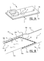
- FIG. 1A shows a flow cell 1.
- Said flow cell 1 comprises a first substantially planar substrate 2, comprising two substrate layers 2A, 2B that are bonded to each other.
- the substrate layers 2A, 2B can be made from any suitable material, for example glass, silicon or ceramic.
- a channel comprising a first channel part 3 and a second channel part 4 is provided, for example by means of etching.
- Said channel is sealed by the second substrate layer 2B that is provided on top of the first substrate layer 2A.
- Said second channel part 4 is in fluid through flow connection with said first channel part 3 and is located downstream of said first channel part 3.
- An inlet reservoir 5 connects to the first channel part 3 for feeding a fluid thereto.
- An outlet reservoir 6 connects to the second channel part 3 for discharging a fluid therefrom.
- Figures 1B and 1C show a transition area T of the first channel part 3 to the second channel part 4.
- Figure 1B shows the transition area T in a downstream view
- figure 1C shows the transition area T in an upstream view.
- each channel part 3, 4 has a bottom 16 and is bounded by opposite sidewalls 17A, 17B.
- These figures further show how an elevated structure 7 provided in the channel divides said channel in said first channel part 3 and said second channel part 4.
- the elevated structure 7 has a height 8 that is smaller than at least a local height 9 of said channel in the area of the elevated structure 7, thereby providing a flow gap between the elevated structure 7 and the second substrate layer 2B provided on top of the channel.
- the height of the flow gap is smaller than the diameter of the beads or particles 14 which are carried along by the fluid in the first channel part 3.
- Said flow gap provides said fluid through flow connection between the first channel part 3 and the second channel part 4 for allowing at least some fluid to flow past said elevated structure 7 into said second channel part 4 while trapping particles to be fed to said first channel part 3 with said fluid in said first channel part 3.
- the elevated structure 7 functions as a weir, defining a horizontal flow gap between its top and the top of the channel (or lower surface of the second substrate layer 2B).
- one otr more vertical flow gaps are defined by the elevated structure. This could be done by forming the elevated structure from a plurality of closely spaced pillars or wall parts extending from the bottom to the top of the channel. In that case the spacing between adjacent pillars or wall parts should be smaller than the diameter of the beads or particles 14.
- the elevated structure has a substantially U-shaped shape having a base 10 and two legs 11 extending from the base in an upstream direction, i.e. in the direction of the inlet reservoir 5.
- the second channel part 4 is locally wider than said first channel part 3 over a length of the channel in the vicinity of, and in particular starting from, the legs 11 up to beyond the base 10 of the elevated structure.
- two outwardly extending perpendicular wall parts 18A, 18B are arranged at the upstream ends of the legs 11, while two converging, inwardly angled wall parts 19A, 19B are formed downstream of the base 10, thus defining two sideflow areas 20A, 20B. This allows fluid to flow through said flow gap provided by the legs 11 into said second channel part 4, i.e.
- the base 10 and the legs 11 together define part of a particle trapping area 12 for trapping particles, as will be described in further detail with respect to figures 3A and 3B .
- Spacer elements in the form of substantially cylindrical pillars 13 are provided on top of the elevated structure 7 for maintaining the second substrate layer in its position spaced apart from said elevated structure 7, thereby maintaining the flow gap.
- Said U-shaped elevated structure provides substantially one continuous U-shaped flow gap, that is only disrupted by said pillars 13.
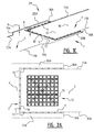
- FIGS 2A and 2B each show an embodiment of the elevated structure 7 according to the invention.
- the legs 11 have a substantially uniform width over the lengths thereof.
- An advantage of this embodiment is that the fluidic resistance of the fluid flowing through the flow gap is substantially uniform over the length of the legs 11.
- the legs 11 have a substantially tapering width in a downstream direction, i.e. the width of the legs reduces in the downstream direction.
- the downstream direction is defined in the direction of the outlet reservoir 6.
- part of said particle trapping area 12 is located in the vicinity of a sensor for providing a sensor area 15.
- the particles trapped in the sensor area 15, and in particular any target molecules captured thereby or coated thereon, may be sensed with use of any suitable sensor.
- the elevated structure is not limited to the embodiments shown in figures 2A and 2B , but may have any suitable substantially U-shaped shape.
- the base 10 may optionally be substantially curved instead of straight, as seen from above.
- the legs 11 may have a substantially tapering width in an upstream direction, i.e. the width of the legs reduces in the upstream direction.
- the legs 11 may have any varying width over the lengths thereof, thereby providing a varying fluidic resistance over the lengths of the legs 11.
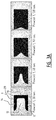
- Figure 3A shows the filling of the particle trapping area 12 of a channel having the elevated structure 7 of figure 2A at time frames of 30 second, 60 seconds, 90 seconds and 120 seconds.
- the particles are denoted by reference numeral 14.
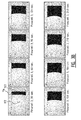
- Figure 3B shows the filling of the particle trapping area of a channel that is not part of the invention.
- the channel of figure 3B has similar dimensions as the channel of figures 2A and 3A .
- the first and second channel parts of figure 3B have substantially the same width as the first channel part of the channel of figures 2A and 2B .
- the channel of figure 2B has a one sided elevated structure 70 that extends orthogonal to the longitudinal direction.
- the particle trapping area 112 is defined by part of the first channel upstream of the elevated structure 70. Filling of the particle trapping area 112 with particles 114 is shown at time frames of 30 second, 60 seconds, 90 seconds, 120 seconds, 150 seconds, 180 seconds, 210 seconds and 240 seconds.
- Figures 3A and 3B show that the speed of filling of the particle trapping area 12 of the channel according to the invention as shown in figure 3A is relatively high with respect to the channel of figure 3B .
- the particle trapping area 12 of the channel according to the invention as shown in figures 2A and 3A is substantially filled after 120 seconds, while the particle trapping area 112 of the channel of figure 3B is not even completely filled after 240 seconds.
- the filling speed of the channel of figure 3B significantly reduces with an increasing number of particles trapped in the particle trapping area 112, due to an increased flow resistance.
- the filling speed of the particle trapping area 12 of the channel according to the invention maintains relatively high. This is a result of the total flow resistance offered by the particles trapped in the particle trapping area 12 and the elevated structure 7 being relatively low.
- Protocol for use of an assembly comprising the flow cell according to the invention and an optical CMOS sensor in sample analysis
- An assembly comprising the flow cell according to the present invention and an optical CMOS sensor can be used for the analysis of fluid samples, such as for instance bodily fluids.
- fluid samples such as for instance bodily fluids.
- the following protocol was used for the measurement of the samples prepared as described in Examples 2-5.
- the beads were blocked with casein, by incubation in 1 % casein PBS Buffer (Thermoscientific, Leuven, Belgium) on a roller at room temperature for 5 min (1 ⁇ l of 10 mg beads/ml in 99 ⁇ l blocking solution per sample). Afterwards, the beads were separated from the blocking solution with the use of an external magnet and 100 ⁇ l of HRP-IgG diluted in 1 % casein PBS Buffer was added to the beads. The HRP-IgG was incubated for 30 min with the beads on a roller at room temperature.
- casein PBS Buffer Thermoscientific, Leuven, Belgium
- the coated beads were blocked with casein just before use, by incubation in 1 % casein PBS Buffer (Thermoscientific, Leuven, Belgium) on a roller at room temperature for 5 min (1 ⁇ l of 10 mg beads/ml in 99 ⁇ l blocking solution per sample).
- a serial dilution of A ⁇ 42 was prepared in 0,1% casein.
- the A ⁇ 42 dilutions were premixed with an amyloid specific detection antibody conjugated with HRP which binds to the a-terminal end amyloid (JRF/AßN/25-HRP) (Department of Neuroscience at Janssen R&D, Belgium).
- the beads were separated from the blocking solution with the use of an external magnet and 100 ⁇ l of the A ⁇ 42-detection antibody mixture was added to the beads and incubated for 30 min on a roller at room temperature. After this incubation, non-bound antibodies were washed away in three wash steps with 200 ⁇ l PBST (PBS + 0.05 % Tween) and one with 50 ⁇ l PBS. For each wash step, beads were separated from the liquid with the use of an external magnet and were dissolved in wash buffer. After the last wash step the detection was performed following the protocol as described in Example 1.
- Figure 5A shows the results of the detection of different concentrations of Aß42 with a chemiluminescent bead ELISA with readout in the assembly comprising the flow cell according to the present invention and an optical CMOS sensor.
- the detection of amyloid beta 42 with assembly shows a LLOD of 1 pg/ml or 200 fM, which is more sensitive than the commercial available colorimetric plate ELISAs for amyloid beta 42 detection (see Figure 5B ).
- IP-10 IFN-gamma-inducible protein 10
- a serial dilution of human IP-10 was prepared in 1 % casein PBS Buffer (Thermoscientific, Leuven, Belgium). After the blocking step, the blocking solution was replaced by the diluted human IP-10 and incubated for 1 h at room temperature. After this incubation, non-bound antibodies were washed away in three wash steps with 200 ⁇ l PBST (PBS + 0.05 % Tween) and one with 100 ⁇ l PBS. After the wash steps, the bound IP-10 were detected with the biotin conjugated detection antibody from the IP-10 Human Antibody Pair kit (Life technologies, Gent, Belgium).
- IP-10 concentration gradient of IP-10 was measured in triplicate (see Figure 6A ).
- the detection of IP-10 with the assembly comprising the flow cell according to the invention and an optical CMOS sensor shows a LLOD of 4 pg/ml or 460 fM, which is in the same range as commercial available colorimetric plate ELISAs and Fluorescent bead based ELISAs (see figure 6B ).
- the readout of antibody assays can be performed with the assembly comprising the flow cell according to the present invention and an optical CMOS sensor.
- a serial dilution of a positive plasma sample was prepared in 1 % casein PBS Buffer (Thermoscientific, Leuven, Belgium).
- the beads were separated from the blocking solution with the use of an external magnet and 100 ⁇ l of the diluted plasma was added to the beads and incubated for 1 h on a roller at room temperature. After this incubation, non-bound antibodies were washed away in three wash steps with 200 ⁇ l PBST (PBS + 0.05 % Tween) and one with 50 ⁇ l PBS.
- PBST PBS + 0.05 % Tween
- HRP-IgG anti-human IgG conjugated with HRP (HRP-IgG) (Ortho Clinical Diagnostics, USA) was used as detection antibody.
- HRP HRP
- This detection antibody was 10 000 times diluted in 1 % casein PBS Buffer (Thermoscientific, Leuven, Belgium). 100 ⁇ l of this diluted detection antibody was incubated with the beads for 30 min on a roller at room temperature. After this last incubation step, non-bound antibodies were washed away in three wash steps with 200 ⁇ l PBST (PBS + 0.05 % Tween) and one with 50 ⁇ l PBS. Afterwards, the detection was performed following the protocol as described in Example 1.
- the amount of JCV VP1 specific antibodies in the same positive plasma sample was determined with a colorimetric plate ELISA as described below.
- HRP-IgG bound was visualized by incubation with 100 ⁇ l TMB substrate per well during 10 min at room temperature. After this 10 min incubation, the reaction was stopped by adding an equal volume of IN HCl per well. The optical density was than measured at 450nm with the SPECTRAmax 384 Plus (Molecular devices, California, United states).
- Figures 7A and 7B show that the sensitivity of the chemiluminescent bead ELISA with readout in the developed assembly comprising the flow cell according to the present invention and an optical CMOS sensor is 7-fold more sensitive as the colorimetric plate-based ELISA.
- the lowest detectable dilution with the chemiluminescent bead ELISA with readout in the developed assembly was 82458 times diluted, compared with 12428 times diluted for the colorimetric plate ELISA.
Landscapes
- Health & Medical Sciences (AREA)
- Chemical & Material Sciences (AREA)
- Immunology (AREA)
- Life Sciences & Earth Sciences (AREA)
- Hematology (AREA)
- Engineering & Computer Science (AREA)
- Analytical Chemistry (AREA)
- General Health & Medical Sciences (AREA)
- Molecular Biology (AREA)
- Biomedical Technology (AREA)
- Urology & Nephrology (AREA)
- Physics & Mathematics (AREA)
- Chemical Kinetics & Catalysis (AREA)
- Clinical Laboratory Science (AREA)
- Dispersion Chemistry (AREA)
- Biotechnology (AREA)
- Microbiology (AREA)
- Food Science & Technology (AREA)
- Medicinal Chemistry (AREA)
- Cell Biology (AREA)
- Biochemistry (AREA)
- General Physics & Mathematics (AREA)
- Pathology (AREA)
- Fluid Mechanics (AREA)
- Apparatus Associated With Microorganisms And Enzymes (AREA)
- Investigating Or Analysing Materials By The Use Of Chemical Reactions (AREA)
Abstract
- a first channel part;
- a second channel part in fluid through flow connection with said first channel part and downstream of said first channel part;
- an elevated structure provided in said channel that divides said channel in said first channel part and said second channel part and for trapping particles in said first channel part;
- at least one flow gap provided by said elevated structure for providing said fluid through flow connection between the first channel part and the second channel part for allowing, in use, at least some fluid to flow past said elevated structure into said second channel part while trapping said particles in said first channel part;
wherein said elevated structure is substantially U-shaped and has a base extending substantially between the opposite sidewalls of the channel and two legs extending from the base in an upstream direction, wherein at least part of said U-shaped elevated structure defines at least part of a particle trapping area for trapping the particles to be fed to said channel.
Description
- The invention relates to a channel for trapping particles to be fed to the channel with a fluid, said channel having a bottom and opposite sidewalls, the sidewalls defining a width of the channel. The invention further relates to a flow cell comprising such a channel. The invention also relates to an assembly comprising such a flow cell and a detection means. The invention also relates to a method for trapping particles in a channel. The invention also relates to a method for analyzing a sample using such an assembly.
- Channels for trapping particles are known per se and may for example be part of a microfluidic detection module or analysis system. Usually, in such systems functionalized micro beads are fed to the channel with a fluid and trapped in a particle trapping area thereof. A sample with target molecules is then fed to said channel, wherein said micro beads are arranged to capture said target molecules from said sample. Alternatively, the beads may be coated with the target molecules prior to feeding the particles to the channel. The particle trapping area is arranged in the vicinity of a sensor, such that the captured target molecules may be sensed thereby.
- Prior art document
US 2010/003666 A1 discloses a method for detection of molecular recognition and analysis of cells. The method makes use of a specific microfluidic system architecture for conducting biomolecular and cell assays. This architecture includes an array of U-shaped weir-traps, which are arranged in a flow chamber which is formed between a substrate and a cover. Each weir-trap is shaped as a rectangular block having a semi-circular recess in its upstream face. Each weir-trap has a height that is less than the distance between the substrate and the cover, so that a reduced fluid flow space is formed, which is smaller than the size of particles entrained in the fluid flow through the device. The weir-traps are arranged in parallel rows perpendicular to the inflow direction, and weir-traps in each row are offset with respect to weir-traps in an adjacent row. The particles in this document are biological agents, e.g. a cell or an analyte. Analysis instrumentation may be associated with each individual weir-trap or with the trapping array as a whole. - Prior art document
US 2014/174933 A1 discloses a droplet actuator comprising a base substrate on which rows of electrodes are arranged for performing droplet operations, e.g. to transport a droplet. Droplets may comprise one or more beads, which may carry targets of interest. In the embodiment offigure 3 of this document a U-shaped barrier is arranged over a row of electrodes to restrain transport of beads in the droplets. The droplets are immersed in a filler fluid with which they do not mix. The filler fluid and droplets are held in a space between a lower substrate carrying the electrodes and an upper substrate associated with a ground electrode 138. The barrier is suspended from the upper substrate and has a height which is smaller than the distance between the upper and lower substrate, thus leaving free a distance through which the droplet may flow. Beads will be restrained by the barrier. Although the beads are said to carry targets of interest, this document does not disclose any detection means. - In prior art document
US 2011/045994 A1 a device and method are disclosed for microscale particle capturing and particle pairing, i.a. for high yield assaying. The device includes a particle patterning device having an array of capture units. The capture units are arranged in rows or columns, with capture units in one row offset from units in an adjacent row. Each capture unit has a first and second chambers or capture cups on opposite sides. The first chamber serves to capture the first particle, which is then transferred to a second chamber of an opposing capture unit by reversal of flow. Then a second particle is captured in the second chamber and the first and second particles bind or react. Due to the presence of chambers on opposite sides each capture unit is H-shaped, rather then U-shaped. The device further includes a light source and a detector mounted opposite the light source for visual detection of the trapped particles. - And finally, prior
art document EP 2 336 781 A1 discloses a cell and a method for testing or analyzing disk-shaped microbeads. These microbeads are covered with a probe substrate that has affinity for a target substrate. The test cell includes a containing space that is closed off by a sealing pillar. The containing space is partitioned by a partition pillar into a supply space having a supply port and a discharge space having a discharge port. The partition pillar is made up of pillar members and spaces or cut outs there between. The microbeads supplied from the supply port are collected or concentrated in a Ω-shaped part of the partition pillar. The containing space is arranged between a support substrate and a transparent cover, and an image detector is provided for analyzing samples. - It is an object of the invention to provide an improved channel for trapping particles. In particular it may be an object of the invention to provide a channel for trapping particles with an increased filling speed.
- This object is achieved by providing a channel according to the preamble, which channel comprises:
- a first channel part;
- a second channel part in fluid through flow connection with said first channel part and downstream of said first channel part;
- an elevated structure provided in said channel that divides said channel in said first channel part and said second channel part and for trapping particles in said first channel part;
- at least one flow gap provided by said elevated structure for providing said fluid through flow connection between the first channel part and the second channel part for allowing, in use, at least some fluid to flow past said elevated structure into said second channel part while trapping said particles in said first channel part;
- Filing of the particle trapping area of said channel with particles occurs by feeding a fluid with particles to said first channel part. The at least one flow gap provided by said elevated structure has at least one of a width or a height that is smaller than a smallest dimension of said particles, such that the particles cannot flow there through and will be trapped in the first channel part in said particle trapping area, while at least some of the fluid will flow through said flow gap past said elevated structure into said second channel part. An advantage of the elevated structure being substantially U-shaped is that the flow resistance offered by the particles trapped in the particle trapping area and the elevated structure is relatively low, such that filling of the particle trapping area may occur relatively fast.
- Such a substantially U-shaped elevated structure extending substantially between the sidewalls of the channel in particular provides the advantage of providing a relatively large flow gap area for passing of liquid and a relatively large area for trapping particles for a relatively small width of the channel. This is because the elevated structure and thereby the at least one flow gap is not only provided over the width of the channel but also over a part of the length of the channel at two longitudinal sides thereof. In particular the base of the U-shaped elevated structure and thereby the at least one flow gap provided by the base extends substantially orthogonal to the longitudinal direction of the channel and thus over the width of the channel, or at least the width of the first channel part. The legs of the U-shaped elevated structure and thereby the at least one flow gap provided by the legs extend substantially parallel to the longitudinal direction of the channel and thus over said part of the length of the channel at the two longitudinal sides thereof.
- The flow gap, or plurality of flow gaps together, hereby also define a substantially U-shaped shape having a base and two legs extending from the base in an upstream direction.
- It is noted that said particles to be fed to said channel may be any suitable particles. For example, said particles may be substantially spherical beads. In such a case the width and height of the flow gap are chosen such that at least one thereof is smaller than the diameter of the beads.
- It is further noted that the fluid to be fed to said channel may be any suitable fluid, either a gas or a liquid. For example, said fluid may be chosen from the group consisting of inert gasses and aqueous solutions.
- Said flow gap may be provided in any suitable way.
- For example said flow gap may comprise a plurality of substantially vertical gaps in the elevated structure.
- In another embodiment of the channel according to the invention said flow gap is provided by at least a part of said elevated structure having a height that is smaller than at least a local height of said channel in the area of the elevated structure.
- This way, the fluid may flow over the elevated structure in the second channel part, while trapping the particles in the first channel part.
- Said part, or parts, of said elevated structure having a height that is smaller than at least a local height of said channel in the area of the elevated structure preferably extends over at least part of the base and at least part of each leg of the U-shaped elevated structure.
- In an embodiment of the channel according to the invention the flow gap defined by said elevated structure having a height that is smaller than at least a local height of said channel in the area of the elevated structure may be provided over substantially the whole length of the U-shaped elevated structure.
- Said flow gap may be substantially one continuous flow gap, optionally disrupted with spacer elements, as described below.
- Said channel may be covered by a cover, for example a substrate. In such an embodiment the local height of said channel is defined between the local bottom of the channel and the local (lower) side of the cover facing the channel.
- Optionally at least one spacer element is provided for spacing said cover from said bottom and/or from said elevated structure, thereby maintaining said gap provided between the elevated structure and the cover. For example, a plurality of spacer elements, each having the form of a cylindrical or beamlike pillar may be provided, that extend between the elevated structure and the cover or between the bottom of the channel and the cover.
- The gap defined by said elevated structure having a height that is smaller than at least a local height of said channel in the area of the elevated structure is chosen to be smaller than the smallest dimension of the particles, thereby preventing the particles from flowing there through. For example, but not limited thereto, said particles may have a smallest dimension of between 2 - 4 µm, while said gap may have a height of less than 2 µm, for example between 1.0 - 1.9 µm. The height of said gap may be constant or vary over the length of the elevated structure.
- In another embodiment of the channel according to the invention said legs have a substantially uniform width over the lengths thereof.
- An advantage of this embodiment is that the fluidic resistance of the fluid flowing through the flow gap is substantially uniform over the length of the legs.
- In another embodiment of the channel according to the invention said legs have a substantially tapering width in a downstream direction.
- An advantage of this embodiment is that the fluidic resistance of the fluid flowing through the flow gap depends on the local width of the legs, wherein an increased width results in a higher fluidic resistance and vice versa.
- If the width of the legs tapers from relatively wide to relatively narrow in said downstream direction of the channel, the fluidic resistance of the flow gap of the legs decreases towards the base of the elevated structure, such that in the beginning of the trapping process, the particles tend to be trapped near the base of the elevated structure. This provides a more even filling of the particles, as filling starts from the base towards the free ends of the legs, and thereby reduces the risk on obtaining unfilled areas closed off by surrounding particles.
- In another embodiment of the channel according to the invention said legs have a length that is between 0.5 to 1 times the length of the particle trapping area.
- The particle trapping area may thus be just as long as the legs of the elevated structure up to twice as long as the legs of the elevated structure, such that the particle trapping area is also defined by part of the longitudinal side walls of the first channel part.
- In another embodiment of the channel according to the invention said second channel part is at least locally wider than said first channel part in the area of the elevated structure.
- Said locally wider second channel part, which may surround the U-shaped elevated structure, allows the fluid to flow through the flow gap under an angle to the main flow direction as defined by the longitudinal axis of the channel. This in turn allows allows the fluid to flow through the flow gap in the second channel part over substantially the whole length of the U-shaped elevated structure.
- In another embodiment of the channel according to the invention said channel has a relatively large width compared to its height.
- Such a channel provides a particle trapping area that has a relatively large surface area compared to its height. This may for example allow a good sensing of captured target molecules.
- For example, but not limited thereto, the channel may be between 300 - 1000 µm wide, and may have a height between 6 - 12 µm.
- In an embodiment of the channel according to the invention the width of the channel may be more than 25 times its height, preferably more than 75 times its height, and most preferably more than 125 times its height.
- In another embodiment of the channel according to the invention said channel is a microfluidic channel.
- In another embodiment of the channel according to the invention said channel has capillary action.
- The invention further relates to a flow cell, said flow cell comprising:
- a channel according to any of the embodiments described above or any combination thereof, and
- an inlet port and an outlet port that are in fluid through flow connection with said channel.
- Said inlet port may be in fluid through flow connection with said first channel part and may be used for feeding said fluid with particles to said first channel part. Said outlet port may be in fluid through flow connection with said second channel part and may be used for discharging said fluid from said second fluid part.
- The invention further relates to an assembly of a flow cell according to any of the above described embodiments or combination thereof and a detection means.
- Said detection means may be used for detecting target molecules of a sample to be analyzed.
- Said detection means may for example comprise a microscope or a sensor. Said sensor may for example be an optical sensor, such as a luminescent, fluorescent, or optical density sensor, or an electronical sensor, such as a conductimetric, amperometric, or potentiometric sensor.
- Said detection means and flow cell may either be connected to each other, either in a fixed manner or releasably, or may not be connected to each other. The assembly of the detection means and flow cell may optionally be provided in a common package, even if they are not connected to each other.
- In a preferred embodiment, the assembly comprises the detection means as an integrated element. The advantage of having the detection means as an integrated element is that the assembly may be used as a point-of-care test without the need for external readout instruments. The assembly can thus be used in a mobile or peripheral setting, such as for instance at the patient's bedside or in resource limited countries with limited access to hospitals and clinical labs.
- The assembly comprising the flow cell according to any of the above described embodiments or combination thereof and a detection means can be used for the analysis of samples. Molecules in such samples can be measured with high sensitivity due to the design of the channel according to the invention. With high sensitivity is meant a sensitivity comparable to or higher than the sensitivity achieved with classical lab-based assays, and a sensitivity higher than the classical point-of-care tests currently used, such as for instance lateral flow tests, dipstick tests, etc.
- The invention further relates to a method for trapping particles in a channel, optionally of a flow cell, said method comprising the steps of:
- (a) providing a said channel according to any of the above described embodiments or combination thereof or a flow cell according to any of the above described embodiments or combination thereof;
- (b) feeding a fluid with particles to be trapped to said first channel part for trapping said particles in said particle trapping area.
- Prior to feeding the particles to the channel in step (b), said particles may be coated with target molecules and/or capture molecules.
- Capture molecules are molecules that bind target molecules through a specific interaction. Target molecules are molecules that are to be measured, and will bind to the capture molecules when these are brought into contact with each other. Capture molecules can thus be used as a means in the measurement of target molecules. Said target molecules may be target molecules of a sample to be analyzed, such as for example peptides or proteins, including but not limited to disease specific biomarkers, antibodies or small molecules in clinical samples, and/or chemical agents in clinical, environmental and/or food samples. Said capture molecules may for example be DNA, peptides and/or proteins, such as for instance antibodies, antigens, receptors, ligands, etc.. Said capture molecules may be arranged to capture target molecules of a sample to be analyzed to allow for their specific interaction with the target molecule,
- In another embodiment of the method according to the invention the particles that are fed to said first channel part in step (b) have a smallest cross sectional size that is larger than said at least one flow gap, thereby preventing said particles from flowing through said flow gap.
- The invention further relates to a method for analyzing a sample, said method comprising the steps of:
- (a) providing an assembly according to any of the above described embodiments or combination thereof;
- (b) feeding a fluid with particles to be trapped to said first channel part for trapping said particles in said particle trapping area, said particles being coated with capture molecules for capturing target molecules from said sample to be analyzed;
- (c) feeding said sample to be analyzed to said first channel part, and
- (d) analyzing said sample by means of said detection means.
- With "analyzing" is meant the detection of the presence of target molecules and the quantity thereof.
- The presence of target molecules, i.e. whether the capture molecules on the particles have bound any target molecules in the sample to be analyzed, can be detected in various ways known to the skilled person. This may, for instance, be achieved by labeling a detection molecule with a fluorescent, chemiluminescent, or radioactive label, and feeding the labelled detection molecule to the particles and sample to be analyzed in said first channel part. This may also be achieved by means of an enzymatic reaction.
- Accordingly, in a preferred embodiment the method comprises the steps of:
- (a) providing an assembly according to any of the above described embodiments or combination thereof;
- (b) feeding a fluid with particles to be trapped to said first channel part for trapping said particles in said particle trapping area, said particles being coated with capture molecules for capturing target molecules from said sample to be analyzed;
- (c) feeding said sample to be analyzed to said first channel part,
- (d) feeding a detection antibody conjugated to an enzyme to said first channel part,
- (e) feeding a substrate which reacts with the enzyme conjugated to the detection antibody to said first channel part; and
- (f) analyzing said sample by means of said detection means.
- The invention further relates to a method for analyzing a sample, said method comprising the steps of:
- (a) providing an assembly according to any of the above described embodiments or combination thereof;
- (b) feeding a fluid with particles to be trapped to said first channel part for trapping said particles in said particle trapping area, said particles being coated with target molecules of a sample to be analyzed;
- (c) analyzing said sample by means of said detection means.
- With "analyzing" is meant the detection of the presence of target molecules and the quantity thereof.
- The presence of target molecules can be detected in various ways known to the skilled person. This may, for instance, be achieved by labeling a detection molecule with a fluorescent, chemiluminescent, or radioactive label, and feeding the labelled detection molecule to the particles coated with the target molecules in said first channel part. This may also be achieved by means of an enzymatic reaction. Accordingly, in a preferred embodiment the method comprises the steps of:
- (a) providing an assembly according to any of the above described embodiments or combination thereof;
- (b) feeding a fluid with particles to be trapped to said first channel part for trapping said particles in said particle trapping area, said particles being coated with target molecules of a sample to be analyzed;
- (c) feeding a detection antibody conjugated to an enzyme to said first channel part,
- (d) feeding a substrate which reacts with the enzyme conjugated to the detection antibody to said first channel part; and
- (e) analyzing said sample by means of said detection means.
- The invention will be further elucidated with reference to figures shown in a drawing:
-
Figure 1A : A schematic perspective view of a part of a flow cell according to an embodiment of the invention. -
Figures 1B and 1C : A detailed view of a particle trapping area of the flow cell offigure 1A . -
Figures 2A and2B : A schematic top view of two embodiments of the elevated structure according to the invention. -
Figures 3A : Photo's showing the filling of the particle trapping area of the embodiment offigure 2A . -
Figure 3B : Photo's showing the filling of the particle trapping area of an elevated structure that is not part of the invention. -
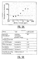
Figure 4A : The normalized luminescence measured on the assembly comprising the flow cell according to the invention and an optical CMOS sensor (Average of n=3) for different concentration of HRP-IgG. The error bar shows the SD of the triplicate measurements and the dotted line shows the threshold value, defined by "The average of the blank + 3 x SD" (n=3). -
Figure 4B : Table showing the performance of readout in the assembly comprising the flow cell according to the invention and an optical CMOS sensor compared with lab based immunoassays. -
Figure 5A : Detection ofamyloid beta 42 by a chemiluminescent bead ELISA with readout in the assembly comprising the flow cell according to the invention and an optical CMOS sensor. The error bar shows the SD of the triplicate measurements and the dotted line shows the threshold value, defined by "The average of the blank + 3 x SD" (n=3). -
Figure 5B : Table showing the performance of chemiluminescent bead ELISA with readout in the assembly comprising the flow cell according to the invention and an optical CMOS sensor compared with commercialavailable Aß 42 lab-based assays, according to LLOD reported by manufacturers. -
Figure 6A : Detection of IP-10 by a chemiluminescent bead ELISA with readout in the assembly comprising the flow cell according to the invention and an optical CMOS sensor. The error bar shows the SD of the triplicate measurements and the dotted line shows the threshold value, defined by "The average of the blank + 3 x SD" (n=3). -
Figure 6B : Table showing the performance of chemiluminescent bead ELISA with readout in the assembly comprising the flow cell according to the invention and an optical CMOS sensor compared with commercial available IP-10 lab-based assays, according to LLOD reported by manufacturers. -
Figure 7A : Detection of anti VP1 antibodies in a diluted positive plasma sample by a chemiluminescent bead ELISA with readout in the assembly comprising the flow cell according to the invention and an optical CMOS sensor. -
Figure 7B : Detection of anti VP1 antibodies in a diluted positive plasma sample by a colorimetric plate ELISA. The error bars show the SD of the triplicate measurements and the dotted line shows the threshold value, defined by "The average of the blank + 3 x SD" (n=3). -
Figure 1A shows aflow cell 1. Saidflow cell 1 comprises a first substantiallyplanar substrate 2, comprising twosubstrate layers first substrate layer 2A of saidfirst substrate 2, a channel comprising afirst channel part 3 and asecond channel part 4 is provided, for example by means of etching. Said channel is sealed by thesecond substrate layer 2B that is provided on top of the first substrate layer 2A. Saidsecond channel part 4 is in fluid through flow connection with saidfirst channel part 3 and is located downstream of saidfirst channel part 3. Aninlet reservoir 5 connects to thefirst channel part 3 for feeding a fluid thereto. Anoutlet reservoir 6 connects to thesecond channel part 3 for discharging a fluid therefrom. -
Figures 1B and 1C show a transition area T of thefirst channel part 3 to thesecond channel part 4.Figure 1B shows the transition area T in a downstream view andfigure 1C shows the transition area T in an upstream view. These figures show that eachchannel part opposite sidewalls elevated structure 7 provided in the channel divides said channel in saidfirst channel part 3 and saidsecond channel part 4. In the illustrated embodiment theelevated structure 7 has aheight 8 that is smaller than at least alocal height 9 of said channel in the area of theelevated structure 7, thereby providing a flow gap between theelevated structure 7 and thesecond substrate layer 2B provided on top of the channel. The height of the flow gap is smaller than the diameter of the beads orparticles 14 which are carried along by the fluid in thefirst channel part 3. Said flow gap provides said fluid through flow connection between thefirst channel part 3 and thesecond channel part 4 for allowing at least some fluid to flow past saidelevated structure 7 into saidsecond channel part 4 while trapping particles to be fed to saidfirst channel part 3 with said fluid in saidfirst channel part 3. - In the illustrated embodiment the
elevated structure 7 functions as a weir, defining a horizontal flow gap between its top and the top of the channel (or lower surface of thesecond substrate layer 2B). However, it is also conceivable that one otr more vertical flow gaps are defined by the elevated structure. This could be done by forming the elevated structure from a plurality of closely spaced pillars or wall parts extending from the bottom to the top of the channel. In that case the spacing between adjacent pillars or wall parts should be smaller than the diameter of the beads orparticles 14. - The elevated structure has a substantially U-shaped shape having a base 10 and two
legs 11 extending from the base in an upstream direction, i.e. in the direction of theinlet reservoir 5. Thesecond channel part 4 is locally wider than saidfirst channel part 3 over a length of the channel in the vicinity of, and in particular starting from, thelegs 11 up to beyond thebase 10 of the elevated structure. In the illustrated embodiment two outwardly extendingperpendicular wall parts legs 11, while two converging, inwardlyangled wall parts 19A, 19B are formed downstream of thebase 10, thus defining twosideflow areas legs 11 into saidsecond channel part 4, i.e. to flow under an angle with respect to the main fluid flow direction as defined by the longitudinal axis of the channel. Thebase 10 and thelegs 11 together define part of aparticle trapping area 12 for trapping particles, as will be described in further detail with respect tofigures 3A and3B . Spacer elements in the form of substantiallycylindrical pillars 13 are provided on top of theelevated structure 7 for maintaining the second substrate layer in its position spaced apart from saidelevated structure 7, thereby maintaining the flow gap. Said U-shaped elevated structure provides substantially one continuous U-shaped flow gap, that is only disrupted by saidpillars 13. -
Figures 2A and2B each show an embodiment of theelevated structure 7 according to the invention. - In
figure 2A thelegs 11 have a substantially uniform width over the lengths thereof. An advantage of this embodiment is that the fluidic resistance of the fluid flowing through the flow gap is substantially uniform over the length of thelegs 11. - In
figure 2B thelegs 11 have a substantially tapering width in a downstream direction, i.e. the width of the legs reduces in the downstream direction. The downstream direction is defined in the direction of theoutlet reservoir 6. An advantage of the tapering width is that the fluidic resistance of the flow gap of thelegs 11 decreases towards thebase 10 of theelevated structure 7, such that in the beginning of the trapping process, theparticles 14 tend to be trapped near thebase 10 of theelevated structure 7. This provides a more even filling of the particles, as filling starts from the base 10 towards the upstream ends of thelegs 11. - As is further shown in
figures 2A and2B , part of saidparticle trapping area 12 is located in the vicinity of a sensor for providing asensor area 15. The particles trapped in thesensor area 15, and in particular any target molecules captured thereby or coated thereon, may be sensed with use of any suitable sensor. - It is noted, that the elevated structure is not limited to the embodiments shown in
figures 2A and2B , but may have any suitable substantially U-shaped shape. - For example, the
base 10 may optionally be substantially curved instead of straight, as seen from above. - For example, the
legs 11 may have a substantially tapering width in an upstream direction, i.e. the width of the legs reduces in the upstream direction. - For example, the
legs 11 may have any varying width over the lengths thereof, thereby providing a varying fluidic resistance over the lengths of thelegs 11. -
Figure 3A shows the filling of theparticle trapping area 12 of a channel having theelevated structure 7 offigure 2A at time frames of 30 second, 60 seconds, 90 seconds and 120 seconds. The particles are denoted byreference numeral 14. -
Figure 3B shows the filling of the particle trapping area of a channel that is not part of the invention. Infigure 3B the same reference numerals are used for denoting the same elements, but increased by 100. The channel offigure 3B has similar dimensions as the channel offigures 2A and3A . In particular the first and second channel parts offigure 3B have substantially the same width as the first channel part of the channel offigures 2A and2B . The channel offigure 2B has a one sided elevated structure 70 that extends orthogonal to the longitudinal direction. Theparticle trapping area 112 is defined by part of the first channel upstream of the elevated structure 70. Filling of theparticle trapping area 112 withparticles 114 is shown at time frames of 30 second, 60 seconds, 90 seconds, 120 seconds, 150 seconds, 180 seconds, 210 seconds and 240 seconds. -
Figures 3A and3B show that the speed of filling of theparticle trapping area 12 of the channel according to the invention as shown infigure 3A is relatively high with respect to the channel offigure 3B . In particular, theparticle trapping area 12 of the channel according to the invention as shown infigures 2A and3A , is substantially filled after 120 seconds, while theparticle trapping area 112 of the channel offigure 3B is not even completely filled after 240 seconds. The filling speed of the channel offigure 3B significantly reduces with an increasing number of particles trapped in theparticle trapping area 112, due to an increased flow resistance. The filling speed of theparticle trapping area 12 of the channel according to the invention maintains relatively high. This is a result of the total flow resistance offered by the particles trapped in theparticle trapping area 12 and theelevated structure 7 being relatively low. - It is noted that the invention is not limited to the shown embodiments but also extends to variants within the scope of the appended claims.
- An assembly comprising the flow cell according to the present invention and an optical CMOS sensor can be used for the analysis of fluid samples, such as for instance bodily fluids. The following protocol was used for the measurement of the samples prepared as described in Examples 2-5.
- For each sample that was tested a different flow cell was used. To prepare the flow cells for detection, the flow cells were first connected with the demonstrator box and calibrated. After the calibration, the dark count (Average of n= 10) was measured and the flow cells were primed from the outlet with PS-atto substrate (Lumigen) by the use of a 2ml syringe.
- The beads with target captured were dissolved in 10µl of PS-atto substrate (Lumigen) and immediately added to the inlet reservoir of the flow cell. By applying vacuum at the outlet, the beads are loaded in the flow cell above the sensor area. After 6 min, the flow was stopped by taking off the vacuum from the outlet. The normalized luminescence at the moment the flow is stopped was used as readout signal. To be able to compare luminescent signals measured at different SPADs (single photon avalanche diodes), the normalized luminescence is calculated with the equation: Normalized Luminescence = (CPS - DC)/DC; With: CPS= The average counts per second of the active SPADs; DC = dark count (average of n =10).
- In this assay, magnetic beads coated with Protein A were used to detect IgG conjugated with HRP (HRP-IgG) (Ortho Clinical Diagnostics, USA). For this assay, 5 mg of Dynabeads M-270 Epoxy (Life technologies, Gent, Belgium) were coated with 50 µg protein A (Thermoscientific, Leuven, Belgium) according to the manufacturer's instructions of the Dynabeads antibody coupling kit (Life technologies, Gent, Belgium). Before using the protein A coated beads for the detection of HRP -IgG, the beads were blocked with casein, by incubation in 1 % casein PBS Buffer (Thermoscientific, Leuven, Belgium) on a roller at room temperature for 5 min (1 µl of 10 mg beads/ml in 99 µl blocking solution per sample). Afterwards, the beads were separated from the blocking solution with the use of an external magnet and 100 µl of HRP-IgG diluted in 1 % casein PBS Buffer was added to the beads. The HRP-IgG was incubated for 30 min with the beads on a roller at room temperature. After this incubation, non-bound IgG were washed away in three wash steps with 200 µl PBST (PBS + 0.05 % Tween) and one wash step with 50 µl PBS. For each wash step, beads were separated from the liquid with the use of an external magnet and were dissolved in wash buffer. After the last wash step the detection was performed following the protocol as described in Example 1.
- The results (see
Figure 4A ) show that the lowest concentration of HRP-IgG that was still detectable with the assembly comprising the flow cell according to the present invention and an optical CMOS sensor is 0,0676 amol HRP-IgG (conjugate) (or 676 aM). This shows that the assembly allows the readout of immunoassays with a higher sensitivity than classical lab based immunoassays (seeFigure 4B ). - To demonstrate that the assembly comprising the flow cell according to the present invention and an optical CMOS sensor can be used for the readout of biological assays, the performance of a peptide assay, more specific Aß42 assay, was tested.
- In this assay, a serial dilution of synthetic Aß42 peptide (Anaspec, USA) was measured. For this assay, 5 mg of Dynabeads M-270 Epoxy (Life technologies, Gent, Belgium) were coated with 50 µg of Aß42 specific antibodies which bind with the c-terminal end of Aß42 (JRF/cAß42/26) (Department of Neuroscience at Janssen R&D, Belgium) according to the manufacturer's instructions of the Dynabeads antibody coupling kit (Life technologies, Gent, Belgium). The coated beads were blocked with casein just before use, by incubation in 1 % casein PBS Buffer (Thermoscientific, Leuven, Belgium) on a roller at room temperature for 5 min (1 µl of 10 mg beads/ml in 99 µl blocking solution per sample). A serial dilution of Aβ42 was prepared in 0,1% casein. The Aβ42 dilutions were premixed with an amyloid specific detection antibody conjugated with HRP which binds to the a-terminal end amyloid (JRF/AßN/25-HRP) (Department of Neuroscience at Janssen R&D, Belgium). After the blocking step, the beads were separated from the blocking solution with the use of an external magnet and 100 µl of the Aβ42-detection antibody mixture was added to the beads and incubated for 30 min on a roller at room temperature. After this incubation, non-bound antibodies were washed away in three wash steps with 200 µl PBST (PBS + 0.05 % Tween) and one with 50 µl PBS. For each wash step, beads were separated from the liquid with the use of an external magnet and were dissolved in wash buffer. After the last wash step the detection was performed following the protocol as described in Example 1.
-
Figure 5A shows the results of the detection of different concentrations of Aß42 with a chemiluminescent bead ELISA with readout in the assembly comprising the flow cell according to the present invention and an optical CMOS sensor. The detection ofamyloid beta 42 with assembly shows a LLOD of 1 pg/ml or 200 fM, which is more sensitive than the commercial available colorimetric plate ELISAs foramyloid beta 42 detection (seeFigure 5B ). - To demonstrate the readout of a protein detection assay, the performance of IP-10 detection with a chemiluminescent bead ELISA with readout in the assembly comprising the flow cell according to the present invention and an optical CMOS sensor was tested.
- In this assay, a serial dilution of recombinant human IP-10 (Life technologies, Gent, Belgium) was measured. For this assay, 5 mg of Dynabeads M-270 Epoxy (Life technologies, Gent, Belgium) were coated with 50 µg of human IP-10 specific capture antibodies from the IP-10 Human Antibody Pair kit (Life technologies, Gent, Belgium) according to the manufacturer's instructions of the Dynabeads antibody coupling kit (Life technologies, Gent, Belgium). The coated beads were blocked with casein just before use, by incubation in 1 % casein PBS Buffer (Thermoscientific, Leuven, Belgium) on a roller at room temperature for 5 min (1 µl of 10 mg beads/ml in 99 µl blocking solution per sample). A serial dilution of human IP-10 was prepared in 1 % casein PBS Buffer (Thermoscientific, Leuven, Belgium). After the blocking step, the blocking solution was replaced by the diluted human IP-10 and incubated for 1 h at room temperature. After this incubation, non-bound antibodies were washed away in three wash steps with 200 µl PBST (PBS + 0.05 % Tween) and one with 100µl PBS. After the wash steps, the bound IP-10 were detected with the biotin conjugated detection antibody from the IP-10 Human Antibody Pair kit (Life technologies, Gent, Belgium). Therefore, 100 µl of 0,2 µg/ml detection antibody (1 000 times diluted in 1 % casein PBS Buffer (Thermoscientific, Leuven, Belgium)) was added to each well and incubated for 1 h at room temperature. After this incubation step, non-bound antibodies were washed away in three wash steps with 200 µl PBST (PBS + 0.05 % Tween) and one with 100 µl PBS. The last incubation step was performed with 100 µl HRP conjugated streptavidin from the IP-10 Human Antibody Pair kit (Life technologies, Gent, Belgium) (600 times diluted in 1 % casein PBS Buffer (Thermoscientific, Leuven, Belgium)) for 1 h at room temperature. After this last incubation step, non-bound antibodies were washed away in three wash steps with 200 µl PBST (PBS + 0.05 % Tween) and one with 50 µl PBS. Afterwards, the detection was performed following the protocol as described in Example 1.
- A concentration gradient of IP-10 was measured in triplicate (see
Figure 6A ). The detection of IP-10 with the assembly comprising the flow cell according to the invention and an optical CMOS sensor shows a LLOD of 4 pg/ml or 460 fM, which is in the same range as commercial available colorimetric plate ELISAs and Fluorescent bead based ELISAs (seefigure 6B ). - In addition to the readout of antigen (peptide/protein) assays also the readout of antibody assays can be performed with the assembly comprising the flow cell according to the present invention and an optical CMOS sensor.
- In this assay, antibodies for JCV VP1 were measured in a serial dilution of a positive plasma sample. For this assay, 5 mg of Dynabeads M-270 Epoxy (Life technologies, Gent, Belgium) were coated with 50 µg of recombinant JCV VP1 (Abcam, Cambridge, UK) according to the manufacturer's instructions of the Dynabeads antibody coupling kit (Life technologies, Gent, Belgium). The coated beads were blocked with casein just before use, by incubation in 1 % casein PBS Buffer (Thermoscientific, Leuven, Belgium) on a roller at room temperature for 5 min (1 µl of 10 mg beads/ml in 99 µl blocking solution per sample). A serial dilution of a positive plasma sample was prepared in 1 % casein PBS Buffer (Thermoscientific, Leuven, Belgium). After the blocking step, the beads were separated from the blocking solution with the use of an external magnet and 100 µl of the diluted plasma was added to the beads and incubated for 1 h on a roller at room temperature. After this incubation, non-bound antibodies were washed away in three wash steps with 200 µl PBST (PBS + 0.05 % Tween) and one with 50 µl PBS. For each wash step, beads were separated from the liquid with the use of an external magnet and were dissolved in wash buffer. To detect the amount of anti-VP1 antibodies bound, an anti-human IgG conjugated with HRP (HRP-IgG) (Ortho Clinical Diagnostics, USA) was used as detection antibody. This detection antibody was 10 000 times diluted in 1 % casein PBS Buffer (Thermoscientific, Leuven, Belgium). 100 µl of this diluted detection antibody was incubated with the beads for 30 min on a roller at room temperature. After this last incubation step, non-bound antibodies were washed away in three wash steps with 200 µl PBST (PBS + 0.05 % Tween) and one with 50 µl PBS. Afterwards, the detection was performed following the protocol as described in Example 1.
- As a comparison, the amount of JCV VP1 specific antibodies in the same positive plasma sample was determined with a colorimetric plate ELISA as described below.
- In this colorimetric plate ELISA, antibodies for JCV VP1 were measured in a serial dilution of the same positive plasma sample used for the chemiluminescent bead ELISA with readout with the assembly comprising the flow cell of the present invention and an optical CMOS sensor. Therefore, the wells of a transparent 96 well maxisorp plate were coated with recombinant JCV VP1 (Abcam, Cambridge, UK) by an overnight incubation at room temperature with 100µl of 1 µg/ml recombinant JCV VP1 dissolved in PBS. After the overnight incubation, the wells were washed with 200 µl PBST (PBS + 0.05 % Tween) and blocked by a one hour incubation at room temperature with 200µl PBS + 1 % BSA. A serial dilution of a positive plasma sample was prepared in 1 % casein PBS Buffer (Thermoscientific, Leuven, Belgium). After the blocking step, the blocking solution was replaced by the diluted plasma sample and incubated for 1 h at room temperature. After this incubation, non-bound antibodies were washed away in three wash steps with 200 µl PBST (PBS + 0.05 % Tween) and the bound antibodies were detected with an anti-human IgG conjugated with HRP (HRP-IgG) (Ortho Clinical Diagnostics, USA). Therefore, 100 µl of detection antibody (1 000 times diluted in 1 % casein PBS Buffer (Thermoscientific, Leuven, Belgium)) was added to each well and incubated 30 min at room temperature. After this last incubation step, non-bound antibodies were washed away in four wash steps with 200 µl PBST (PBS + 0.05 % Tween). Finally, the amount of HRP-IgG bound was visualized by incubation with 100 µl TMB substrate per well during 10 min at room temperature. After this 10 min incubation, the reaction was stopped by adding an equal volume of IN HCl per well. The optical density was than measured at 450nm with the SPECTRAmax 384 Plus (Molecular devices, California, United states).
- The results in
Figures 7A and 7B show that the sensitivity of the chemiluminescent bead ELISA with readout in the developed assembly comprising the flow cell according to the present invention and an optical CMOS sensor is 7-fold more sensitive as the colorimetric plate-based ELISA. The lowest detectable dilution with the chemiluminescent bead ELISA with readout in the developed assembly was 82458 times diluted, compared with 12428 times diluted for the colorimetric plate ELISA.
Claims (16)
- Channel for trapping particles to be fed to said channel with a fluid, said channel having a bottom and opposite sidewalls, the sidewalls defining a width of the channel, said channel further comprising:- a first channel part;- a second channel part in fluid through flow connection with said first channel part and downstream of said first channel part;- an elevated structure provided in said channel that divides said channel in said first channel part and said second channel part and for trapping particles in said first channel part;- at least one flow gap provided by said elevated structure for providing said fluid through flow connection between the first channel part and the second channel part for allowing, in use, at least some fluid to flow past said elevated structure into said second channel part while trapping said particles in said first channel part;wherein said elevated structure is substantially U-shaped and has a base extending substantially between the opposite sidewalls of the channel and two legs extending from the base in an upstream direction, wherein at least part of said U-shaped elevated structure defines at least part of a particle trapping area for trapping the particles to be fed to said channel.
- Channel according to claim 1, wherein at least a part of said elevated structure has a height that is smaller than at least a local height of said channel in the area of the elevated structure, thereby providing said at least one flow gap.
- Channel according to claim 1 or 2, wherein said legs have a substantially uniform width over the lengths thereof.
- Channel according to claim 1 or 2, wherein said legs have a substantially tapering width in a downstream direction.
- Channel according to any of the preceding claims, wherein said legs have a length that is between 0.5 to 1 times the length of the particle trapping area.
- Channel according to any of the preceding claims, wherein said second channel part is at least locally wider than said first channel part in the area of the elevated structure.
- Channel according to any of the preceding claims, wherein said channel has a relatively large width compared to its height, the width of the channel being more than 25 times its height, preferably more than 75 times its height, and most preferably more than 125 times its height.
- Channel according to any of the preceding claims, wherein said channel is a microfluidic channel.
- Channel according to any of the preceding claims, wherein said channel has capillary action.
- Flow cell, said flow cell comprising:- a channel according to any of the preceding claims, and- an inlet port and an outlet port that are in fluid through flow connection with said channel.
- Assembly of a flow cell according to claim 10 and a detection means.
- Method for trapping particles in a channel, optionally of a flow cell, said method comprising the steps of:(a) providing a said channel according to any of the claims 1 - 9 or a flow cell according to claim 10;(b) feeding a fluid with particles to be trapped to said first channel part for trapping said particles in said particle trapping area.
- Method according to claim 12, wherein said particles are coated with target molecules or capture molecules.
- Method according to claim 12 or 13, wherein the particles fed to said first channel part in step (b) have a minimum cross sectional size that is larger than said at least one flow gap.
- Method for analyzing a sample, said method comprising the steps of:(a) providing an assembly according to claim 11;(b) feeding a fluid with particles to be trapped to said first channel part for trapping said particles in said particle trapping area, said particles being coated with capture molecules for capturing target molecules from said sample to be analyzed;(c) feeding said sample to be analyzed to said first channel part, and(d) feeding detection antibody conjugated with an enzyme to said first channel part, and(e) analyzing said sample by means of said detection means.
- Method for analyzing a sample, said method comprising the steps of:(a) providing an assembly according to claim 11;(b) feeding a fluid with particles to be trapped to said first channel part for trapping said particles in said particle trapping area, said particles being coated with target molecules of a sample to be analyzed;(c) feeding detection antibody conjugated with an enzyme to said first channel part, and(d) analyzing said sample by means of said detection means.
Applications Claiming Priority (1)
| Application Number | Priority Date | Filing Date | Title |
|---|---|---|---|
| NL2015287A NL2015287B1 (en) | 2015-08-10 | 2015-08-10 | Channel for trapping particles to be fed to said channel with a fluid. |
Publications (2)
| Publication Number | Publication Date |
|---|---|
| EP3130401A1 true EP3130401A1 (en) | 2017-02-15 |
| EP3130401B1 EP3130401B1 (en) | 2018-11-07 |
Family
ID=55178231
Family Applications (1)
| Application Number | Title | Priority Date | Filing Date |
|---|---|---|---|
| EP16183611.9A Not-in-force EP3130401B1 (en) | 2015-08-10 | 2016-08-10 | Channel for trapping particles to be fed to said channel with a fluid |
Country Status (3)
| Country | Link |
|---|---|
| US (1) | US10254280B2 (en) |
| EP (1) | EP3130401B1 (en) |
| NL (1) | NL2015287B1 (en) |
Cited By (3)
| Publication number | Priority date | Publication date | Assignee | Title |
|---|---|---|---|---|
| WO2018183896A1 (en) * | 2017-03-31 | 2018-10-04 | Forward Biotech, Inc. | Device for measuring fluid volumes |
| US12092650B2 (en) | 2021-12-09 | 2024-09-17 | Forward Biotech, Inc. | Liquid evaluation device |
| US12220699B2 (en) | 2019-01-21 | 2025-02-11 | Forward Biotech, Inc. | Liquid evaluation |
Families Citing this family (29)
| Publication number | Priority date | Publication date | Assignee | Title |
|---|---|---|---|---|
| RU2018107453A (en) | 2015-08-10 | 2019-09-12 | Эссенликс Корп. | DEVICES FOR ANALYSIS AND METHODS IN BIOLOGY / CHEMISTRY, PROVIDING SIMPLIFIED STAGES, SAMPLES OF SMALL VOLUME, INCREASED SPEED AND EASE OF APPLICATION |
| MY194887A (en) | 2015-09-14 | 2022-12-21 | Essenlix Corp | Device and System for Analyzing a Sample, Particularly Blood, as Well as Methods of Using The Same |
| KR101982330B1 (en) | 2015-09-14 | 2019-05-24 | 에센릭스 코프. | Apparatus and systems for collecting and analyzing vapor condensate, in particular condensate, and methods of using the apparatus and system |
| CA3048002A1 (en) | 2016-12-21 | 2018-06-28 | Essenlix Corporation | Devices and methods for authenticating a sample and use of the same |
| JP7003158B2 (en) | 2017-02-07 | 2022-01-20 | エッセンリックス コーポレーション | Compressed open flow assay and use |
| CA3053005A1 (en) | 2017-02-08 | 2018-08-16 | Essenlix Corporation | Sample collection and handling for delayed analysis |
| US11927560B2 (en) | 2017-02-08 | 2024-03-12 | Essenlix Corporation | Bio/chemical material extraction and assay |
| CA3052809A1 (en) | 2017-02-08 | 2018-08-23 | Essenlix Corporation | Qmax assays and applications |
| CN120685901A (en) | 2017-02-08 | 2025-09-23 | 上海宜晟生物科技有限公司 | Digital measurement |
| WO2018148764A1 (en) | 2017-02-08 | 2018-08-16 | Essenlix Corporation | Molecular manipulation and assay with controlled temperature |
| CN110998325B (en) | 2017-02-09 | 2024-08-16 | 上海宜晟生物科技有限公司 | Amplification assay |
| CN110770572B (en) | 2017-02-09 | 2023-08-18 | Essenlix公司 | Colorimetric assay |
| WO2018148607A1 (en) | 2017-02-09 | 2018-08-16 | Essenlix Corporation | Assay using different spacing heights |
| CA3053295A1 (en) | 2017-02-15 | 2018-08-23 | Essenlix Corporation | Assay with rapid temperature change |
| JP7107953B2 (en) | 2017-02-16 | 2022-07-27 | エッセンリックス コーポレーション | Assays using textured surfaces |
| WO2018231877A1 (en) | 2017-06-12 | 2018-12-20 | Essenlix Corporation | Homogeneous assay |
| WO2019028133A1 (en) | 2017-08-01 | 2019-02-07 | Essenlix Corporation | Devices and methods for examining drug effects on microorganisms |
| US11243201B2 (en) | 2017-08-01 | 2022-02-08 | Essenlix Corporation | Sample collection, holding and assaying |
| US11280706B2 (en) | 2017-08-01 | 2022-03-22 | Essenlix Corporation | Dilution calibration |
| US12403465B2 (en) | 2017-10-11 | 2025-09-02 | Essenlix Corporation | Containing a liquid sample |
| US11393561B2 (en) | 2017-10-13 | 2022-07-19 | Essenlix Corporation | Devices and methods for authenticating a medical test and use of the same |
| US11609224B2 (en) | 2017-10-26 | 2023-03-21 | Essenlix Corporation | Devices and methods for white blood cell analyses |
| US10807095B2 (en) | 2017-10-26 | 2020-10-20 | Essenlix Corporation | Making and tracking assay card |
| US11237113B2 (en) | 2017-10-26 | 2022-02-01 | Essenlix Corporation | Rapid pH measurement |
| US11648551B2 (en) | 2017-12-12 | 2023-05-16 | Essenlix Corporation | Sample manipulation and assay with rapid temperature change |
| US11510608B2 (en) | 2017-12-14 | 2022-11-29 | Essenlix Corporation | Devices, systems, and methods for monitoring hair |
| US11156606B2 (en) | 2018-01-11 | 2021-10-26 | Essenlix Corporation | Homogeneous assay (II) |
| US11885952B2 (en) | 2018-07-30 | 2024-01-30 | Essenlix Corporation | Optics, device, and system for assaying and imaging |
| WO2022225597A1 (en) | 2021-04-23 | 2022-10-27 | Becton, Dickinson And Company | Fluid management system for an analyzer and/or sorter type flow type particle analyzer |
Citations (4)
| Publication number | Priority date | Publication date | Assignee | Title |
|---|---|---|---|---|
| US20100003666A1 (en) | 2005-08-19 | 2010-01-07 | The Regents Of The University Of California | Microfluidic Methods for Diagnostics and Cellular Analysis |
| US20110045994A1 (en) | 2008-02-11 | 2011-02-24 | Joel Voldman | Particle capture devices and methods of use thereof |
| EP2336781A1 (en) | 2009-12-16 | 2011-06-22 | Sony Corporation | Cell for testing microbeads and method of analyzing microbeads |
| US20140174933A1 (en) | 2007-08-24 | 2014-06-26 | Advanced Liquid Logic, Inc. | Bead Manipulations on a Droplet Actuator |
Family Cites Families (2)
| Publication number | Priority date | Publication date | Assignee | Title |
|---|---|---|---|---|
| WO2012162779A1 (en) * | 2011-05-27 | 2012-12-06 | The University Of British Columbia | Microfluidic cell trap and assay apparatus for high-throughput analysis |
| EP2914379A1 (en) * | 2012-11-01 | 2015-09-09 | The Charles Stark Draper Laboratory, Inc. | Ex vivo microfluidic analysis of biologic samples |
-
2015
- 2015-08-10 NL NL2015287A patent/NL2015287B1/en not_active IP Right Cessation
-
2016
- 2016-08-10 US US15/233,427 patent/US10254280B2/en active Active
- 2016-08-10 EP EP16183611.9A patent/EP3130401B1/en not_active Not-in-force
Patent Citations (4)
| Publication number | Priority date | Publication date | Assignee | Title |
|---|---|---|---|---|
| US20100003666A1 (en) | 2005-08-19 | 2010-01-07 | The Regents Of The University Of California | Microfluidic Methods for Diagnostics and Cellular Analysis |
| US20140174933A1 (en) | 2007-08-24 | 2014-06-26 | Advanced Liquid Logic, Inc. | Bead Manipulations on a Droplet Actuator |
| US20110045994A1 (en) | 2008-02-11 | 2011-02-24 | Joel Voldman | Particle capture devices and methods of use thereof |
| EP2336781A1 (en) | 2009-12-16 | 2011-06-22 | Sony Corporation | Cell for testing microbeads and method of analyzing microbeads |
Cited By (5)
| Publication number | Priority date | Publication date | Assignee | Title |
|---|---|---|---|---|
| WO2018183896A1 (en) * | 2017-03-31 | 2018-10-04 | Forward Biotech, Inc. | Device for measuring fluid volumes |
| CN110612160A (en) * | 2017-03-31 | 2019-12-24 | 前进生物技术股份有限公司 | Devices for measuring the volume of fluids |
| US11602751B2 (en) | 2017-03-31 | 2023-03-14 | Forward Biotech, Inc. | Liquid evaluation |
| US12220699B2 (en) | 2019-01-21 | 2025-02-11 | Forward Biotech, Inc. | Liquid evaluation |
| US12092650B2 (en) | 2021-12-09 | 2024-09-17 | Forward Biotech, Inc. | Liquid evaluation device |
Also Published As
| Publication number | Publication date |
|---|---|
| US20170045504A1 (en) | 2017-02-16 |
| NL2015287B1 (en) | 2017-02-28 |
| US10254280B2 (en) | 2019-04-09 |
| EP3130401B1 (en) | 2018-11-07 |
Similar Documents
| Publication | Publication Date | Title |
|---|---|---|
| EP3130401B1 (en) | Channel for trapping particles to be fed to said channel with a fluid | |
| AU2020201874B2 (en) | Immunoassay utilizing trapping conjugate | |
| JP6033602B2 (en) | Biomolecule detection method, biomolecule detection apparatus, and analytical device | |
| US20130260481A1 (en) | Analysis device and analysis method | |
| US20120178186A1 (en) | Binding assay with multiple magnetically labelled tracer binding agents | |
| US20130065324A1 (en) | Immunoassay apparatus incorporating microfluidic channel | |
| US10191037B2 (en) | Methods of and systems for improved detection sensitivity of assays | |
| CN101027558A (en) | Method of determining the presence and/or concentration of substances of interest in fluids | |
| KR101993305B1 (en) | Micro chip for analyzing fluids | |
| US20170336404A1 (en) | Rapid immunoassays | |
| ES2536741T3 (en) | Particle Based Bonding Test | |
| US20240091771A1 (en) | Assay device and assay method | |
| KR101786574B1 (en) | Immunodiagnostic cartridge | |
| KR102802234B1 (en) | Method for detecting particles of a target substance contained in a small amount in a fluid sample using microwell particles | |
| US20170176472A1 (en) | Systems and methods for point-of-care hdl and ldl particle assay | |
| CN105705948B (en) | Apparatus and methods for bioanalysis | |
| TWM537659U (en) | Test strip device for rapid detection | |
| KR102015360B1 (en) | Signal amplification kit and manufacturing method thereof in Lateral flow immunoassay | |
| Ohashi et al. | One-step micro-ELISA for highly sensitive determination of TSH | |
| JP2009121861A (en) | Sensor chip and target substance detection method using it | |
| WO2012032891A1 (en) | Measurement apparatus and measurement method both utilizing biological substance detection element |
Legal Events
| Date | Code | Title | Description |
|---|---|---|---|
| PUAI | Public reference made under article 153(3) epc to a published international application that has entered the european phase |
Free format text: ORIGINAL CODE: 0009012 |
|
| STAA | Information on the status of an ep patent application or granted ep patent |
Free format text: STATUS: THE APPLICATION HAS BEEN PUBLISHED |
|
| AK | Designated contracting states |
Kind code of ref document: A1 Designated state(s): AL AT BE BG CH CY CZ DE DK EE ES FI FR GB GR HR HU IE IS IT LI LT LU LV MC MK MT NL NO PL PT RO RS SE SI SK SM TR |
|
| AX | Request for extension of the european patent |
Extension state: BA ME |
|
| STAA | Information on the status of an ep patent application or granted ep patent |
Free format text: STATUS: REQUEST FOR EXAMINATION WAS MADE |
|
| 17P | Request for examination filed |
Effective date: 20170814 |
|
| RBV | Designated contracting states (corrected) |
Designated state(s): AL AT BE BG CH CY CZ DE DK EE ES FI FR GB GR HR HU IE IS IT LI LT LU LV MC MK MT NL NO PL PT RO RS SE SI SK SM TR |
|
| REG | Reference to a national code |
Ref country code: DE Ref legal event code: R079 Ref document number: 602016006935 Country of ref document: DE Free format text: PREVIOUS MAIN CLASS: B01L0003000000 Ipc: G01N0033543000 |
|
| GRAP | Despatch of communication of intention to grant a patent |
Free format text: ORIGINAL CODE: EPIDOSNIGR1 |
|
| STAA | Information on the status of an ep patent application or granted ep patent |
Free format text: STATUS: GRANT OF PATENT IS INTENDED |
|
| RIC1 | Information provided on ipc code assigned before grant |
Ipc: B01L 3/00 20060101ALI20180426BHEP Ipc: G01N 33/543 20060101AFI20180426BHEP |
|
| INTG | Intention to grant announced |
Effective date: 20180524 |
|
| GRAS | Grant fee paid |
Free format text: ORIGINAL CODE: EPIDOSNIGR3 |
|
| GRAA | (expected) grant |
Free format text: ORIGINAL CODE: 0009210 |
|
| STAA | Information on the status of an ep patent application or granted ep patent |
Free format text: STATUS: THE PATENT HAS BEEN GRANTED |
|
| AK | Designated contracting states |
Kind code of ref document: B1 Designated state(s): AL AT BE BG CH CY CZ DE DK EE ES FI FR GB GR HR HU IE IS IT LI LT LU LV MC MK MT NL NO PL PT RO RS SE SI SK SM TR |
|
| REG | Reference to a national code |
Ref country code: GB Ref legal event code: FG4D |
|
| REG | Reference to a national code |
Ref country code: CH Ref legal event code: EP Ref country code: AT Ref legal event code: REF Ref document number: 1062696 Country of ref document: AT Kind code of ref document: T Effective date: 20181115 |
|
| REG | Reference to a national code |
Ref country code: DE Ref legal event code: R096 Ref document number: 602016006935 Country of ref document: DE |
|
| REG | Reference to a national code |
Ref country code: IE Ref legal event code: FG4D |
|
| RAP2 | Party data changed (patent owner data changed or rights of a patent transferred) |
Owner name: JANSSEN PHARMACEUTICA, N.V. Owner name: MICRONIT MICROTECHNOLOGIES B.V. Owner name: NXP B.V. |
|
| REG | Reference to a national code |
Ref country code: NL Ref legal event code: MP Effective date: 20181107 |
|
| REG | Reference to a national code |
Ref country code: LT Ref legal event code: MG4D |
|
| REG | Reference to a national code |
Ref country code: AT Ref legal event code: MK05 Ref document number: 1062696 Country of ref document: AT Kind code of ref document: T Effective date: 20181107 |
|
| PG25 | Lapsed in a contracting state [announced via postgrant information from national office to epo] |
Ref country code: IS Free format text: LAPSE BECAUSE OF FAILURE TO SUBMIT A TRANSLATION OF THE DESCRIPTION OR TO PAY THE FEE WITHIN THE PRESCRIBED TIME-LIMIT Effective date: 20190307 Ref country code: BG Free format text: LAPSE BECAUSE OF FAILURE TO SUBMIT A TRANSLATION OF THE DESCRIPTION OR TO PAY THE FEE WITHIN THE PRESCRIBED TIME-LIMIT Effective date: 20190207 Ref country code: NO Free format text: LAPSE BECAUSE OF FAILURE TO SUBMIT A TRANSLATION OF THE DESCRIPTION OR TO PAY THE FEE WITHIN THE PRESCRIBED TIME-LIMIT Effective date: 20190207 Ref country code: ES Free format text: LAPSE BECAUSE OF FAILURE TO SUBMIT A TRANSLATION OF THE DESCRIPTION OR TO PAY THE FEE WITHIN THE PRESCRIBED TIME-LIMIT Effective date: 20181107 Ref country code: LT Free format text: LAPSE BECAUSE OF FAILURE TO SUBMIT A TRANSLATION OF THE DESCRIPTION OR TO PAY THE FEE WITHIN THE PRESCRIBED TIME-LIMIT Effective date: 20181107 Ref country code: LV Free format text: LAPSE BECAUSE OF FAILURE TO SUBMIT A TRANSLATION OF THE DESCRIPTION OR TO PAY THE FEE WITHIN THE PRESCRIBED TIME-LIMIT Effective date: 20181107 Ref country code: AT Free format text: LAPSE BECAUSE OF FAILURE TO SUBMIT A TRANSLATION OF THE DESCRIPTION OR TO PAY THE FEE WITHIN THE PRESCRIBED TIME-LIMIT Effective date: 20181107 Ref country code: HR Free format text: LAPSE BECAUSE OF FAILURE TO SUBMIT A TRANSLATION OF THE DESCRIPTION OR TO PAY THE FEE WITHIN THE PRESCRIBED TIME-LIMIT Effective date: 20181107 Ref country code: FI Free format text: LAPSE BECAUSE OF FAILURE TO SUBMIT A TRANSLATION OF THE DESCRIPTION OR TO PAY THE FEE WITHIN THE PRESCRIBED TIME-LIMIT Effective date: 20181107 |
|
| PG25 | Lapsed in a contracting state [announced via postgrant information from national office to epo] |
Ref country code: PT Free format text: LAPSE BECAUSE OF FAILURE TO SUBMIT A TRANSLATION OF THE DESCRIPTION OR TO PAY THE FEE WITHIN THE PRESCRIBED TIME-LIMIT Effective date: 20190307 Ref country code: SE Free format text: LAPSE BECAUSE OF FAILURE TO SUBMIT A TRANSLATION OF THE DESCRIPTION OR TO PAY THE FEE WITHIN THE PRESCRIBED TIME-LIMIT Effective date: 20181107 Ref country code: AL Free format text: LAPSE BECAUSE OF FAILURE TO SUBMIT A TRANSLATION OF THE DESCRIPTION OR TO PAY THE FEE WITHIN THE PRESCRIBED TIME-LIMIT Effective date: 20181107 Ref country code: GR Free format text: LAPSE BECAUSE OF FAILURE TO SUBMIT A TRANSLATION OF THE DESCRIPTION OR TO PAY THE FEE WITHIN THE PRESCRIBED TIME-LIMIT Effective date: 20190208 Ref country code: RS Free format text: LAPSE BECAUSE OF FAILURE TO SUBMIT A TRANSLATION OF THE DESCRIPTION OR TO PAY THE FEE WITHIN THE PRESCRIBED TIME-LIMIT Effective date: 20181107 Ref country code: NL Free format text: LAPSE BECAUSE OF FAILURE TO SUBMIT A TRANSLATION OF THE DESCRIPTION OR TO PAY THE FEE WITHIN THE PRESCRIBED TIME-LIMIT Effective date: 20181107 |
|
| PG25 | Lapsed in a contracting state [announced via postgrant information from national office to epo] |
Ref country code: IT Free format text: LAPSE BECAUSE OF FAILURE TO SUBMIT A TRANSLATION OF THE DESCRIPTION OR TO PAY THE FEE WITHIN THE PRESCRIBED TIME-LIMIT Effective date: 20181107 Ref country code: DK Free format text: LAPSE BECAUSE OF FAILURE TO SUBMIT A TRANSLATION OF THE DESCRIPTION OR TO PAY THE FEE WITHIN THE PRESCRIBED TIME-LIMIT Effective date: 20181107 Ref country code: PL Free format text: LAPSE BECAUSE OF FAILURE TO SUBMIT A TRANSLATION OF THE DESCRIPTION OR TO PAY THE FEE WITHIN THE PRESCRIBED TIME-LIMIT Effective date: 20181107 Ref country code: CZ Free format text: LAPSE BECAUSE OF FAILURE TO SUBMIT A TRANSLATION OF THE DESCRIPTION OR TO PAY THE FEE WITHIN THE PRESCRIBED TIME-LIMIT Effective date: 20181107 |
|
| REG | Reference to a national code |
Ref country code: DE Ref legal event code: R097 Ref document number: 602016006935 Country of ref document: DE |
|
| PG25 | Lapsed in a contracting state [announced via postgrant information from national office to epo] |
Ref country code: EE Free format text: LAPSE BECAUSE OF FAILURE TO SUBMIT A TRANSLATION OF THE DESCRIPTION OR TO PAY THE FEE WITHIN THE PRESCRIBED TIME-LIMIT Effective date: 20181107 Ref country code: RO Free format text: LAPSE BECAUSE OF FAILURE TO SUBMIT A TRANSLATION OF THE DESCRIPTION OR TO PAY THE FEE WITHIN THE PRESCRIBED TIME-LIMIT Effective date: 20181107 Ref country code: SK Free format text: LAPSE BECAUSE OF FAILURE TO SUBMIT A TRANSLATION OF THE DESCRIPTION OR TO PAY THE FEE WITHIN THE PRESCRIBED TIME-LIMIT Effective date: 20181107 Ref country code: SM Free format text: LAPSE BECAUSE OF FAILURE TO SUBMIT A TRANSLATION OF THE DESCRIPTION OR TO PAY THE FEE WITHIN THE PRESCRIBED TIME-LIMIT Effective date: 20181107 |
|
| PLBE | No opposition filed within time limit |
Free format text: ORIGINAL CODE: 0009261 |
|
| STAA | Information on the status of an ep patent application or granted ep patent |
Free format text: STATUS: NO OPPOSITION FILED WITHIN TIME LIMIT |
|
| 26N | No opposition filed |
Effective date: 20190808 |
|
| PG25 | Lapsed in a contracting state [announced via postgrant information from national office to epo] |
Ref country code: SI Free format text: LAPSE BECAUSE OF FAILURE TO SUBMIT A TRANSLATION OF THE DESCRIPTION OR TO PAY THE FEE WITHIN THE PRESCRIBED TIME-LIMIT Effective date: 20181107 |
|
| PG25 | Lapsed in a contracting state [announced via postgrant information from national office to epo] |
Ref country code: TR Free format text: LAPSE BECAUSE OF FAILURE TO SUBMIT A TRANSLATION OF THE DESCRIPTION OR TO PAY THE FEE WITHIN THE PRESCRIBED TIME-LIMIT Effective date: 20181107 |
|
| PG25 | Lapsed in a contracting state [announced via postgrant information from national office to epo] |
Ref country code: LU Free format text: LAPSE BECAUSE OF NON-PAYMENT OF DUE FEES Effective date: 20190810 Ref country code: MC Free format text: LAPSE BECAUSE OF FAILURE TO SUBMIT A TRANSLATION OF THE DESCRIPTION OR TO PAY THE FEE WITHIN THE PRESCRIBED TIME-LIMIT Effective date: 20181107 Ref country code: CH Free format text: LAPSE BECAUSE OF NON-PAYMENT OF DUE FEES Effective date: 20190831 Ref country code: LI Free format text: LAPSE BECAUSE OF NON-PAYMENT OF DUE FEES Effective date: 20190831 |
|
| REG | Reference to a national code |
Ref country code: BE Ref legal event code: MM Effective date: 20190831 |
|
| PG25 | Lapsed in a contracting state [announced via postgrant information from national office to epo] |
Ref country code: IE Free format text: LAPSE BECAUSE OF NON-PAYMENT OF DUE FEES Effective date: 20190810 |
|
| PG25 | Lapsed in a contracting state [announced via postgrant information from national office to epo] |
Ref country code: BE Free format text: LAPSE BECAUSE OF NON-PAYMENT OF DUE FEES Effective date: 20190831 |
|
| PG25 | Lapsed in a contracting state [announced via postgrant information from national office to epo] |
Ref country code: CY Free format text: LAPSE BECAUSE OF FAILURE TO SUBMIT A TRANSLATION OF THE DESCRIPTION OR TO PAY THE FEE WITHIN THE PRESCRIBED TIME-LIMIT Effective date: 20181107 |
|
| PG25 | Lapsed in a contracting state [announced via postgrant information from national office to epo] |
Ref country code: HU Free format text: LAPSE BECAUSE OF FAILURE TO SUBMIT A TRANSLATION OF THE DESCRIPTION OR TO PAY THE FEE WITHIN THE PRESCRIBED TIME-LIMIT; INVALID AB INITIO Effective date: 20160810 Ref country code: MT Free format text: LAPSE BECAUSE OF FAILURE TO SUBMIT A TRANSLATION OF THE DESCRIPTION OR TO PAY THE FEE WITHIN THE PRESCRIBED TIME-LIMIT Effective date: 20181107 |
|
| PG25 | Lapsed in a contracting state [announced via postgrant information from national office to epo] |
Ref country code: MK Free format text: LAPSE BECAUSE OF FAILURE TO SUBMIT A TRANSLATION OF THE DESCRIPTION OR TO PAY THE FEE WITHIN THE PRESCRIBED TIME-LIMIT Effective date: 20181107 |
|
| PGFP | Annual fee paid to national office [announced via postgrant information from national office to epo] |
Ref country code: GB Payment date: 20220927 Year of fee payment: 7 |
|
| PGFP | Annual fee paid to national office [announced via postgrant information from national office to epo] |
Ref country code: FR Payment date: 20220926 Year of fee payment: 7 |
|
| GBPC | Gb: european patent ceased through non-payment of renewal fee |
Effective date: 20230810 |
|
| PG25 | Lapsed in a contracting state [announced via postgrant information from national office to epo] |
Ref country code: GB Free format text: LAPSE BECAUSE OF NON-PAYMENT OF DUE FEES Effective date: 20230810 |
|
| PG25 | Lapsed in a contracting state [announced via postgrant information from national office to epo] |
Ref country code: GB Free format text: LAPSE BECAUSE OF NON-PAYMENT OF DUE FEES Effective date: 20230810 Ref country code: FR Free format text: LAPSE BECAUSE OF NON-PAYMENT OF DUE FEES Effective date: 20230831 |
|
| PGFP | Annual fee paid to national office [announced via postgrant information from national office to epo] |
Ref country code: DE Payment date: 20240828 Year of fee payment: 9 |
|
| REG | Reference to a national code |
Ref country code: DE Ref legal event code: R119 Ref document number: 602016006935 Country of ref document: DE |