EP3130304A1 - Treatment tool and surgical system - Google Patents
Treatment tool and surgical system Download PDFInfo
- Publication number
- EP3130304A1 EP3130304A1 EP15776442.4A EP15776442A EP3130304A1 EP 3130304 A1 EP3130304 A1 EP 3130304A1 EP 15776442 A EP15776442 A EP 15776442A EP 3130304 A1 EP3130304 A1 EP 3130304A1
- Authority
- EP
- European Patent Office
- Prior art keywords
- joint
- main unit
- end effector
- treatment device
- shaft member
- Prior art date
- Legal status (The legal status is an assumption and is not a legal conclusion. Google has not performed a legal analysis and makes no representation as to the accuracy of the status listed.)
- Withdrawn
Links
- 238000005096 rolling process Methods 0.000 claims abstract description 70
- 239000012636 effector Substances 0.000 claims abstract description 57
- 230000005540 biological transmission Effects 0.000 claims abstract description 46
- 230000002093 peripheral effect Effects 0.000 claims description 19
- 238000002347 injection Methods 0.000 claims description 5
- 239000007924 injection Substances 0.000 claims description 5
- 239000013013 elastic material Substances 0.000 claims description 3
- 230000004043 responsiveness Effects 0.000 description 9
- 230000033001 locomotion Effects 0.000 description 8
- 238000003780 insertion Methods 0.000 description 7
- 230000037431 insertion Effects 0.000 description 7
- 230000004048 modification Effects 0.000 description 7
- 238000012986 modification Methods 0.000 description 7
- 230000007246 mechanism Effects 0.000 description 5
- 238000005452 bending Methods 0.000 description 4
- 239000000243 solution Substances 0.000 description 3
- 230000002708 enhancing effect Effects 0.000 description 2
- 210000002429 large intestine Anatomy 0.000 description 2
- 239000000463 material Substances 0.000 description 2
- 238000001356 surgical procedure Methods 0.000 description 2
- 239000004696 Poly ether ether ketone Substances 0.000 description 1
- BZHJMEDXRYGGRV-UHFFFAOYSA-N Vinyl chloride Chemical compound ClC=C BZHJMEDXRYGGRV-UHFFFAOYSA-N 0.000 description 1
- 230000003187 abdominal effect Effects 0.000 description 1
- 210000000436 anus Anatomy 0.000 description 1
- 230000000694 effects Effects 0.000 description 1
- 238000000034 method Methods 0.000 description 1
- 229920002530 polyetherether ketone Polymers 0.000 description 1
- 229920001296 polysiloxane Polymers 0.000 description 1
- 230000008569 process Effects 0.000 description 1
- 230000004044 response Effects 0.000 description 1
- 238000002432 robotic surgery Methods 0.000 description 1
- 229910001220 stainless steel Inorganic materials 0.000 description 1
- 239000010935 stainless steel Substances 0.000 description 1
- 210000000115 thoracic cavity Anatomy 0.000 description 1
- 210000000707 wrist Anatomy 0.000 description 1
Images






Classifications
-
- A—HUMAN NECESSITIES
- A61—MEDICAL OR VETERINARY SCIENCE; HYGIENE
- A61B—DIAGNOSIS; SURGERY; IDENTIFICATION
- A61B34/00—Computer-aided surgery; Manipulators or robots specially adapted for use in surgery
- A61B34/70—Manipulators specially adapted for use in surgery
- A61B34/71—Manipulators operated by drive cable mechanisms
-
- A—HUMAN NECESSITIES
- A61—MEDICAL OR VETERINARY SCIENCE; HYGIENE
- A61B—DIAGNOSIS; SURGERY; IDENTIFICATION
- A61B1/00—Instruments for performing medical examinations of the interior of cavities or tubes of the body by visual or photographical inspection, e.g. endoscopes; Illuminating arrangements therefor
- A61B1/00064—Constructional details of the endoscope body
- A61B1/00071—Insertion part of the endoscope body
-
- A—HUMAN NECESSITIES
- A61—MEDICAL OR VETERINARY SCIENCE; HYGIENE
- A61B—DIAGNOSIS; SURGERY; IDENTIFICATION
- A61B17/00—Surgical instruments, devices or methods
- A61B17/28—Surgical forceps
-
- A—HUMAN NECESSITIES
- A61—MEDICAL OR VETERINARY SCIENCE; HYGIENE
- A61B—DIAGNOSIS; SURGERY; IDENTIFICATION
- A61B18/00—Surgical instruments, devices or methods for transferring non-mechanical forms of energy to or from the body
- A61B18/04—Surgical instruments, devices or methods for transferring non-mechanical forms of energy to or from the body by heating
- A61B18/12—Surgical instruments, devices or methods for transferring non-mechanical forms of energy to or from the body by heating by passing a current through the tissue to be heated, e.g. high-frequency current
-
- A—HUMAN NECESSITIES
- A61—MEDICAL OR VETERINARY SCIENCE; HYGIENE
- A61B—DIAGNOSIS; SURGERY; IDENTIFICATION
- A61B34/00—Computer-aided surgery; Manipulators or robots specially adapted for use in surgery
- A61B34/30—Surgical robots
-
- A—HUMAN NECESSITIES
- A61—MEDICAL OR VETERINARY SCIENCE; HYGIENE
- A61B—DIAGNOSIS; SURGERY; IDENTIFICATION
- A61B17/00—Surgical instruments, devices or methods
- A61B17/28—Surgical forceps
- A61B17/29—Forceps for use in minimally invasive surgery
-
- A—HUMAN NECESSITIES
- A61—MEDICAL OR VETERINARY SCIENCE; HYGIENE
- A61B—DIAGNOSIS; SURGERY; IDENTIFICATION
- A61B17/00—Surgical instruments, devices or methods
- A61B2017/00017—Electrical control of surgical instruments
- A61B2017/00199—Electrical control of surgical instruments with a console, e.g. a control panel with a display
-
- A—HUMAN NECESSITIES
- A61—MEDICAL OR VETERINARY SCIENCE; HYGIENE
- A61B—DIAGNOSIS; SURGERY; IDENTIFICATION
- A61B34/00—Computer-aided surgery; Manipulators or robots specially adapted for use in surgery
- A61B34/30—Surgical robots
- A61B2034/301—Surgical robots for introducing or steering flexible instruments inserted into the body, e.g. catheters or endoscopes
-
- A—HUMAN NECESSITIES
- A61—MEDICAL OR VETERINARY SCIENCE; HYGIENE
- A61B—DIAGNOSIS; SURGERY; IDENTIFICATION
- A61B34/00—Computer-aided surgery; Manipulators or robots specially adapted for use in surgery
- A61B34/30—Surgical robots
- A61B2034/305—Details of wrist mechanisms at distal ends of robotic arms
Definitions
- the present invention relates to treatment devices and surgical systems.
- a robotic treatment device includes, in the following order from the proximal end thereof, a narrow shaft, a rolling joint, a bendable joint, and an end effector.
- rotational movement of the end effector can be performed instinctively by means of the rolling joint that moves in a manner similar to a human wrist.
- the present invention has been made in view of the circumstances described above, and an object thereof is to provide a treatment device and a surgical system, in which the treatment device employs an articulated structure having a rolling joint and a driven joint provided toward the distal end relative to the rolling joint and can maintain the responsiveness of the driven joint to a manipulation even when the rolling joint is rotated.
- the present invention provides the following solutions.
- a first aspect of the present invention provides a treatment device including a narrow main unit; an end effector located at a distal end of the main unit; a rolling joint that is provided between the end effector and the main unit and that is rotatable relative to the main unit about a longitudinal axis of the main unit; a driven joint that is provided at the end effector or between the end effector and the rolling joint and that rotates together with the rolling joint about the longitudinal axis; a plurality of linear power transmission members that extend parallel to each other from the driven joint to the main unit via the rolling joint and that transmit power applied to proximal ends; a position maintaining means that maintains the plurality of power transmission members at predetermined relative positions, which are two positions located between the driven joint and the main unit and separated from each other by a certain distance in a direction of the longitudinal axis; and a columnar shaft member disposed in the direction of the longitudinal axis between the two positions.
- the position maintaining means maintains the plurality of power transmission members at the relative positions located at a
- the main unit is inserted into a body, starting from the end effector, and the end effector is moved inside the body by driving the rolling joint and the driven joint, so that the end effector can be positioned relative to an affected area to treat the affected area.
- the end effector and the driven joint located toward the distal end relative to the rolling joint can be rotated.
- the driven joint is driven by supplying power to the driven joint via the power transmission members, so as to cause the end effector to perform predetermined movement.
- the relative positions of the plurality of power transmission members are maintained by the position maintaining means at positions separated from each other by a certain distance in the circumferential direction of the shaft member. Therefore, the power transmission members do not come into contact with each other even in the twisted state, so that the power applied to the proximal ends of the power transmission members is transmitted to the driven joint with high efficiency. Consequently, the responsiveness of the driven joint to a manipulation can be maintained even when the rolling joint is rotated.
- the shaft member may be provided in a rotatable manner in the circumferential direction relative to the driven joint.
- the shaft member rotates in accordance with the force received by the power transmission members, so that a frictional force between the shaft member and the power transmission members is reduced. Consequently, the power transmission efficiency of the power transmission members is further improved, thereby further enhancing the responsiveness of the driven joint.
- the treatment device may further include a small-diameter extension member whose distal end is connected to the end effector and that extends from the end effector to the main unit.
- the shaft member may have a hole extending therethrough in the direction of the longitudinal axis and accommodating a longitudinal section of the extension member.
- the end effector such as an energy device, grasping forceps, a local injection needle, a suction tube, or a clip
- the extension member such as an electric wire or a pipe line
- the shaft member may be fixed to an outer peripheral surface of the extension member.
- the longitudinal section of the extension member with the shaft member, the number of components can be reduced, thereby facilitating the assembly process.
- the shaft member may have a groove that extends in the circumferential direction and that is located at a position where an outer peripheral surface of the shaft member comes into contact with the power transmission members when the rolling joint rotates.
- the power transmission members twisted as a result of rotation of the rolling joint fit into the groove so as to be temporarily fixed to the outer peripheral surface of the shaft member. This can more reliably prevent the power transmission members from coming into contact with each other.
- a second aspect of the present invention provides a treatment device including a narrow main unit, an end effector located at a distal end of the main unit, a rolling joint that is provided between the end effector and the main unit and that is rotatable relative to the main unit about a longitudinal axis of the main unit, a driven joint that is provided at the end effector or between the end effector and the rolling joint and that rotates together with the rolling joint about the longitudinal axis, a plurality of linear power transmission members that extend parallel to each other from the driven joint to the main unit via the rolling joint and that transmit power applied to proximal ends, and a tubular sheath that is composed of an elastic material and that covers outer peripheral surfaces of the plurality of power transmission members between the driven joint and the main unit.
- the power transmission members when the rolling joint rotates, the power transmission members become twisted between the driven joint and the main unit.
- the power transmission members since the power transmission members are protected by the sheath, the power transmission members do not come into contact with each other even in the twisted state, so that the power applied to the proximal ends of the power transmission members is transmitted to the driven joint with high efficiency. Consequently, the responsiveness of the driven joint to a manipulation can be maintained even when the rolling joint is rotated.
- the sheath may be formed of a single component having a plurality of lumens extending therethrough in a longitudinal direction, and the power transmission members may be respectively inserted through the plurality of lumens.
- a plurality of the sheaths may be provided individually for the respective power transmission members.
- a third aspect of the present invention provides a surgical system including the treatment device according to one of the above aspects, a manipulation input device that is to be manipulated by an operator, a driving device that drives at least one of the rolling joint and the driven joint, and a control device that controls the driving device on the basis of a manipulation input to the manipulation input device.
- the driving device is configured to be electrically controlled by the control device, so that the rolling joint and/or the driven joint can be manipulated from a location distant from the treatment device via the manipulation input device provided separately from the treatment device.
- the present invention is advantageous in that it can maintain the responsiveness of the driven joint to a manipulation even when the rolling joint is rotated.
- a treatment device 1 according to a first embodiment of the present invention will be described below with reference to Figs. 1 to 10 .
- the treatment device 1 includes a narrow main unit 2 that is insertable into a body, an end effector 3 located at the distal end of the main unit 2, a joint unit 4 provided between the main unit 2 and the end effector 3, a manipulation unit 5 provided at the proximal end of the main unit 2, and a driving mechanism 6 that drives the joint unit 4 in accordance with a manipulation input to the manipulation unit 5.
- the end effector 3 is, for example, an energy device, grasping forceps, a local injection needle, a suction tube, or a clip.
- the end effector 3 shown in the reference drawings is, for example, a high-frequency energy device.
- the joint unit 4 has a bendable joint 7 and a rolling joint 8 in that order from the distal end thereof.
- Reference sign 9 denotes a substantially cylindrical housing that accommodates the joint unit 4.
- the bendable joint 7 is provided in a bendable manner about an axis B that is orthogonal to a longitudinal axis A of the main unit 2.
- the bendable joint 7 is constituted of a pulley 7a and a rotating shaft 7b with which the pulley 7a is attached to the housing 9 in a rotatable manner about the axis B.
- the end effector 3 is fixed to the pulley 7a such that, when the bendable joint 7 bends as a result of rotation of the pulley 7a, the end effector 3 swivels about the axis B.
- the rolling joint 8 is provided in a rotatable manner about the longitudinal axis A relative to the main unit 2.
- the rolling joint 8 is formed by fitting a proximal end 9a of the housing 9 around a shaft 2a, which is formed of the distal end of the main unit 2, in a rotatable manner in the circumferential direction.
- the bendable joint 7 supported by the housing 9 and the end effector 3 fixed to the bendable joint 7 also rotate about the longitudinal axis A together with the rolling joint 8.
- Figs. 2A and 2B illustrate a state where the rotational angle of the rolling joint 8 is 0°.
- the manipulation unit 5 has a component, such as a dial or a joystick, to which a predetermined motion can be input.
- the driving mechanism 6 includes two wires (power transmission members) 10A and 10B extending parallel to each other from the pulley 7a to the main unit 2 via the joint unit 4 and also includes a pulling unit 11 that pulls the proximal ends of the wires 10A and 10B in the direction of the longitudinal axis A in conjunction with the motion input to the manipulation unit 5.
- the two wires 10A and 10B have their distal ends fixed to the pulley 7a and are wound around the pulley 7a in opposite directions from each other from their respective fixation positions.
- the rotational direction of the pulley 7a when one of the two wires 10A and 10B is pulled and the rotational direction of the pulley 7a when the other wire is pulled are opposite from each other, so that the end effector 3 can be swiveled about the axis B in both directions.
- the pulling unit 11 is constituted of, for example, a combination of gears and converts the motion input to the manipulation unit 5 into a motion in the direction of the longitudinal axis A so as to pull the proximal end of one of the wires 10A and 10B.
- the other wire in synchronization with the pulling of one of the wires 10A and 10B, it is preferable that the other wire be fed.
- the pulling motion in the direction of the longitudinal axis A applied to the proximal end of the wire 10A or 10B from the pulling unit 11 is transmitted to the distal end of the wire 10A or 10B and is further transmitted to the pulley 7a.
- the pulley 7a rotates clockwise or counterclockwise about the axis B, thereby causing the bendable joint 7 to bend.
- the rolling joint 8 also receives the motion input to the manipulation unit 5 via a power transmission member, such as a wire (not shown), so as to be rotationally driven.
- a power transmission member such as a wire (not shown)
- the treatment device 1 includes a shaft member 12 disposed between the bendable joint 7 and the main unit 2 in the direction of the longitudinal axis A and also includes wire holders (position maintaining means) 13 and 14 that maintain the intermediate positions of the two wires 10A and 10B in the longitudinal direction at predetermined relative positions at the distal end and the proximal end of the shaft member 12.
- the shaft member 12 is a rigid columnar component composed of, for example, polyether ether ketone or stainless steel.
- the distal end of the shaft member 12 is fixed to a ring-shaped inner wall 9b protruding radially inward from the inner peripheral surface of the housing 9, so that that the shaft member 12 also rotates together with the rolling joint 8 about the longitudinal axis A.
- the wire holders are constituted of two small-diameter through-holes 13 extending through the inner wall 9b in the direction of the longitudinal axis A and two small-diameter channels 14 extending from the distal-end surface of the shaft 2a toward the proximal end thereof in the direction of the longitudinal axis A.
- the two through-holes 13 are provided in the inner wall 9b at positions separated from each other by 180° in the circumferential direction.
- the two wires 10A and 10B are inserted through the different through-holes 13 in a movable manner in the direction of the longitudinal axis A.
- the two channels 14 are provided at the radially outer side of the shaft member 12 at positions separated from each other by 180° in the circumferential direction.
- the two wires 10A and 10B are inserted through the different channels 14 in a movable manner in the direction of the longitudinal axis A. Accordingly, in the state where the rotational angle of the rolling joint 8 is 0°, the two wires 10A and 10B extending from the through-holes 13 to the distal end of the main unit 2 are arranged substantially parallel to each other at the radially outer side of the shaft member 12.
- the driving mechanism 6 bends the bendable joint 7 or rotates the rolling joint 8 in accordance with the manipulation input to the manipulation unit 5. Accordingly, the position and orientation of the distal end of the end effector 3 inserted in the body can be changed via the manipulation unit 5 disposed outside the body.
- the wires 10A and 10B have their distal ends fixed to the bendable joint 7 and their proximal ends held within the main unit 2. Therefore, when the bendable joint 7 rotates relative to the main unit 2 in accordance with rotation of the rolling joint 8, the wires 10A and 10B become twisted around the outer peripheral surface of the shaft member 12 between the bendable joint 7 and the main unit 2, as shown in Figs. 3A and 3B .
- Figs. 3A and 3B illustrate a state where the rotational angle of the rolling joint 8 is 180°.
- the two wires 10A and 10B are prevented from moving in the radial direction and the circumferential direction with respect to the longitudinal axis A by the inner walls of the through-holes 13, so that the relative positions of the two wires 10A and 10B are maintained without changing before and after the rotation of the rolling joint 8.
- the two wires 10A and 10B are prevented from moving in the radial direction and the circumferential direction with respect to the longitudinal axis A by the inner walls of the channels 14, so that the relative positions of the two wires 10A and 10B are maintained without changing before and after the rotation of the rolling joint 8.
- the two wires 10A and 10B are maintained at relative positions separated from each other by a certain distance in the lateral direction, so that the wires 10A and 10B do not come into contact with each other. Therefore, even when the rolling joint 8 rotates, a pulling force applied to the proximal ends of the wires 10A and 10B from the pulling unit 11 is transmitted to the pulley 7a of the bendable joint 7 with high efficiency without attenuating. This is advantageous in that good responsiveness of the bendable joint 7 to a manipulation input to the manipulation unit 5 by the surgeon can be achieved.
- the wire holders 13 and 14 hold the wires 10A and 10B at relative positions separated from each other by 180° in the circumferential direction of the shaft member 12.
- the relative positions of the two wires 10A and 10B are not limited to these positions so long as the positions are separated from each other by a certain distance in the circumferential direction of the shaft member 12.
- the two wires 10A and 10B may be held asymmetrically with respect to the longitudinal axis A.
- the shaft member 12 may be disposed at a position decentered from the longitudinal axis A, and the two wires 10A and 10B may be held at lopsided positions with respect to the longitudinal axis A.
- the outer peripheral surface of the shaft member 12 may be provided with grooves 12a that can accommodate the wires 10A and 10B therein.
- the grooves 12a are formed at least in the outer peripheral surface of the shaft member 12 at positions where the grooves 12a come into contact with the respective wires 10A and 10B when the rolling joint 8 rotates.
- the contact position between the wires 10A and 10B and the shaft member 12 is located distant from the distal end surface of the shaft 2a by T ⁇ L2/(L1 + L2) toward the distal end.
- the shaft member 12 is fixed to the bendable joint 7 by means of the housing 9 in this embodiment, the shaft member 12 may alternatively be provided in a rotatable manner in the circumferential direction thereof relative to the bendable joint 7, as shown in Fig. 8 .
- the shaft member 12 is supported by the housing 9 in a rotatable manner by means of a bearing 15 provided between the outer peripheral surface of the shaft member 12 and the inner peripheral surface of the inner wall 9b.
- the shaft member 12 may have a hole 12b extending therethrough in the direction of the longitudinal axis A, as shown in Fig. 9 , and an extension member 16 extending from the end effector 3 to the main unit 2 may be accommodated within the hole 12b.
- the extension member 16 is a small-diameter member functioning as part of the end effector 3 and extending from the end effector 3 to the main unit 2 via the joint unit 4.
- the end effector 3 is an energy device, an electric wire for supplying high-frequency current is necessary.
- the end effector 3 is a local injection needle, a pipe line for supplying an injection solution is necessary.
- the end effector 3 is grasping forceps, a driving wire for opening and closing the grasping forceps is necessary.
- the extension member 16 such as an electric wire, a pipe line, or a driving wire, is accommodated inside the shaft member 12 at the position where twisting of the wires 10A and 10B occurs, so that the extension member 16 is protected from the wires 10A and 10B twisted as a result of the rotation of the rolling joint 8, whereby the function of the end effector 3 can be properly maintained.
- the shaft member 12 may be combined with the extension member 16 into a single unit by fixing the inner peripheral surface of the hole 12b to the outer peripheral surface of the extension member 16. With this configuration, the number of components can be reduced.
- the treatment device according to this embodiment differs from the treatment device 1 according to the first embodiment in being provided with a sheath 20, which accommodates the two wires 10A and 10B, in place of the shaft member 12. Therefore, the following description of this embodiment will mainly focus on the sheath 20. Components similar to those in the first embodiment will be given the same reference signs, and descriptions thereof will be omitted.
- the sheath 20 is a columnar component composed of an elastic material, such as silicone or vinyl chloride, and has two lumens 20A and 20B extending therethrough from the distal end surface to the proximal end surface.
- the lumens 20A and 20B have the wires 10A and 10B respectively inserted therethrough.
- the distal end and the proximal end of the sheath 20 are fixed to the inner wall 9b and the shaft 2a, respectively.
- Figs. 11A and 11B illustrate a state where the rotational angle of the rolling joint 8 is 0°.
- Figs. 12A and 12B illustrate a state where the rotational angle of the rolling joint 8 is 180°.
- the two wires 10A and 10B which are respectively accommodated within the different lumens 20A and 20B in the sheath 20 and whose outer peripheral surfaces are covered by the sheath 20, do not come into contact with each other even in the twisted state. Therefore, even when the rolling joint 8 rotates, a pulling force applied to the proximal ends of the wires 10A and 10B from the pulling unit 11 is transmitted to the pulley 7a of the bendable joint 7 with high efficiency without attenuating. This is advantageous in that good responsiveness of the bendable joint 7 to a manipulation input to the manipulation unit 5 by the surgeon can be achieved.
- two sheaths 201 and 202 each having a single lumen may be provided, as shown in Fig. 13 , such that the sheaths 201 and 202 respectively accommodate the wires 10A and 10B therein.
- the sheaths 201 and 202 covering the outer peripheral surfaces of the wires 10A and 10B can similarly prevent the wires 10A and 10B from coming into contact with each other when the rolling joint 8 rotates.
- the space occupied by the sheaths 201 and 202 can be reduced, as compared with the sheath 2.
- the sheaths 201 and 202 individually for the respective wires 10A and 10B the amount of twisting occurring in the individual sheaths 201 and 202 when the wires 10A and 10B twist becomes smaller than that in the sheath 2.
- a material with low elasticity can be used for the sheaths 201 and 202.
- the treatment device 101 is inserted into a body via, for example, a treatment-device channel (not shown) provided in an insertion section 30a of an endoscope 30 so as to be used for treating, for example, an affected area.
- a treatment-device channel not shown
- the surgical system 100 includes the endoscope 30 having the insertion section 30a to be inserted into a body; a manipulation input device 31 that is to be manipulated by a surgeon (operator) O and that outputs a manipulation command; a display unit 32 for displaying an image acquired by the endoscope 30; a driving device 33 that drives a bending section, which is provided at the distal end of the insertion section 30a, and the joints 7 and 8 of the treatment device 101; and a control device 34 that controls the driving device 33 in accordance with the manipulation command.
- the insertion section 30a is inserted into the large intestine through the anus of a patient P lying on a surgical table 35.
- the manipulation input device 31 has two manipulation arms 31A and 31B each having an articulated structure.
- the manipulation arm 31A is for bending the bending section of the insertion section 30a of the endoscope 30, and the manipulation arm 31B is for manipulating the joints 7 and 8 of the treatment device 101.
- the surgeon O manipulates the manipulation arm 31A to appropriately bend the bending section at the distal end of the insertion section 30a within the large intestine, so that the distal end surface protruding from the distal end of the treatment device 101 faces the affected area.
- the treatment device 101 differs from the treatment device 1 in the first and second embodiments described above in that the joints 7 and 8 are electrically driven by the driving device 33 instead of being driven by the manipulation unit 5 and the driving mechanism 6.
- Other components of the treatment device 101 are similar to those of the treatment device according to the first or second embodiment.
- the driving device 33 has an electric motor (not shown).
- the electric motor pulls the proximal end of the wire 10A or 10B on the basis of a command signal from the control device 34, whereby the bendable joint 7 is driven. Furthermore, the driving device 33 also rotationally drives the rolling joint 8 on the basis of a command signal from the control device 34.
- the control device 34 actuates the driving device 33 of the treatment device 101, and the driving device 33 bends the bendable joint 7 or rotates the rolling joint 8 in accordance with the manipulation input to the manipulation arm 31B.
- the driving device 33 that generates a driving force for the joint 7 or 8 in response to an electrical command signal from the control device 34 is provided.
- This is advantageous in that the joint 7 or 8 can be driven by means of the manipulation input device 31 provided separately from the main unit 2 of the treatment device 101. Since other advantages of this embodiment are similar to those of the first and second embodiments, descriptions thereof will be omitted.
- the articulated structures of the treatment devices 1 and 101 described in the first to third embodiments are merely examples and are modifiable, where appropriate.
- the number of joints may be two or three or more.
- the bendable joint 7 is described as a driven joint provided between the end effector 3 and the rolling joint 8
- the driven joint may be a type of joint other than the bendable joint 7 and may be a joint provided in the end effector 3 (e.g., a joint for opening and closing grasping forceps).
- the wires 10A and 10B are described as examples of power transmission members in the first to third embodiments, the power transmission members are not limited to this type.
- the power transmission members may be other linear components, such as rods, tubes, or metallic coils.
Landscapes
- Health & Medical Sciences (AREA)
- Life Sciences & Earth Sciences (AREA)
- Surgery (AREA)
- Engineering & Computer Science (AREA)
- Animal Behavior & Ethology (AREA)
- Veterinary Medicine (AREA)
- Biomedical Technology (AREA)
- Heart & Thoracic Surgery (AREA)
- Medical Informatics (AREA)
- Molecular Biology (AREA)
- Nuclear Medicine, Radiotherapy & Molecular Imaging (AREA)
- General Health & Medical Sciences (AREA)
- Public Health (AREA)
- Robotics (AREA)
- Physics & Mathematics (AREA)
- Ophthalmology & Optometry (AREA)
- Plasma & Fusion (AREA)
- Otolaryngology (AREA)
- Biophysics (AREA)
- Optics & Photonics (AREA)
- Pathology (AREA)
- Radiology & Medical Imaging (AREA)
- Surgical Instruments (AREA)
Abstract
Description
- The present invention relates to treatment devices and surgical systems.
- As robotic surgeries have been becoming more widespread in recent years, robotic treatment devices are being used more and more in abdominal and thoracic surgeries and intraluminal surgeries (for example, see Patent Literature 1). A robotic treatment device according to Patent Literature 1 includes, in the following order from the proximal end thereof, a narrow shaft, a rolling joint, a bendable joint, and an end effector. In this articulated structure, rotational movement of the end effector can be performed instinctively by means of the rolling joint that moves in a manner similar to a human wrist.
- {PTL 1}
US Patent No. 6746443 - However, in the articulated structure according to Patent Literature 1, cables used for mechanically driving the end effector and the bendable joint by transmitting power thereto extend to the shaft via the rolling joint. When the rolling joint rotates in this structure, the twisted cables come into contact with each other, causing friction to occur between the cables. This friction inhibits the transmission of the power to the bendable joint and the end effector. This is problematic in terms of reduced responsiveness of the end effector and the bendable joint to a manipulation.
- The present invention has been made in view of the circumstances described above, and an object thereof is to provide a treatment device and a surgical system, in which the treatment device employs an articulated structure having a rolling joint and a driven joint provided toward the distal end relative to the rolling joint and can maintain the responsiveness of the driven joint to a manipulation even when the rolling joint is rotated.
- In order to achieve the aforementioned object, the present invention provides the following solutions.
- A first aspect of the present invention provides a treatment device including a narrow main unit; an end effector located at a distal end of the main unit; a rolling joint that is provided between the end effector and the main unit and that is rotatable relative to the main unit about a longitudinal axis of the main unit; a driven joint that is provided at the end effector or between the end effector and the rolling joint and that rotates together with the rolling joint about the longitudinal axis; a plurality of linear power transmission members that extend parallel to each other from the driven joint to the main unit via the rolling joint and that transmit power applied to proximal ends; a position maintaining means that maintains the plurality of power transmission members at predetermined relative positions, which are two positions located between the driven joint and the main unit and separated from each other by a certain distance in a direction of the longitudinal axis; and a columnar shaft member disposed in the direction of the longitudinal axis between the two positions. The position maintaining means maintains the plurality of power transmission members at the relative positions located at a radially outer side of the shaft member and separated from each other by the certain distance in a circumferential direction of the shaft member.
- According to the first aspect of the present invention, the main unit is inserted into a body, starting from the end effector, and the end effector is moved inside the body by driving the rolling joint and the driven joint, so that the end effector can be positioned relative to an affected area to treat the affected area. Specifically, by rotating the rolling joint, the end effector and the driven joint located toward the distal end relative to the rolling joint can be rotated. Furthermore, the driven joint is driven by supplying power to the driven joint via the power transmission members, so as to cause the end effector to perform predetermined movement.
- In this case, when the rolling joint rotates, the distal ends of the power transmission members connected to the driven joint rotate together with the driven joint, whereas the proximal ends of the power transmission members located within the main unit do not rotate. Therefore, the power transmission members become twisted around the outer peripheral surface of the shaft member between the driven joint and the main unit.
- In this case, at the distal end and the proximal end of the shaft member, the relative positions of the plurality of power transmission members are maintained by the position maintaining means at positions separated from each other by a certain distance in the circumferential direction of the shaft member. Therefore, the power transmission members do not come into contact with each other even in the twisted state, so that the power applied to the proximal ends of the power transmission members is transmitted to the driven joint with high efficiency. Consequently, the responsiveness of the driven joint to a manipulation can be maintained even when the rolling joint is rotated.
- In the first aspect, the shaft member may be provided in a rotatable manner in the circumferential direction relative to the driven joint.
- Accordingly, when the power transmission members come into contact with the outer peripheral surface of the shaft member, the shaft member rotates in accordance with the force received by the power transmission members, so that a frictional force between the shaft member and the power transmission members is reduced. Consequently, the power transmission efficiency of the power transmission members is further improved, thereby further enhancing the responsiveness of the driven joint.
- In the first aspect, the treatment device may further include a small-diameter extension member whose distal end is connected to the end effector and that extends from the end effector to the main unit. The shaft member may have a hole extending therethrough in the direction of the longitudinal axis and accommodating a longitudinal section of the extension member.
- The end effector, such as an energy device, grasping forceps, a local injection needle, a suction tube, or a clip, is provided with the extension member, such as an electric wire or a pipe line, for allowing the end effector to function. By accommodating such an extension member inside the shaft member, the extension member can be protected from the twisted power transmission members, so that the function of the end effector can be properly maintained.
- In the first aspect, the shaft member may be fixed to an outer peripheral surface of the extension member.
- Accordingly, by combining the longitudinal section of the extension member with the shaft member, the number of components can be reduced, thereby facilitating the assembly process.
- In the first aspect, the shaft member may have a groove that extends in the circumferential direction and that is located at a position where an outer peripheral surface of the shaft member comes into contact with the power transmission members when the rolling joint rotates.
- Accordingly, the power transmission members twisted as a result of rotation of the rolling joint fit into the groove so as to be temporarily fixed to the outer peripheral surface of the shaft member. This can more reliably prevent the power transmission members from coming into contact with each other.
- A second aspect of the present invention provides a treatment device including a narrow main unit, an end effector located at a distal end of the main unit, a rolling joint that is provided between the end effector and the main unit and that is rotatable relative to the main unit about a longitudinal axis of the main unit, a driven joint that is provided at the end effector or between the end effector and the rolling joint and that rotates together with the rolling joint about the longitudinal axis, a plurality of linear power transmission members that extend parallel to each other from the driven joint to the main unit via the rolling joint and that transmit power applied to proximal ends, and a tubular sheath that is composed of an elastic material and that covers outer peripheral surfaces of the plurality of power transmission members between the driven joint and the main unit.
- According to the second aspect of the present invention, when the rolling joint rotates, the power transmission members become twisted between the driven joint and the main unit. In this case, since the power transmission members are protected by the sheath, the power transmission members do not come into contact with each other even in the twisted state, so that the power applied to the proximal ends of the power transmission members is transmitted to the driven joint with high efficiency. Consequently, the responsiveness of the driven joint to a manipulation can be maintained even when the rolling joint is rotated.
- In the second aspect, the sheath may be formed of a single component having a plurality of lumens extending therethrough in a longitudinal direction, and the power transmission members may be respectively inserted through the plurality of lumens.
- Accordingly, the number of components can be reduced.
- In the second aspect, a plurality of the sheaths may be provided individually for the respective power transmission members.
- Accordingly, since the amount of twisting occurring in the sheaths as a result of twisting of the power transmission members can be reduced, the elasticity required in each sheath can be reduced, whereby a material with low elasticity can be used for each sheath.
- A third aspect of the present invention provides a surgical system including the treatment device according to one of the above aspects, a manipulation input device that is to be manipulated by an operator, a driving device that drives at least one of the rolling joint and the driven joint, and a control device that controls the driving device on the basis of a manipulation input to the manipulation input device.
- According to the third aspect of the present invention, the driving device is configured to be electrically controlled by the control device, so that the rolling joint and/or the driven joint can be manipulated from a location distant from the treatment device via the manipulation input device provided separately from the treatment device.
- The present invention is advantageous in that it can maintain the responsiveness of the driven joint to a manipulation even when the rolling joint is rotated.
-
- {
Fig. 1} Fig. 1 is a perspective view of a distal end of a treatment device according to a first embodiment of the present invention. - {
Fig. 2A} Fig. 2A illustrates the overall configuration of the treatment device inFig. 1 and the internal structure of the distal end of the treatment device. - {
Fig. 2B} Fig. 2B is a simplified cross-sectional view taken along line II-II inFig. 2A . - {
Fig. 3A} Fig. 3A illustrates the internal structure of the distal end of the treatment device inFig. 1 when a rolling joint is rotated by 180°. - {
Fig. 3B} Fig. 3B is a simplified cross-sectional view taken along line III-III inFig. 3A . - {
Fig. 4} Fig. 4 illustrates a modification of the relative positions of two wires held by wire holders. - {
Fig. 5} Fig. 5 illustrates another modification of the relative positions of the two wires held by the wire holders. - {
Fig. 6} Fig. 6 illustrates the internal structure of the distal end according to a modification of the treatment device inFig. 1 . - {
Fig. 7} Fig. 7 illustrates the internal structure of the distal end of the treatment device inFig. 6 when the rolling joint is rotated by 180°. - {
Fig. 8} Fig. 8 illustrates the internal structure of the distal end according to another modification of the treatment device inFig. 1 . - {
Fig. 9} Fig. 9 illustrates the internal structure of the distal end according to another modification of the treatment device inFig. 1 . - {
Fig. 10} Fig. 10 illustrates the internal structure of the distal end according to another modification of the treatment device inFig. 1 . - {
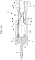
Fig. 11A} Fig. 11A illustrates the internal structure of the distal end of a treatment device according to a second embodiment of the present invention. - {
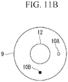
Fig. 11B} Fig. 11B is a simplified cross-sectional view taken along line XI-XI inFig. 11A . - {
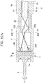
Fig. 12A} Fig. 12A illustrates the internal structure of the distal end of the treatment device inFig. 11A when the rolling joint is rotated by 180°. - {
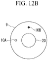
Fig. 12B} Fig. 12B is a simplified cross-sectional view taken along line XII-XII inFig. 12A . - {
Fig. 13} Fig. 13 illustrates the internal structure of the distal end according to a modification of the treatment device inFig. 11A . - {
Fig. 14} Fig. 14 illustrates the overall configuration of a surgical system according to a third embodiment of the present invention. - A treatment device 1 according to a first embodiment of the present invention will be described below with reference to
Figs. 1 to 10 . - As shown in
Figs. 1 ,2A , and2B , the treatment device 1 according to this embodiment includes a narrowmain unit 2 that is insertable into a body, anend effector 3 located at the distal end of themain unit 2, ajoint unit 4 provided between themain unit 2 and theend effector 3, amanipulation unit 5 provided at the proximal end of themain unit 2, and adriving mechanism 6 that drives thejoint unit 4 in accordance with a manipulation input to themanipulation unit 5. - The
end effector 3 is, for example, an energy device, grasping forceps, a local injection needle, a suction tube, or a clip. Theend effector 3 shown in the reference drawings is, for example, a high-frequency energy device. - The
joint unit 4 has abendable joint 7 and a rolling joint 8 in that order from the distal end thereof.Reference sign 9 denotes a substantially cylindrical housing that accommodates thejoint unit 4. - The
bendable joint 7 is provided in a bendable manner about an axis B that is orthogonal to a longitudinal axis A of themain unit 2. Specifically, thebendable joint 7 is constituted of apulley 7a and arotating shaft 7b with which thepulley 7a is attached to thehousing 9 in a rotatable manner about the axis B. Theend effector 3 is fixed to thepulley 7a such that, when the bendable joint 7 bends as a result of rotation of thepulley 7a, theend effector 3 swivels about the axis B. - The rolling joint 8 is provided in a rotatable manner about the longitudinal axis A relative to the
main unit 2. Specifically, the rolling joint 8 is formed by fitting aproximal end 9a of thehousing 9 around ashaft 2a, which is formed of the distal end of themain unit 2, in a rotatable manner in the circumferential direction. When the rolling joint 8 rotates as a result of theproximal end 9a rotating around theshaft 2a, the bendable joint 7 supported by thehousing 9 and theend effector 3 fixed to the bendable joint 7 also rotate about the longitudinal axis A together with the rolling joint 8.Figs. 2A and2B illustrate a state where the rotational angle of the rolling joint 8 is 0°. - The
manipulation unit 5 has a component, such as a dial or a joystick, to which a predetermined motion can be input. - The
driving mechanism 6 includes two wires (power transmission members) 10A and 10B extending parallel to each other from thepulley 7a to themain unit 2 via thejoint unit 4 and also includes a pullingunit 11 that pulls the proximal ends of thewires manipulation unit 5. - The two
wires pulley 7a and are wound around thepulley 7a in opposite directions from each other from their respective fixation positions. Thus, the rotational direction of thepulley 7a when one of the twowires pulley 7a when the other wire is pulled are opposite from each other, so that theend effector 3 can be swiveled about the axis B in both directions. - The pulling
unit 11 is constituted of, for example, a combination of gears and converts the motion input to themanipulation unit 5 into a motion in the direction of the longitudinal axis A so as to pull the proximal end of one of thewires wires wire unit 11 is transmitted to the distal end of thewire pulley 7a. Thus, thepulley 7a rotates clockwise or counterclockwise about the axis B, thereby causing the bendable joint 7 to bend. - The rolling joint 8 also receives the motion input to the
manipulation unit 5 via a power transmission member, such as a wire (not shown), so as to be rotationally driven. - Furthermore, the treatment device 1 according to this embodiment includes a
shaft member 12 disposed between thebendable joint 7 and themain unit 2 in the direction of the longitudinal axis A and also includes wire holders (position maintaining means) 13 and 14 that maintain the intermediate positions of the twowires shaft member 12. - The
shaft member 12 is a rigid columnar component composed of, for example, polyether ether ketone or stainless steel. The distal end of theshaft member 12 is fixed to a ring-shapedinner wall 9b protruding radially inward from the inner peripheral surface of thehousing 9, so that that theshaft member 12 also rotates together with the rolling joint 8 about the longitudinal axis A. - The wire holders are constituted of two small-diameter through-
holes 13 extending through theinner wall 9b in the direction of the longitudinal axis A and two small-diameter channels 14 extending from the distal-end surface of theshaft 2a toward the proximal end thereof in the direction of the longitudinal axis A. The two through-holes 13 are provided in theinner wall 9b at positions separated from each other by 180° in the circumferential direction. The twowires holes 13 in a movable manner in the direction of the longitudinal axis A. The twochannels 14 are provided at the radially outer side of theshaft member 12 at positions separated from each other by 180° in the circumferential direction. The twowires different channels 14 in a movable manner in the direction of the longitudinal axis A. Accordingly, in the state where the rotational angle of the rolling joint 8 is 0°, the twowires holes 13 to the distal end of themain unit 2 are arranged substantially parallel to each other at the radially outer side of theshaft member 12. - Next, the operation of the treatment device 1 having the above-described configuration will be described.
- In the treatment device 1 according to this embodiment, when a surgeon manipulates the
manipulation unit 5, thedriving mechanism 6 bends the bendable joint 7 or rotates the rolling joint 8 in accordance with the manipulation input to themanipulation unit 5. Accordingly, the position and orientation of the distal end of theend effector 3 inserted in the body can be changed via themanipulation unit 5 disposed outside the body. - The
wires bendable joint 7 and their proximal ends held within themain unit 2. Therefore, when thebendable joint 7 rotates relative to themain unit 2 in accordance with rotation of the rolling joint 8, thewires shaft member 12 between thebendable joint 7 and themain unit 2, as shown inFigs. 3A and3B .Figs. 3A and3B illustrate a state where the rotational angle of the rolling joint 8 is 180°. - However, in the through-
holes 13 at the distal end of theshaft member 12, the twowires holes 13, so that the relative positions of the twowires main unit 2 at the proximal end of theshaft member 12, the twowires channels 14, so that the relative positions of the twowires - Specifically, even in the state where the two
wires Figs. 3A and3B , the twowires wires wires unit 11 is transmitted to thepulley 7a of the bendable joint 7 with high efficiency without attenuating. This is advantageous in that good responsiveness of the bendable joint 7 to a manipulation input to themanipulation unit 5 by the surgeon can be achieved. - In this embodiment, the
wire holders wires shaft member 12. However, the relative positions of the twowires shaft member 12. For example, as shown inFig. 4 , the twowires Fig. 5 , theshaft member 12 may be disposed at a position decentered from the longitudinal axis A, and the twowires - Furthermore, as shown in
Fig. 6 , in this embodiment, the outer peripheral surface of theshaft member 12 may be provided withgrooves 12a that can accommodate thewires grooves 12a are formed at least in the outer peripheral surface of theshaft member 12 at positions where thegrooves 12a come into contact with therespective wires Fig. 6 , assuming that the center distance between the through-holes 13 is defined as L1, the center distance between thechannels 14 is defined as L2, and the distance between the through-holes 13 and thechannels 14 in the direction of the longitudinal axis A is defined as T, the contact position between thewires shaft member 12 is located distant from the distal end surface of theshaft 2a by T×L2/(L1 + L2) toward the distal end. - With this configuration, when the rolling joint 8 rotates, the
wires grooves 12a, as shown inFig. 7 , so that the position of each of thewires shaft member 12 is temporarily fixed. Consequently, thewires - Although the
shaft member 12 is fixed to the bendable joint 7 by means of thehousing 9 in this embodiment, theshaft member 12 may alternatively be provided in a rotatable manner in the circumferential direction thereof relative to thebendable joint 7, as shown inFig. 8 . In the configuration shown inFig. 8 , theshaft member 12 is supported by thehousing 9 in a rotatable manner by means of abearing 15 provided between the outer peripheral surface of theshaft member 12 and the inner peripheral surface of theinner wall 9b. - With this configuration, when the
wires shaft member 12, the force from thewires shaft member 12 to rotate in the circumferential direction, so that a frictional force between thewires shaft member 12 is reduced. Consequently, attenuation of the pulling force transmitted through thewires bendable joint 7. - Furthermore, in this embodiment, the
shaft member 12 may have ahole 12b extending therethrough in the direction of the longitudinal axis A, as shown inFig. 9 , and anextension member 16 extending from theend effector 3 to themain unit 2 may be accommodated within thehole 12b. Theextension member 16 is a small-diameter member functioning as part of theend effector 3 and extending from theend effector 3 to themain unit 2 via thejoint unit 4. For example, if theend effector 3 is an energy device, an electric wire for supplying high-frequency current is necessary. If theend effector 3 is a local injection needle, a pipe line for supplying an injection solution is necessary. If theend effector 3 is grasping forceps, a driving wire for opening and closing the grasping forceps is necessary. - The
extension member 16, such as an electric wire, a pipe line, or a driving wire, is accommodated inside theshaft member 12 at the position where twisting of thewires extension member 16 is protected from thewires end effector 3 can be properly maintained. - As shown in
Fig. 10 , theshaft member 12 may be combined with theextension member 16 into a single unit by fixing the inner peripheral surface of thehole 12b to the outer peripheral surface of theextension member 16. With this configuration, the number of components can be reduced. - Next, a treatment device according to a second embodiment of the present invention will be described with reference to
Figs. 11A to 13 . - As shown in
Figs. 11A and11B , the treatment device according to this embodiment differs from the treatment device 1 according to the first embodiment in being provided with asheath 20, which accommodates the twowires shaft member 12. Therefore, the following description of this embodiment will mainly focus on thesheath 20. Components similar to those in the first embodiment will be given the same reference signs, and descriptions thereof will be omitted. - The
sheath 20 is a columnar component composed of an elastic material, such as silicone or vinyl chloride, and has twolumens lumens wires sheath 20 are fixed to theinner wall 9b and theshaft 2a, respectively.Figs. 11A and11B illustrate a state where the rotational angle of the rolling joint 8 is 0°. - Next, the operation of the treatment device having the above-described configuration will be described.
- In the treatment device according to this embodiment, since the distal end and the proximal end of the
sheath 20 are fixed to thebendable joint 7 and themain unit 2, respectively, when thebendable joint 7 rotates relative to themain unit 2 in accordance with rotation of the rolling joint 8, thesheath 20 becomes entirely twisted, as shown inFigs. 12A and12B , thus also causing thewires sheath 20 to twist.Figs. 12A and12B illustrate a state where the rotational angle of the rolling joint 8 is 180°. - The two
wires different lumens sheath 20 and whose outer peripheral surfaces are covered by thesheath 20, do not come into contact with each other even in the twisted state. Therefore, even when the rolling joint 8 rotates, a pulling force applied to the proximal ends of thewires unit 11 is transmitted to thepulley 7a of the bendable joint 7 with high efficiency without attenuating. This is advantageous in that good responsiveness of the bendable joint 7 to a manipulation input to themanipulation unit 5 by the surgeon can be achieved. - As an alternative to this embodiment in which a
single sheath 20 having twolumens sheaths Fig. 13 , such that thesheaths wires - With this configuration, the
sheaths wires wires sheaths sheath 2. Furthermore, by providing thesheaths respective wires individual sheaths wires sheath 2. Specifically, since the elasticity required in thesheaths sheaths - Next, a
treatment device 101 and asurgical system 100 according to a third embodiment of the present invention will be described with reference toFig. 14 . - In the
surgical system 100 shown inFig. 14 , thetreatment device 101 according to this embodiment is inserted into a body via, for example, a treatment-device channel (not shown) provided in aninsertion section 30a of anendoscope 30 so as to be used for treating, for example, an affected area. - As shown in
Fig. 14 , thesurgical system 100 includes theendoscope 30 having theinsertion section 30a to be inserted into a body; amanipulation input device 31 that is to be manipulated by a surgeon (operator) O and that outputs a manipulation command; adisplay unit 32 for displaying an image acquired by theendoscope 30; a drivingdevice 33 that drives a bending section, which is provided at the distal end of theinsertion section 30a, and thejoints treatment device 101; and acontrol device 34 that controls the drivingdevice 33 in accordance with the manipulation command. For example, theinsertion section 30a is inserted into the large intestine through the anus of a patient P lying on a surgical table 35. - The
manipulation input device 31 has twomanipulation arms manipulation arm 31A is for bending the bending section of theinsertion section 30a of theendoscope 30, and themanipulation arm 31B is for manipulating thejoints treatment device 101. The surgeon O manipulates themanipulation arm 31A to appropriately bend the bending section at the distal end of theinsertion section 30a within the large intestine, so that the distal end surface protruding from the distal end of thetreatment device 101 faces the affected area. - In this embodiment, the
treatment device 101 differs from the treatment device 1 in the first and second embodiments described above in that thejoints device 33 instead of being driven by themanipulation unit 5 and thedriving mechanism 6. Other components of thetreatment device 101 are similar to those of the treatment device according to the first or second embodiment. - The driving
device 33 has an electric motor (not shown). The electric motor pulls the proximal end of thewire control device 34, whereby thebendable joint 7 is driven. Furthermore, the drivingdevice 33 also rotationally drives the rolling joint 8 on the basis of a command signal from thecontrol device 34. - Next, the operation of the
treatment device 101 and thesurgical system 100 according to this embodiment, having the above-described configuration, will be described below. - In the
surgical system 100, when a manipulation command is input to thecontrol device 34 as a result of a manipulation performed on themanipulation arm 31B of themanipulation input device 31, thecontrol device 34 actuates the drivingdevice 33 of thetreatment device 101, and the drivingdevice 33 bends the bendable joint 7 or rotates the rolling joint 8 in accordance with the manipulation input to themanipulation arm 31B. - Accordingly, in this embodiment, the driving
device 33 that generates a driving force for the joint 7 or 8 in response to an electrical command signal from thecontrol device 34 is provided. This is advantageous in that the joint 7 or 8 can be driven by means of themanipulation input device 31 provided separately from themain unit 2 of thetreatment device 101. Since other advantages of this embodiment are similar to those of the first and second embodiments, descriptions thereof will be omitted. - The articulated structures of the
treatment devices 1 and 101 described in the first to third embodiments are merely examples and are modifiable, where appropriate. For example, the number of joints may be two or three or more. Furthermore, although thebendable joint 7 is described as a driven joint provided between theend effector 3 and the rolling joint 8, the driven joint may be a type of joint other than thebendable joint 7 and may be a joint provided in the end effector 3 (e.g., a joint for opening and closing grasping forceps). - Furthermore, although the
wires -
- 1, 101
- treatment device
- 2
- main unit
- 3
- end effector
- 4
- joint unit
- 5
- manipulation unit
- 6
- driving mechanism
- 7
- bendable joint (driven joint)
- 7a
- pulley
- 7b
- rotating shaft
- 8
- rolling joint
- 9
- housing
- 9a
- proximal end
- 9b
- inner wall
- 10A, 10B
- wire (power transmission member)
- 11
- pulling unit
- 12
- shaft member
- 12a
- groove
- 12b
- hole
- 13
- wire holder, through-hole (position maintaining means)
- 14
- wire holder, channel (position maintaining means)
- 15
- bearing
- 16
- extension member
- 20, 201, 202
- sheath
- 20A, 20B
- lumen
- 30
- endoscope
- 30a
- insertion section
- 31
- manipulation input device
- 32
- display unit
- 33
- driving device
- 34
- control device
- 35
- surgical table
- 100
- surgical system
Claims (10)
- A treatment device comprising:a narrow main unit;an end effector located at a distal end of the main unit;a rolling joint that is provided between the end effector and the main unit and that is rotatable relative to the main unit about a longitudinal axis of the main unit;a driven joint that is provided at the end effector or between the end effector and the rolling joint and that rotates together with the rolling joint about the longitudinal axis;a plurality of linear power transmission members that extend parallel to each other from the driven joint to the main unit via the rolling joint and that transmit power applied to proximal ends;a position maintaining means that maintains the plurality of power transmission members at predetermined relative positions, which are two positions located between the driven joint and the main unit and separated from each other by a certain distance in a direction of the longitudinal axis; anda columnar shaft member disposed in the direction of the longitudinal axis between the two positions,wherein the position maintaining means maintains the plurality of power transmission members at the relative positions located at a radially outer side of the shaft member and separated from each other by the certain distance in a circumferential direction of the shaft member.
- The treatment device according to Claim 1,
wherein the shaft member is provided in a rotatable manner in the circumferential direction relative to the driven joint. - The treatment device according to Claim 1 or 2, further comprising:a small-diameter extension member whose distal end is connected to the end effector and that extends from the end effector to the main unit,wherein the shaft member has a hole extending therethrough in the direction of the longitudinal axis and accommodating a longitudinal section of the extension member.
- The treatment device according to Claim 3,
wherein the shaft member is fixed to an outer peripheral surface of the extension member. - The treatment device according to any one of Claims 1 to 4,
wherein the shaft member has a groove that extends in the circumferential direction and that is located at a position where an outer peripheral surface of the shaft member comes into contact with the power transmission members when the rolling joint rotates. - The treatment device according to any one of Claims 1 to 5,
wherein the end effector is an energy device, grasping forceps, a local injection needle, a suction tube, or a clip. - A treatment device comprising:a narrow main unit;an end effector located at a distal end of the main unit;a rolling joint that is provided between the end effector and the main unit and that is rotatable relative to the main unit about a longitudinal axis of the main unit;a driven joint that is provided at the end effector or between the end effector and the rolling joint and that rotates together with the rolling joint about the longitudinal axis;a plurality of linear power transmission members that extend parallel to each other from the driven joint to the main unit via the rolling joint and that transmit power applied to proximal ends; anda tubular sheath that is composed of an elastic material and that covers outer peripheral surfaces of the plurality of power transmission members between the driven joint and the main unit.
- The treatment device according to Claim 7,
wherein the sheath is formed of a single component having a plurality of lumens extending therethrough in a longitudinal direction, and
wherein the power transmission members are respectively inserted through the plurality of lumens. - The treatment device according to Claim 7,
wherein a plurality of the sheaths are provided individually for the respective power transmission members. - A surgical system comprising:the treatment device according to any one of Claims 1 to 9;a manipulation input device that is to be manipulated by an operator;a driving device that drives at least one of the rolling joint and the driven joint; anda control device that controls the driving device on the basis of a manipulation input to the manipulation input device.
Applications Claiming Priority (2)
| Application Number | Priority Date | Filing Date | Title |
|---|---|---|---|
| JP2014080193A JP6296869B2 (en) | 2014-04-09 | 2014-04-09 | Treatment instrument and surgical system |
| PCT/JP2015/053852 WO2015156026A1 (en) | 2014-04-09 | 2015-02-12 | Treatment tool and surgical system |
Publications (2)
| Publication Number | Publication Date |
|---|---|
| EP3130304A1 true EP3130304A1 (en) | 2017-02-15 |
| EP3130304A4 EP3130304A4 (en) | 2017-12-20 |
Family
ID=54287607
Family Applications (1)
| Application Number | Title | Priority Date | Filing Date |
|---|---|---|---|
| EP15776442.4A Withdrawn EP3130304A4 (en) | 2014-04-09 | 2015-02-12 | Treatment tool and surgical system |
Country Status (5)
| Country | Link |
|---|---|
| US (1) | US20170007346A1 (en) |
| EP (1) | EP3130304A4 (en) |
| JP (1) | JP6296869B2 (en) |
| CN (1) | CN106102627B (en) |
| WO (1) | WO2015156026A1 (en) |
Families Citing this family (6)
| Publication number | Priority date | Publication date | Assignee | Title |
|---|---|---|---|---|
| KR102742976B1 (en) * | 2016-02-05 | 2024-12-16 | 보드 오브 리전츠, 더 유니버시티 오브 텍사스 시스템 | Surgical apparatus |
| JP6761482B2 (en) | 2016-12-28 | 2020-09-23 | オリンパス株式会社 | Medical systems, medical overtubes, and medical device adapters |
| DE102017112941A1 (en) | 2017-06-13 | 2018-12-13 | Imt Ag | Surface coating for a medical instrument, medical instrument with a surface coating and method for producing a surface coating for a medical instrument |
| CN114073483A (en) * | 2021-11-30 | 2022-02-22 | 中北大学 | Miniature intestinal examination robot based on rope-pulling type flexible reducing |
| CN115381380A (en) * | 2022-09-06 | 2022-11-25 | 北京罗森博特科技有限公司 | Endoscope bracket with mechanical locking function |
| CN119074229B (en) * | 2024-09-02 | 2026-04-14 | 瑞龙诺赋(上海)医疗科技有限公司 | Instrument joint set and surgical instrument comprising same |
Family Cites Families (20)
| Publication number | Priority date | Publication date | Assignee | Title |
|---|---|---|---|---|
| JP3363853B2 (en) * | 1999-11-17 | 2003-01-08 | 株式会社日立製作所 | Treatment tool |
| US6746443B1 (en) * | 2000-07-27 | 2004-06-08 | Intuitive Surgical Inc. | Roll-pitch-roll surgical tool |
| US20030135204A1 (en) * | 2001-02-15 | 2003-07-17 | Endo Via Medical, Inc. | Robotically controlled medical instrument with a flexible section |
| US20060199999A1 (en) * | 2001-06-29 | 2006-09-07 | Intuitive Surgical Inc. | Cardiac tissue ablation instrument with flexible wrist |
| US6817974B2 (en) * | 2001-06-29 | 2004-11-16 | Intuitive Surgical, Inc. | Surgical tool having positively positionable tendon-actuated multi-disk wrist joint |
| US6676684B1 (en) * | 2001-09-04 | 2004-01-13 | Intuitive Surgical, Inc. | Roll-pitch-roll-yaw surgical tool |
| JP2004154164A (en) * | 2002-11-01 | 2004-06-03 | Mizuho Co Ltd | Multi-degree-of-freedom type treating instrument |
| ITPI20030107A1 (en) * | 2003-11-14 | 2005-05-15 | Massimo Bergamasco | DEVICE FOR PERFORMING OPERATIONS |
| JP4300169B2 (en) * | 2004-09-10 | 2009-07-22 | アロカ株式会社 | Ultrasound surgical device |
| AU2006222753B2 (en) * | 2005-09-30 | 2012-09-27 | Ethicon Endo-Surgery, Inc. | Electroactive polymer-based actuation mechanism for linear surgical stapler |
| JP4425223B2 (en) * | 2006-02-17 | 2010-03-03 | Hoya株式会社 | High frequency knife for endoscope |
| US7831786B2 (en) * | 2006-05-08 | 2010-11-09 | Research In Motion Limited | Sharing memory resources of wireless portable electronic devices |
| US8105350B2 (en) * | 2006-05-23 | 2012-01-31 | Cambridge Endoscopic Devices, Inc. | Surgical instrument |
| US8137263B2 (en) * | 2007-08-24 | 2012-03-20 | Karl Storz Endovision, Inc. | Articulating endoscope instrument |
| KR20090119366A (en) * | 2008-05-16 | 2009-11-19 | 한국과학기술원 | Laparoscopic Surgery Robot with Freedom of Freedom |
| US8245594B2 (en) * | 2008-12-23 | 2012-08-21 | Intuitive Surgical Operations, Inc. | Roll joint and method for a surgical apparatus |
| FR2943907B1 (en) * | 2009-04-03 | 2012-08-03 | Univ Pierre Et Marie Curie Paris 6 | SURGICAL INSTRUMENT. |
| TW201105154A (en) * | 2009-07-22 | 2011-02-01 | Inst Information Industry | Mobile node, WiMAX base station, Wi-Fi access point and handover method thereof for use in a heterogeneous wirelesss network system |
| US9339341B2 (en) * | 2010-02-08 | 2016-05-17 | Intuitive Surgical Operations, Inc. | Direct pull surgical gripper |
| JP5065546B2 (en) * | 2010-10-28 | 2012-11-07 | オリンパスメディカルシステムズ株式会社 | Treatment tool |
-
2014
- 2014-04-09 JP JP2014080193A patent/JP6296869B2/en active Active
-
2015
- 2015-02-12 CN CN201580014099.3A patent/CN106102627B/en active Active
- 2015-02-12 EP EP15776442.4A patent/EP3130304A4/en not_active Withdrawn
- 2015-02-12 WO PCT/JP2015/053852 patent/WO2015156026A1/en not_active Ceased
-
2016
- 2016-09-24 US US15/275,349 patent/US20170007346A1/en not_active Abandoned
Also Published As
| Publication number | Publication date |
|---|---|
| JP2015198819A (en) | 2015-11-12 |
| EP3130304A4 (en) | 2017-12-20 |
| JP6296869B2 (en) | 2018-03-20 |
| WO2015156026A1 (en) | 2015-10-15 |
| CN106102627A (en) | 2016-11-09 |
| CN106102627B (en) | 2019-02-12 |
| US20170007346A1 (en) | 2017-01-12 |
Similar Documents
| Publication | Publication Date | Title |
|---|---|---|
| US20170007346A1 (en) | Treatment device and surgical system | |
| US11147642B2 (en) | Systems, devices, and methods for performing surgical actions via externally driven driving assemblies | |
| US9677599B2 (en) | Insertion body, insertion apparatus, rotation unit and rotative force transmission unit | |
| EP3025674B1 (en) | Therapeutic manipulator and manipulator system | |
| EP3305229A1 (en) | Medical manipulator | |
| EP3321047A1 (en) | Surgical robot | |
| US20160100746A1 (en) | Endoscope, overtube, and endoscope system | |
| KR20130038261A (en) | Navigated malleable surgical instrument | |
| JP2006218232A (en) | Endoscopic flexible tube and endoscope apparatus | |
| JP6482101B2 (en) | Operation unit for bending treatment tools | |
| CN106231983B (en) | Treatment apparatus adapter, endoscope and endoscopic system | |
| JP2007289703A (en) | Medical cannula and medical cannula system | |
| CN101061943B (en) | Medical tubular assembly | |
| EP3158909B1 (en) | Guiding device and surgical system | |
| JP2019103804A (en) | Probe applicator | |
| EP3031382B1 (en) | Medical device | |
| EP2123231B1 (en) | Bending tube and medical apparatus | |
| JP6284182B2 (en) | Operation unit for bending treatment tools | |
| EP3311729A1 (en) | Joint ring and medical manipulator | |
| US20220015848A1 (en) | Systems, devices, and methods for performing surgical actions via externally driven driving assemblies | |
| US12544170B2 (en) | Medical manipulator | |
| WO2021255877A1 (en) | Long medical device | |
| JP5865559B1 (en) | Surgical endoscope device | |
| US20260033706A1 (en) | Medical manipulator and medical manipulator system | |
| US20210259529A1 (en) | Guide tube, treatment system and guide-tube attachment method |
Legal Events
| Date | Code | Title | Description |
|---|---|---|---|
| STAA | Information on the status of an ep patent application or granted ep patent |
Free format text: STATUS: THE INTERNATIONAL PUBLICATION HAS BEEN MADE |
|
| PUAI | Public reference made under article 153(3) epc to a published international application that has entered the european phase |
Free format text: ORIGINAL CODE: 0009012 |
|
| STAA | Information on the status of an ep patent application or granted ep patent |
Free format text: STATUS: REQUEST FOR EXAMINATION WAS MADE |
|
| 17P | Request for examination filed |
Effective date: 20161017 |
|
| AK | Designated contracting states |
Kind code of ref document: A1 Designated state(s): AL AT BE BG CH CY CZ DE DK EE ES FI FR GB GR HR HU IE IS IT LI LT LU LV MC MK MT NL NO PL PT RO RS SE SI SK SM TR |
|
| AX | Request for extension of the european patent |
Extension state: BA ME |
|
| DAX | Request for extension of the european patent (deleted) | ||
| A4 | Supplementary search report drawn up and despatched |
Effective date: 20171122 |
|
| RIC1 | Information provided on ipc code assigned before grant |
Ipc: A61B 17/28 20060101ALI20171116BHEP Ipc: A61B 17/29 20060101ALN20171116BHEP Ipc: A61B 90/00 20160101ALN20171116BHEP Ipc: A61B 34/30 20160101ALI20171116BHEP Ipc: A61B 18/12 20060101ALN20171116BHEP Ipc: A61B 34/00 20160101AFI20171116BHEP |
|
| STAA | Information on the status of an ep patent application or granted ep patent |
Free format text: STATUS: THE APPLICATION IS DEEMED TO BE WITHDRAWN |
|
| 18D | Application deemed to be withdrawn |
Effective date: 20200901 |