EP3130293A2 - Adapter assembly for interconnecting electromechanical surgical devices and surgical loading units, and surgical systems thereof - Google Patents
Adapter assembly for interconnecting electromechanical surgical devices and surgical loading units, and surgical systems thereof Download PDFInfo
- Publication number
- EP3130293A2 EP3130293A2 EP16183520.2A EP16183520A EP3130293A2 EP 3130293 A2 EP3130293 A2 EP 3130293A2 EP 16183520 A EP16183520 A EP 16183520A EP 3130293 A2 EP3130293 A2 EP 3130293A2
- Authority
- EP
- European Patent Office
- Prior art keywords
- proximal
- loading unit
- distal
- surgical device
- drive shaft
- Prior art date
- Legal status (The legal status is an assumption and is not a legal conclusion. Google has not performed a legal analysis and makes no representation as to the accuracy of the status listed.)
- Granted
Links
Images
















Classifications
-
- A—HUMAN NECESSITIES
- A61—MEDICAL OR VETERINARY SCIENCE; HYGIENE
- A61B—DIAGNOSIS; SURGERY; IDENTIFICATION
- A61B17/00—Surgical instruments, devices or methods
- A61B17/068—Surgical staplers, e.g. containing multiple staples or clamps
- A61B17/072—Surgical staplers, e.g. containing multiple staples or clamps for applying a row of staples in a single action, e.g. the staples being applied simultaneously
-
- A—HUMAN NECESSITIES
- A61—MEDICAL OR VETERINARY SCIENCE; HYGIENE
- A61B—DIAGNOSIS; SURGERY; IDENTIFICATION
- A61B17/00—Surgical instruments, devices or methods
- A61B17/068—Surgical staplers, e.g. containing multiple staples or clamps
- A61B17/072—Surgical staplers, e.g. containing multiple staples or clamps for applying a row of staples in a single action, e.g. the staples being applied simultaneously
- A61B17/07207—Surgical staplers, e.g. containing multiple staples or clamps for applying a row of staples in a single action, e.g. the staples being applied simultaneously the staples being applied sequentially
-
- A—HUMAN NECESSITIES
- A61—MEDICAL OR VETERINARY SCIENCE; HYGIENE
- A61B—DIAGNOSIS; SURGERY; IDENTIFICATION
- A61B17/00—Surgical instruments, devices or methods
- A61B2017/00017—Electrical control of surgical instruments
-
- A—HUMAN NECESSITIES
- A61—MEDICAL OR VETERINARY SCIENCE; HYGIENE
- A61B—DIAGNOSIS; SURGERY; IDENTIFICATION
- A61B17/00—Surgical instruments, devices or methods
- A61B2017/00367—Details of actuation of instruments, e.g. relations between pushing buttons, or the like, and activation of the tool, working tip, or the like
- A61B2017/00398—Details of actuation of instruments, e.g. relations between pushing buttons, or the like, and activation of the tool, working tip, or the like using powered actuators, e.g. stepper motors, solenoids
-
- A—HUMAN NECESSITIES
- A61—MEDICAL OR VETERINARY SCIENCE; HYGIENE
- A61B—DIAGNOSIS; SURGERY; IDENTIFICATION
- A61B17/00—Surgical instruments, devices or methods
- A61B2017/0046—Surgical instruments, devices or methods with a releasable handle; with handle and operating part separable
-
- A—HUMAN NECESSITIES
- A61—MEDICAL OR VETERINARY SCIENCE; HYGIENE
- A61B—DIAGNOSIS; SURGERY; IDENTIFICATION
- A61B17/00—Surgical instruments, devices or methods
- A61B2017/0046—Surgical instruments, devices or methods with a releasable handle; with handle and operating part separable
- A61B2017/00473—Distal part, e.g. tip or head
-
- A—HUMAN NECESSITIES
- A61—MEDICAL OR VETERINARY SCIENCE; HYGIENE
- A61B—DIAGNOSIS; SURGERY; IDENTIFICATION
- A61B17/00—Surgical instruments, devices or methods
- A61B2017/00477—Coupling
-
- A—HUMAN NECESSITIES
- A61—MEDICAL OR VETERINARY SCIENCE; HYGIENE
- A61B—DIAGNOSIS; SURGERY; IDENTIFICATION
- A61B17/00—Surgical instruments, devices or methods
- A61B2017/00681—Aspects not otherwise provided for
- A61B2017/00734—Aspects not otherwise provided for battery operated
Definitions
- the present disclosure relates to adapter assemblies for use in surgical systems. More specifically, the present disclosure relates to adapter assemblies for use with and to electrically and mechanically interconnect electromechanical surgical devices and surgical loading units, and to surgical systems including hand held electromechanical surgical devices and adapter assemblies for connecting surgical loading units to the hand held electromechanical surgical devices.
- the electromechanical surgical devices include a handle assembly, which is reusable, and disposable loading units and/or single use loading units or the like that are selectively connected to the handle assembly prior to use and then disconnected from the handle assembly following use in order to be disposed of or in some instances sterilized for re-use.
- an adapter assembly is used to interconnect an electromechanical surgical device with any one of a number of surgical loading units to establish a mechanical and/or electrical connection therebetween.
- an overall length of this electromechanical surgical system tends to be relatively greater/longer as compared to an electromechanical surgical system not using an adapter assembly.
- This increased length of the electromechanical surgical system tends to move a center of gravity of the electromechanical surgical system (including an adapter assembly) relatively distal of a center of gravity of another electromechanical surgical system (not including an adapter assembly).
- an adapter assembly that has a relatively shorter length and that reduces the distal displacement of a center of gravity of the electromechanical surgical system.
- the present disclosure relates to adapter assemblies for use with and to electrically and mechanically interconnect electromechanical surgical devices and surgical loading units, and to surgical systems including hand held electromechanical surgical devices and adapter assemblies for connecting surgical loading units to the hand held electromechanical surgical devices.
- an adapter assembly for selectively interconnecting a surgical loading unit that is configured to perform a function and a surgical device that is configured to actuate the loading unit, is provided.
- the loading unit may include at least one axially translatable drive member, and the surgical device may include at least one rotatable drive shaft.
- the adapter assembly may include a housing configured and adapted for connection with the surgical device and configured and adapted to be in operative communication with each rotatable drive shaft of the surgical device; an outer tube having a proximal end supported by the housing and a distal end configured and adapted for connection with the loading unit, wherein the distal end of the outer tube is in operative communication with each of the axially translatable drive member of the loading unit; and the force/rotation transmitting/converting assembly for interconnecting a respective one drive shaft of the surgical device and a respective one axially translatable drive member of the loading unit.
- the force/rotation transmitting/converting assembly may include a proximal rotation receiving member that is connectable to the respective drive shaft of the surgical device defining a threaded distal end; and a distal force transmitting member that is connectable to an articulation link of the axially translatable drive member of the loading unit.
- the distal force transmitting member may include a bearing assembly having an outer race threadably connected to the threaded distal end of the proximal drive shaft and an inner race; a distal articulation bar having a proximal end and a distal end, the distal end of the distal articulation bar being configured to selectively engage the axially translatable drive member of the loading unit; a proximal articulation bar having a proximal end and a distal end, the distal end of the proximal articulation bar being secured to the proximal end of the distal articulation bar; and a collar integrally supported at the proximal end of the proximal articulation bar, the collar having an outer diameter substantially equal to an outer diameter of the inner race of the bearing assembly; wherein the force/rotation transmitting/converting assembly converts and transmits a rotation of the rotatable drive shaft of the surgical device to an axial translation of the axially translatable drive member of the loading unit.
- the outer diameter of the collar may be greater than the outer diameter of the transition portion such that the distal articulation bar and the proximal articulation bar resist bending during use.
- the distal end of the proximal articulation bar may define a cut-out configured for mating with the proximal end of the distal articulation bar.
- the outer race of the bearing assembly may include a first through hole and a second through hole, the first and second through holes intersecting to define a cavity in the outer race configured for housing a ball having a threaded bore formed therein, the threaded bore configured for threadably connecting to the threaded distal end of the proximal drive shaft.
- the adapter assembly may include a housing configured and adapted for connection with the surgical device and configured and adapted to be in operative communication with each rotatable drive shaft of the surgical device; an outer tube having a proximal end supported by the housing and a distal end configured and adapted for connection with the loading unit, wherein the distal end of the outer tube is in operative communication with each of the axially translatable drive member of the loading unit; and the force/rotation transmitting/converting assembly for interconnecting a respective one drive shaft of the surgical device and a respective one axially translatable drive member of the loading unit.
- the distal force transmitting member may include an articulation bar extending longitudinally between a proximal end and a distal end, the distal end of the articulation bar being configured to selectively engage the axially translatable drive member of the loading unit; a bearing assembly having an outer race threadably connected to the threaded distal end of the proximal drive shaft, and an inner race; and an inner sleeve supported in the inner race of the bearing assembly and extending axially from the inner race, the inner sleeve including an inner diameter and an outer diameter, the outer diameter defining a slot configured for disposal of the proximal end of the articulation bar such that the proximal end of the articulation bar is disposed between the inner race of the bearing assembly and the outer diameter of the inner sleeve; wherein the force/rotation transmitting/converting assembly converts and transmits a rotation of the rotatable drive shaft of the surgical device to an axial translation of the axially translatable drive member of the loading unit.
- the housing may include a slip ring cannula disposed within the inner sleeve such that an outer diameter of the slip ring cannula engages the inner diameter of the inner sleeve utilizing an interference fit.
- an adapter assembly for selectively interconnecting a surgical loading unit that is configured to perform a function and a surgical device that is configured to actuate the loading unit.
- the loading unit may include at least one axially translatable drive member, and the surgical device may include at least one rotatable drive shaft.
- the adapter assembly may include a housing configured and adapted for connection with the surgical device and configured and adapted to be in operative communication with each rotatable drive shaft of the surgical device; an outer tube having a proximal end supported by the housing and a distal end configured and adapted for connection with the loading unit, wherein the distal end of the outer tube is in operative communication with each of the axially translatable drive member of the loading unit; and the force/rotation transmitting/converting assembly for interconnecting a respective one drive shaft of the surgical device and a respective one axially translatable drive member of the loading unit.
- the at least one force/rotation transmitting/converting assembly may include a proximal rotation receiving member that is connectable to a respective rotatable drive shaft of the surgical device, the proximal rotation receiving member defining at least one spur gear; a driver including an outer surface defining at least one spur gear configured for mating with the spur gear of the proximal rotation receiving member, the driver defining a bore therethrough, the bore having an inner surface defining at least one thread; and a distal force transmitting member that is connectable to an articulation link of the axially translatable drive member of the loading unit.
- the distal force transmitting member may include a sleeve having an outer surface defining at least one thread configured to mate with the inner surface of the driver; and an articulation bar having a proximal end secured to the sleeve and a distal end configured to selectively engage the axially translatable drive member of the loading unit; wherein the force/rotation transmitting/converting assembly converts and transmits a rotation of the rotatable drive shaft of the surgical device to a rotation of the driver such that the sleeve of the distal force transmitting member is axially translated resulting in an axial translation of the axially translatable drive member of the loading unit.
- the distal plate may include a second through hole configured for locating a distal protrusion of the proximal rotation receiving member such that when the distal boss of the driver is located in the first through hole and the distal protrusion of the proximal rotation receiving member is located in the second through hole, the at least one spur gear of the driver is mated with the at least one spur gear of the proximal rotation receiving member.
- the housing may define a proximal core portion configured for location a proximal boss of the driver such that the driver is mounted co-axial to the longitudinal axis.
- the sleeve defines a bore therethrough which defines an inner surface, and wherein the proximal end of the articulation bar is secured to the inner surface of the sleeve.
- distal refers to that portion of the adapter assembly or surgical device, or component thereof, farther from the user
- proximal refers to that portion of the adapter assembly or surgical device, or component thereof, closer to the user.
- a surgical device in accordance with an embodiment of the present disclosure, is generally designated as 100, and is in the form of a powered hand held electromechanical instrument configured for selective attachment thereto of a plurality of different end effectors that are each configured for actuation and manipulation by the powered hand held electromechanical surgical instrument.
- surgical device 100 is configured for selective connection with an adapter assembly 200, and, in turn, adapter assembly 200 is configured for selective connection with a loading unit 300 (e.g., an end effector, multiple- or single-use loading unit, see FIG. 48 ).
- Surgical device 100 and adapter assembly 200 may comprise an electromechanical surgical system that is configured and adapted to selectively connect with a loading unit 300 and to actuate loading unit 300.
- surgical device 100 includes a handle housing 102 including a circuit board (not shown) and a drive mechanism (not shown) is situated therein.
- the circuit board is configured to control the various operations of surgical device 100.
- Handle housing 102 defines a cavity therein (not shown) for selective removable receipt of a rechargeable battery (not shown) therein.
- the battery is configured to supply power to any of the electrical components of surgical device 100.
- Handle housing 102 includes an upper housing portion 102a which houses various components of surgical device 100, and a lower hand grip portion 102b extending from upper housing portion 102a.
- Lower hand grip portion 102b may be disposed distally of a proximal-most end of upper housing portion 102a. The location of lower housing portion 102b relative to upper housing portion 102a is selected to balance a weight of a surgical device 100 that is connected to or supporting adapter assembly 200 and/or end effector 300.
- handle housing 102 defines a connecting portion 108 configured to accept a corresponding drive coupling assembly 210 of adapter assembly 200.
- connecting portion 108 of surgical device 100 has a recess 108a that receives a proximal cap 210a ( FIG. 6 ) of drive coupling assembly 210 of adapter assembly 200 when adapter assembly 200 is mated to surgical device 100.
- Connecting portion 108 houses three rotatable drive connectors 118, 120, 122 which are arranged in a common plane or line with one another.
- each of rotatable drive connectors 118, 120, 122 of surgical device 100 couples with a corresponding rotatable connector sleeve 218, 220, 222 of adapter assembly 200.
- the interface between corresponding first drive connector 118 and first connector sleeve 218, the interface between corresponding second drive connector 120 and second connector sleeve 220, and the interface between corresponding third drive connector 122 and third connector sleeve 222 are keyed such that rotation of each of drive connectors 118, 120, 122 of surgical device 100 causes a corresponding rotation of the corresponding connector sleeve 218, 220, 222 of adapter assembly 200.
- drive connectors 118, 120, 122 of surgical device 100 with connector sleeves 218, 220, 222 of adapter assembly 200 allows rotational forces to be independently transmitted via each of the three respective connector interfaces.
- the drive connectors 118, 120, 122 of surgical device 100 are configured to be independently rotated by the drive mechanism of surgical device 100.
- a function selection module (not shown) of the drive mechanism selects which drive connector or connectors 118, 120, 122 of surgical device 100 is to be driven by the motor of surgical device 100.
- each of drive connectors 118, 120, 122 of surgical device 100 has a keyed and/or substantially non-rotatable interface with respective connector sleeves 218, 220, 222 of adapter assembly 200, when adapter assembly 200 is coupled to surgical device 100, rotational force(s) are selectively transferred from drive connectors of surgical device 100 to adapter assembly 200.
- handle housing 102 supports a plurality of finger-actuated control buttons, rocker devices and the like for activating various functions of surgical device 100.
- adapter assembly 200 includes an outer knob housing 202 and an outer tube 206 extending from a distal end of knob housing 202.
- Knob housing 202 and outer tube 206 are configured and dimensioned to house the components of adapter assembly 200.
- Outer tube 206 is dimensioned for endoscopic insertion, in particular, that outer tube is passable through a typical trocar port, cannula or the like.
- Knob housing 202 is dimensioned to not enter the trocar port, cannula of the like.
- Knob housing 202 is configured and adapted to connect to connecting portion 108 of handle housing 102 of surgical device 100.
- Adapter assembly 200 is configured to convert a rotation of either of drive connectors 118 and 120 of surgical device 100 into axial translation useful for operating a drive assembly 360 and an articulation link 366 of loading unit 300, as illustrated in FIG. 48 and as will be described in greater detail below.
- adapter assembly 200 includes a proximal inner housing assembly 204 rotatably supporting a first rotatable proximal drive shaft 212, a second rotatable proximal drive shaft 214, and a third rotatable proximal drive shaft 216 therein.
- Each proximal drive shaft 212, 214, 216 functions as a rotation receiving member to receive rotational forces from respective drive shafts of surgical device 100, as described in greater detail below.
- inner housing assembly 204 of shaft assembly 200 is also configured to rotatably support first, second and third connector sleeves 218, 220 and 222, respectively, arranged in a common plane or line with one another.
- Each of connector sleeves 218, 220, 222 is configured to mate with respective first, second and third drive connectors 118, 120, 122 of surgical device 100, as described above.
- Each of connector sleeves 218, 220, 222 is further configured to mate with a proximal end of respective first, second and third proximal drive shafts 212, 214, 216.
- Inner housing assembly 204 also includes, as illustrated in FIGS. 6 , 17 , 27 and 28 , a first, a second and a third biasing member 224, 226 and 228 disposed distally of respective first, second and third connector sleeves 218, 220, 222.
- Each of biasing members 224, 226 and 228 is disposed about respective first, second and third rotatable proximal drive shaft 212, 214 and 216.
- Biasing members 224, 226 and 228 act on respective connector sleeves 218, 220 and 222 to help maintain connector sleeves 218, 220 and 222 engaged with the distal end of respective drive rotatable drive connectors 118, 120, 122 of surgical device 100 when adapter assembly 200 is connected to surgical device 100.
- first, second and third biasing members 224, 226 and 228 function to bias respective connector sleeves 218, 220 and 222 in a proximal direction. In this manner, during assembly of adapter assembly 200 to surgical device 100, if first, second and or third connector sleeves 218, 220 and/or 222 is/are misaligned with the drive connectors 118, 120, 122 of surgical device 100, first, second and/or third biasing member(s) 224, 226 and/or 228 are compressed.
- drive connectors 118, 120, 122 of surgical device 100 will rotate and first, second and/or third biasing member(s) 224, 226 and/or 228 will cause respective first, second and/or third connector sleeve(s) 218, 220 and/or 222 to slide back proximally, effectively coupling drive connectors 118, 120, 122 of surgical device 100 to first, second and/or third proximal drive shaft(s) 212, 214 and 216 of inner housing assembly 204.
- Adapter assembly 200 includes a plurality of force/rotation transmitting/converting assemblies, each disposed within inner housing assembly 204 and outer tube 206. Each force/rotation transmitting/converting assembly is configured and adapted to transmit/convert a speed/force of rotation (e.g., increase or decrease) of first, second and third rotatable drive connectors 118, 120 and 122 of surgical instrument 100 before transmission of such rotational speed/force to loading unit 300.
- a speed/force of rotation e.g., increase or decrease
- adapter assembly 200 includes a first, a second and a third force/rotation transmitting/converting assembly 240, 250, 260, respectively, disposed within inner housing 208 and outer tube 206.
- Each force/rotation transmitting/converting assembly 240, 250, 260 is configured and adapted to transmit or convert a rotation of a first, second and third drive connector 118, 120, 122 of surgical device 100 into axial translation of articulation bar 258 of adapter assembly 200, to effectuate articulation of loading unit 300; a rotation of a ring gear 266 of adapter assembly 200, to effectuate rotation of adapter assembly 200; or axial translation of a distal drive member 248 of adapter assembly 200 to effectuate closing, opening and firing of loading unit 300.
- first force/rotation transmitting/converting assembly 240 includes first rotatable proximal drive shaft 212, which, as described above, is rotatably supported within inner housing assembly 204.
- First rotatable proximal drive shaft 212 includes a non-circular proximal end portion configured for connection with first connector 218 which is connected to respective first connector 118 of surgical device 100.
- First rotatable proximal drive shaft 212 includes a distal end portion 212b having a threaded outer profile or surface.
- First force/rotation transmitting/converting assembly 240 further includes a drive coupling nut 244 rotatably coupled to threaded distal end portion 212b of first rotatable proximal drive shaft 212, and which is slidably disposed within outer tube 206.
- Drive coupling nut 244 is slidably keyed within proximal core tube portion of outer tube 206 so as to be prevented from rotation as first rotatable proximal drive shaft 212 is rotated.
- first rotatable proximal drive shaft 212 is rotated, drive coupling nut 244 is translated along threaded distal end portion 212b of first rotatable proximal drive shaft 212 and, in turn, through and/or along outer tube 206.
- First force/rotation transmitting/converting assembly 240 further includes a distal drive member 248 that is mechanically engaged with drive coupling nut 244, such that axial movement of drive coupling nut 244 results in a corresponding amount of axial movement of distal drive member 248.
- the distal end portion of distal drive member 248 supports a connection member 247 configured and dimensioned for selective engagement with a drive member 374 of drive assembly 360 of loading unit 300 ( FIG. 48 ).
- Drive coupling nut 244 and/or distal drive member 248 function as a force transmitting member to components of loading unit 300, as described in greater detail below.
- first rotatable proximal drive shaft 212 is rotated, due to a rotation of first connector sleeve 218, as a result of the rotation of the first respective drive connector 118 of surgical device 100, drive coupling nut 244 is caused to be translated axially along first distal drive shaft 242.
- drive coupling nut 244 is caused to be translated axially along first distal drive shaft 242
- distal drive member 248 is caused to be translated axially relative to outer tube 206.
- distal drive member 248 causes concomitant axial translation of drive member 374 of loading unit 300 to effectuate a closure of tool assembly 304 and a firing of tool assembly 304 of loading unit 300.
- second drive converter assembly 250 of adapter assembly 200 includes second proximal drive shaft 214 rotatably supported within inner housing assembly 204.
- Second rotatable proximal drive shaft 214 includes a non-circular proximal end portion configured for connection with second connector or coupler 220 which is connected to respective second connector 120 of surgical device 100.
- Second rotatable proximal drive shaft 214 further includes a distal end portion 214b having a threaded outer profile or surface.
- Articulation bearing assembly 252 includes a housing 252a supporting an articulation bearing 253 having an inner race 253b that is independently rotatable relative to an outer race 253a.
- Articulation bearing housing 252a has a non-circular outer profile, for example tear-drop shaped, that is slidably and non-rotatably disposed within a complementary bore 204c ( FIGS. 25, 26 , 29 and 33 ) of inner housing hub 204a.
- Second drive converter assembly 250 of adapter assembly 200 further includes an articulation bar 258 having a proximal portion 258a secured to inner race 253b of articulation bearing 253.
- a distal portion 258b of articulation bar 258 includes a slot 258c therein, which is configured to accept a portion 366, e.g., a flag, articulation link ( FIG. 47 ) of loading unit 300.
- Articulation bar 258 functions as a force transmitting member to components of loading unit 300, as described in greater detail below.
- articulation bearing assembly 252 is both rotatable and longitudinally translatable. Additionally, it is envisioned that articulation bearing assembly 252 allows for free, unimpeded rotational movement of loading unit 300 when its jaw members 306, 308 are in an approximated position and/or when jaw members 306, 308 are articulated.
- articulation bearing assembly 252 is caused to be translated axially along threaded distal end portion 214b of second proximal drive shaft 214, which in turn causes articulation bar 258 to be axially translated relative to outer tube 206.
- articulation bar 258 being coupled to articulation link 366 of loading unit 300, causes concomitant axial translation of articulation link 366 of loading unit 300 to effectuate an articulation of tool assembly 304.
- Articulation bar 258 is secured to inner race 253b of articulation bearing 253 and is thus free to rotate about the longitudinal axis X-X relative to outer race 253a of articulation bearing 253.
- adapter assembly 200 includes a third force/rotation transmitting/converting assembly 260 supported in inner housing assembly 204.
- Third force/rotation transmitting/converting assembly 260 includes a rotation ring gear 266 fixedly supported in and connected to outer knob housing 202.
- Ring gear 266 defines an internal array of gear teeth 266a ( FIG. 6 ).
- Ring gear 266 includes a pair of diametrically opposed, radially extending protrusions 266b ( FIG. 6 ) projecting from an outer edge thereof.
- Protrusions 266b are disposed within recesses defined in outer knob housing 202, such that rotation of ring gear 266 results in rotation of outer knob housing 202, and vice a versa.
- Third force/rotation transmitting/converting assembly 260 further includes third rotatable proximal drive shaft 216 which, as described above, is rotatably supported within inner housing assembly 204.
- Third rotatable proximal drive shaft 216 includes a non-circular proximal end portion configured for connection with third connector 222 which is connected to respective third connector 122 of surgical device 100.
- Third rotatable proximal drive shaft 216 includes a spur gear 216a keyed to a distal end thereof.
- a reversing spur gear 264 inter-engages spur gear 216a of third rotatable proximal drive shaft 216 to gear teeth 266a of ring gear 266.
- third rotatable proximal drive shaft 216 is rotated, due to a rotation of third connector sleeve 222, as a result of the rotation of the third drive connector 122 of surgical device 100, spur gear 216a of third rotatable proximal drive shaft 216 engages reversing gear 264 causing reversing gear 264 to rotate.
- ring gear 266 also rotates thereby causing outer knob housing 202 to rotate.
- outer knob housing 202 is rotated, outer tube 206 is caused to be rotated about longitudinal axis "X" of adapter assembly 200.
- loading unit 300 that is connected to a distal end portion of adapter assembly 200, is also caused to be rotated about a longitudinal axis of adapter assembly 200.
- Adapter assembly 200 further includes, as seen in FIGS. 1B , 3-5 , 16 , 17 , 20 and 24-26 , an attachment/detachment button 272 supported thereon.
- button 272 is supported on drive coupling assembly 210 of adapter assembly 200 and is biased by a biasing member 274 to an un-actuated condition.
- Button 272 includes lip or ledge 272a formed therewith that is configured to snap behind a corresponding lip or ledge 108b defined along recess 108a of connecting portion 108 of surgical device 100.
- lip 272a of button 272 is disposed behind lip 108b of connecting portion 108 of surgical device 100 to secure and retain adapter assembly 200 and surgical device 100 with one another.
- button 272 is depresses or actuated, against the bias of biasing member 274, to disengage lip 272a of button 272 and lip 108b of connecting portion 108 of surgical device 100.
- adapter assembly 200 further includes a lock mechanism 280 for fixing the axial position and radial orientation of distal drive member 248.
- Lock mechanism 280 includes a button 282 slidably supported on outer knob housing 202.
- Lock button 282 is connected to an actuation bar 284 that extends longitudinally through outer tube 206.
- Actuation bar 284 moves upon a movement of lock button 282.
- a distal end of actuation bar 284 may move into contact with a lock out (not shown), which causes the lock out to cam a camming member 288 ( FIG.
- camming member 288 When camming member 288 is in engagement with recess 249 (e.g., at least partially within recess 249, see FIGS. 6 and 24 ), the engagement between camming member 288 and distal drive member 248 effectively locks the axial and rotational position of end effector 300 that is engaged with connection member 247.
- distal drive member 248 In operation, in order to lock the position and/or orientation of distal drive member 248, a user moves lock button 282 from a distal position to a proximal position ( FIGS. 25 and 26 ), thereby causing the lock out (not shown) to move proximally such that a distal face of the lock out moves out of contact with camming member 288, which causes camming member 288 to cam into recess 249 of distal drive member 248. In this manner, distal drive member 248 is prevented from distal and/or proximal movement.
- adapter assembly 200 includes an electrical assembly 290 supported on and in outer knob housing 202 and inner housing assembly 204.
- Electrical assembly 290 includes a plurality of electrical contact pins 292, supported on a circuit board 294, for electrical connection to a corresponding electrical plug 190 disposed in connecting portion 108 of surgical device 100.
- Electrical contacts 290 serve to allow for calibration and communication of life-cycle information to the circuit board of surgical device 100 via electrical plugs 190 that are electrically connected to the circuit board (not shown) of surgical device 100.
- Electrical assembly 290 further includes a strain gauge 296 electrically connected to circuit board 294.
- Strain gauge 296 is provided with a notch 296a which is configured and adapted to receive stem 204d of hub 204a of inner housing assembly 204.
- Stem 204d of hub 204a functions to restrict rotational movement of strain gauge 296.
- first rotatable proximal drive shaft 212 extends through strain gauge 296.
- Strain gauge 296 provides a closed-loop feedback to a firing/clamping load exhibited by first rotatable proximal drive shaft 212.
- Electrical assembly 290 also includes a slip ring 298 disposed core tube of tube 206.
- Slip ring 298 is in electrical connection with circuit board 294.
- Slip ring 298 functions to permit rotation of first rotatable proximal drive shaft 212 and axial translation of drive coupling nut 244 while still maintaining electrical contact of electrical contact rings 298a thereof with at least another electrical component within adapter assembly 200, and while permitting the other electrical components to rotate about first rotatable proximal drive shaft 212 and drive coupling nut 244
- Electrical assembly 290 may include a slip ring cannula or sleeve 299 positioned core tube of tube 206 to protect and/or shield any wires extending from slip ring 298.
- Inner housing assembly 204 has been designed to reduce incidents of racking of second proximal drive shaft 214 as drive shaft 214 rotates to axially translate articulation bearing assembly 252.
- Inner housing assembly 204 includes a hub 204a having a distally oriented annular wall 204b defining a substantially circular outer profile, and defining a substantially tear-drop shaped inner recess or bore 204c. Bore 204c of hub 204a is shaped and dimensioned to slidably receive articulation bearing assembly 252 therewithin.
- hub 204a defines a feature (e.g., a stem or the like) 204d projecting therefrom which functions to engage notch 296a of strain gauge 296 of electrical assembly 290 to measure forces experienced by shaft 212 as surgical device 100 is operated.
- a feature e.g., a stem or the like
- Plate bushing 230 of inner housing assembly 204 is shown and described.
- Plate bushing 230 extends across hub 204a of inner housing assembly 204 and is secured to hub 204a by fastening members.
- Plate bushing 230 defines three apertures 230a, 230b, 230c that are aligned with and rotatably receive respective first, second and third proximal drive shafts 212, 214, 216 therein.
- Plate bushing 230 provides a surface against which first, second and third biasing members 224, 226 and 228 come into contact or rest against.
- inner housing assembly 204' may include a reinforcement frame or bracket assembly 254'.
- Bracket assembly 254' includes a first plate 254a' and a second plate 254b' integrally connected to and spaced a distance from first plate 254a' by a plurality of connecting rods 254c' extending therebetween.
- First plate 254a' is disposed adjacent to or in close proximity to ring gear 266 and defines an aperture 254d' therethrough.
- Aperture 254d' is sized and formed in first plate 254a' so as to be aligned with second proximal drive shaft 214 and to permit second proximal drive shaft 214 to freely rotate therewithin.
- Second plate 254b' is spaced from first plate 254a' so as to be disposed at a distal free end of second proximal drive shaft 214.
- Second plate 254b' defines an aperture 254e' therethrough.
- Aperture 254e' is sized and formed in second plate or flange 254b' so as to be aligned with second proximal drive shaft 214 and to rotatably receive a distal tip 214c of second proximal drive shaft 214.
- distal tip 214c of second proximal drive shaft 214 is supported and prevented from moving radially away from a longitudinal rotational axis of second proximal drive shaft 214 as second proximal drive shaft 214 is rotated to axially translate articulation bearing assembly 252.
- inner housing assembly 204' may include a reinforcing sleeve 255' disposed about bracket assembly 254' to further reinforce bracket assembly 254'. It is contemplated in an embodiment that reinforcing sleeve 255' may be interposed between first plate 254a' and second plate 254b' of bracket assembly 254'. It is further contemplated that reinforcing sleeve 255' may be interposed between second plate 254b' and a distally oriented face of proximal inner housing assembly 204'.
- Force/rotation transmitting/converting assembly 350 is similar to the second force/rotation transmitting/converting assembly 250 and is only described herein to the extent necessary to describe the differences in construction and operation thereof.
- articulation bearing assembly 352 is similar to articulation bearing assembly 252 and is only described herein to the extent necessary to describe the differences in construction and operation thereof.
- force/rotation transmitting/converting assembly 350 includes a distal force transmitting member 354 and a proximal drive shaft 314.
- Proximal drive shaft 314 is rotatably supported within an inner housing assembly 312 (see FIG. 53 ).
- Proximal drive shaft 314 includes a distal portion 314a having a threaded outer profile or surface and a non-circular proximal portion 314b configured for mating with a respective drive connector 120 of surgical device 100 (see FIG. 1B ).
- Distal force transmitting member 354 includes, an articulation bearing assembly 352, a distal articulation bar 358a, a proximal articulation bar 358b, and a collar 370.
- Articulation bearing assembly 352 includes a bearing housing 352a supporting an articulation bearing 353.
- bearing housing 352a has a non-circular outer profile, such as, for example, a tear-drop shape.
- bearing housing 352a includes a racking assembly 380.
- Racking assembly 380 includes a first through hole 382a and a second through hole 382b.
- First and second through holes 382a, 382b intersect to define a cavity 382c in bearing housing 352a.
- Cavity 382c is configured to house a ball 384 having a threaded bore 384a formed therein.
- the threaded bore 384a of ball 384 is configured to threadably connect to the threaded distal portion 314a of the proximal drive shaft 314.
- distal articulation bar 358a includes a body portion 357 extending along longitudinal axis "X" between a distal end 357a and a proximal end 357b.
- proximal articulation bar 358b includes a body portion 359 extending along longitudinal axis "X” between a distal end 359a and a proximal end 359b.
- Body portion 357 of the distal articulation bar 358a includes an outer diameter "D3.”
- body portion 359 of the proximal articular bar 358b includes an outer diameter "D4,” wherein outer diameter "D3" is equal to outer diameter "D4.”
- distal end 359a of the proximal articulation bar 358a defines a cut out 355 shaped for mating with the proximal end 357b of the distal articulation bar 358a. This enables distal end 359a of proximal articulation bar 358b to connect to the proximal end 357b of the distal articulation bar 358a.
- distal end 359a of proximal articulation bar 358b is welded to proximal end 357b of the distal articulation bar 358a.
- the distal and proximal articulation bars 358a, 358b may be fixedly connected using adhesives.
- Proximal articulation bar 358b further includes a transition portion 359c extending proximally from proximal articulation bar 358b.
- Transition portion 359c includes an outer diameter "D5,” wherein outer diameter "D5" is greater than outer diameter "D3" and outer diameter "D4.” As shown in FIG. 49 , transition portion 359c abuts collar 370.
- proximal articulation bar 358b includes a body portion 359 that extends proximally to transition portion 359c, which extends proximally to collar 370.
- Washer 353c has an inner diameter "D8" which is greater than the second outer diameter "D7" of the second portion 370b of collar 370 such that the second portion 370b of collar 370 engages an inner surface (not shown) of washer 353c. It is envisioned that washer 353c can be secured to the proximal end 353d of the articulation bearing 353 and second portion 370b of collar 370 using adhesives or other securing means.
- outer diameter "D5" may be equal to outer diameter "D6.”
- the larger outer diameter "D6" of the first portion 370a of collar 370 enables proximal articulation bar 358b to resist bending as the force/rotation transmitting/converting assembly 350 converts and transmits a rotation of the proximal drive shaft 314 to an axial translation of the loading unit 300 ( FIG. 48 ).
- F B MR / I where "M” is the moment, "R” is the radius of the object resisting the force, and "I” is the moment of inertia.
- force/rotation transmitting/converting assembly 350 further includes an articulation plate 354a configured to secure the distal force transmitting member 354 within the inner housing assembly 312.
- Articulation plate 354a defines a through hole 354b having a diameter "D9" configured for locating and supporting the first portion 370a of collar 370.
- the diameter "D9" of the through hole 354b of the articulation plate 354a is greater than the first outer diameter "D6" of the first portion 370a of the collar 370 such that the mating of articulation plate 354a and collar 370 reinforces collar 370 to resist bending of the proximal articulation bar 358b.
- Force/rotation transmitting/converting assembly 450 is similar to the second force/rotation transmitting/converting assembly 250, 350 and is only described herein to the extent necessary to describe the differences in construction and operation thereof.
- articulation bearing assembly 452 is similar to articulation bearing assembly 252, 352 and is only described herein to the extent necessary to describe the differences in construction and operation thereof.
- distal force transmitting member 454 includes, an articulation bearing assembly 452, an articulation bar 458, and an inner sleeve 460.
- Articulation bearing assembly 452 includes a bearing housing 452a supporting an articulation bearing 453.
- Articulation bearing 453 includes an inner race 453b that is independently rotatable relative to an outer race 453a. Outer race 453a and inner race 453b each defines a circular cross-section.
- bearing housing 452a has a non-circular outer profile, such as, for example, a tear-drop shape.
- the bearing housing 452a includes a racking assembly 380 ( FIG. 57 ) similar to the one described above with reference to bearing housing 352a.
- racking assembly 380 enables bearing housing 452a to rack during actuation of the force/rotation transmitting/converting assembly 450 without the stress from the racking being transferred to the proximal drive shaft 414, thereby preventing bending of the proximal drive shaft 414.
- Articulation bar 458 extends along longitudinal axis "X" between a distal portion 459a and a proximal portion 459b. Distal portion 459a of the articulation bar 458 is configured to connect to articulation link 366 ( FIG. 48 ) of loading unit 300. As will be discussed in greater detail below, proximal portion 459b of the articulation bar 458 is disposed between the inner race 453b of the articulation bearing 453 and the inner sleeve 460.
- Inner sleeve 460 extends axially beyond the articulation bearing 453.
- the articulation bearing 453 may define a length "L1,” and inner sleeve 460 may define a length "L2,” wherein length "L1" is less than length "L2.” It is envisioned that the longer aspect ratio of the inner sleeve 460 relative to the articulation bearing 453 will reduce bending of the articulation bar 458 as it rotates about the longitudinal axis "X" relative to the articulation bearing 453.
- the figures show inner sleeve 460 extending distally from articulation bearing 453, it is envisioned that inner sleeve 460 may also extend proximally from articulation bearing 453.
- inner sleeve 460 is supported within inner race 453b of articulation bearing 453. Accordingly, inner race 453b defines an inner diameter "D10” and inner sleeve 460 defines an outer diameter "D11,” wherein inner diameter "D10” is greater than outer diameter "D11” such that an outer surface 460a of inner sleeve 460 abuts an inner surface (not shown) of inner race 453b.
- the outer surface 460a of inner sleeve 460 defines a slot 470 shaped for disposal of the proximal portion 459b of the articulation bar 458, e.g., proximal portion 459b of the articulation bar 458 is disposed in slot 470 between inner sleeve 460 and inner race 453b.
- the proximal portion 459b of the articulation bar 458 is welded into the slot 470.
- any appropriate means such as for example, adhesives may be used to secure the articulation bar 458 to the articulation bearing 453.
- Inner housing assembly 412 similar to inner housing assembly 312, is shown.
- Inner housing assembly 412 includes an electrical assembly 490 similar to electrical assembly 290.
- the electrical assembly 490 includes a slip ring cannula 499 supported within inner sleeve 460 to protect and/or shield any wires extending through slip ring cannula 499.
- Slip ring cannula 499 has an outer diameter "D12" which is less than an inner diameter "D13" of the inner sleeve 460 such that the slip ring cannula 499 engages the inner sleeve 460 utilizing an interference fit.
- Force/rotation transmitting/converting assembly 550 is similar to the second force/rotation transmitting/converting assembly 250, 350, and 450 and is only described herein to the extent necessary to describe the differences in construction and operation thereof.
- Force/rotation transmitting/converting assembly 550 includes a proximal rotation receiving member, such as, for example, a proximal drive shaft 514 engagable with a respective rotatable drive shaft (not shown) of the surgical device 100, a driver 560, and a distal force transmitting member 554.
- the proximal drive shaft 514 extends along longitudinal axis "X" between a distal portion 514a and a proximal portion 514b.
- the proximal drive shaft 514 member includes an outer surface 514c defining a plurality of spur gears 514d extending along the longitudinal axis "X.”
- the driver 560 extends along longitudinal axis "X" between a distal portion and 560a and a proximal portion 560b.
- the driver 560 includes an outer surface 560c defining a plurality of spur gears 560d extending along the longitudinal axis "X" where the plurality of spur gears 560d of the driver 560 are configured to engage the plurality of spur gears 514d of the proximal drive shaft 514. Accordingly, when the proximal drive shaft 514 is rotated relative to the driver 560 about the longitudinal axis "X" in a direction given by arrow "A,” the driver 560 is rotated in the opposite direction relative to the proximal drive shaft 514 about the longitudinal axis "X” given by arrow "B.”
- driver 560 includes an inner surface 560e defining a bore 562 therethrough.
- the bore 562 defines a plurality of threads 562a.
- Distal portion 560a of the driver 560 defines a protrusion, such as, for example, a distal boss 564.
- proximal portion 560b of the driver 560 defines a protrusion, such as, for example, a proximal boss 566.
- An inner housing assembly (not shown) similar to inner housing assembly 312 and 412, includes a distal articulation plate 556 defining a first through hole 556a configured for locating the distal boss 564 of the driver 560.
- the driver 560 is co-axial to the longitudinal axis "X.”
- Distal articulation plate 556 also includes a second through hole 556b configured for locating and supporting a distal protrusion 516 extending from the distal portion 514a of the proximal drive shaft 514.
- the housing also includes a proximal core portion 520 configured for locating the proximal boss 566 of the driver 560.
- the proximal core portion 520 includes a through hole 520a configured to locate the proximal boss 566 of the driver 560 such that the driver 560 is co-axial to longitudinal axis "X.”
- the distal force transmitting member 554 includes a sleeve 552 and an articulation bar 558.
- Sleeve 552 includes an outer surface 552a defining a plurality of threads 552b configured to engage with the plurality of threads 562a defined in the bore 562 of the driver 560.
- Sleeve 552 also includes an inner surface 552c defining a bore 553 therethrough.
- Articulation bar 558 extends along longitudinal axis "X" between a distal portion 559a and a proximal portion 559b.
- the proximal portion 559b of the articulation bar is secured to the inner surface 552c of the sleeve 552 such that when the sleeve is threadingly connected to the driver 560, the articulation bar 558 is co-axial to longitudinal axis "X.”
- any of the components described herein may be fabricated from either metals, plastics, resins, composites or the like taking into consideration strength, durability, wearability, weight, resistance to corrosion, ease of manufacturing, cost of manufacturing, and the like.
Landscapes
- Health & Medical Sciences (AREA)
- Life Sciences & Earth Sciences (AREA)
- Surgery (AREA)
- Heart & Thoracic Surgery (AREA)
- Engineering & Computer Science (AREA)
- Biomedical Technology (AREA)
- Nuclear Medicine, Radiotherapy & Molecular Imaging (AREA)
- Medical Informatics (AREA)
- Molecular Biology (AREA)
- Animal Behavior & Ethology (AREA)
- General Health & Medical Sciences (AREA)
- Public Health (AREA)
- Veterinary Medicine (AREA)
- Surgical Instruments (AREA)
Abstract
Description
- The Present Application is a Continuation-in-Part Application which claims the benefit of and priority to each of
U.S. Patent Application Serial No. 14/550,071, filed on November 21, 2014 U.S. Provisional Patent Application Serial No. 61/913,550, filed on December 9, 2013 U.S. Patent Application Serial No. 14/550,183, filed on November 21, 2014 U.S. Provisional Application Serial No. 61/913,572, filed on December 9, 2013 - The present disclosure relates to adapter assemblies for use in surgical systems. More specifically, the present disclosure relates to adapter assemblies for use with and to electrically and mechanically interconnect electromechanical surgical devices and surgical loading units, and to surgical systems including hand held electromechanical surgical devices and adapter assemblies for connecting surgical loading units to the hand held electromechanical surgical devices.
- A number of surgical device manufacturers have developed product lines with proprietary drive systems for operating and/or manipulating electromechanical surgical devices. In many instances the electromechanical surgical devices include a handle assembly, which is reusable, and disposable loading units and/or single use loading units or the like that are selectively connected to the handle assembly prior to use and then disconnected from the handle assembly following use in order to be disposed of or in some instances sterilized for re-use.
- In certain instances, an adapter assembly is used to interconnect an electromechanical surgical device with any one of a number of surgical loading units to establish a mechanical and/or electrical connection therebetween. By using an adapter assembly to interconnect the electromechanical surgical device with the surgical loading units, an overall length of this electromechanical surgical system tends to be relatively greater/longer as compared to an electromechanical surgical system not using an adapter assembly. This increased length of the electromechanical surgical system (including an adapter assembly) tends to move a center of gravity of the electromechanical surgical system (including an adapter assembly) relatively distal of a center of gravity of another electromechanical surgical system (not including an adapter assembly).
- With the center of gravity being located at a more distal location of the electromechanical surgical system, a torque exerted on the hand, wrist and arm of the user is increased and thus renders use of the electromechanical surgical system tiresome or cumbersome.
- Accordingly, a need exists for an adapter assembly that has a relatively shorter length and that reduces the distal displacement of a center of gravity of the electromechanical surgical system.
- The present disclosure relates to adapter assemblies for use with and to electrically and mechanically interconnect electromechanical surgical devices and surgical loading units, and to surgical systems including hand held electromechanical surgical devices and adapter assemblies for connecting surgical loading units to the hand held electromechanical surgical devices.
- According to an aspect of the present disclosure, an adapter assembly for selectively interconnecting a surgical loading unit that is configured to perform a function and a surgical device that is configured to actuate the loading unit, is provided. The loading unit may include at least one axially translatable drive member, and the surgical device may include at least one rotatable drive shaft. The adapter assembly may include a housing configured and adapted for connection with the surgical device and configured and adapted to be in operative communication with each rotatable drive shaft of the surgical device; an outer tube having a proximal end supported by the housing and a distal end configured and adapted for connection with the loading unit, wherein the distal end of the outer tube is in operative communication with each of the axially translatable drive member of the loading unit; and the force/rotation transmitting/converting assembly for interconnecting a respective one drive shaft of the surgical device and a respective one axially translatable drive member of the loading unit. The force/rotation transmitting/converting assembly may include a proximal rotation receiving member that is connectable to the respective drive shaft of the surgical device defining a threaded distal end; and a distal force transmitting member that is connectable to an articulation link of the axially translatable drive member of the loading unit. The distal force transmitting member may include a bearing assembly having an outer race threadably connected to the threaded distal end of the proximal drive shaft and an inner race; a distal articulation bar having a proximal end and a distal end, the distal end of the distal articulation bar being configured to selectively engage the axially translatable drive member of the loading unit; a proximal articulation bar having a proximal end and a distal end, the distal end of the proximal articulation bar being secured to the proximal end of the distal articulation bar; and a collar integrally supported at the proximal end of the proximal articulation bar, the collar having an outer diameter substantially equal to an outer diameter of the inner race of the bearing assembly; wherein the force/rotation transmitting/converting assembly converts and transmits a rotation of the rotatable drive shaft of the surgical device to an axial translation of the axially translatable drive member of the loading unit.
- The proximal articulation bar may include a transition portion integrally supporting the collar at a proximal end thereof and a body portion at a distal end thereof, the transition portion defining an outer diameter that is greater than an outer diameter of the body portion.
- The outer diameter of the collar may be greater than the outer diameter of the transition portion such that the distal articulation bar and the proximal articulation bar resist bending during use.
- The distal end of the proximal articulation bar may define a cut-out configured for mating with the proximal end of the distal articulation bar.
- The outer race of the bearing assembly may include a first through hole and a second through hole, the first and second through holes intersecting to define a cavity in the outer race configured for housing a ball having a threaded bore formed therein, the threaded bore configured for threadably connecting to the threaded distal end of the proximal drive shaft.
- According to another aspect of the present disclosure, an adapter assembly for selectively interconnecting a surgical loading unit that is configured to perform a function and a surgical device that is configured to actuate the loading unit, is provided. The loading unit may include at least one axially translatable drive member, and the surgical device may include at least one rotatable drive shaft. The adapter assembly may include a housing configured and adapted for connection with the surgical device and configured and adapted to be in operative communication with each rotatable drive shaft of the surgical device; an outer tube having a proximal end supported by the housing and a distal end configured and adapted for connection with the loading unit, wherein the distal end of the outer tube is in operative communication with each of the axially translatable drive member of the loading unit; and the force/rotation transmitting/converting assembly for interconnecting a respective one drive shaft of the surgical device and a respective one axially translatable drive member of the loading unit. The force/rotation transmitting/converting assembly may include a proximal rotation receiving member that is connectable to a respective rotatable drive shaft of the surgical device, the proximal rotation receiving member defining a threaded distal end; and a distal force transmitting member that is connectable to an articulation link of the axially translatable drive member of the loading unit. The distal force transmitting member may include an articulation bar extending longitudinally between a proximal end and a distal end, the distal end of the articulation bar being configured to selectively engage the axially translatable drive member of the loading unit; a bearing assembly having an outer race threadably connected to the threaded distal end of the proximal drive shaft, and an inner race; and an inner sleeve supported in the inner race of the bearing assembly and extending axially from the inner race, the inner sleeve including an inner diameter and an outer diameter, the outer diameter defining a slot configured for disposal of the proximal end of the articulation bar such that the proximal end of the articulation bar is disposed between the inner race of the bearing assembly and the outer diameter of the inner sleeve; wherein the force/rotation transmitting/converting assembly converts and transmits a rotation of the rotatable drive shaft of the surgical device to an axial translation of the axially translatable drive member of the loading unit.
- The housing may include a slip ring cannula disposed within the inner sleeve such that an outer diameter of the slip ring cannula engages the inner diameter of the inner sleeve utilizing an interference fit.
- The outer race of the bearing assembly may include a first through hole and a second through hole, the first and second through holes intersecting to define a cavity in the outer race configured for housing a ball having a threaded bore formed therein, the threaded bore configured for threadably connecting to the threaded distal end of the proximal drive shaft.
- According to another aspect of the present disclosure, an adapter assembly for selectively interconnecting a surgical loading unit that is configured to perform a function and a surgical device that is configured to actuate the loading unit, is provided. The loading unit may include at least one axially translatable drive member, and the surgical device may include at least one rotatable drive shaft. The adapter assembly may include a housing configured and adapted for connection with the surgical device and configured and adapted to be in operative communication with each rotatable drive shaft of the surgical device; an outer tube having a proximal end supported by the housing and a distal end configured and adapted for connection with the loading unit, wherein the distal end of the outer tube is in operative communication with each of the axially translatable drive member of the loading unit; and the force/rotation transmitting/converting assembly for interconnecting a respective one drive shaft of the surgical device and a respective one axially translatable drive member of the loading unit. The at least one force/rotation transmitting/converting assembly may include a proximal rotation receiving member that is connectable to a respective rotatable drive shaft of the surgical device, the proximal rotation receiving member defining at least one spur gear; a driver including an outer surface defining at least one spur gear configured for mating with the spur gear of the proximal rotation receiving member, the driver defining a bore therethrough, the bore having an inner surface defining at least one thread; and a distal force transmitting member that is connectable to an articulation link of the axially translatable drive member of the loading unit. The distal force transmitting member may include a sleeve having an outer surface defining at least one thread configured to mate with the inner surface of the driver; and an articulation bar having a proximal end secured to the sleeve and a distal end configured to selectively engage the axially translatable drive member of the loading unit; wherein the force/rotation transmitting/converting assembly converts and transmits a rotation of the rotatable drive shaft of the surgical device to a rotation of the driver such that the sleeve of the distal force transmitting member is axially translated resulting in an axial translation of the axially translatable drive member of the loading unit.
- The housing may include a distal plate having a first through hole configured for locating a distal boss of the driver such that the driver is mounted co-axial to the longitudinal axis.
- The distal plate may include a second through hole configured for locating a distal protrusion of the proximal rotation receiving member such that when the distal boss of the driver is located in the first through hole and the distal protrusion of the proximal rotation receiving member is located in the second through hole, the at least one spur gear of the driver is mated with the at least one spur gear of the proximal rotation receiving member.
- The housing may define a proximal core portion configured for location a proximal boss of the driver such that the driver is mounted co-axial to the longitudinal axis.
- The sleeve defines a bore therethrough which defines an inner surface, and wherein the proximal end of the articulation bar is secured to the inner surface of the sleeve.
- Embodiments of the present disclosure are described herein with reference to the accompanying drawings, wherein:
-
FIG. 1A is a perspective view of an adapter assembly, in accordance with an embodiment of the present disclosure, interconnected between an exemplary electromechanical surgical device and an end effector assembly; -
FIG. 1B is a perspective view illustrating an attachment of a proximal end of the adapter assembly to a distal end of the electromechanical surgical device; -
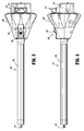
FIG. 2A is a front, perspective view of the adapter assembly of the present disclosure; -
FIG. 2B is a rear, perspective view of the adapter assembly ofFIG. 2A ; -
FIG. 3 is a top plan view of the adapter assembly ofFIGS. 2A and 2B ; -
FIG. 4 is a side, elevational view of the adapter assembly ofFIGS. 2A and 2B ; -
FIG. 5 is a rear, perspective view of the adapter assembly ofFIGS. 2A and 2B , with some parts thereof separated; -
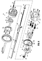
FIG. 6 is a rear, perspective view of the adapter assembly ofFIGS. 2A and 2B , with most parts thereof separated; -
FIG. 7 is a perspective view of an articulation assembly of the adapter assembly ofFIGS. 2A and 2B ; -
FIG. 8 is an enlarged, perspective view, with parts separated, of the articulation assembly ofFIG. 7 ; -
FIG. 9 is a perspective view of the articulation assembly ofFIG. 7 , shown in a first orientation; -
FIG. 10 is a perspective view of the articulation assembly ofFIG. 7 , shown in a second orientation; -
FIG. 11 is a cross-sectional view as taken along section line 11-11 ofFIG. 9 ; -
FIG. 12 is a perspective view of an electrical assembly of the adapter assembly ofFIGS. 2A and 2B ; -
FIG. 13 is a perspective view of the electrical assembly ofFIG. 12 shown connected to the core housing of the adapter assembly ofFIGS. 2A and 2B ; -
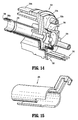
FIG. 14 is a cross-sectional view as taken along section line 14-14 ofFIG. 13 ; -
FIG. 15 is a perspective view of a slip ring cannula or sleeve of the adapter assembly ofFIGS. 2A and 2B ; -
FIG. 16 is an enlarged view of the indicated area of detail ofFIG. 2B , illustrating an inner housing assembly of the adapter assembly ofFIGS. 2A and 2B ; -
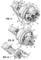
FIG. 17 is a rear, perspective view of the inner housing assembly ofFIG. 16 with an outer knob housing half-section and a proximal cap removed therefrom; -
FIG. 18 is a rear, perspective view of the inner housing assembly ofFIG. 16 with the outer knob housing, the proximal cap and a bushing plate removed therefrom; -
FIG. 19 is a rear, perspective view of the inner housing assembly ofFIG. 16 with the outer knob housing, the proximal cap, the bushing plate and an inner housing removed therefrom; -
FIG. 20 is a rear, perspective view of the an alternative embodiment of inner housing assembly similar to that shown inFIG. 16 with the outer knob housing and the proximal inner housing removed therefrom; -
FIG. 21 is a rear, perspective view of the inner housing assembly ofFIG. 20 with the outer knob housing, the proximal inner housing and the articulation assembly removed therefrom; -
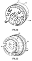
FIG. 22 is a front, perspective view of the inner housing assembly ofFIG. 20 with the outer knob housing, the proximal inner housing and the articulation assembly removed therefrom; -
FIG. 23 is a front, perspective view of the inner housing assembly ofFIG. 20 with the outer knob housing and the proximal inner housing removed therefrom; -
FIG. 24 is a cross-sectional view as taken along section line 24-24 ofFIG. 2B ; -
FIG. 25 is an enlarged view of the indicated area of detail ofFIG. 24 ; -
FIG. 26 is an enlarged view of the indicated area of detail ofFIG. 24 , illustrating a lock button being actuated in a proximal direction; -
FIG. 27 is a cross-sectional view as taken along section line 27-27 ofFIG. 2B ; -
FIG. 28 is a cross-sectional view as taken along section line 27-27 ofFIG. 2B , illustrating actuation of the articulation assembly in a distal direction; -
FIG. 29 is a cross-sectional view as taken along section line 29-29 ofFIG. 28 ; -
FIG. 30 is a cross-sectional view as taken along section line 30-30 ofFIG. 28 ; -
FIG. 31 is a cross-sectional view as taken along section line 31-31 ofFIG. 28 ; -
FIG. 32 is a rear, perspective view of a proximal inner housing hub according to the present disclosure; -
FIG. 33 is a front, perspective view of the proximal inner housing hub ofFIG. 32 ; -
FIG. 34 is a front, perspective view of the proximal inner housing hub ofFIGS. 32 and 33 illustrating a first and a second force/rotation transmitting/converting assembly and a reinforcing assembly associated therewith; -
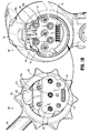
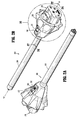
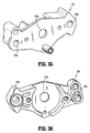
FIG. 35 is a front, perspective view of a plate bushing of the proximal inner housing assembly of the present disclosure; -
FIG. 36 is a rear, perspective view of the plate bushing ofFIG. 35 ; -
FIG. 37 is a rear, perspective view of the proximal inner housing assembly illustrating the plate bushing ofFIGS. 35 and 36 attached thereto; -
FIG. 38 is a rear, perspective view of the proximal inner housing assembly ofFIG. 37 with connector sleeves removed therefrom; -
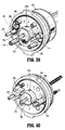
FIG. 39 is a rear, perspective view of the proximal inner housing assembly ofFIG. 37 with connector sleeves removed therefrom and the plate bushing shown in phantom; -
FIG. 40 is a rear, perspective view of the proximal inner housing assembly ofFIG. 37 with connector sleeves removed therefrom; -
FIG. 41 is a rear, perspective of the inner housing assembly ofFIG. 37 illustrating a support plate, according to another embodiment of the present disclosure, coupled thereto; -
FIG. 42 is a rear, perspective of the inner housing assembly ofFIG. 41 with the support plate removed therefrom; -
FIG. 43 is a front, perspective view of an inner housing assembly according to another embodiment of the present disclosure with the outer knob housing, the proximal inner housing removed therefrom; -
FIG. 44 is a rear, perspective view of the inner housing assembly ofFIG. 43 with the outer knob housing, the proximal inner housing and the articulation assembly removed therefrom; -
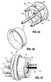
FIG. 45 is a perspective view of a bracket assembly of the inner housing assembly ofFIGS. 43 and 44 ; -
FIG. 46 is a perspective view of a reinforcing sleeve for use with the inner housing assembly ofFIGS. 43 and 44 ; -
FIG. 47 is a perspective view of the inner housing assembly ofFIGS. 43 and 44 , illustrating the reinforcing sleeve ofFIG. 46 supported thereon; -
FIG. 48 is a perspective view, with parts separated, of an exemplary loading unit for use with the surgical device and the adapter of the present disclosure; -
FIG. 49 is a perspective view of an alternative embodiment of an articulation assembly of the adapter assembly ofFIGS. 2A and 2B ; -
FIG. 50 is a perspective view of a bearing assembly of the articulation assembly ofFIG. 49 ; -
FIG. 51 is a perspective, cutaway view of the bearing assembly ofFIG. 50 , with a bearing housing removed therefrom; -
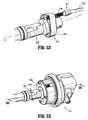
FIG. 52 is a perspective view of the bearing assembly ofFIG. 50 including a proximal drive shaft; -
FIG. 53 is a perspective view of an alternative embodiment of an inner housing assembly similar to that shown inFIG. 16 with the outer knob housing and the proximal inner housing removed therefrom; -
FIG. 54 is a perspective view of another alternative embodiment of an articulation assembly of the adapter assembly ofFIGS. 2A and 2B ; -
FIG. 55 is a perspective view of a bearing assembly of the articulation assembly ofFIG. 54 ; -
FIG. 56 is a cross-sectional view of an inner housing assembly similar to that shown inFIG. 53 taken along section line 56-56 ofFIG. 53 ; -
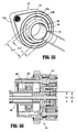
FIG. 57 is a rear perspective view of yet another alternative embodiment of a bearing assembly similar to those shown inFIGS. 50 and55 ; and -
FIG. 58 is a perspective view of still another alternative embodiment of an articulation assembly of the adapter assembly ofFIGS. 2A and 2B . - Embodiments of the presently disclosed surgical devices, adapter assemblies, and loading unit detection assemblies for surgical devices and/or handle assemblies are described in detail with reference to the drawings, in which like reference numerals designate identical or corresponding elements in each of the several views. As used herein the term "distal" refers to that portion of the adapter assembly or surgical device, or component thereof, farther from the user, while the term "proximal" refers to that portion of the adapter assembly or surgical device, or component thereof, closer to the user.
- A surgical device, in accordance with an embodiment of the present disclosure, is generally designated as 100, and is in the form of a powered hand held electromechanical instrument configured for selective attachment thereto of a plurality of different end effectors that are each configured for actuation and manipulation by the powered hand held electromechanical surgical instrument.
- As illustrated in
FIG. 1A ,surgical device 100 is configured for selective connection with anadapter assembly 200, and, in turn,adapter assembly 200 is configured for selective connection with a loading unit 300 (e.g., an end effector, multiple- or single-use loading unit, seeFIG. 48 ).Surgical device 100 andadapter assembly 200, together, may comprise an electromechanical surgical system that is configured and adapted to selectively connect with aloading unit 300 and to actuateloading unit 300. - As illustrated in
FIGS. 1A and1B ,surgical device 100 includes ahandle housing 102 including a circuit board (not shown) and a drive mechanism (not shown) is situated therein. The circuit board is configured to control the various operations ofsurgical device 100. Handlehousing 102 defines a cavity therein (not shown) for selective removable receipt of a rechargeable battery (not shown) therein. The battery is configured to supply power to any of the electrical components ofsurgical device 100. - Handle
housing 102 includes anupper housing portion 102a which houses various components ofsurgical device 100, and a lowerhand grip portion 102b extending fromupper housing portion 102a. Lowerhand grip portion 102b may be disposed distally of a proximal-most end ofupper housing portion 102a. The location oflower housing portion 102b relative toupper housing portion 102a is selected to balance a weight of asurgical device 100 that is connected to or supportingadapter assembly 200 and/orend effector 300. - Handle
housing 102 provides a housing in which the drive mechanism is situated. The drive mechanism is configured to drive shafts and/or gear components in order to perform the various operations ofsurgical device 100. In particular, the drive mechanism is configured to drive shafts and/or gear components in order to selectively move atool assembly 304 of loading unit 300 (seeFIGS. 1 and48 ) relative to aproximal body portion 302 ofloading unit 300, to rotateloading unit 300 about a longitudinal axis "X" (seeFIG. 1A ) relative to handlehousing 102, to move/approximate ananvil assembly 306 and acartridge assembly 308 ofloading unit 300 relative to one another, and/or to fire a stapling and cutting cartridge withincartridge assembly 308 ofloading unit 300. - As illustrated in
FIG. 1B , handlehousing 102 defines a connectingportion 108 configured to accept a correspondingdrive coupling assembly 210 ofadapter assembly 200. Specifically, connectingportion 108 ofsurgical device 100 has arecess 108a that receives aproximal cap 210a (FIG. 6 ) ofdrive coupling assembly 210 ofadapter assembly 200 whenadapter assembly 200 is mated tosurgical device 100. Connectingportion 108 houses three rotatable driveconnectors - When
adapter assembly 200 is mated tosurgical device 100, each ofrotatable drive connectors surgical device 100 couples with a correspondingrotatable connector sleeve adapter assembly 200. (seeFIG. 1B ). In this regard, the interface between correspondingfirst drive connector 118 andfirst connector sleeve 218, the interface between correspondingsecond drive connector 120 andsecond connector sleeve 220, and the interface between correspondingthird drive connector 122 andthird connector sleeve 222 are keyed such that rotation of each ofdrive connectors surgical device 100 causes a corresponding rotation of the correspondingconnector sleeve adapter assembly 200. - The mating of
drive connectors surgical device 100 withconnector sleeves adapter assembly 200 allows rotational forces to be independently transmitted via each of the three respective connector interfaces. Thedrive connectors surgical device 100 are configured to be independently rotated by the drive mechanism ofsurgical device 100. In this regard, a function selection module (not shown) of the drive mechanism selects which drive connector orconnectors surgical device 100 is to be driven by the motor ofsurgical device 100. - Since each of
drive connectors surgical device 100 has a keyed and/or substantially non-rotatable interface withrespective connector sleeves adapter assembly 200, whenadapter assembly 200 is coupled tosurgical device 100, rotational force(s) are selectively transferred from drive connectors ofsurgical device 100 toadapter assembly 200. - The selective rotation of drive connector(s) 118, 120 and/or 122 of
surgical device 100 allowssurgical device 100 to selectively actuate different functions ofloading unit 300. For example, selective and independent rotation offirst drive connector 118 ofsurgical device 100 corresponds to the selective and independent opening and closing oftool assembly 304 ofloading unit 300, and driving of a stapling/cutting component oftool assembly 304 ofloading unit 300. As an additional example, the selective and independent rotation ofsecond drive connector 120 ofsurgical device 100 corresponds to the selective and independent articulation oftool assembly 304 ofloading unit 300 transverse to longitudinal axis "X" (seeFIG. 1A ). Additionally, for instance, the selective and independent rotation ofthird drive connector 122 ofsurgical device 100 corresponds to the selective and independent rotation ofloading unit 300 about longitudinal axis "X" (seeFIG. 1A ) relative to handlehousing 102 ofsurgical device 100. - As illustrated in
FIG. 1A , handlehousing 102 supports a plurality of finger-actuated control buttons, rocker devices and the like for activating various functions ofsurgical device 100. - Reference may be made to International Application No.
PCT/US2008/077249, filed September 22, 2008 (Inter. Pub. No.WO 2009/039506 ) andU.S. Patent Application Serial No. 12/622,827, filed on November 20, 2009 surgical instrument 100. - Turning now to
FIGS. 1A-47 ,adapter assembly 200 includes anouter knob housing 202 and anouter tube 206 extending from a distal end ofknob housing 202.Knob housing 202 andouter tube 206 are configured and dimensioned to house the components ofadapter assembly 200.Outer tube 206 is dimensioned for endoscopic insertion, in particular, that outer tube is passable through a typical trocar port, cannula or the like.Knob housing 202 is dimensioned to not enter the trocar port, cannula of the like.Knob housing 202 is configured and adapted to connect to connectingportion 108 ofhandle housing 102 ofsurgical device 100. -
Adapter assembly 200 is configured to convert a rotation of either ofdrive connectors surgical device 100 into axial translation useful for operating adrive assembly 360 and anarticulation link 366 ofloading unit 300, as illustrated inFIG. 48 and as will be described in greater detail below. As illustrated inFIGS. 5 ,6 ,13 ,14 ,17, 18 ,20 ,25-34 and37-40 ,adapter assembly 200 includes a proximalinner housing assembly 204 rotatably supporting a first rotatableproximal drive shaft 212, a second rotatableproximal drive shaft 214, and a third rotatableproximal drive shaft 216 therein. Eachproximal drive shaft surgical device 100, as described in greater detail below. - As described briefly above,
inner housing assembly 204 ofshaft assembly 200 is also configured to rotatably support first, second andthird connector sleeves connector sleeves third drive connectors surgical device 100, as described above. Each ofconnector sleeves proximal drive shafts -
Inner housing assembly 204 also includes, as illustrated inFIGS. 6 ,17 ,27 and 28 , a first, a second and athird biasing member third connector sleeves members proximal drive shaft members respective connector sleeves connector sleeves connectors surgical device 100 whenadapter assembly 200 is connected tosurgical device 100. - In particular, first, second and
third biasing members respective connector sleeves adapter assembly 200 tosurgical device 100, if first, second and orthird connector sleeves drive connectors surgical device 100, first, second and/or third biasing member(s) 224, 226 and/or 228 are compressed. Thus, whensurgical device 100 is operated, driveconnectors surgical device 100 will rotate and first, second and/or third biasing member(s) 224, 226 and/or 228 will cause respective first, second and/or third connector sleeve(s) 218, 220 and/or 222 to slide back proximally, effectively couplingdrive connectors surgical device 100 to first, second and/or third proximal drive shaft(s) 212, 214 and 216 ofinner housing assembly 204. -
Adapter assembly 200 includes a plurality of force/rotation transmitting/converting assemblies, each disposed withininner housing assembly 204 andouter tube 206. Each force/rotation transmitting/converting assembly is configured and adapted to transmit/convert a speed/force of rotation (e.g., increase or decrease) of first, second and thirdrotatable drive connectors surgical instrument 100 before transmission of such rotational speed/force toloading unit 300. - Specifically, as illustrated in
FIG. 6 ,adapter assembly 200 includes a first, a second and a third force/rotation transmitting/convertingassembly outer tube 206. Each force/rotation transmitting/convertingassembly third drive connector surgical device 100 into axial translation ofarticulation bar 258 ofadapter assembly 200, to effectuate articulation ofloading unit 300; a rotation of aring gear 266 ofadapter assembly 200, to effectuate rotation ofadapter assembly 200; or axial translation of adistal drive member 248 ofadapter assembly 200 to effectuate closing, opening and firing ofloading unit 300. - As shown in
FIGS. 5 ,6 and24-31 , first force/rotation transmitting/convertingassembly 240 includes first rotatableproximal drive shaft 212, which, as described above, is rotatably supported withininner housing assembly 204. First rotatableproximal drive shaft 212 includes a non-circular proximal end portion configured for connection withfirst connector 218 which is connected to respectivefirst connector 118 ofsurgical device 100. First rotatableproximal drive shaft 212 includes adistal end portion 212b having a threaded outer profile or surface. - First force/rotation transmitting/converting
assembly 240 further includes adrive coupling nut 244 rotatably coupled to threadeddistal end portion 212b of first rotatableproximal drive shaft 212, and which is slidably disposed withinouter tube 206. Drivecoupling nut 244 is slidably keyed within proximal core tube portion ofouter tube 206 so as to be prevented from rotation as first rotatableproximal drive shaft 212 is rotated. In this manner, as first rotatableproximal drive shaft 212 is rotated, drivecoupling nut 244 is translated along threadeddistal end portion 212b of first rotatableproximal drive shaft 212 and, in turn, through and/or alongouter tube 206. - First force/rotation transmitting/converting
assembly 240 further includes adistal drive member 248 that is mechanically engaged withdrive coupling nut 244, such that axial movement ofdrive coupling nut 244 results in a corresponding amount of axial movement ofdistal drive member 248. The distal end portion ofdistal drive member 248 supports aconnection member 247 configured and dimensioned for selective engagement with adrive member 374 ofdrive assembly 360 of loading unit 300 (FIG. 48 ). Drivecoupling nut 244 and/ordistal drive member 248 function as a force transmitting member to components ofloading unit 300, as described in greater detail below. - In operation, as first rotatable
proximal drive shaft 212 is rotated, due to a rotation offirst connector sleeve 218, as a result of the rotation of the firstrespective drive connector 118 ofsurgical device 100, drivecoupling nut 244 is caused to be translated axially along first distal drive shaft 242. Asdrive coupling nut 244 is caused to be translated axially along first distal drive shaft 242,distal drive member 248 is caused to be translated axially relative toouter tube 206. Asdistal drive member 248 is translated axially, withconnection member 247 connected thereto and engaged withdrive member 374 ofdrive assembly 360 of loading unit 300 (FIG. 47 ),distal drive member 248 causes concomitant axial translation ofdrive member 374 ofloading unit 300 to effectuate a closure oftool assembly 304 and a firing oftool assembly 304 ofloading unit 300. - With reference to
FIGS. 5-11 ,19 and23-31 , seconddrive converter assembly 250 ofadapter assembly 200 includes secondproximal drive shaft 214 rotatably supported withininner housing assembly 204. Second rotatableproximal drive shaft 214 includes a non-circular proximal end portion configured for connection with second connector orcoupler 220 which is connected to respectivesecond connector 120 ofsurgical device 100. Second rotatableproximal drive shaft 214 further includes a distal end portion 214b having a threaded outer profile or surface. - Distal end portion 214b of
proximal drive shaft 214 is threadably engaged with anarticulation bearing housing 252a of anarticulation bearing assembly 252.Articulation bearing assembly 252 includes ahousing 252a supporting an articulation bearing 253 having aninner race 253b that is independently rotatable relative to anouter race 253a.Articulation bearing housing 252a has a non-circular outer profile, for example tear-drop shaped, that is slidably and non-rotatably disposed within acomplementary bore 204c (FIGS. 25, 26 ,29 and33 ) ofinner housing hub 204a. - Second
drive converter assembly 250 ofadapter assembly 200 further includes anarticulation bar 258 having aproximal portion 258a secured toinner race 253b of articulation bearing 253. Adistal portion 258b ofarticulation bar 258 includes aslot 258c therein, which is configured to accept aportion 366, e.g., a flag, articulation link (FIG. 47 ) ofloading unit 300.Articulation bar 258 functions as a force transmitting member to components ofloading unit 300, as described in greater detail below. - With further regard to
articulation bearing assembly 252,articulation bearing assembly 252 is both rotatable and longitudinally translatable. Additionally, it is envisioned thatarticulation bearing assembly 252 allows for free, unimpeded rotational movement ofloading unit 300 when itsjaw members jaw members - In operation, as second
proximal drive shaft 214 is rotated due to a rotation ofsecond connector sleeve 220, as a result of the rotation of thesecond drive connector 120 ofsurgical device 100,articulation bearing assembly 252 is caused to be translated axially along threaded distal end portion 214b of secondproximal drive shaft 214, which in turn causesarticulation bar 258 to be axially translated relative toouter tube 206. Asarticulation bar 258 is translated axially,articulation bar 258, being coupled to articulation link 366 ofloading unit 300, causes concomitant axial translation of articulation link 366 ofloading unit 300 to effectuate an articulation oftool assembly 304.Articulation bar 258 is secured toinner race 253b of articulation bearing 253 and is thus free to rotate about the longitudinal axis X-X relative toouter race 253a of articulation bearing 253. - As illustrated in
FIGS. 6 ,17, 18 ,20-23 ,25-28 ,31 and37-40 and as mentioned above,adapter assembly 200 includes a third force/rotation transmitting/convertingassembly 260 supported ininner housing assembly 204. Third force/rotation transmitting/convertingassembly 260 includes arotation ring gear 266 fixedly supported in and connected toouter knob housing 202.Ring gear 266 defines an internal array ofgear teeth 266a (FIG. 6 ).Ring gear 266 includes a pair of diametrically opposed, radially extendingprotrusions 266b (FIG. 6 ) projecting from an outer edge thereof.Protrusions 266b are disposed within recesses defined inouter knob housing 202, such that rotation ofring gear 266 results in rotation ofouter knob housing 202, and vice a versa. - Third force/rotation transmitting/converting
assembly 260 further includes third rotatableproximal drive shaft 216 which, as described above, is rotatably supported withininner housing assembly 204. Third rotatableproximal drive shaft 216 includes a non-circular proximal end portion configured for connection withthird connector 222 which is connected to respectivethird connector 122 ofsurgical device 100. Third rotatableproximal drive shaft 216 includes aspur gear 216a keyed to a distal end thereof. A reversingspur gear 264inter-engages spur gear 216a of third rotatableproximal drive shaft 216 to gearteeth 266a ofring gear 266. - In operation, as third rotatable
proximal drive shaft 216 is rotated, due to a rotation ofthird connector sleeve 222, as a result of the rotation of thethird drive connector 122 ofsurgical device 100,spur gear 216a of third rotatableproximal drive shaft 216 engages reversinggear 264 causing reversinggear 264 to rotate. As reversinggear 264 rotates,ring gear 266 also rotates thereby causingouter knob housing 202 to rotate. Asouter knob housing 202 is rotated,outer tube 206 is caused to be rotated about longitudinal axis "X" ofadapter assembly 200. Asouter tube 206 is rotated,loading unit 300, that is connected to a distal end portion ofadapter assembly 200, is also caused to be rotated about a longitudinal axis ofadapter assembly 200. -
Adapter assembly 200 further includes, as seen inFIGS. 1B ,3-5 ,16 ,17 ,20 and24-26 , an attachment/detachment button 272 supported thereon. Specifically,button 272 is supported ondrive coupling assembly 210 ofadapter assembly 200 and is biased by a biasingmember 274 to an un-actuated condition.Button 272 includes lip orledge 272a formed therewith that is configured to snap behind a corresponding lip orledge 108b defined alongrecess 108a of connectingportion 108 ofsurgical device 100. In use, whenadapter assembly 200 is connected tosurgical device 100,lip 272a ofbutton 272 is disposed behindlip 108b of connectingportion 108 ofsurgical device 100 to secure and retainadapter assembly 200 andsurgical device 100 with one another. In order to permit disconnection ofadapter assembly 200 andsurgical device 100 from one another,button 272 is depresses or actuated, against the bias of biasingmember 274, to disengagelip 272a ofbutton 272 andlip 108b of connectingportion 108 ofsurgical device 100. - With reference to
FIGS. 1A ,2A, 2B ,3-5 and24-26 ,adapter assembly 200 further includes alock mechanism 280 for fixing the axial position and radial orientation ofdistal drive member 248.Lock mechanism 280 includes abutton 282 slidably supported onouter knob housing 202.Lock button 282 is connected to anactuation bar 284 that extends longitudinally throughouter tube 206.Actuation bar 284 moves upon a movement oflock button 282. Upon a predetermined amount of movement oflock button 282, a distal end ofactuation bar 284 may move into contact with a lock out (not shown), which causes the lock out to cam a camming member 288 (FIG. 24 ) from arecess 249 indistal drive member 248. When cammingmember 288 is in engagement with recess 249 (e.g., at least partially withinrecess 249, seeFIGS. 6 and24 ), the engagement betweencamming member 288 anddistal drive member 248 effectively locks the axial and rotational position ofend effector 300 that is engaged withconnection member 247. - In operation, in order to lock the position and/or orientation of
distal drive member 248, a user moveslock button 282 from a distal position to a proximal position (FIGS. 25 and 26 ), thereby causing the lock out (not shown) to move proximally such that a distal face of the lock out moves out of contact withcamming member 288, which causescamming member 288 to cam intorecess 249 ofdistal drive member 248. In this manner,distal drive member 248 is prevented from distal and/or proximal movement. Whenlock button 282 is moved from the proximal position to the distal position, the distal end ofactuation bar 284 moves distally into the lock out, against the bias of a biasing member (not shown), to forcecamming member 288 out ofrecess 249, thereby allowing unimpeded axial translation and radial movement ofdistal drive member 248. - Reference may be made to
U.S. Patent Application Serial No. 13/875,571, filed on May 2, 2013 lock mechanism 280. - With reference to
FIGS. 1B ,6 ,12-15 and25-28 ,adapter assembly 200 includes anelectrical assembly 290 supported on and inouter knob housing 202 andinner housing assembly 204.Electrical assembly 290 includes a plurality of electrical contact pins 292, supported on acircuit board 294, for electrical connection to a correspondingelectrical plug 190 disposed in connectingportion 108 ofsurgical device 100.Electrical contacts 290 serve to allow for calibration and communication of life-cycle information to the circuit board ofsurgical device 100 viaelectrical plugs 190 that are electrically connected to the circuit board (not shown) ofsurgical device 100. -
Electrical assembly 290 further includes astrain gauge 296 electrically connected tocircuit board 294.Strain gauge 296 is provided with anotch 296a which is configured and adapted to receivestem 204d ofhub 204a ofinner housing assembly 204.Stem 204d ofhub 204a functions to restrict rotational movement ofstrain gauge 296. As illustrated inFIGS. 25-28 , first rotatableproximal drive shaft 212 extends throughstrain gauge 296.Strain gauge 296 provides a closed-loop feedback to a firing/clamping load exhibited by first rotatableproximal drive shaft 212. -
Electrical assembly 290 also includes aslip ring 298 disposed core tube oftube 206.Slip ring 298 is in electrical connection withcircuit board 294.Slip ring 298 functions to permit rotation of first rotatableproximal drive shaft 212 and axial translation ofdrive coupling nut 244 while still maintaining electrical contact ofelectrical contact rings 298a thereof with at least another electrical component withinadapter assembly 200, and while permitting the other electrical components to rotate about first rotatableproximal drive shaft 212 and drivecoupling nut 244 -
Electrical assembly 290 may include a slip ring cannula orsleeve 299 positioned core tube oftube 206 to protect and/or shield any wires extending fromslip ring 298. - Turning now to
FIGS. 6 ,11 ,14 ,32 and 33 ,inner housing assembly 204 has been designed to reduce incidents of racking of secondproximal drive shaft 214 asdrive shaft 214 rotates to axially translatearticulation bearing assembly 252.Inner housing assembly 204 includes ahub 204a having a distally orientedannular wall 204b defining a substantially circular outer profile, and defining a substantially tear-drop shaped inner recess or bore 204c.Bore 204c ofhub 204a is shaped and dimensioned to slidably receivearticulation bearing assembly 252 therewithin. -
Inner housing assembly 204 includes aring plate 254a (FIG. 34 ) secured to a distal face of distally orientedannular wall 204b ofhub 204a.Plate 254a defines anaperture 254e therethrough that is sized and formed therein so as to be aligned with secondproximal drive shaft 214 and to rotatably receive adistal tip 214c of secondproximal drive shaft 214. In this manner,distal tip 214c of secondproximal drive shaft 214 is supported and prevented from moving radially away from a longitudinal rotational axis of secondproximal drive shaft 214 as secondproximal drive shaft 214 is rotated to axially translatearticulation bearing assembly 252. - As illustrated in
FIGS. 14 ,32 ,39 and 40 ,hub 204a defines a feature (e.g., a stem or the like) 204d projecting therefrom which functions to engagenotch 296a ofstrain gauge 296 ofelectrical assembly 290 to measure forces experienced byshaft 212 assurgical device 100 is operated. - With reference to
FIGS. 35-40 , aplate bushing 230 ofinner housing assembly 204 is shown and described.Plate bushing 230 extends acrosshub 204a ofinner housing assembly 204 and is secured tohub 204a by fastening members.Plate bushing 230 defines threeapertures proximal drive shafts Plate bushing 230 provides a surface against which first, second andthird biasing members - While
plate bushing 230 has been shown and described as being a unitary monolithic piece, as illustrated inFIGS. 6 and37-40 , it is envisioned and within the scope of the present application thatplate bushing 230 may be separated into several parts including, and not limited to, as seen inFIGS. 40-42 , a support plate 230'extending acrossdrive shafts drive shafts hub 204a ofinner housing assembly 204. Support plate 230' may include a pair ofslots 230a', 230b' formed therein, which are configured and adapted to receivetabs 296b ofstrain gauge 296 that project axially therefrom. - Turning now to
FIGS. 43-47 , an inner housing assembly 204' according to another embodiment of the present disclosure is shown and will be described. In order to reduce incidents of racking (i.e., distal end 214b of secondproximal drive shaft 214 moving radially away from a longitudinal rotational axis thereof) of secondproximal drive shaft 214 asdrive shaft 214 rotates to axially translatearticulation bearing assembly 252, inner housing assembly 204' may include a reinforcement frame or bracket assembly 254'. Bracket assembly 254' includes afirst plate 254a' and asecond plate 254b' integrally connected to and spaced a distance fromfirst plate 254a' by a plurality of connectingrods 254c' extending therebetween. -
First plate 254a' is disposed adjacent to or in close proximity to ringgear 266 and defines anaperture 254d' therethrough.Aperture 254d' is sized and formed infirst plate 254a' so as to be aligned with secondproximal drive shaft 214 and to permit secondproximal drive shaft 214 to freely rotate therewithin.Second plate 254b' is spaced fromfirst plate 254a' so as to be disposed at a distal free end of secondproximal drive shaft 214.Second plate 254b' defines anaperture 254e' therethrough.Aperture 254e' is sized and formed in second plate orflange 254b' so as to be aligned with secondproximal drive shaft 214 and to rotatably receive adistal tip 214c of secondproximal drive shaft 214. - In this manner,
distal tip 214c of secondproximal drive shaft 214 is supported and prevented from moving radially away from a longitudinal rotational axis of secondproximal drive shaft 214 as secondproximal drive shaft 214 is rotated to axially translatearticulation bearing assembly 252. - As illustrated in
FIGS. 38 ,46 and 47 , inner housing assembly 204' may include a reinforcing sleeve 255' disposed about bracket assembly 254' to further reinforce bracket assembly 254'. It is contemplated in an embodiment that reinforcing sleeve 255' may be interposed betweenfirst plate 254a' andsecond plate 254b' of bracket assembly 254'. It is further contemplated that reinforcing sleeve 255' may be interposed betweensecond plate 254b' and a distally oriented face of proximal inner housing assembly 204'. - Turning now to
FIGS. 49-53 , a force/rotation transmitting/convertingassembly 350, according to another embodiment of the present disclosure, is shown and will be described. Force/rotation transmitting/convertingassembly 350 is similar to the second force/rotation transmitting/convertingassembly 250 and is only described herein to the extent necessary to describe the differences in construction and operation thereof. Likewise, another embodiment of an articulation bearing assembly is shown generally as 352.Articulation bearing assembly 352 is similar toarticulation bearing assembly 252 and is only described herein to the extent necessary to describe the differences in construction and operation thereof. - With reference to
FIGS. 49 and52 , force/rotation transmitting/convertingassembly 350 includes a distalforce transmitting member 354 and aproximal drive shaft 314.Proximal drive shaft 314 is rotatably supported within an inner housing assembly 312 (seeFIG. 53 ).Proximal drive shaft 314 includes adistal portion 314a having a threaded outer profile or surface and a non-circularproximal portion 314b configured for mating with arespective drive connector 120 of surgical device 100 (seeFIG. 1B ). - Distal
force transmitting member 354 includes, anarticulation bearing assembly 352, adistal articulation bar 358a, aproximal articulation bar 358b, and acollar 370.Articulation bearing assembly 352 includes a bearinghousing 352a supporting anarticulation bearing 353. In embodiments, bearinghousing 352a has a non-circular outer profile, such as, for example, a tear-drop shape. - In embodiments such as the one shown in
FIG. 57 , bearinghousing 352a includes a rackingassembly 380.Racking assembly 380 includes a first throughhole 382a and a second throughhole 382b. First and second throughholes cavity 382c in bearinghousing 352a.Cavity 382c is configured to house aball 384 having a threadedbore 384a formed therein. The threadedbore 384a ofball 384 is configured to threadably connect to the threadeddistal portion 314a of theproximal drive shaft 314. In this embodiment, bearinghousing 352a is able to or free to rack during actuation of the force/rotation transmitting/convertingassembly 350 without the stress from the racking being transferred to theproximal drive shaft 314, thereby preventing bending of theproximal drive shaft 314. - With reference momentarily to
FIG. 51 , articulation bearing 353 includes aninner race 353b that is independently rotatable relative to anouter race 353a about the longitudinal axis "X." In embodiments,outer race 353a andinner race 353b each defines a circular cross-section having an inner diameter of "D1" and "D2" respectively, wherein inner diameter "D1" is greater than "D2." - With reference back to
FIG. 49 ,distal articulation bar 358a includes abody portion 357 extending along longitudinal axis "X" between adistal end 357a and aproximal end 357b. Similarly,proximal articulation bar 358b includes abody portion 359 extending along longitudinal axis "X" between adistal end 359a and aproximal end 359b.Body portion 357 of thedistal articulation bar 358a includes an outer diameter "D3." Similarly,body portion 359 of the proximalarticular bar 358b includes an outer diameter "D4," wherein outer diameter "D3" is equal to outer diameter "D4." - In embodiments as shown in
FIG. 49 ,distal end 359a of theproximal articulation bar 358a defines a cut out 355 shaped for mating with theproximal end 357b of thedistal articulation bar 358a. This enablesdistal end 359a ofproximal articulation bar 358b to connect to theproximal end 357b of thedistal articulation bar 358a. In embodiments,distal end 359a ofproximal articulation bar 358b is welded toproximal end 357b of thedistal articulation bar 358a. However, it is envisioned that the distal and proximal articulation bars 358a, 358b may be fixedly connected using adhesives. In embodiments, cut out 355 is shaped such that there is a gap "G" between theproximal end 357b of thedistal articulation bar 358a and aproximal portion 355a of cut out 355. Gap "G" enablesdistal end 357a of thedistal articulation bar 358a to be spaced from the articulation bearing 353 with greater accuracy and repeatability within the tolerance. -
Proximal articulation bar 358b further includes atransition portion 359c extending proximally fromproximal articulation bar 358b.Transition portion 359c includes an outer diameter "D5," wherein outer diameter "D5" is greater than outer diameter "D3" and outer diameter "D4." As shown inFIG. 49 ,transition portion 359c abutscollar 370. In effect,proximal articulation bar 358b includes abody portion 359 that extends proximally to transitionportion 359c, which extends proximally tocollar 370. - As shown in
FIG. 51 ,collar 370 of distalforce transmitting member 354 includes afirst portion 370a having a first outer diameter "D6" and asecond portion 370b having a second outer diameter "D7," wherein first outer diameter "D6" is greater than second outer diameter "D7." In embodiments,second portion 370b is correspondingly sized with theinner race 353b of the articulation bearing 353 such that thesecond portion 370b ofcollar 370 engages an inner surface (not shown) ofinner race 353b of the articulation bearing 353. In these embodiments,first portion 370a ofcollar 370 is larger than theinner race 353b of the articulation bearing 353 such that only thesecond portion 370b ofcollar 370 mates with theinner race 353b of articulation bearing 353. - In some embodiments,
collar 370 is affixed to articulation bearing 353 by weldingsecond portion 370b ofcollar 370 toinner race 353b of articulation bearing 353. In embodiments, awasher 353c is welded to aproximal end 353d of the articulation bearing 353 to furthersecure collar 370 to articulation bearing 353. As shown inFIG.51 ,washer 353c has an outer diameter "D6"' equal to the first outer diameter "D6" of thefirst portion 370a ofcollar 370a.Washer 353c has an inner diameter "D8" which is greater than the second outer diameter "D7" of thesecond portion 370b ofcollar 370 such that thesecond portion 370b ofcollar 370 engages an inner surface (not shown) ofwasher 353c. It is envisioned thatwasher 353c can be secured to theproximal end 353d of the articulation bearing 353 andsecond portion 370b ofcollar 370 using adhesives or other securing means. - Continuing with
FIG. 51 , outer diameter "D5" of thetransition portion 359c and first outer diameter "D6" of thefirst portion 370a ofcollar 370 are both greater than outer diameter "D4" ofbody portion 359. In embodiments, outer diameter "D5" of thetransition portion 359c is less than outer diameter "D6" of thefirst portion 370a ofcollar 370. However, in alternate embodiments, outer diameter "D5" may be equal to outer diameter "D6." In operation, the larger outer diameter "D6" of thefirst portion 370a ofcollar 370 enablesproximal articulation bar 358b to resist bending as the force/rotation transmitting/convertingassembly 350 converts and transmits a rotation of theproximal drive shaft 314 to an axial translation of the loading unit 300 (FIG. 48 ). This relationship is determined by the equation:
- With reference to
FIG. 53 , force/rotation transmitting/convertingassembly 350 further includes anarticulation plate 354a configured to secure the distalforce transmitting member 354 within theinner housing assembly 312.Articulation plate 354a defines a throughhole 354b having a diameter "D9" configured for locating and supporting thefirst portion 370a ofcollar 370. The diameter "D9" of the throughhole 354b of thearticulation plate 354a is greater than the first outer diameter "D6" of thefirst portion 370a of thecollar 370 such that the mating ofarticulation plate 354a andcollar 370 reinforcescollar 370 to resist bending of theproximal articulation bar 358b. - Turning now to
FIGS. 54-56 , a force/rotation transmitting/convertingassembly 450, according to another embodiment of the present disclosure, is shown and will be described. Force/rotation transmitting/convertingassembly 450 is similar to the second force/rotation transmitting/convertingassembly Articulation bearing assembly 452 is similar toarticulation bearing assembly - With reference to
FIGS. 55 , distalforce transmitting member 454 includes, anarticulation bearing assembly 452, anarticulation bar 458, and aninner sleeve 460.Articulation bearing assembly 452 includes a bearinghousing 452a supporting anarticulation bearing 453.Articulation bearing 453 includes aninner race 453b that is independently rotatable relative to anouter race 453a.Outer race 453a andinner race 453b each defines a circular cross-section. - In some embodiments, bearing
housing 452a has a non-circular outer profile, such as, for example, a tear-drop shape. In embodiments, the bearinghousing 452a includes a racking assembly 380 (FIG. 57 ) similar to the one described above with reference to bearinghousing 352a. In this embodiment, rackingassembly 380 enables bearinghousing 452a to rack during actuation of the force/rotation transmitting/convertingassembly 450 without the stress from the racking being transferred to theproximal drive shaft 414, thereby preventing bending of theproximal drive shaft 414. -
Articulation bar 458 extends along longitudinal axis "X" between adistal portion 459a and aproximal portion 459b.Distal portion 459a of thearticulation bar 458 is configured to connect to articulation link 366 (FIG. 48 ) ofloading unit 300. As will be discussed in greater detail below,proximal portion 459b of thearticulation bar 458 is disposed between theinner race 453b of the articulation bearing 453 and theinner sleeve 460. -
Inner sleeve 460 extends axially beyond the articulation bearing 453. For example, the articulation bearing 453 may define a length "L1," andinner sleeve 460 may define a length "L2," wherein length "L1" is less than length "L2." It is envisioned that the longer aspect ratio of theinner sleeve 460 relative to the articulation bearing 453 will reduce bending of thearticulation bar 458 as it rotates about the longitudinal axis "X" relative to the articulation bearing 453. Though the figures showinner sleeve 460 extending distally from articulation bearing 453, it is envisioned thatinner sleeve 460 may also extend proximally from articulation bearing 453. - As shown in
FIG. 55 ,inner sleeve 460 is supported withininner race 453b of articulation bearing 453. Accordingly,inner race 453b defines an inner diameter "D10" andinner sleeve 460 defines an outer diameter "D11," wherein inner diameter "D10" is greater than outer diameter "D11" such that an outer surface 460a ofinner sleeve 460 abuts an inner surface (not shown) ofinner race 453b. - In embodiments, the outer surface 460a of
inner sleeve 460 defines aslot 470 shaped for disposal of theproximal portion 459b of thearticulation bar 458, e.g.,proximal portion 459b of thearticulation bar 458 is disposed inslot 470 betweeninner sleeve 460 andinner race 453b. To secure theproximal portion 459b of thearticulation bar 458 to the articulation bearing 453, theproximal portion 459b of thearticulation bar 458 is welded into theslot 470. However, in embodiments, any appropriate means, such as for example, adhesives may be used to secure thearticulation bar 458 to the articulation bearing 453. In embodiments, there may be a gap (not shown) between theproximal portion 459b of thearticulation bar 458 and a proximal face (not shown) of theslot 470 on the outer surface 460a of theinner sleeve 460. It is envisioned that the gap would enable a manufacturer to space thearticulation bar 458 in relation to the articulation bearing 453 with greater accuracy and repeatability. - With reference to
FIG. 56 , aninner housing assembly 412, similar toinner housing assembly 312, is shown.Inner housing assembly 412 includes an electrical assembly 490 similar toelectrical assembly 290. The electrical assembly 490 includes aslip ring cannula 499 supported withininner sleeve 460 to protect and/or shield any wires extending throughslip ring cannula 499.Slip ring cannula 499 has an outer diameter "D12" which is less than an inner diameter "D13" of theinner sleeve 460 such that theslip ring cannula 499 engages theinner sleeve 460 utilizing an interference fit. - Turning now to
FIG. 58 , a force/rotation transmitting/convertingassembly 550 according to another embodiment of the present disclosure is shown and will be described. Force/rotation transmitting/convertingassembly 550 is similar to the second force/rotation transmitting/convertingassembly - Force/rotation transmitting/converting
assembly 550 includes a proximal rotation receiving member, such as, for example, aproximal drive shaft 514 engagable with a respective rotatable drive shaft (not shown) of thesurgical device 100, adriver 560, and a distalforce transmitting member 554. Theproximal drive shaft 514 extends along longitudinal axis "X" between adistal portion 514a and aproximal portion 514b. Theproximal drive shaft 514 member includes anouter surface 514c defining a plurality ofspur gears 514d extending along the longitudinal axis "X." - The
driver 560 extends along longitudinal axis "X" between a distal portion and 560a and aproximal portion 560b. Thedriver 560 includes anouter surface 560c defining a plurality ofspur gears 560d extending along the longitudinal axis "X" where the plurality ofspur gears 560d of thedriver 560 are configured to engage the plurality ofspur gears 514d of theproximal drive shaft 514. Accordingly, when theproximal drive shaft 514 is rotated relative to thedriver 560 about the longitudinal axis "X" in a direction given by arrow "A," thedriver 560 is rotated in the opposite direction relative to theproximal drive shaft 514 about the longitudinal axis "X" given by arrow "B." - With continued reference to
FIG. 58 ,driver 560 includes aninner surface 560e defining abore 562 therethrough. Thebore 562 defines a plurality ofthreads 562a.Distal portion 560a of thedriver 560 defines a protrusion, such as, for example, adistal boss 564. Similarly,proximal portion 560b of thedriver 560 defines a protrusion, such as, for example, aproximal boss 566. - An inner housing assembly (not shown) similar to
inner housing assembly distal articulation plate 556 defining a first through hole 556a configured for locating thedistal boss 564 of thedriver 560. Whendistal boss 564 is mounted into the first through hole 556a of thedistal articulation plate 556, thedriver 560 is co-axial to the longitudinal axis "X."Distal articulation plate 556 also includes a second throughhole 556b configured for locating and supporting adistal protrusion 516 extending from thedistal portion 514a of theproximal drive shaft 514. - When the
distal boss 564 of thedriver 560 is located in the first through hole 556a and thedistal protrusion 516 of theproximal drive shaft 514 is located in the second throughhole 556b, the plurality ofspur gears 560d of thedriver 560 are engageable with the plurality ofspur gears 514d of theproximal drive shaft 514. The housing (not shown) also includes aproximal core portion 520 configured for locating theproximal boss 566 of thedriver 560. Theproximal core portion 520 includes a throughhole 520a configured to locate theproximal boss 566 of thedriver 560 such that thedriver 560 is co-axial to longitudinal axis "X." - Continuing with reference to
FIG. 58 , the distalforce transmitting member 554 includes asleeve 552 and anarticulation bar 558.Sleeve 552 includes anouter surface 552a defining a plurality ofthreads 552b configured to engage with the plurality ofthreads 562a defined in thebore 562 of thedriver 560.Sleeve 552 also includes aninner surface 552c defining abore 553 therethrough.Articulation bar 558 extends along longitudinal axis "X" between adistal portion 559a and aproximal portion 559b. Theproximal portion 559b of the articulation bar is secured to theinner surface 552c of thesleeve 552 such that when the sleeve is threadingly connected to thedriver 560, thearticulation bar 558 is co-axial to longitudinal axis "X." - In operation, as the
proximal drive shaft 514 is rotated about the longitudinal axis "X" in the direction given by arrow "A," the plurality ofspur gears 514d engages the plurality ofspur gears 560d of thedriver 560 to rotatedriver 560 about the longitudinal axis "X" in the direction given by arrow "B." Asdriver 560 rotates, thesleeve 552 of the distalforce transmitting member 554 is axially translated, resulting in axial translation of theloading unit 300 ofsurgical device 100. - In accordance with the present disclosure, an overall length of
adapter assembly 200 has been reduced as compared to prior adapter assemblies that have been developed to transmit/convert forces/rotations fromsurgical device 100 toloading unit 300. By reducing an overall length ofadapter assembly 200, a center of gravity of an assembledsurgical device 100,adapter assembly 200 andloading unit 300 has been shifted proximally as compared to a center of gravity of an assembledsurgical device 100, a prior adapter assembly and aloading unit 300. As such, a level of comfort to the end user in using the electromechanical surgical system of the present disclosure has been increased, and a level of fatigue has been decreased. - In operation, when a button of
surgical device 100 is activated by the user, the software checks predefined conditions. If conditions are met, the software controls the motors and delivers mechanical drive to the attached surgical stapler, which can then open, close, rotate, articulate or fire depending on the function of the pressed button. The software also provides feedback to the user by turning colored lights on or off in a defined manner to indicate the status ofsurgical device 100,adapter assembly 200 and/orloading unit 300. - Reference may be made to
U.S. Patent Publication No. 2009/0314821, filed on August 31, 2009 , the entire contents of each of which are incorporated herein by reference, for a detailed discussion of the construction and operation ofloading unit 300, as illustrated inFIGS. 1 and48 . - Any of the components described herein may be fabricated from either metals, plastics, resins, composites or the like taking into consideration strength, durability, wearability, weight, resistance to corrosion, ease of manufacturing, cost of manufacturing, and the like.
- It will be understood that various modifications may be made to the embodiments of the presently disclosed adapter assemblies. Therefore, the above description should not be construed as limiting, but merely as exemplifications of embodiments. Those skilled in the art will envision other modifications within the scope and spirit of the present disclosure.
- The invention may be described by reference to the following numbered paragraphs:-
- 1. An adapter assembly for selectively interconnecting a surgical loading unit that is configured to perform a function and a surgical device that is configured to actuate the loading unit, the loading unit including an axially translatable drive member, and the surgical device including at least one rotatable drive shaft, the adapter assembly comprising:
- a housing configured for connection with the surgical device and configured to be in operative communication with each rotatable drive shaft of the surgical device;
- an outer tube having a proximal end supported by the housing and a distal end configured for connection with the loading unit, wherein the distal end of the outer tube is in operative communication with each of the at least one axially translatable drive member of the loading unit; and
- a force/rotation transmitting/converting assembly for interconnecting a respective drive shaft of the surgical device and a respective axially translatable drive member of the loading unit, wherein the force/rotation transmitting/converting assembly includes:
- a proximal rotation receiving member that is connectable to the respective drive shaft of the surgical device defining a threaded distal end; and
- a distal force transmitting member that is connectable to an articulation link of the axially translatable drive member of the loading unit, the distal force transmitting member including:
- a bearing assembly having an outer race threadably connected to the threaded distal end of the proximal drive shaft and an inner race;
- a distal articulation bar having a proximal end and a distal end, the distal end of the distal articulation bar being configured to selectively engage the axially translatable drive member of the loading unit;
- a proximal articulation bar having a proximal end and a distal end, the distal end of the proximal articulation bar being secured to the proximal end of the distal articulation bar; and
- a collar integrally supported at the proximal end of the proximal articulation bar, the collar having an outer diameter substantially equal to an outer diameter of the inner race of the bearing assembly;
- 2. The adapter assembly according to paragraph 1, wherein the proximal articulation bar includes a transition portion integrally supporting the collar at a proximal end thereof and a body portion at a distal end thereof, the transition portion defining an outer diameter that is greater than an outer diameter of the body portion.
- 3. The adapter assembly according to
paragraph 2, wherein the outer diameter of the collar is greater than the outer diameter of the transition portion such that the distal articulation bar and the proximal articulation bar resist bending during use. - 4. The adapter assembly according to paragraph 1, wherein the distal end of the proximal articulation bar defines a cut-out configured for mating with the proximal end of the distal articulation bar.
- 5. The adapter assembly according to paragraph 1, wherein the outer race of the bearing assembly includes a first through hole and a second through hole, the first and second through holes intersecting to define a cavity in the outer race configured for housing a ball having a threaded bore formed therein, the threaded bore configured for threadably connecting to the threaded distal end of the proximal drive shaft.
- 6. An adapter assembly for selectively interconnecting a surgical loading unit that is configured to perform a function and a surgical device that is configured to actuate the loading unit, the loading unit including an axially translatable drive member, and the surgical device including at least one rotatable drive shaft, the adapter assembly comprising:
- a housing configured for connection with the surgical device and configured to be in operative communication with each rotatable drive shaft of the surgical device;
- an outer tube having a proximal end supported by the housing and a distal end configured for connection with the loading unit, wherein the distal end of the outer tube is in operative communication with each of the at least one axially translatable drive member of the loading unit; and
- a force/rotation transmitting/converting assembly for interconnecting a respective drive shaft of the surgical device and a respective axially translatable drive member of the loading unit, wherein the force/rotation transmitting/converting assembly includes:
- a proximal rotation receiving member that is connectable to a respective rotatable drive shaft of the surgical device, the proximal rotation receiving member defining a threaded distal end; and
- a distal force transmitting member that is connectable to an articulation link of the axially translatable drive member of the loading unit, the distal force transmitting member including:
- an articulation bar extending longitudinally between a proximal end and a distal end, the distal end of the articulation bar being configured to selectively engage the axially translatable drive member of the loading unit;
- a bearing assembly having an outer race threadably connected to the threaded distal end of the proximal drive shaft, and an inner race; and
- an inner sleeve supported in the inner race of the bearing assembly and extending axially from the inner race, the inner sleeve including an inner diameter and an outer diameter, the outer diameter defining a slot configured for disposal of the proximal end of the articulation bar such that the proximal end of the articulation bar is disposed between the inner race of the bearing assembly and the outer diameter of the inner sleeve;
- 7. The adapter assembly according to paragraph 6, wherein the articulation bar includes an inner diameter that is greater than the inner diameter of the inner sleeve.
- 8. The adapter assembly according to paragraph 7, wherein the housing includes a slip ring cannula disposed within the inner sleeve such that an outer diameter of the slip ring cannula engages the inner diameter of the inner sleeve utilizing an interference fit.
- 9. The adapter assembly according to paragraph 6, wherein the outer race of the bearing assembly includes a first through hole and a second through hole, the first and second through holes intersecting to define a cavity in the outer race configured for housing a ball having a threaded bore formed therein, the threaded bore configured for threadably connecting to the threaded distal end of the proximal drive shaft.
- 10. An adapter assembly for selectively interconnecting a surgical loading unit that is configured to perform a function and a surgical device that is configured to actuate the loading unit, the loading unit including an axially translatable drive member, and the surgical device including at least one rotatable drive shaft, the adapter assembly comprising:
- a housing configured for connection with the surgical device and configured to be in operative communication with each rotatable drive shaft of the surgical device;
- an outer tube defining a longitudinal axis, the outer tube having a proximal end supported by the housing and a distal end configured for connection with the loading unit, wherein the distal end of the outer tube is in operative communication with each of the at least one axially translatable drive member of the loading unit; and
- a force/rotation transmitting/converting assembly for interconnecting a respective drive shaft of the surgical device and a respective axially translatable drive member of the loading unit, wherein the at least one force/rotation transmitting/converting assembly includes:
- a proximal rotation receiving member that is connectable to a respective rotatable drive shaft of the surgical device, the proximal rotation receiving member defining at least one spur gear;
- a driver including an outer surface defining at least one spur gear configured for mating with the spur gear of the proximal rotation receiving member, the driver defining a bore therethrough, the bore having an inner surface defining at least one thread; and
- a distal force transmitting member that is connectable to an articulation link of the axially translatable drive member of the loading unit, the distal force transmitting member including:
- a sleeve having an outer surface defining at least one thread configured to mate with the inner surface of the driver; and
- an articulation bar having a proximal end secured to the sleeve and a distal end configured to selectively engage the axially translatable drive member of the loading unit;
- 11. The adapter assembly according to
paragraph 10, wherein the housing includes a distal plate having a first through hole configured for locating a distal boss of the driver such that the driver is mounted co-axial to the longitudinal axis. - 12. The adapter assembly according to
paragraph 11, wherein the distal plate includes a second through hole configured for locating a distal protrusion of the proximal rotation receiving member such that when the distal boss of the driver is located in the first through hole and the distal protrusion of the proximal rotation receiving member is located in the second through hole, the at least one spur gear of the driver is mated with the at least one spur gear of the proximal rotation receiving member. - 13. The adapter assembly according to paragraph 12, wherein the housing defines a proximal core portion configured for location a proximal boss of the driver such that the driver is mounted co-axial to the longitudinal axis.
- 14. The adapter assembly according to
paragraph 10, wherein the sleeve defines a bore therethrough which defines an inner surface, and wherein the proximal end of the articulation bar is secured to the inner surface of the sleeve.
Claims (14)
- An adapter assembly for selectively interconnecting a surgical loading unit that is configured to perform a function and a surgical device that is configured to actuate the loading unit, the loading unit including an axially translatable drive member, and the surgical device including at least one rotatable drive shaft, the adapter assembly comprising:a housing configured for connection with the surgical device and configured to be in operative communication with each rotatable drive shaft of the surgical device;an outer tube having a proximal end supported by the housing and a distal end configured for connection with the loading unit, wherein the distal end of the outer tube is in operative communication with each of the at least one axially translatable drive member of the loading unit; anda force/rotation transmitting/converting assembly for interconnecting a respective drive shaft of the surgical device and a respective axially translatable drive member of the loading unit, wherein the force/rotation transmitting/converting assembly includes:wherein the force/rotation transmitting/converting assembly converts and transmits a rotation of the rotatable drive shaft of the surgical device to an axial translation of the axially translatable drive member of the loading unit.a proximal rotation receiving member that is connectable to the respective drive shaft of the surgical device defining a threaded distal end; anda distal force transmitting member that is connectable to an articulation link of the axially translatable drive member of the loading unit, the distal force transmitting member including:a bearing assembly having an outer race threadably connected to the threaded distal end of the proximal drive shaft and an inner race;a distal articulation bar having a proximal end and a distal end, the distal end of the distal articulation bar being configured to selectively engage the axially translatable drive member of the loading unit;a proximal articulation bar having a proximal end and a distal end, the distal end of the proximal articulation bar being secured to the proximal end of the distal articulation bar; anda collar integrally supported at the proximal end of the proximal articulation bar, the collar having an outer diameter substantially equal to an outer diameter of the inner race of the bearing assembly;
- The adapter assembly according to claim 1, wherein the proximal articulation bar includes a transition portion integrally supporting the collar at a proximal end thereof and a body portion at a distal end thereof, the transition portion defining an outer diameter that is greater than an outer diameter of the body portion.
- The adapter assembly according to claim 2, wherein the outer diameter of the collar is greater than the outer diameter of the transition portion such that the distal articulation bar and the proximal articulation bar resist bending during use.
- The adapter assembly according to any preceding claim, wherein the distal end of the proximal articulation bar defines a cut-out configured for mating with the proximal end of the distal articulation bar.
- The adapter assembly according to any preceding claim, wherein the outer race of the bearing assembly includes a first through hole and a second through hole, the first and second through holes intersecting to define a cavity in the outer race configured for housing a ball having a threaded bore formed therein, the threaded bore configured for threadably connecting to the threaded distal end of the proximal drive shaft.
- An adapter assembly for selectively interconnecting a surgical loading unit that is configured to perform a function and a surgical device that is configured to actuate the loading unit, the loading unit including an axially translatable drive member, and the surgical device including at least one rotatable drive shaft, the adapter assembly comprising:a housing configured for connection with the surgical device and configured to be in operative communication with each rotatable drive shaft of the surgical device;an outer tube having a proximal end supported by the housing and a distal end configured for connection with the loading unit, wherein the distal end of the outer tube is in operative communication with each of the at least one axially translatable drive member of the loading unit; anda force/rotation transmitting/converting assembly for interconnecting a respective drive shaft of the surgical device and a respective axially translatable drive member of the loading unit, wherein the force/rotation transmitting/converting assembly includes:wherein the force/rotation transmitting/converting assembly converts and transmits a rotation of the rotatable drive shaft of the surgical device to an axial translation of the axially translatable drive member of the loading unit.a proximal rotation receiving member that is connectable to a respective rotatable drive shaft of the surgical device, the proximal rotation receiving member defining a threaded distal end; anda distal force transmitting member that is connectable to an articulation link of the axially translatable drive member of the loading unit, the distal force transmitting member including:an articulation bar extending longitudinally between a proximal end and a distal end, the distal end of the articulation bar being configured to selectively engage the axially translatable drive member of the loading unit;a bearing assembly having an outer race threadably connected to the threaded distal end of the proximal drive shaft, and an inner race; andan inner sleeve supported in the inner race of the bearing assembly and extending axially from the inner race, the inner sleeve including an inner diameter and an outer diameter, the outer diameter defining a slot configured for disposal of the proximal end of the articulation bar such that the proximal end of the articulation bar is disposed between the inner race of the bearing assembly and the outer diameter of the inner sleeve;
- The adapter assembly according to claim 6, wherein the articulation bar includes an inner diameter that is greater than the inner diameter of the inner sleeve.
- The adapter assembly according to claim 7, wherein the housing includes a slip ring cannula disposed within the inner sleeve such that an outer diameter of the slip ring cannula engages the inner diameter of the inner sleeve utilizing an interference fit.
- The adapter assembly according to any of claims 6 to 8, wherein the outer race of the bearing assembly includes a first through hole and a second through hole, the first and second through holes intersecting to define a cavity in the outer race configured for housing a ball having a threaded bore formed therein, the threaded bore configured for threadably connecting to the threaded distal end of the proximal drive shaft.
- An adapter assembly for selectively interconnecting a surgical loading unit that is configured to perform a function and a surgical device that is configured to actuate the loading unit, the loading unit including an axially translatable drive member, and the surgical device including at least one rotatable drive shaft, the adapter assembly comprising:a housing configured for connection with the surgical device and configured to be in operative communication with each rotatable drive shaft of the surgical device;an outer tube defining a longitudinal axis, the outer tube having a proximal end supported by the housing and a distal end configured for connection with the loading unit, wherein the distal end of the outer tube is in operative communication with each of the at least one axially translatable drive member of the loading unit; anda force/rotation transmitting/converting assembly for interconnecting a respective drive shaft of the surgical device and a respective axially translatable drive member of the loading unit, wherein the at least one force/rotation transmitting/converting assembly includes:wherein the force/rotation transmitting/converting assembly converts and transmits a rotation of the rotatable drive shaft of the surgical device to a rotation of the driver such that the sleeve of the distal force transmitting member is axially translated resulting in an axial translation of the axially translatable drive member of the loading unit.a proximal rotation receiving member that is connectable to a respective rotatable drive shaft of the surgical device, the proximal rotation receiving member defining at least one spur gear;a driver including an outer surface defining at least one spur gear configured for mating with the spur gear of the proximal rotation receiving member, the driver defining a bore therethrough, the bore having an inner surface defining at least one thread; anda distal force transmitting member that is connectable to an articulation link of the axially translatable drive member of the loading unit, the distal force transmitting member including:a sleeve having an outer surface defining at least one thread configured to mate with the inner surface of the driver; andan articulation bar having a proximal end secured to the sleeve and a distal end configured to selectively engage the axially translatable drive member of the loading unit;
- The adapter assembly according to claim 10, wherein the housing includes a distal plate having a first through hole configured for locating a distal boss of the driver such that the driver is mounted co-axial to the longitudinal axis.
- The adapter assembly according to claim 11, wherein the distal plate includes a second through hole configured for locating a distal protrusion of the proximal rotation receiving member such that when the distal boss of the driver is located in the first through hole and the distal protrusion of the proximal rotation receiving member is located in the second through hole, the at least one spur gear of the driver is mated with the at least one spur gear of the proximal rotation receiving member.
- The adapter assembly according to any of claims 10 to 12, wherein the housing defines a proximal core portion configured for location a proximal boss of the driver such that the driver is mounted co-axial to the longitudinal axis.
- The adapter assembly according to any of claims 10 to 13, wherein the sleeve defines a bore therethrough which defines an inner surface, and wherein the proximal end of the articulation bar is secured to the inner surface of the sleeve.
Applications Claiming Priority (1)
| Application Number | Priority Date | Filing Date | Title |
|---|---|---|---|
| US14/822,970 US10123799B2 (en) | 2013-12-09 | 2015-08-11 | Adapter assembly for interconnecting electromechanical surgical devices and surgical loading units, and surgical systems thereof |
Publications (3)
| Publication Number | Publication Date |
|---|---|
| EP3130293A2 true EP3130293A2 (en) | 2017-02-15 |
| EP3130293A3 EP3130293A3 (en) | 2017-05-31 |
| EP3130293B1 EP3130293B1 (en) | 2019-11-06 |
Family
ID=56618062
Family Applications (1)
| Application Number | Title | Priority Date | Filing Date |
|---|---|---|---|
| EP16183520.2A Active EP3130293B1 (en) | 2015-08-11 | 2016-08-10 | Adapter assembly for interconnecting electromechanical surgical devices and surgical loading units, and surgical systems thereof |
Country Status (2)
| Country | Link |
|---|---|
| EP (1) | EP3130293B1 (en) |
| CN (1) | CN106419984B (en) |
Cited By (2)
| Publication number | Priority date | Publication date | Assignee | Title |
|---|---|---|---|---|
| EP3718486A1 (en) * | 2019-04-05 | 2020-10-07 | Covidien LP | Adapter assembly including a drive belt |
| CN112932578A (en) * | 2019-11-26 | 2021-06-11 | 柯惠Lp公司 | Surgical instrument including adapter assembly and articulating surgical loading unit |
Family Cites Families (11)
| Publication number | Priority date | Publication date | Assignee | Title |
|---|---|---|---|---|
| US9055943B2 (en) * | 2007-09-21 | 2015-06-16 | Covidien Lp | Hand held surgical handle assembly, surgical adapters for use between surgical handle assembly and surgical end effectors, and methods of use |
| US8806973B2 (en) * | 2009-12-02 | 2014-08-19 | Covidien Lp | Adapters for use between surgical handle assembly and surgical end effector |
| US8021366B2 (en) * | 2005-07-11 | 2011-09-20 | Kyphon Sarl | Axial load limiting system and methods |
| US8800837B2 (en) * | 2007-04-13 | 2014-08-12 | Covidien Lp | Powered surgical instrument |
| US9023014B2 (en) * | 2007-09-21 | 2015-05-05 | Covidien Lp | Quick connect assembly for use between surgical handle assembly and surgical accessories |
| US8292150B2 (en) * | 2010-11-02 | 2012-10-23 | Tyco Healthcare Group Lp | Adapter for powered surgical devices |
| US9050125B2 (en) * | 2011-10-10 | 2015-06-09 | Ethicon Endo-Surgery, Inc. | Ultrasonic surgical instrument with modular end effector |
| DE102012200073A1 (en) * | 2012-01-04 | 2013-07-04 | Karl Storz Gmbh & Co. Kg | Medical instrument |
| US10478182B2 (en) * | 2012-10-18 | 2019-11-19 | Covidien Lp | Surgical device identification |
| US9629633B2 (en) * | 2013-07-09 | 2017-04-25 | Covidien Lp | Surgical device, surgical adapters for use between surgical handle assembly and surgical loading units, and methods of use |
| US9918713B2 (en) * | 2013-12-09 | 2018-03-20 | Covidien Lp | Adapter assembly for interconnecting electromechanical surgical devices and surgical loading units, and surgical systems thereof |
-
2016
- 2016-08-09 CN CN201610647902.3A patent/CN106419984B/en active Active
- 2016-08-10 EP EP16183520.2A patent/EP3130293B1/en active Active
Non-Patent Citations (1)
| Title |
|---|
| None |
Cited By (5)
| Publication number | Priority date | Publication date | Assignee | Title |
|---|---|---|---|---|
| EP3718486A1 (en) * | 2019-04-05 | 2020-10-07 | Covidien LP | Adapter assembly including a drive belt |
| CN111839632A (en) * | 2019-04-05 | 2020-10-30 | 柯惠Lp公司 | Surgical instrument including adapter assembly and articulating surgical loading unit |
| US11241228B2 (en) | 2019-04-05 | 2022-02-08 | Covidien Lp | Surgical instrument including an adapter assembly and an articulating surgical loading unit |
| US11925348B2 (en) | 2019-04-05 | 2024-03-12 | Covidien Lp | Surgical instrument including an adapter assembly and an articulating surgical loading unit |
| CN112932578A (en) * | 2019-11-26 | 2021-06-11 | 柯惠Lp公司 | Surgical instrument including adapter assembly and articulating surgical loading unit |
Also Published As
| Publication number | Publication date |
|---|---|
| EP3130293A3 (en) | 2017-05-31 |
| CN106419984B (en) | 2021-03-05 |
| EP3130293B1 (en) | 2019-11-06 |
| CN106419984A (en) | 2017-02-22 |
Similar Documents
| Publication | Publication Date | Title |
|---|---|---|
| AU2019201734B2 (en) | Adapter assembly for interconnecting electromechanical surgical devices and surgical loading units, and surgical systems thereof | |
| US20220175376A1 (en) | Adapter assembly for interconnecting electromechanical surgical devices and surgical loading units, and surgical systems thereof | |
| US10772631B2 (en) | Adapter assembly for interconnecting electromechanical surgical devices and surgical loading units, and surgical systems thereof | |
| EP3130293B1 (en) | Adapter assembly for interconnecting electromechanical surgical devices and surgical loading units, and surgical systems thereof |
Legal Events
| Date | Code | Title | Description |
|---|---|---|---|
| PUAI | Public reference made under article 153(3) epc to a published international application that has entered the european phase |
Free format text: ORIGINAL CODE: 0009012 |
|
| STAA | Information on the status of an ep patent application or granted ep patent |
Free format text: STATUS: THE APPLICATION HAS BEEN PUBLISHED |
|
| AK | Designated contracting states |
Kind code of ref document: A2 Designated state(s): AL AT BE BG CH CY CZ DE DK EE ES FI FR GB GR HR HU IE IS IT LI LT LU LV MC MK MT NL NO PL PT RO RS SE SI SK SM TR |
|
| AX | Request for extension of the european patent |
Extension state: BA ME |
|
| PUAL | Search report despatched |
Free format text: ORIGINAL CODE: 0009013 |
|
| AK | Designated contracting states |
Kind code of ref document: A3 Designated state(s): AL AT BE BG CH CY CZ DE DK EE ES FI FR GB GR HR HU IE IS IT LI LT LU LV MC MK MT NL NO PL PT RO RS SE SI SK SM TR |
|
| AX | Request for extension of the european patent |
Extension state: BA ME |
|
| RIC1 | Information provided on ipc code assigned before grant |
Ipc: A61B 17/072 20060101AFI20170425BHEP |
|
| STAA | Information on the status of an ep patent application or granted ep patent |
Free format text: STATUS: REQUEST FOR EXAMINATION WAS MADE |
|
| 17P | Request for examination filed |
Effective date: 20171128 |
|
| RBV | Designated contracting states (corrected) |
Designated state(s): AL AT BE BG CH CY CZ DE DK EE ES FI FR GB GR HR HU IE IS IT LI LT LU LV MC MK MT NL NO PL PT RO RS SE SI SK SM TR |
|
| GRAP | Despatch of communication of intention to grant a patent |
Free format text: ORIGINAL CODE: EPIDOSNIGR1 |
|
| STAA | Information on the status of an ep patent application or granted ep patent |
Free format text: STATUS: GRANT OF PATENT IS INTENDED |
|
| INTG | Intention to grant announced |
Effective date: 20190517 |
|
| GRAS | Grant fee paid |
Free format text: ORIGINAL CODE: EPIDOSNIGR3 |
|
| GRAA | (expected) grant |
Free format text: ORIGINAL CODE: 0009210 |
|
| STAA | Information on the status of an ep patent application or granted ep patent |
Free format text: STATUS: THE PATENT HAS BEEN GRANTED |
|
| AK | Designated contracting states |
Kind code of ref document: B1 Designated state(s): AL AT BE BG CH CY CZ DE DK EE ES FI FR GB GR HR HU IE IS IT LI LT LU LV MC MK MT NL NO PL PT RO RS SE SI SK SM TR |
|
| REG | Reference to a national code |
Ref country code: GB Ref legal event code: FG4D |
|
| REG | Reference to a national code |
Ref country code: CH Ref legal event code: EP Ref country code: AT Ref legal event code: REF Ref document number: 1197696 Country of ref document: AT Kind code of ref document: T Effective date: 20191115 |
|
| REG | Reference to a national code |
Ref country code: IE Ref legal event code: FG4D |
|
| REG | Reference to a national code |
Ref country code: DE Ref legal event code: R096 Ref document number: 602016023638 Country of ref document: DE |
|
| REG | Reference to a national code |
Ref country code: NL Ref legal event code: MP Effective date: 20191106 |
|
| REG | Reference to a national code |
Ref country code: LT Ref legal event code: MG4D |
|
| PG25 | Lapsed in a contracting state [announced via postgrant information from national office to epo] |
Ref country code: BG Free format text: LAPSE BECAUSE OF FAILURE TO SUBMIT A TRANSLATION OF THE DESCRIPTION OR TO PAY THE FEE WITHIN THE PRESCRIBED TIME-LIMIT Effective date: 20200206 Ref country code: NO Free format text: LAPSE BECAUSE OF FAILURE TO SUBMIT A TRANSLATION OF THE DESCRIPTION OR TO PAY THE FEE WITHIN THE PRESCRIBED TIME-LIMIT Effective date: 20200206 Ref country code: FI Free format text: LAPSE BECAUSE OF FAILURE TO SUBMIT A TRANSLATION OF THE DESCRIPTION OR TO PAY THE FEE WITHIN THE PRESCRIBED TIME-LIMIT Effective date: 20191106 Ref country code: GR Free format text: LAPSE BECAUSE OF FAILURE TO SUBMIT A TRANSLATION OF THE DESCRIPTION OR TO PAY THE FEE WITHIN THE PRESCRIBED TIME-LIMIT Effective date: 20200207 Ref country code: PL Free format text: LAPSE BECAUSE OF FAILURE TO SUBMIT A TRANSLATION OF THE DESCRIPTION OR TO PAY THE FEE WITHIN THE PRESCRIBED TIME-LIMIT Effective date: 20191106 Ref country code: LV Free format text: LAPSE BECAUSE OF FAILURE TO SUBMIT A TRANSLATION OF THE DESCRIPTION OR TO PAY THE FEE WITHIN THE PRESCRIBED TIME-LIMIT Effective date: 20191106 Ref country code: SE Free format text: LAPSE BECAUSE OF FAILURE TO SUBMIT A TRANSLATION OF THE DESCRIPTION OR TO PAY THE FEE WITHIN THE PRESCRIBED TIME-LIMIT Effective date: 20191106 Ref country code: PT Free format text: LAPSE BECAUSE OF FAILURE TO SUBMIT A TRANSLATION OF THE DESCRIPTION OR TO PAY THE FEE WITHIN THE PRESCRIBED TIME-LIMIT Effective date: 20200306 Ref country code: NL Free format text: LAPSE BECAUSE OF FAILURE TO SUBMIT A TRANSLATION OF THE DESCRIPTION OR TO PAY THE FEE WITHIN THE PRESCRIBED TIME-LIMIT Effective date: 20191106 Ref country code: LT Free format text: LAPSE BECAUSE OF FAILURE TO SUBMIT A TRANSLATION OF THE DESCRIPTION OR TO PAY THE FEE WITHIN THE PRESCRIBED TIME-LIMIT Effective date: 20191106 |
|
| REG | Reference to a national code |
Ref country code: ES Ref legal event code: FG2A Ref document number: 2761584 Country of ref document: ES Kind code of ref document: T3 Effective date: 20200520 |
|
| PG25 | Lapsed in a contracting state [announced via postgrant information from national office to epo] |
Ref country code: IS Free format text: LAPSE BECAUSE OF FAILURE TO SUBMIT A TRANSLATION OF THE DESCRIPTION OR TO PAY THE FEE WITHIN THE PRESCRIBED TIME-LIMIT Effective date: 20200306 Ref country code: HR Free format text: LAPSE BECAUSE OF FAILURE TO SUBMIT A TRANSLATION OF THE DESCRIPTION OR TO PAY THE FEE WITHIN THE PRESCRIBED TIME-LIMIT Effective date: 20191106 Ref country code: RS Free format text: LAPSE BECAUSE OF FAILURE TO SUBMIT A TRANSLATION OF THE DESCRIPTION OR TO PAY THE FEE WITHIN THE PRESCRIBED TIME-LIMIT Effective date: 20191106 |
|
| PG25 | Lapsed in a contracting state [announced via postgrant information from national office to epo] |
Ref country code: AL Free format text: LAPSE BECAUSE OF FAILURE TO SUBMIT A TRANSLATION OF THE DESCRIPTION OR TO PAY THE FEE WITHIN THE PRESCRIBED TIME-LIMIT Effective date: 20191106 |
|
| PG25 | Lapsed in a contracting state [announced via postgrant information from national office to epo] |
Ref country code: DK Free format text: LAPSE BECAUSE OF FAILURE TO SUBMIT A TRANSLATION OF THE DESCRIPTION OR TO PAY THE FEE WITHIN THE PRESCRIBED TIME-LIMIT Effective date: 20191106 Ref country code: EE Free format text: LAPSE BECAUSE OF FAILURE TO SUBMIT A TRANSLATION OF THE DESCRIPTION OR TO PAY THE FEE WITHIN THE PRESCRIBED TIME-LIMIT Effective date: 20191106 Ref country code: CZ Free format text: LAPSE BECAUSE OF FAILURE TO SUBMIT A TRANSLATION OF THE DESCRIPTION OR TO PAY THE FEE WITHIN THE PRESCRIBED TIME-LIMIT Effective date: 20191106 Ref country code: RO Free format text: LAPSE BECAUSE OF FAILURE TO SUBMIT A TRANSLATION OF THE DESCRIPTION OR TO PAY THE FEE WITHIN THE PRESCRIBED TIME-LIMIT Effective date: 20191106 |
|
| REG | Reference to a national code |
Ref country code: DE Ref legal event code: R097 Ref document number: 602016023638 Country of ref document: DE |
|
| REG | Reference to a national code |
Ref country code: AT Ref legal event code: MK05 Ref document number: 1197696 Country of ref document: AT Kind code of ref document: T Effective date: 20191106 |
|
| PG25 | Lapsed in a contracting state [announced via postgrant information from national office to epo] |
Ref country code: SM Free format text: LAPSE BECAUSE OF FAILURE TO SUBMIT A TRANSLATION OF THE DESCRIPTION OR TO PAY THE FEE WITHIN THE PRESCRIBED TIME-LIMIT Effective date: 20191106 Ref country code: SK Free format text: LAPSE BECAUSE OF FAILURE TO SUBMIT A TRANSLATION OF THE DESCRIPTION OR TO PAY THE FEE WITHIN THE PRESCRIBED TIME-LIMIT Effective date: 20191106 |
|
| PLBE | No opposition filed within time limit |
Free format text: ORIGINAL CODE: 0009261 |
|
| STAA | Information on the status of an ep patent application or granted ep patent |
Free format text: STATUS: NO OPPOSITION FILED WITHIN TIME LIMIT |
|
| 26N | No opposition filed |
Effective date: 20200807 |
|
| PGFP | Annual fee paid to national office [announced via postgrant information from national office to epo] |
Ref country code: GB Payment date: 20200722 Year of fee payment: 5 |
|
| PG25 | Lapsed in a contracting state [announced via postgrant information from national office to epo] |
Ref country code: AT Free format text: LAPSE BECAUSE OF FAILURE TO SUBMIT A TRANSLATION OF THE DESCRIPTION OR TO PAY THE FEE WITHIN THE PRESCRIBED TIME-LIMIT Effective date: 20191106 Ref country code: SI Free format text: LAPSE BECAUSE OF FAILURE TO SUBMIT A TRANSLATION OF THE DESCRIPTION OR TO PAY THE FEE WITHIN THE PRESCRIBED TIME-LIMIT Effective date: 20191106 |
|
| PGFP | Annual fee paid to national office [announced via postgrant information from national office to epo] |
Ref country code: IT Payment date: 20200721 Year of fee payment: 5 |
|
| PG25 | Lapsed in a contracting state [announced via postgrant information from national office to epo] |
Ref country code: MC Free format text: LAPSE BECAUSE OF FAILURE TO SUBMIT A TRANSLATION OF THE DESCRIPTION OR TO PAY THE FEE WITHIN THE PRESCRIBED TIME-LIMIT Effective date: 20191106 |
|
| REG | Reference to a national code |
Ref country code: CH Ref legal event code: PL |
|
| PG25 | Lapsed in a contracting state [announced via postgrant information from national office to epo] |
Ref country code: LI Free format text: LAPSE BECAUSE OF NON-PAYMENT OF DUE FEES Effective date: 20200831 Ref country code: CH Free format text: LAPSE BECAUSE OF NON-PAYMENT OF DUE FEES Effective date: 20200831 Ref country code: LU Free format text: LAPSE BECAUSE OF NON-PAYMENT OF DUE FEES Effective date: 20200810 |
|
| REG | Reference to a national code |
Ref country code: BE Ref legal event code: MM Effective date: 20200831 |
|
| PG25 | Lapsed in a contracting state [announced via postgrant information from national office to epo] |
Ref country code: BE Free format text: LAPSE BECAUSE OF NON-PAYMENT OF DUE FEES Effective date: 20200831 Ref country code: IE Free format text: LAPSE BECAUSE OF NON-PAYMENT OF DUE FEES Effective date: 20200810 |
|
| GBPC | Gb: european patent ceased through non-payment of renewal fee |
Effective date: 20210810 |
|
| PG25 | Lapsed in a contracting state [announced via postgrant information from national office to epo] |
Ref country code: TR Free format text: LAPSE BECAUSE OF FAILURE TO SUBMIT A TRANSLATION OF THE DESCRIPTION OR TO PAY THE FEE WITHIN THE PRESCRIBED TIME-LIMIT Effective date: 20191106 Ref country code: MT Free format text: LAPSE BECAUSE OF FAILURE TO SUBMIT A TRANSLATION OF THE DESCRIPTION OR TO PAY THE FEE WITHIN THE PRESCRIBED TIME-LIMIT Effective date: 20191106 Ref country code: CY Free format text: LAPSE BECAUSE OF FAILURE TO SUBMIT A TRANSLATION OF THE DESCRIPTION OR TO PAY THE FEE WITHIN THE PRESCRIBED TIME-LIMIT Effective date: 20191106 |
|
| PG25 | Lapsed in a contracting state [announced via postgrant information from national office to epo] |
Ref country code: MK Free format text: LAPSE BECAUSE OF FAILURE TO SUBMIT A TRANSLATION OF THE DESCRIPTION OR TO PAY THE FEE WITHIN THE PRESCRIBED TIME-LIMIT Effective date: 20191106 |
|
| PG25 | Lapsed in a contracting state [announced via postgrant information from national office to epo] |
Ref country code: IT Free format text: LAPSE BECAUSE OF NON-PAYMENT OF DUE FEES Effective date: 20210810 Ref country code: GB Free format text: LAPSE BECAUSE OF NON-PAYMENT OF DUE FEES Effective date: 20210810 |
|
| PGFP | Annual fee paid to national office [announced via postgrant information from national office to epo] |
Ref country code: ES Payment date: 20250901 Year of fee payment: 10 |
|
| PGFP | Annual fee paid to national office [announced via postgrant information from national office to epo] |
Ref country code: DE Payment date: 20250724 Year of fee payment: 10 |
|
| PGFP | Annual fee paid to national office [announced via postgrant information from national office to epo] |
Ref country code: FR Payment date: 20250725 Year of fee payment: 10 |