EP3129197B1 - Heavy capacity arm support systems - Google Patents
Heavy capacity arm support systems Download PDFInfo
- Publication number
- EP3129197B1 EP3129197B1 EP15776499.4A EP15776499A EP3129197B1 EP 3129197 B1 EP3129197 B1 EP 3129197B1 EP 15776499 A EP15776499 A EP 15776499A EP 3129197 B1 EP3129197 B1 EP 3129197B1
- Authority
- EP
- European Patent Office
- Prior art keywords
- arm support
- arm
- user
- segment
- support segment
- Prior art date
- Legal status (The legal status is an assumption and is not a legal conclusion. Google has not performed a legal analysis and makes no representation as to the accuracy of the status listed.)
- Active
Links
Images


Classifications
-
- F—MECHANICAL ENGINEERING; LIGHTING; HEATING; WEAPONS; BLASTING
- F16—ENGINEERING ELEMENTS AND UNITS; GENERAL MEASURES FOR PRODUCING AND MAINTAINING EFFECTIVE FUNCTIONING OF MACHINES OR INSTALLATIONS; THERMAL INSULATION IN GENERAL
- F16M—FRAMES, CASINGS OR BEDS OF ENGINES, MACHINES OR APPARATUS, NOT SPECIFIC TO ENGINES, MACHINES OR APPARATUS PROVIDED FOR ELSEWHERE; STANDS; SUPPORTS
- F16M13/00—Other supports for positioning apparatus or articles; Means for steadying hand-held apparatus or articles
- F16M13/04—Other supports for positioning apparatus or articles; Means for steadying hand-held apparatus or articles for supporting on, or holding steady relative to, a person, e.g. by chains, e.g. rifle butt or pistol grip supports, supports attached to the chest or head
-
- B—PERFORMING OPERATIONS; TRANSPORTING
- B25—HAND TOOLS; PORTABLE POWER-DRIVEN TOOLS; MANIPULATORS
- B25J—MANIPULATORS; CHAMBERS PROVIDED WITH MANIPULATION DEVICES
- B25J9/00—Programme-controlled manipulators
- B25J9/0006—Exoskeletons, i.e. resembling a human figure
-
- B—PERFORMING OPERATIONS; TRANSPORTING
- B25—HAND TOOLS; PORTABLE POWER-DRIVEN TOOLS; MANIPULATORS
- B25J—MANIPULATORS; CHAMBERS PROVIDED WITH MANIPULATION DEVICES
- B25J19/00—Accessories fitted to manipulators, e.g. for monitoring, for viewing; Safety devices combined with or specially adapted for use in connection with manipulators
- B25J19/0008—Balancing devices
Definitions
- the present invention relates to a system and method for supporting an arm of a user and a tool.
- US 2010/0217163 A1 describes a rotation adjustment apparatus comprising a rotary apparatus which has a plurality of members coupled to each other via a plurality of rotation axes.
- the rotary apparatus provides a rotational movement of one of the members rotating around the rotation axis with respect to another one of the members; and a rotation restraining means which restrains at least one of a plurality of rotational movements provided by the rotary apparatus WO2009/016478A2 and US2011/164949A1 form also part of the prior art.
- the present invention is directed to systems, devices, and methods for supporting a user's arms, for example, to adaptive arm support systems or devices that support one or both of a user's arms, while allowing substantially free motion, e.g., to allow the user to perform one or more tasks for extended periods of time with one or both arms extended.
- a system for supporting an arm of a user while using a tool that includes a harness configured to be worn on a body of a user, the harness comprising a shoulder harness configured to be worn over or around one or both shoulders of the user including a first pivot point above the shoulder of a user when the harness is worn by the user; and an arm support comprising a first arm support segment pivotally coupled to the first pivot point, a second arm support segment pivotally coupled to the first arm support segment for supporting an upper arm of the user, and a third arm support segment pivotally coupled to the second arm support segment for supporting a lower arm of the user.
- a tool mount is coupled to the third arm support segment, e.g., for receiving a tool such that the tool may be manipulated by a hand of the user supported by the arm support.
- the system includes a first set of compensation elements coupled to the second arm support segment for at least partially offsetting a gravitational force acting on the upper arm, and a second set of compensation elements coupled to the third arm support segment for at least partially offsetting a gravitational force acting on the lower arm.
- the system also includes a linkage coupled between the first arm support segment and the third arm support segment such that a vertical angle of the third arm support segment is not affected by rotation of the second arm support segment.
- the compensation elements may be a spring-pulley-cable assembly that is powerless and sensorless, i.e., does not need an electrical power source, motors, and the like.
- the tool mount may include a pivot frame pivotally coupled to the third arm support segment.
- the tool mount may include a gimbal device to provide multiple degrees of freedom, e.g., for positioning the tool adjacent a hand of the arm supported by the arm support assembly.
- the tool mount may also include one or more compensation elements to at least partially offset a gravitational force acting on the tool received on the second free end.
- a method for supporting an arm of a user while using a tool that includes placing a harness on the user, the harness comprising an arm support movable relative to the harness and including an arm rest and a tool mount extending from the harness in front of the user; supporting a portion of the user's arm using the arm support such that the arm support subsequently follows movement of the user's arm; mounting a tool in a free end of the tool mount; and using the tool to perform one or more tasks, the tool mount comprising one or more compensation elements that apply an offset force to at least partially offset a gravitational force acting on the tool as the user moves without substantially interfering in the movement.
- a system for supporting an arm of a user while using a tool that includes a harness configured to be worn on a body of a user, and an arm support pivotally coupled to the harness.
- the arm support may include a plurality of segments for supporting a user's arm and a tool mount for receiving a tool such that the tool may be manipulated by a hand of the user's arm supported by the arm support.
- the system may include one or more compensation elements coupled to the arm support for at least partially offsetting a gravitational force acting on the user's arm and/or the tool received on the tool mount.
- a body-mounted counterbalance mechanism may be provided for tools that may be mounted at the user's shoulder, e.g., that may substantially conform to the shape of the user's arm as it follows the motion of the user's arm.
- a method for supporting an arm of a user while using a tool that includes placing a harness on the user, the harness comprising an arm support movable relative to the harness; supporting a portion of the user's arm using the arm support such that the arm support subsequently follows movement of the user's arm, the arm support comprising a first segment pivotally coupled to the harness about a first vertical axis adjacent the user's shoulder, a second segment adjacent the user's upper arm pivotally coupled to the first segment such that the second segment is rotatable about a second horizontal axis, and a third segment adjacent the user's forearm and pivotally coupled to the second segment; securing a tool in a tool mount coupled to the third segment; and using the tool to perform one or more tasks, the first and second segments comprising one or more compensation elements that apply an offset force to at least partially offset a gravitational force acting on the tool as the user moves without substantially interfering in the movement.
- the arm support also comprises a linkage coupled between the first
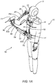
- FIGS. 1A-1D show an example of a support system 10 that includes a harness 15 configured to be worn on a body of a user U, an adaptive arm support 20 for supporting an arm (or optionally both arms, not shown) of the user U, and a tool support system 50 for supported a tool T1 being used by the user U, e.g., for reducing gravitational forces on the arm of a user wearing the system 10 and operating the tool T1, as explained further below.
- the tool support system 50 includes a counterbalance arm 52 including a first end 52a pivotally mounted to the harness 15 by a bracket 70 and a second end 52 including a tool mount 82 attached at an optional gimbal 80.
- the counterbalance arm 52 includes a cassette 54, which employs one or more pulleys, cables, and springs (not shown) to provide a generally upward supporting force to counterbalance the weight of the tool T1.
- the upward supporting force may be responsive to the position of the tool T1, e.g., through the geometry of the counterbalance arm 52, the shape of the pulleys, and/or the rate of the spring(s), in order to provide the desired counterbalancing characteristics.
- the force may be configured to counterbalance all, or a portion of, the weight of the tool T1 consistently in all positions.
- the force may be configured to change as the position of the tool T1 is changed, e.g., raised or lowered as shown in FIGS. 1C and 1D .
- the user U's right arm RA is optionally supported in an adaptive arm support 20, such as those disclosed in application Serial Nos. 13/353,268, filed January 18, 2012 , 13/563,728, filed July 31, 2012 , and 14/102,466, filed December 10, 2013 .
- the adaptive arm support 20 includes a shoulder bracket 22 fixedly mounted to the harness 15, e.g., above or adjacent the shoulder of the user U when the harness 15 is worn, a first arm support segment or bracket 24 pivotally mounted to the shoulder bracket 22 such that the first arm support segment is rotatable about a first or vertical pivot point or axis Dav, and a second arm support segment or bracket 26 pivotally coupled to the first arm support segment 24 such that the second arm support bracket 26 is rotatable about a second or horizontal pivot point or axis Dah generally orthogonal to the first vertical axis Dav.
- the second arm support bracket 26 is configured to extend along the user's upper arm and terminate adjacent the user's elbow, and may include an arm rest, e.g., including padding, securement straps, and the like (not shown), for securely and/or comfortably supporting the arm RA.
- an arm rest e.g., including padding, securement straps, and the like (not shown), for securely and/or comfortably supporting the arm RA.
- the adaptive arm support 20 also includes a cassette 30 including one or more springs, pulleys, and/or other components for applying an offset force to at least partially offset a gravitational force acting on the arm RA as the user U moves and the arm support follows the movement of the user's arm RA.
- a cassette 30 including one or more springs, pulleys, and/or other components for applying an offset force to at least partially offset a gravitational force acting on the arm RA as the user U moves and the arm support follows the movement of the user's arm RA.
- An example of the components of the cassette 30 (with a housing or cover removed) are shown in FIG. 5 , which employs a dual pulley and cable design to manage forces.
- a first or dual path pulley 32 is pivotally joined to the second arm bracket 26 at a pivot point 34 at a location offset from the second pivot point Dah along the second arm bracket 26.
- the dual path pulley 32 may have an integral spring cable pulley 32a and integral cam cable pulley 32b fixed relative to one another yet rotatable together.
- the spring cable pulley 32a may have a substantially circular shape around pivot 34
- the cam cable pulley 32b may have an asymmetrical shape around the pivot 34, e.g., including a lobe that is further from the pivot 34 than the perimeter of the spring cable pulley 32a.
- a spring cable 36a has a first end joined to one end of a spring or other resilient element 38 (with the other end of the spring 38 attached to the second arm support bracket 26), and a second end coupled to the spring cable pulley 32a.
- a cam cable 36b has a first end joined to the cam cable pulley 32b, and a second end joined to a cable anchor 28 secured to the first arm support bracket 24. In the raised arm position shown in FIG.
- the spring 38 may be relatively retracted (i.e., at a lower potential energy state), and the effective radius of the spring cable pulley 32a and integral cam cable pulley 32b may be similar, allowing the spring cable 36a (transmitting the force stored in the spring 38) to have approximately equal influence on the dual path pulley 32 as cam cable 36b.
- the spring 38 is at a higher potential energy state and the dual path pulley 32 has rotated about the pivot 34, which may bring the lobe on the cam cable pulley 32b into a position that presents a larger effective radius, and therefore a mechanical advantage, for the cam cable 36b to act on.
- the spring cable pulley 32a having a smaller effective radius, provides substantially no mechanical advantage for the spring cable 36a.
- the force applied to the user's arm RA may be modified based on the relative vertical position of the arm.
- the harness 15 generally includes a shoulder harness 16 configured to be worn over or around the user's shoulders, an attachment band 17 configured to be worn around the user's torso, e.g., waist or hips, and one or more generally vertical supports or brackets extending between the shoulder harness 16 and the attachment band 17.
- a vertical or front bracket 18 extends between the shoulder harness 16 and the attachment band 17 along the front of the user U, e.g., to provide a rigid support for supporting the tool support system 50.
- one or more back brackets may extend along the back of the user U, e.g., to support the arm support system 20, similar to embodiments in the applications identified elsewhere herein.
- the tool support system 50 may include an adjustable extension bar 68 extending from the cassette 54, e.g., to allow the user U to extend or retract the bar 68 and thereby change the distance between the first and second ends 52a, 52b of the counterbalance arm 52, to accommodate the requirements of the task and the dimensions of the user U.
- the cassette 54 generally includes an elongate bracket or housing carrying one or more compensation elements, e.g., one or more springs, pulleys, cables, and the like (not shown), e.g., similar to the cassette 30 of the arm support system 20 described above and in the applications identified elsewhere herein.
- the cassette 54 joins link arm 78 at the first end 52a of the counterbalance arm 52, which, in turn, joins link arm 74.
- Link arm 74 joins the bracket 70, which is attached to the harness 15.
- Link arms 74 and 78 serve to allow the user U to maneuver the counterbalance arm 52 in the horizontal plane, while providing substantially rigid support in the vertical plane, i.e., to allow the location of the first end 52a of the counterbalance arm 52 to be moved horizontally towards/away from the user U and/or left/right in front of the user U without the first end 52a moving vertically.
- FIG. 1C shows a side view of the counterbalance arm 52 of the tool support system 50 in a substantially raised position.
- cable 60 attaches to anchor 64 and the pulley and spring system (not shown other than representative pulley 58, which may be a single circular or asymmetric pulley or a dual pulley including multiple pulleys with different geometries) within the cassette 54 to provide a configurable counterbalancing force.
- Optional gimbal 80 attached to the second end 52b of the counterbalance arm 52, e.g., to the extension bar 68, may pivot in the vertical plane about horizontal pivot HP2.
- Gimbal 80 may provide a substantially vertical pivot VP4 at which the tool T1 may be attached.
- the link arm 78 is attached to the cassette 54 at vertical pivot VP3, and to the link arm 74 at vertical pivot VP2.
- the link arm 74 is attached to the bracket 70 at vertical pivot VP1.
- the link arms and associated pivots allow the counterbalance arm 50 to be rotated, swung, and extended as required during the task.
- FIG. 1D shows a side view of the counterbalance arm 52 in a substantially lowered position. Consistent with the function described in the applications identified elsewhere herein, the cable 60 is now more extended out of the cassette 54, in response to the motion of the counterbalance arm 52 along path P1.
- FIGS. 2A-2F an exemplary embodiment of a high load adaptive arm support system 100 is shown.
- a user U wears a harness 120 (e.g., including a shoulder harness, attachment band, and one or more vertical supports or brackets), to which is attached an arm support assembly 110.
- the arm support system 100 generally includes a shoulder bracket 112 fixedly mounted to the harness 120, a first arm support bracket 114 pivotally coupled to the shoulder bracket 112 about a first or vertical pivot point or axis VP7, and a second arm support bracket 116 (including upper arm cassette 150) pivotally coupled to the first arm support bracket 114 about a second or horizontal pivot point or axis HP5.
- the arm support assembly 110 may pivot freely relative to the harness 120 at vertical pivot VP7 in response to motions of the user U's right arm RA.
- the arm support assembly 110 may also pivot about horizontal pivot HP5.
- a counterbalancing force may be applied by the upper arm cassette 150, consistent with the function described in the applications identified elsewhere herein.
- the arm support system 110 includes a third arm support bracket 118 (including lower arm cassette 170) pivotally coupled to the second arm support bracket 116 for supporting a tool mount 190.
- the lower arm cassette 170 may provide a counterbalancing force to the third arm support bracket 118 and tool mount 190 (and to at least partially offset the weight of a tool T2), as described below.
- the tool mount for tool T2 is a commercially available gimbal assembly 190, which is attached to the arm support assembly 110 via a gimbal rod 194 and link arm 198.
- the arm support assembly 110 thus attached to the harness 120 and the tool T2, acts to provide a generally upward force to counterbalance the weight of the tool T2, while generally following the motions of the user U's right arm RA during the performance of the task.
- FIG. 2B shows a partial side view of the high load adaptive arm support system 100 of FIG. 2A .
- the right arm RA of the user U and the arm support assembly 110 are shown in a substantially horizontal orientation.
- Upper arm cassette 150 through cable 156 attached at upper anchor 152 (which is secured to the first arm support bracket 114), provides a generally upward counterbalancing force to the second arm support bracket 116.
- the upper anchor 152 may be releasable from the harness 120 if desired to remove the counterbalancing force.
- the lower arm cassette 170 pivotally attached to vertical 4-bar link 162, also provides a generally upward counterbalancing force.
- Horizontal 4-bar link 160 is attached to upper anchor 152 at hinge 154, and to vertical 4-bar link 162 at hinge 164.
- the vertical 4-bar link 162 is attached also to cassette housing 151 at hinge 168.
- the cassette housing 151, the upper anchor 152, the horizontal 4-bar link 160, and the vertical 4-bar link 162 form a 4-bar linkage system, which serves to keep the vertical 4-bar link 162 substantially parallel to upper anchor 152 of the first arm support bracket 114.
- FIG. 2C shows a partial side view of the high load adaptive arm support system 100 of FIG. 2B .
- the right arm RA is shown with the upper arm angled downward, having pivoted about horizontal pivot HP5 along path P2, while the lower arm is still substantially horizontal.
- the upper arm cassette 150 is shown with the cable 156 extended further out of the upper arm cassette 150, as it acts to provide the desired counterbalancing force on the arm RA and tool T2.
- the lower arm cassette 170, through cable 174 and lower anchor 172, also provides a counterbalancing force.
- the 4-bar linkage system (described above) serves to maintain vertical 4-bar link 162 substantially parallel to upper anchor 152.
- the vertical 4-bar link 162 provides the mounting for the lower arm cassette 170, the angle of the lower arm cassette 170 is thus not affected by changes in the angle of the user's upper arm. This serves to keep the counterbalancing force of lower arm cassette 170 substantially independent of the position of the upper arm cassette 150, thereby keeping the counterbalancing force of the lower arm cassette 170 only a function of the angle of that cassette.
- FIG. 2D shows a partial side view of the high load adaptive arm support system 100 of FIG. 2C .
- the right arm RA is shown with the upper arm angled downward, while the lower arm is shown angled upward, having pivoted about horizontal pivot HP7 along path P3. Consistent with the function described in the applications identified elsewhere herein, the cable 174 has retracted into the lower arm cassette 170 in response to the change in position.
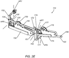
- FIG. 2E shows a perspective view of the arm support assembly 110 of FIGS. 2A-2D .
- Elbow bracket 171 is pivotally mounted to the vertical 4-bar link 162 at vertical pivot VP9.
- the lower arm cassette 170 is pivotally mounted to the elbow bracket 171 at horizontal pivot HP7.
- FIG. 2F shows a perspective view of the arm support assembly 110 of FIG. 2E , with the elbow bracket 171 rotated about vertical pivot VP9, along path P4 (consistent with the user bending their elbow in the horizontal plane).
- the lower arm cassette 170 and lower anchor 172 which are mounted to the elbow bracket 171, rotate with it.
- the elbow bracket 171, mounted to the vertical 4-bar link 162, is also kept substantially parallel to the upper anchor 152, even though it has rotated about vertical pivot VP9.
- the lower anchor 172 may be releasable from the elbow bracket 171 if desired to remove the counterbalancing force.
- FIG. 3A shows a front perspective view of another embodiment of a high load arm support system 220, which may be generally similar to the system 100 of FIGS. 2A-2F , e.g., including an arm support assembly 110, but employs a unique tool mount.
- the arm support assembly 110 is attached to tool mount 230 at or near the user U's wrist.
- the user U is shown holding tool T3, which is supported by the tool mount 230.
- the tool mount 230 may including one or more pivoting and/or swiveling components, e.g., centered on the user U's wrist, to enable natural motion of the wrist while guiding the tool T3 during the task.
- FIG. 3B is a front perspective view of the arm support system 220 of FIG. 3A .
- Tool mount bracket 240 is attached to lower arm cassette 170, and may be adjustable along its length. Pivotally mounted to the tool mount bracket 240 is pivot frame 246. Mounted to the pivot frame 246 is gimbal frame 250. Within the gimbal frame 250 is gimbal ring 254, from which extends gimbal bracket 258. The tool T3 is mounted to the gimbal bracket 258, and may pivot relative to one another.
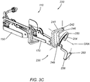
- FIG. 3C is a front perspective view of the arm support system 220 of FIG. 3B , with the tool T3 removed, and with several of the pivoting and swiveling components shown in different positions to demonstrate their features.
- the tool mount bracket 240 is rigidly attached to the lower arm cassette 170, and provides hinge 242 at which the pivot frame 246 is pivotally mounted.
- the gimbal ring 254 is mounted within the gimbal frame 250, and may rotate relative to it about gimbal rotation axis GRA.
- gimbal bracket 258 Extending from the gimbal ring 254 is gimbal bracket 258 to which the tool T3 (not shown) may be attached at socket 260.
- the hinge 242, hinge 248, rotating gimbal ring, and tool socket provide multiple rotational degrees of freedom, e.g., to accommodate motion of the user U's wrist and/or hand during performance of desired tasks.
- FIGS. 4A and 4B show an alternative embodiment of a high load arm support system 300, which differs from the systems shown in FIG. 2 and FIG. 3 in that the counterbalancing cassettes are mounted remotely (instead of on the side of the user U's arm).
- the user U wears a harness 120, as in previous systems.
- Cassettes 330, 360 are shown mounted on the back of the harness 120, although other configurations are possible.
- the function of the cassettes 330 and 360 is to provide a counterbalancing force to the user U's right arm RA, which may vary with arm position. That counterbalancing force transmitted by cables from the cassettes 330, 360, through cable housings 342 and 368, to the components supporting the user U's arm and tool T3.
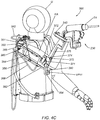
- FIG. 4C is a partial front perspective view of the high load arm support system 300 of FIG. 4B .
- the pulley 350 is attached to upper pulley mount 351.
- Vertical 4-bar link 385, lower 4-bar link 382, upper 4-bar link 380, and 4-bar bracket 384 form a 4-bar linkage that keeps 4-bar bracket 384 parallel to vertical 4-bar link 385, similar to the 4-bar linkage of FIG. 2 .
- Lower pulley mount 371 is mounted on the 4-bar bracket 384, and thus does not rotate as the user U rotates their upper arm.
- Lower pulley 372 is mounted on the lower pulley mount 371.
- Cable 374 transmitting force from cassette 360 through cable housing 368, wraps around the lower pulley 372, and terminates at anchor ring 375 on forearm bracket 376.
- Tool mount bracket 240 of tool mount 230 is attached to forearm bracket 376 (other tool mounting structures are contemplated, such as the embodiment shown in FIG. 2 ).
- arm rests may be provided for the user's upper and lower arms in any of the embodiments herein.
- provisions for the user adjusting the counterbalancing force may be included, for example, a ratchet or knob mechanism that permits the user to increase the force as desired.
- damping or speed control elements may be included as necessary to slow and/or otherwise control the motion of the various counterbalancing mechanisms described herein.
Description
- The present invention relates to a system and method for supporting an arm of a user and a tool.
- Numerous tasks require people to work with their arms outstretched, e.g., while operating hand tools or other equipment that they must at least partially support themselves. Examples include construction, surgery, dentistry, painting, dishwashing, and product assembly. Persons engaged in such activities may experience fatigue from prolonged muscular efforts required to resist the force of gravity on their arms in order to keep them extended. Weak or disabled persons may experience fatigue performing daily tasks. Static arm rests on chairs and work tables are only effective if the task is performed within a relatively restricted area, for example, at a computer keyboard. Tasks that involve a greater range of motion are not aided by static armrests.
-
US 2010/0217163 A1 describes a rotation adjustment apparatus comprising a rotary apparatus which has a plurality of members coupled to each other via a plurality of rotation axes. The rotary apparatus provides a rotational movement of one of the members rotating around the rotation axis with respect to another one of the members; and a rotation restraining means which restrains at least one of a plurality of rotational movements provided by the rotary apparatusWO2009/016478A2 andUS2011/164949A1 form also part of the prior art. - Thus, there is a need for systems that may relieve fatigue experienced by persons performing tasks involving moderate to large ranges of motion and/or operating tools or other equipment.
- According to the present invention there is provided a system and method for supporting an arm of a user while using a tool according to claims 1 and 13.
- The present invention is directed to systems, devices, and methods for supporting a user's arms, for example, to adaptive arm support systems or devices that support one or both of a user's arms, while allowing substantially free motion, e.g., to allow the user to perform one or more tasks for extended periods of time with one or both arms extended.
- In accordance with the invention, a system is provided for supporting an arm of a user while using a tool that includes a harness configured to be worn on a body of a user, the harness comprising a shoulder harness configured to be worn over or around one or both shoulders of the user including a first pivot point above the shoulder of a user when the harness is worn by the user; and an arm support comprising a first arm support segment pivotally coupled to the first pivot point, a second arm support segment pivotally coupled to the first arm support segment for supporting an upper arm of the user, and a third arm support segment pivotally coupled to the second arm support segment for supporting a lower arm of the user. A tool mount is coupled to the third arm support segment, e.g., for receiving a tool such that the tool may be manipulated by a hand of the user supported by the arm support. In addition, the system includes a first set of compensation elements coupled to the second arm support segment for at least partially offsetting a gravitational force acting on the upper arm, and a second set of compensation elements coupled to the third arm support segment for at least partially offsetting a gravitational force acting on the lower arm. The system also includes a linkage coupled between the first arm support segment and the third arm support segment such that a vertical angle of the third arm support segment is not affected by rotation of the second arm support segment.
- In an exemplary embodiment, the compensation elements may be a spring-pulley-cable assembly that is powerless and sensorless, i.e., does not need an electrical power source, motors, and the like. In addition, the tool mount may include a pivot frame pivotally coupled to the third arm support segment. The tool mount may include a gimbal device to provide multiple degrees of freedom, e.g., for positioning the tool adjacent a hand of the arm supported by the arm support assembly. In addition or alternatively, the tool mount may also include one or more compensation elements to at least partially offset a gravitational force acting on the tool received on the second free end.
- In accordance with another example, a method is provided for supporting an arm of a user while using a tool that includes placing a harness on the user, the harness comprising an arm support movable relative to the harness and including an arm rest and a tool mount extending from the harness in front of the user; supporting a portion of the user's arm using the arm support such that the arm support subsequently follows movement of the user's arm; mounting a tool in a free end of the tool mount; and using the tool to perform one or more tasks, the tool mount comprising one or more compensation elements that apply an offset force to at least partially offset a gravitational force acting on the tool as the user moves without substantially interfering in the movement.
- In accordance with still another example, a system is provided for supporting an arm of a user while using a tool that includes a harness configured to be worn on a body of a user, and an arm support pivotally coupled to the harness. The arm support may include a plurality of segments for supporting a user's arm and a tool mount for receiving a tool such that the tool may be manipulated by a hand of the user's arm supported by the arm support. For example, the system may include one or more compensation elements coupled to the arm support for at least partially offsetting a gravitational force acting on the user's arm and/or the tool received on the tool mount.
- In a further example, a body-mounted counterbalance mechanism may be provided for tools that may be mounted at the user's shoulder, e.g., that may substantially conform to the shape of the user's arm as it follows the motion of the user's arm.
- In accordance with the invention, a method is provided for supporting an arm of a user while using a tool that includes placing a harness on the user, the harness comprising an arm support movable relative to the harness; supporting a portion of the user's arm using the arm support such that the arm support subsequently follows movement of the user's arm, the arm support comprising a first segment pivotally coupled to the harness about a first vertical axis adjacent the user's shoulder, a second segment adjacent the user's upper arm pivotally coupled to the first segment such that the second segment is rotatable about a second horizontal axis, and a third segment adjacent the user's forearm and pivotally coupled to the second segment; securing a tool in a tool mount coupled to the third segment; and using the tool to perform one or more tasks, the first and second segments comprising one or more compensation elements that apply an offset force to at least partially offset a gravitational force acting on the tool as the user moves without substantially interfering in the movement. The arm support also comprises a linkage coupled between the first segment and the third segment such that a vertical rotation angle of the third segment is not affected by rotation of the second segment.
- Other aspects and features of the present invention will become apparent from consideration of the following description taken in conjunction with the accompanying drawings.
- The invention is best understood from the following detailed description when read in conjunction with the accompanying drawings. It will be appreciated that the exemplary devices shown in the drawings are not necessarily drawn to scale, with emphasis instead being placed on illustrating the various aspects and features of the illustrated embodiments.
-
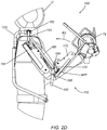
FIG. 1A shows a front perspective view of an example of an arm support system worn by a user including a waist-mounted support system for a tool. -
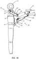
FIG. 1B shows a side view of the system ofFIG. 1A worn by a user. -
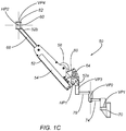
FIGS. 1C and1D show a side view of a counterbalance arm of the system ofFIGS. 1A and1B in substantially raised and lowered positions, respectively. -
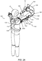
FIG. 2A shows a rear perspective view of an embodiment of a high load adaptive arm support system worn by a user. -
FIGS. 2B-2D show partial side views of the system ofFIG. 2A worn by a user in various positions. -
FIGS. 2E and2F show perspective views of an arm support assembly of the system ofFIGS. 2A-2D in different positions. -
FIG. 3A shows a front perspective view of still another embodiment of a high load arm support system worn by a user including a tool mount. -
FIGS. 3B and3C are perspective views of the arm support of the system ofFIG. 3A with a tool mounted and removed, respectively, from a mount of the arm support. -
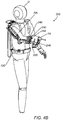
FIGS. 4A and4B are rear and front perspective views, respectively, of yet another embodiment of a high load arm support system worn by a user. -
FIG. 4C is a detail of the system ofFIGS. 4A and4B worn by a user. -
FIG. 5 is a perspective view of an exemplary embodiment of a pulley-spring mechanism that may be included in an arm support system. - Turning to the drawings,
FIGS. 1A-1D show an example of asupport system 10 that includes aharness 15 configured to be worn on a body of a user U, anadaptive arm support 20 for supporting an arm (or optionally both arms, not shown) of the user U, and atool support system 50 for supported a tool T1 being used by the user U, e.g., for reducing gravitational forces on the arm of a user wearing thesystem 10 and operating the tool T1, as explained further below. Generally, thetool support system 50 includes acounterbalance arm 52 including afirst end 52a pivotally mounted to theharness 15 by abracket 70 and asecond end 52 including atool mount 82 attached at anoptional gimbal 80. - The
counterbalance arm 52 includes acassette 54, which employs one or more pulleys, cables, and springs (not shown) to provide a generally upward supporting force to counterbalance the weight of the tool T1. The upward supporting force may be responsive to the position of the tool T1, e.g., through the geometry of thecounterbalance arm 52, the shape of the pulleys, and/or the rate of the spring(s), in order to provide the desired counterbalancing characteristics. For example, the force may be configured to counterbalance all, or a portion of, the weight of the tool T1 consistently in all positions. Alternatively, the force may be configured to change as the position of the tool T1 is changed, e.g., raised or lowered as shown inFIGS. 1C and1D . - As shown in
FIGS. 1A and1B , the user U's right arm RA is optionally supported in anadaptive arm support 20, such as those disclosed in application Serial Nos.13/353,268, filed January 18, 2012 13/563,728, filed July 31, 2012 14/102,466, filed December 10, 2013 adaptive arm support 20 includes ashoulder bracket 22 fixedly mounted to theharness 15, e.g., above or adjacent the shoulder of the user U when theharness 15 is worn, a first arm support segment orbracket 24 pivotally mounted to theshoulder bracket 22 such that the first arm support segment is rotatable about a first or vertical pivot point or axis Dav, and a second arm support segment orbracket 26 pivotally coupled to the firstarm support segment 24 such that the secondarm support bracket 26 is rotatable about a second or horizontal pivot point or axis Dah generally orthogonal to the first vertical axis Dav. The secondarm support bracket 26 is configured to extend along the user's upper arm and terminate adjacent the user's elbow, and may include an arm rest, e.g., including padding, securement straps, and the like (not shown), for securely and/or comfortably supporting the arm RA. - The
adaptive arm support 20 also includes acassette 30 including one or more springs, pulleys, and/or other components for applying an offset force to at least partially offset a gravitational force acting on the arm RA as the user U moves and the arm support follows the movement of the user's arm RA. An example of the components of the cassette 30 (with a housing or cover removed) are shown inFIG. 5 , which employs a dual pulley and cable design to manage forces. A first ordual path pulley 32 is pivotally joined to thesecond arm bracket 26 at apivot point 34 at a location offset from the second pivot point Dah along thesecond arm bracket 26. Thedual path pulley 32 may have an integralspring cable pulley 32a and integralcam cable pulley 32b fixed relative to one another yet rotatable together. Thespring cable pulley 32a may have a substantially circular shape aroundpivot 34, while thecam cable pulley 32b may have an asymmetrical shape around thepivot 34, e.g., including a lobe that is further from thepivot 34 than the perimeter of thespring cable pulley 32a. - A
spring cable 36a has a first end joined to one end of a spring or other resilient element 38 (with the other end of thespring 38 attached to the second arm support bracket 26), and a second end coupled to thespring cable pulley 32a. Acam cable 36b has a first end joined to thecam cable pulley 32b, and a second end joined to acable anchor 28 secured to the firstarm support bracket 24. In the raised arm position shown inFIG. 5 , thespring 38 may be relatively retracted (i.e., at a lower potential energy state), and the effective radius of thespring cable pulley 32a and integralcam cable pulley 32b may be similar, allowing thespring cable 36a (transmitting the force stored in the spring 38) to have approximately equal influence on thedual path pulley 32 ascam cable 36b. When the arm Ar is moved to a lowered position, thespring 38 is at a higher potential energy state and thedual path pulley 32 has rotated about thepivot 34, which may bring the lobe on thecam cable pulley 32b into a position that presents a larger effective radius, and therefore a mechanical advantage, for thecam cable 36b to act on. Thespring cable pulley 32a, having a smaller effective radius, provides substantially no mechanical advantage for thespring cable 36a. Thus, in this arrangement, the force applied to the user's arm RA may be modified based on the relative vertical position of the arm. - Returning to
FIGS. 1A and1B , theharness 15 generally includes ashoulder harness 16 configured to be worn over or around the user's shoulders, anattachment band 17 configured to be worn around the user's torso, e.g., waist or hips, and one or more generally vertical supports or brackets extending between theshoulder harness 16 and theattachment band 17. For example, as shown, a vertical orfront bracket 18 extends between theshoulder harness 16 and theattachment band 17 along the front of the user U, e.g., to provide a rigid support for supporting thetool support system 50. In addition, one or more back brackets (not shown) may extend along the back of the user U, e.g., to support thearm support system 20, similar to embodiments in the applications identified elsewhere herein. - With further reference to
FIG. 1B , thetool support system 50 may include anadjustable extension bar 68 extending from thecassette 54, e.g., to allow the user U to extend or retract thebar 68 and thereby change the distance between the first andsecond ends counterbalance arm 52, to accommodate the requirements of the task and the dimensions of the user U. Thecassette 54 generally includes an elongate bracket or housing carrying one or more compensation elements, e.g., one or more springs, pulleys, cables, and the like (not shown), e.g., similar to thecassette 30 of thearm support system 20 described above and in the applications identified elsewhere herein. - The
cassette 54 joinslink arm 78 at thefirst end 52a of thecounterbalance arm 52, which, in turn, joinslink arm 74.Link arm 74 joins thebracket 70, which is attached to theharness 15.Link arms counterbalance arm 52 in the horizontal plane, while providing substantially rigid support in the vertical plane, i.e., to allow the location of thefirst end 52a of thecounterbalance arm 52 to be moved horizontally towards/away from the user U and/or left/right in front of the user U without thefirst end 52a moving vertically. -
FIG. 1C shows a side view of thecounterbalance arm 52 of thetool support system 50 in a substantially raised position. Consistent with the function described in the applications identified elsewhere herein,cable 60 attaches to anchor 64 and the pulley and spring system (not shown other thanrepresentative pulley 58, which may be a single circular or asymmetric pulley or a dual pulley including multiple pulleys with different geometries) within thecassette 54 to provide a configurable counterbalancing force.Optional gimbal 80, attached to thesecond end 52b of thecounterbalance arm 52, e.g., to theextension bar 68, may pivot in the vertical plane about horizontal pivot HP2.Gimbal 80 may provide a substantially vertical pivot VP4 at which the tool T1 may be attached. These two pivots provide the user U the ability to rotate and tilt the tool T1. Thelink arm 78 is attached to thecassette 54 at vertical pivot VP3, and to thelink arm 74 at vertical pivot VP2. Thelink arm 74, in turn, is attached to thebracket 70 at vertical pivot VP1. The link arms and associated pivots allow thecounterbalance arm 50 to be rotated, swung, and extended as required during the task. -
FIG. 1D shows a side view of thecounterbalance arm 52 in a substantially lowered position. Consistent with the function described in the applications identified elsewhere herein, thecable 60 is now more extended out of thecassette 54, in response to the motion of thecounterbalance arm 52 along path P1. - Turning to
FIGS. 2A-2F , an exemplary embodiment of a high load adaptivearm support system 100 is shown. Consistent with the applications identified elsewhere herein, a user U wears a harness 120 (e.g., including a shoulder harness, attachment band, and one or more vertical supports or brackets), to which is attached anarm support assembly 110. Similar to other embodiments, thearm support system 100 generally includes ashoulder bracket 112 fixedly mounted to theharness 120, a firstarm support bracket 114 pivotally coupled to theshoulder bracket 112 about a first or vertical pivot point or axis VP7, and a second arm support bracket 116 (including upper arm cassette 150) pivotally coupled to the firstarm support bracket 114 about a second or horizontal pivot point or axis HP5. Thus, thearm support assembly 110 may pivot freely relative to theharness 120 at vertical pivot VP7 in response to motions of the user U's right arm RA. Thearm support assembly 110 may also pivot about horizontal pivot HP5. A counterbalancing force may be applied by theupper arm cassette 150, consistent with the function described in the applications identified elsewhere herein. - In addition, the
arm support system 110 includes a third arm support bracket 118 (including lower arm cassette 170) pivotally coupled to the secondarm support bracket 116 for supporting atool mount 190. Thelower arm cassette 170 may provide a counterbalancing force to the thirdarm support bracket 118 and tool mount 190 (and to at least partially offset the weight of a tool T2), as described below. In the embodiment shown, the tool mount for tool T2 is a commerciallyavailable gimbal assembly 190, which is attached to thearm support assembly 110 via agimbal rod 194 andlink arm 198. Thearm support assembly 110, thus attached to theharness 120 and the tool T2, acts to provide a generally upward force to counterbalance the weight of the tool T2, while generally following the motions of the user U's right arm RA during the performance of the task. -
FIG. 2B shows a partial side view of the high load adaptivearm support system 100 ofFIG. 2A . The right arm RA of the user U and thearm support assembly 110 are shown in a substantially horizontal orientation.Upper arm cassette 150, throughcable 156 attached at upper anchor 152 (which is secured to the first arm support bracket 114), provides a generally upward counterbalancing force to the secondarm support bracket 116. Optionally, theupper anchor 152 may be releasable from theharness 120 if desired to remove the counterbalancing force. Thelower arm cassette 170, pivotally attached to vertical 4-bar link 162, also provides a generally upward counterbalancing force. Horizontal 4-bar link 160 is attached toupper anchor 152 athinge 154, and to vertical 4-bar link 162 athinge 164. The vertical 4-bar link 162 is attached also tocassette housing 151 athinge 168. Thecassette housing 151, theupper anchor 152, the horizontal 4-bar link 160, and the vertical 4-bar link 162 form a 4-bar linkage system, which serves to keep the vertical 4-bar link 162 substantially parallel toupper anchor 152 of the firstarm support bracket 114. -
FIG. 2C shows a partial side view of the high load adaptivearm support system 100 ofFIG. 2B . The right arm RA is shown with the upper arm angled downward, having pivoted about horizontal pivot HP5 along path P2, while the lower arm is still substantially horizontal. Consistent with the function described in the applications identified elsewhere herein, theupper arm cassette 150 is shown with thecable 156 extended further out of theupper arm cassette 150, as it acts to provide the desired counterbalancing force on the arm RA and tool T2. Thelower arm cassette 170, throughcable 174 andlower anchor 172, also provides a counterbalancing force. Although the user's upper arm has been lowered, the 4-bar linkage system (described above) serves to maintain vertical 4-bar link 162 substantially parallel toupper anchor 152. Because the vertical 4-bar link 162 provides the mounting for thelower arm cassette 170, the angle of thelower arm cassette 170 is thus not affected by changes in the angle of the user's upper arm. This serves to keep the counterbalancing force oflower arm cassette 170 substantially independent of the position of theupper arm cassette 150, thereby keeping the counterbalancing force of thelower arm cassette 170 only a function of the angle of that cassette. -
FIG. 2D shows a partial side view of the high load adaptivearm support system 100 ofFIG. 2C . The right arm RA is shown with the upper arm angled downward, while the lower arm is shown angled upward, having pivoted about horizontal pivot HP7 along path P3. Consistent with the function described in the applications identified elsewhere herein, thecable 174 has retracted into thelower arm cassette 170 in response to the change in position. -
FIG. 2E shows a perspective view of thearm support assembly 110 ofFIGS. 2A-2D .Elbow bracket 171 is pivotally mounted to the vertical 4-bar link 162 at vertical pivot VP9. Thelower arm cassette 170 is pivotally mounted to theelbow bracket 171 at horizontal pivot HP7. -
FIG. 2F shows a perspective view of thearm support assembly 110 ofFIG. 2E , with theelbow bracket 171 rotated about vertical pivot VP9, along path P4 (consistent with the user bending their elbow in the horizontal plane). Thelower arm cassette 170 andlower anchor 172, which are mounted to theelbow bracket 171, rotate with it. Theelbow bracket 171, mounted to the vertical 4-bar link 162, is also kept substantially parallel to theupper anchor 152, even though it has rotated about vertical pivot VP9. Optionally, thelower anchor 172 may be releasable from theelbow bracket 171 if desired to remove the counterbalancing force. -
FIG. 3A shows a front perspective view of another embodiment of a high loadarm support system 220, which may be generally similar to thesystem 100 ofFIGS. 2A-2F , e.g., including anarm support assembly 110, but employs a unique tool mount. Thearm support assembly 110 is attached totool mount 230 at or near the user U's wrist. The user U is shown holding tool T3, which is supported by thetool mount 230. Thetool mount 230 may including one or more pivoting and/or swiveling components, e.g., centered on the user U's wrist, to enable natural motion of the wrist while guiding the tool T3 during the task. -
FIG. 3B is a front perspective view of thearm support system 220 ofFIG. 3A .Tool mount bracket 240 is attached tolower arm cassette 170, and may be adjustable along its length. Pivotally mounted to thetool mount bracket 240 ispivot frame 246. Mounted to thepivot frame 246 isgimbal frame 250. Within thegimbal frame 250 isgimbal ring 254, from which extendsgimbal bracket 258. The tool T3 is mounted to thegimbal bracket 258, and may pivot relative to one another. -
FIG. 3C is a front perspective view of thearm support system 220 ofFIG. 3B , with the tool T3 removed, and with several of the pivoting and swiveling components shown in different positions to demonstrate their features. Thetool mount bracket 240 is rigidly attached to thelower arm cassette 170, and provideshinge 242 at which thepivot frame 246 is pivotally mounted. Thepivot frame 246, in turn, provideshinge 248, generally orthogonal to hinge 242, at which thegimbal frame 250 is pivotally attached. Thegimbal ring 254 is mounted within thegimbal frame 250, and may rotate relative to it about gimbal rotation axis GRA. Extending from thegimbal ring 254 isgimbal bracket 258 to which the tool T3 (not shown) may be attached atsocket 260. Thehinge 242, hinge 248, rotating gimbal ring, and tool socket provide multiple rotational degrees of freedom, e.g., to accommodate motion of the user U's wrist and/or hand during performance of desired tasks. -
FIGS. 4A and4B show an alternative embodiment of a high loadarm support system 300, which differs from the systems shown inFIG. 2 andFIG. 3 in that the counterbalancing cassettes are mounted remotely (instead of on the side of the user U's arm). Generally, the user U wears aharness 120, as in previous systems.Cassettes harness 120, although other configurations are possible. As described in the applications identified elsewhere herein, the function of thecassettes cassettes cable housings -
FIG. 4C is a partial front perspective view of the high loadarm support system 300 ofFIG. 4B .Cable 354, transmitting force fromcassette 330 throughcable housing 342, wraps aroundpulley 350 and terminates atanchor ring 356 on lower 4-bar link 382. Thepulley 350 is attached toupper pulley mount 351. Vertical 4-bar link 385, lower 4-bar link 382, upper 4-bar link 380, and 4-bar bracket 384 form a 4-bar linkage that keeps 4-bar bracket 384 parallel to vertical 4-bar link 385, similar to the 4-bar linkage ofFIG. 2 .Lower pulley mount 371 is mounted on the 4-bar bracket 384, and thus does not rotate as the user U rotates their upper arm.Lower pulley 372 is mounted on thelower pulley mount 371.Cable 374, transmitting force fromcassette 360 throughcable housing 368, wraps around thelower pulley 372, and terminates atanchor ring 375 onforearm bracket 376.Tool mount bracket 240 oftool mount 230 is attached to forearm bracket 376 (other tool mounting structures are contemplated, such as the embodiment shown inFIG. 2 ). - Although not shown in all images, arm rests may be provided for the user's upper and lower arms in any of the embodiments herein.
- In addition or alternatively, provisions for the user adjusting the counterbalancing force may be included, for example, a ratchet or knob mechanism that permits the user to increase the force as desired.
- In addition or alternatively, damping or speed control elements may be included as necessary to slow and/or otherwise control the motion of the various counterbalancing mechanisms described herein.
- The foregoing disclosure of the exemplary embodiments has been presented for purposes of illustration and description. It is not intended to be exhaustive or to limit the invention to the precise forms disclosed. Many variations and modifications of the embodiments described herein will be apparent to one of ordinary skill in the art in light of the above disclosure.
- It will be appreciated that elements or components shown with any embodiment herein are exemplary for the specific embodiment and may be used on or in combination with other embodiments disclosed herein.
- While the invention is susceptible to various modifications, and alternative forms, specific examples thereof have been shown in the drawings and are herein described in detail. It should be understood, however, that the invention is not to be limited to the particular forms or methods disclosed, but to the contrary, the invention is to cover all modifications, equivalents and alternatives falling within the scope of the appended claims.
Claims (13)
- A system (100, 220) for supporting an arm of a user while using a tool, comprising:a harness (120) configured to be worn on a body of a user, the harness comprising a shoulder harness (112) configured to be worn over or around one or both shoulders of the user including a first pivot point (VP7) above the shoulder of a user when the harness is worn by the user;an arm support comprising a first arm support segment (114) pivotally coupled to the first pivot point (VP7), a second arm support segment (116) pivotally coupled to the first arm support segment (114) for supporting an upper arm of the user, and a third arm support segment (118) pivotally coupled to the second arm support segment for supporting a lower arm of the user; anda first set of compensation elements coupled to the second arm support segment for at least partially offsetting a gravitational force acting on the upper arm, and a second set of compensation elements coupled to the third arm support segment for at least partially offsetting a gravitational force acting on the lower arm; characterised in that the system further comprises:a tool mount (190, 230) coupled to the third arm support segment (118); anda linkage coupled between the first arm support segment (114) and the third arm support segment (118)such that a vertical angle of the third arm support segment (118) is not affected by rotation of the second arm support segment (116).
- The system of claim 1, wherein the first set of compensation elements are mounted at least partially on the second arm support segment, and, optionally, wherein the second set of compensation elements are mounted at least partially on the third arm support segment.
- The system of claim 1, wherein the first and second sets of compensation elements are mounted on the harness, and wherein a plurality of cables couple the first and second sets of compensation elements to the second and third arm support segments, respectively.
- The system of claim 1, wherein the first arm support segment (114) is configured to rotate about a first vertical axis to follow horizontal rotation of the user's arm.
- The system of claim 4, wherein the second arm support segment (116) is configured to rotate about a second horizontal axis to follow vertical rotation of the user's upper arm and, optionally, wherein the third arm support segment (118) is configured to rotate about a third axis to follow rotation of the user's lower arm relative to the user's upper arm.
- The system of any preceding claim, wherein a second end of the first arm support segment (114) is pivotally coupled to a first end of the second arm support segment (116) at a first horizontal pivot point (HP5), and a second end of the second arm support segment (116) is disposed adjacent a first end of the third arm support segment (118), wherein the linkage comprises a first link (162) pivotally coupled to the second end of the second arm support segment and a second link (160) pivotally coupled between the second end of the first arm support segment (114) and the first link (162)such that the second link (160) extends substantially parallel to the second arm support segment (116) and the first link (162) remains substantially vertical when the second arm support segment is rotated, and wherein a first end of the third arm support segment is pivotally coupled to the first link.
- The system of claim 6, wherein the first and second sets of compensation elements comprise first and second spring-pulley-cable assemblies, respectively, wherein an offset force of the first spring-pulley-cable assembly is variable based on a rotation angle of the second arm support segment independent of a rotation angle of the third arm support segment, and wherein an offset force of the second spring-pulley-cable assembly is variable based on the rotation angle of the third arm support segment independent of the rotation angle of the second arm support segment.
- The system of claim 6, wherein the linkage further comprises an elbow bracket (171) pivotally coupled to the first link (162) about a vertical pivot point (VP9), and wherein the first end of the third arm support segment (118) is pivotally coupled to the elbow bracket (171) about a horizontal pivot point (HP7), wherein the vertical pivot point accommodates bending of the forearm of the user within a substantially horizontal plane.
- The system of claim 8, wherein the elbow bracket (171) nests at least partially in the first link when the second and third arm support segments are substantially straight.
- The system of any preceding claims, wherein the tool mount (230) comprises a pivot frame (246) pivotally coupled to the third arm support segment.
- The system of claim 10, wherein the tool mount (230) further comprises a gimbal device (250, 254, 258) pivotally coupled to the pivot frame (246) to provide multiple degrees of freedom for a tool secured to the tool mount.
- The system of claim 11, wherein the tool mount further comprises a socket (260) coupled to the gimbal device (250, 254, 258) for receiving a portion of the tool.
- A method for supporting an arm of a user while using a tool, comprising:placing a harness on the user, the harness comprising an arm support movable relative to the harness;supporting a portion of the user's arm using the arm support such that the arm support subsequently follows movement of the user's arm, the arm support comprising a first segment pivotally coupled to the harness about a first vertical axis adjacent the user's shoulder, a second segment adjacent the user's upper arm pivotally coupled to the first segment such that the second segment is rotatable about a second horizontal axis, and a third segment adjacent the user's forearm and pivotally coupled to the second segment, wherein the arm support comprises a linkage coupled between the first segment and the third segment such that a vertical rotation angle of the third segment is not affected by roation of the second segment;securing a tool in a tool mount coupled to the third segment; andusing the tool to perform one or more tasks, the first and second segments comprising one or more compensation elements that apply an offset force to at least partially offset a gravitational force acting on the tool as the user moves without substantially interfering in the movement.
Applications Claiming Priority (2)
| Application Number | Priority Date | Filing Date | Title |
|---|---|---|---|
| US201461977060P | 2014-04-08 | 2014-04-08 | |
| PCT/US2015/025011 WO2015157473A1 (en) | 2014-04-08 | 2015-04-08 | Heavy capacity arm support systems |
Publications (3)
| Publication Number | Publication Date |
|---|---|
| EP3129197A1 EP3129197A1 (en) | 2017-02-15 |
| EP3129197A4 EP3129197A4 (en) | 2018-03-28 |
| EP3129197B1 true EP3129197B1 (en) | 2021-03-31 |
Family
ID=54288385
Family Applications (1)
| Application Number | Title | Priority Date | Filing Date |
|---|---|---|---|
| EP15776499.4A Active EP3129197B1 (en) | 2014-04-08 | 2015-04-08 | Heavy capacity arm support systems |
Country Status (4)
| Country | Link |
|---|---|
| US (3) | US9427865B2 (en) |
| EP (1) | EP3129197B1 (en) |
| JP (1) | JP6600316B2 (en) |
| WO (1) | WO2015157473A1 (en) |
Families Citing this family (42)
| Publication number | Priority date | Publication date | Assignee | Title |
|---|---|---|---|---|
| EP3007868B1 (en) * | 2013-06-12 | 2023-06-07 | Skel-Ex Holding B.V. | Device with improved actuating means |
| JP6600316B2 (en) * | 2014-04-08 | 2019-10-30 | エンハンス テクノロジーズ,リミテッド ライアビリティー カンパニー | Arm support system for weight |
| US10391627B2 (en) * | 2015-05-18 | 2019-08-27 | The Regents Of The University Of California | Arm supporting exoskeleton with a variable force generator |
| US10639785B2 (en) | 2015-05-18 | 2020-05-05 | The Regents Of The University Of California | Variable force generators for arm supporting exoskeletons |
| GB2557554B (en) | 2015-10-30 | 2021-03-24 | Ekso Bionics Inc | Human exoskeleton devices for heavy tool support and use |
| DE102015015562B4 (en) * | 2015-12-03 | 2019-05-29 | Rheinisch-Westfälische Technische Hochschule (Rwth) Aachen | power tool |
| US10058994B2 (en) * | 2015-12-22 | 2018-08-28 | Ekso Bionics, Inc. | Exoskeleton and method of providing an assistive torque to an arm of a wearer |
| US10569413B2 (en) | 2015-12-22 | 2020-02-25 | Ekso Bionics, Inc. | Exoskeleton and method of providing an assistive torque to an arm of a wearer |
| TWI600421B (en) * | 2016-01-05 | 2017-10-01 | 國立成功大學 | Shoulder joint rehabilitation assistive device |
| WO2017157941A1 (en) * | 2016-03-14 | 2017-09-21 | Helmut-Schmidt-Universität / Universität Der Bundeswehr Hamburg | Exoskeleton for a human being |
| CN105640739B (en) * | 2016-03-21 | 2017-08-25 | 哈尔滨工业大学 | A kind of upper limb healing ectoskeleton balanced based on space gravity |
| JP7046372B2 (en) * | 2016-05-20 | 2022-04-04 | エンハンス テクノロジーズ,リミテッド ライアビリティー カンパニー | Arm support system |
| EP3278938B1 (en) * | 2016-08-04 | 2019-11-06 | Airbus Operations GmbH | Wearable apparatus for assisting a human when performing a load-involved task |
| US11045940B2 (en) | 2016-09-14 | 2021-06-29 | Ekso Bionics, Inc. | Devices for the support of tools |
| CN106667722B (en) * | 2016-10-30 | 2018-10-09 | 北京工业大学 | A kind of man-machine space gravity balance ectoskeleton |
| DE102016121203A1 (en) | 2016-11-07 | 2018-05-09 | Otto Bock Healthcare Gmbh | Device for supporting an arm |
| DE102016122282A1 (en) | 2016-11-18 | 2018-05-24 | Helmut-Schmidt-Universität Universität der Bundeswehr Hamburg | SYSTEM AND METHOD FOR REDUCING FORCES AFFORDING ON A SPINE |
| DE102016123153A1 (en) | 2016-11-30 | 2018-05-30 | Helmut-Schmidt-Universität Universität der Bundeswehr Hamburg | DEVICE AND METHOD FOR MUSCLE POWER SUPPORT |
| WO2018111853A1 (en) * | 2016-12-13 | 2018-06-21 | Abilitech Medical, Inc. | Upper torso augmentation system and method |
| US20180193107A1 (en) * | 2017-01-12 | 2018-07-12 | Electronics And Telecommunications Research Institute | Balance arm apparatus for supporting heavy tools |
| JP6839758B2 (en) * | 2017-04-19 | 2021-03-10 | 株式会社マキタ | Work aid |
| FR3065387A1 (en) * | 2017-04-25 | 2018-10-26 | Pierre Davezac | EXOSQUELET PASSIVE ENERGY AND COLLABORATIVE |
| US10918559B2 (en) | 2017-04-25 | 2021-02-16 | Ossur Iceland Ehf | Interface system in an exoskeleton |
| WO2018213363A1 (en) | 2017-05-15 | 2018-11-22 | Enhance Technologies, LLC | Arm support systems |
| DE102017112436B4 (en) | 2017-06-06 | 2019-05-29 | Ottobock Se & Co. Kgaa | Device for supporting at least one arm of a user |
| TWI667049B (en) | 2017-09-25 | 2019-08-01 | 林宗正 | Sensor module capable of reducing noise |
| CN111148606B (en) | 2017-09-28 | 2023-04-07 | 奥索冰岛有限公司 | Body engaging device |
| DE102017123574A1 (en) * | 2017-10-10 | 2019-04-11 | Exoiq Gmbh | MUSCLE POWER SUPPORT SYSTEM |
| DE102018108416A1 (en) | 2018-04-10 | 2019-10-10 | Ottobock Se & Co. Kgaa | Device for supporting at least one arm |
| USD876654S1 (en) | 2018-04-24 | 2020-02-25 | Ossur Iceland Ehf | Posterior strut |
| CN110815171B (en) * | 2018-08-09 | 2023-03-21 | 埃克苏仿生公司 | Exoskeleton and method for providing assistance torque to a wearer's arm |
| DE102018119754A1 (en) | 2018-08-14 | 2020-02-20 | Ottobock Se & Co. Kgaa | Device for supporting at least one arm of a user |
| DE102018119755A1 (en) * | 2018-08-14 | 2020-02-20 | Ottobock Se & Co. Kgaa | Device for supporting at least one arm of a user |
| DE102018127553B4 (en) | 2018-11-05 | 2020-11-05 | Ottobock Se & Co. Kgaa | Device for supporting at least one arm of a user |
| JP2020130629A (en) * | 2019-02-20 | 2020-08-31 | 宗正 林 | Sensor module with reduced noise |
| WO2020222938A1 (en) * | 2019-05-02 | 2020-11-05 | Virginia Tech Intellectual Properties, Inc. | Gravity compensation mechanisms and methods |
| FR3108053B1 (en) * | 2020-03-10 | 2022-02-11 | Psa Automobiles Sa | Exoskeleton-type effort assistance device |
| CN111805574B (en) * | 2020-05-25 | 2022-11-04 | 南京航空航天大学 | Wearable rope-driven mechanical arm system |
| EP4067009B1 (en) | 2021-03-31 | 2023-09-06 | Ottobock SE & Co. KGaA | Device for supporting at least one upper arm |
| CN113499222B (en) * | 2021-07-15 | 2022-06-03 | 天津市第四中心医院 | Auxiliary rehabilitation movable frame for hands of neurology patients |
| USD1011398S1 (en) | 2021-08-13 | 2024-01-16 | Festool Gmbh | Wearable robotic exoskeleton |
| US20230054601A1 (en) * | 2021-08-20 | 2023-02-23 | John-Thomas Cameron | Handsfree, body-mounted apparatus for supporting high-pressure hoses |
Family Cites Families (42)
| Publication number | Priority date | Publication date | Assignee | Title |
|---|---|---|---|---|
| DE2615209A1 (en) * | 1975-04-15 | 1976-10-28 | Teufel Wilh Jul Fa | UNIVERSAL ORTHESIS |
| US4298149A (en) | 1978-01-17 | 1981-11-03 | Panavision, Incorporated | Body harness for cinematographer |
| US5111983A (en) | 1986-02-10 | 1992-05-12 | Simmons Elex M | Camera stabilizing device |
| JPH02153115A (en) | 1988-12-05 | 1990-06-12 | Toa Harbor Works Co Ltd | Floating method and device for submerging caisson |
| US5220704A (en) * | 1991-02-01 | 1993-06-22 | Aei | Ergonomic tool support apparatus and material removal system |
| US5360196A (en) * | 1992-09-15 | 1994-11-01 | Garrett W. Brown | Adjustable, iso-elastic support apparatus |
| JP2761574B2 (en) * | 1994-07-06 | 1998-06-04 | 工業技術院長 | Method of controlling force assist device and device thereof |
| AU6480096A (en) * | 1995-06-30 | 1997-02-05 | Ross-Hime Designs, Inc. | Robotic manipulator |
| JP2889859B2 (en) | 1996-08-29 | 1999-05-10 | 保 柳沢 | Shoulder support device |
| US5873847A (en) | 1996-11-14 | 1999-02-23 | Lenjoy Engineering, Inc. | Articulated splints and goniometric hinge for the same |
| US5888235A (en) * | 1997-01-07 | 1999-03-30 | Sarcos, Inc. | Body-powered prosthetic arm |
| JPH11253504A (en) * | 1998-03-12 | 1999-09-21 | Sanyo Electric Co Ltd | Upper limb motion assisting device |
| KR100299210B1 (en) | 1999-03-12 | 2001-09-22 | 박호군 | Master device having force reflective function |
| US7918808B2 (en) | 2000-09-20 | 2011-04-05 | Simmons John C | Assistive clothing |
| JP2003211377A (en) * | 2002-01-18 | 2003-07-29 | Hitachi Ltd | Manipulating operation support device and support method |
| JP2005255410A (en) * | 2004-03-15 | 2005-09-22 | Shiraishi Fuhaku Seihin Kk | Man-tool integrated tool |
| JP4110203B2 (en) * | 2005-10-11 | 2008-07-02 | 松下電器産業株式会社 | Operation support device |
| US7862524B2 (en) * | 2006-03-23 | 2011-01-04 | Carignan Craig R | Portable arm exoskeleton for shoulder rehabilitation |
| JP2008006161A (en) * | 2006-06-30 | 2008-01-17 | Shinano Kenshi Co Ltd | Power assist device and sensor |
| JP4585542B2 (en) | 2007-05-31 | 2010-11-24 | 博 宇土 | Upper limb lifting support device |
| FR2917323B1 (en) * | 2007-06-12 | 2009-10-02 | Commissariat Energie Atomique | FRONT ROTATION MECHANISM AND ORTHESIS COMPRISING SUCH A MECHANISM |
| EP2178680B1 (en) * | 2007-07-30 | 2014-05-07 | Scuola Superiore Di Studi Universitari S. Anna | Wearable mechatronic device |
| WO2009029693A1 (en) | 2007-08-30 | 2009-03-05 | Brown Garrett W | Articulated human arm support |
| EP2188565B1 (en) * | 2007-09-17 | 2018-09-05 | BROWN, Garrett W. | Gimbal assembly for tool support |
| CN101848687B (en) * | 2007-09-27 | 2012-12-26 | 国立大学法人筑波大学 | Turn adjusting apparatus and method for controlling turning apparatus |
| JP5169469B2 (en) | 2008-05-15 | 2013-03-27 | 学校法人東京理科大学 | Upper arm holding device and upper arm assist device |
| GB2472036B (en) | 2009-07-22 | 2013-12-04 | David George Sherry | A mechanical device to relieve the pain of repetitive strain injury in the muscles, joints and tendons of the human arm shoulder and back |
| KR101572852B1 (en) * | 2010-01-06 | 2015-12-01 | 삼성전자 주식회사 | Compact exoskeleton arm support device for gravity compensation |
| JP5515116B2 (en) * | 2010-06-03 | 2014-06-11 | 国立大学法人東京農工大学 | Power assist suit |
| KR101241800B1 (en) | 2010-12-09 | 2013-03-14 | 전자부품연구원 | Exoskeleton Apparatus For Assistant physical strength |
| CA2861566C (en) | 2011-01-18 | 2019-09-17 | Mark C. Doyle | Adaptive arm support systems and methods for use |
| JP5804310B2 (en) * | 2011-05-24 | 2015-11-04 | 学校法人東京理科大学 | Upper arm holding device and upper arm assist device |
| JP5909063B2 (en) * | 2011-09-06 | 2016-04-26 | 国立大学法人 和歌山大学 | Power assist robot |
| US9095981B2 (en) | 2012-01-11 | 2015-08-04 | Garrett W. Brown | Load and torque resistant caliper exoskeleton |
| EP2836097B1 (en) | 2012-04-09 | 2017-06-07 | John Christopher Fawcett | Support vest |
| FR2991224B1 (en) * | 2012-06-04 | 2014-06-27 | Commissariat Energie Atomique | ARM OF EXOSQUELET WITH ACTUATOR |
| FR2993811A1 (en) * | 2012-07-26 | 2014-01-31 | Pierre Andre Davezac | Semi-passive exoskeleton for carrying and handling e.g. riveters in metallurgical industry, has arm provided with structure of parallelograms, where arm preserves isoelastic and passive qualities after short energy consumption |
| US9999534B2 (en) | 2012-07-31 | 2018-06-19 | Enhance Technologies, LLC | Adaptive arm support systems and methods for use |
| US9737374B2 (en) * | 2012-12-11 | 2017-08-22 | Levitate Technologies, Inc. | Adaptive arm support systems and methods for use |
| WO2015099858A2 (en) * | 2013-09-30 | 2015-07-02 | Board Of Regents, The University Of Texas System | Upper-body robotic exoskeleton |
| JP6600316B2 (en) * | 2014-04-08 | 2019-10-30 | エンハンス テクノロジーズ,リミテッド ライアビリティー カンパニー | Arm support system for weight |
| US10391627B2 (en) * | 2015-05-18 | 2019-08-27 | The Regents Of The University Of California | Arm supporting exoskeleton with a variable force generator |
-
2015
- 2015-04-08 JP JP2016561349A patent/JP6600316B2/en active Active
- 2015-04-08 WO PCT/US2015/025011 patent/WO2015157473A1/en active Application Filing
- 2015-04-08 EP EP15776499.4A patent/EP3129197B1/en active Active
- 2015-04-08 US US14/682,065 patent/US9427865B2/en active Active
-
2016
- 2016-08-29 US US15/250,797 patent/US10208893B2/en active Active
-
2019
- 2019-02-18 US US16/278,708 patent/US10816135B2/en active Active
Non-Patent Citations (1)
| Title |
|---|
| None * |
Also Published As
| Publication number | Publication date |
|---|---|
| US20150316204A1 (en) | 2015-11-05 |
| US9427865B2 (en) | 2016-08-30 |
| EP3129197A4 (en) | 2018-03-28 |
| EP3129197A1 (en) | 2017-02-15 |
| US20190249825A1 (en) | 2019-08-15 |
| JP6600316B2 (en) | 2019-10-30 |
| US10816135B2 (en) | 2020-10-27 |
| US10208893B2 (en) | 2019-02-19 |
| JP2017512666A (en) | 2017-05-25 |
| US20160363264A1 (en) | 2016-12-15 |
| WO2015157473A1 (en) | 2015-10-15 |
Similar Documents
| Publication | Publication Date | Title |
|---|---|---|
| EP3129197B1 (en) | Heavy capacity arm support systems | |
| US10617551B2 (en) | Arm support systems | |
| JP6027025B2 (en) | Adaptive arm support system and method of use | |
| JP6515265B2 (en) | Adaptive arm support system and method of using the same | |
| EP2185036B1 (en) | Articulated human arm support | |
| AU2013359431B2 (en) | Adaptive arm support systems and methods for use | |
| US11779504B2 (en) | Wearable apparatus for increasing muscular force | |
| JP7018651B2 (en) | Head support system and how to use it | |
| CN106575040A (en) | Headset having versatile eye orientation adjustment system | |
| US20220168887A1 (en) | Head support systems and methods for use | |
| US20190126795A1 (en) | Arm support systems | |
| WO2023003868A1 (en) | Flexible exoskeleton frames and arm support systems and methods for using them | |
| WO2023158880A1 (en) | Head support systems and methods for use | |
| WO2012027433A1 (en) | Combination support system |
Legal Events
| Date | Code | Title | Description |
|---|---|---|---|
| STAA | Information on the status of an ep patent application or granted ep patent |
Free format text: STATUS: THE INTERNATIONAL PUBLICATION HAS BEEN MADE |
|
| PUAI | Public reference made under article 153(3) epc to a published international application that has entered the european phase |
Free format text: ORIGINAL CODE: 0009012 |
|
| STAA | Information on the status of an ep patent application or granted ep patent |
Free format text: STATUS: REQUEST FOR EXAMINATION WAS MADE |
|
| 17P | Request for examination filed |
Effective date: 20161026 |
|
| AK | Designated contracting states |
Kind code of ref document: A1 Designated state(s): AL AT BE BG CH CY CZ DE DK EE ES FI FR GB GR HR HU IE IS IT LI LT LU LV MC MK MT NL NO PL PT RO RS SE SI SK SM TR |
|
| AX | Request for extension of the european patent |
Extension state: BA ME |
|
| DAV | Request for validation of the european patent (deleted) | ||
| DAX | Request for extension of the european patent (deleted) | ||
| A4 | Supplementary search report drawn up and despatched |
Effective date: 20180226 |
|
| RAP1 | Party data changed (applicant data changed or rights of an application transferred) |
Owner name: ENHANCE TECHNOLOGIES, LLC |
|
| RIC1 | Information provided on ipc code assigned before grant |
Ipc: B25J 19/00 20060101ALI20180220BHEP Ipc: B25J 9/00 20060101AFI20180220BHEP |
|
| REG | Reference to a national code |
Ref country code: DE Ref legal event code: R079 Ref document number: 602015067498 Country of ref document: DE Free format text: PREVIOUS MAIN CLASS: B25J0011000000 Ipc: B25J0009000000 |
|
| RIC1 | Information provided on ipc code assigned before grant |
Ipc: B25J 19/00 20060101ALI20200923BHEP Ipc: B25J 9/00 20060101AFI20200923BHEP |
|
| GRAP | Despatch of communication of intention to grant a patent |
Free format text: ORIGINAL CODE: EPIDOSNIGR1 |
|
| STAA | Information on the status of an ep patent application or granted ep patent |
Free format text: STATUS: GRANT OF PATENT IS INTENDED |
|
| INTG | Intention to grant announced |
Effective date: 20201030 |
|
| RIN1 | Information on inventor provided before grant (corrected) |
Inventor name: DOYLE, MARK, C. |
|
| GRAS | Grant fee paid |
Free format text: ORIGINAL CODE: EPIDOSNIGR3 |
|
| GRAA | (expected) grant |
Free format text: ORIGINAL CODE: 0009210 |
|
| STAA | Information on the status of an ep patent application or granted ep patent |
Free format text: STATUS: THE PATENT HAS BEEN GRANTED |
|
| AK | Designated contracting states |
Kind code of ref document: B1 Designated state(s): AL AT BE BG CH CY CZ DE DK EE ES FI FR GB GR HR HU IE IS IT LI LT LU LV MC MK MT NL NO PL PT RO RS SE SI SK SM TR |
|
| REG | Reference to a national code |
Ref country code: GB Ref legal event code: FG4D Ref country code: CH Ref legal event code: EP |
|
| REG | Reference to a national code |
Ref country code: DE Ref legal event code: R096 Ref document number: 602015067498 Country of ref document: DE Ref country code: AT Ref legal event code: REF Ref document number: 1376415 Country of ref document: AT Kind code of ref document: T Effective date: 20210415 |
|
| REG | Reference to a national code |
Ref country code: IE Ref legal event code: FG4D |
|
| REG | Reference to a national code |
Ref country code: LT Ref legal event code: MG9D |
|
| PG25 | Lapsed in a contracting state [announced via postgrant information from national office to epo] |
Ref country code: FI Free format text: LAPSE BECAUSE OF FAILURE TO SUBMIT A TRANSLATION OF THE DESCRIPTION OR TO PAY THE FEE WITHIN THE PRESCRIBED TIME-LIMIT Effective date: 20210331 Ref country code: HR Free format text: LAPSE BECAUSE OF FAILURE TO SUBMIT A TRANSLATION OF THE DESCRIPTION OR TO PAY THE FEE WITHIN THE PRESCRIBED TIME-LIMIT Effective date: 20210331 Ref country code: NO Free format text: LAPSE BECAUSE OF FAILURE TO SUBMIT A TRANSLATION OF THE DESCRIPTION OR TO PAY THE FEE WITHIN THE PRESCRIBED TIME-LIMIT Effective date: 20210630 Ref country code: BG Free format text: LAPSE BECAUSE OF FAILURE TO SUBMIT A TRANSLATION OF THE DESCRIPTION OR TO PAY THE FEE WITHIN THE PRESCRIBED TIME-LIMIT Effective date: 20210630 |
|
| PG25 | Lapsed in a contracting state [announced via postgrant information from national office to epo] |
Ref country code: SE Free format text: LAPSE BECAUSE OF FAILURE TO SUBMIT A TRANSLATION OF THE DESCRIPTION OR TO PAY THE FEE WITHIN THE PRESCRIBED TIME-LIMIT Effective date: 20210331 Ref country code: LV Free format text: LAPSE BECAUSE OF FAILURE TO SUBMIT A TRANSLATION OF THE DESCRIPTION OR TO PAY THE FEE WITHIN THE PRESCRIBED TIME-LIMIT Effective date: 20210331 Ref country code: RS Free format text: LAPSE BECAUSE OF FAILURE TO SUBMIT A TRANSLATION OF THE DESCRIPTION OR TO PAY THE FEE WITHIN THE PRESCRIBED TIME-LIMIT Effective date: 20210331 |
|
| REG | Reference to a national code |
Ref country code: NL Ref legal event code: MP Effective date: 20210331 |
|
| REG | Reference to a national code |
Ref country code: AT Ref legal event code: MK05 Ref document number: 1376415 Country of ref document: AT Kind code of ref document: T Effective date: 20210331 |
|
| PG25 | Lapsed in a contracting state [announced via postgrant information from national office to epo] |
Ref country code: AT Free format text: LAPSE BECAUSE OF FAILURE TO SUBMIT A TRANSLATION OF THE DESCRIPTION OR TO PAY THE FEE WITHIN THE PRESCRIBED TIME-LIMIT Effective date: 20210331 Ref country code: SM Free format text: LAPSE BECAUSE OF FAILURE TO SUBMIT A TRANSLATION OF THE DESCRIPTION OR TO PAY THE FEE WITHIN THE PRESCRIBED TIME-LIMIT Effective date: 20210331 Ref country code: NL Free format text: LAPSE BECAUSE OF FAILURE TO SUBMIT A TRANSLATION OF THE DESCRIPTION OR TO PAY THE FEE WITHIN THE PRESCRIBED TIME-LIMIT Effective date: 20210331 Ref country code: LT Free format text: LAPSE BECAUSE OF FAILURE TO SUBMIT A TRANSLATION OF THE DESCRIPTION OR TO PAY THE FEE WITHIN THE PRESCRIBED TIME-LIMIT Effective date: 20210331 Ref country code: EE Free format text: LAPSE BECAUSE OF FAILURE TO SUBMIT A TRANSLATION OF THE DESCRIPTION OR TO PAY THE FEE WITHIN THE PRESCRIBED TIME-LIMIT Effective date: 20210331 Ref country code: CZ Free format text: LAPSE BECAUSE OF FAILURE TO SUBMIT A TRANSLATION OF THE DESCRIPTION OR TO PAY THE FEE WITHIN THE PRESCRIBED TIME-LIMIT Effective date: 20210331 |
|
| PG25 | Lapsed in a contracting state [announced via postgrant information from national office to epo] |
Ref country code: IS Free format text: LAPSE BECAUSE OF FAILURE TO SUBMIT A TRANSLATION OF THE DESCRIPTION OR TO PAY THE FEE WITHIN THE PRESCRIBED TIME-LIMIT Effective date: 20210731 Ref country code: RO Free format text: LAPSE BECAUSE OF FAILURE TO SUBMIT A TRANSLATION OF THE DESCRIPTION OR TO PAY THE FEE WITHIN THE PRESCRIBED TIME-LIMIT Effective date: 20210331 Ref country code: SK Free format text: LAPSE BECAUSE OF FAILURE TO SUBMIT A TRANSLATION OF THE DESCRIPTION OR TO PAY THE FEE WITHIN THE PRESCRIBED TIME-LIMIT Effective date: 20210331 Ref country code: ES Free format text: LAPSE BECAUSE OF FAILURE TO SUBMIT A TRANSLATION OF THE DESCRIPTION OR TO PAY THE FEE WITHIN THE PRESCRIBED TIME-LIMIT Effective date: 20210331 Ref country code: PT Free format text: LAPSE BECAUSE OF FAILURE TO SUBMIT A TRANSLATION OF THE DESCRIPTION OR TO PAY THE FEE WITHIN THE PRESCRIBED TIME-LIMIT Effective date: 20210802 Ref country code: PL Free format text: LAPSE BECAUSE OF FAILURE TO SUBMIT A TRANSLATION OF THE DESCRIPTION OR TO PAY THE FEE WITHIN THE PRESCRIBED TIME-LIMIT Effective date: 20210331 |
|
| PG25 | Lapsed in a contracting state [announced via postgrant information from national office to epo] |
Ref country code: LU Free format text: LAPSE BECAUSE OF NON-PAYMENT OF DUE FEES Effective date: 20210408 |
|
| REG | Reference to a national code |
Ref country code: DE Ref legal event code: R097 Ref document number: 602015067498 Country of ref document: DE |
|
| REG | Reference to a national code |
Ref country code: BE Ref legal event code: MM Effective date: 20210430 |
|
| PG25 | Lapsed in a contracting state [announced via postgrant information from national office to epo] |
Ref country code: LI Free format text: LAPSE BECAUSE OF NON-PAYMENT OF DUE FEES Effective date: 20210430 Ref country code: MC Free format text: LAPSE BECAUSE OF FAILURE TO SUBMIT A TRANSLATION OF THE DESCRIPTION OR TO PAY THE FEE WITHIN THE PRESCRIBED TIME-LIMIT Effective date: 20210331 Ref country code: AL Free format text: LAPSE BECAUSE OF FAILURE TO SUBMIT A TRANSLATION OF THE DESCRIPTION OR TO PAY THE FEE WITHIN THE PRESCRIBED TIME-LIMIT Effective date: 20210331 Ref country code: CH Free format text: LAPSE BECAUSE OF NON-PAYMENT OF DUE FEES Effective date: 20210430 Ref country code: DK Free format text: LAPSE BECAUSE OF FAILURE TO SUBMIT A TRANSLATION OF THE DESCRIPTION OR TO PAY THE FEE WITHIN THE PRESCRIBED TIME-LIMIT Effective date: 20210331 |
|
| PLBE | No opposition filed within time limit |
Free format text: ORIGINAL CODE: 0009261 |
|
| STAA | Information on the status of an ep patent application or granted ep patent |
Free format text: STATUS: NO OPPOSITION FILED WITHIN TIME LIMIT |
|
| 26N | No opposition filed |
Effective date: 20220104 |
|
| PG25 | Lapsed in a contracting state [announced via postgrant information from national office to epo] |
Ref country code: IE Free format text: LAPSE BECAUSE OF NON-PAYMENT OF DUE FEES Effective date: 20210408 |
|
| PG25 | Lapsed in a contracting state [announced via postgrant information from national office to epo] |
Ref country code: IS Free format text: LAPSE BECAUSE OF FAILURE TO SUBMIT A TRANSLATION OF THE DESCRIPTION OR TO PAY THE FEE WITHIN THE PRESCRIBED TIME-LIMIT Effective date: 20210731 |
|
| PG25 | Lapsed in a contracting state [announced via postgrant information from national office to epo] |
Ref country code: IT Free format text: LAPSE BECAUSE OF FAILURE TO SUBMIT A TRANSLATION OF THE DESCRIPTION OR TO PAY THE FEE WITHIN THE PRESCRIBED TIME-LIMIT Effective date: 20210331 Ref country code: BE Free format text: LAPSE BECAUSE OF NON-PAYMENT OF DUE FEES Effective date: 20210430 |
|
| REG | Reference to a national code |
Ref country code: DE Ref legal event code: R081 Ref document number: 602015067498 Country of ref document: DE Owner name: LEVITATE TECHNOLOGIES, INC., SAN DIEGO, US Free format text: FORMER OWNER: ENHANCE TECHNOLOGIES, LLC, SAN DIEGO, CALIF., US |
|
| REG | Reference to a national code |
Ref country code: FR Ref legal event code: PLFP Year of fee payment: 9 Ref country code: GB Ref legal event code: 732E Free format text: REGISTERED BETWEEN 20230316 AND 20230322 |
|
| PG25 | Lapsed in a contracting state [announced via postgrant information from national office to epo] |
Ref country code: HU Free format text: LAPSE BECAUSE OF FAILURE TO SUBMIT A TRANSLATION OF THE DESCRIPTION OR TO PAY THE FEE WITHIN THE PRESCRIBED TIME-LIMIT; INVALID AB INITIO Effective date: 20150408 |
|
| PG25 | Lapsed in a contracting state [announced via postgrant information from national office to epo] |
Ref country code: CY Free format text: LAPSE BECAUSE OF FAILURE TO SUBMIT A TRANSLATION OF THE DESCRIPTION OR TO PAY THE FEE WITHIN THE PRESCRIBED TIME-LIMIT Effective date: 20210331 |
|
| PG25 | Lapsed in a contracting state [announced via postgrant information from national office to epo] |
Ref country code: GR Free format text: LAPSE BECAUSE OF FAILURE TO SUBMIT A TRANSLATION OF THE DESCRIPTION OR TO PAY THE FEE WITHIN THE PRESCRIBED TIME-LIMIT Effective date: 20210331 |
|
| PGFP | Annual fee paid to national office [announced via postgrant information from national office to epo] |
Ref country code: FR Payment date: 20230412 Year of fee payment: 9 Ref country code: DE Payment date: 20230419 Year of fee payment: 9 |
|
| PGFP | Annual fee paid to national office [announced via postgrant information from national office to epo] |
Ref country code: GB Payment date: 20230417 Year of fee payment: 9 |