EP3129088B1 - Inhalation training device and system for practicing of an inhalation process of a patient - Google Patents
Inhalation training device and system for practicing of an inhalation process of a patient Download PDFInfo
- Publication number
- EP3129088B1 EP3129088B1 EP15722065.8A EP15722065A EP3129088B1 EP 3129088 B1 EP3129088 B1 EP 3129088B1 EP 15722065 A EP15722065 A EP 15722065A EP 3129088 B1 EP3129088 B1 EP 3129088B1
- Authority
- EP
- European Patent Office
- Prior art keywords
- inhalation
- training device
- inhaler
- inhalation training
- patient
- Prior art date
- Legal status (The legal status is an assumption and is not a legal conclusion. Google has not performed a legal analysis and makes no representation as to the accuracy of the status listed.)
- Active
Links
Images



Classifications
-
- A—HUMAN NECESSITIES
- A61—MEDICAL OR VETERINARY SCIENCE; HYGIENE
- A61B—DIAGNOSIS; SURGERY; IDENTIFICATION
- A61B5/00—Measuring for diagnostic purposes; Identification of persons
- A61B5/08—Measuring devices for evaluating the respiratory organs
- A61B5/087—Measuring breath flow
-
- A—HUMAN NECESSITIES
- A61—MEDICAL OR VETERINARY SCIENCE; HYGIENE
- A61M—DEVICES FOR INTRODUCING MEDIA INTO, OR ONTO, THE BODY; DEVICES FOR TRANSDUCING BODY MEDIA OR FOR TAKING MEDIA FROM THE BODY; DEVICES FOR PRODUCING OR ENDING SLEEP OR STUPOR
- A61M11/00—Sprayers or atomisers specially adapted for therapeutic purposes
- A61M11/006—Sprayers or atomisers specially adapted for therapeutic purposes operated by applying mechanical pressure to the liquid to be sprayed or atomised
- A61M11/007—Syringe-type or piston-type sprayers or atomisers
-
- A—HUMAN NECESSITIES
- A61—MEDICAL OR VETERINARY SCIENCE; HYGIENE
- A61M—DEVICES FOR INTRODUCING MEDIA INTO, OR ONTO, THE BODY; DEVICES FOR TRANSDUCING BODY MEDIA OR FOR TAKING MEDIA FROM THE BODY; DEVICES FOR PRODUCING OR ENDING SLEEP OR STUPOR
- A61M15/00—Inhalators
-
- A—HUMAN NECESSITIES
- A61—MEDICAL OR VETERINARY SCIENCE; HYGIENE
- A61M—DEVICES FOR INTRODUCING MEDIA INTO, OR ONTO, THE BODY; DEVICES FOR TRANSDUCING BODY MEDIA OR FOR TAKING MEDIA FROM THE BODY; DEVICES FOR PRODUCING OR ENDING SLEEP OR STUPOR
- A61M15/00—Inhalators
- A61M15/0001—Details of inhalators; Constructional features thereof
- A61M15/0021—Mouthpieces therefor
-
- A—HUMAN NECESSITIES
- A61—MEDICAL OR VETERINARY SCIENCE; HYGIENE
- A61M—DEVICES FOR INTRODUCING MEDIA INTO, OR ONTO, THE BODY; DEVICES FOR TRANSDUCING BODY MEDIA OR FOR TAKING MEDIA FROM THE BODY; DEVICES FOR PRODUCING OR ENDING SLEEP OR STUPOR
- A61M15/00—Inhalators
- A61M15/0065—Inhalators with dosage or measuring devices
- A61M15/0068—Indicating or counting the number of dispensed doses or of remaining doses
-
- A—HUMAN NECESSITIES
- A63—SPORTS; GAMES; AMUSEMENTS
- A63B—APPARATUS FOR PHYSICAL TRAINING, GYMNASTICS, SWIMMING, CLIMBING, OR FENCING; BALL GAMES; TRAINING EQUIPMENT
- A63B21/00—Exercising apparatus for developing or strengthening the muscles or joints of the body by working against a counterforce, with or without measuring devices
- A63B21/008—Exercising apparatus for developing or strengthening the muscles or joints of the body by working against a counterforce, with or without measuring devices using hydraulic or pneumatic force-resisters
- A63B21/0084—Exercising apparatus for developing or strengthening the muscles or joints of the body by working against a counterforce, with or without measuring devices using hydraulic or pneumatic force-resisters by moving the surrounding water
-
- A—HUMAN NECESSITIES
- A63—SPORTS; GAMES; AMUSEMENTS
- A63B—APPARATUS FOR PHYSICAL TRAINING, GYMNASTICS, SWIMMING, CLIMBING, OR FENCING; BALL GAMES; TRAINING EQUIPMENT
- A63B21/00—Exercising apparatus for developing or strengthening the muscles or joints of the body by working against a counterforce, with or without measuring devices
- A63B21/008—Exercising apparatus for developing or strengthening the muscles or joints of the body by working against a counterforce, with or without measuring devices using hydraulic or pneumatic force-resisters
- A63B21/0085—Exercising apparatus for developing or strengthening the muscles or joints of the body by working against a counterforce, with or without measuring devices using hydraulic or pneumatic force-resisters using pneumatic force-resisters
- A63B21/0088—Exercising apparatus for developing or strengthening the muscles or joints of the body by working against a counterforce, with or without measuring devices using hydraulic or pneumatic force-resisters using pneumatic force-resisters by moving the surrounding air
-
- A—HUMAN NECESSITIES
- A63—SPORTS; GAMES; AMUSEMENTS
- A63B—APPARATUS FOR PHYSICAL TRAINING, GYMNASTICS, SWIMMING, CLIMBING, OR FENCING; BALL GAMES; TRAINING EQUIPMENT
- A63B23/00—Exercising apparatus specially adapted for particular parts of the body
- A63B23/18—Exercising apparatus specially adapted for particular parts of the body for improving respiratory function
-
- A—HUMAN NECESSITIES
- A61—MEDICAL OR VETERINARY SCIENCE; HYGIENE
- A61B—DIAGNOSIS; SURGERY; IDENTIFICATION
- A61B2505/00—Evaluating, monitoring or diagnosing in the context of a particular type of medical care
- A61B2505/09—Rehabilitation or training
-
- A—HUMAN NECESSITIES
- A61—MEDICAL OR VETERINARY SCIENCE; HYGIENE
- A61B—DIAGNOSIS; SURGERY; IDENTIFICATION
- A61B2562/00—Details of sensors; Constructional details of sensor housings or probes; Accessories for sensors
- A61B2562/02—Details of sensors specially adapted for in-vivo measurements
- A61B2562/0204—Acoustic sensors
-
- A—HUMAN NECESSITIES
- A61—MEDICAL OR VETERINARY SCIENCE; HYGIENE
- A61M—DEVICES FOR INTRODUCING MEDIA INTO, OR ONTO, THE BODY; DEVICES FOR TRANSDUCING BODY MEDIA OR FOR TAKING MEDIA FROM THE BODY; DEVICES FOR PRODUCING OR ENDING SLEEP OR STUPOR
- A61M2205/00—General characteristics of the apparatus
- A61M2205/02—General characteristics of the apparatus characterised by a particular materials
-
- A—HUMAN NECESSITIES
- A61—MEDICAL OR VETERINARY SCIENCE; HYGIENE
- A61M—DEVICES FOR INTRODUCING MEDIA INTO, OR ONTO, THE BODY; DEVICES FOR TRANSDUCING BODY MEDIA OR FOR TAKING MEDIA FROM THE BODY; DEVICES FOR PRODUCING OR ENDING SLEEP OR STUPOR
- A61M2205/00—General characteristics of the apparatus
- A61M2205/05—General characteristics of the apparatus combined with other kinds of therapy
- A61M2205/056—General characteristics of the apparatus combined with other kinds of therapy with active exercise
-
- A—HUMAN NECESSITIES
- A61—MEDICAL OR VETERINARY SCIENCE; HYGIENE
- A61M—DEVICES FOR INTRODUCING MEDIA INTO, OR ONTO, THE BODY; DEVICES FOR TRANSDUCING BODY MEDIA OR FOR TAKING MEDIA FROM THE BODY; DEVICES FOR PRODUCING OR ENDING SLEEP OR STUPOR
- A61M2205/00—General characteristics of the apparatus
- A61M2205/27—General characteristics of the apparatus preventing use
-
- A—HUMAN NECESSITIES
- A61—MEDICAL OR VETERINARY SCIENCE; HYGIENE
- A61M—DEVICES FOR INTRODUCING MEDIA INTO, OR ONTO, THE BODY; DEVICES FOR TRANSDUCING BODY MEDIA OR FOR TAKING MEDIA FROM THE BODY; DEVICES FOR PRODUCING OR ENDING SLEEP OR STUPOR
- A61M2205/00—General characteristics of the apparatus
- A61M2205/27—General characteristics of the apparatus preventing use
- A61M2205/276—General characteristics of the apparatus preventing use preventing unwanted use
-
- A—HUMAN NECESSITIES
- A61—MEDICAL OR VETERINARY SCIENCE; HYGIENE
- A61M—DEVICES FOR INTRODUCING MEDIA INTO, OR ONTO, THE BODY; DEVICES FOR TRANSDUCING BODY MEDIA OR FOR TAKING MEDIA FROM THE BODY; DEVICES FOR PRODUCING OR ENDING SLEEP OR STUPOR
- A61M2205/00—General characteristics of the apparatus
- A61M2205/33—Controlling, regulating or measuring
- A61M2205/3331—Pressure; Flow
- A61M2205/3334—Measuring or controlling the flow rate
-
- A—HUMAN NECESSITIES
- A61—MEDICAL OR VETERINARY SCIENCE; HYGIENE
- A61M—DEVICES FOR INTRODUCING MEDIA INTO, OR ONTO, THE BODY; DEVICES FOR TRANSDUCING BODY MEDIA OR FOR TAKING MEDIA FROM THE BODY; DEVICES FOR PRODUCING OR ENDING SLEEP OR STUPOR
- A61M2205/00—General characteristics of the apparatus
- A61M2205/33—Controlling, regulating or measuring
- A61M2205/3375—Acoustical, e.g. ultrasonic, measuring means
-
- A—HUMAN NECESSITIES
- A61—MEDICAL OR VETERINARY SCIENCE; HYGIENE
- A61M—DEVICES FOR INTRODUCING MEDIA INTO, OR ONTO, THE BODY; DEVICES FOR TRANSDUCING BODY MEDIA OR FOR TAKING MEDIA FROM THE BODY; DEVICES FOR PRODUCING OR ENDING SLEEP OR STUPOR
- A61M2205/00—General characteristics of the apparatus
- A61M2205/35—Communication
- A61M2205/3546—Range
-
- A—HUMAN NECESSITIES
- A61—MEDICAL OR VETERINARY SCIENCE; HYGIENE
- A61M—DEVICES FOR INTRODUCING MEDIA INTO, OR ONTO, THE BODY; DEVICES FOR TRANSDUCING BODY MEDIA OR FOR TAKING MEDIA FROM THE BODY; DEVICES FOR PRODUCING OR ENDING SLEEP OR STUPOR
- A61M2205/00—General characteristics of the apparatus
- A61M2205/35—Communication
- A61M2205/3546—Range
- A61M2205/3561—Range local, e.g. within room or hospital
-
- A—HUMAN NECESSITIES
- A61—MEDICAL OR VETERINARY SCIENCE; HYGIENE
- A61M—DEVICES FOR INTRODUCING MEDIA INTO, OR ONTO, THE BODY; DEVICES FOR TRANSDUCING BODY MEDIA OR FOR TAKING MEDIA FROM THE BODY; DEVICES FOR PRODUCING OR ENDING SLEEP OR STUPOR
- A61M2205/00—General characteristics of the apparatus
- A61M2205/35—Communication
- A61M2205/3576—Communication with non implanted data transmission devices, e.g. using external transmitter or receiver
- A61M2205/3584—Communication with non implanted data transmission devices, e.g. using external transmitter or receiver using modem, internet or Bluetooth®
-
- A—HUMAN NECESSITIES
- A61—MEDICAL OR VETERINARY SCIENCE; HYGIENE
- A61M—DEVICES FOR INTRODUCING MEDIA INTO, OR ONTO, THE BODY; DEVICES FOR TRANSDUCING BODY MEDIA OR FOR TAKING MEDIA FROM THE BODY; DEVICES FOR PRODUCING OR ENDING SLEEP OR STUPOR
- A61M2205/00—General characteristics of the apparatus
- A61M2205/35—Communication
- A61M2205/3576—Communication with non implanted data transmission devices, e.g. using external transmitter or receiver
- A61M2205/3592—Communication with non implanted data transmission devices, e.g. using external transmitter or receiver using telemetric means, e.g. radio or optical transmission
-
- A—HUMAN NECESSITIES
- A61—MEDICAL OR VETERINARY SCIENCE; HYGIENE
- A61M—DEVICES FOR INTRODUCING MEDIA INTO, OR ONTO, THE BODY; DEVICES FOR TRANSDUCING BODY MEDIA OR FOR TAKING MEDIA FROM THE BODY; DEVICES FOR PRODUCING OR ENDING SLEEP OR STUPOR
- A61M2205/00—General characteristics of the apparatus
- A61M2205/50—General characteristics of the apparatus with microprocessors or computers
- A61M2205/502—User interfaces, e.g. screens or keyboards
-
- A—HUMAN NECESSITIES
- A61—MEDICAL OR VETERINARY SCIENCE; HYGIENE
- A61M—DEVICES FOR INTRODUCING MEDIA INTO, OR ONTO, THE BODY; DEVICES FOR TRANSDUCING BODY MEDIA OR FOR TAKING MEDIA FROM THE BODY; DEVICES FOR PRODUCING OR ENDING SLEEP OR STUPOR
- A61M2205/00—General characteristics of the apparatus
- A61M2205/50—General characteristics of the apparatus with microprocessors or computers
- A61M2205/52—General characteristics of the apparatus with microprocessors or computers with memories providing a history of measured variating parameters of apparatus or patient
-
- A—HUMAN NECESSITIES
- A61—MEDICAL OR VETERINARY SCIENCE; HYGIENE
- A61M—DEVICES FOR INTRODUCING MEDIA INTO, OR ONTO, THE BODY; DEVICES FOR TRANSDUCING BODY MEDIA OR FOR TAKING MEDIA FROM THE BODY; DEVICES FOR PRODUCING OR ENDING SLEEP OR STUPOR
- A61M2205/00—General characteristics of the apparatus
- A61M2205/58—Means for facilitating use, e.g. by people with impaired vision
- A61M2205/581—Means for facilitating use, e.g. by people with impaired vision by audible feedback
-
- A—HUMAN NECESSITIES
- A61—MEDICAL OR VETERINARY SCIENCE; HYGIENE
- A61M—DEVICES FOR INTRODUCING MEDIA INTO, OR ONTO, THE BODY; DEVICES FOR TRANSDUCING BODY MEDIA OR FOR TAKING MEDIA FROM THE BODY; DEVICES FOR PRODUCING OR ENDING SLEEP OR STUPOR
- A61M2205/00—General characteristics of the apparatus
- A61M2205/58—Means for facilitating use, e.g. by people with impaired vision
- A61M2205/583—Means for facilitating use, e.g. by people with impaired vision by visual feedback
-
- A—HUMAN NECESSITIES
- A61—MEDICAL OR VETERINARY SCIENCE; HYGIENE
- A61M—DEVICES FOR INTRODUCING MEDIA INTO, OR ONTO, THE BODY; DEVICES FOR TRANSDUCING BODY MEDIA OR FOR TAKING MEDIA FROM THE BODY; DEVICES FOR PRODUCING OR ENDING SLEEP OR STUPOR
- A61M2230/00—Measuring parameters of the user
- A61M2230/40—Respiratory characteristics
-
- A—HUMAN NECESSITIES
- A63—SPORTS; GAMES; AMUSEMENTS
- A63B—APPARATUS FOR PHYSICAL TRAINING, GYMNASTICS, SWIMMING, CLIMBING, OR FENCING; BALL GAMES; TRAINING EQUIPMENT
- A63B24/00—Electric or electronic controls for exercising apparatus of preceding groups; Controlling or monitoring of exercises, sportive games, training or athletic performances
- A63B24/0062—Monitoring athletic performances, e.g. for determining the work of a user on an exercise apparatus, the completed jogging or cycling distance
- A63B2024/0065—Evaluating the fitness, e.g. fitness level or fitness index
-
- A—HUMAN NECESSITIES
- A63—SPORTS; GAMES; AMUSEMENTS
- A63B—APPARATUS FOR PHYSICAL TRAINING, GYMNASTICS, SWIMMING, CLIMBING, OR FENCING; BALL GAMES; TRAINING EQUIPMENT
- A63B24/00—Electric or electronic controls for exercising apparatus of preceding groups; Controlling or monitoring of exercises, sportive games, training or athletic performances
- A63B24/0087—Electric or electronic controls for exercising apparatus of groups A63B21/00 - A63B23/00, e.g. controlling load
- A63B2024/0096—Electric or electronic controls for exercising apparatus of groups A63B21/00 - A63B23/00, e.g. controlling load using performance related parameters for controlling electronic or video games or avatars
-
- A—HUMAN NECESSITIES
- A63—SPORTS; GAMES; AMUSEMENTS
- A63B—APPARATUS FOR PHYSICAL TRAINING, GYMNASTICS, SWIMMING, CLIMBING, OR FENCING; BALL GAMES; TRAINING EQUIPMENT
- A63B71/00—Games or sports accessories not covered in groups A63B1/00 - A63B69/00
- A63B71/06—Indicating or scoring devices for games or players, or for other sports activities
- A63B71/0619—Displays, user interfaces and indicating devices, specially adapted for sport equipment, e.g. display mounted on treadmills
- A63B71/0622—Visual, audio or audio-visual systems for entertaining, instructing or motivating the user
- A63B2071/0625—Emitting sound, noise or music
-
- A—HUMAN NECESSITIES
- A63—SPORTS; GAMES; AMUSEMENTS
- A63B—APPARATUS FOR PHYSICAL TRAINING, GYMNASTICS, SWIMMING, CLIMBING, OR FENCING; BALL GAMES; TRAINING EQUIPMENT
- A63B2220/00—Measuring of physical parameters relating to sporting activity
- A63B2220/50—Force related parameters
- A63B2220/54—Torque
-
- A—HUMAN NECESSITIES
- A63—SPORTS; GAMES; AMUSEMENTS
- A63B—APPARATUS FOR PHYSICAL TRAINING, GYMNASTICS, SWIMMING, CLIMBING, OR FENCING; BALL GAMES; TRAINING EQUIPMENT
- A63B2225/00—Miscellaneous features of sport apparatus, devices or equipment
- A63B2225/50—Wireless data transmission, e.g. by radio transmitters or telemetry
Definitions
- This invention relates to an inhalation training device for practicing of an inhalation process of a patient according to the preamble of claim 1, and to an inhalation training system for practicing of an inhalation process of a patient.
- Drugs which are to be inhaled constitute a preferred therapy for patients with asthma, a chronically obstructive pulmonary disease or other chronic or acute conditions or diseases of the respiratory tract.
- inhalers are used for inhalation of drugs.
- the most frequently used inhalers are pressurized metered-dose inhalers (pMDls) and dry powder inhalers (DPIs).
- pMDIs were developed to supply a precise amount or dose of a drug in the form of a cloud of aerosol droplets to the lungs of the patient when the latter inhales.
- Dry powder inhalers are made such that when the patient inhales they supply a metered amount of dry pulverized particles to the lungs.
- An alternative inhaler is shown e.g. in WO 2008/151796 A1 .
- This inhaler delivers a metered dose of medication as a slow-moving, soft mist through a nozzle system without use of any propellant.
- the effectiveness of drugs which are to be inhaled depends largely on the way the inhaler is used by the patient. Optimally, the correct amount of the drug travels to the desired regions of the lungs at the correct instant of time. Otherwise, the therapeutic effect is reduced and/or the risk of contrary effects is increased.
- inhalation generally proceeds subconsciously and develops over the course of a lifetime, it is however especially difficult for a patient to change his inhalation in order to increase the effectiveness of a drug which is to be inhaled. Rather, it is known that many patients again use suboptimum inhalation even a short time after instruction. Therefore repeated, preferably regular practicing (in particular used as synonym for training) of inhalation and its checking are recommended.
- Inhalation training systems were developed for this purpose.
- Known inhalation training systems differ among others with respect to the inhalation model for which the patient is to be trained, with respect to the type of feedback to the patient (for example acoustically or visually), with respect to the measured variable (for example inhaled volume, volumetric flow or flow rate or mass flow which is produced during inhalation, velocity of the inhaled particles during the inhalation process), with respect to sensors and actuators (for example mechanical, magnetic or electronic) and with respect to size, handling and costs.
- Some inhalation training systems use inhalers which are available on the market, while other inhalation training systems copy or emulate inhalers or parts of them.
- EP 1 993 642 A1 shows an inhalation training device for practicing of an inhalation process of a patient.
- the known inhalation training device comprises a housing attachable to and detachable from a mouthpiece of an inhaler designed to provide a drug to the patient and a microphone adapted to measure the airflow occurring in the mouthpiece of the inhaler during an inhalation process of the patient.
- the known inhalation training device may further comprise data communication means for communication with e.g. a computer or a device adapted to forward information from monitoring device to a doctor or other person for analysis and evaluation.
- US 2009/314292 A1 which forms the starting point of this invention, discloses an interactive apparatus and method for sensing and measuring real-time characteristic patterns of a subject's use of a dry powder inhaler.
- the devices can be used in a wired or wireless communication mode to communicate with a display to assess the subject's usage of the inhalation system, to evaluate the performance of the inhalation system and/or to detect the characteristics profile of a dry powder formulation emitted from the inhalation system in use.
- the apparatus can include a detachable sensing and monitoring device, which can be used as needed by a patient or a health provider in training or gathering information from the patient's inhalation maneuvers and then removed from the dry powder inhaler.
- the detachable sensing and monitoring device can be adapted to a mouthpiece of the dry powder inhaler.
- the apparatus can comprise a sensor, for example a microphone, positioned in the air pathway of the mouthpiece.
- the sensor can alternatively be positioned within the sensing and monitoring device.
- Object of the present invention is to provide an inhalation training device and an inhalation training system enabling an effective, simple, reliable, comfortable and/or cost-efficient training of an inhalation process of a patient and/or a simple, cost-efficient, robust and/or regulatory compliant structure and/or a precise measurement of a flow generated by the patient during training and/or a patient-friendly real-time feedback.
- the microphone is positioned near an air-vent of the mouthpiece of the inhaler, when the inhalation training device is attached to the mouthpiece of the inhaler.
- This embodiment does not change the aerodynamic behavior of the flow path of the inhaler. In that manner, the medical compliance of the inhaler is not affected by the presence (or absence) of the inhalation training device.
- the housing comprises a pad and/or a sleeve around the microphone, in particular made of foam plastic or soft silicone.
- a pad and/or a sleeve around the microphone in particular made of foam plastic or soft silicone.
- insulation of the microphone is improved and vibrations coupling from the inhalation training device into the microphone are reduced. This will further reduce handling noise and improve flow measurement accuracy.
- the microphone is an electret microphone.
- the microphone is adapted to measure the noise of the airflow through the air-vent of the mouthpiece of the inhaler. It is well known from acoustics that sound travels well in most solid materials. When a patient inhales using the inhaler, the flow path within the inhaler creates a characteristic flow noise sound depending on flow rate and turbulences. Some of this sound is transmitted through the solid structure of the inhaler. As losses in the solid material are small, it is in principle possible to detect the sound anywhere on the inhaler surface.
- the preferred embodiment of measuring the noise of the airflow through the air-vent of the mouthpiece of the inhaler enables an effective and reliable training and a precise flow measurement during training.
- the microphone exhibits directionality, in particular a cardioid, super-cardioid, hyper-cardioid or a bi-directional characteristic.
- the directional microphone characteristic allows for the microphone itself cancelling out signals that originate from outside the mouthpiece of the inhaler, however not affecting sounds that originate from within. Thus, influence from ambient noise during training can be reduced and flow measurement accuracy can be increased.
- the inhalation training device provides an interface to an electronic device.
- the electronic device preferably is a portable communications device capable of capturing, transmitting and/or outputting information and which can be easily transported by an individual.
- portable communications devices are telephony, data transmission, games, text processing, table processing, image processing, photography and music playback.
- portable communications devices are mobile phones, smartphones, tablet PCs, handhelds and PDAs.
- This embodiment enables exploitation of the functionality of the electronic device, especially for processing and/or evaluation of the signal measured by the microphone of the inhalation training device and/or for feedback to the patient and/or a third party in a simple, intuitive, reliable and cost-efficient manner.
- this embodiment enables expansion of the functionality of the electronic device in a simple and cost-efficient manner with respect to practicing of an inhalation process of a patient.
- the embodiment as claimed in the invention As a result of the popularity of portable communications devices, access to inhalation training can also be provided to patients who would not like to buy a special electronic device only for inhalation training. Since the owners of portable communications devices are accustomed to their handling, the embodiment as claimed in the invention also enables easier and faster learning of an optimum inhalation process. Since many individuals continually carry a portable communications device, the embodiment as claimed in the invention can also lead to more frequent, possibly regular inhalation training. Furthermore, the embodiment as claimed in the invention increases the ease of operation and the portability of inhalation training.
- Audio jack is a generic term for a family of connectors typically used for analog audio signals.
- An audio jack typically has a cylindrical shape, typically with two, three or four contacts.
- TRRS connectors Four-contact versions are known as TRRS connectors, where T stands for "tip”, R stands for “ring” and S stands for “sleeve”.
- Modern audio jacks are available in three standard sizes, i.e. 6.35 mm, 3.5 mm and 2.5 mm.
- the proposed embodiment ensures that the inhalation training device is compatible to a wide range of portable communication devices and is required only in one variant.
- the proposed embodiment enables a comfortable and cost-efficient training of an inhalation process of a patient and a patient-friendly real-time feedback.
- the inhalation training device comprises electronics configured to swap the electric connection to the microphone and to ground in dependence of the connection scheme of the TRRS headset connector.
- the differing polarity of the microphone connections are handled automatically using analog electronic switches placed in the connection between the microphone and the TRRS headset connector.
- the microphone bias voltage i.e. the positive voltage on the microphone connection
- Such analog switching provides excellent audio properties and very limited resistance down to well below 1 Ohm.
- the inhalation training device comprises electronics configured to adjust the frequency range in which the microphone operates as a function of the analog front-end sensitivity of the electronic device.
- the flow-induced noise measured by the microphone of the inhalation training device is to be analyzed to assess the airflow and typically this means to convert the sound pressure level (e.g. in selected frequency bands) to a sound pressure level and then use established correlation patterns between noise and flow to determine the appropriate flow level.
- This assumes well-specified audio properties of the electronic device, in particular the analog front-end sensitivity but also linearity and (for wide band signals) frequency range and linearity.
- turbulent flow noise will generally have a wide-band noise profile covering at least the frequencies from 100 Hz to 10000 Hz, but typically the flow signal is carried well within narrow bands, e.g. 500 Hz to 1000 Hz (dependent on the inhaler type among others).
- the preferred embodiment of the inhalation training device therefore allows for adjusting the frequency range in which the microphone operates depending on the audio properties of the electronic device, in particular, its analog front-end sensitivity.
- the inhalation training device preferably targets the typical speech range of amplitudes in order to be less prone to potential (unknown) compression.
- the electronics of the inhalation training device is, however, tunable to stay in the linear region of the most restrictive electronic device thereby ensuring an adequate uniform electronics interface to all selected electronic devices.
- the inhalation training device comprises electronics configured to generate a reference tone during training.
- the reference tone accompanies the microphone signal to at all times make available a known reference.
- This reference tone can be realized by implementing a precise oscillator of a well-defined frequency (e.g. 10 kHz) and amplitude into the electronics of the inhalation training device and mixing the reference tone into the microphone signal.
- the oscillator for the reference tone is build up around a low voltage operational amplifier and a precision voltage controller which defines an amplitude of 1.2 V.
- the housing of the inhalation training device is designed to prevent wrong positioning (e.g. up/down and/or right/left rotation from correct position) of the housing when being attached to the mouthpiece of the inhaler.
- the housing is designed to prevent drug release and/or dispensing of any fluid during training.
- parts of the housing of the inhalation device cover the drug release actuator of the inhaler when the inhalation training device is attached to the mouthpiece of the inhaler.
- This embodiment ensures that the inhalation training device complies with regulatory requirements, e.g. the EU Medical Device Directive (MDD/93/42/EEC) and the US Medical Device guidelines (FDA 21 CFR Part 820).
- the housing of the inhalation training device consists of two housing parts snap-clicked together during assembly of the housing.
- the two housing parts are two simple mechanical parts designed to fit over the mouthpiece of the inhaler.
- a robust and cost-efficient unit is created that sits firmly over the mouthpiece, with shortest possible tolerance chain thereby ensuring best possible performance with regards to precise microphone position, with regards to minimal leakage between the mouthpiece of the inhaler and the housing of the inhalation training device thereby supporting the measuring accuracy and finally with regards to mechanical stability.
- the housing has adequate space inside to contain and protect the microphone, further electronics and cables.
- the inhalation training device as claimed in the invention enables effective, comfortable and reliable practicing of an inhalation process.
- both housing parts are made of molded plastic, in particular acrylonitrile butadiene styrene (ABS), with a smoothed surface.
- ABS acrylonitrile butadiene styrene
- This embodiment enables a cost-efficient structure and a reduction of handling noise caused by the patient practicing an inhalation process, e.g. by sliding or scratching with his fingers over the inhalation training device. Therefore, this embodiment enables a higher measurement accuracy.
- the measurement accuracy can be increased further by coating both housing parts at least partially with a low-friction layer, in particular glossy chrome. It was found that as much as 15 dB of friction noise difference may exist between a smooth ABS surface and the same surface coated with glossy chrome.
- the housing comprises molded parting lines for sealed fit with the mouthpiece of the inhaler. This embodiment enables a reliable training of an inhalation process, a robust structure and a precise flow measurement.
- the inhalation training system comprises an inhalation training device according to one or more of the preceding aspects, an inhaler and an electronic device configured for evaluation of a signal received from the inhalation training device and for visual and/or audio feedback to the patient.
- This inhalation training system enables an effective, simple, reliable, comfortable and cost-efficient training of an inhalation process of a patient and a precise measurement of a flow generated by the patient during training and a patient-friendly real-time feedback.
- the inhalation training system is configured to detect the presence of exhalation of the patient during training.
- the patient should accidentally exhale into the mouthpiece of the inhaler during training, this can wrongfully reinforce an incorrect or inefficient patient behavior. Therefore, detecting the presence of exhalation of the patient during training enables an effective training of an inhalation process of the patient.
- the spectral curves for inhalation and exhalation respectively tend to look more and more alike meaning that this separation will not have sensitivity for high flow rates.
- another cue is employed based on another characteristic tendency for the above flow sound spectra, namely that the exhalation sound spectra tend to reach higher levels in the low frequency region than does the complementary inhalation sound spectra.
- an additional indicator for presence of exhalation flow is the low frequency signal energy.
- the inhalation training system decides on having detected an exhalation if the low frequency signal energy exceeds a threshold of 7. This threshold provides adequate separation between the inhalation and exhalation for high flow rates of approximately 50-90 l/min.
- the definition of the preferred thresholds has been made with a clear ambition to have a high degree of detection specificity, i.e. the inhalation training system should not give a warning of exhalation while the patient is actually inhaling correctly.
- the electronic device is configured to detect the presence of a characteristic voice signal in the signal received from the inhalation training device.
- Human voice typically does not have a flat sound spectrum but rather consist of an equally spaced train of peaks and valleys starting with the lowest formant frequency.
- the electronic device can be configured to cease flow evaluation temporarily if the signal received from the inhalation training device is dominated by such a characteristic voice signal or spectrum. Thus, robustness against the influence of voice is improved.
- the electronic device is configured to detect the presence of the inhalation training device and/or a specific type of the inhaler, in particular by means of a reference tone generated by the inhalation training device during training.
- the reference tone generated by the inhalation training device as described above can be utilized, especially for automated robust detection that an inhalation training device as claimed has been plugged via the interface (3.5 mm TRRS headset connector) into the electronic device.
- the electronic device can be configured to not provide any feedback related to flow detection if this is not the case.
- the electronic device preferably is a portable communications device capable of capturing, transmitting and/or outputting information and which can be easily transported by an individual.
- portable communications devices are mobile phones, smartphones, tablet PCs, handhelds and PDAs.
- the electronic device within the scope of this invention is a device which is separate or independent of the inhalation training device.
- the electronic device is designed for storage, output and/or interactive feedback of a measured, processed and/or evaluated signal to the patient and/or a third party.
- the electronic device has a device for acoustic feedback of the evaluation, for example, a speaker, and/or for visual feedback of the evaluation, for example a screen.
- the electronic device can in particular provide instructions for correct inhalation and/or advice for optimization.
- the electronic device can additionally display pictures and/or videos which illustrate an optimum inhalation process.
- interactivity designates the properties of making available to the patient intervention and control possibilities for individualized learning. To do this, for example, the choice and the type of representation of information can be adapted to prior knowledge, the interests and needs of the patient or can be manipulated by him. Solely making available information does not constitute interactive feedback for the purposes of this invention.
- the electronic device is designed for wireless transmission of a measured, processed and/or evaluated signal to another electronic device.
- the signal can be transmitted, for example, to a physician who on this basis can prepare a diagnosis and/or can give advice for improving the inhalation process.
- the electronic device is designed or can be used for practicing an effective inhalation time T in, eff which is as optimum as possible.
- the effective inhalation time is the time during an inhalation of an inhalation training process, especially the time of simulated inspiration, in which the delivery of an amount or dose of a drug is simulated.
- the effective inhalation time is the portion of time in which the inhalation and the simulated delivery of the dose of drug overlap.
- an inhaled dose of drug (iDoD) can be estimated. This applies especially when the drug is typically delivered at a constant rate.
- the inhaled dose of drug can be given as a percentage of the delivered dose of drug.
- the effective inhalation time and the inhaled dose of drug are indicative with respect to the quality of the inhalation process.
- the electronic device is preferably designed for determination of the effective inhalation time.
- the electronic device can determine a delivery time or spray time.
- the delivery time or spray time is the time during which a delivery of a dose of drug is simulated.
- the end of delivery is preferably fixed by a fixed delivery duration or spray duration (SDur).
- SDur delivery duration or spray duration
- the effective inhalation time is given in a percentage of the spray duration.
- the effective inhalation time is 0% when the delivery time is outside the time of the inhalation process or of inhalation (T in ), i.e. when the delivery time has passed before the start of the inhalation process. In this embodiment, the effective inhalation time is 100% when the delivery time is completely within the time of the inhalation process.
- ⁇ being the difference between the start of the delivery and start of the inhalation process, i.e. ⁇ has a positive value when the delivery starts after the start of the inhalation process and ⁇ is a negative value when the delivery starts before the start of the inhalation process.
- ⁇ being the difference between the start of the delivery and start of the inhalation process.
- the inspiration times can be considered as the inhalation time T in . If therefore inspiration is interrupted by holding the breath or expiration, these times are preferably subtracted from the inhalation time.
- the electronic device can be designed for determination or estimation of a volumetric flow or flow rate which has been generated in the inhalation process and/or a flow velocity generated here. These two physical quantities are highly indicative with respect to the quality of the inhalation process.
- the electronic device can also be designed for determination or estimation of the flow velocity. It has been found that depending on where the drug is to be deposited (throat, lungs), the velocity of the inhaled drug must be different. Thus, the flow velocity may be of interest in the determination whether the inhalation was correct.
- the electronic device can also be designed for determination or estimation of the time during which the flow was within a certain flow velocity interval or above a certain lower limit, again to ensure that the inhalation was correct or sufficient.
- practicing of inhalation is carried out with support by software which is matched to the electronic device and can be ordered in particular via an online portal and installed.
- this software is called an "App”.
- App This software improves the flexibility and ease of operation.
- the App can be used, for example, for processing and interpretation of the measured signal and for feedback to the patient and/or a third party. To do this, the App can be made available or executed using an information storage medium.
- the information storage medium is preferably made for use in a portable communications device, especially optimized with respect to the space requirement, energy consumption, reliability and data transmission rate.
- the App is started in a first step.
- a graphic user interface GUI
- a visual start indication or visual trigger indication is also displayed.
- a loop function is started using which the GUI is updated in order to display for example altered contents of the GUI.
- the start indication or trigger indication is evaluated using the App.
- an input of the user or patient quite especially the actuation of the start indication or of the trigger indication by the user or patient, is monitored.
- the monitoring of the input leads preferably to a decision whether the start indication or trigger indication has been actuated. If it is decided that an actuation of the start indication or trigger indication has taken place, preferably two parallel branches are followed by the App.
- a visual stop indication especially on the screen
- This monitoring leads preferably to a decision whether the stop indication has been actuated.
- an electrical signal value or several electrical signal values of the inhalation training device is or are read out.
- the App or the electronic device induces processing of the electrical signal values, especially digitization and storage of the electrical signal values.
- a volumetric flow or flow rate which has been produced in the inhalation process is determined and/or a flow rate profile is prepared using the App or the electronic device.
- the starting of an inhalation process is monitored by the App or the electronic device. Monitoring leads preferably to a decision whether the inhalation process has been started.
- the App or the electronic device is preferably designed such that an actuation of the trigger indication is interpreted as starting of an inhalation process; this leads to the decision that the inhalation process has started.
- a starting time is determined by the App or the electronic device.
- further time values can be determined by the App or the electronic device via time keepers.
- the ending of the inhalation process is monitored by the App or the electronic device.
- the monitoring leads preferably to a decision whether the inhalation process has ended.
- the App or the electronic device is preferably designed such that a repeated actuation of the trigger indication or an actuation of the ending indication (especially on the screen) is interpreted as ending of the inhalation process; this leads to the decision that the inhalation process has ended.
- a stop time is determined by the App or the electronic device.
- the App is ended. For example, the GUI can be ended so that it is no longer displayed. Furthermore, time values can be reset and/or memories can be released.
- a time keeper is preferably determined by the App or the electronic device. Moreover, preferably an evaluation of the electrical signal values is undertaken. Thus, for example using the App or the electronic device an effective inhalation time and/or inhaled dose of drug can be determined, as already described.
- Results of the evaluation can be displayed on the GUI, for which the GUI can be updated.
- the App or the electronic device is preferably made such that feedback to the patient and/or a third party takes place, especially an alarm indication is output, when the flow rate which has been determined by the App or the electronic device rises above a value of roughly 40 liters per minute and/or drops below a value of roughly 20 liters per minute.
- the GUI is updated and/or an abort is checked.
- the App can also be ended or aborted by actuating an abort indication (especially on the screen).
- Another aspect of this invention relates to an information storage medium, especially for a portable communications device. Instructions are stored on the information storage medium as claimed in the invention and when they are executed by a processor they preferably cause the following steps to be carried out:
- the information storage medium as claimed in the invention enables effective, simple, reliable and cost-efficient practicing of a patient inhalation process.
- inhalation process preferably comprises inhalation of the patient, wherein inhalation can be interrupted over a short time interval, therefore it can comprise the inhalation breaths in rapid succession. Furthermore, an inhalation process can also comprise stopping of the air or of the inhalation and/or the exhalation and/or a coughing of the patient.
- patient designates preferably an individual who must and/or would like to use an inhaler, especially an individual who is suffering from a disease of the respiratory tract, quite especially from asthma or a chronically obstructive pulmonary disease, and is treating the disease by means of an inhaler.
- flow and "airflow” for the purposes of this invention are defined as a measurable flowing movement of air with or without turbulence.
- Figure 1 schematically shows a perspective view of a preferred embodiment of an inhalation training device 1 according to the present invention in a state prior to its final assembly.
- the inhalation training device 1 is or can be used for practicing an inhalation process of a patient who is not shown.
- the inhalation training device 1 comprises a housing 2 attachable to and preferably detachable from a mouthpiece 3 or any other component of an inhaler 4, in particular a so-called Respimat inhaler as shown e.g. in WO 2008/151796 A1 .
- the inhaler 4 is designed to provide a drug to a patient.
- the inhalation training device 1 only works in combination with a specified or definite inhaler 4, such as the Respimat inhaler 4.
- the inhalation training device 1 only works as intended when mounted over or to the inhaler 4, in particular its mouthpiece 3.
- the inhalation training device 1 comprises a microphone 5 adapted to measure the airflow occurring in or into the mouthpiece 3 during an inhalation process of the patient.
- the microphone 5 is an electret microphone.
- the inhalation training device 1 or microphone 5 is adapted to measure the noise of the airflow through an air-vent, such as an opening 34 shown in Fig. 3 , of the inhaler 4 or the mouthpiece 3.
- the housing 2 of the inhalation training device 1 comprises or consists of two housing parts 2a, 2b, preferably a lower housing part 2a and an upper housing part 2b.
- the housing 2 or lower housing part 2a has a holding or cylindrical section 2aa, which has preferably the shape of a hollow oblique cylinder with an elliptic base.
- the shape of the section 2aa is preferably similar or adapted to the shape of the mouthpiece 3 of the inhaler 4, preferably so that the section 2aa can be pushed onto the mouthpiece 3.
- the circumference of the cylindrical section 2aa of the lower housing part 2a is greater than the circumference of the mouthpiece 3 of the inhaler 4.
- the section 2aa or lower housing part 2a comprises preferably an outward or essentially radial protrusion 2ab.
- the lower housing part 2a comprises preferably a finger or cover 2ac protruding from or connected to the cylindrical section 2aa.
- the finger 2ac is spaced from the protrusion 2ab of the lower housing part 2a along the circumference of the cylindrical section 2aa.
- the upper housing part 2b comprises preferably a cylindrical section 2ba, which has preferably the shape of a hollow oblique cylinder with an elliptic base.
- the circumference of the cylindrical section 2ba of the upper housing part 2b is preferably greater than the circumference of the cylindrical section 2aa of the lower housing part 2a.
- the height of the cylindrical section 2ba of the upper housing part 2b is preferably smaller than the height of the cylindrical section 2aa of the lower housing part 2a.
- the cylindrical section 2ba of the upper housing part 2b comprises preferably an outward protrusion 2bb.
- the upper housing part 2b comprises preferably a finger or cover 2bc.
- the finger or cover 2bc protrudes from the cylindrical section 2ba of the upper housing part 2b and/or is spaced from the protrusion 2bb of the upper housing part 2b along the circumference of the cylindrical section 2ba of the upper housing part 2b.
- the microphone 5 is mounted in the protrusion 2ac of the lower housing part 2a and an audio cable 6 connected to the microphone 5 is lead out of the protrusion 2ac of the lower housing part 2a alongside the cylindrical section 2aa and the cover 2ac of the lower housing part 2a.
- the upper housing part 2b is put over the lower housing part 2a and both housing parts 2a, 2b are snap-clicked together such that the cylindrical section 2ba of the upper housing part 2b surrounds the cylindrical section 2aa of the lower housing part 2a and that the protrusion 2bb of the upper housing part 2b covers the protrusion 2ab of the lower housing part 2a and that the cover 2bc of the upper housing part 2b covers the cover 2ac of the lower housing part 2a.
- the housing parts 2a and 2b are connected with each other by snap-fit and/or form-fit.
- the housing 2 holds or receives the microphone 5 and/or an associated cable 6.
- the microphone 5 is received between the housing parts 2a and 2b.
- the cable 6 is received and/or guided between the housing parts 2a and 2b and/or the sections 2ac and 2bc.
- the inhalation training device 1 or housing 2 comprises preferably a blocking device 2c for blocking actuation of the inhaler 4.
- the blocking device 2c is formed by the section 2ac and/or 2bc.
- the blocking device 2c is formed or realized as a finger covering a blocking element 15 of the inhaler 4 as schematically shown in Fig. 4 and 5 .
- the blocking device 2c and/or sections 2ac, 2bc extend at least partially in axial direction and/or parallel to a longitudinal direction of the inhaler 4 and/or to a longitudinal axis of the housing 2 or holding section 2aa.
- the holding section 2aa is adapted to mount the inhalation training device 1 or its housing 2 to the associated inhaler 4, in particular to its mouthpiece 3 or any other component. Most preferably, the section 2aa allows a mechanical connection by press-fit to the mouthpiece 3 or the like.
- the outer contour of the mouthpiece 3 and the inner contour of the section 2aa are slightly tapered towards the free end and adapted so that the desired clamping can be achieved when the section 2aa is pushed onto the mouthpiece 3.
- other forms and/or constructional solutions are possible.
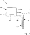
- Fig. 2 schematically shows a section through the housing 2 of the inhalation training device 1 after final assembly of the housing 2, but without microphone 5, cable 6, and the like.
- Both housing parts 2a, 2b are made preferably of molded plastic with a smoothed surface.
- handling noise caused by the patient practicing an inhalation process e.g. by sliding or scratching with his fingers over the inhalation training device 1, is reduced. Therefore, measurement accuracy is increased.
- the inhalation training device 1 provides an interface and/or is connectable to an electronic device 7.
- the electronic device 7 is a smartphone.
- the interface and/or connection to the electric device 7 is realized preferably by means of cable 6 and/or a connector 8, such as an audio jack, in particular a 3.5 mm TRRS headset connector or the like.
- the inhalation training device 1 is preferably compatible to a wide range of smartphones and is required only in one variant. This enables a comfortable and cost-efficient training of an inhalation process of a patient and a patient-friendly real-time feedback.
- the inhalation training device 1 can be connected with the electric device 7 wireless, e.g. via Bluetooth.
- the inhalation training device 1 comprises electronics 5a (indicated in Fig. 1 and 3 ) configured to process any microphone signal and/or to generate a reference tone during training.
- the reference tone accompanies the signal of the microphone 5 at all times and makes available a known reference.
- this reference tone is realized preferably by implementing a precise oscillator of a well-defined frequency of about 10 kHz and an amplitude of preferably 1.2 V into the electronics 5a of the inhalation training device 1 and mixing the reference tone into the microphone signal.
- Fig. 3 schematically shows a section through the inhaler 4 with the inhalation training device 1 attached to the mouthpiece 3 of the inhaler 4.
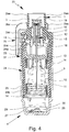
- Fig. 4 schematically shows also a section through the inhaler 4 with the inhalation training device 1 attached to the mouthpiece 3 of the inhaler 4, whereas the inhaler 4 and the attached inhalation training device 1 are axially rotated about 90°.
- the two housing parts 2a, 2b are designed preferably to exactly fit together and to firmly fit over the mouthpiece 3 of the inhaler 4. This ensures minimal leakage between the mouthpiece 3 of the inhaler 4 and the housing 2 of the inhalation training device 1. Thus, high measurement accuracy and high mechanical stability is achieved.
- the housing 2 has adequate space inside to contain and protect the microphone 5, audio cable 6 and further electronics 5a.
- the described design of the housing in particular non-circular cross-section of the section 2aa and the mouthpiece 3, prevents wrong positioning of the housing 2 when being attached to the mouthpiece 3 of the inhaler 4.
- the housing 2 is designed such that drug release during training is prevented.
- the blocking device 2c or covers 2ac, 2bc of the two housing parts 2a, 2b cover a drug release actuator, such as blocking element 15, of the inhaler 4 when the inhalation training device 1 is attached to the mouthpiece 3 of the inhaler 4.
- the microphone 5 is positioned preferably automatically, outside the mouthpiece 3 of the inhaler 4 and/or near an air-vent or opening 34 of the mouthpiece 3 of the inhaler 4.
- This enables a precise flow measurement without any need of intervention within the function of the inhaler 4 or fluid flow in the mouthpiece 3 and without the need of changing the design of the inhaler 4.
- the aerodynamic behavior of the flow path of the inhaler 4 is not changed by the inhalation training device 1. In that manner, the medical compliance of the inhaler 4 is not affected by the presence (or absence) of the inhalation training device 1.
- Measurements were taken using calibrated Tetratec flow measuring equipment and comparison was made using a stand-alone inhaler 4 and then the same inhaler 4 where the inhalation training device 1 was mounted over the mouthpiece 3 of the inhaler 4. In both situations the flow resistance was measured for a tube connected to the mouthpiece 3 (not covering the air-vents). Measurements showed that airflow is not restricted by the presence of the inhalation training device 1. The flow resistance when using the inhalation training device 1 is unchanged compared to the stand-alone inhaler 4 thereby supporting the requirements to not train patients with another type of inhalation experience.
- the inhaler 4 is designed to atomize a fluid 9, particularly a highly effective pharmaceutical composition, medicament or the like, diagrammatically shown in a non tensioned state ( Fig. 3 ) and in a tensioned state ( Fig. 4 ).
- the inhaler 4 is constructed in particular as a portable inhaler and preferably operates only mechanical and/or without propellant gas.
- the inhaler 4 is provided with or comprises an insertable or replaceable container 10 containing the fluid 9.
- the container 10 thus forms a reservoir for the fluid 9, which is to be nebulized.
- the container 10 contains multiple doses of fluid 9 or active substance in particular sufficient to provide up to 200 dosage units or doses, for example, i.e. to allow up to 200 sprays or applications.
- a typical container 10, as disclosed in WO 96/06011 A1 holds e.g. a volume of about 2 to 20 ml.
- the dose can vary, in particular depending on the fluid 9 or medicament.
- the inhaler 4 can be adapted respectively.
- the number of doses contained in the container 10 and/or the total volume of the fluid 9 contained in the container 10 can vary depending on the fluid 9 or respective medicament and/or depending on the container 10 and/or depending on the necessary medication or the like.
- the container 10 can be replaced or exchanged, wherein the number of containers 10, which can be used with the same inhaler 4, is preferably restricted, e.g. to a total number of four or five containers 10.
- the container 10 is preferably substantially cylindrical or cartridge-shaped and once the inhaler 4 has been opened the container 10 can be inserted therein preferably from below and changed if desired. It is preferably of rigid construction, the fluid 9 in particular being held in a collapsible bag 11 in the container 10.
- the container 10 comprises a venting opening or hole 30 which is opened before or during first use.
- the inhaler 4 comprises a delivery mechanism, preferably a pressure generator 12, for conveying and nebulizing the fluid 9, particularly in a preset and optionally in an adjustable dosage amount.
- the inhaler 4 or pressure generator 12 comprises preferably a holder 13 for releasably holding the container 10, a drive spring 14 associated to the holder 13, only partly shown, and/or a blocking element 15 preferably in form of or with a button for preferably manual actuation or depressing.
- the blocking element 15 can catch and block the holder 13 and can be manually operated to release the holder 13 allowing drive spring 14 to expand.
- the inhaler 4 or pressure generator 12 comprises preferably a conveying element, such as a conveying tube 16, a non-return valve 17, a pressure chamber 18 and/or a nozzle 19 for nebulizing the fluid 9 into the mouthpiece 3.
- a conveying element such as a conveying tube 16, a non-return valve 17, a pressure chamber 18 and/or a nozzle 19 for nebulizing the fluid 9 into the mouthpiece 3.
- the completely inserted container 10 is fixed or held in the inhaler 4 via the holder 13 such that the conveying element fluidically connects the container 10 to the inhaler 4 or pressure generator 12.
- the conveying tube 16 penetrates into the container 10.
- the inhaler 4 or holder 13 is preferably constructed so that the container 10 can be exchanged.
- the inhaler 4 operates with a spring pressure of 5 to 200 MPa, preferably 10 to 100 MPa on the fluid 2, and/or with a volume of fluid 2 delivered per stroke of 10 to 50 ⁇ l, preferably 10 to 20 ⁇ l, most preferably about 15 ⁇ l.
- the fluid 9 is converted into or nebulized as aerosol, the droplets of which have an aerodynamic diameter of up to 20 ⁇ m, preferably 3 to 10 ⁇ m.
- the generated jet spray has an angle of 20° to 160°, preferably 80° to 100°.
- the inhaler 4 comprises preferably a housing 31 and/or (upper) housing part 23 and optionally a biasing or inner part 24 preferably which is rotatable relative thereto ( Fig. 4 ) and/or has an upper part 24a and a lower part 24b ( Fig. 3 ).
- the inhaler 4 or housing 31 comprises preferably a (lower) housing part 25.
- This part 25 is in particular manually operable, and/or releasable fixed, particularly fitted or held onto the inner part 24, preferably by means of a retaining element 26.
- the housing parts 23 and 25 and/or other parts form the housing 31 of the inhaler 4.
- the housing 31 can be opened and/or the housing part 25 can be detached from the inhaler 4, inner part 24 or housing 31.
- the container 10 can be inserted before the housing 31 is closed and/or before the housing part 25 is connected to the housing 31.
- the container 10 is inserted, opened and/or fluidically connected to the delivery mechanism automatically or simultaneously when (completely) connecting the housing part 25 to the housing 31 / inhaler 4 and/or when (completely) closing the housing 31 / inhaler 4.
- the inhaler 4 or drive spring 14 can be manually activated or tensioned, in particular by actuation of an actuation member, here preferably by rotating housing part 25 or any other component.
- the actuation member preferably the housing part 25, can be actuated, here rotated relative to the upper housing part 23, carrying with it or driving the inner part 24.
- the inner part 24 acts on a gear or transmission to transform the rotation in an axial movement.
- the drive spring 14 is tensioned in the axial direction by means of the gear or transmission (not shown) formed between the inner part 24, in particular its upper part 24a, and the holder 13 and acting on the holder 13.
- the drive spring 14 is under tension and can be caught or held by the blocking element 15.
- the container 10 is moved back into its original position (non-tensioned position or state shown in Fig. 3 ) by (the force of) the drive spring 14.
- the container 10 executes a lifting or stroke movement during the tensioning process and during the nebulizing process.
- the housing part 25 preferably forms a cap-like lower housing part and/or fits around or over a lower free end portion of the container 10.
- an aeration means such as an axially acting spring 27 arranged in the housing part 25, comes in contact with base 28 of the container 10 and pierces the container 3 or a base seal or foil 50 thereon with a piercing element 22 when the container 3 makes contact with it for the first time, to allow air in or aeration, preferably by opening or piercing venting hole 23.
- the inhaler 4 comprises preferably an indicator device 25, which counts in particular actuations of the inhaler 4, preferably by detecting its tensioning or the rotation of the inner part 24 relative to the upper part 23 or housing 31.
- the counter device 32 or an associated locking device 33 locks the inhaler 4 against (further) actuation or use, e.g. blocks further rotation of the housing part 25 / inner part 24 and, thus, tensioning of the inhaler 4 or its drive spring 14 and/or blocks actuation of the blocking element 15, in a locked state when a certain number of actuations or operations or discharged doses has been reached or exceeded.
- the inhaler 4 is preferably designed to be portable and in particular is a mobile hand operated device.
- the fluid 9 is an aqueous pharmaceutical formulation or an ethanolic pharmaceutical formulation.
- it may also be some other pharmaceutical formulation, a suspension or the like.
- the fluid 9 may also comprise particles or powder.
- some other kind of supply device may be provided, especially an expulsion opening (not shown) or a supply channel (not shown) for supplying the fluid to or powder or the like into the mouthpiece 3.
- An optional air supply opening (not shown) then serves to supply ambient air preferably in parallel so as to general or allow an airflow with a sufficient volume for breathing in or inhaling through the mouthpiece 3.
- the fluid 9 may also be atomized by means of a propellant gas.
- Preferred ingredients and/or formulations of the preferably medicinal fluid 9 are listed in particular in WO 2009/115200 A1 , preferably on pages 25 to 40, or in EP 2 614 848 A1 , paragraphs 0040 to 0087. In particular, these may be aqueous or non aqueous solutions, mixtures, formulations containing ethanol or free from any solvent, or the like.
- Fig. 5 schematically shows a perspective view of a preferred embodiment of an inhalation training system 35 according to the present invention.
- the inhalation training system 35 is used or usable or designed for practicing of an inhalation process of a patient.
- the inhalation training system 35 comprises the inhalation training device 1 as described above, an inhaler 4 preferably as described above, and a separate and/or mobile electronic device 7, preferably a smartphone.
- the smartphone 7 is configured for evaluation of a signal received from the inhalation training device 1 and for visual and/or audio feedback to the patient, in particular via a display 7a, a loud speaker 7b or the like.
- the purpose of the inhalation training system 35 is to further educate the patient to inhale correctly with the range of inhalers. Due to the preferred soft mist technology of the inhalers which generate a homogeneous droplet aerosol cloud of 1 to 1.5 seconds duration and where the instructions for correct inhalation is to inhale with relative low flow over an extended period of time, some patients may potentially be confused on correct use as they previously might have been subjected to other inhalers specifically requiring them to inhale forcefully and with only very short duration (e.g. passive dry powder inhalers).
- the inhalation training system 35 enables an effective, simple, reliable, comfortable and cost-efficient training of an inhalation process of a patient and a precise measurement of a flow generated by the patient during training and a patient-friendly real-time feedback.
- the inhalation training system 35 is configured to non-invasive detection (i.e. with unchanged flow resistance of the inhaler 4) of correct inhalation flow in the range of at least 20 to 40 l/min with an accuracy of at least +/- 50 % but preferably better than +/- 20 %.
- the electronic device 7 is configured preferably to detect the presence of the inhalation training device 1 by means of the reference tone generated by the inhalation training device 1 during training as described above. Thus, the electronic device 7 can detect if an inhalation training device 1 has been plugged via connector 8 into the electronic device 7. The electronic device 7 is configured to not provide any feedback related to flow detection if this is not the case.
- the electronic device 7 is capable of interfacing to the external microphone 5 of the inhalation training device 1.
- the electronic device 7 is equipped with a dedicated App which in combination is capable of real-time measuring and displaying information (preferably via display 7a) related to patient inhalation flow thereby providing feedback regarding correct and incorrect inhalation techniques.
- the App presents flow feedback to the patient in a simple and intuitive manner (non-scientific) and is available for download onto the electronic device 7.
- the App is developed for all main platforms, especially iOS and Android.
- the App and/or electronic device 7 are adapted to give an audible and/or visible feedback, preferably via the display 7a of the electronic device 7 and/or most preferably by showing one or more respective symbols 7, such as a balloon or the like, which can be easily understood by most people (compare Fig. 5 which shows as an example a balloon as symbol 7d for indicating the inhalation process or the like).
- a balloon concept was finally chosen as the core element to provide feedback regarding patient inhalation flow pattern.
- the patient's inhalation flow rate determines the balloon flight level. If the patent performs a forceful inhalation (e.g. more than 60 l/min) the balloon will fly high on the screen, whereas a very weak inhalation (e.g. less than 10 l/min) will result in the balloon hovering at the bottom of the screen. In the center range of 20-40 l/min the balloon shifts color from red (amber) to green and two sharp arrows start to close in from the sides. After two seconds of correct flow rate the arrows puncture the balloon thereby indicating a successful inhalation. When the balloon pops the screen turns to a 10 seconds countdown clock allowing training of breath holding following inhalation (similar to the use instructions).
- the App is split in two parts, a passive guide part and an active training part, and the patient is carefully introduced to the guide before being subject to real training.
- the patient initially accepts the terms of use and then enters into the guide part of the App where he is carried through all patient related installation steps of mounting the inhalation training device 1 over the mouthpiece 3 of the inhaler 4 and plugging the connector 8 into the electronic device 7.
- the patient is introduced to the features of the App using animated screens of both balloon flying and breath holding.
- the patient may press a highlighted 'X' to exit the guide and begin training, otherwise he will on the very last guide page be redirected to the training part of the App by simple button confirmation to 'Start training'.
- the App requires the presence of the inhalation training device 1 to function. If the inhalation training device 1 is not mounted then a warning will be presented to the patient.
- the user or patient could also press a button 7c, the touch screen or the like of the electronic device 7 for input or confirmation purposes.
- the flow training takes place by inhaling through the inhalation training device 1 mounted over the inhaler 4 and completing the quest to balance the balloon in the 'green' zone for two seconds and following to hold the breath for 10 seconds.
- the green colored symbol will fly into a history bar showing the last five attempts. Since the App has no means to detect the patient holding the breath the last step in this training sequence will never be able to disqualify an otherwise perfect inhalation sequence only the final result adding to the history awaits the 10 seconds wait.
- the primary training objective of the inhalation training device 1 is to help patients reduce inhalation flow to a much lower level than e.g. required with a passive DPI the one element that can cause an unsuccessful inhalation is if the patient inhales too strongly (above 40 l/min) for two seconds (or longer). In this situation the inhalation sequence will be unsuccessful and the negative result will be added directly to the history without going through the sequence of breath holding.
- Instructions are preferably stored on an information storage medium and when executed by a processor cause the execution of the steps described above.
- Flow measurement accuracy also depends on the production tolerances of the microphone 5 which potentially could exhibit +/- 3 dB variation in acoustic sensitivity. If no other sources to error did exist such microphone tolerance variation would translate to a measuring uncertainty around +/- 35 %. This uncertainty does not appear to be critical to perform the inhalation training process where e.g. a measuring uncertainty of +/- 50 % has been communicated being acceptable.
- the microphone gain and/or the reference tone amplitude can be calibrated.
- each electronics module including the microphone 5 is subjected (prior to mounting in the housing 2 of the inhalation training device 1) to a test using a reference acoustic signal allowing assessment of variation from ideal reference.
- the reference tone amplitude is adjusted to produce the desired relation to the measured microphone signal. Adjustment could be as simple as cutting a wire on the carrying flexible printed circuitry board (cutting e.g. a parallel resistor controlling reference voltage attenuation).
- the final assembled inhalation training device 1 could be tested to create a code based on the individual acoustic deviation.
- the code can then be imported into the App prior to use.
- the inhalation training device 1 can have an individual serial number containing a single digit reference to categorize the inhalation training device 1.
- a barcode can be printed on the housing 2 of the inhalation training device 1. The patient can then scan the barcode with a camera of the smartphone 7 during the initialization procedure of the App.
- the inhalation training device or its housing 2 comprises the blocking device 2c for blocking any dispensing of fluid 9 by the inhaler 4 when the inhalation training device 1 is mounted to or with the inhaler 4.
- the blocking device 2c covers an actuation element or button, such as blocking element 15 of the inhaler 4 in order to block or prevent any possible actuation and, thus, any possible dispensing of fluid 9.
- other construction solutions are possible as well.
- the inhalation training device 1 does not (significantly) amend or restrict the flow of air which is drawn through the at least one opening 34 into the mouthpiece 3 during inhalation.
- the microphone 5 might protrude into an associated opening 34 and/or is preferably located adjacent, most preferably as near as possible, to one venting opening 34.
- the inhalation training device 1 or its housing 2 does not cover the other opening 34.
- the inhalation training device 1 or housing 2 comprises preferably a recess 2d as indicated in Fig. 1 to 3 .
- the inhalation training device 1 or its housing 2 comprises preferably at least one supply opening 2e or the like as schematically shown in Figs. 1 and 3 .
- the cable 6 is guided within the inhalation training device 1 or its housing 2 from the mouthpiece 3 towards the other end of the inhaler 4, preferably through the blocking device 2c and/or preferably thinner like portions or sections 2ac and/or 2bc.
- the microphone 5 and electronics 5a form a unit or assembly.
- the electronics 5a is integrated into the microphone 5 or vice versa.
- the training inhalation device 1 or its housing 2 holds the unit or assembly of microphone 5 and/or electronics 5a by snap-fit and/or form-fit.
- a possible realization is indicated in Fig. 3 schematically.
- the unit or assembly can be inserted into or through a holding recess 2f or the like or mounted, with the microphone 5 preferably pointing towards the mouthpiece 3, adjacent to air vent opening 34 and/or adjacent to the nozzle 19 of the inhaler 4 and/or pointing radially inwards.
- the blocking device 2c is supported or abuts against the inhaler housing 31, preferably an upper housing part 23 of the inhaler 4.
- the blocking device 2c or section 2ac may comprise a respective protrusion or contact portion 2ca as indicated in Figs. 4 and 5 .
- the blocking device 2c covers the blocking element 15 or any other actuation element, necessary for triggering or initiating dispensing of fluid 9 from the nebulizer 4, preferably completely, such that any dispensing of fluid 9 from the inhaler 4 is securely prevented when the inhalation training device 1 is mounted to the inhaler 4 or vice versa.
Landscapes
- Health & Medical Sciences (AREA)
- Life Sciences & Earth Sciences (AREA)
- General Health & Medical Sciences (AREA)
- Engineering & Computer Science (AREA)
- Pulmonology (AREA)
- Animal Behavior & Ethology (AREA)
- Public Health (AREA)
- Veterinary Medicine (AREA)
- Biomedical Technology (AREA)
- Heart & Thoracic Surgery (AREA)
- Biophysics (AREA)
- Physical Education & Sports Medicine (AREA)
- Hematology (AREA)
- Anesthesiology (AREA)
- Bioinformatics & Cheminformatics (AREA)
- Orthopedic Medicine & Surgery (AREA)
- Surgery (AREA)
- Physiology (AREA)
- Physics & Mathematics (AREA)
- Pathology (AREA)
- Medical Informatics (AREA)
- Molecular Biology (AREA)
- Mechanical Engineering (AREA)
- Measurement Of The Respiration, Hearing Ability, Form, And Blood Characteristics Of Living Organisms (AREA)
- Instructional Devices (AREA)
- Percussion Or Vibration Massage (AREA)
Description
- This invention relates to an inhalation training device for practicing of an inhalation process of a patient according to the preamble of
claim 1, and to an inhalation training system for practicing of an inhalation process of a patient. - Drugs which are to be inhaled constitute a preferred therapy for patients with asthma, a chronically obstructive pulmonary disease or other chronic or acute conditions or diseases of the respiratory tract.
- So-called inhalers are used for inhalation of drugs. The most frequently used inhalers are pressurized metered-dose inhalers (pMDls) and dry powder inhalers (DPIs). pMDIs were developed to supply a precise amount or dose of a drug in the form of a cloud of aerosol droplets to the lungs of the patient when the latter inhales. Dry powder inhalers are made such that when the patient inhales they supply a metered amount of dry pulverized particles to the lungs.
- An alternative inhaler is shown e.g. in
WO 2008/151796 A1 . This inhaler delivers a metered dose of medication as a slow-moving, soft mist through a nozzle system without use of any propellant. - The effectiveness of drugs which are to be inhaled depends largely on the way the inhaler is used by the patient. Optimally, the correct amount of the drug travels to the desired regions of the lungs at the correct instant of time. Otherwise, the therapeutic effect is reduced and/or the risk of contrary effects is increased.
- The literature contains numerous instances substantiating that many patients incorrectly use inhalers. Instruction of the patient with respect to a correct inhalation technique can improve the use of inhalers. In addition to written and oral instructions, practical exercises are helpful for this purpose.
- Since inhalation generally proceeds subconsciously and develops over the course of a lifetime, it is however especially difficult for a patient to change his inhalation in order to increase the effectiveness of a drug which is to be inhaled. Rather, it is known that many patients again use suboptimum inhalation even a short time after instruction. Therefore repeated, preferably regular practicing (in particular used as synonym for training) of inhalation and its checking are recommended.
- Inhalation training systems were developed for this purpose. Known inhalation training systems differ among others with respect to the inhalation model for which the patient is to be trained, with respect to the type of feedback to the patient (for example acoustically or visually), with respect to the measured variable (for example inhaled volume, volumetric flow or flow rate or mass flow which is produced during inhalation, velocity of the inhaled particles during the inhalation process), with respect to sensors and actuators (for example mechanical, magnetic or electronic) and with respect to size, handling and costs. Some inhalation training systems use inhalers which are available on the market, while other inhalation training systems copy or emulate inhalers or parts of them.
-
EP 1 993 642 A1 -
US 2009/314292 A1 , which forms the starting point of this invention, discloses an interactive apparatus and method for sensing and measuring real-time characteristic patterns of a subject's use of a dry powder inhaler. The devices can be used in a wired or wireless communication mode to communicate with a display to assess the subject's usage of the inhalation system, to evaluate the performance of the inhalation system and/or to detect the characteristics profile of a dry powder formulation emitted from the inhalation system in use. - The apparatus can include a detachable sensing and monitoring device, which can be used as needed by a patient or a health provider in training or gathering information from the patient's inhalation maneuvers and then removed from the dry powder inhaler. The detachable sensing and monitoring device can be adapted to a mouthpiece of the dry powder inhaler.
- The apparatus can comprise a sensor, for example a microphone, positioned in the air pathway of the mouthpiece. The sensor can alternatively be positioned within the sensing and monitoring device.
- Object of the present invention is to provide an inhalation training device and an inhalation training system enabling an effective, simple, reliable, comfortable and/or cost-efficient training of an inhalation process of a patient and/or a simple, cost-efficient, robust and/or regulatory compliant structure and/or a precise measurement of a flow generated by the patient during training and/or a patient-friendly real-time feedback.
- The above object is achieved by an inhalation training device as claimed in
claim 1 or by an inhalation training system as claimed inclaim 10. Preferred embodiments of the invention are subject of the dependent claims. - According to the present invention, the microphone is positioned near an air-vent of the mouthpiece of the inhaler, when the inhalation training device is attached to the mouthpiece of the inhaler. This enables a precise flow measurement without any need of intervention within the function of the inhaler and without the need of changing the design of the inhaler. This embodiment does not change the aerodynamic behavior of the flow path of the inhaler. In that manner, the medical compliance of the inhaler is not affected by the presence (or absence) of the inhalation training device.
- Preferably, the housing comprises a pad and/or a sleeve around the microphone, in particular made of foam plastic or soft silicone. Thus, insulation of the microphone is improved and vibrations coupling from the inhalation training device into the microphone are reduced. This will further reduce handling noise and improve flow measurement accuracy.
- Preferably, the microphone is an electret microphone.
- Preferably, the microphone is adapted to measure the noise of the airflow through the air-vent of the mouthpiece of the inhaler. It is well known from acoustics that sound travels well in most solid materials. When a patient inhales using the inhaler, the flow path within the inhaler creates a characteristic flow noise sound depending on flow rate and turbulences. Some of this sound is transmitted through the solid structure of the inhaler. As losses in the solid material are small, it is in principle possible to detect the sound anywhere on the inhaler surface. The preferred embodiment of measuring the noise of the airflow through the air-vent of the mouthpiece of the inhaler enables an effective and reliable training and a precise flow measurement during training.
- Preferably, the microphone exhibits directionality, in particular a cardioid, super-cardioid, hyper-cardioid or a bi-directional characteristic. The directional microphone characteristic allows for the microphone itself cancelling out signals that originate from outside the mouthpiece of the inhaler, however not affecting sounds that originate from within. Thus, influence from ambient noise during training can be reduced and flow measurement accuracy can be increased.
- Preferably, the inhalation training device provides an interface to an electronic device. The electronic device preferably is a portable communications device capable of capturing, transmitting and/or outputting information and which can be easily transported by an individual. Typical applications of portable communications devices are telephony, data transmission, games, text processing, table processing, image processing, photography and music playback. Typical examples of portable communications devices are mobile phones, smartphones, tablet PCs, handhelds and PDAs.
- This embodiment enables exploitation of the functionality of the electronic device, especially for processing and/or evaluation of the signal measured by the microphone of the inhalation training device and/or for feedback to the patient and/or a third party in a simple, intuitive, reliable and cost-efficient manner. At the same time, this embodiment enables expansion of the functionality of the electronic device in a simple and cost-efficient manner with respect to practicing of an inhalation process of a patient.
- As a result of the popularity of portable communications devices, access to inhalation training can also be provided to patients who would not like to buy a special electronic device only for inhalation training. Since the owners of portable communications devices are accustomed to their handling, the embodiment as claimed in the invention also enables easier and faster learning of an optimum inhalation process. Since many individuals continually carry a portable communications device, the embodiment as claimed in the invention can also lead to more frequent, possibly regular inhalation training. Furthermore, the embodiment as claimed in the invention increases the ease of operation and the portability of inhalation training.
- In particular, the interface to the electronic device is realized by means of an audio jack, especially a 3.5 mm TRRS headset connector. Audio jack is a generic term for a family of connectors typically used for analog audio signals. An audio jack typically has a cylindrical shape, typically with two, three or four contacts. Four-contact versions are known as TRRS connectors, where T stands for "tip", R stands for "ring" and S stands for "sleeve". Modern audio jacks are available in three standard sizes, i.e. 6.35 mm, 3.5 mm and 2.5 mm.
- As the 3.5 mm TRRS headset connector is the globally most common connector for portable communications devices, the proposed embodiment ensures that the inhalation training device is compatible to a wide range of portable communication devices and is required only in one variant. Thus, the proposed embodiment enables a comfortable and cost-efficient training of an inhalation process of a patient and a patient-friendly real-time feedback.
- However, even if manufacturers have agreed on the physical format for the 3.5 mm TRRS headset connector, they disagree on various details associated with the electronic interfacing. One of the most fundamental differences is the polarity of the microphone connections, which e.g. differ between the family of Apple devices compared to most other manufacturers, e.g. Samsung, HTC, LG, Sony, Motorola, Microsoft, Blackberry and Nokia. The typical connection schemes are given by the following table.
Apple Other manufacturers Tip Left audio Left audio Ring Right audio Right audio Ring Ground Microphone Sleeve Microphone Ground - Preferably, the inhalation training device comprises electronics configured to swap the electric connection to the microphone and to ground in dependence of the connection scheme of the TRRS headset connector. In particular, the differing polarity of the microphone connections are handled automatically using analog electronic switches placed in the connection between the microphone and the TRRS headset connector. Especially, the microphone bias voltage (i.e. the positive voltage on the microphone connection) is used directly to select the relevant switching and both the microphone and the ground connections will hence be swapped as necessary. Such analog switching provides excellent audio properties and very limited resistance down to well below 1 Ohm.
- Besides the polarity of the microphone connections there also exist minor differences in how and when a specific portable communications device recognizes that an external connection is established, related to the impedance level between the microphone and ground connectors.
- Preferably, the inhalation training device comprises electronics configured to adjust the frequency range in which the microphone operates as a function of the analog front-end sensitivity of the electronic device. The flow-induced noise measured by the microphone of the inhalation training device is to be analyzed to assess the airflow and typically this means to convert the sound pressure level (e.g. in selected frequency bands) to a sound pressure level and then use established correlation patterns between noise and flow to determine the appropriate flow level. This however assumes well-specified audio properties of the electronic device, in particular the analog front-end sensitivity but also linearity and (for wide band signals) frequency range and linearity.
- In order to handle speech in high quality, electronic devices typically filter a frequency range from 200 Hz to 20000 Hz. From the perspective of the inhalation training device, turbulent flow noise will generally have a wide-band noise profile covering at least the frequencies from 100 Hz to 10000 Hz, but typically the flow signal is carried well within narrow bands, e.g. 500 Hz to 1000 Hz (dependent on the inhaler type among others). The preferred embodiment of the inhalation training device therefore allows for adjusting the frequency range in which the microphone operates depending on the audio properties of the electronic device, in particular, its analog front-end sensitivity.
- With respect to the amplitude linearity, the inhalation training device preferably targets the typical speech range of amplitudes in order to be less prone to potential (unknown) compression. The electronics of the inhalation training device is, however, tunable to stay in the linear region of the most restrictive electronic device thereby ensuring an adequate uniform electronics interface to all selected electronic devices.
- Preferably, the inhalation training device comprises electronics configured to generate a reference tone during training. Thus, the reference tone accompanies the microphone signal to at all times make available a known reference. This reference tone can be realized by implementing a precise oscillator of a well-defined frequency (e.g. 10 kHz) and amplitude into the electronics of the inhalation training device and mixing the reference tone into the microphone signal.
- Preferably, the oscillator for the reference tone is build up around a low voltage operational amplifier and a precision voltage controller which defines an amplitude of 1.2 V.
- Preferably, the housing of the inhalation training device is designed to prevent wrong positioning (e.g. up/down and/or right/left rotation from correct position) of the housing when being attached to the mouthpiece of the inhaler.
- According to the present invention, the housing is designed to prevent drug release and/or dispensing of any fluid during training. In particular, parts of the housing of the inhalation device cover the drug release actuator of the inhaler when the inhalation training device is attached to the mouthpiece of the inhaler. This embodiment ensures that the inhalation training device complies with regulatory requirements, e.g. the EU Medical Device Directive (MDD/93/42/EEC) and the US Medical Device guidelines (FDA 21 CFR Part 820).
- Optionally, the housing of the inhalation training device consists of two housing parts snap-clicked together during assembly of the housing. The two housing parts are two simple mechanical parts designed to fit over the mouthpiece of the inhaler. Thus, a robust and cost-efficient unit is created that sits firmly over the mouthpiece, with shortest possible tolerance chain thereby ensuring best possible performance with regards to precise microphone position, with regards to minimal leakage between the mouthpiece of the inhaler and the housing of the inhalation training device thereby supporting the measuring accuracy and finally with regards to mechanical stability. Furthermore, the housing has adequate space inside to contain and protect the microphone, further electronics and cables.
- The inhalation training device as claimed in the invention enables effective, comfortable and reliable practicing of an inhalation process.
- Preferably, both housing parts are made of molded plastic, in particular acrylonitrile butadiene styrene (ABS), with a smoothed surface. This embodiment enables a cost-efficient structure and a reduction of handling noise caused by the patient practicing an inhalation process, e.g. by sliding or scratching with his fingers over the inhalation training device. Therefore, this embodiment enables a higher measurement accuracy.
- The measurement accuracy can be increased further by coating both housing parts at least partially with a low-friction layer, in particular glossy chrome. It was found that as much as 15 dB of friction noise difference may exist between a smooth ABS surface and the same surface coated with glossy chrome.
- Preferably, the housing comprises molded parting lines for sealed fit with the mouthpiece of the inhaler. This embodiment enables a reliable training of an inhalation process, a robust structure and a precise flow measurement.
- Another aspect of the present invention relates to an inhalation training system for practicing of an inhalation process of a patient. According to this aspect, the inhalation training system comprises an inhalation training device according to one or more of the preceding aspects, an inhaler and an electronic device configured for evaluation of a signal received from the inhalation training device and for visual and/or audio feedback to the patient.
- This inhalation training system enables an effective, simple, reliable, comfortable and cost-efficient training of an inhalation process of a patient and a precise measurement of a flow generated by the patient during training and a patient-friendly real-time feedback.
- Preferably, the inhalation training system is configured to detect the presence of exhalation of the patient during training. When the patient should accidentally exhale into the mouthpiece of the inhaler during training, this can wrongfully reinforce an incorrect or inefficient patient behavior. Therefore, detecting the presence of exhalation of the patient during training enables an effective training of an inhalation process of the patient.
- Measurements of either inhalation or exhalation flow and then extraction of the frequency spectra for each individual flow level, separately for inhalation and exhalation, showed that generally the inhalation flow produces flatter spectral responses compared to exhalation flow. This means that when calculating the ratio between the low frequency versus high frequency energy contents then exhalation produces a greater ratio than would inhalation. The inhalation training system exploits this relationship by defining a suitable threshold separating these two frequency clusters. For example, the low frequency signal content is assessed using as a 300 Hz filter whereas the high frequency signal content is assessed using a 7000 Hz filter and a threshold of 70 has been identified to provide good separation between inhalation and exhalation for low flow rates of approximately 10-30 l/min.
- Towards higher flow rates, however, the spectral curves for inhalation and exhalation respectively tend to look more and more alike meaning that this separation will not have sensitivity for high flow rates. To handle this situation, another cue is employed based on another characteristic tendency for the above flow sound spectra, namely that the exhalation sound spectra tend to reach higher levels in the low frequency region than does the complementary inhalation sound spectra. Based on this observation, an additional indicator for presence of exhalation flow is the low frequency signal energy. Preferably, the inhalation training system decides on having detected an exhalation if the low frequency signal energy exceeds a threshold of 7. This threshold provides adequate separation between the inhalation and exhalation for high flow rates of approximately 50-90 l/min.
- The definition of the preferred thresholds has been made with a clear ambition to have a high degree of detection specificity, i.e. the inhalation training system should not give a warning of exhalation while the patient is actually inhaling correctly.
- Preferably, the electronic device is configured to detect the presence of a characteristic voice signal in the signal received from the inhalation training device. Human voice typically does not have a flat sound spectrum but rather consist of an equally spaced train of peaks and valleys starting with the lowest formant frequency. The electronic device can be configured to cease flow evaluation temporarily if the signal received from the inhalation training device is dominated by such a characteristic voice signal or spectrum. Thus, robustness against the influence of voice is improved.
- Preferably, the electronic device is configured to detect the presence of the inhalation training device and/or a specific type of the inhaler, in particular by means of a reference tone generated by the inhalation training device during training. For this purpose, the reference tone generated by the inhalation training device as described above can be utilized, especially for automated robust detection that an inhalation training device as claimed has been plugged via the interface (3.5 mm TRRS headset connector) into the electronic device. The electronic device can be configured to not provide any feedback related to flow detection if this is not the case.
- The electronic device preferably is a portable communications device capable of capturing, transmitting and/or outputting information and which can be easily transported by an individual. Typical examples of portable communications devices are mobile phones, smartphones, tablet PCs, handhelds and PDAs. The electronic device within the scope of this invention is a device which is separate or independent of the inhalation training device.
- Preferably, the electronic device is designed for storage, output and/or interactive feedback of a measured, processed and/or evaluated signal to the patient and/or a third party. In particular, the electronic device has a device for acoustic feedback of the evaluation, for example, a speaker, and/or for visual feedback of the evaluation, for example a screen.
- The electronic device can in particular provide instructions for correct inhalation and/or advice for optimization. For more effective training of the patient the electronic device can additionally display pictures and/or videos which illustrate an optimum inhalation process.
- The term "interactivity" designates the properties of making available to the patient intervention and control possibilities for individualized learning. To do this, for example, the choice and the type of representation of information can be adapted to prior knowledge, the interests and needs of the patient or can be manipulated by him. Solely making available information does not constitute interactive feedback for the purposes of this invention.
- Preferably, the electronic device is designed for wireless transmission of a measured, processed and/or evaluated signal to another electronic device. In this way, the signal can be transmitted, for example, to a physician who on this basis can prepare a diagnosis and/or can give advice for improving the inhalation process.
- Preferably, the electronic device is designed or can be used for practicing an effective inhalation time Tin, eff which is as optimum as possible. In this way, the patient is enabled to achieve an effective inhalation time as optimum as possible. The effective inhalation time is the time during an inhalation of an inhalation training process, especially the time of simulated inspiration, in which the delivery of an amount or dose of a drug is simulated. In particular, the effective inhalation time is the portion of time in which the inhalation and the simulated delivery of the dose of drug overlap.
- Based on the effective inhalation time an inhaled dose of drug (iDoD) can be estimated. This applies especially when the drug is typically delivered at a constant rate. The inhaled dose of drug can be given as a percentage of the delivered dose of drug. The effective inhalation time and the inhaled dose of drug are indicative with respect to the quality of the inhalation process.
- To practice the effective inhalation time the electronic device is preferably designed for determination of the effective inhalation time. To determine the effective inhalation time the electronic device can determine a delivery time or spray time. The delivery time or spray time is the time during which a delivery of a dose of drug is simulated. The end of delivery is preferably fixed by a fixed delivery duration or spray duration (SDur). Preferably, the effective inhalation time is given in a percentage of the spray duration.
- In one preferred embodiment, the effective inhalation time is 0% when the delivery time is outside the time of the inhalation process or of inhalation (Tin), i.e. when the delivery time has passed before the start of the inhalation process. In this embodiment, the effective inhalation time is 100% when the delivery time is completely within the time of the inhalation process.
- If the delivery begins before the start of the inhalation process and the delivery ends after the end of the inhalation process, the effective inhalation time is determined preferably according to the following formula:

- If the delivery starts after the start and before the end of the inhalation process and the delivery ends after the end of the inhalation process, the effective inhalation process is preferably determined according to the following formula:

- Δ being the difference between the start of the delivery and start of the inhalation process, i.e. Δ has a positive value when the delivery starts after the start of the inhalation process and Δ is a negative value when the delivery starts before the start of the inhalation process.
- If the delivery starts before the beginning of the inhalation process and the delivery ends after the start and before the end of the inhalation process, the effective inhalation process is preferably determined according to the following formula:

- Δ being the difference between the start of the delivery and start of the inhalation process.
- In particular, when determining the effective inhalation time solely the inspiration times can be considered as the inhalation time Tin. If therefore inspiration is interrupted by holding the breath or expiration, these times are preferably subtracted from the inhalation time.
- Alternatively or in addition, the electronic device can be designed for determination or estimation of a volumetric flow or flow rate which has been generated in the inhalation process and/or a flow velocity generated here. These two physical quantities are highly indicative with respect to the quality of the inhalation process.
- The electronic device can also be designed for determination or estimation of the flow velocity. It has been found that depending on where the drug is to be deposited (throat, lungs), the velocity of the inhaled drug must be different. Thus, the flow velocity may be of interest in the determination whether the inhalation was correct. The electronic device can also be designed for determination or estimation of the time during which the flow was within a certain flow velocity interval or above a certain lower limit, again to ensure that the inhalation was correct or sufficient.
- Preferably, practicing of inhalation is carried out with support by software which is matched to the electronic device and can be ordered in particular via an online portal and installed. Typically, this software is called an "App". The use of an App improves the flexibility and ease of operation.
- The App can be used, for example, for processing and interpretation of the measured signal and for feedback to the patient and/or a third party. To do this, the App can be made available or executed using an information storage medium. The information storage medium is preferably made for use in a portable communications device, especially optimized with respect to the space requirement, energy consumption, reliability and data transmission rate.
- Preferred steps of the App are described below.
- In the preferred steps of the App, the App is started in a first step. In a later step a graphic user interface (GUI) is initiated and preferably displayed on a screen of the electronic device. In particular, a visual start indication or visual trigger indication is also displayed.
- In another step a loop function is started using which the GUI is updated in order to display for example altered contents of the GUI.
- Preferably the start indication or trigger indication is evaluated using the App. In particular, an input of the user or patient, quite especially the actuation of the start indication or of the trigger indication by the user or patient, is monitored. The monitoring of the input leads preferably to a decision whether the start indication or trigger indication has been actuated. If it is decided that an actuation of the start indication or trigger indication has taken place, preferably two parallel branches are followed by the App.
- On the one hand, in a first branch it is preferably monitored whether a visual stop indication (especially on the screen) is actuated. This monitoring leads preferably to a decision whether the stop indication has been actuated. On the other hand, in a second branch parallel to the monitoring of the stop indication an electrical signal value or several electrical signal values of the inhalation training device is or are read out. Preferably the App or the electronic device induces processing of the electrical signal values, especially digitization and storage of the electrical signal values.
- In another step in the second branch a volumetric flow or flow rate which has been produced in the inhalation process is determined and/or a flow rate profile is prepared using the App or the electronic device.
- Within the second branch preferably the starting of an inhalation process is monitored by the App or the electronic device. Monitoring leads preferably to a decision whether the inhalation process has been started. Here the App or the electronic device is preferably designed such that an actuation of the trigger indication is interpreted as starting of an inhalation process; this leads to the decision that the inhalation process has started.
- If it is decided that an inhalation process has started, on the one hand preferably a starting time is determined by the App or the electronic device. In addition, preferably further time values can be determined by the App or the electronic device via time keepers.
- If it is decided that an inhalation process has started, on the other hand preferably the ending of the inhalation process is monitored by the App or the electronic device. The monitoring leads preferably to a decision whether the inhalation process has ended. Here the App or the electronic device is preferably designed such that a repeated actuation of the trigger indication or an actuation of the ending indication (especially on the screen) is interpreted as ending of the inhalation process; this leads to the decision that the inhalation process has ended.
- If it is decided that the inhalation process has ended, preferably a stop time is determined by the App or the electronic device.
- If the monitoring of the ending of the inhalation process after passage of a defined time (for example 20 seconds) beginning from a fixed start of the inhalation process does not lead to a decision that the inhalation process has ended, preferably ending or abort of the App or the sequence takes place. If an abort is ascertained by the App or the electronic device, the App is ended. For example, the GUI can be ended so that it is no longer displayed. Furthermore, time values can be reset and/or memories can be released.
- If a stop time is determined, a time keeper is preferably determined by the App or the electronic device. Moreover, preferably an evaluation of the electrical signal values is undertaken. Thus, for example using the App or the electronic device an effective inhalation time and/or inhaled dose of drug can be determined, as already described.
- Results of the evaluation can be displayed on the GUI, for which the GUI can be updated.
- Furthermore, the App or the electronic device is preferably made such that feedback to the patient and/or a third party takes place, especially an alarm indication is output, when the flow rate which has been determined by the App or the electronic device rises above a value of roughly 40 liters per minute and/or drops below a value of roughly 20 liters per minute.
- If it is decided that the stop indication has been actuated, preferably the GUI is updated and/or an abort is checked. The App can also be ended or aborted by actuating an abort indication (especially on the screen).
- Another aspect of this invention relates to an information storage medium, especially for a portable communications device. Instructions are stored on the information storage medium as claimed in the invention and when they are executed by a processor they preferably cause the following steps to be carried out:
- initialization of a graphic user interface,
- read-out of an electrical signal value of an inhalation training device as described above,
- digitization and/or storage of the electrical signal value and
- determination of an effective inhalation time and/or inhaled dose of drug.
- The information storage medium as claimed in the invention enables effective, simple, reliable and cost-efficient practicing of a patient inhalation process.
- Before describing the drawings, some terms are detailed below.
- The term "inhalation process" as claimed in the invention preferably comprises inhalation of the patient, wherein inhalation can be interrupted over a short time interval, therefore it can comprise the inhalation breaths in rapid succession. Furthermore, an inhalation process can also comprise stopping of the air or of the inhalation and/or the exhalation and/or a coughing of the patient.
- The term "patient" as claimed in the invention designates preferably an individual who must and/or would like to use an inhaler, especially an individual who is suffering from a disease of the respiratory tract, quite especially from asthma or a chronically obstructive pulmonary disease, and is treating the disease by means of an inhaler.
- The terms "flow" and "airflow" for the purposes of this invention are defined as a measurable flowing movement of air with or without turbulence.
- The above aspects and features of this invention and the aspects and features of the invention which follow from the further description and the claims can be implemented independently of one another, but also in any combination.
- Other advantages, features, properties and aspects of this invention will become apparent from the claims and the following description of preferred embodiments using the drawings.
- Figure 1
- schematically shows a perspective view of a preferred embodiment of an inhalation training device according to the present invention, in a state prior to its final assembly and together with a smartphone;
- Figure 2
- schematically shows a section through a housing of the inhalation training device after final assembly of the housing;
- Figure 3
- schematically shows a section through an inhaler with the inhalation training device attached to a mouthpiece of the inhaler which is in a non-tensioned state;
- Figure 4
- schematically shows the inhaler of
Fig. 3 axially rotated about 90° in a tensioned state; and - Figure 5
- schematically shows a perspective view of an inhalation training system according to the present invention.
- In the figures the same reference numbers are used for the same or similar parts, corresponding properties and advantages being achieved even if a repeated description is omitted.
-
Figure 1 schematically shows a perspective view of a preferred embodiment of aninhalation training device 1 according to the present invention in a state prior to its final assembly. - The
inhalation training device 1 is or can be used for practicing an inhalation process of a patient who is not shown. - The
inhalation training device 1 comprises ahousing 2 attachable to and preferably detachable from amouthpiece 3 or any other component of aninhaler 4, in particular a so-called Respimat inhaler as shown e.g. inWO 2008/151796 A1 . Theinhaler 4 is designed to provide a drug to a patient. - In the preferred embodiment, the
inhalation training device 1 only works in combination with a specified ordefinite inhaler 4, such as theRespimat inhaler 4. In particular, theinhalation training device 1 only works as intended when mounted over or to theinhaler 4, in particular itsmouthpiece 3. - The
inhalation training device 1 comprises amicrophone 5 adapted to measure the airflow occurring in or into themouthpiece 3 during an inhalation process of the patient. - In the preferred embodiment, the
microphone 5 is an electret microphone. - Preferably, the
inhalation training device 1 ormicrophone 5 is adapted to measure the noise of the airflow through an air-vent, such as anopening 34 shown inFig. 3 , of theinhaler 4 or themouthpiece 3. - Preferably, the
housing 2 of theinhalation training device 1 comprises or consists of twohousing parts lower housing part 2a and anupper housing part 2b. - Preferably the
housing 2 orlower housing part 2a has a holding or cylindrical section 2aa, which has preferably the shape of a hollow oblique cylinder with an elliptic base. The shape of the section 2aa is preferably similar or adapted to the shape of themouthpiece 3 of theinhaler 4, preferably so that the section 2aa can be pushed onto themouthpiece 3. - In particular, the circumference of the cylindrical section 2aa of the
lower housing part 2a is greater than the circumference of themouthpiece 3 of theinhaler 4. - The section 2aa or
lower housing part 2a comprises preferably an outward or essentially radial protrusion 2ab. - The
lower housing part 2a comprises preferably a finger or cover 2ac protruding from or connected to the cylindrical section 2aa. Preferably, the finger 2ac is spaced from the protrusion 2ab of thelower housing part 2a along the circumference of the cylindrical section 2aa. - The
upper housing part 2b comprises preferably a cylindrical section 2ba, which has preferably the shape of a hollow oblique cylinder with an elliptic base. The circumference of the cylindrical section 2ba of theupper housing part 2b is preferably greater than the circumference of the cylindrical section 2aa of thelower housing part 2a. The height of the cylindrical section 2ba of theupper housing part 2b is preferably smaller than the height of the cylindrical section 2aa of thelower housing part 2a. The cylindrical section 2ba of theupper housing part 2b comprises preferably an outward protrusion 2bb. Theupper housing part 2b comprises preferably a finger or cover 2bc. Preferably, the finger or cover 2bc protrudes from the cylindrical section 2ba of theupper housing part 2b and/or is spaced from the protrusion 2bb of theupper housing part 2b along the circumference of the cylindrical section 2ba of theupper housing part 2b. - During assembly of the
housing 2, themicrophone 5 is mounted in the protrusion 2ac of thelower housing part 2a and anaudio cable 6 connected to themicrophone 5 is lead out of the protrusion 2ac of thelower housing part 2a alongside the cylindrical section 2aa and the cover 2ac of thelower housing part 2a. Furthermore, theupper housing part 2b is put over thelower housing part 2a and bothhousing parts upper housing part 2b surrounds the cylindrical section 2aa of thelower housing part 2a and that the protrusion 2bb of theupper housing part 2b covers the protrusion 2ab of thelower housing part 2a and that the cover 2bc of theupper housing part 2b covers the cover 2ac of thelower housing part 2a. - Preferably, the
housing parts - Preferably, the
housing 2 holds or receives themicrophone 5 and/or an associatedcable 6. - Preferably, the
microphone 5 is received between thehousing parts - Preferably, the
cable 6 is received and/or guided between thehousing parts - The
inhalation training device 1 orhousing 2 comprises preferably ablocking device 2c for blocking actuation of theinhaler 4. Preferably, the blockingdevice 2c is formed by the section 2ac and/or 2bc. - Preferably, the blocking
device 2c is formed or realized as a finger covering a blockingelement 15 of theinhaler 4 as schematically shown inFig. 4 and5 . - Preferably, the blocking
device 2c and/or sections 2ac, 2bc extend at least partially in axial direction and/or parallel to a longitudinal direction of theinhaler 4 and/or to a longitudinal axis of thehousing 2 or holding section 2aa. - The holding section 2aa is adapted to mount the
inhalation training device 1 or itshousing 2 to the associatedinhaler 4, in particular to itsmouthpiece 3 or any other component. Most preferably, the section 2aa allows a mechanical connection by press-fit to themouthpiece 3 or the like. - Preferably, the outer contour of the
mouthpiece 3 and the inner contour of the section 2aa are slightly tapered towards the free end and adapted so that the desired clamping can be achieved when the section 2aa is pushed onto themouthpiece 3. However, other forms and/or constructional solutions are possible. -
Fig. 2 schematically shows a section through thehousing 2 of theinhalation training device 1 after final assembly of thehousing 2, but withoutmicrophone 5,cable 6, and the like. - Both
housing parts inhalation training device 1, is reduced. Therefore, measurement accuracy is increased. - The
inhalation training device 1 provides an interface and/or is connectable to anelectronic device 7. In the preferred embodiment ofFig. 1 , theelectronic device 7 is a smartphone. - In the preferred embodiment, the interface and/or connection to the
electric device 7 is realized preferably by means ofcable 6 and/or aconnector 8, such as an audio jack, in particular a 3.5 mm TRRS headset connector or the like. - As the 3.5 mm
TRRS headset connector 8 is the globally most common connector for smartphones, theinhalation training device 1 is preferably compatible to a wide range of smartphones and is required only in one variant. This enables a comfortable and cost-efficient training of an inhalation process of a patient and a patient-friendly real-time feedback. - Additionally or alternatively, the
inhalation training device 1 can be connected with theelectric device 7 wireless, e.g. via Bluetooth. - In the preferred embodiment, the
inhalation training device 1 compriseselectronics 5a (indicated inFig. 1 and3 ) configured to process any microphone signal and/or to generate a reference tone during training. Thus, the reference tone accompanies the signal of themicrophone 5 at all times and makes available a known reference. In particular, this reference tone is realized preferably by implementing a precise oscillator of a well-defined frequency of about 10 kHz and an amplitude of preferably 1.2 V into theelectronics 5a of theinhalation training device 1 and mixing the reference tone into the microphone signal. -
Fig. 3 schematically shows a section through theinhaler 4 with theinhalation training device 1 attached to themouthpiece 3 of theinhaler 4.Fig. 4 schematically shows also a section through theinhaler 4 with theinhalation training device 1 attached to themouthpiece 3 of theinhaler 4, whereas theinhaler 4 and the attachedinhalation training device 1 are axially rotated about 90°. - The two
housing parts mouthpiece 3 of theinhaler 4. This ensures minimal leakage between themouthpiece 3 of theinhaler 4 and thehousing 2 of theinhalation training device 1. Thus, high measurement accuracy and high mechanical stability is achieved. At the same time, thehousing 2 has adequate space inside to contain and protect themicrophone 5,audio cable 6 andfurther electronics 5a. - Furthermore, the described design of the
housing 2, in particular non-circular cross-section of the section 2aa and themouthpiece 3, prevents wrong positioning of thehousing 2 when being attached to themouthpiece 3 of theinhaler 4. - In the illustrated and preferred embodiment, the
housing 2 is designed such that drug release during training is prevented. In particular, the blockingdevice 2c or covers 2ac, 2bc of the twohousing parts element 15, of theinhaler 4 when theinhalation training device 1 is attached to themouthpiece 3 of theinhaler 4. - When the
inhalation training device 1 is attached to themouthpiece 3 of theinhaler 4, themicrophone 5 is positioned preferably automatically, outside themouthpiece 3 of theinhaler 4 and/or near an air-vent or opening 34 of themouthpiece 3 of theinhaler 4. This enables a precise flow measurement without any need of intervention within the function of theinhaler 4 or fluid flow in themouthpiece 3 and without the need of changing the design of theinhaler 4. Preferably, the aerodynamic behavior of the flow path of theinhaler 4 is not changed by theinhalation training device 1. In that manner, the medical compliance of theinhaler 4 is not affected by the presence (or absence) of theinhalation training device 1. - Measurements were taken using calibrated Tetratec flow measuring equipment and comparison was made using a stand-
alone inhaler 4 and then thesame inhaler 4 where theinhalation training device 1 was mounted over themouthpiece 3 of theinhaler 4. In both situations the flow resistance was measured for a tube connected to the mouthpiece 3 (not covering the air-vents). Measurements showed that airflow is not restricted by the presence of theinhalation training device 1. The flow resistance when using theinhalation training device 1 is unchanged compared to the stand-alone inhaler 4 thereby supporting the requirements to not train patients with another type of inhalation experience. - In the following, the
inhaler 4 is described in more detail. - The
inhaler 4 is designed to atomize afluid 9, particularly a highly effective pharmaceutical composition, medicament or the like, diagrammatically shown in a non tensioned state (Fig. 3 ) and in a tensioned state (Fig. 4 ). Theinhaler 4 is constructed in particular as a portable inhaler and preferably operates only mechanical and/or without propellant gas. - The
inhaler 4 is provided with or comprises an insertable orreplaceable container 10 containing thefluid 9. Thecontainer 10 thus forms a reservoir for thefluid 9, which is to be nebulized. Preferably, thecontainer 10 contains multiple doses offluid 9 or active substance in particular sufficient to provide up to 200 dosage units or doses, for example, i.e. to allow up to 200 sprays or applications. Atypical container 10, as disclosed inWO 96/06011 A1 - It has to be noted that the dose can vary, in particular depending on the
fluid 9 or medicament. Theinhaler 4 can be adapted respectively. - Further, the number of doses contained in the
container 10 and/or the total volume of thefluid 9 contained in thecontainer 10 can vary depending on thefluid 9 or respective medicament and/or depending on thecontainer 10 and/or depending on the necessary medication or the like. - Preferably, the
container 10 can be replaced or exchanged, wherein the number ofcontainers 10, which can be used with thesame inhaler 4, is preferably restricted, e.g. to a total number of four or fivecontainers 10. - The
container 10 is preferably substantially cylindrical or cartridge-shaped and once theinhaler 4 has been opened thecontainer 10 can be inserted therein preferably from below and changed if desired. It is preferably of rigid construction, thefluid 9 in particular being held in acollapsible bag 11 in thecontainer 10. In particular, thecontainer 10 comprises a venting opening orhole 30 which is opened before or during first use. - The
inhaler 4 comprises a delivery mechanism, preferably apressure generator 12, for conveying and nebulizing thefluid 9, particularly in a preset and optionally in an adjustable dosage amount. - The
inhaler 4 orpressure generator 12 comprises preferably aholder 13 for releasably holding thecontainer 10, adrive spring 14 associated to theholder 13, only partly shown, and/or a blockingelement 15 preferably in form of or with a button for preferably manual actuation or depressing. The blockingelement 15 can catch and block theholder 13 and can be manually operated to release theholder 13 allowingdrive spring 14 to expand. - The
inhaler 4 orpressure generator 12 comprises preferably a conveying element, such as a conveyingtube 16, anon-return valve 17, apressure chamber 18 and/or anozzle 19 for nebulizing thefluid 9 into themouthpiece 3. - The completely inserted
container 10 is fixed or held in theinhaler 4 via theholder 13 such that the conveying element fluidically connects thecontainer 10 to theinhaler 4 orpressure generator 12. Preferably, the conveyingtube 16 penetrates into thecontainer 10. - The
inhaler 4 orholder 13 is preferably constructed so that thecontainer 10 can be exchanged. - When the
drive spring 14 is axially tensioned in the tensioning process, theholder 13 with thecontainer 10 and the conveyingtube 16 are moved downwards in the drawings andfluid 9 is sucked out of thecontainer 10 into thepressure chamber 18 of thepressure generator 12 through thenon-return valve 17. In this state, theholder 13 is caught by the blockingelement 15 so that thedrive spring 14 is kept compressed. Then, theinhaler 4 is in the tensioned state. - If actuation or pressing of the blocking
element 15 was possible (which is not the case when theinhalation training device 1 is attached to the inhaler 4) a relaxation would follow in the nebulization process, during which thefluid 9 in thepressure chamber 18 would be put under pressure as the conveyingtube 16 with its then closednon-return valve 17 would be moved back in thepressure chamber 18, here in the drawings upwards, by the relaxation or force of thedrive spring 14 and then would act as a pressing ram or piston. This pressure would force thefluid 9 through thenozzle 19, whereupon it would be nebulized into an aerosol and, thus, dispensed. - Generally, the
inhaler 4 operates with a spring pressure of 5 to 200 MPa, preferably 10 to 100 MPa on thefluid 2, and/or with a volume offluid 2 delivered per stroke of 10 to 50 µl, preferably 10 to 20 µl, most preferably about 15 µl. Thefluid 9 is converted into or nebulized as aerosol, the droplets of which have an aerodynamic diameter of up to 20 µm, preferably 3 to 10 µm. Preferably, the generated jet spray has an angle of 20° to 160°, preferably 80° to 100°. - The
inhaler 4 comprises preferably ahousing 31 and/or (upper)housing part 23 and optionally a biasing orinner part 24 preferably which is rotatable relative thereto (Fig. 4 ) and/or has anupper part 24a and alower part 24b (Fig. 3 ). - The
inhaler 4 orhousing 31 comprises preferably a (lower)housing part 25. Thispart 25 is in particular manually operable, and/or releasable fixed, particularly fitted or held onto theinner part 24, preferably by means of a retainingelement 26. - Preferably, the
housing parts housing 31 of theinhaler 4. - In order to insert and/or replace the
container 10, preferably thehousing 31 can be opened and/or thehousing part 25 can be detached from theinhaler 4,inner part 24 orhousing 31. - Generally and preferably, the
container 10 can be inserted before thehousing 31 is closed and/or before thehousing part 25 is connected to thehousing 31. Preferably, thecontainer 10 is inserted, opened and/or fluidically connected to the delivery mechanism automatically or simultaneously when (completely) connecting thehousing part 25 to thehousing 31 /inhaler 4 and/or when (completely) closing thehousing 31 /inhaler 4. - Preferably, the
inhaler 4 or drivespring 14 can be manually activated or tensioned, in particular by actuation of an actuation member, here preferably by rotatinghousing part 25 or any other component. - The actuation member, preferably the
housing part 25, can be actuated, here rotated relative to theupper housing part 23, carrying with it or driving theinner part 24. Theinner part 24 acts on a gear or transmission to transform the rotation in an axial movement. As a result thedrive spring 14 is tensioned in the axial direction by means of the gear or transmission (not shown) formed between theinner part 24, in particular itsupper part 24a, and theholder 13 and acting on theholder 13. During tensioning thecontainer 10 is moved axially downwards until thecontainer 10 assumes an end position as shown inFig. 4 . In this activated or tensioned state thedrive spring 14 is under tension and can be caught or held by the blockingelement 15. During the nebulizing process thecontainer 10 is moved back into its original position (non-tensioned position or state shown inFig. 3 ) by (the force of) thedrive spring 14. Thus thecontainer 10 executes a lifting or stroke movement during the tensioning process and during the nebulizing process. - The
housing part 25 preferably forms a cap-like lower housing part and/or fits around or over a lower free end portion of thecontainer 10. As thedrive spring 14 is tensioned thecontainer 10 moves with its end portion (further) into thehousing part 25 or towards the end face thereof, while an aeration means, such as anaxially acting spring 27 arranged in thehousing part 25, comes in contact withbase 28 of thecontainer 10 and pierces thecontainer 3 or a base seal or foil 50 thereon with a piercing element 22 when thecontainer 3 makes contact with it for the first time, to allow air in or aeration, preferably by opening or piercing ventinghole 23. - The
inhaler 4 comprises preferably anindicator device 25, which counts in particular actuations of theinhaler 4, preferably by detecting its tensioning or the rotation of theinner part 24 relative to theupper part 23 orhousing 31. Preferably, the counter device 32 or an associated locking device 33 locks theinhaler 4 against (further) actuation or use, e.g. blocks further rotation of thehousing part 25 /inner part 24 and, thus, tensioning of theinhaler 4 or itsdrive spring 14 and/or blocks actuation of the blockingelement 15, in a locked state when a certain number of actuations or operations or discharged doses has been reached or exceeded. - Unlike freestanding equipment or the like the
inhaler 4 is preferably designed to be portable and in particular is a mobile hand operated device. - Preferably, the
fluid 9 is an aqueous pharmaceutical formulation or an ethanolic pharmaceutical formulation. However, it may also be some other pharmaceutical formulation, a suspension or the like. - Alternatively, the
fluid 9 may also comprise particles or powder. In this case, instead of theexpulsion nozzle 17, some other kind of supply device may be provided, especially an expulsion opening (not shown) or a supply channel (not shown) for supplying the fluid to or powder or the like into themouthpiece 3. An optional air supply opening (not shown) then serves to supply ambient air preferably in parallel so as to general or allow an airflow with a sufficient volume for breathing in or inhaling through themouthpiece 3. - If necessary the
fluid 9 may also be atomized by means of a propellant gas. Preferred ingredients and/or formulations of the preferablymedicinal fluid 9 are listed in particular inWO 2009/115200 A1 , preferably onpages 25 to 40, or inEP 2 614 848 A1 -
Fig. 5 schematically shows a perspective view of a preferred embodiment of aninhalation training system 35 according to the present invention. - The
inhalation training system 35 is used or usable or designed for practicing of an inhalation process of a patient. - The
inhalation training system 35 comprises theinhalation training device 1 as described above, aninhaler 4 preferably as described above, and a separate and/or mobileelectronic device 7, preferably a smartphone. - The
smartphone 7 is configured for evaluation of a signal received from theinhalation training device 1 and for visual and/or audio feedback to the patient, in particular via adisplay 7a, aloud speaker 7b or the like. - The purpose of the
inhalation training system 35 is to further educate the patient to inhale correctly with the range of inhalers. Due to the preferred soft mist technology of the inhalers which generate a homogeneous droplet aerosol cloud of 1 to 1.5 seconds duration and where the instructions for correct inhalation is to inhale with relative low flow over an extended period of time, some patients may potentially be confused on correct use as they previously might have been subjected to other inhalers specifically requiring them to inhale forcefully and with only very short duration (e.g. passive dry powder inhalers). - The
inhalation training system 35 enables an effective, simple, reliable, comfortable and cost-efficient training of an inhalation process of a patient and a precise measurement of a flow generated by the patient during training and a patient-friendly real-time feedback. - In the preferred embodiment, the
inhalation training system 35 is configured to non-invasive detection (i.e. with unchanged flow resistance of the inhaler 4) of correct inhalation flow in the range of at least 20 to 40 l/min with an accuracy of at least +/- 50 % but preferably better than +/- 20 %. - The
electronic device 7 is configured preferably to detect the presence of theinhalation training device 1 by means of the reference tone generated by theinhalation training device 1 during training as described above. Thus, theelectronic device 7 can detect if aninhalation training device 1 has been plugged viaconnector 8 into theelectronic device 7. Theelectronic device 7 is configured to not provide any feedback related to flow detection if this is not the case. - The
electronic device 7 is capable of interfacing to theexternal microphone 5 of theinhalation training device 1. - In the preferred embodiment, the
electronic device 7 is equipped with a dedicated App which in combination is capable of real-time measuring and displaying information (preferably viadisplay 7a) related to patient inhalation flow thereby providing feedback regarding correct and incorrect inhalation techniques. - The App presents flow feedback to the patient in a simple and intuitive manner (non-scientific) and is available for download onto the
electronic device 7. For this purpose, the App is developed for all main platforms, especially iOS and Android. - Even if the App has been developed to contain all technical analysis capabilities as presented above, the App is targeted at a very broad audience of patients and hence leverages a very simple and intuitive user interface. Preferably, the App and/or
electronic device 7 are adapted to give an audible and/or visible feedback, preferably via thedisplay 7a of theelectronic device 7 and/or most preferably by showing one or morerespective symbols 7, such as a balloon or the like, which can be easily understood by most people (compareFig. 5 which shows as an example a balloon assymbol 7d for indicating the inhalation process or the like). - In particular, a balloon concept was finally chosen as the core element to provide feedback regarding patient inhalation flow pattern. According to this concept, the patient's inhalation flow rate determines the balloon flight level. If the patent performs a forceful inhalation (e.g. more than 60 l/min) the balloon will fly high on the screen, whereas a very weak inhalation (e.g. less than 10 l/min) will result in the balloon hovering at the bottom of the screen. In the center range of 20-40 l/min the balloon shifts color from red (amber) to green and two sharp arrows start to close in from the sides. After two seconds of correct flow rate the arrows puncture the balloon thereby indicating a successful inhalation. When the balloon pops the screen turns to a 10 seconds countdown clock allowing training of breath holding following inhalation (similar to the use instructions).
- The App is split in two parts, a passive guide part and an active training part, and the patient is carefully introduced to the guide before being subject to real training.
- The patient initially accepts the terms of use and then enters into the guide part of the App where he is carried through all patient related installation steps of mounting the
inhalation training device 1 over themouthpiece 3 of theinhaler 4 and plugging theconnector 8 into theelectronic device 7. The patient is introduced to the features of the App using animated screens of both balloon flying and breath holding. At any point in the guide the patient may press a highlighted 'X' to exit the guide and begin training, otherwise he will on the very last guide page be redirected to the training part of the App by simple button confirmation to 'Start training'. When entering the training part the App requires the presence of theinhalation training device 1 to function. If theinhalation training device 1 is not mounted then a warning will be presented to the patient. - Generally, the user or patient could also press a
button 7c, the touch screen or the like of theelectronic device 7 for input or confirmation purposes. - Then the flow training takes place by inhaling through the
inhalation training device 1 mounted over theinhaler 4 and completing the quest to balance the balloon in the 'green' zone for two seconds and following to hold the breath for 10 seconds. After successfully having completed both steps the green colored symbol will fly into a history bar showing the last five attempts. Since the App has no means to detect the patient holding the breath the last step in this training sequence will never be able to disqualify an otherwise perfect inhalation sequence only the final result adding to the history awaits the 10 seconds wait. - Since the primary training objective of the
inhalation training device 1 is to help patients reduce inhalation flow to a much lower level than e.g. required with a passive DPI the one element that can cause an unsuccessful inhalation is if the patient inhales too strongly (above 40 l/min) for two seconds (or longer). In this situation the inhalation sequence will be unsuccessful and the negative result will be added directly to the history without going through the sequence of breath holding. - After every test completion, successful or unsuccessful, the patient is presented with the option to 'Try again' to motivate him to continue training until he safely and reliably can balance the balloon right every time (at least for five consecutive trials).
- Instructions are preferably stored on an information storage medium and when executed by a processor cause the execution of the steps described above.
- Other steps can be added to the described steps of the App. Individual steps of the App can also be omitted. The sequence of the individual steps can be changed and different steps can be combined with one another. Individual steps of the App can also be implemented independently of other steps.
- Flow measurement accuracy also depends on the production tolerances of the
microphone 5 which potentially could exhibit +/- 3 dB variation in acoustic sensitivity. If no other sources to error did exist such microphone tolerance variation would translate to a measuring uncertainty around +/- 35 %. This uncertainty does not appear to be critical to perform the inhalation training process where e.g. a measuring uncertainty of +/- 50 % has been communicated being acceptable. - To mitigate the microphone tolerance variation, the microphone gain and/or the reference tone amplitude can be calibrated. Preferably, each electronics module including the
microphone 5 is subjected (prior to mounting in thehousing 2 of the inhalation training device 1) to a test using a reference acoustic signal allowing assessment of variation from ideal reference. In case of deviations e.g. the reference tone amplitude is adjusted to produce the desired relation to the measured microphone signal. Adjustment could be as simple as cutting a wire on the carrying flexible printed circuitry board (cutting e.g. a parallel resistor controlling reference voltage attenuation). - Alternatively, the final assembled
inhalation training device 1 could be tested to create a code based on the individual acoustic deviation. The code can then be imported into the App prior to use. For example, theinhalation training device 1 can have an individual serial number containing a single digit reference to categorize theinhalation training device 1. In order to improve measuring accuracy the patient can manually enter the code upon start of the App. Alternatively, a barcode can be printed on thehousing 2 of theinhalation training device 1. The patient can then scan the barcode with a camera of thesmartphone 7 during the initialization procedure of the App. -
Fig. 5 shows another preferred aspect of the present invention. Preferably, the inhalation training device or itshousing 2 comprises theblocking device 2c for blocking any dispensing offluid 9 by theinhaler 4 when theinhalation training device 1 is mounted to or with theinhaler 4. Preferably, the blockingdevice 2c covers an actuation element or button, such as blockingelement 15 of theinhaler 4 in order to block or prevent any possible actuation and, thus, any possible dispensing offluid 9. However, other construction solutions are possible as well. - Preferably, the
inhalation training device 1 does not (significantly) amend or restrict the flow of air which is drawn through the at least oneopening 34 into themouthpiece 3 during inhalation. However, themicrophone 5 might protrude into an associatedopening 34 and/or is preferably located adjacent, most preferably as near as possible, to one ventingopening 34. - In the embodiment, the
inhalation training device 1 or itshousing 2 does not cover theother opening 34. For this purpose, theinhalation training device 1 orhousing 2 comprises preferably arecess 2d as indicated inFig. 1 to 3 . - In order to not restrict flow of air that is sucked through opening(s) 34 into the
mouthpiece 3 during inhalation, theinhalation training device 1 or itshousing 2 comprises preferably at least onesupply opening 2e or the like as schematically shown inFigs. 1 and3 . - Preferably, the
cable 6 is guided within theinhalation training device 1 or itshousing 2 from themouthpiece 3 towards the other end of theinhaler 4, preferably through the blockingdevice 2c and/or preferably thinner like portions or sections 2ac and/or 2bc. - Preferably, the
microphone 5 andelectronics 5a form a unit or assembly. In particular, theelectronics 5a is integrated into themicrophone 5 or vice versa. - Preferably, the
training inhalation device 1 or itshousing 2 holds the unit or assembly ofmicrophone 5 and/orelectronics 5a by snap-fit and/or form-fit. A possible realization is indicated inFig. 3 schematically. For example, the unit or assembly can be inserted into or through a holdingrecess 2f or the like or mounted, with themicrophone 5 preferably pointing towards themouthpiece 3, adjacent toair vent opening 34 and/or adjacent to thenozzle 19 of theinhaler 4 and/or pointing radially inwards. - Preferably, the blocking
device 2c is supported or abuts against theinhaler housing 31, preferably anupper housing part 23 of theinhaler 4. For this purpose, the blockingdevice 2c or section 2ac may comprise a respective protrusion or contact portion 2ca as indicated inFigs. 4 and5 . - Preferably, the blocking
device 2c covers the blockingelement 15 or any other actuation element, necessary for triggering or initiating dispensing offluid 9 from thenebulizer 4, preferably completely, such that any dispensing offluid 9 from theinhaler 4 is securely prevented when theinhalation training device 1 is mounted to theinhaler 4 or vice versa. -
- 1
- inhalation training device
- 2
- housing of 1
- 2a
- lower housing part
- 2aa
- cylindrical section of 2a
- 2ab
- protrusion of 2a
- 2ac
- cover of 2a
- 2b
- upper housing part
- 2ba
- cylindrical section of 2b
- 2bb
- protrusion of 2b
- 2bc
- cover of 2b
- 2c
- blocking device
- 2ca
- contact portion
- 2d
- recess
- 2e
- opening
- 2f
- holding recess
- 3
- mouthpiece
- 4
- inhaler
- 5
- microphone
- 5a
- electronics
- 6
- cable
- 7
- electronic device
- 7a
- display
- 7b
- loud speaker
- 7c
- button
- 7d
- symbol
- 8
- headset connector
- 9
- fluid
- 10
- container
- 11
- bag
- 12
- pressure generator
- 13
- holder
- 14
- drive spring
- 15
- blocking element
- 16
- conveying tube
- 17
- non-return valve
- 18
- pressure chamber
- 19
- nozzle
- 23
- upper housing part
- 24
- inner part
- 24a
- upper part of inner part
- 24b
- lower part of inner part
- 25
- housing part (lower part)
- 26
- retaining element
- 27
- aeration spring
- 28
- container base
- 29
- piercing element
- 30
- venting hole
- 31
- inhaler housing
- 32
- indicator device
- 33
- locking device
- 34
- opening
- 35
- inhalation training system
Claims (14)
- An inhalation training device (1) for practicing of an inhalation process of a patient, the inhalation training device (1) comprising:a housing (2) attachable to and detachable from a mouthpiece (3) of an inhaler (4) designed to provide a drug to the patient; anda microphone (5) adapted to measure the airflow occurring in the mouthpiece (3) of the inhaler (1) during an inhalation process of the patient;wherein the microphone (5) is positioned adjacent to an air-vent (34) of the mouthpiece (3), when the inhalation training device (1) is attached to the mouthpiece (3);characterized in thatthe housing (2) comprises a blocking device (2c) covering an actuation element (15) of the inhaler (4) when the housing (2) is attached to the mouthpiece (3) of the inhaler (4), in order to prevent drug release during training.
- The inhalation training device according to claim 1, characterized in that the blocking device (2c) is finger-like.
- The inhalation training device according to one of the preceding claims, characterized in that the microphone (5) is adapted to measure the noise of the airflow through the air-vent of the mouthpiece (3).
- The inhalation training device according to one of the preceding claims, characterized in that the microphone (5) exhibits directionality, in particular a cardioid, super-cardioid, hyper-cardioid or a bi-directional characteristic.
- The inhalation training device according to one of the preceding claims, characterized in that the inhalation training device (1) provides an interface to a portable communications device (7), in particular via a connector (8), such as an audio jack, especially a 3.5 mm TRRS headset connector (8), preferably wherein the inhalation training device (1) comprises electronics (5a) configured to swap the electric connection to the microphone (5) and to ground in dependence of the connection scheme of the TRRS headset connector (8).
- The inhalation training device according to one of the preceding claims, characterized in that the inhalation training device (1) comprises electronics (5a) configured to generate a reference tone during training, in particular that the electronics (5a) comprises an oscillator capable of generating a reference tone, especially at a frequency of 10 kHz.
- The inhalation training device according to one of the preceding claims, characterized in that the housing (2) consists of two housing parts (2a, 2b) holding the microphone (5).
- The inhalation training device according to claim 7, characterized in that- both housing parts (2a, 2b) are made of molded plastic, in particular acrylonitrile butadiene styrene, with a smoothed surface and/or that both housing parts (2a, 2b) are at least partially coated with a low-friction layer, in particular glossy chrome and/or- the housing (2) comprises molded parting lines for sealed fit with the mouthpiece (3) and/or- the housing (2) comprises a pad and/or a sleeve around the microphone (5), in particular made of foam plastic or soft silicone.
- An inhalation training system (35) for practicing of an inhalation process of a patient, the inhalation training system (35) comprising:an inhalation training device (1) according to one of the preceding claims;an inhaler (4); anda portable communications device (7) configured for evaluation of a signal received from the inhalation training device (1) and for visual and audio feedback to the patient.
- The inhalation training system according to claim 9, characterized in that the inhalation training device (1) is connected to the portable communications device (7) via a connector (8), such as an audio jack, especially a 3.5 mm TRRS headset connector (8).
- The inhalation training system according to claim 9 or 10, characterized in that the portable communications device (7) is configured to detect the presence of a characteristic voice signal in the signal received from the inhalation training device (1).
- The inhalation training system according to claim 11, characterized in that the portable communications device (7) is configured to detect the presence of a specific type of the inhaler (4), in particular by means of a reference tone generated by the inhalation training device (1) during training.
- The inhalation training system according to one of claims 9 to 12, characterized in that the inhalation training device (1) comprises electronics (5a) configured to adjust the frequency range in which the microphone (5) operates as a function of the analog front-end sensitivity of the portable communications device (7).
- The inhalation training system according to one of claims 9 to 13, characterized in that the portable communications device (7) is configured to determine a volumetric flow, flow rate or flow velocity generated in the inhalation process.
Applications Claiming Priority (2)
| Application Number | Priority Date | Filing Date | Title |
|---|---|---|---|
| EP14001266 | 2014-04-07 | ||
| PCT/EP2015/000721 WO2015154865A2 (en) | 2014-04-07 | 2015-04-02 | Inhalation training device and system for practicing of an inhalation process of a patient |
Publications (2)
| Publication Number | Publication Date |
|---|---|
| EP3129088A2 EP3129088A2 (en) | 2017-02-15 |
| EP3129088B1 true EP3129088B1 (en) | 2019-09-11 |
Family
ID=50472971
Family Applications (1)
| Application Number | Title | Priority Date | Filing Date |
|---|---|---|---|
| EP15722065.8A Active EP3129088B1 (en) | 2014-04-07 | 2015-04-02 | Inhalation training device and system for practicing of an inhalation process of a patient |
Country Status (16)
| Country | Link |
|---|---|
| US (1) | US10272215B2 (en) |
| EP (1) | EP3129088B1 (en) |
| JP (1) | JP6599890B2 (en) |
| KR (1) | KR102462564B1 (en) |
| CN (1) | CN106132466B (en) |
| AU (1) | AU2015245626B2 (en) |
| CA (1) | CA2937985C (en) |
| CL (1) | CL2016002387A1 (en) |
| EA (1) | EA033261B1 (en) |
| ES (1) | ES2749050T3 (en) |
| IL (1) | IL246798B (en) |
| MX (1) | MX376452B (en) |
| NZ (1) | NZ722174A (en) |
| PH (1) | PH12016501979B1 (en) |
| WO (1) | WO2015154865A2 (en) |
| ZA (1) | ZA201604967B (en) |
Families Citing this family (35)
| Publication number | Priority date | Publication date | Assignee | Title |
|---|---|---|---|---|
| CN106664227A (en) * | 2014-06-13 | 2017-05-10 | 微剂量治疗公司 | Medical device communication |
| CA3247779A1 (en) | 2014-08-28 | 2025-11-29 | Norton (Waterford) Limited | Compliance monitoring module for a breath-actuated inhaler |
| GB201420039D0 (en) | 2014-11-11 | 2014-12-24 | Teva Uk Ltd | System for training a user in administering a medicament |
| USD757926S1 (en) * | 2015-03-10 | 2016-05-31 | Reciprocal Labs Corporation | Usage monitoring attachment for a soft mist inhaler |
| US20190027240A1 (en) * | 2016-01-11 | 2019-01-24 | Syqe Medical Ltd. | Method and system for controlling the delivery of active agents |
| US20170262610A1 (en) * | 2016-03-08 | 2017-09-14 | Cae Healthcare Canada Inc. | PATIENT SIMULATION SYSTEM ADAPTED FOR INTERACTING WITH a medical APPARATUS |
| CN115779207A (en) | 2016-03-24 | 2023-03-14 | 特鲁德尔医学国际公司 | Respiratory care system with electronic indicator |
| FR3050116B1 (en) * | 2016-04-15 | 2020-05-15 | Aptar France Sas | DEVICE FOR DISPENSING SYNCHRONIZED FLUID PRODUCT WITH INHALATION |
| EP3871717B1 (en) | 2016-05-19 | 2023-11-08 | Trudell Medical International | Smart valved holding chamber |
| US11033708B2 (en) | 2016-06-10 | 2021-06-15 | Apple Inc. | Breathing sequence user interface |
| CA3028604C (en) | 2016-07-08 | 2023-12-05 | Trudell Medical International | Smart oscillating positive expiratory pressure device |
| US10803149B2 (en) * | 2016-08-25 | 2020-10-13 | Validose Inc. | System and method for controlled medical therapy |
| FR3057466B1 (en) * | 2016-10-18 | 2019-09-06 | Physioblue | DEVICE FOR REINFORCING RESPIRATORY MUSCLES. |
| WO2018104805A1 (en) | 2016-12-09 | 2018-06-14 | Trudell Medical International | Smart nebulizer |
| EP3485930B1 (en) | 2017-11-20 | 2021-04-14 | Presspart Gmbh & Co. Kg | Inhalation system |
| CA3086773A1 (en) | 2017-12-21 | 2019-06-27 | Visionhealth Gmbh | Inhaler training system and method |
| MX2020007026A (en) | 2018-01-04 | 2020-12-03 | Trudell Medical Int | Smart oscillating positive expiratory pressure device. |
| EP3737475A4 (en) | 2018-02-16 | 2021-03-24 | University Of Louisville Research Foundation, Inc. | RESPIRATORY TRAINING AND RESPIRATORY PRESSURE MONITORING DEVICE |
| CA3101434C (en) | 2018-06-04 | 2025-07-08 | Trudell Medical International Inc. | Smart valved holding chamber |
| CN109107006B (en) * | 2018-10-23 | 2021-01-08 | 奥利加尔国际(重庆)科技发展有限公司 | Intelligent atomizer, use method thereof and atomization management system |
| USD875237S1 (en) | 2019-04-18 | 2020-02-11 | Firas Kasem Ghazzawi | Resistance breathing device |
| US10780318B1 (en) | 2019-04-18 | 2020-09-22 | Firas Kasem Ghazzawi | Breathing device with exhale and inhale valve to create resistance |
| EP3741289B1 (en) | 2019-05-20 | 2023-08-30 | Flaem Nuova S.p.A. | Nebulization device comprising an apparatus for checking and controlling breathing of a patient |
| EP4021542B1 (en) | 2019-08-27 | 2025-07-16 | Trudell Medical International Inc. | Respiratory therapy device comprising a visual feedback array |
| FR3109877B1 (en) * | 2020-05-06 | 2024-05-17 | Olivier Persenda | Breathing control aid |
| US12233201B2 (en) | 2020-06-19 | 2025-02-25 | Norton (Waterford) Limited | Inhaler system |
| KR102416723B1 (en) * | 2020-10-20 | 2022-07-06 | (주)지에이치이노텍 | Breathing training device |
| WO2022160042A1 (en) * | 2021-01-26 | 2022-08-04 | CDM Montreal | System and method for measuring inspiratory/expiratory air flow |
| CA3203107A1 (en) * | 2021-01-26 | 2022-08-04 | Anna TSOULUHAS | System and method for measuring inspiratory/expiratory air flow |
| US12124668B2 (en) | 2021-05-21 | 2024-10-22 | Apple Inc. | Methods and user interfaces for tracking execution times of certain functions |
| CN113521680B (en) * | 2021-07-19 | 2022-06-03 | 南通市第二人民医院 | Breathe for health training device that breathes that has data record analysis function |
| US12461589B2 (en) | 2023-06-04 | 2025-11-04 | Apple Inc. | Devices, methods, and graphical user interfaces for generating reminders for a user experience session in an extended reality environment |
| CN117547694B (en) * | 2024-01-12 | 2024-08-23 | 橙心数字疗法(天津)有限公司 | Intelligent device for soft aerosol inhalation administration |
| TWI866800B (en) * | 2024-02-29 | 2024-12-11 | 愛而生股份有限公司 | Inhaler monitoring speaker |
| US12613571B2 (en) | 2024-06-09 | 2026-04-28 | Apple Inc. | User interfaces for breath tracking |
Citations (1)
| Publication number | Priority date | Publication date | Assignee | Title |
|---|---|---|---|---|
| US20090314292A1 (en) * | 2008-06-20 | 2009-12-24 | Dennis Overfield | Interactive apparatus and method for real-time profiling of inhalation efforts |
Family Cites Families (60)
| Publication number | Priority date | Publication date | Assignee | Title |
|---|---|---|---|---|
| US4984158A (en) * | 1988-10-14 | 1991-01-08 | Hillsman Dean | Metered dose inhaler biofeedback training and evaluation system |
| US5363842A (en) | 1991-12-20 | 1994-11-15 | Circadian, Inc. | Intelligent inhaler providing feedback to both patient and medical professional |
| GB2273660B (en) | 1992-09-11 | 1996-07-17 | Aid Medic Ltd | Drug delivery arrangement |
| US5333106A (en) * | 1992-10-09 | 1994-07-26 | Circadian, Inc. | Apparatus and visual display method for training in the power use of aerosol pharmaceutical inhalers |
| DE69424992T2 (en) | 1994-02-14 | 2000-10-26 | Aradigm Corp., Hayward | Inhalation exercise device |
| US5839429A (en) | 1994-03-25 | 1998-11-24 | Astra Aktiebolag | Method and apparatus in connection with an inhaler |
| SE9401020D0 (en) * | 1994-03-25 | 1994-03-25 | Astra Ab | Method and apparatus in connection with an inhaler |
| DE4428434A1 (en) | 1994-08-11 | 1996-02-15 | Boehringer Ingelheim Kg | Sealing cap and method for filling gas-free containers |
| US5809997A (en) * | 1995-05-18 | 1998-09-22 | Medtrac Technologies, Inc. | Electronic medication chronolog device |
| US5758638A (en) * | 1995-07-24 | 1998-06-02 | Kreamer; Jeffry W. | Indicator for a medicament inhaler |
| US6358058B1 (en) * | 1998-01-30 | 2002-03-19 | 1263152 Ontario Inc. | Aerosol dispensing inhaler training device |
| US6597793B1 (en) * | 1998-08-06 | 2003-07-22 | Resistance Technology, Inc. | Directional/omni-directional hearing aid microphone and housing |
| EP0984666A3 (en) * | 1998-08-06 | 2001-09-19 | Resistance Technology, Inc. | Hearing aid microphone and housing |
| BR9913924A (en) | 1998-09-24 | 2001-06-19 | Astrazeneca Ab | Inhaler for inhalation drug delivery, plurality of inhalers, and container adapted for use in an inhaler |
| GB9911388D0 (en) * | 1999-05-18 | 1999-07-14 | Glaxo Group Ltd | Dispenser |
| US6358258B1 (en) | 1999-09-14 | 2002-03-19 | Abbott Laboratories | Device and method for performing end-to-side anastomosis |
| EP1245243B1 (en) * | 2001-03-28 | 2006-05-31 | Ivo Pera | Pen-shaped inhaling device for dispersing powdered medicaments through the respiratory tract |
| DK1446172T3 (en) * | 2001-09-06 | 2010-08-02 | Microdose Therapeutx Inc | Adapters for inhalers and which serve to improve the latter's performance |
| US6889690B2 (en) * | 2002-05-10 | 2005-05-10 | Oriel Therapeutics, Inc. | Dry powder inhalers, related blister devices, and associated methods of dispensing dry powder substances and fabricating blister packages |
| US7699052B2 (en) * | 2002-09-05 | 2010-04-20 | Boehringer Ingelheim Pharma Gmbh & Co. Kg | Apparatus for the dispensing of liquids, container cartridge suitable for this, and system comprising the apparatus for the dispensing of liquids, and the container cartridge |
| WO2004064705A2 (en) * | 2003-01-17 | 2004-08-05 | Schering Corporation | Training device for medicament inhalers |
| WO2005051177A2 (en) * | 2003-11-25 | 2005-06-09 | Coifman Robert E | Devices for measuring inspiratory airflow |
| DE102004009435A1 (en) * | 2004-02-24 | 2005-12-08 | Boehringer Ingelheim International Gmbh | atomizer |
| CA2574642A1 (en) | 2004-07-23 | 2006-01-26 | Intercure Ltd. | Apparatus and method for breathing pattern determination using a non-contact microphone |
| US7900023B2 (en) | 2004-12-16 | 2011-03-01 | Intel Corporation | Technique to enable store forwarding during long latency instruction execution |
| CN101198277B (en) | 2005-02-22 | 2011-06-15 | 海尔思-斯玛特有限公司 | Systems for physiological and psycho-physiological monitoring |
| WO2007101438A1 (en) | 2006-03-07 | 2007-09-13 | Bang & Olufsen Medicom A/S | Acoustic inhaler flow measurement |
| TWI498137B (en) | 2006-06-30 | 2015-09-01 | Abbvie Biotechnology Ltd | Automatic injection device |
| US8044778B2 (en) * | 2007-07-12 | 2011-10-25 | Henry Schein, Inc. | Injection device and case with reporting ability |
| US8225790B2 (en) * | 2007-01-02 | 2012-07-24 | Astrazeneca Ab | Inhaler 624 |
| WO2008144106A1 (en) | 2007-05-16 | 2008-11-27 | Aradigm Corporation | Burst valve for aerosol device |
| JP5504156B2 (en) | 2007-06-15 | 2014-05-28 | ベーリンガー インゲルハイム インターナショナル ゲゼルシャフト ミット ベシュレンクテル ハフツング | Inhaler |
| CA2717192A1 (en) | 2008-03-17 | 2009-09-24 | Boehringer Ingelheim International Gmbh | Reservoir and nebulizer |
| US8363871B2 (en) * | 2008-03-31 | 2013-01-29 | Cochlear Limited | Alternative mass arrangements for bone conduction devices |
| US8578932B2 (en) * | 2008-07-10 | 2013-11-12 | Bang & Olufsen Medicom A/S | Inhaler and a method of operating it |
| DE202008010475U1 (en) | 2008-08-06 | 2009-02-12 | Kgv Gmbh | Combined with mobile phone irritant sprayer |
| CN102159268B (en) * | 2008-08-25 | 2015-06-17 | 皇家飞利浦电子股份有限公司 | Respiratory drug delivery apparatus which provides audio instructions |
| AT507187B1 (en) | 2008-10-23 | 2010-03-15 | Helmut Dr Buchberger | INHALER |
| NZ574666A (en) | 2009-02-05 | 2009-04-30 | Nexus6 Ltd | A medicament inhaler holder that uses optical means to count and display the number of doses used |
| MX2012004123A (en) * | 2009-10-08 | 2012-09-07 | Shl Group Ab | Metered liquid droplet inhaler. |
| CA2778698A1 (en) * | 2009-11-03 | 2011-05-12 | Mannkind Corporation | An apparatus and method for simulating inhalation efforts |
| WO2011083377A1 (en) * | 2010-01-07 | 2011-07-14 | Koninklijke Philips Electronics N.V. | Respiratory drug delivery apparatus including a feedback and compliance device |
| GB201006901D0 (en) * | 2010-04-26 | 2010-06-09 | Sagentia Ltd | Device for monitoring status and use of an inhalation or nasal drug delivery device |
| CA3002216C (en) * | 2010-06-04 | 2020-04-14 | Creare, Incorporated | Nasal aerosol delivery system |
| JP5874724B2 (en) * | 2010-06-24 | 2016-03-02 | ベーリンガー インゲルハイム インターナショナル ゲゼルシャフト ミット ベシュレンクテル ハフツング | Nebulizer |
| TW201219010A (en) * | 2010-11-05 | 2012-05-16 | Univ Nat Cheng Kung | Portable asthma detection device and stand-alone portable asthma detection device |
| US8627816B2 (en) * | 2011-02-28 | 2014-01-14 | Intelliject, Inc. | Medicament delivery device for administration of opioid antagonists including formulations for naloxone |
| ES2591177T3 (en) * | 2011-03-15 | 2016-11-25 | Novartis Ag | Inhaler |
| EP2614848B1 (en) | 2012-01-13 | 2020-07-01 | Boehringer Ingelheim International GmbH | Inhaler and capsule for an inhaler |
| US20140204513A1 (en) | 2011-08-10 | 2014-07-24 | Innovantix Gmbh | Casing attachment for a mobile electronic device with liquid container and atomizing means |
| US20130269694A1 (en) * | 2012-04-16 | 2013-10-17 | Dance Pharmaceuticals, Inc. | Inhaler controlled by mobile device |
| WO2014053242A1 (en) | 2012-10-04 | 2014-04-10 | Boehringer Ingelheim International Gmbh | System, method and use for training an inhalation process |
| GB2526948A (en) | 2012-12-27 | 2015-12-09 | Kaleo Inc | Systems for locating and interacting with medicament delivery devices |
| WO2016049066A1 (en) * | 2014-09-23 | 2016-03-31 | Oscillari Llc | Vibration sensor based drug delivery monitor |
| EP3019081A4 (en) * | 2013-07-12 | 2018-04-25 | Oscillari LLC | Acoustic based drug delivery monitor |
| CN105492057B (en) * | 2013-08-30 | 2019-05-14 | 安瑞智能(新西兰)有限公司 | Compliance Monitor for Medication Inhalers |
| WO2015144442A1 (en) * | 2014-03-25 | 2015-10-01 | Koninklijke Philips N.V. | Inhaler with two microphones for detection of inhalation flow |
| EP3137140B1 (en) * | 2014-05-02 | 2019-07-10 | Manta Devices, LLC | Delivery device |
| TWI566795B (en) * | 2014-07-24 | 2017-01-21 | 心誠鎂行動醫電股份有限公司 | Portable ultrasonic nebulizer and protection structure thereof |
| US20160363582A1 (en) * | 2015-06-12 | 2016-12-15 | Lunatech, Llc | Breath analyzer |
-
2015
- 2015-04-02 AU AU2015245626A patent/AU2015245626B2/en active Active
- 2015-04-02 NZ NZ722174A patent/NZ722174A/en unknown
- 2015-04-02 KR KR1020167025482A patent/KR102462564B1/en active Active
- 2015-04-02 WO PCT/EP2015/000721 patent/WO2015154865A2/en not_active Ceased
- 2015-04-02 JP JP2016561741A patent/JP6599890B2/en active Active
- 2015-04-02 MX MX2016012229A patent/MX376452B/en active IP Right Grant
- 2015-04-02 PH PH1/2016/501979A patent/PH12016501979B1/en unknown
- 2015-04-02 EA EA201692005A patent/EA033261B1/en not_active IP Right Cessation
- 2015-04-02 EP EP15722065.8A patent/EP3129088B1/en active Active
- 2015-04-02 US US14/676,941 patent/US10272215B2/en active Active
- 2015-04-02 CN CN201580016629.8A patent/CN106132466B/en active Active
- 2015-04-02 CA CA2937985A patent/CA2937985C/en active Active
- 2015-04-02 ES ES15722065T patent/ES2749050T3/en active Active
-
2016
- 2016-07-17 IL IL246798A patent/IL246798B/en unknown
- 2016-07-18 ZA ZA2016/04967A patent/ZA201604967B/en unknown
- 2016-09-22 CL CL2016002387A patent/CL2016002387A1/en unknown
Patent Citations (1)
| Publication number | Priority date | Publication date | Assignee | Title |
|---|---|---|---|---|
| US20090314292A1 (en) * | 2008-06-20 | 2009-12-24 | Dennis Overfield | Interactive apparatus and method for real-time profiling of inhalation efforts |
Also Published As
| Publication number | Publication date |
|---|---|
| JP2017511193A (en) | 2017-04-20 |
| CA2937985C (en) | 2022-07-05 |
| PH12016501979B1 (en) | 2022-07-13 |
| MX2016012229A (en) | 2017-01-11 |
| IL246798A0 (en) | 2016-08-31 |
| CL2016002387A1 (en) | 2017-03-31 |
| US10272215B2 (en) | 2019-04-30 |
| JP6599890B2 (en) | 2019-10-30 |
| WO2015154865A3 (en) | 2015-12-17 |
| KR20160142291A (en) | 2016-12-12 |
| US20150283337A1 (en) | 2015-10-08 |
| CN106132466B (en) | 2020-04-14 |
| KR102462564B1 (en) | 2022-11-04 |
| AU2015245626B2 (en) | 2019-10-31 |
| MX376452B (en) | 2025-03-07 |
| CA2937985A1 (en) | 2015-10-15 |
| EA201692005A1 (en) | 2017-04-28 |
| EA033261B1 (en) | 2019-09-30 |
| PH12016501979A1 (en) | 2016-12-19 |
| EP3129088A2 (en) | 2017-02-15 |
| ES2749050T3 (en) | 2020-03-18 |
| ZA201604967B (en) | 2024-05-30 |
| IL246798B (en) | 2021-07-29 |
| CN106132466A (en) | 2016-11-16 |
| NZ722174A (en) | 2021-07-30 |
| WO2015154865A2 (en) | 2015-10-15 |
| AU2015245626A1 (en) | 2016-08-04 |
Similar Documents
| Publication | Publication Date | Title |
|---|---|---|
| EP3129087B1 (en) | Method, electronic device, inhalation training system for practicing and/or controlling an inhalation process of a patient | |
| AU2015245626B2 (en) | Inhalation training device and system for practicing of an inhalation process of a patient | |
| JP7736637B2 (en) | Devices, systems, and methods for detecting and monitoring inhalation | |
| JP7704906B2 (en) | System for detecting and monitoring inhalation - Patents.com | |
| US10258753B2 (en) | System, method, use and information storage medium for practicing of an inhalation process | |
| EP3247434B1 (en) | Feature assigned inhalation aid | |
| CN102695535B (en) | Comprise the respiratory medications conveyer device of feedback and compliant device | |
| JP2022508519A (en) | Delivery of low surface tension composition to the pulmonary system via an electrorespiratory aerosol inhalation device | |
| JP2022051802A (en) | Flow regulator for use in medical inhalers | |
| JP2017529151A (en) | Tidal dry powder inhaler with small pressure sensor activation | |
| CA3096024A1 (en) | Adjunct diagnostic device and method | |
| EP3641864B1 (en) | Inhaler add-on device with acoustic flow monitoring | |
| US11986588B2 (en) | Electronic system |
Legal Events
| Date | Code | Title | Description |
|---|---|---|---|
| STAA | Information on the status of an ep patent application or granted ep patent |
Free format text: STATUS: THE INTERNATIONAL PUBLICATION HAS BEEN MADE |
|
| PUAI | Public reference made under article 153(3) epc to a published international application that has entered the european phase |
Free format text: ORIGINAL CODE: 0009012 |
|
| STAA | Information on the status of an ep patent application or granted ep patent |
Free format text: STATUS: REQUEST FOR EXAMINATION WAS MADE |
|
| 17P | Request for examination filed |
Effective date: 20160713 |
|
| AK | Designated contracting states |
Kind code of ref document: A2 Designated state(s): AL AT BE BG CH CY CZ DE DK EE ES FI FR GB GR HR HU IE IS IT LI LT LU LV MC MK MT NL NO PL PT RO RS SE SI SK SM TR |
|
| AX | Request for extension of the european patent |
Extension state: BA ME |
|
| DAV | Request for validation of the european patent (deleted) | ||
| DAX | Request for extension of the european patent (deleted) | ||
| PUAG | Search results despatched under rule 164(2) epc together with communication from examining division |
Free format text: ORIGINAL CODE: 0009017 |
|
| STAA | Information on the status of an ep patent application or granted ep patent |
Free format text: STATUS: EXAMINATION IS IN PROGRESS |
|
| 17Q | First examination report despatched |
Effective date: 20180810 |
|
| B565 | Issuance of search results under rule 164(2) epc |
Effective date: 20180810 |
|
| RIC1 | Information provided on ipc code assigned before grant |
Ipc: A61M 15/00 20060101AFI20180807BHEP |
|
| RIC1 | Information provided on ipc code assigned before grant |
Ipc: A61M 15/00 20060101AFI20190325BHEP Ipc: A61M 11/00 20060101ALI20190325BHEP Ipc: A61B 5/08 20060101ALI20190325BHEP |
|
| GRAP | Despatch of communication of intention to grant a patent |
Free format text: ORIGINAL CODE: EPIDOSNIGR1 |
|
| STAA | Information on the status of an ep patent application or granted ep patent |
Free format text: STATUS: GRANT OF PATENT IS INTENDED |
|
| INTG | Intention to grant announced |
Effective date: 20190509 |
|
| RIN1 | Information on inventor provided before grant (corrected) |
Inventor name: FRANK, MARION Inventor name: WACHTEL, HERBERT Inventor name: ADAMS, PATRICIA |
|
| GRAS | Grant fee paid |
Free format text: ORIGINAL CODE: EPIDOSNIGR3 |
|
| GRAA | (expected) grant |
Free format text: ORIGINAL CODE: 0009210 |
|
| STAA | Information on the status of an ep patent application or granted ep patent |
Free format text: STATUS: THE PATENT HAS BEEN GRANTED |
|
| AK | Designated contracting states |
Kind code of ref document: B1 Designated state(s): AL AT BE BG CH CY CZ DE DK EE ES FI FR GB GR HR HU IE IS IT LI LT LU LV MC MK MT NL NO PL PT RO RS SE SI SK SM TR |
|
| REG | Reference to a national code |
Ref country code: GB Ref legal event code: FG4D |
|
| REG | Reference to a national code |
Ref country code: CH Ref legal event code: EP |
|
| REG | Reference to a national code |
Ref country code: AT Ref legal event code: REF Ref document number: 1177663 Country of ref document: AT Kind code of ref document: T Effective date: 20190915 |
|
| REG | Reference to a national code |
Ref country code: DE Ref legal event code: R096 Ref document number: 602015037745 Country of ref document: DE Ref country code: IE Ref legal event code: FG4D |
|
| REG | Reference to a national code |
Ref country code: NL Ref legal event code: MP Effective date: 20190911 |
|
| REG | Reference to a national code |
Ref country code: LT Ref legal event code: MG4D |
|
| PG25 | Lapsed in a contracting state [announced via postgrant information from national office to epo] |
Ref country code: NO Free format text: LAPSE BECAUSE OF FAILURE TO SUBMIT A TRANSLATION OF THE DESCRIPTION OR TO PAY THE FEE WITHIN THE PRESCRIBED TIME-LIMIT Effective date: 20191211 Ref country code: SE Free format text: LAPSE BECAUSE OF FAILURE TO SUBMIT A TRANSLATION OF THE DESCRIPTION OR TO PAY THE FEE WITHIN THE PRESCRIBED TIME-LIMIT Effective date: 20190911 Ref country code: FI Free format text: LAPSE BECAUSE OF FAILURE TO SUBMIT A TRANSLATION OF THE DESCRIPTION OR TO PAY THE FEE WITHIN THE PRESCRIBED TIME-LIMIT Effective date: 20190911 Ref country code: HR Free format text: LAPSE BECAUSE OF FAILURE TO SUBMIT A TRANSLATION OF THE DESCRIPTION OR TO PAY THE FEE WITHIN THE PRESCRIBED TIME-LIMIT Effective date: 20190911 Ref country code: LT Free format text: LAPSE BECAUSE OF FAILURE TO SUBMIT A TRANSLATION OF THE DESCRIPTION OR TO PAY THE FEE WITHIN THE PRESCRIBED TIME-LIMIT Effective date: 20190911 Ref country code: BG Free format text: LAPSE BECAUSE OF FAILURE TO SUBMIT A TRANSLATION OF THE DESCRIPTION OR TO PAY THE FEE WITHIN THE PRESCRIBED TIME-LIMIT Effective date: 20191211 |
|
| PG25 | Lapsed in a contracting state [announced via postgrant information from national office to epo] |
Ref country code: AL Free format text: LAPSE BECAUSE OF FAILURE TO SUBMIT A TRANSLATION OF THE DESCRIPTION OR TO PAY THE FEE WITHIN THE PRESCRIBED TIME-LIMIT Effective date: 20190911 Ref country code: GR Free format text: LAPSE BECAUSE OF FAILURE TO SUBMIT A TRANSLATION OF THE DESCRIPTION OR TO PAY THE FEE WITHIN THE PRESCRIBED TIME-LIMIT Effective date: 20191212 Ref country code: LV Free format text: LAPSE BECAUSE OF FAILURE TO SUBMIT A TRANSLATION OF THE DESCRIPTION OR TO PAY THE FEE WITHIN THE PRESCRIBED TIME-LIMIT Effective date: 20190911 Ref country code: RS Free format text: LAPSE BECAUSE OF FAILURE TO SUBMIT A TRANSLATION OF THE DESCRIPTION OR TO PAY THE FEE WITHIN THE PRESCRIBED TIME-LIMIT Effective date: 20190911 |
|
| REG | Reference to a national code |
Ref country code: ES Ref legal event code: FG2A Ref document number: 2749050 Country of ref document: ES Kind code of ref document: T3 Effective date: 20200318 |
|
| REG | Reference to a national code |
Ref country code: AT Ref legal event code: MK05 Ref document number: 1177663 Country of ref document: AT Kind code of ref document: T Effective date: 20190911 |
|
| PG25 | Lapsed in a contracting state [announced via postgrant information from national office to epo] |
Ref country code: PT Free format text: LAPSE BECAUSE OF FAILURE TO SUBMIT A TRANSLATION OF THE DESCRIPTION OR TO PAY THE FEE WITHIN THE PRESCRIBED TIME-LIMIT Effective date: 20200113 Ref country code: RO Free format text: LAPSE BECAUSE OF FAILURE TO SUBMIT A TRANSLATION OF THE DESCRIPTION OR TO PAY THE FEE WITHIN THE PRESCRIBED TIME-LIMIT Effective date: 20190911 Ref country code: PL Free format text: LAPSE BECAUSE OF FAILURE TO SUBMIT A TRANSLATION OF THE DESCRIPTION OR TO PAY THE FEE WITHIN THE PRESCRIBED TIME-LIMIT Effective date: 20190911 Ref country code: EE Free format text: LAPSE BECAUSE OF FAILURE TO SUBMIT A TRANSLATION OF THE DESCRIPTION OR TO PAY THE FEE WITHIN THE PRESCRIBED TIME-LIMIT Effective date: 20190911 Ref country code: NL Free format text: LAPSE BECAUSE OF FAILURE TO SUBMIT A TRANSLATION OF THE DESCRIPTION OR TO PAY THE FEE WITHIN THE PRESCRIBED TIME-LIMIT Effective date: 20190911 Ref country code: AT Free format text: LAPSE BECAUSE OF FAILURE TO SUBMIT A TRANSLATION OF THE DESCRIPTION OR TO PAY THE FEE WITHIN THE PRESCRIBED TIME-LIMIT Effective date: 20190911 Ref country code: IT Free format text: LAPSE BECAUSE OF FAILURE TO SUBMIT A TRANSLATION OF THE DESCRIPTION OR TO PAY THE FEE WITHIN THE PRESCRIBED TIME-LIMIT Effective date: 20190911 |
|
| PG25 | Lapsed in a contracting state [announced via postgrant information from national office to epo] |
Ref country code: CZ Free format text: LAPSE BECAUSE OF FAILURE TO SUBMIT A TRANSLATION OF THE DESCRIPTION OR TO PAY THE FEE WITHIN THE PRESCRIBED TIME-LIMIT Effective date: 20190911 Ref country code: SM Free format text: LAPSE BECAUSE OF FAILURE TO SUBMIT A TRANSLATION OF THE DESCRIPTION OR TO PAY THE FEE WITHIN THE PRESCRIBED TIME-LIMIT Effective date: 20190911 Ref country code: SK Free format text: LAPSE BECAUSE OF FAILURE TO SUBMIT A TRANSLATION OF THE DESCRIPTION OR TO PAY THE FEE WITHIN THE PRESCRIBED TIME-LIMIT Effective date: 20190911 Ref country code: IS Free format text: LAPSE BECAUSE OF FAILURE TO SUBMIT A TRANSLATION OF THE DESCRIPTION OR TO PAY THE FEE WITHIN THE PRESCRIBED TIME-LIMIT Effective date: 20200224 |
|
| REG | Reference to a national code |
Ref country code: DE Ref legal event code: R097 Ref document number: 602015037745 Country of ref document: DE |
|
| PLBE | No opposition filed within time limit |
Free format text: ORIGINAL CODE: 0009261 |
|
| STAA | Information on the status of an ep patent application or granted ep patent |
Free format text: STATUS: NO OPPOSITION FILED WITHIN TIME LIMIT |
|
| PG2D | Information on lapse in contracting state deleted |
Ref country code: IS |
|
| PG25 | Lapsed in a contracting state [announced via postgrant information from national office to epo] |
Ref country code: DK Free format text: LAPSE BECAUSE OF FAILURE TO SUBMIT A TRANSLATION OF THE DESCRIPTION OR TO PAY THE FEE WITHIN THE PRESCRIBED TIME-LIMIT Effective date: 20190911 Ref country code: IS Free format text: LAPSE BECAUSE OF FAILURE TO SUBMIT A TRANSLATION OF THE DESCRIPTION OR TO PAY THE FEE WITHIN THE PRESCRIBED TIME-LIMIT Effective date: 20200112 |
|
| 26N | No opposition filed |
Effective date: 20200615 |
|
| PG25 | Lapsed in a contracting state [announced via postgrant information from national office to epo] |
Ref country code: SI Free format text: LAPSE BECAUSE OF FAILURE TO SUBMIT A TRANSLATION OF THE DESCRIPTION OR TO PAY THE FEE WITHIN THE PRESCRIBED TIME-LIMIT Effective date: 20190911 |
|
| PG25 | Lapsed in a contracting state [announced via postgrant information from national office to epo] |
Ref country code: MC Free format text: LAPSE BECAUSE OF FAILURE TO SUBMIT A TRANSLATION OF THE DESCRIPTION OR TO PAY THE FEE WITHIN THE PRESCRIBED TIME-LIMIT Effective date: 20190911 |
|
| REG | Reference to a national code |
Ref country code: CH Ref legal event code: PL |
|
| PG25 | Lapsed in a contracting state [announced via postgrant information from national office to epo] |
Ref country code: LI Free format text: LAPSE BECAUSE OF NON-PAYMENT OF DUE FEES Effective date: 20200430 Ref country code: CH Free format text: LAPSE BECAUSE OF NON-PAYMENT OF DUE FEES Effective date: 20200430 Ref country code: LU Free format text: LAPSE BECAUSE OF NON-PAYMENT OF DUE FEES Effective date: 20200402 |
|
| REG | Reference to a national code |
Ref country code: BE Ref legal event code: MM Effective date: 20200430 |
|
| PG25 | Lapsed in a contracting state [announced via postgrant information from national office to epo] |
Ref country code: BE Free format text: LAPSE BECAUSE OF NON-PAYMENT OF DUE FEES Effective date: 20200430 |
|
| PG25 | Lapsed in a contracting state [announced via postgrant information from national office to epo] |
Ref country code: IE Free format text: LAPSE BECAUSE OF NON-PAYMENT OF DUE FEES Effective date: 20200402 |
|
| PG25 | Lapsed in a contracting state [announced via postgrant information from national office to epo] |
Ref country code: TR Free format text: LAPSE BECAUSE OF FAILURE TO SUBMIT A TRANSLATION OF THE DESCRIPTION OR TO PAY THE FEE WITHIN THE PRESCRIBED TIME-LIMIT Effective date: 20190911 Ref country code: MT Free format text: LAPSE BECAUSE OF FAILURE TO SUBMIT A TRANSLATION OF THE DESCRIPTION OR TO PAY THE FEE WITHIN THE PRESCRIBED TIME-LIMIT Effective date: 20190911 Ref country code: CY Free format text: LAPSE BECAUSE OF FAILURE TO SUBMIT A TRANSLATION OF THE DESCRIPTION OR TO PAY THE FEE WITHIN THE PRESCRIBED TIME-LIMIT Effective date: 20190911 |
|
| PG25 | Lapsed in a contracting state [announced via postgrant information from national office to epo] |
Ref country code: MK Free format text: LAPSE BECAUSE OF FAILURE TO SUBMIT A TRANSLATION OF THE DESCRIPTION OR TO PAY THE FEE WITHIN THE PRESCRIBED TIME-LIMIT Effective date: 20190911 |
|
| PGFP | Annual fee paid to national office [announced via postgrant information from national office to epo] |
Ref country code: DE Payment date: 20250422 Year of fee payment: 11 |
|
| PGFP | Annual fee paid to national office [announced via postgrant information from national office to epo] |
Ref country code: ES Payment date: 20250529 Year of fee payment: 11 |
|
| PGFP | Annual fee paid to national office [announced via postgrant information from national office to epo] |
Ref country code: FR Payment date: 20250425 Year of fee payment: 11 |
|
| PGFP | Annual fee paid to national office [announced via postgrant information from national office to epo] |
Ref country code: GB Payment date: 20260306 Year of fee payment: 12 |