EP3128885B1 - Filtering drain plug for a kitchen appliance - Google Patents
Filtering drain plug for a kitchen appliance Download PDFInfo
- Publication number
- EP3128885B1 EP3128885B1 EP15719044.8A EP15719044A EP3128885B1 EP 3128885 B1 EP3128885 B1 EP 3128885B1 EP 15719044 A EP15719044 A EP 15719044A EP 3128885 B1 EP3128885 B1 EP 3128885B1
- Authority
- EP
- European Patent Office
- Prior art keywords
- stopper
- filter basket
- plug
- vessel
- drain
- Prior art date
- Legal status (The legal status is an assumption and is not a legal conclusion. Google has not performed a legal analysis and makes no representation as to the accuracy of the status listed.)
- Active
Links
Images


Classifications
-
- A—HUMAN NECESSITIES
- A47—FURNITURE; DOMESTIC ARTICLES OR APPLIANCES; COFFEE MILLS; SPICE MILLS; SUCTION CLEANERS IN GENERAL
- A47J—KITCHEN EQUIPMENT; COFFEE MILLS; SPICE MILLS; APPARATUS FOR MAKING BEVERAGES
- A47J37/00—Baking; Roasting; Grilling; Frying
- A47J37/12—Deep fat fryers, e.g. for frying fish or chips
- A47J37/1276—Constructional details
- A47J37/1285—Valves or arrangements to drain used oil or food particles settled at the bottom of the frying vessel
-
- E—FIXED CONSTRUCTIONS
- E03—WATER SUPPLY; SEWERAGE
- E03C—DOMESTIC PLUMBING INSTALLATIONS FOR FRESH WATER OR WASTE WATER; SINKS
- E03C1/00—Domestic plumbing installations for fresh water or waste water; Sinks
- E03C1/12—Plumbing installations for waste water; Basins or fountains connected thereto; Sinks
- E03C1/26—Object-catching inserts or similar devices for waste pipes or outlets
- E03C1/262—Object-catching inserts or similar devices for waste pipes or outlets combined with outlet stoppers
Definitions
- the present invention relates to a filtering drain plug for a kitchen appliance and in particular of a cooking appliance such as a braising pan or fryer.
- Numerous professional cooking appliances have a cooking vessel, this vessel being able to have a drain hole or evacuation hole for cooking products and/or cooking water or washing water. It is known to equip the drain hole of this type of appliance with a drain plug.
- GB289356 A relates to a device for preventing choking of the waste pipes of sinks, wash-basins and the like.
- US 2075443 A relates generally to drains for water receptacles and the like and more particularly to the construction of an improved drain in which is included a valve structure for preventing the escape of the water through the drain pipe.
- US 6276000 B1 relates to a combined strainer and stopper device for basins, sinks and the like.
- US20100071122A1 relates to a pop-up stopper having draining and straining functions.
- US 2792574 A relates to strainers particularly adapted for use in sinks, and has for a specific object the provision of expendable cups for collecting refuse.
- US 1173798 A related to providing a plug to stop the outlet in a kitchen sink, which may be readily applied to the ordinary drain pipe, having a strainer plate at the base of the sink over its inlet, and having its end outwardly flared and screwed into the base of the sink.
- a conventional braising pan comprises a cooking vessel, the drain hole of which is equipped with a drain plug which consists simply of a stopper made of synthetic material, generally polytetrafluoroethylene (PTFE), in order to be heat resistant and to have a degree of elasticity so as to seal off the vessel.
- PTFE polytetrafluoroethylene
- This plug is generally quite tall and has in its top part gripping means which are intended to be located above the maximum upper level of liquid contained in the vessel in order to be accessible to a user.
- This plug may also be in the form of a tube and have a predetermined height in order to act as an overflow.
- the liquid in the vessel that is located above its maximum upper level then flows through the inside of the tube to the drain hole.
- more advanced appliances comprise a drain plug of small diameter that is intended only for washing water and cooking water.
- This plug generally has a small throughput and does not have gripping means. It is generally controlled by means located under the vessel, it being possible for said means to be motorized. This is the case in particular for a conventional sink plug.
- This type of plug is generally associated with a tilting vessel, the tilting of the vessel serving in this case mainly to collect the cooking products contained in the vessel.
- users employ various accessories such as sieves of strainers in order to filter for example juices or sauces. They can also use a funnel when cooking pasta or vegetables in order to evacuate the cooking water before collecting the cooked products.
- US-B 1-6,276,000 discloses a combined strainer and stopper for basin drain, the device including a perforated cylindrical housing having an open lower end defining an annular valve seat.
- the device further includes a valve disc reciprocable in the housing into and out of sealing engagement with the valve seat.
- the valve disc is not as such suitable to shut off the drain hole and the housing is not adapted to filter and collect the solid particles contained in a cooking water passing through the drain hole.
- the invention provides an improvement to the existing technologies which is simple, effective and economical.
- the invention thus proposes a filtering drain plug according to claim 1.
- the invention thus proposes a filtering drain plug, that is to say a drain plug equipped with filtering means which in this case comprise a filter basket.
- this filter basket is mounted so as to be able to move with respect to the stopper, this having numerous advantages since it makes it possible, in particular, to carry out, in a practical manner, various operations associated with the draining of a vessel of a professional cooking appliance.
- the invention makes it possible for example to filter the products in the vessel to be evacuated if the user so wishes. It is compatible with a large-diameter drain hole and does not require additional accessories such as a strainer for example.
- the filter basket is mounted so as to be able to move in translation along a longitudinal axis of the stopper and/or in rotation along this longitudinal axis and/or in rotation along an approximately transverse axis of the stopper.
- the plug is configured for example such that the filter basket is movable at least:
- the movement of the filter basket from the first to the second position can be likened to a movement of the stopper along its longitudinal axis, between a position in which it is close to the filter basket and a position in which it is spaced apart therefrom. This makes it possible for example for a user to withdraw the stopper from the drain hole (in order to drain the vessel) while leaving the filter basket in place in the drain hole, in order that the cooking products are filtered.
- the movement of the filter basket from the third to the fourth position can be likened to a movement of the stopper about a transverse axis, between a position in which the stopper and the basket are coaxial and another position in which they are no longer coaxial.
- This makes it possible for example for a user, in particular when the stopper is spaced apart from the filter basket (and is for example in the abovementioned second position), to tilt the stopper in order to provide access to the interior of the filter basket. It is thus easier to collect the products contained in the basket or to wash the latter, for example.
- the filter basket preferably comprises at least one filter wall having a plurality of orifices for liquid to pass through.
- This filter wall has for example an elongate tubular shape. It may have a cylindrical shape.
- the orifices for liquid to pass through may have an orientation that is substantially radial with respect to a longitudinal axis of the filter wall.
- the filter basket may be fixed to the stopper in a removable manner.
- the filter basket is thus of the removable type, thereby making it easier to clean.
- the filter basket defines an internal space, one longitudinal end of which is closed by a transverse wall integral with the filter basket.
- This transverse wall preferably has a disk shape.
- the filter basket is connected, at its end opposite said transverse wall, to a ring.
- the ring has an outside diameter greater than an outside diameter or than the maximum transverse dimension of said filter basket.
- the external periphery of the ring can thus form bearing means, in particular axial bearing means.
- the ring comprises at least one orifice or cutout in which a rod carried by the stopper is mounted so as to be able to slide and/or rotate.
- the ring comprises two diametrically opposite orifices or cutouts in each of which a rod carried by the stopper is mounted so as to be able to slide and/or rotate.
- the orifices or cutouts may be designed to allow the filter basket to be disassembled from the stopper, for example by removing the rod from each of these orifices or cutouts.
- the rods may be movable with respect to one another, for example by being spaced apart from one another.
- One end of each rod may be anchored in an elastically deformable block of the stopper, thereby allowing the opposite free end of the rod to move.
- the stopper is preferably connected to a handle for handling the plug.
- the plug according to the invention is thus able to be handled manually, for example in order to manually regulate the rate of draining of a vessel. Specifically, all that is necessary is to remove the stopper from the drain hole and to space it apart to a greater or lesser extent from this hole in order to regulate the rate of draining, which depends in particular on the flow cross section delimited between the stopper and the drain hole.
- the handle may be connected to one end of a bar the opposite end of which is connected to the stopper.
- This bar is preferably graduated. It may be approximately parallel to the longitudinal axis of the stopper.
- the stopper is preferably designed to be inserted entirely into the drain hole.
- the stopper thus does not project from the wall having this drain hole. This is particularly advantageous in particular in the context of a cooking wall, since the stopper does not take up room in the cooking space defined by the wall. The bottom of the vessel having this cooking wall is thus free, thereby providing the user with greater comfort and useful cooking area.
- the handle may also be designed to limit its size. It preferably has a shape that makes it possible to avoid accidental opening of the plug while foodstuffs are being put in the vessel or cooked.
- the present invention also relates to a drain plug, which is preferably removable, for a drain hole, in particular of a kitchen appliance, having a stopper designed to shut off said drain hole, and a filter basket which is designed to be received in said drain hole, beneath said stopper, characterized in that the filter basket is mounted so as to be able to slide and/or rotate on at least one rod carried by the stopper.
- This stopper may comprise all or some of the abovementioned features.
- the present invention also relates to an assembly having a drain plug as described above and a vessel, in particular a cooking vessel, this vessel having a wall equipped with a drain hole in which said plug is mounted, preferably in a removable manner.
- the drain hole comprises an internal cylindrical shoulder the inside diameter of which is greater than the outside diameter or than the maximum transverse dimension of said transverse wall and less than the outside diameter of said ring. It will thus be understood that the ring of the filter basket is able to bear axially on the shoulder of the drain hole. This makes it possible to precisely and stably position the filter basket in the drain hole.
- the handle comprises or forms bearing means for bearing on a part of the vessel and means for keeping the stopper in a position for draining the vessel.
- the user can thus lift the stopper in order to remove it from the drain hole and rest the handle or the bearing means thereof on the part of the vessel in order that the stopper is kept in this raised position.
- the filter basket which remains in the drain hole, thus receives the products contained in the vessel, which are thus filtered.
- the present invention further relates to an assembly having a vessel, in particular a cooking vessel, and a drain plug, which is preferably removable, for a drain hole of said vessel, the drain plug having a stopper designed to shut off said drain hole, and a filter basket which is designed to be received in said drain hole, beneath said stopper, and which is mounted so as to be able to move with respect to the stopper, characterized in that the stopper is connected to a handle for handling the plug, this handle comprising or forming bearing means for bearing on a part of the vessel and means for keeping the stopper in a position for draining the vessel.
- This assembly may comprise all or some of the abovementioned features relating to the plug.
- the invention relates to a kitchen appliance, in particular a cooking appliance, having a drain plug or an assembly as described above.
- FIGS. 6 to 9 show particular exemplary embodiments of a filtering drain plug 10 according to the invention (visible in particular in figures 6 to 9 ) and also of a kitchen appliance 20, in particular a cooking appliance, equipped with this plug 10.
- FIGS 1 and 2 show the cooking appliance 20 as a whole, the cooking appliance in this case being a braising pan or fryer.
- this type of appliance has a parallelepipedal overall shape and has an approximately vertical front face (that is accessible to a user) and an approximately vertical rear face, approximately vertical side faces that are perpendicular to the front and rear faces, and an approximately horizontal upper face (that is also accessible to a user) and an approximately horizontal lower face.
- the appliance 20 may be equipped with height-adjustable feet 22, resting on the ground, which are connected to the lower face of the appliance.
- the appliance 20 has essentially two parts, an upper part 24 and a lower part 26.
- the lower part 26 of the appliance comprises two side walls which define between one another a space 28 for housing at least one collecting tank 30, 32.
- the space 28 opens onto the front face of the appliance 20 such that the tanks 30, 32 are accessible from the front of the appliance.
- the tanks 30, 32 are in this case removable. They are mounted one behind the other on a sliding frame 34, for example by way of a system of slide rails.
- the tanks 30, 32 are in this case movable in a horizontal plane and in a direction approximately perpendicular to the front face of the appliance.
- the tanks 30, 32 can be moved from a stowed position, shown in figure 1 , in which they are both housed in the space 28, to an extracted position, shown in figure 2 , in which they are both extracted from the space 28. They can be moved into any intermediate position between the two abovementioned extreme positions.
- the tank 30, located at the front, can be a tank for collecting cooking products (such as a GN tank).
- the tank 32, located at the rear, can be a tank for collecting cooking oil, in this case having a smaller volume than the tank 30.
- the upper part 34 of the appliance 20 comprises means for heating and for regulating the heating of a cooking wall 36, which is in this case an approximately horizontal lower wall of a cooking vessel 38.
- the cooking vessel 38 has in this case an approximately vertical front wall and rear wall and approximately vertical side walls. These walls extend upward from the cooking wall 36 and define with the latter a volume intended to contain products to be cooked.
- the front wall forms in this case a dihedron, the apex of which is oriented toward the front of the appliance 20.
- the vessel 38 is in this case of the fixed type, that is to say it is mounted in a fixed manner on the appliance 20 and is not intended to be removed or tilted in order to be drained.
- the cooking wall 36 preferably comprises a single drain hole 40. This limits cleaning and simplifies the cooking vessel 38 compared with a separate drain for the product and a drain for washing or cooking water.
- the hole 40 is in this case located in the vicinity of the front end of the cooking wall 36, approximately in the middle of the latter. It can be seen in figures 3 and 4 that the vertical median plane of the appliance 20 passing from the front to the rear in the middle of the vessel 38 passes through the hole 40 and through the apex of the abovementioned dihedron.
- the means for heating and regulating the heating of the appliance 20 are not part of the invention and will not be described in the present application.
- the regulating means are located on the front face of the appliance 20 and are accessible to the user.
- the heating means are located beneath the cooktop 36.
- the upper part 24 of the appliance 20 can be connected by an appropriate means 42 to a general water inlet, with a view to using water for cooking the products and for cleaning the vessel 38 after it has been used.
- the upper part 34 of the appliance 20 furthermore comprises an approximately horizontal lower wall 44 which extends under the cooking wall 36 and at a distance therefrom.
- the wall 44 comprises a hole 46 for draining the vessel 38, which is aligned vertically with the hole 40 in the vessel 38.
- the holes 40, 46 are connected together by a cylindrical tube 48 which may have a diameter greater than or equal to 30 or 40 mm, for example 60 mm.
- the upper end of the tube 48 is fixed beneath the cooktop 36 and its lower end can pass through the hole 46 and project from the inner face of the wall 44 ( figure 4 ).
- An annular seal 49 may be mounted between the lower end of the tube 48 and the peripheral edge of the hole 46.
- the tube 48 comprises an internal cylindrical shoulder 50 in the vicinity of its upper end.
- the cooking appliance 20 is equipped with a filtering drain plug 10 which makes it possible in a reliable and economical manner to drain the vessel 38 and to separate the solid cooking products from the liquid cooking products, such as pasta from its cooking water.
- Figures 3 to 12 show one embodiment of a filtering drain plug 10 according to the invention.
- the filtering plug 10 comprises essentially three parts: a stopper 52, a filter basket 55 and a handling handle 56.
- the stopper 52 has a cylindrical or frustoconical overall shape and is shaped so as to shut off the hole 40 in the cooking wall 36 in a sealed manner.
- the disk 52a, 52b are at a distance from one another and are connected together by a pin 54 and a screw for example, the pin being in this case aligned with the longitudinal axis A of the stopper 52.
- the space between the disks is occupied by the seal 53, which is formed in this case by an annular block which is produced preferably from a material that is resistant to temperature, oils and detergents, such as a high-temperature silicone.
- the seal 53 has an outside diameter greater than that of the lower disk 52b such that it can engage with the internal peripheral edge of the hole 40 and the internal cylindrical surface of the tube 48.
- the seal 53 has a frustoconical overall shape, its lower end having a diameter less than that of its upper end.
- the frustoconical shape has the advantage of allowing slight compression of the seal when a vertical pressure is applied to the plug and, conversely, a slight traction on the plug rapidly frees the seal.
- the upper disk 52a preferably has an outside diameter less than that of the upper end of the seal 53 and also less than the inside diameter of the hole 40.
- the seal 53 is sandwiched between the two disks 52a, 52b and centered by the pin 54.
- the stopper 52 is preferably designed to be housed in the upper end of the tube 48 such that the upper face of its upper disk 52a is aligned with the upper face of the cooking wall 36, as is visible in figure 5 .
- the stopper 52 has a height or thickness which is equal to the longitudinal distance between the lower face of the disk 52b and the upper face of the disk 52a.
- the stopper 52 of the plug could of course have some other design. It could for example comprise a cylindrical or frustoconical body that is surrounded by one or more O-ring seals that are intended to engage with the internal peripheral edge of the drain hole and/or the internal cylindrical surface of the drain tube.
- the stopper 52 is connected to the handle 56 by a bar 58 which extends parallel to the axis A of the stopper and which has a length slightly less than the depth of the vessel 38. As is visible in figure 5 , when the stopper 52 is mounted in the hole 40 and shuts it off, the bar 58 extends upward and the handle 56 is located just below the upper edge 59 of the vessel 38. When the stopper 52 is lifted and removed from the hole 40 by means of the handle 56, the latter can be positioned on the upper edge 59 of the vessel in order to keep the stopper in a raised position for draining the vessel 38, as is visible in figures 3 and 4 .
- the handle 56 is in this case formed by bending the upper end of the bar 58 so as to form a lip which is approximately perpendicular to the axis A and approximately horizontal in use.
- the handle 56 has a small thickness (identical to that of the bar 58).
- the handle 56 has a shape more or less complementary to that of the front dihedral wall of the vessel 38.
- the handle 56 has in this case an end in the shape of an arrow and a pointed profile, the apex of which is intended to be oriented toward the front face of the appliance 20.
- This tilting is rendered possible by the capacity of the stopper 52 to rotate with respect to the filter basket 58, and of the filter basket to rotate with respect to the stopper, about at least one transverse axis, as will be described in more detail in the following text. It may also be necessary for the plug 10 to be rotated about the axis A by the handle 56. The handle 56 may then be positioned on the edge 59 of the vessel in order to keep the stopper in the raised position ( figures 4 and 5 ).
- the edge 59 of the vessel 38 has a recess 59a for housing the handle 56.
- the recess 59a and the handle 56 have complementary shapes that allow the handle to be positioned precisely and securely.
- the recess 59a has a depth approximately equal to the thickness of the handle 56 such that the upper face of the handle is aligned with the upper surface of the vessel 38 and of the cooking appliance.
- the recess has an end in the shape of an arrow and a pointed profile and comprises, at its opposite ends, protrusions 59b for retaining the handle 56.
- the bar 58 may be graduated in order to indicate the volume of products contained in the vessel 38 to the user. It may for example comprise notches or lines that are regularly distributed along at least a part of its length. Of course, the volume of the vessel 38 depends on the dimensions thereof.
- the filter basket 55 is mounted coaxially with the stopper 52. It comprises a cylindrical tubular wall 60 having orifices or slots for fluids to pass through, these orifices being oriented substantially radially with respect to the axis A. These orifices or slots are calibrated so as to retain the majority of common foodstuffs. Their shapes and dimensions can be different depending on the applications envisioned.
- the wall 60 extends between an upper ring 62 and a lower disk 64 which are disposed coaxially with the wall.
- the lower disk 64 closes the lower end of the internal volume defined by the wall 60.
- the disk 64 may comprise at least one orifice or slot 65, as is visible in figure 10 .
- the disk 64 has an outside diameter greater than that of the wall 60 and less than the inside diameter of the tube 48.
- the disk 64 defines with the tube 48 a predetermined rate of drainage. Specifically, the radial play between the external periphery of the disk 64 and the internal cylindrical surface of the tube 48 (that is to say the difference between the inside diameter of the tube 48 and the outside diameter of the disk 64) defines a predetermined annular flow cross section for liquid.
- the upper ring 62 comprises an internal peripheral edge the diameter of which is close to the inside diameter of the wall 60, and an outside diameter which is greater than that of the wall 60 and also than that of the disk 64.
- the outside diameter of the ring 62 is greater than the inside diameter of the shoulder of the tube 48 (and less than the outside diameter of this shoulder) such that the ring 62 can bear axially on this shoulder, as is visible in figures 4 and 5 .
- the products to be drained cannot pass between the ring 62 and the tube 48 but are obliged to pass through the ring 62 and to be filtered by the tubular wall 60.
- the filter basket 55 is mounted so as to be able to move, in this case in translation and in rotation, with respect to the stopper 52.
- the filter basket 55 and the stopper 52 are able to move in translation with respect to one another in a direction parallel to the axis A. They are thus movable from a moved-together position ( figure 5 ) in which the lower disk 52b of the stopper is close to the ring 62, or even bearing axially on the latter, and a spaced-apart position ( figures 3, 4 and 8 to 11 ) in which the stopper 52 and the filter basket 55 are at an axial distance from one another.
- This axial movement can be realized by simply pulling the handle along the axis A.
- the filter basket 55 and the stopper 52 are also able to move in rotation with respect to one another about the axis A, in this case with a small angular travel.
- the filter basket 55 and the stopper 52 are also able to move in rotation with respect to one another about a transverse axis B, in this case with a larger angular travel. They are thus movable from the spaced-apart position in figures 3, 4 and 8 to 11 to a tilted position ( figure 9 ) in which the longitudinal axes of the stopper 52 and of the filter basket 55 form a non-zero angle between one another.
- This axial movement can be realized by simply handling the stopper by means of the handle 56.
- rods 70 that are integral with the stopper 52 and mounted so as to slide in orifices or slots 72 in the filter basket 55.
- the rods 70 extend parallel to the axis A and their upper ends are fixed to the lower disk 52b of the stopper 52. They thus extend downwardly from the stopper 52.
- the rods 70 are in this case diametrically opposite one another.
- the rods 70 have an elongate cylindrical shape in this case. They each carry at their lower end a widened part 74 that forms a stop. This widened part could be formed by a nut screwed onto a threaded part of each rod.
- the slots 72 for the rods 70 to slide in are formed in this case in the ring 62 of the filter basket 55. There are two such slots 72 and they are diametrically opposite one another. Each slot 72 has an elongate shape and may be oriented substantially circumferentially about the axis A. Each slot 72 has in this case an approximately ellipsoidal or oval shape. Each slot 72 has a width (or radial dimension with respect to the axis A) greater than the diameter or than the transverse dimension of the rod 70 and a length (or dimension in the circumferential direction) much greater than the diameter of the rod 70, such that the rods can slide freely in the slots in order to allow the abovementioned movements of the stopper 52 and of the filter basket 55 with respect to one another.
- the axial range of movement of the stopper 52 with respect to the filter basket 55 is defined in this case by the ring 62 bearing on the stopper 52 on the one hand and on the widened lower parts 74 of the rods 70 on the other hand.
- the angular travel of the stopper 52 with respect to the filter basket 55 about the axis A is defined in this case by the rods 70 bearing on circumferential ends of the peripheral edges of the slots 72 on the one hand and on the opposite circumferential ends of these peripheral edges on the other hand. This angular travel is for example around 5-10°.
- the angular travel of the stopper 52 with respect to the filter basket 55 about the axis B is defined in this case by the rods 70 bearing on circumferential ends of the peripheral edges of the slots 72 (at the upper face of the ring 62) and simultaneously by the widened lower parts thereof bearing on the opposite circumferential ends of these peripheral edges (at the lower face of the ring 62), as is visible in figure 9 .
- the angular travel between the tilted position in figure 9 and a position in which the stopper 52 and the filter basket 55 are coaxial is in the region of 40-60°. This angle makes it possible to completely free the upper opening in the filter basket 55, as is visible in figure 12 .
- the various components of the filter basket 55 can be produced from metal material(s) and be joined together by welding or brazing. These components and also the other metal parts (such as the disks 52a, 52b, the pin 54 and the bar 58) of the plug can be made of stainless steel, thereby making them dishwasher-proof.
- the filtering drain plug 10 can for example be used in the following way.
- the cooking vessel 38 is empty and the plug 10 is fitted in the drain hole 40 by means of its handle 56.
- the filter basket 55 is inserted into the tube 48 through the hole 40 such that it bears by way of its ring 62 on the shoulder 50 of the tube 48.
- a slight pressure is applied to the stopper 52 (in the vertical direction from top to bottom) by means of the handle 56 such that it passes into the hole 40 and shuts it off in a sealed manner.
- the plug 10 is then in the position shown in figure 5 .
- the kitchen appliance 20 can be used for example for cooking pasta, it being possible for the water to be introduced into the vessel by the means 42. After the pasta has been cooked in the vessel, it is necessary to drain it off.
- the stopper 52 is removed from the hole and the handle 56 is positioned on the upper edge 59 of the vessel 38 ( figures 3 and 4 ).
- the user may prefer to hold the plug himself in order to regulate the rate of draining of the vessel himself.
- the cooking water then flows through the space between the stopper 52 and the peripheral edge of the orifice 40 as far as the filter basket 55, in which it is filtered. Any pasta which passes through this space is retained by the filter basket 55.
- the cooking water which enters the filter basket passes through the orifices in the wall 60 thereof and then flows between the disk 64 and the tube 48 as far as the sewer through appropriate evacuation means.
- the user can raise the plug further in order to detach the basket 55 slightly from the shoulder 50 so as to facilitate the flow, without having to put his hands in the vessel.
- the slot 65 in the lower disk 64 of the filter basket 55 allows the filter basket to be emptied completely.
- the tilting of the stopper 52 with respect to the basket 55 makes it possible to easily empty the latter even though it is linked to the stopper.
- the tilting makes it possible to free the upper end of the basket 55 entirely.
- cleaning of the basket 55 can be carried out under a faucet for example by passing it upside down under the latter, this operation not being hindered by the ring 62, the inside diameter of which is approximately equal to that of the filtering wall 60.
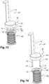
- FIGS 13 and 14 show a variant embodiment of the invention in which the filter basket 55' is fixed to the stopper 52 in a removable manner, thereby allowing the filter basket to be disassembled from the rest of the plug 10', and thus facilitating the cleaning thereof.
- the plug 10' according to the variant embodiment in figures 13 and 14 comprises all of the features of the plug 10 described above, apart from those that contradict the following.
- the slots 72 in the ring of the plug 10 are replaced in this case by cutouts 72' which open out at the external peripheral edge of the ring 62'.
- the notches 72' are designed to allow the rods 70 carried by the stopper 52 to slide and move.
- Each notch 72' has in this case an elongate shape and is oriented substantially circumferentially about the axis A.
- Each notch 72' opens out at the peripheral edge of the ring 62' so as to define a lateral opening.
- Each notch 72' has a width (or radial dimension with respect to the axis A) greater than the diameter of or than the transverse dimension of the rod 70 and a length (or dimension in the circumferential direction) much greater than the diameter of the rod 70, such that the rods can slide freely in the slots in order to allow the abovementioned movements of the stopper 52 and of the filter basket 55' with respect to one another.
- the opening of each notch 72' has a width (or circumferential dimension) which is greater than the diameter of the rod 70 in order to allow the rod 70 to come out of the notch and to allow the filter basket 55' to be disassembled from the stopper 52.
- the ends of the rods 70 bearing the widened parts 74 may be spaced apart from one another, preferably manually by a user, in order to be able to take them out of the notches 72'.
- the opposite ends of the rods 70 from these widened parts 74 are anchored in the seal 53 of the stopper 52.
- the rods 70 can be moved with respect to one another, for example by spacing apart their widened parts 74, by elastic deformation of the seal 53.
- the rods 70 are for example movable from a rest position in which they are approximately parallel to a disassembly position in which they form an angle in the region of 10-20°, for example, between one another.
- the lower disk of the stopper 52 should not impede the movement of the rods 70. It may comprise orifices through which the rods pass with play or else it may have an outside diameter less than the diameter of a circumference centered on the axis A and on which the rods 70 are located.
- the invention has the advantage of combining the function of sealing and the function of filtering in a single component. This main advantage is combined with the following advantages:
Landscapes
- Engineering & Computer Science (AREA)
- Environmental & Geological Engineering (AREA)
- Health & Medical Sciences (AREA)
- Life Sciences & Earth Sciences (AREA)
- Hydrology & Water Resources (AREA)
- Public Health (AREA)
- Water Supply & Treatment (AREA)
- Food Science & Technology (AREA)
- Food-Manufacturing Devices (AREA)
- Filtration Of Liquid (AREA)
- Frying-Pans Or Fryers (AREA)
Description
- The present invention relates to a filtering drain plug for a kitchen appliance and in particular of a cooking appliance such as a braising pan or fryer.
- Numerous professional cooking appliances have a cooking vessel, this vessel being able to have a drain hole or evacuation hole for cooking products and/or cooking water or washing water. It is known to equip the drain hole of this type of appliance with a drain plug.
-
GB289356 A -
US 2075443 A relates generally to drains for water receptacles and the like and more particularly to the construction of an improved drain in which is included a valve structure for preventing the escape of the water through the drain pipe. -
DE 29911165 U1 relates to an innovative drain dirt collecting element against pipe clogging. -
US 6276000 B1 relates to a combined strainer and stopper device for basins, sinks and the like. -
US20100071122A1 relates to a pop-up stopper having draining and straining functions. -
US 2792574 A relates to strainers particularly adapted for use in sinks, and has for a specific object the provision of expendable cups for collecting refuse. -
US 1173798 A related to providing a plug to stop the outlet in a kitchen sink, which may be readily applied to the ordinary drain pipe, having a strainer plate at the base of the sink over its inlet, and having its end outwardly flared and screwed into the base of the sink. - For example, a conventional braising pan comprises a cooking vessel, the drain hole of which is equipped with a drain plug which consists simply of a stopper made of synthetic material, generally polytetrafluoroethylene (PTFE), in order to be heat resistant and to have a degree of elasticity so as to seal off the vessel. This plug is generally quite tall and has in its top part gripping means which are intended to be located above the maximum upper level of liquid contained in the vessel in order to be accessible to a user.
- This plug may also be in the form of a tube and have a predetermined height in order to act as an overflow. The liquid in the vessel that is located above its maximum upper level then flows through the inside of the tube to the drain hole.
- Further, more advanced appliances comprise a drain plug of small diameter that is intended only for washing water and cooking water. This plug generally has a small throughput and does not have gripping means. It is generally controlled by means located under the vessel, it being possible for said means to be motorized. This is the case in particular for a conventional sink plug.
- This type of plug is generally associated with a tilting vessel, the tilting of the vessel serving in this case mainly to collect the cooking products contained in the vessel. Depending on the type of cooking that is carried out, users employ various accessories such as sieves of strainers in order to filter for example juices or sauces. They can also use a funnel when cooking pasta or vegetables in order to evacuate the cooking water before collecting the cooked products.
-
US-B 1-6,276,000 - The invention provides an improvement to the existing technologies which is simple, effective and economical.
- The invention thus proposes a filtering drain plug according to claim 1.
- The invention thus proposes a filtering drain plug, that is to say a drain plug equipped with filtering means which in this case comprise a filter basket. According to the invention, this filter basket is mounted so as to be able to move with respect to the stopper, this having numerous advantages since it makes it possible, in particular, to carry out, in a practical manner, various operations associated with the draining of a vessel of a professional cooking appliance. The invention makes it possible for example to filter the products in the vessel to be evacuated if the user so wishes. It is compatible with a large-diameter drain hole and does not require additional accessories such as a strainer for example.
- The filter basket is mounted so as to be able to move in translation along a longitudinal axis of the stopper and/or in rotation along this longitudinal axis and/or in rotation along an approximately transverse axis of the stopper.
- The plug is configured for example such that the filter basket is movable at least:
- from a first position in which it is close to the stopper to a second position in which it is spaced apart from the stopper, the movement of the filter basket from the first position to the second position being carried out by the filter basket being moved in translation along the longitudinal axis of the stopper, and/or
- from a third position in which it is approximately coaxial with the stopper to a fourth position in which its longitudinal axis forms an angle with that of the stopper, the movement of the filter basket from the third position to the fourth position being carried out by the filter basket being rotated about an approximately transverse axis.
- The movement of the filter basket from the first to the second position can be likened to a movement of the stopper along its longitudinal axis, between a position in which it is close to the filter basket and a position in which it is spaced apart therefrom. This makes it possible for example for a user to withdraw the stopper from the drain hole (in order to drain the vessel) while leaving the filter basket in place in the drain hole, in order that the cooking products are filtered.
- The movement of the filter basket from the third to the fourth position can be likened to a movement of the stopper about a transverse axis, between a position in which the stopper and the basket are coaxial and another position in which they are no longer coaxial. This makes it possible for example for a user, in particular when the stopper is spaced apart from the filter basket (and is for example in the abovementioned second position), to tilt the stopper in order to provide access to the interior of the filter basket. It is thus easier to collect the products contained in the basket or to wash the latter, for example.
- The filter basket preferably comprises at least one filter wall having a plurality of orifices for liquid to pass through. This filter wall has for example an elongate tubular shape. It may have a cylindrical shape. The orifices for liquid to pass through may have an orientation that is substantially radial with respect to a longitudinal axis of the filter wall.
- The filter basket may be fixed to the stopper in a removable manner. The filter basket is thus of the removable type, thereby making it easier to clean.
- Advantageously, the filter basket defines an internal space, one longitudinal end of which is closed by a transverse wall integral with the filter basket. This transverse wall preferably has a disk shape.
- The filter basket is connected, at its end opposite said transverse wall, to a ring. The ring has an outside diameter greater than an outside diameter or than the maximum transverse dimension of said filter basket. The external periphery of the ring can thus form bearing means, in particular axial bearing means.
- The ring comprises at least one orifice or cutout in which a rod carried by the stopper is mounted so as to be able to slide and/or rotate. Preferably, the ring comprises two diametrically opposite orifices or cutouts in each of which a rod carried by the stopper is mounted so as to be able to slide and/or rotate.
- The orifices or cutouts may be designed to allow the filter basket to be disassembled from the stopper, for example by removing the rod from each of these orifices or cutouts. For this purpose, the rods may be movable with respect to one another, for example by being spaced apart from one another. One end of each rod may be anchored in an elastically deformable block of the stopper, thereby allowing the opposite free end of the rod to move.
- The stopper is preferably connected to a handle for handling the plug. The plug according to the invention is thus able to be handled manually, for example in order to manually regulate the rate of draining of a vessel. Specifically, all that is necessary is to remove the stopper from the drain hole and to space it apart to a greater or lesser extent from this hole in order to regulate the rate of draining, which depends in particular on the flow cross section delimited between the stopper and the drain hole.
- The handle may be connected to one end of a bar the opposite end of which is connected to the stopper. This bar is preferably graduated. It may be approximately parallel to the longitudinal axis of the stopper.
- The stopper is preferably designed to be inserted entirely into the drain hole. The stopper thus does not project from the wall having this drain hole. This is particularly advantageous in particular in the context of a cooking wall, since the stopper does not take up room in the cooking space defined by the wall. The bottom of the vessel having this cooking wall is thus free, thereby providing the user with greater comfort and useful cooking area.
- The handle may also be designed to limit its size. It preferably has a shape that makes it possible to avoid accidental opening of the plug while foodstuffs are being put in the vessel or cooked.
- The present invention also relates to a drain plug, which is preferably removable, for a drain hole, in particular of a kitchen appliance, having a stopper designed to shut off said drain hole, and a filter basket which is designed to be received in said drain hole, beneath said stopper, characterized in that the filter basket is mounted so as to be able to slide and/or rotate on at least one rod carried by the stopper. This stopper may comprise all or some of the abovementioned features.
- The present invention also relates to an assembly having a drain plug as described above and a vessel, in particular a cooking vessel, this vessel having a wall equipped with a drain hole in which said plug is mounted, preferably in a removable manner.
- Advantageously, the drain hole comprises an internal cylindrical shoulder the inside diameter of which is greater than the outside diameter or than the maximum transverse dimension of said transverse wall and less than the outside diameter of said ring. It will thus be understood that the ring of the filter basket is able to bear axially on the shoulder of the drain hole. This makes it possible to precisely and stably position the filter basket in the drain hole.
- Preferably, the handle comprises or forms bearing means for bearing on a part of the vessel and means for keeping the stopper in a position for draining the vessel. The user can thus lift the stopper in order to remove it from the drain hole and rest the handle or the bearing means thereof on the part of the vessel in order that the stopper is kept in this raised position. The filter basket, which remains in the drain hole, thus receives the products contained in the vessel, which are thus filtered.
- The present invention further relates to an assembly having a vessel, in particular a cooking vessel, and a drain plug, which is preferably removable, for a drain hole of said vessel, the drain plug having a stopper designed to shut off said drain hole, and a filter basket which is designed to be received in said drain hole, beneath said stopper, and which is mounted so as to be able to move with respect to the stopper, characterized in that the stopper is connected to a handle for handling the plug, this handle comprising or forming bearing means for bearing on a part of the vessel and means for keeping the stopper in a position for draining the vessel. This assembly may comprise all or some of the abovementioned features relating to the plug.
- Finally, the invention relates to a kitchen appliance, in particular a cooking appliance, having a drain plug or an assembly as described above.
- The invention will be better understood and further details, features and advantages of the invention will become apparent from reading the following description that is given by way of nonlimiting example with reference to the appended drawings, in which:
-
figures 1 and 2 are schematic perspective views of a cooking appliance according to the invention, this appliance having in this case at least one removable collecting tank which is in the stowed position infigure 1 and the extracted position infigure 2 , -
figure 3 is a schematic perspective view of a cooking vessel of the appliance fromfigures 1 and 2 , this vessel having a cooking wall having a drain hole in which a filtering drain plug according to the invention is mounted, -
figure 4 is a schematic perspective and sectional view of the cooking appliance, of the vessel and of the filtering plug fromfigures 1 to 3 , the stopper of the filtering plug being in this case in the raised position or position for draining the vessel, -
figure 5 is another schematic perspective and sectional view of the vessel and of the filtering plug fromfigures 1 to 3 , the stopper of the filtering plug being in this case in the lowered position or position for shutting off the drain hole of the vessel, -
figures 6 and 7 are partial schematic perspective views of the handle of the filtering plug and of the cooking vessel, -
figures 8 to 10 are schematic perspective views of the filtering plug fromfigures 3 to 5 , -
figure 11 is a schematic perspective view in axial section of the filtering plug fromfigures 3 to 5 , -
figure 12 is another schematic perspective view of the filtering plug fromfigures 3 to 5 , and -
figures 13 and 14 are schematic perspective views of a variant embodiment of the filtering drain plug according to the invention. - The figures show particular exemplary embodiments of a
filtering drain plug 10 according to the invention (visible in particular infigures 6 to 9 ) and also of akitchen appliance 20, in particular a cooking appliance, equipped with thisplug 10. -
Figures 1 and 2 show thecooking appliance 20 as a whole, the cooking appliance in this case being a braising pan or fryer. - Typically, this type of appliance has a parallelepipedal overall shape and has an approximately vertical front face (that is accessible to a user) and an approximately vertical rear face, approximately vertical side faces that are perpendicular to the front and rear faces, and an approximately horizontal upper face (that is also accessible to a user) and an approximately horizontal lower face. As in the example shown, in order to set the upper face of the
appliance 20 at a given height and to make it easier to clean the ground under the appliance, theappliance 20 may be equipped with height-adjustable feet 22, resting on the ground, which are connected to the lower face of the appliance. - The
appliance 20 has essentially two parts, anupper part 24 and alower part 26. Thelower part 26 of the appliance comprises two side walls which define between one another aspace 28 for housing at least onecollecting tank space 28 opens onto the front face of theappliance 20 such that thetanks - The
tanks frame 34, for example by way of a system of slide rails. Thetanks - The
tanks figure 1 , in which they are both housed in thespace 28, to an extracted position, shown infigure 2 , in which they are both extracted from thespace 28. They can be moved into any intermediate position between the two abovementioned extreme positions. - The
tank 30, located at the front, can be a tank for collecting cooking products (such as a GN tank). Thetank 32, located at the rear, can be a tank for collecting cooking oil, in this case having a smaller volume than thetank 30. - The
upper part 34 of theappliance 20 comprises means for heating and for regulating the heating of acooking wall 36, which is in this case an approximately horizontal lower wall of acooking vessel 38. - The
cooking vessel 38 has in this case an approximately vertical front wall and rear wall and approximately vertical side walls. These walls extend upward from thecooking wall 36 and define with the latter a volume intended to contain products to be cooked. The front wall forms in this case a dihedron, the apex of which is oriented toward the front of theappliance 20. - The
vessel 38 is in this case of the fixed type, that is to say it is mounted in a fixed manner on theappliance 20 and is not intended to be removed or tilted in order to be drained. - The
cooking wall 36 preferably comprises asingle drain hole 40. This limits cleaning and simplifies thecooking vessel 38 compared with a separate drain for the product and a drain for washing or cooking water. Thehole 40 is in this case located in the vicinity of the front end of thecooking wall 36, approximately in the middle of the latter. It can be seen infigures 3 and 4 that the vertical median plane of theappliance 20 passing from the front to the rear in the middle of thevessel 38 passes through thehole 40 and through the apex of the abovementioned dihedron. - The means for heating and regulating the heating of the
appliance 20 are not part of the invention and will not be described in the present application. The regulating means are located on the front face of theappliance 20 and are accessible to the user. The heating means are located beneath thecooktop 36. - The
upper part 24 of theappliance 20 can be connected by an appropriate means 42 to a general water inlet, with a view to using water for cooking the products and for cleaning thevessel 38 after it has been used. - The
upper part 34 of theappliance 20 furthermore comprises an approximately horizontallower wall 44 which extends under thecooking wall 36 and at a distance therefrom. - The
wall 44 comprises ahole 46 for draining thevessel 38, which is aligned vertically with thehole 40 in thevessel 38. Theholes cylindrical tube 48 which may have a diameter greater than or equal to 30 or 40 mm, for example 60 mm. - The upper end of the
tube 48 is fixed beneath thecooktop 36 and its lower end can pass through thehole 46 and project from the inner face of the wall 44 (figure 4 ). Anannular seal 49 may be mounted between the lower end of thetube 48 and the peripheral edge of thehole 46. - The
tube 48 comprises an internalcylindrical shoulder 50 in the vicinity of its upper end. - According to the invention, the
cooking appliance 20 is equipped with afiltering drain plug 10 which makes it possible in a reliable and economical manner to drain thevessel 38 and to separate the solid cooking products from the liquid cooking products, such as pasta from its cooking water. -
Figures 3 to 12 show one embodiment of afiltering drain plug 10 according to the invention. - In the example shown, the
filtering plug 10 comprises essentially three parts: astopper 52, afilter basket 55 and ahandling handle 56. - The
stopper 52 has a cylindrical or frustoconical overall shape and is shaped so as to shut off thehole 40 in thecooking wall 36 in a sealed manner. - In the example shown, it comprises two substantially coaxial disks, an
upper disk 52a and alower disk 52b, between which anannular seal 53 is mounted. Thedisks pin 54 and a screw for example, the pin being in this case aligned with the longitudinal axis A of thestopper 52. The space between the disks is occupied by theseal 53, which is formed in this case by an annular block which is produced preferably from a material that is resistant to temperature, oils and detergents, such as a high-temperature silicone. Theseal 53 has an outside diameter greater than that of thelower disk 52b such that it can engage with the internal peripheral edge of thehole 40 and the internal cylindrical surface of thetube 48. In the example shown, theseal 53 has a frustoconical overall shape, its lower end having a diameter less than that of its upper end. The frustoconical shape has the advantage of allowing slight compression of the seal when a vertical pressure is applied to the plug and, conversely, a slight traction on the plug rapidly frees the seal. Theupper disk 52a preferably has an outside diameter less than that of the upper end of theseal 53 and also less than the inside diameter of thehole 40. Theseal 53 is sandwiched between the twodisks pin 54. - The
stopper 52 is preferably designed to be housed in the upper end of thetube 48 such that the upper face of itsupper disk 52a is aligned with the upper face of thecooking wall 36, as is visible infigure 5 . Thestopper 52 has a height or thickness which is equal to the longitudinal distance between the lower face of thedisk 52b and the upper face of thedisk 52a. - The
stopper 52 of the plug could of course have some other design. It could for example comprise a cylindrical or frustoconical body that is surrounded by one or more O-ring seals that are intended to engage with the internal peripheral edge of the drain hole and/or the internal cylindrical surface of the drain tube. - The
stopper 52 is connected to thehandle 56 by abar 58 which extends parallel to the axis A of the stopper and which has a length slightly less than the depth of thevessel 38. As is visible infigure 5 , when thestopper 52 is mounted in thehole 40 and shuts it off, thebar 58 extends upward and thehandle 56 is located just below theupper edge 59 of thevessel 38. When thestopper 52 is lifted and removed from thehole 40 by means of thehandle 56, the latter can be positioned on theupper edge 59 of the vessel in order to keep the stopper in a raised position for draining thevessel 38, as is visible infigures 3 and 4 . - The
handle 56 is in this case formed by bending the upper end of thebar 58 so as to form a lip which is approximately perpendicular to the axis A and approximately horizontal in use. Thehandle 56 has a small thickness (identical to that of the bar 58). - In the example shown, the
handle 56 has a shape more or less complementary to that of the front dihedral wall of thevessel 38. Thehandle 56 has in this case an end in the shape of an arrow and a pointed profile, the apex of which is intended to be oriented toward the front face of theappliance 20. - In order to position the handle on the
upper edge 59 of thevessel 38, it is necessary first of all to pull thestopper 52 upward by means of thehandle 56, in a direction parallel to the axis A, until thestopper 52 comes out of thehole 40 and thehandle 56 is located substantially above a horizontal plane passing through theupper edge 59 of the vessel. This movement is rendered possible by the shape complementarity of thehandle 56 with respect to the front wall of the vessel, the handle being able to slide or rub over this wall during the movement. Slight tilting of thehandle 56 and thus of thestopper 58 toward the front of theappliance 20 may be necessary in order to move thehandle 56 above theedge 59 of the vessel. This tilting is rendered possible by the capacity of thestopper 52 to rotate with respect to thefilter basket 58, and of the filter basket to rotate with respect to the stopper, about at least one transverse axis, as will be described in more detail in the following text. It may also be necessary for theplug 10 to be rotated about the axis A by thehandle 56. Thehandle 56 may then be positioned on theedge 59 of the vessel in order to keep the stopper in the raised position (figures 4 and 5 ). - Advantageously, as shown in
figures 6 and 7 , theedge 59 of thevessel 38 has arecess 59a for housing thehandle 56. Therecess 59a and thehandle 56 have complementary shapes that allow the handle to be positioned precisely and securely. In the example shown, therecess 59a has a depth approximately equal to the thickness of thehandle 56 such that the upper face of the handle is aligned with the upper surface of thevessel 38 and of the cooking appliance. The recess has an end in the shape of an arrow and a pointed profile and comprises, at its opposite ends,protrusions 59b for retaining thehandle 56. Thus, when theplug 10 is in the position shown infigure 7 , even if the user accidentally touches the filtering plug, the latter remains in place. - As shown in the drawings, the
bar 58 may be graduated in order to indicate the volume of products contained in thevessel 38 to the user. It may for example comprise notches or lines that are regularly distributed along at least a part of its length. Of course, the volume of thevessel 38 depends on the dimensions thereof. - The
filter basket 55 is mounted coaxially with thestopper 52. It comprises a cylindricaltubular wall 60 having orifices or slots for fluids to pass through, these orifices being oriented substantially radially with respect to the axis A. These orifices or slots are calibrated so as to retain the majority of common foodstuffs. Their shapes and dimensions can be different depending on the applications envisioned. Thewall 60 extends between anupper ring 62 and alower disk 64 which are disposed coaxially with the wall. - The
lower disk 64 closes the lower end of the internal volume defined by thewall 60. Thedisk 64 may comprise at least one orifice orslot 65, as is visible infigure 10 . Thedisk 64 has an outside diameter greater than that of thewall 60 and less than the inside diameter of thetube 48. Thedisk 64 defines with the tube 48 a predetermined rate of drainage. Specifically, the radial play between the external periphery of thedisk 64 and the internal cylindrical surface of the tube 48 (that is to say the difference between the inside diameter of thetube 48 and the outside diameter of the disk 64) defines a predetermined annular flow cross section for liquid. - The
upper ring 62 comprises an internal peripheral edge the diameter of which is close to the inside diameter of thewall 60, and an outside diameter which is greater than that of thewall 60 and also than that of thedisk 64. The outside diameter of thering 62 is greater than the inside diameter of the shoulder of the tube 48 (and less than the outside diameter of this shoulder) such that thering 62 can bear axially on this shoulder, as is visible infigures 4 and 5 . As a result of this bearing, the products to be drained cannot pass between thering 62 and thetube 48 but are obliged to pass through thering 62 and to be filtered by thetubular wall 60. - According to the invention, the
filter basket 55 is mounted so as to be able to move, in this case in translation and in rotation, with respect to thestopper 52. In the example shown, thefilter basket 55 and thestopper 52 are able to move in translation with respect to one another in a direction parallel to the axis A. They are thus movable from a moved-together position (figure 5 ) in which thelower disk 52b of the stopper is close to thering 62, or even bearing axially on the latter, and a spaced-apart position (figures 3, 4 and8 to11 ) in which thestopper 52 and thefilter basket 55 are at an axial distance from one another. This axial movement can be realized by simply pulling the handle along the axis A. Thefilter basket 55 and thestopper 52 are also able to move in rotation with respect to one another about the axis A, in this case with a small angular travel. Thefilter basket 55 and thestopper 52 are also able to move in rotation with respect to one another about a transverse axis B, in this case with a larger angular travel. They are thus movable from the spaced-apart position infigures 3, 4 and8 to11 to a tilted position (figure 9 ) in which the longitudinal axes of thestopper 52 and of thefilter basket 55 form a non-zero angle between one another. This axial movement can be realized by simply handling the stopper by means of thehandle 56. - In the example shown, these movements are rendered possible by
rods 70 that are integral with thestopper 52 and mounted so as to slide in orifices orslots 72 in thefilter basket 55. - The
rods 70, of which there are two in this case, extend parallel to the axis A and their upper ends are fixed to thelower disk 52b of thestopper 52. They thus extend downwardly from thestopper 52. Therods 70 are in this case diametrically opposite one another. Therods 70 have an elongate cylindrical shape in this case. They each carry at their lower end awidened part 74 that forms a stop. This widened part could be formed by a nut screwed onto a threaded part of each rod. - The
slots 72 for therods 70 to slide in are formed in this case in thering 62 of thefilter basket 55. There are twosuch slots 72 and they are diametrically opposite one another. Eachslot 72 has an elongate shape and may be oriented substantially circumferentially about the axis A. Eachslot 72 has in this case an approximately ellipsoidal or oval shape. Eachslot 72 has a width (or radial dimension with respect to the axis A) greater than the diameter or than the transverse dimension of therod 70 and a length (or dimension in the circumferential direction) much greater than the diameter of therod 70, such that the rods can slide freely in the slots in order to allow the abovementioned movements of thestopper 52 and of thefilter basket 55 with respect to one another. - The axial range of movement of the
stopper 52 with respect to thefilter basket 55 is defined in this case by thering 62 bearing on thestopper 52 on the one hand and on the widenedlower parts 74 of therods 70 on the other hand. The angular travel of thestopper 52 with respect to thefilter basket 55 about the axis A is defined in this case by therods 70 bearing on circumferential ends of the peripheral edges of theslots 72 on the one hand and on the opposite circumferential ends of these peripheral edges on the other hand. This angular travel is for example around 5-10°. The angular travel of thestopper 52 with respect to thefilter basket 55 about the axis B is defined in this case by therods 70 bearing on circumferential ends of the peripheral edges of the slots 72 (at the upper face of the ring 62) and simultaneously by the widened lower parts thereof bearing on the opposite circumferential ends of these peripheral edges (at the lower face of the ring 62), as is visible infigure 9 . The angular travel between the tilted position infigure 9 and a position in which thestopper 52 and thefilter basket 55 are coaxial is in the region of 40-60°. This angle makes it possible to completely free the upper opening in thefilter basket 55, as is visible infigure 12 . - The various components of the
filter basket 55 can be produced from metal material(s) and be joined together by welding or brazing. These components and also the other metal parts (such as thedisks pin 54 and the bar 58) of the plug can be made of stainless steel, thereby making them dishwasher-proof. - The
filtering drain plug 10 can for example be used in the following way. - The
cooking vessel 38 is empty and theplug 10 is fitted in thedrain hole 40 by means of itshandle 56. For this purpose, thefilter basket 55 is inserted into thetube 48 through thehole 40 such that it bears by way of itsring 62 on theshoulder 50 of thetube 48. A slight pressure is applied to the stopper 52 (in the vertical direction from top to bottom) by means of thehandle 56 such that it passes into thehole 40 and shuts it off in a sealed manner. Theplug 10 is then in the position shown infigure 5 . Thekitchen appliance 20 can be used for example for cooking pasta, it being possible for the water to be introduced into the vessel by themeans 42. After the pasta has been cooked in the vessel, it is necessary to drain it off. For this purpose, thestopper 52 is removed from the hole and thehandle 56 is positioned on theupper edge 59 of the vessel 38 (figures 3 and 4 ). The user may prefer to hold the plug himself in order to regulate the rate of draining of the vessel himself. The cooking water then flows through the space between thestopper 52 and the peripheral edge of theorifice 40 as far as thefilter basket 55, in which it is filtered. Any pasta which passes through this space is retained by thefilter basket 55. The cooking water which enters the filter basket passes through the orifices in thewall 60 thereof and then flows between thedisk 64 and thetube 48 as far as the sewer through appropriate evacuation means. If thefilter basket 55 is full and can no longer carry out its function, the user can raise the plug further in order to detach thebasket 55 slightly from theshoulder 50 so as to facilitate the flow, without having to put his hands in the vessel. Theslot 65 in thelower disk 64 of thefilter basket 55 allows the filter basket to be emptied completely. Once the cooking water from the vessel has been removed entirely, theplug 10 can be removed fully from thedrain hole 40 and the pasta can be evacuated through thehole 40 and collected in thetank 30 located under the cooking vessel. All that is then necessary is to remove thetank 30 from thespace 28 in order to serve the pasta. It is also possible to collect the pasta located in thebasket 55. The tilting of thestopper 52 with respect to thebasket 55 makes it possible to easily empty the latter even though it is linked to the stopper. The tilting makes it possible to free the upper end of thebasket 55 entirely. Similarly, cleaning of thebasket 55 can be carried out under a faucet for example by passing it upside down under the latter, this operation not being hindered by thering 62, the inside diameter of which is approximately equal to that of thefiltering wall 60. - Reference is now made to
figures 13 and 14 , which show a variant embodiment of the invention in which the filter basket 55' is fixed to thestopper 52 in a removable manner, thereby allowing the filter basket to be disassembled from the rest of the plug 10', and thus facilitating the cleaning thereof. - The plug 10' according to the variant embodiment in
figures 13 and 14 comprises all of the features of theplug 10 described above, apart from those that contradict the following. - In the example shown, the
slots 72 in the ring of theplug 10 are replaced in this case by cutouts 72' which open out at the external peripheral edge of the ring 62'. As is the case for theslots 72, the notches 72' are designed to allow therods 70 carried by thestopper 52 to slide and move. There are two notches 72' and they are diametrically opposite one another. Each notch 72' has in this case an elongate shape and is oriented substantially circumferentially about the axis A. Each notch 72' opens out at the peripheral edge of the ring 62' so as to define a lateral opening. Each notch 72' has a width (or radial dimension with respect to the axis A) greater than the diameter of or than the transverse dimension of therod 70 and a length (or dimension in the circumferential direction) much greater than the diameter of therod 70, such that the rods can slide freely in the slots in order to allow the abovementioned movements of thestopper 52 and of the filter basket 55' with respect to one another. Moreover, the opening of each notch 72' has a width (or circumferential dimension) which is greater than the diameter of therod 70 in order to allow therod 70 to come out of the notch and to allow the filter basket 55' to be disassembled from thestopper 52. - The ends of the
rods 70 bearing the widenedparts 74 may be spaced apart from one another, preferably manually by a user, in order to be able to take them out of the notches 72'. - In the example shown, the opposite ends of the
rods 70 from these widenedparts 74 are anchored in theseal 53 of thestopper 52. Therods 70 can be moved with respect to one another, for example by spacing apart their widenedparts 74, by elastic deformation of theseal 53. Therods 70 are for example movable from a rest position in which they are approximately parallel to a disassembly position in which they form an angle in the region of 10-20°, for example, between one another. - The lower disk of the
stopper 52, which is not visible here, should not impede the movement of therods 70. It may comprise orifices through which the rods pass with play or else it may have an outside diameter less than the diameter of a circumference centered on the axis A and on which therods 70 are located. - Generally, the invention has the advantage of combining the function of sealing and the function of filtering in a single component. This main advantage is combined with the following advantages:
- possibility of manually managing the flow rate by lifting the plug to a greater or lesser extent,
- possibility of a non-filtered maximum flow rate for large pieces for example,
- filtering position by positioning the handle in a dedicated shape of the appliance,
- possibility of calibrating the flow rate through the basket by dimensioning its lower disk,
- little influence of the plug on the cooking area (only the section of the handle is not usable),
- possibility of managing drainage and filtering from the handle located at the top of the vessel,
- ease of cleaning the basket by virtue of the movement thereof with respect to the stopper and on account of the fact that the upper end of the basket is open and free of any mechanism,
- captive basket (since it is not removable from the plug), and
- possibility of positioning a filtering sock in the filter basket for fine filtering.
- The word approximately is used in connection with various terms herein, including the terms transverse, coaxial and parallel. Alternatively, the word substantially may be used in connection with any of the various terms, and in accordance with its plain
and ordinary meaning to those of ordinary skill in the art.
Claims (12)
- A drain plug (10, 10'), which is preferably removable, for a drain hole (40), in particular of a kitchen appliance (20), having a stopper (52) designed to shut off said drain hole, and a filter basket (55, 55') which is designed to be received in said drain hole below said stopper, said filter basket being mounted so as to be able to move by sliding and/or by rotating with respect to a rod (70) carried by the stopper;
characterized in that the filter basket (55, 55') is connected, at its end opposite a transverse wall, to a ring (62, 62') wherein the ring (62, 62') comprises at least one orifice (72, 72') in which said rod (70) carried by, and extending downwardly from, the stopper (52) is mounted so as to be able to slide and/or rotate, wherein the filter basket (55, 55') is mounted so as to be able to move in translation along a longitudinal axis (A) of the stopper (52) and/or in rotation along this longitudinal axis and/or in rotation along an approximately transverse axis (B) of the stopper. - The drain plug (10, 10') as claimed in claim 1, characterized in that it is designed such that the filter basket (55, 55') is movable at least:- from a first position in which it is close to the stopper (52) to a second position in which it is spaced apart from the stopper, the movement of the filter basket from the first position to the second position being carried out by the filter basket being moved in translation along the longitudinal axis (A) of the stopper, and/or- from a third position in which it is approximately coaxial with the stopper to a fourth position in which its longitudinal axis forms an angle with that of the stopper, the movement of the filter basket from the third position to the fourth position being carried out by the filter basket being rotated about an approximately transverse axis (B).
- The drain plug (10, 10') as claimed in one of the preceding claims, characterized in that the filter basket (55, 55') comprises at least one filter wall (60) having a plurality of orifices for liquid to pass through, this filter wall having for example an elongate tubular shape.
- The drain plug (10') as claimed in one of the preceding claims, characterized in that the filter basket (55') is fixed to the stopper (52) in a removable manner.
- The drain plug (10, 10') as claimed in one of the preceding claims, characterized in that the filter basket (55, 55') defines an internal space, one longitudinal end of which is closed by a transverse wall integral with the filter basket, said transverse wall preferably having a disk shape (64).
- The drain plug (10, 10') as claimed in claim 1, characterized in that said ring (62, 62') has an outside diameter greater than an outside diameter or than the maximum transverse dimension of said filter basket (55, 55').
- The drain plug (10, 10') as claimed in one of the preceding claims, characterized in that the stopper (52) is connected to a handle (56) for handling the plug.
- The drain plug (10, 10') as claimed in claim 7, characterized in that the handle (56) is connected to one end of a bar (58) the opposite end of which is connected to the stopper (52), this bar preferably being graduated and/or approximately parallel to the longitudinal axis of the stopper.
- An assembly having a plug (10, 10') as claimed in one of the preceding claims and a vessel (38), in particular a cooking vessel, this vessel having a wall (36) equipped with a drain hole (40) in which said drain plug (10, 10') is mounted, preferably in a removable manner, the stopper (52) of the plug being preferably designed to be inserted entirely into the drain hole.
- The assembly as claimed in claim 9, the plug (10, 10') having the features of claim 1, characterized in that said drain hole (40) comprises an internal cylindrical shoulder (50) the inside diameter of which is greater than the outside diameter or than the maximum transverse dimension of said transverse wall and less than the outside diameter of said ring (62, 62').
- The assembly as claimed in claim 9 or 10, the plug (10, 10') having the features of claim 7 or 8, characterized in that the handle (56) comprises or forms bearing means for bearing on a part (59) of the vessel (38) and means for keeping the stopper (52) in a position for draining the vessel.
- A kitchen appliance, in particular a cooking appliance, having a drain plug (10, 10') as claimed in one of claims 1 to 8 or an assembly as claimed in one of claims 9 to 11.
Applications Claiming Priority (2)
| Application Number | Priority Date | Filing Date | Title |
|---|---|---|---|
| FR1453236A FR3019723B1 (en) | 2014-04-11 | 2014-04-11 | FILTERING DRAIN BUTTON FOR A KITCHEN APPLIANCE |
| PCT/US2015/024896 WO2015157400A1 (en) | 2014-04-11 | 2015-04-08 | Filtering drain plug for a kitchen appliance |
Publications (2)
| Publication Number | Publication Date |
|---|---|
| EP3128885A1 EP3128885A1 (en) | 2017-02-15 |
| EP3128885B1 true EP3128885B1 (en) | 2023-06-07 |
Family
ID=51225699
Family Applications (1)
| Application Number | Title | Priority Date | Filing Date |
|---|---|---|---|
| EP15719044.8A Active EP3128885B1 (en) | 2014-04-11 | 2015-04-08 | Filtering drain plug for a kitchen appliance |
Country Status (4)
| Country | Link |
|---|---|
| US (1) | US20170119210A1 (en) |
| EP (1) | EP3128885B1 (en) |
| FR (1) | FR3019723B1 (en) |
| WO (1) | WO2015157400A1 (en) |
Families Citing this family (2)
| Publication number | Priority date | Publication date | Assignee | Title |
|---|---|---|---|---|
| US10743714B2 (en) | 2017-02-03 | 2020-08-18 | Illinois Tool Works Inc. | Kitchen cooking appliance with mobile drain fluid receptacle |
| CN107401199A (en) * | 2017-08-20 | 2017-11-28 | 曹学虎 | A kind of anti-blocking outlet device of easy to clean |
Citations (7)
| Publication number | Priority date | Publication date | Assignee | Title |
|---|---|---|---|---|
| US1173798A (en) * | 1915-11-12 | 1916-02-29 | Wilburn Fairchild | Kitchen-sink plug. |
| GB289356A (en) * | 1927-11-17 | 1928-04-26 | William Halket | Improvements in sinks |
| US2075443A (en) * | 1934-01-20 | 1937-03-30 | Kirschner Louis | Combined strainer and valve |
| US2792574A (en) * | 1956-01-04 | 1957-05-21 | Donald C Austin | Strainer |
| DE29911165U1 (en) * | 1999-06-23 | 1999-11-11 | Agricola, Christian, 66787 Wadgassen | Drain strainer |
| US6276000B1 (en) * | 2000-07-21 | 2001-08-21 | Husam Saman | Combined strainer and stopper for basin drain |
| US20100071122A1 (en) * | 2008-09-23 | 2010-03-25 | Yi-Chun Li | Pop-Up Stopper Having Draining and Straining Functions |
Family Cites Families (3)
| Publication number | Priority date | Publication date | Assignee | Title |
|---|---|---|---|---|
| US1511017A (en) * | 1923-09-17 | 1924-10-07 | Jacob G Binder | Sink-drain water stop |
| US5820183A (en) * | 1997-03-12 | 1998-10-13 | Marcus; Kenneth D. | Graduated tool handle |
| SE533660C2 (en) * | 2009-03-27 | 2010-11-23 | Seco Tools Ab | Cutting tip comprising a grooved shank and cutting tool including such cutting tip |
-
2014
- 2014-04-11 FR FR1453236A patent/FR3019723B1/en active Active
-
2015
- 2015-04-08 US US15/301,507 patent/US20170119210A1/en not_active Abandoned
- 2015-04-08 WO PCT/US2015/024896 patent/WO2015157400A1/en not_active Ceased
- 2015-04-08 EP EP15719044.8A patent/EP3128885B1/en active Active
Patent Citations (7)
| Publication number | Priority date | Publication date | Assignee | Title |
|---|---|---|---|---|
| US1173798A (en) * | 1915-11-12 | 1916-02-29 | Wilburn Fairchild | Kitchen-sink plug. |
| GB289356A (en) * | 1927-11-17 | 1928-04-26 | William Halket | Improvements in sinks |
| US2075443A (en) * | 1934-01-20 | 1937-03-30 | Kirschner Louis | Combined strainer and valve |
| US2792574A (en) * | 1956-01-04 | 1957-05-21 | Donald C Austin | Strainer |
| DE29911165U1 (en) * | 1999-06-23 | 1999-11-11 | Agricola, Christian, 66787 Wadgassen | Drain strainer |
| US6276000B1 (en) * | 2000-07-21 | 2001-08-21 | Husam Saman | Combined strainer and stopper for basin drain |
| US20100071122A1 (en) * | 2008-09-23 | 2010-03-25 | Yi-Chun Li | Pop-Up Stopper Having Draining and Straining Functions |
Also Published As
| Publication number | Publication date |
|---|---|
| EP3128885A1 (en) | 2017-02-15 |
| FR3019723A1 (en) | 2015-10-16 |
| WO2015157400A1 (en) | 2015-10-15 |
| US20170119210A1 (en) | 2017-05-04 |
| FR3019723B1 (en) | 2017-02-10 |
Similar Documents
| Publication | Publication Date | Title |
|---|---|---|
| US6532865B1 (en) | Food cooking vessel | |
| US7467718B1 (en) | Combination strainer and service bowl | |
| US4934420A (en) | Gravy separating device | |
| US5219006A (en) | Method and apparatus for a strainer funnel with support means | |
| US3648595A (en) | Food fryer with continuously filtered cooking oil | |
| EP3030116B1 (en) | Device for cooking and heating and/or reviving of portions of fresh and/or frozen pre-cooked pasta and other food preparations | |
| US7731846B1 (en) | Grease collection system | |
| US20160066743A1 (en) | Cooking Pot with Straining Lid and Spoon Support | |
| EP3324804A1 (en) | Food processing system presenting a guiding flow arrangement and process for use thereof | |
| EP2702911A1 (en) | Funnel-shaped roasting pan | |
| US20170119210A1 (en) | Filtering drain plug for a kitchen appliance | |
| EP3128884B1 (en) | Drainage device for a cooking appliance | |
| RU2649228C2 (en) | Universal colander for prevention of boiling liquid leakage and removing foam and slag | |
| CN102704552B (en) | Water tank | |
| US20130139705A1 (en) | Pot boss | |
| WO2019103949A1 (en) | Cooking appliance with integral drain | |
| RU2673348C2 (en) | Outlet valve for institutional kitchen kettle | |
| CN107635442B (en) | equipment for cooking food | |
| RU223363U1 (en) | KETTLE LID | |
| CN113397369B (en) | Pan with filtration | |
| US2186998A (en) | Kitchen sink | |
| WO2016175892A1 (en) | Multipurpose transparent hopper cup | |
| RU2649229C2 (en) | Device for a kitchen sink | |
| GB2422292A (en) | Deep fat fryer with means for emptying oil | |
| EP1782720A1 (en) | Drain cover |
Legal Events
| Date | Code | Title | Description |
|---|---|---|---|
| STAA | Information on the status of an ep patent application or granted ep patent |
Free format text: STATUS: THE INTERNATIONAL PUBLICATION HAS BEEN MADE |
|
| PUAI | Public reference made under article 153(3) epc to a published international application that has entered the european phase |
Free format text: ORIGINAL CODE: 0009012 |
|
| STAA | Information on the status of an ep patent application or granted ep patent |
Free format text: STATUS: REQUEST FOR EXAMINATION WAS MADE |
|
| 17P | Request for examination filed |
Effective date: 20160906 |
|
| AK | Designated contracting states |
Kind code of ref document: A1 Designated state(s): AL AT BE BG CH CY CZ DE DK EE ES FI FR GB GR HR HU IE IS IT LI LT LU LV MC MK MT NL NO PL PT RO RS SE SI SK SM TR |
|
| AX | Request for extension of the european patent |
Extension state: BA ME |
|
| DAV | Request for validation of the european patent (deleted) | ||
| DAX | Request for extension of the european patent (deleted) | ||
| STAA | Information on the status of an ep patent application or granted ep patent |
Free format text: STATUS: EXAMINATION IS IN PROGRESS |
|
| 17Q | First examination report despatched |
Effective date: 20190218 |
|
| GRAP | Despatch of communication of intention to grant a patent |
Free format text: ORIGINAL CODE: EPIDOSNIGR1 |
|
| STAA | Information on the status of an ep patent application or granted ep patent |
Free format text: STATUS: GRANT OF PATENT IS INTENDED |
|
| INTG | Intention to grant announced |
Effective date: 20221202 |
|
| GRAS | Grant fee paid |
Free format text: ORIGINAL CODE: EPIDOSNIGR3 |
|
| GRAA | (expected) grant |
Free format text: ORIGINAL CODE: 0009210 |
|
| STAA | Information on the status of an ep patent application or granted ep patent |
Free format text: STATUS: THE PATENT HAS BEEN GRANTED |
|
| AK | Designated contracting states |
Kind code of ref document: B1 Designated state(s): AL AT BE BG CH CY CZ DE DK EE ES FI FR GB GR HR HU IE IS IT LI LT LU LV MC MK MT NL NO PL PT RO RS SE SI SK SM TR |
|
| REG | Reference to a national code |
Ref country code: GB Ref legal event code: FG4D |
|
| REG | Reference to a national code |
Ref country code: CH Ref legal event code: EP Ref country code: AT Ref legal event code: REF Ref document number: 1572212 Country of ref document: AT Kind code of ref document: T Effective date: 20230615 |
|
| REG | Reference to a national code |
Ref country code: DE Ref legal event code: R096 Ref document number: 602015083851 Country of ref document: DE |
|
| P01 | Opt-out of the competence of the unified patent court (upc) registered |
Effective date: 20230606 |
|
| REG | Reference to a national code |
Ref country code: LT Ref legal event code: MG9D |
|
| REG | Reference to a national code |
Ref country code: NL Ref legal event code: MP Effective date: 20230607 |
|
| PG25 | Lapsed in a contracting state [announced via postgrant information from national office to epo] |
Ref country code: SE Free format text: LAPSE BECAUSE OF FAILURE TO SUBMIT A TRANSLATION OF THE DESCRIPTION OR TO PAY THE FEE WITHIN THE PRESCRIBED TIME-LIMIT Effective date: 20230607 Ref country code: NO Free format text: LAPSE BECAUSE OF FAILURE TO SUBMIT A TRANSLATION OF THE DESCRIPTION OR TO PAY THE FEE WITHIN THE PRESCRIBED TIME-LIMIT Effective date: 20230907 Ref country code: ES Free format text: LAPSE BECAUSE OF FAILURE TO SUBMIT A TRANSLATION OF THE DESCRIPTION OR TO PAY THE FEE WITHIN THE PRESCRIBED TIME-LIMIT Effective date: 20230607 |
|
| PG25 | Lapsed in a contracting state [announced via postgrant information from national office to epo] |
Ref country code: RS Free format text: LAPSE BECAUSE OF FAILURE TO SUBMIT A TRANSLATION OF THE DESCRIPTION OR TO PAY THE FEE WITHIN THE PRESCRIBED TIME-LIMIT Effective date: 20230607 Ref country code: NL Free format text: LAPSE BECAUSE OF FAILURE TO SUBMIT A TRANSLATION OF THE DESCRIPTION OR TO PAY THE FEE WITHIN THE PRESCRIBED TIME-LIMIT Effective date: 20230607 Ref country code: LV Free format text: LAPSE BECAUSE OF FAILURE TO SUBMIT A TRANSLATION OF THE DESCRIPTION OR TO PAY THE FEE WITHIN THE PRESCRIBED TIME-LIMIT Effective date: 20230607 Ref country code: LT Free format text: LAPSE BECAUSE OF FAILURE TO SUBMIT A TRANSLATION OF THE DESCRIPTION OR TO PAY THE FEE WITHIN THE PRESCRIBED TIME-LIMIT Effective date: 20230607 Ref country code: HR Free format text: LAPSE BECAUSE OF FAILURE TO SUBMIT A TRANSLATION OF THE DESCRIPTION OR TO PAY THE FEE WITHIN THE PRESCRIBED TIME-LIMIT Effective date: 20230607 Ref country code: GR Free format text: LAPSE BECAUSE OF FAILURE TO SUBMIT A TRANSLATION OF THE DESCRIPTION OR TO PAY THE FEE WITHIN THE PRESCRIBED TIME-LIMIT Effective date: 20230908 |
|
| PG25 | Lapsed in a contracting state [announced via postgrant information from national office to epo] |
Ref country code: FI Free format text: LAPSE BECAUSE OF FAILURE TO SUBMIT A TRANSLATION OF THE DESCRIPTION OR TO PAY THE FEE WITHIN THE PRESCRIBED TIME-LIMIT Effective date: 20230607 |
|
| PG25 | Lapsed in a contracting state [announced via postgrant information from national office to epo] |
Ref country code: SK Free format text: LAPSE BECAUSE OF FAILURE TO SUBMIT A TRANSLATION OF THE DESCRIPTION OR TO PAY THE FEE WITHIN THE PRESCRIBED TIME-LIMIT Effective date: 20230607 |
|
| PG25 | Lapsed in a contracting state [announced via postgrant information from national office to epo] |
Ref country code: IS Free format text: LAPSE BECAUSE OF FAILURE TO SUBMIT A TRANSLATION OF THE DESCRIPTION OR TO PAY THE FEE WITHIN THE PRESCRIBED TIME-LIMIT Effective date: 20231007 |
|
| PG25 | Lapsed in a contracting state [announced via postgrant information from national office to epo] |
Ref country code: SM Free format text: LAPSE BECAUSE OF FAILURE TO SUBMIT A TRANSLATION OF THE DESCRIPTION OR TO PAY THE FEE WITHIN THE PRESCRIBED TIME-LIMIT Effective date: 20230607 Ref country code: SK Free format text: LAPSE BECAUSE OF FAILURE TO SUBMIT A TRANSLATION OF THE DESCRIPTION OR TO PAY THE FEE WITHIN THE PRESCRIBED TIME-LIMIT Effective date: 20230607 Ref country code: RO Free format text: LAPSE BECAUSE OF FAILURE TO SUBMIT A TRANSLATION OF THE DESCRIPTION OR TO PAY THE FEE WITHIN THE PRESCRIBED TIME-LIMIT Effective date: 20230607 Ref country code: PT Free format text: LAPSE BECAUSE OF FAILURE TO SUBMIT A TRANSLATION OF THE DESCRIPTION OR TO PAY THE FEE WITHIN THE PRESCRIBED TIME-LIMIT Effective date: 20231009 Ref country code: IS Free format text: LAPSE BECAUSE OF FAILURE TO SUBMIT A TRANSLATION OF THE DESCRIPTION OR TO PAY THE FEE WITHIN THE PRESCRIBED TIME-LIMIT Effective date: 20231007 Ref country code: EE Free format text: LAPSE BECAUSE OF FAILURE TO SUBMIT A TRANSLATION OF THE DESCRIPTION OR TO PAY THE FEE WITHIN THE PRESCRIBED TIME-LIMIT Effective date: 20230607 Ref country code: CZ Free format text: LAPSE BECAUSE OF FAILURE TO SUBMIT A TRANSLATION OF THE DESCRIPTION OR TO PAY THE FEE WITHIN THE PRESCRIBED TIME-LIMIT Effective date: 20230607 |
|
| PG25 | Lapsed in a contracting state [announced via postgrant information from national office to epo] |
Ref country code: PL Free format text: LAPSE BECAUSE OF FAILURE TO SUBMIT A TRANSLATION OF THE DESCRIPTION OR TO PAY THE FEE WITHIN THE PRESCRIBED TIME-LIMIT Effective date: 20230607 |
|
| REG | Reference to a national code |
Ref country code: DE Ref legal event code: R097 Ref document number: 602015083851 Country of ref document: DE |
|
| PLBE | No opposition filed within time limit |
Free format text: ORIGINAL CODE: 0009261 |
|
| STAA | Information on the status of an ep patent application or granted ep patent |
Free format text: STATUS: NO OPPOSITION FILED WITHIN TIME LIMIT |
|
| PG25 | Lapsed in a contracting state [announced via postgrant information from national office to epo] |
Ref country code: DK Free format text: LAPSE BECAUSE OF FAILURE TO SUBMIT A TRANSLATION OF THE DESCRIPTION OR TO PAY THE FEE WITHIN THE PRESCRIBED TIME-LIMIT Effective date: 20230607 |
|
| PG25 | Lapsed in a contracting state [announced via postgrant information from national office to epo] |
Ref country code: SI Free format text: LAPSE BECAUSE OF FAILURE TO SUBMIT A TRANSLATION OF THE DESCRIPTION OR TO PAY THE FEE WITHIN THE PRESCRIBED TIME-LIMIT Effective date: 20230607 |
|
| 26N | No opposition filed |
Effective date: 20240308 |
|
| REG | Reference to a national code |
Ref country code: AT Ref legal event code: UEP Ref document number: 1572212 Country of ref document: AT Kind code of ref document: T Effective date: 20230607 |
|
| PG25 | Lapsed in a contracting state [announced via postgrant information from national office to epo] |
Ref country code: SI Free format text: LAPSE BECAUSE OF FAILURE TO SUBMIT A TRANSLATION OF THE DESCRIPTION OR TO PAY THE FEE WITHIN THE PRESCRIBED TIME-LIMIT Effective date: 20230607 Ref country code: IT Free format text: LAPSE BECAUSE OF FAILURE TO SUBMIT A TRANSLATION OF THE DESCRIPTION OR TO PAY THE FEE WITHIN THE PRESCRIBED TIME-LIMIT Effective date: 20230607 |
|
| PG25 | Lapsed in a contracting state [announced via postgrant information from national office to epo] |
Ref country code: BG Free format text: LAPSE BECAUSE OF FAILURE TO SUBMIT A TRANSLATION OF THE DESCRIPTION OR TO PAY THE FEE WITHIN THE PRESCRIBED TIME-LIMIT Effective date: 20230607 |
|
| PG25 | Lapsed in a contracting state [announced via postgrant information from national office to epo] |
Ref country code: MC Free format text: LAPSE BECAUSE OF FAILURE TO SUBMIT A TRANSLATION OF THE DESCRIPTION OR TO PAY THE FEE WITHIN THE PRESCRIBED TIME-LIMIT Effective date: 20230607 |
|
| PG25 | Lapsed in a contracting state [announced via postgrant information from national office to epo] |
Ref country code: MC Free format text: LAPSE BECAUSE OF FAILURE TO SUBMIT A TRANSLATION OF THE DESCRIPTION OR TO PAY THE FEE WITHIN THE PRESCRIBED TIME-LIMIT Effective date: 20230607 Ref country code: BG Free format text: LAPSE BECAUSE OF FAILURE TO SUBMIT A TRANSLATION OF THE DESCRIPTION OR TO PAY THE FEE WITHIN THE PRESCRIBED TIME-LIMIT Effective date: 20230607 |
|
| PG25 | Lapsed in a contracting state [announced via postgrant information from national office to epo] |
Ref country code: LU Free format text: LAPSE BECAUSE OF NON-PAYMENT OF DUE FEES Effective date: 20240408 |
|
| REG | Reference to a national code |
Ref country code: BE Ref legal event code: MM Effective date: 20240430 |
|
| PG25 | Lapsed in a contracting state [announced via postgrant information from national office to epo] |
Ref country code: LU Free format text: LAPSE BECAUSE OF NON-PAYMENT OF DUE FEES Effective date: 20240408 |
|
| PG25 | Lapsed in a contracting state [announced via postgrant information from national office to epo] |
Ref country code: BE Free format text: LAPSE BECAUSE OF NON-PAYMENT OF DUE FEES Effective date: 20240430 |
|
| PG25 | Lapsed in a contracting state [announced via postgrant information from national office to epo] |
Ref country code: BE Free format text: LAPSE BECAUSE OF NON-PAYMENT OF DUE FEES Effective date: 20240430 |
|
| PG25 | Lapsed in a contracting state [announced via postgrant information from national office to epo] |
Ref country code: IE Free format text: LAPSE BECAUSE OF NON-PAYMENT OF DUE FEES Effective date: 20240408 |
|
| PG25 | Lapsed in a contracting state [announced via postgrant information from national office to epo] |
Ref country code: CY Free format text: LAPSE BECAUSE OF FAILURE TO SUBMIT A TRANSLATION OF THE DESCRIPTION OR TO PAY THE FEE WITHIN THE PRESCRIBED TIME-LIMIT; INVALID AB INITIO Effective date: 20150408 |
|
| PG25 | Lapsed in a contracting state [announced via postgrant information from national office to epo] |
Ref country code: HU Free format text: LAPSE BECAUSE OF FAILURE TO SUBMIT A TRANSLATION OF THE DESCRIPTION OR TO PAY THE FEE WITHIN THE PRESCRIBED TIME-LIMIT; INVALID AB INITIO Effective date: 20150408 |
|
| REG | Reference to a national code |
Ref country code: CH Ref legal event code: U11 Free format text: ST27 STATUS EVENT CODE: U-0-0-U10-U11 (AS PROVIDED BY THE NATIONAL OFFICE) Effective date: 20260501 |
|
| PG25 | Lapsed in a contracting state [announced via postgrant information from national office to epo] |
Ref country code: TR Free format text: LAPSE BECAUSE OF FAILURE TO SUBMIT A TRANSLATION OF THE DESCRIPTION OR TO PAY THE FEE WITHIN THE PRESCRIBED TIME-LIMIT Effective date: 20230607 |
|
| PGFP | Annual fee paid to national office [announced via postgrant information from national office to epo] |
Ref country code: GB Payment date: 20260427 Year of fee payment: 12 |
|
| PGFP | Annual fee paid to national office [announced via postgrant information from national office to epo] |
Ref country code: DE Payment date: 20260429 Year of fee payment: 12 |
|
| PGFP | Annual fee paid to national office [announced via postgrant information from national office to epo] |
Ref country code: AT Payment date: 20260429 Year of fee payment: 12 |
|
| PGFP | Annual fee paid to national office [announced via postgrant information from national office to epo] |
Ref country code: CH Payment date: 20260501 Year of fee payment: 12 |
|
| PGFP | Annual fee paid to national office [announced via postgrant information from national office to epo] |
Ref country code: FR Payment date: 20260427 Year of fee payment: 12 |