EP3128629A1 - Photovoltaic junction box and photovoltaic junction module - Google Patents
Photovoltaic junction box and photovoltaic junction module Download PDFInfo
- Publication number
- EP3128629A1 EP3128629A1 EP16182400.8A EP16182400A EP3128629A1 EP 3128629 A1 EP3128629 A1 EP 3128629A1 EP 16182400 A EP16182400 A EP 16182400A EP 3128629 A1 EP3128629 A1 EP 3128629A1
- Authority
- EP
- European Patent Office
- Prior art keywords
- bus bar
- conduction terminal
- elastic sheet
- pressing elastic
- recession
- Prior art date
- Legal status (The legal status is an assumption and is not a legal conclusion. Google has not performed a legal analysis and makes no representation as to the accuracy of the status listed.)
- Granted
Links
Images


Classifications
-
- H—ELECTRICITY
- H02—GENERATION; CONVERSION OR DISTRIBUTION OF ELECTRIC POWER
- H02S—GENERATION OF ELECTRIC POWER BY CONVERSION OF INFRARED RADIATION, VISIBLE LIGHT OR ULTRAVIOLET LIGHT, e.g. USING PHOTOVOLTAIC [PV] MODULES
- H02S40/00—Components or accessories in combination with PV modules, not provided for in groups H02S10/00 - H02S30/00
- H02S40/30—Electrical components
- H02S40/34—Electrical components comprising specially adapted electrical connection means to be structurally associated with the PV module, e.g. junction boxes
-
- H—ELECTRICITY
- H02—GENERATION; CONVERSION OR DISTRIBUTION OF ELECTRIC POWER
- H02G—INSTALLATION OF ELECTRIC CABLES OR LINES, OR OF COMBINED OPTICAL AND ELECTRIC CABLES OR LINES
- H02G3/00—Installations of electric cables or lines or protective tubing therefor in or on buildings, equivalent structures or vehicles
- H02G3/02—Details
- H02G3/08—Distribution boxes; Connection or junction boxes
- H02G3/18—Distribution boxes; Connection or junction boxes providing line outlets
-
- H—ELECTRICITY
- H10—SEMICONDUCTOR DEVICES; ELECTRIC SOLID-STATE DEVICES NOT OTHERWISE PROVIDED FOR
- H10F—INORGANIC SEMICONDUCTOR DEVICES SENSITIVE TO INFRARED RADIATION, LIGHT, ELECTROMAGNETIC RADIATION OF SHORTER WAVELENGTH OR CORPUSCULAR RADIATION
- H10F77/00—Constructional details of devices covered by this subclass
- H10F77/93—Interconnections
- H10F77/933—Interconnections for devices having potential barriers
- H10F77/935—Interconnections for devices having potential barriers for photovoltaic devices or modules
- H10F77/937—Busbar structures for modules
-
- H—ELECTRICITY
- H10—SEMICONDUCTOR DEVICES; ELECTRIC SOLID-STATE DEVICES NOT OTHERWISE PROVIDED FOR
- H10F—INORGANIC SEMICONDUCTOR DEVICES SENSITIVE TO INFRARED RADIATION, LIGHT, ELECTROMAGNETIC RADIATION OF SHORTER WAVELENGTH OR CORPUSCULAR RADIATION
- H10F77/00—Constructional details of devices covered by this subclass
- H10F77/93—Interconnections
- H10F77/933—Interconnections for devices having potential barriers
- H10F77/935—Interconnections for devices having potential barriers for photovoltaic devices or modules
- H10F77/939—Output lead wires or elements
-
- Y—GENERAL TAGGING OF NEW TECHNOLOGICAL DEVELOPMENTS; GENERAL TAGGING OF CROSS-SECTIONAL TECHNOLOGIES SPANNING OVER SEVERAL SECTIONS OF THE IPC; TECHNICAL SUBJECTS COVERED BY FORMER USPC CROSS-REFERENCE ART COLLECTIONS [XRACs] AND DIGESTS
- Y02—TECHNOLOGIES OR APPLICATIONS FOR MITIGATION OR ADAPTATION AGAINST CLIMATE CHANGE
- Y02E—REDUCTION OF GREENHOUSE GAS [GHG] EMISSIONS, RELATED TO ENERGY GENERATION, TRANSMISSION OR DISTRIBUTION
- Y02E10/00—Energy generation through renewable energy sources
- Y02E10/50—Photovoltaic [PV] energy
Definitions
- the present disclosure relates to a photovoltaic junction box for electrically connecting with a bus bar of a solar panel, and a photovoltaic junction module comprising the photovoltaic junction box.
- a photovoltaic junction box generally comprises a box body; and a positive conduction terminal, a negative conduction terminal, a diode and an elastic clip, which are all housed in the box body.
- the diode is connected between the positive conduction terminal and the negative conduction terminal.
- the elastic clip is adapted to clamp a positive bus bar of the solar panel on the positive conduction terminal and at the same time clamp a negative bus bar of the solar panel on the negative conduction terminal, such that the positive and negative bus bars of the solar panel are electrically connected to the positive and negative conduction terminals, respectively.
- the current photovoltaic junction box has the drawbacks, such as complicated structure, relatively high cost and sophisticated operation.
- One object of the present disclosure is to provide a photovoltaic conduction box of simple structure, which may realize the reliable electrical connection between a bus bar of a solar panel and a conduction terminal of the photovoltaic conduction box.
- a photovoltaic connection box comprising: a box body; and conduction terminals received in the box body.
- Each conduction terminal is provided with a bus bar holding mechanism configured to hold a bus bar of a solar panel on the conduction terminal so as to electrically connect the bus bar to the conduction terminal.
- Each of the bus bar holding mechanisms comprises a positioning slot formed on the conduction terminal and adapted to position the bus bar inserted therein in place; and a pressing elastic sheet mounted on the conduction terminal and adapted to press the bus bar on the conduction terminal, so that the bus bar reliably comes into electrical contact with the conduction terminal.
- the positioning slot is defined by a recession and a projection both formed on a surface of the conduction terminal.
- the pressing elastic sheet has a pressing portion projecting downwards and adapted to press the bus bar received in the recession against an internal bottom surface of the recession.
- a base of the pressing elastic sheet is rotatably connected to the surface of the conduction terminal, so as to allow the pressing elastic sheet to rotate between a first position and a second position; when the pressing elastic sheet is in the first position, the pressing portion of the pressing elastic sheet is located in the recession so as to press the bus bar inserted in the positioning slot; and when the pressing elastic sheet is in the second position, the pressing portion of the pressing elastic sheet is located outside the recession, so as to allow to insert the bus bar in the positioning slot or pull the bus bar out of the positioning slot.
- a bottom surface of the pressing portion of the pressing elastic sheet is provided with a plurality of projecting ribs separated from each other and adapted to press against the bus bar.
- a tip portion of the pressing elastic sheet bends upwards and is formed with a slot so as to form a holding portion, which is adapted to be held by an operator, on the pressing elastic sheet.
- each of the conduction terminals is formed with a stub-shaped protrusion, in which a thread hole is formed, and the base of the pressing elastic sheet is formed with a through-hole; and the pressing elastic sheet is rotatably connected to the conduction terminal by a screw passing through the through-hole and screwed in the thread hole of the stub-shaped protrusion.
- the recession has a flat internal bottom surface lower than an upper surface of the conduction terminal; the projection has a flat lower surface higher than the upper surface of the conduction terminal; and the bus bar inserted in the positioning slot is defined between the internal bottom surface of the recession and the lower surface of the projection.
- the internal bottom surface of the recession is provided with soldering material for soldering the bus bar on the internal bottom surface of the recession.
- the projection is formed at one end of the recession and is aligned with the recession.
- the conduction terminals comprise a positive conduction terminal and a negative conduction terminal separated from the positive conduction terminal; and the photovoltaic connection box further comprises a diode electrically connected between the positive conduction terminal and the negative conduction terminal.
- the photovoltaic box further comprises a positive wire electrically connected to positive conduction terminal and a negative wire electrically connected to the negative conduction terminal.
- a photovoltaic connection module wherein, the module comprises an above-mentioned photovoltaic connection box and a solar panel.
- the bus bar of the solar panel is inserted in the positioning slot so as to be held in place; and the pressing elastic sheet presses the bus bar on the conduction terminal, so that the bus bar reliably comes into electrical contact with the conduction terminal.
- an internal bottom surface of the positioning slot is provided with soldering material for soldering the bus bar on the conduction terminal.
- the bus bar is soldered on the conduction terminal.
- the bus bar of the solar panel is inserted in the positioning slot of the conduction terminal so as to be held in place.
- the pressing elastic sheet provided on the conduction terminal presses the bus bar in the positioning slot so as to prevent the bus bar from moving with respect to the conduction terminal and keep the reliable electrical contact between the bus bar and the conduction terminal.
- the bus bar is further soldered on the internal bottom surface of the positioning slot so as to further prevent the bus bar from moving with respect to the conduction terminal, such that the electrical connection between the bus bar and the conduction terminal will be more reliable.
- a photovoltaic connection box comprising: a box body; and a plurality of conduction terminals received in the box body.
- Each conduction terminal is provided with a bus bar holding mechanism configured to hold a bus bar of a solar panel on the conduction terminal so as to electrically connect the bus bar to the conduction terminal.
- Each of the bus bar holding mechanisms comprises a positioning slot formed on the conduction terminal and adapted to position the bus bar inserted therein in place; and a pressing elastic sheet mounted on the conduction terminal and adapted to press the bus bar on the conduction terminal, so that the bus bar reliably comes into electrical contact with the conduction terminal.
- Fig.1 shows a schematic perspective view of the conduction terminals 100 and 200 in a photovoltaic junction box according to an exemplary embodiment of the present disclosure
- Fig. 2 shows a schematic perspective view of a pressing elastic sheet 130 in the photovoltaic junction box according to an exemplary embodiment of the present disclosure
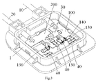
- Fig.3 shows a schematic perspective view of the photovoltaic junction box according to an exemplary embodiment of the present disclosure, wherein, a bus bar 40 has already been inserted in a positioning slot 110; however, the pressing elastic sheet 130 hasn't yet pressed against the bus bar 40
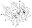
- Fig. 4 shows a schematic perspective view of the photovoltaic junction box according to an exemplary embodiment of the present disclosure, wherein, the bus bar 40 has already been inserted in the positioning slot 110, and the pressing elastic sheet 130 has already pressed against the bus bar 40.
- the photovoltaic junction box 1 mainly comprises a box body 1, two conduction terminals 100 and 200, and a diode 30.
- the conduction terminals 100 and 200 together with the diode 30 are housed in the box body 1.
- One of the conduction terminals 100 and 200 is acted as a positive conduction terminal 100, and the other of the conduction terminals 100 and 200 is acted as a negative conduction terminal 200.
- the positive conduction terminal 100 is arranged to be separated from the negative conduction terminal 200, and the diode 30 is electrically connected between the positive conduction terminal 100 and the negative conduction terminal 200.
- the positive conduction terminal 100 is electrically connected with a positive wire 10
- the negative conduction terminal 200 is electrically connected with a negative wire.
- each of the conduction terminals 100 and 200 is provided with a bus bar holding mechanism configured to holding a bus bar 40 of a solar panel (not shown) on the conduction terminal 100 or 200 so as to electrically connect the bus bar 40 to the conduction terminal 100 or 200.
- each bus bar holding mechanisms mainly comprises the positioning slot 110 and the pressing elastic sheet 130.
- the positioning slot 110 is formed on each of the conduction terminals 100 and 200, and is adapted to position the bus bar 40 inserted therein in place; and the pressing elastic sheet 130 is mounted on each of the conduction terminals 100 and 200, and is adapted to press the bus bar 40 located in the positioning slot 110 of the conduction terminal 100 or 200, so that the bus bar 40 reliably comes into electrical contact with the conduction terminal 100 or 200.
- the positioning slot 110 is defined by an internal wall surface of a recession 111 and an internal wall surface of a projection 112 both formed on a surface of the conduction terminal 100 or 200 by a punching processing.
- the pressing elastic sheet 130 has a pressing portion 132 projecting downwards and adapted to press the bus bar 40 received in the recession 111 against an internal bottom surface of the recession 111.
- a base of the pressing elastic sheet 130 is rotatably connected to the surface of the conduction terminal 100 or 200, so as to allow the pressing elastic sheet 130 to rotate between a first position and a second position.
- the pressing portion 132 of the pressing elastic sheet 130 is located in the recession 111 so as to press the bus bar 40 inserted in the positioning slot 110.
- the pressing portion 132 of the pressing elastic sheet 130 is located outside the recession 111, so as to allow to insert the bus bar 40 in the positioning slot 110 or pull the bus bar 40 out of the positioning slot 110.
- a plurality of projecting ribs 133 separated from each other are formed on a bottom surface of the pressing portion 132 of the pressing elastic sheet 130. These projecting ribs 133 is adapted to press against the bus bar 40.
- a tip portion of the pressing elastic sheet 130 is bent upwards, and is formed with a slot 135 so as to form a holding portion 134, which is adapted to be held by an operator, on the pressing elastic sheet 130.
- the operator may operate the pressing elastic sheet 130 through the holding portion 134, for example, rotating the pressing elastic sheet 130 from the second position as shown in Fig. 3 to the first position as shown in Fig. 4 .
- each of the conduction terminals 100 and 200 is provided with a stub-shaped protrusion 120, in which a thread hole 121 is formed; accordingly, a through-hole 131 is formed in the base of the pressing elastic sheet 130.
- the pressing elastic sheet 130 is rotatably connected to the conduction terminal 100 or 200 by a screw 140.
- the screw 140 passes through the through-hole 131 and is screwed in the thread hole 121 of the stub-shaped protrusion 120. In this way, the conduction terminal 100 or 200 may rotate about a smooth cylindrical base of the screw 140.
- the recession 111 has a flat internal bottom surface (an upper surface of the recession) lower than an upper surface of the conduction terminal 100 or 200.
- the projection 112 has a flat internal top surface (the lower surface as shown in Fig. 1 ) higher than the upper surface of the conduction terminal 100 or 200.
- the bus bar 40 inserted in the positioning slot 110 is defined between the lower surface of the recession 111 and the internal top surface of the projection 112.
- the internal bottom surface of the recession 111 is provided with soldering material, such as tin solder, for soldering the bus bar 40 on the internal bottom surface of the recession 111.
- soldering material such as tin solder
- the bus bar 40 is soldered on the conduction terminal 100 or 200.
- cold solder joint thus may be effectively avoided so as to improve the soldering quality.
- the projection 112 on the conduction terminal 100 or 200 is formed at one end of the recession 111 and aligned with the recession 111. In this way, the straight bus bar 40 may smoothly be inserted in the positioning slot 110 defined by the projection 112 together with the recession 111.
Landscapes
- Engineering & Computer Science (AREA)
- Architecture (AREA)
- Civil Engineering (AREA)
- Structural Engineering (AREA)
- Photovoltaic Devices (AREA)
- Connection Or Junction Boxes (AREA)
- Connections By Means Of Piercing Elements, Nuts, Or Screws (AREA)
- Connections Effected By Soldering, Adhesion, Or Permanent Deformation (AREA)
Abstract
Description
- This application claims the benefit of Chinese Patent Application No.
201510471648.1 filed on August 4, 2015 - The present disclosure relates to a photovoltaic junction box for electrically connecting with a bus bar of a solar panel, and a photovoltaic junction module comprising the photovoltaic junction box.
- In the prior art, a photovoltaic junction box generally comprises a box body; and a positive conduction terminal, a negative conduction terminal, a diode and an elastic clip, which are all housed in the box body. The diode is connected between the positive conduction terminal and the negative conduction terminal. The elastic clip is adapted to clamp a positive bus bar of the solar panel on the positive conduction terminal and at the same time clamp a negative bus bar of the solar panel on the negative conduction terminal, such that the positive and negative bus bars of the solar panel are electrically connected to the positive and negative conduction terminals, respectively.
- The current photovoltaic junction box has the drawbacks, such as complicated structure, relatively high cost and sophisticated operation.
- Further, in the current photovoltaic junction box, electrical contact between the bus bar and the conduction terminal is not reliable and quite easy to become loose.
- The object of the present disclosure is to solve the above mentioned technical problems or other technical problems of the prior art
- One object of the present disclosure is to provide a photovoltaic conduction box of simple structure, which may realize the reliable electrical connection between a bus bar of a solar panel and a conduction terminal of the photovoltaic conduction box.
- According to one aspect of the present disclosure, there is provided a photovoltaic connection box, comprising: a box body; and conduction terminals received in the box body. Each conduction terminal is provided with a bus bar holding mechanism configured to hold a bus bar of a solar panel on the conduction terminal so as to electrically connect the bus bar to the conduction terminal. Each of the bus bar holding mechanisms comprises a positioning slot formed on the conduction terminal and adapted to position the bus bar inserted therein in place; and a pressing elastic sheet mounted on the conduction terminal and adapted to press the bus bar on the conduction terminal, so that the bus bar reliably comes into electrical contact with the conduction terminal.
- According to one exemplary embodiment of the present disclosure, the positioning slot is defined by a recession and a projection both formed on a surface of the conduction terminal.
- According to a still exemplary embodiment of the present disclosure, the pressing elastic sheet has a pressing portion projecting downwards and adapted to press the bus bar received in the recession against an internal bottom surface of the recession.
- According to a still exemplary embodiment of the present disclosure, a base of the pressing elastic sheet is rotatably connected to the surface of the conduction terminal, so as to allow the pressing elastic sheet to rotate between a first position and a second position; when the pressing elastic sheet is in the first position, the pressing portion of the pressing elastic sheet is located in the recession so as to press the bus bar inserted in the positioning slot; and when the pressing elastic sheet is in the second position, the pressing portion of the pressing elastic sheet is located outside the recession, so as to allow to insert the bus bar in the positioning slot or pull the bus bar out of the positioning slot.
- According to a still exemplary embodiment of the present disclosure, a bottom surface of the pressing portion of the pressing elastic sheet is provided with a plurality of projecting ribs separated from each other and adapted to press against the bus bar.
- According to a still exemplary embodiment of the present disclosure, a tip portion of the pressing elastic sheet bends upwards and is formed with a slot so as to form a holding portion, which is adapted to be held by an operator, on the pressing elastic sheet.
- According to a still exemplary embodiment of the present disclosure, each of the conduction terminals is formed with a stub-shaped protrusion, in which a thread hole is formed, and the base of the pressing elastic sheet is formed with a through-hole; and the pressing elastic sheet is rotatably connected to the conduction terminal by a screw passing through the through-hole and screwed in the thread hole of the stub-shaped protrusion.
- According to a still exemplary embodiment of the present disclosure, the recession has a flat internal bottom surface lower than an upper surface of the conduction terminal; the projection has a flat lower surface higher than the upper surface of the conduction terminal; and the bus bar inserted in the positioning slot is defined between the internal bottom surface of the recession and the lower surface of the projection.
- According to a still exemplary embodiment of the present disclosure, the internal bottom surface of the recession is provided with soldering material for soldering the bus bar on the internal bottom surface of the recession.
- According to a still exemplary embodiment of the present disclosure, the projection is formed at one end of the recession and is aligned with the recession.
- According to a still exemplary embodiment of the present disclosure, the conduction terminals comprise a positive conduction terminal and a negative conduction terminal separated from the positive conduction terminal; and the photovoltaic connection box further comprises a diode electrically connected between the positive conduction terminal and the negative conduction terminal.
- According to a still exemplary embodiment of the present disclosure, the photovoltaic box further comprises a positive wire electrically connected to positive conduction terminal and a negative wire electrically connected to the negative conduction terminal.
- According to another aspect of the present disclosure, there is provided a photovoltaic connection module, wherein, the module comprises an above-mentioned photovoltaic connection box and a solar panel. The bus bar of the solar panel is inserted in the positioning slot so as to be held in place; and the pressing elastic sheet presses the bus bar on the conduction terminal, so that the bus bar reliably comes into electrical contact with the conduction terminal.
- According to one exemplary embodiment of the present disclosure, an internal bottom surface of the positioning slot is provided with soldering material for soldering the bus bar on the conduction terminal.
- According to a still exemplary embodiment of the present disclosure, after pressing the pressing elastic sheet on the bus bar, the bus bar is soldered on the conduction terminal.
- In the various exemplary embodiments of the present disclosure, the bus bar of the solar panel is inserted in the positioning slot of the conduction terminal so as to be held in place. The pressing elastic sheet provided on the conduction terminal presses the bus bar in the positioning slot so as to prevent the bus bar from moving with respect to the conduction terminal and keep the reliable electrical contact between the bus bar and the conduction terminal.
- Further, in some exemplary embodiments of the present disclosure, the bus bar is further soldered on the internal bottom surface of the positioning slot so as to further prevent the bus bar from moving with respect to the conduction terminal, such that the electrical connection between the bus bar and the conduction terminal will be more reliable.
- The above and other features of the present disclosure will become more apparent by describing in detail exemplary embodiments thereof with reference to the accompanying drawings, in which:
-
Fig.1 shows a schematic perspective view of conduction terminals in a photovoltaic junction box according to an exemplary embodiment of the present disclosure; -
Fig. 2 shows a schematic perspective view of a pressing elastic sheet in the photovoltaic junction box according to an exemplary embodiment of the present disclosure; -
Fig.3 shows a schematic perspective view of the photovoltaic junction box according to an exemplary embodiment of the present disclosure, wherein, a bus bar has already been inserted in a positioning slot; however, the pressing elastic sheet hasn't pressed against the bus bar; and -
Fig. 4 shows a schematic perspective view of the photovoltaic junction box according to an exemplary embodiment of the present disclosure, wherein, the bus bar has already been inserted in the positioning slot, and the pressing elastic sheet has already pressed against the bus bar. - Exemplary embodiments of the present disclosure will be described hereinafter in detail with reference to the attached drawings, wherein the like reference numerals refer to the like elements. The present disclosure may, however, be embodied in many different forms and should not be construed as being limited to the embodiment set forth herein; rather, these embodiments are provided so that the present disclosure will be thorough and complete, and will fully convey the concept of the disclosure to those skilled in the art.
- Furthermore, in the following detailed description, for purposes of explanation, numerous specific details are set forth in order to provide a thorough understanding of the disclosed embodiments. It will be apparent, however, that one or more embodiments may be practiced without these specific details. In other instances, well-known structures and devices are schematically shown in order to simplify the drawing.
- According to a general technical concept of the invention, there is provided a photovoltaic connection box, comprising: a box body; and a plurality of conduction terminals received in the box body. Each conduction terminal is provided with a bus bar holding mechanism configured to hold a bus bar of a solar panel on the conduction terminal so as to electrically connect the bus bar to the conduction terminal. Each of the bus bar holding mechanisms comprises a positioning slot formed on the conduction terminal and adapted to position the bus bar inserted therein in place; and a pressing elastic sheet mounted on the conduction terminal and adapted to press the bus bar on the conduction terminal, so that the bus bar reliably comes into electrical contact with the conduction terminal.
-
Fig.1 shows a schematic perspective view of theconduction terminals Fig. 2 shows a schematic perspective view of a pressingelastic sheet 130 in the photovoltaic junction box according to an exemplary embodiment of the present disclosure;Fig.3 shows a schematic perspective view of the photovoltaic junction box according to an exemplary embodiment of the present disclosure, wherein, abus bar 40 has already been inserted in apositioning slot 110; however, the pressingelastic sheet 130 hasn't yet pressed against thebus bar 40; andFig. 4 shows a schematic perspective view of the photovoltaic junction box according to an exemplary embodiment of the present disclosure, wherein, thebus bar 40 has already been inserted in thepositioning slot 110, and the pressingelastic sheet 130 has already pressed against thebus bar 40. - In an exemplary embodiment of the present disclosure, there is disclosed a photovoltaic junction box. As illustrated in
Figs. 3 and4 , the photovoltaic junction box 1 mainly comprises a box body 1, twoconduction terminals diode 30. - As clearly illustrated in
Fig.3 , theconduction terminals diode 30 are housed in the box body 1. One of theconduction terminals positive conduction terminal 100, and the other of theconduction terminals negative conduction terminal 200. Thepositive conduction terminal 100 is arranged to be separated from thenegative conduction terminal 200, and thediode 30 is electrically connected between thepositive conduction terminal 100 and thenegative conduction terminal 200. Thepositive conduction terminal 100 is electrically connected with apositive wire 10, and thenegative conduction terminal 200 is electrically connected with a negative wire. - As illustrated in
Figs. 1 to 4 , in an exemplary embodiment of the present disclosure, each of theconduction terminals bus bar 40 of a solar panel (not shown) on theconduction terminal bus bar 40 to theconduction terminal - Referring to
Fig.1 to Fig.4 , in an illustrated embodiment, each bus bar holding mechanisms mainly comprises thepositioning slot 110 and the pressingelastic sheet 130. - As clearly illustrated in
Figs. 1 ,3 and4 , thepositioning slot 110 is formed on each of theconduction terminals bus bar 40 inserted therein in place; and the pressingelastic sheet 130 is mounted on each of theconduction terminals bus bar 40 located in thepositioning slot 110 of theconduction terminal bus bar 40 reliably comes into electrical contact with theconduction terminal - As clearly illustrated in
Figs.1 ,3 and4 , thepositioning slot 110 is defined by an internal wall surface of arecession 111 and an internal wall surface of aprojection 112 both formed on a surface of theconduction terminal - As clearly illustrated in
Figs.2 ,3 and4 , the pressingelastic sheet 130 has a pressingportion 132 projecting downwards and adapted to press thebus bar 40 received in therecession 111 against an internal bottom surface of therecession 111. - As illustrated in
Fig.1 to Fig.4 , in the illustrated embodiment, a base of the pressingelastic sheet 130 is rotatably connected to the surface of theconduction terminal elastic sheet 130 to rotate between a first position and a second position. - When the pressing
elastic sheet 130 is in the first position (the position as illustrated inFig.4 ), thepressing portion 132 of the pressingelastic sheet 130 is located in therecession 111 so as to press thebus bar 40 inserted in thepositioning slot 110. - When the pressing
elastic sheet 130 is in the second position (the position as illustrated inFig.3 ), thepressing portion 132 of the pressingelastic sheet 130 is located outside therecession 111, so as to allow to insert thebus bar 40 in thepositioning slot 110 or pull thebus bar 40 out of thepositioning slot 110. - As illustrated in
Figs.2 and4 , in the illustrated embodiment, a plurality of projectingribs 133 separated from each other are formed on a bottom surface of thepressing portion 132 of the pressingelastic sheet 130. These projectingribs 133 is adapted to press against thebus bar 40. - In this way, it is possible to more reliably press the bus bars 40 on the
conduction terminals ribs 133 come into contact with thebus bar 40, the contact resistance between the pressingelastic sheet 130 and thebus bar 40 is reduced. - As clearly illustrated in
Fig.2 , in the illustrated embodiment, a tip portion of the pressingelastic sheet 130 is bent upwards, and is formed with aslot 135 so as to form a holdingportion 134, which is adapted to be held by an operator, on the pressingelastic sheet 130. In this way, the operator may operate the pressingelastic sheet 130 through the holdingportion 134, for example, rotating the pressingelastic sheet 130 from the second position as shown inFig. 3 to the first position as shown inFig. 4 . - As illustrated from
Fig.1 to Fig.4 , in an exemplary embodiment of the present disclosure, each of theconduction terminals protrusion 120, in which athread hole 121 is formed; accordingly, a through-hole 131 is formed in the base of the pressingelastic sheet 130. The pressingelastic sheet 130 is rotatably connected to theconduction terminal screw 140. Thescrew 140 passes through the through-hole 131 and is screwed in thethread hole 121 of the stub-shapedprotrusion 120. In this way, theconduction terminal screw 140. - As illustrated in
Figs.1 and3 , in an exemplary embodiment of the present disclosure, therecession 111 has a flat internal bottom surface (an upper surface of the recession) lower than an upper surface of theconduction terminal projection 112 has a flat internal top surface (the lower surface as shown inFig. 1 ) higher than the upper surface of theconduction terminal bus bar 40 inserted in thepositioning slot 110 is defined between the lower surface of therecession 111 and the internal top surface of theprojection 112. - In an exemplary embodiment of the present disclosure, the internal bottom surface of the
recession 111 is provided with soldering material, such as tin solder, for soldering thebus bar 40 on the internal bottom surface of therecession 111. In this way, it is possible to further prevent thebus bar 40 from moving with respect to theconduction terminal bus bar 40 and theconduction terminal - In an exemplary embodiment of the present disclosure, after pressing the pressing
elastic sheet 130 on thebus bar 40, thebus bar 40 is soldered on theconduction terminal bus bar 40 has already been tightly pressed on the flat internal bottom surface of therecession 111 by the pressingelastic sheet 130, cold solder joint thus may be effectively avoided so as to improve the soldering quality. - As illustrated in
Figs. 1 and3 , in the illustrated embodiment, theprojection 112 on theconduction terminal recession 111 and aligned with therecession 111. In this way, thestraight bus bar 40 may smoothly be inserted in thepositioning slot 110 defined by theprojection 112 together with therecession 111. - It should be appreciated for those skilled in this art that the above embodiments are all exemplary embodiments, and many modifications may be made to the above embodiments by those skilled in this art, and various features described in different embodiments may be freely combined with each other without conflicting in configuration or principle.
- Although the present disclosure has been described with reference to the attached drawings, the embodiments disclosed in the attached drawings are intended to describe the preferred embodiments of the present disclosure exemplarily, but should not be construed as a limitation to the present disclosure.
- Although several embodiments of the general concept of the present disclosure have been shown and described, it would be appreciated by those skilled in the art that various changes or modifications may be made in these embodiments without departing from the principles and spirit of the disclosure, the scope of which is defined in the claims and their equivalents.
- As used herein, term "comprising" or "having" should be understood as not excluding other elements or steps, and term "a" or "an" should be understood as not excluding plural elements or steps. In addition, any reference numeral in claims should not be understood as the limitation of the scope of the present disclosure.
Claims (15)
- A photovoltaic connection box, comprising:a box body;a plurality of conduction terminals received in the box body; anda plurality of bus bar holding mechanisms provided on the conduction terminals, and configured to hold bus bars of a solar panel on the conduction terminals, respectively, so as to electrically connect the bus bars to the conduction terminals, each bus bar holding mechanisms comprising:a positioning slot formed on the conduction terminal and adapted to position the bus bar inserted therein in place; anda pressing elastic sheet mounted on the conduction terminal and adapted to press the bus bar on the conduction terminal, so that the bus bar reliably comes into electrical contact with the conduction terminal.
- The photovoltaic connection box according to claim 1, wherein the positioning slot is defined by a recession and a projection both formed on a surface of the conduction terminal.
- The photovoltaic connection box according to claim 2, wherein the pressing elastic sheet has a pressing portion projecting downwards and adapted to press the bus bar received in the recession against an internal bottom surface of the recession.
- The photovoltaic connection box according to claim 3, wherein, a base of the pressing elastic sheet is rotatably connected to the surface of the conduction terminal, so as to allow the pressing elastic sheet to rotate between a first position and a second position;
when the pressing elastic sheet is in the first position, the pressing portion of the pressing elastic sheet is located in the recession so as to press the bus bar inserted in the positioning slot; and
when the pressing elastic sheet is in the second position, the pressing portion of the pressing elastic sheet is located outside the recession, so as to allow to insert the bus bar in the positioning slot or pull the bus bar out of the positioning slot. - The photovoltaic connection box according to claim 4, wherein, a bottom surface of the pressing portion of the pressing elastic sheet is provided with a plurality of projecting ribs separated from each other and adapted to press against the bus bar.
- The photovoltaic connection box according to claim 5, wherein a tip portion of the pressing elastic sheet is bent upwards and is formed with a slot so as to form a holding portion, which is adapted to be held by an operator, on the pressing elastic sheet.
- The photovoltaic connection box according to claim 4, wherein
each of the conduction terminals is formed with a stub-shaped protrusion, in which a thread hole is formed, and the base of the pressing elastic sheet is formed with a through-hole; and
the pressing elastic sheet is rotatably connected to the conduction terminal by a screw passing through the through-hole and screwed in the thread hole of the stub-shaped protrusion. - The photovoltaic connection box according to claim 7, wherein
the recession has a flat internal bottom surface lower than an upper surface of the conduction terminal;
the projection has a flat lower surface higher than the upper surface of the conduction terminal; and
the bus bar inserted in the positioning slot is defined between the internal bottom surface of the recession and the lower surface of the projection. - The photovoltaic connection box according to claim 8, wherein,
the internal bottom surface of the recession is provided with soldering material for soldering the bus bar on the internal bottom surface of the recession. - The photovoltaic connection box according to claim 9, wherein,
the projection is formed at one end of the recession and is aligned with the recession. - The photovoltaic connection box according to claim 1, wherein,
the conduction terminals comprise a positive conduction terminal and a negative conduction terminal separated from the positive conduction terminal; and
the photovoltaic connection box further comprises a diode electrically connected between the positive conduction terminal and the negative conduction terminal. - The photovoltaic connection box according to claim 1, wherein
the photovoltaic box further comprises a positive wire electrically connected to positive conduction terminal and a negative wire electrically connected to the negative conduction terminal. - A photovoltaic connection module, wherein, the module comprises:a photovoltaic connection box according to claim 1-; anda solar panel,wherein the bus bar of the solar panel is inserted in the positioning slot so as to be held in place; andwherein the pressing elastic sheet is arranged to press the bus bar on the conduction terminal, so that the bus bar reliably comes into electrical contact with the conduction terminal.
- The photovoltaic connection module according to claim 13, wherein,
an internal bottom surface of the positioning slot is provided with soldering material for soldering the bus bar on the conduction terminal. - The photovoltaic connection module according to claim 14, wherein,
after pressing the pressing elastic sheet on the bus bar, the bus bar is soldered on the conduction terminal.
Applications Claiming Priority (1)
| Application Number | Priority Date | Filing Date | Title |
|---|---|---|---|
| CN201510471648.1A CN107040202A (en) | 2015-08-04 | 2015-08-04 | Photovoltaic junction box and photovoltaic connector assembly |
Publications (2)
| Publication Number | Publication Date |
|---|---|
| EP3128629A1 true EP3128629A1 (en) | 2017-02-08 |
| EP3128629B1 EP3128629B1 (en) | 2020-07-29 |
Family
ID=56615860
Family Applications (1)
| Application Number | Title | Priority Date | Filing Date |
|---|---|---|---|
| EP16182400.8A Active EP3128629B1 (en) | 2015-08-04 | 2016-08-02 | Photovoltaic junction box and photovoltaic junction module |
Country Status (5)
| Country | Link |
|---|---|
| US (1) | US20170040938A1 (en) |
| EP (1) | EP3128629B1 (en) |
| JP (1) | JP6820681B2 (en) |
| CN (1) | CN107040202A (en) |
| ES (1) | ES2824164T3 (en) |
Cited By (3)
| Publication number | Priority date | Publication date | Assignee | Title |
|---|---|---|---|---|
| CN105763152A (en) * | 2016-03-15 | 2016-07-13 | 浙江昱能科技有限公司 | Conjunction box, and photovoltaic assembly and system thereof |
| CN107749740A (en) * | 2017-11-06 | 2018-03-02 | 成都中建材光电材料有限公司 | A kind of solar battery connecting box and its frock |
| CN110892534A (en) * | 2017-07-14 | 2020-03-17 | 联邦科学和工业研究组织 | Photovoltaic device and method |
Families Citing this family (9)
| Publication number | Priority date | Publication date | Assignee | Title |
|---|---|---|---|---|
| JP2017524326A (en) * | 2014-07-25 | 2017-08-24 | マルチ−ホールディング アーゲー | Junction box for solar cell module |
| USD862380S1 (en) * | 2017-07-27 | 2019-10-08 | Sungrow Power Supply Co., Ltd. | Power optimizer |
| CN109473382B (en) * | 2018-11-12 | 2025-01-10 | 江苏创基新能源有限公司 | Solar photovoltaic module back panel threading tool |
| CN111726074A (en) * | 2020-07-29 | 2020-09-29 | 苏州快可光伏电子股份有限公司 | Improved Modular PV Module Bypass Element and Module Junction Box |
| JP1706411S (en) * | 2021-03-30 | 2022-02-01 | Wire pull-in tool | |
| CN113258343A (en) * | 2021-06-03 | 2021-08-13 | 惠州领越光电技术有限公司 | Integrated positive and negative electrode connector |
| CN115296612B (en) * | 2022-10-08 | 2022-12-27 | 赫冉新能源科技(扬州)有限公司 | Photovoltaic module junction box and photovoltaic module |
| USD1113724S1 (en) * | 2024-04-09 | 2026-02-17 | Hiconics Eco-Energy Drive Technology Co., Ltd. | Photovoltaic power optimizer |
| CN120567030B (en) * | 2025-06-04 | 2026-03-31 | 世地光伏科技(泰州)有限公司 | A photovoltaic junction box for offshore photovoltaic modules |
Citations (5)
| Publication number | Priority date | Publication date | Assignee | Title |
|---|---|---|---|---|
| EP2330634A2 (en) * | 2009-12-03 | 2011-06-08 | Hosiden Corporation | Terminal box for solar cell module |
| US7972177B2 (en) * | 2008-05-03 | 2011-07-05 | Lumberg Connect Gmbh | Slide clip |
| EP2434549A1 (en) * | 2009-05-20 | 2012-03-28 | Yukita Electric Wire Co., Ltd. | Connecting terminal, terminal connecting structure and terminal box |
| CN202190230U (en) * | 2011-09-23 | 2012-04-11 | 昆山捷讯腾精密电子科技有限公司 | Solar photovoltaic connecting box |
| KR101483594B1 (en) * | 2013-09-17 | 2015-01-19 | 신선숙 | One touch junction box for high efficiency photovoltaic modules |
Family Cites Families (6)
| Publication number | Priority date | Publication date | Assignee | Title |
|---|---|---|---|---|
| US7938661B2 (en) * | 2008-10-29 | 2011-05-10 | Tyco Electronics Corporation | Photovoltaic module connector assembly |
| KR101110925B1 (en) * | 2010-01-21 | 2012-03-13 | 엘에스전선 주식회사 | Ribbon wire connection device for junction box of solar cell panel and junction box having the same |
| US20120067613A1 (en) * | 2010-09-17 | 2012-03-22 | Delta Electronics, Inc. | Junction box and conductor strip connection device thereof |
| CN201904356U (en) * | 2010-12-23 | 2011-07-20 | 深圳市锐莱科新能源科技有限公司 | Clamping structure for bus-bar of solar junction box |
| CN201910434U (en) * | 2010-12-30 | 2011-07-27 | 光为绿色新能源有限公司 | Junction box for solar photovoltaic cells |
| CN202601667U (en) * | 2012-04-16 | 2012-12-12 | 苏州快可光伏电子股份有限公司 | Wiring box |
-
2015
- 2015-08-04 CN CN201510471648.1A patent/CN107040202A/en active Pending
-
2016
- 2016-07-29 JP JP2016149318A patent/JP6820681B2/en not_active Expired - Fee Related
- 2016-08-02 US US15/225,906 patent/US20170040938A1/en not_active Abandoned
- 2016-08-02 ES ES16182400T patent/ES2824164T3/en active Active
- 2016-08-02 EP EP16182400.8A patent/EP3128629B1/en active Active
Patent Citations (5)
| Publication number | Priority date | Publication date | Assignee | Title |
|---|---|---|---|---|
| US7972177B2 (en) * | 2008-05-03 | 2011-07-05 | Lumberg Connect Gmbh | Slide clip |
| EP2434549A1 (en) * | 2009-05-20 | 2012-03-28 | Yukita Electric Wire Co., Ltd. | Connecting terminal, terminal connecting structure and terminal box |
| EP2330634A2 (en) * | 2009-12-03 | 2011-06-08 | Hosiden Corporation | Terminal box for solar cell module |
| CN202190230U (en) * | 2011-09-23 | 2012-04-11 | 昆山捷讯腾精密电子科技有限公司 | Solar photovoltaic connecting box |
| KR101483594B1 (en) * | 2013-09-17 | 2015-01-19 | 신선숙 | One touch junction box for high efficiency photovoltaic modules |
Cited By (4)
| Publication number | Priority date | Publication date | Assignee | Title |
|---|---|---|---|---|
| CN105763152A (en) * | 2016-03-15 | 2016-07-13 | 浙江昱能科技有限公司 | Conjunction box, and photovoltaic assembly and system thereof |
| CN110892534A (en) * | 2017-07-14 | 2020-03-17 | 联邦科学和工业研究组织 | Photovoltaic device and method |
| CN110892534B (en) * | 2017-07-14 | 2023-07-11 | 联邦科学和工业研究组织 | Photovoltaic device and method |
| CN107749740A (en) * | 2017-11-06 | 2018-03-02 | 成都中建材光电材料有限公司 | A kind of solar battery connecting box and its frock |
Also Published As
| Publication number | Publication date |
|---|---|
| JP6820681B2 (en) | 2021-01-27 |
| US20170040938A1 (en) | 2017-02-09 |
| ES2824164T3 (en) | 2021-05-11 |
| JP2017038512A (en) | 2017-02-16 |
| EP3128629B1 (en) | 2020-07-29 |
| CN107040202A (en) | 2017-08-11 |
Similar Documents
| Publication | Publication Date | Title |
|---|---|---|
| EP3128629B1 (en) | Photovoltaic junction box and photovoltaic junction module | |
| EP3059807B1 (en) | Connection terminal | |
| EP3203583A1 (en) | Wire connection terminal structure | |
| US9502795B1 (en) | Clamping wire structure of terminal block | |
| US9466897B1 (en) | Double-wire terminal block structure | |
| EP3136512A1 (en) | Connector | |
| US9624951B2 (en) | Connection terminal structure | |
| US9825378B2 (en) | Mounting clip | |
| EP2843767A1 (en) | Coaxial connector and connecting terminal thereof | |
| EP3407428A1 (en) | Metal leaf spring structure of electrical connection terminal | |
| US10651571B2 (en) | Metal leaf spring protection structure of electrical connection terminal | |
| JP5836827B2 (en) | Input terminal block | |
| EP2418738B1 (en) | Terminal for connecting wires to printed circuit boards | |
| EP3407427B1 (en) | Metal leaf spring structure of electrical connection terminal | |
| US20240079805A1 (en) | Insulating piercing contact with wire retention feature | |
| CN207543456U (en) | One kind is used for the fixed erecting device of electrical equipment | |
| CN211126098U (en) | Wiring terminal inlet wire structure | |
| CN205335451U (en) | Connector | |
| CN211670345U (en) | Wire-to-board connector suitable for wires of different sizes | |
| CN204407524U (en) | Duckbill type terminal | |
| US9859637B2 (en) | Electrical connector | |
| CN106711652B (en) | Improved wiring terminal | |
| CN213278429U (en) | Wiring piece and motor thereof | |
| CN207199868U (en) | Push-type electrical connector for surface mounting and lamps using the push-type electrical connector | |
| US20130078862A1 (en) | Card edge connector |
Legal Events
| Date | Code | Title | Description |
|---|---|---|---|
| PUAI | Public reference made under article 153(3) epc to a published international application that has entered the european phase |
Free format text: ORIGINAL CODE: 0009012 |
|
| STAA | Information on the status of an ep patent application or granted ep patent |
Free format text: STATUS: THE APPLICATION HAS BEEN PUBLISHED |
|
| AK | Designated contracting states |
Kind code of ref document: A1 Designated state(s): AL AT BE BG CH CY CZ DE DK EE ES FI FR GB GR HR HU IE IS IT LI LT LU LV MC MK MT NL NO PL PT RO RS SE SI SK SM TR |
|
| AX | Request for extension of the european patent |
Extension state: BA ME |
|
| STAA | Information on the status of an ep patent application or granted ep patent |
Free format text: STATUS: REQUEST FOR EXAMINATION WAS MADE |
|
| 17P | Request for examination filed |
Effective date: 20170808 |
|
| RBV | Designated contracting states (corrected) |
Designated state(s): AL AT BE BG CH CY CZ DE DK EE ES FI FR GB GR HR HU IE IS IT LI LT LU LV MC MK MT NL NO PL PT RO RS SE SI SK SM TR |
|
| STAA | Information on the status of an ep patent application or granted ep patent |
Free format text: STATUS: EXAMINATION IS IN PROGRESS |
|
| 17Q | First examination report despatched |
Effective date: 20171026 |
|
| REG | Reference to a national code |
Ref country code: DE Ref legal event code: R079 Ref document number: 602016040701 Country of ref document: DE Free format text: PREVIOUS MAIN CLASS: H02G0003080000 Ipc: H02G0003180000 |
|
| RIC1 | Information provided on ipc code assigned before grant |
Ipc: H02G 3/18 20060101AFI20190301BHEP Ipc: H02S 40/34 20140101ALI20190301BHEP Ipc: H01L 31/02 20060101ALI20190301BHEP |
|
| GRAP | Despatch of communication of intention to grant a patent |
Free format text: ORIGINAL CODE: EPIDOSNIGR1 |
|
| STAA | Information on the status of an ep patent application or granted ep patent |
Free format text: STATUS: GRANT OF PATENT IS INTENDED |
|
| INTG | Intention to grant announced |
Effective date: 20200320 |
|
| GRAS | Grant fee paid |
Free format text: ORIGINAL CODE: EPIDOSNIGR3 |
|
| GRAA | (expected) grant |
Free format text: ORIGINAL CODE: 0009210 |
|
| STAA | Information on the status of an ep patent application or granted ep patent |
Free format text: STATUS: THE PATENT HAS BEEN GRANTED |
|
| AK | Designated contracting states |
Kind code of ref document: B1 Designated state(s): AL AT BE BG CH CY CZ DE DK EE ES FI FR GB GR HR HU IE IS IT LI LT LU LV MC MK MT NL NO PL PT RO RS SE SI SK SM TR |
|
| REG | Reference to a national code |
Ref country code: CH Ref legal event code: EP |
|
| REG | Reference to a national code |
Ref country code: AT Ref legal event code: REF Ref document number: 1296910 Country of ref document: AT Kind code of ref document: T Effective date: 20200815 |
|
| REG | Reference to a national code |
Ref country code: IE Ref legal event code: FG4D |
|
| REG | Reference to a national code |
Ref country code: DE Ref legal event code: R096 Ref document number: 602016040701 Country of ref document: DE |
|
| REG | Reference to a national code |
Ref country code: NL Ref legal event code: FP |
|
| REG | Reference to a national code |
Ref country code: LT Ref legal event code: MG4D |
|
| REG | Reference to a national code |
Ref country code: GR Ref legal event code: EP Ref document number: 20200402802 Country of ref document: GR Effective date: 20201116 |
|
| REG | Reference to a national code |
Ref country code: AT Ref legal event code: MK05 Ref document number: 1296910 Country of ref document: AT Kind code of ref document: T Effective date: 20200729 |
|
| PG25 | Lapsed in a contracting state [announced via postgrant information from national office to epo] |
Ref country code: FI Free format text: LAPSE BECAUSE OF FAILURE TO SUBMIT A TRANSLATION OF THE DESCRIPTION OR TO PAY THE FEE WITHIN THE PRESCRIBED TIME-LIMIT Effective date: 20200729 Ref country code: PT Free format text: LAPSE BECAUSE OF FAILURE TO SUBMIT A TRANSLATION OF THE DESCRIPTION OR TO PAY THE FEE WITHIN THE PRESCRIBED TIME-LIMIT Effective date: 20201130 Ref country code: HR Free format text: LAPSE BECAUSE OF FAILURE TO SUBMIT A TRANSLATION OF THE DESCRIPTION OR TO PAY THE FEE WITHIN THE PRESCRIBED TIME-LIMIT Effective date: 20200729 Ref country code: LT Free format text: LAPSE BECAUSE OF FAILURE TO SUBMIT A TRANSLATION OF THE DESCRIPTION OR TO PAY THE FEE WITHIN THE PRESCRIBED TIME-LIMIT Effective date: 20200729 Ref country code: NO Free format text: LAPSE BECAUSE OF FAILURE TO SUBMIT A TRANSLATION OF THE DESCRIPTION OR TO PAY THE FEE WITHIN THE PRESCRIBED TIME-LIMIT Effective date: 20201029 Ref country code: BG Free format text: LAPSE BECAUSE OF FAILURE TO SUBMIT A TRANSLATION OF THE DESCRIPTION OR TO PAY THE FEE WITHIN THE PRESCRIBED TIME-LIMIT Effective date: 20201029 Ref country code: SE Free format text: LAPSE BECAUSE OF FAILURE TO SUBMIT A TRANSLATION OF THE DESCRIPTION OR TO PAY THE FEE WITHIN THE PRESCRIBED TIME-LIMIT Effective date: 20200729 Ref country code: AT Free format text: LAPSE BECAUSE OF FAILURE TO SUBMIT A TRANSLATION OF THE DESCRIPTION OR TO PAY THE FEE WITHIN THE PRESCRIBED TIME-LIMIT Effective date: 20200729 |
|
| PG25 | Lapsed in a contracting state [announced via postgrant information from national office to epo] |
Ref country code: RS Free format text: LAPSE BECAUSE OF FAILURE TO SUBMIT A TRANSLATION OF THE DESCRIPTION OR TO PAY THE FEE WITHIN THE PRESCRIBED TIME-LIMIT Effective date: 20200729 Ref country code: LV Free format text: LAPSE BECAUSE OF FAILURE TO SUBMIT A TRANSLATION OF THE DESCRIPTION OR TO PAY THE FEE WITHIN THE PRESCRIBED TIME-LIMIT Effective date: 20200729 Ref country code: PL Free format text: LAPSE BECAUSE OF FAILURE TO SUBMIT A TRANSLATION OF THE DESCRIPTION OR TO PAY THE FEE WITHIN THE PRESCRIBED TIME-LIMIT Effective date: 20200729 Ref country code: IS Free format text: LAPSE BECAUSE OF FAILURE TO SUBMIT A TRANSLATION OF THE DESCRIPTION OR TO PAY THE FEE WITHIN THE PRESCRIBED TIME-LIMIT Effective date: 20201129 |
|
| PG25 | Lapsed in a contracting state [announced via postgrant information from national office to epo] |
Ref country code: EE Free format text: LAPSE BECAUSE OF FAILURE TO SUBMIT A TRANSLATION OF THE DESCRIPTION OR TO PAY THE FEE WITHIN THE PRESCRIBED TIME-LIMIT Effective date: 20200729 Ref country code: RO Free format text: LAPSE BECAUSE OF FAILURE TO SUBMIT A TRANSLATION OF THE DESCRIPTION OR TO PAY THE FEE WITHIN THE PRESCRIBED TIME-LIMIT Effective date: 20200729 Ref country code: SM Free format text: LAPSE BECAUSE OF FAILURE TO SUBMIT A TRANSLATION OF THE DESCRIPTION OR TO PAY THE FEE WITHIN THE PRESCRIBED TIME-LIMIT Effective date: 20200729 Ref country code: DK Free format text: LAPSE BECAUSE OF FAILURE TO SUBMIT A TRANSLATION OF THE DESCRIPTION OR TO PAY THE FEE WITHIN THE PRESCRIBED TIME-LIMIT Effective date: 20200729 Ref country code: CZ Free format text: LAPSE BECAUSE OF NON-PAYMENT OF DUE FEES Effective date: 20200802 Ref country code: MC Free format text: LAPSE BECAUSE OF FAILURE TO SUBMIT A TRANSLATION OF THE DESCRIPTION OR TO PAY THE FEE WITHIN THE PRESCRIBED TIME-LIMIT Effective date: 20200729 Ref country code: LU Free format text: LAPSE BECAUSE OF NON-PAYMENT OF DUE FEES Effective date: 20200802 |
|
| REG | Reference to a national code |
Ref country code: DE Ref legal event code: R097 Ref document number: 602016040701 Country of ref document: DE |
|
| REG | Reference to a national code |
Ref country code: ES Ref legal event code: FG2A Ref document number: 2824164 Country of ref document: ES Kind code of ref document: T3 Effective date: 20210511 |
|
| REG | Reference to a national code |
Ref country code: BE Ref legal event code: MM Effective date: 20200831 |
|
| PG25 | Lapsed in a contracting state [announced via postgrant information from national office to epo] |
Ref country code: AL Free format text: LAPSE BECAUSE OF FAILURE TO SUBMIT A TRANSLATION OF THE DESCRIPTION OR TO PAY THE FEE WITHIN THE PRESCRIBED TIME-LIMIT Effective date: 20200729 |
|
| PLBE | No opposition filed within time limit |
Free format text: ORIGINAL CODE: 0009261 |
|
| STAA | Information on the status of an ep patent application or granted ep patent |
Free format text: STATUS: NO OPPOSITION FILED WITHIN TIME LIMIT |
|
| PG25 | Lapsed in a contracting state [announced via postgrant information from national office to epo] |
Ref country code: SK Free format text: LAPSE BECAUSE OF FAILURE TO SUBMIT A TRANSLATION OF THE DESCRIPTION OR TO PAY THE FEE WITHIN THE PRESCRIBED TIME-LIMIT Effective date: 20200729 |
|
| 26N | No opposition filed |
Effective date: 20210430 |
|
| PG25 | Lapsed in a contracting state [announced via postgrant information from national office to epo] |
Ref country code: BE Free format text: LAPSE BECAUSE OF NON-PAYMENT OF DUE FEES Effective date: 20200831 Ref country code: SI Free format text: LAPSE BECAUSE OF FAILURE TO SUBMIT A TRANSLATION OF THE DESCRIPTION OR TO PAY THE FEE WITHIN THE PRESCRIBED TIME-LIMIT Effective date: 20200729 Ref country code: IE Free format text: LAPSE BECAUSE OF NON-PAYMENT OF DUE FEES Effective date: 20200802 |
|
| PG25 | Lapsed in a contracting state [announced via postgrant information from national office to epo] |
Ref country code: MT Free format text: LAPSE BECAUSE OF FAILURE TO SUBMIT A TRANSLATION OF THE DESCRIPTION OR TO PAY THE FEE WITHIN THE PRESCRIBED TIME-LIMIT Effective date: 20200729 Ref country code: CY Free format text: LAPSE BECAUSE OF FAILURE TO SUBMIT A TRANSLATION OF THE DESCRIPTION OR TO PAY THE FEE WITHIN THE PRESCRIBED TIME-LIMIT Effective date: 20200729 |
|
| PG25 | Lapsed in a contracting state [announced via postgrant information from national office to epo] |
Ref country code: MK Free format text: LAPSE BECAUSE OF FAILURE TO SUBMIT A TRANSLATION OF THE DESCRIPTION OR TO PAY THE FEE WITHIN THE PRESCRIBED TIME-LIMIT Effective date: 20200729 |
|
| PGFP | Annual fee paid to national office [announced via postgrant information from national office to epo] |
Ref country code: NL Payment date: 20230614 Year of fee payment: 8 Ref country code: FR Payment date: 20230608 Year of fee payment: 8 |
|
| PGFP | Annual fee paid to national office [announced via postgrant information from national office to epo] |
Ref country code: TR Payment date: 20230801 Year of fee payment: 8 Ref country code: IT Payment date: 20230711 Year of fee payment: 8 Ref country code: GB Payment date: 20230608 Year of fee payment: 8 Ref country code: ES Payment date: 20230905 Year of fee payment: 8 Ref country code: CH Payment date: 20230901 Year of fee payment: 8 |
|
| PGFP | Annual fee paid to national office [announced via postgrant information from national office to epo] |
Ref country code: GR Payment date: 20230713 Year of fee payment: 8 Ref country code: DE Payment date: 20230607 Year of fee payment: 8 |
|
| REG | Reference to a national code |
Ref country code: DE Ref legal event code: R119 Ref document number: 602016040701 Country of ref document: DE |
|
| REG | Reference to a national code |
Ref country code: CH Ref legal event code: PL |
|
| REG | Reference to a national code |
Ref country code: NL Ref legal event code: MM Effective date: 20240901 |
|
| GBPC | Gb: european patent ceased through non-payment of renewal fee |
Effective date: 20240802 |
|
| PG25 | Lapsed in a contracting state [announced via postgrant information from national office to epo] |
Ref country code: CH Free format text: LAPSE BECAUSE OF NON-PAYMENT OF DUE FEES Effective date: 20240831 Ref country code: GR Free format text: LAPSE BECAUSE OF NON-PAYMENT OF DUE FEES Effective date: 20250306 |
|
| PG25 | Lapsed in a contracting state [announced via postgrant information from national office to epo] |
Ref country code: NL Free format text: LAPSE BECAUSE OF NON-PAYMENT OF DUE FEES Effective date: 20240901 |
|
| PG25 | Lapsed in a contracting state [announced via postgrant information from national office to epo] |
Ref country code: DE Free format text: LAPSE BECAUSE OF NON-PAYMENT OF DUE FEES Effective date: 20250301 |
|
| PG25 | Lapsed in a contracting state [announced via postgrant information from national office to epo] |
Ref country code: GB Free format text: LAPSE BECAUSE OF NON-PAYMENT OF DUE FEES Effective date: 20240802 |
|
| PG25 | Lapsed in a contracting state [announced via postgrant information from national office to epo] |
Ref country code: IT Free format text: LAPSE BECAUSE OF NON-PAYMENT OF DUE FEES Effective date: 20240802 |
|
| PG25 | Lapsed in a contracting state [announced via postgrant information from national office to epo] |
Ref country code: FR Free format text: LAPSE BECAUSE OF NON-PAYMENT OF DUE FEES Effective date: 20240831 |
|
| REG | Reference to a national code |
Ref country code: ES Ref legal event code: FD2A Effective date: 20250926 |
|
| PG25 | Lapsed in a contracting state [announced via postgrant information from national office to epo] |
Ref country code: ES Free format text: LAPSE BECAUSE OF NON-PAYMENT OF DUE FEES Effective date: 20240803 |