EP3128614A1 - Electrical terminal - Google Patents
Electrical terminal Download PDFInfo
- Publication number
- EP3128614A1 EP3128614A1 EP16182270.5A EP16182270A EP3128614A1 EP 3128614 A1 EP3128614 A1 EP 3128614A1 EP 16182270 A EP16182270 A EP 16182270A EP 3128614 A1 EP3128614 A1 EP 3128614A1
- Authority
- EP
- European Patent Office
- Prior art keywords
- contact
- electrical terminal
- coupling member
- core
- crimping portion
- Prior art date
- Legal status (The legal status is an assumption and is not a legal conclusion. Google has not performed a legal analysis and makes no representation as to the accuracy of the status listed.)
- Granted
Links
Images



Classifications
-
- H—ELECTRICITY
- H01—ELECTRIC ELEMENTS
- H01R—ELECTRICALLY-CONDUCTIVE CONNECTIONS; STRUCTURAL ASSOCIATIONS OF A PLURALITY OF MUTUALLY-INSULATED ELECTRICAL CONNECTING ELEMENTS; COUPLING DEVICES; CURRENT COLLECTORS
- H01R13/00—Details of coupling devices of the kinds covered by groups H01R12/70 or H01R24/00 - H01R33/00
- H01R13/02—Contact members
- H01R13/03—Contact members characterised by the material, e.g. plating, or coating materials
-
- H—ELECTRICITY
- H01—ELECTRIC ELEMENTS
- H01R—ELECTRICALLY-CONDUCTIVE CONNECTIONS; STRUCTURAL ASSOCIATIONS OF A PLURALITY OF MUTUALLY-INSULATED ELECTRICAL CONNECTING ELEMENTS; COUPLING DEVICES; CURRENT COLLECTORS
- H01R13/00—Details of coupling devices of the kinds covered by groups H01R12/70 or H01R24/00 - H01R33/00
- H01R13/02—Contact members
-
- H—ELECTRICITY
- H01—ELECTRIC ELEMENTS
- H01R—ELECTRICALLY-CONDUCTIVE CONNECTIONS; STRUCTURAL ASSOCIATIONS OF A PLURALITY OF MUTUALLY-INSULATED ELECTRICAL CONNECTING ELEMENTS; COUPLING DEVICES; CURRENT COLLECTORS
- H01R13/00—Details of coupling devices of the kinds covered by groups H01R12/70 or H01R24/00 - H01R33/00
- H01R13/02—Contact members
- H01R13/025—Contact members formed by the conductors of a cable end
-
- H—ELECTRICITY
- H01—ELECTRIC ELEMENTS
- H01R—ELECTRICALLY-CONDUCTIVE CONNECTIONS; STRUCTURAL ASSOCIATIONS OF A PLURALITY OF MUTUALLY-INSULATED ELECTRICAL CONNECTING ELEMENTS; COUPLING DEVICES; CURRENT COLLECTORS
- H01R13/00—Details of coupling devices of the kinds covered by groups H01R12/70 or H01R24/00 - H01R33/00
- H01R13/02—Contact members
- H01R13/04—Pins or blades for co-operation with sockets
- H01R13/05—Resilient pins or blades
- H01R13/052—Resilient pins or blades co-operating with sockets having a circular transverse section
-
- H—ELECTRICITY
- H01—ELECTRIC ELEMENTS
- H01R—ELECTRICALLY-CONDUCTIVE CONNECTIONS; STRUCTURAL ASSOCIATIONS OF A PLURALITY OF MUTUALLY-INSULATED ELECTRICAL CONNECTING ELEMENTS; COUPLING DEVICES; CURRENT COLLECTORS
- H01R13/00—Details of coupling devices of the kinds covered by groups H01R12/70 or H01R24/00 - H01R33/00
- H01R13/02—Contact members
- H01R13/04—Pins or blades for co-operation with sockets
- H01R13/05—Resilient pins or blades
- H01R13/055—Resilient pins or blades co-operating with sockets having a rectangular transverse section
-
- H—ELECTRICITY
- H01—ELECTRIC ELEMENTS
- H01R—ELECTRICALLY-CONDUCTIVE CONNECTIONS; STRUCTURAL ASSOCIATIONS OF A PLURALITY OF MUTUALLY-INSULATED ELECTRICAL CONNECTING ELEMENTS; COUPLING DEVICES; CURRENT COLLECTORS
- H01R13/00—Details of coupling devices of the kinds covered by groups H01R12/70 or H01R24/00 - H01R33/00
- H01R13/02—Contact members
- H01R13/10—Sockets for co-operation with pins or blades
- H01R13/11—Resilient sockets
- H01R13/113—Resilient sockets co-operating with pins or blades having a rectangular transverse section
-
- H—ELECTRICITY
- H01—ELECTRIC ELEMENTS
- H01R—ELECTRICALLY-CONDUCTIVE CONNECTIONS; STRUCTURAL ASSOCIATIONS OF A PLURALITY OF MUTUALLY-INSULATED ELECTRICAL CONNECTING ELEMENTS; COUPLING DEVICES; CURRENT COLLECTORS
- H01R13/00—Details of coupling devices of the kinds covered by groups H01R12/70 or H01R24/00 - H01R33/00
- H01R13/02—Contact members
- H01R13/22—Contacts for co-operating by abutting
- H01R13/24—Contacts for co-operating by abutting resilient; resiliently-mounted
- H01R13/2407—Contacts for co-operating by abutting resilient; resiliently-mounted characterized by the resilient means
-
- H—ELECTRICITY
- H01—ELECTRIC ELEMENTS
- H01R—ELECTRICALLY-CONDUCTIVE CONNECTIONS; STRUCTURAL ASSOCIATIONS OF A PLURALITY OF MUTUALLY-INSULATED ELECTRICAL CONNECTING ELEMENTS; COUPLING DEVICES; CURRENT COLLECTORS
- H01R24/00—Two-part coupling devices, or either of their cooperating parts, characterised by their overall structure
- H01R24/20—Coupling parts carrying sockets, clips or analogous contacts and secured only to wire or cable
-
- H—ELECTRICITY
- H01—ELECTRIC ELEMENTS
- H01R—ELECTRICALLY-CONDUCTIVE CONNECTIONS; STRUCTURAL ASSOCIATIONS OF A PLURALITY OF MUTUALLY-INSULATED ELECTRICAL CONNECTING ELEMENTS; COUPLING DEVICES; CURRENT COLLECTORS
- H01R24/00—Two-part coupling devices, or either of their cooperating parts, characterised by their overall structure
- H01R24/28—Coupling parts carrying pins, blades or analogous contacts and secured only to wire or cable
-
- H—ELECTRICITY
- H01—ELECTRIC ELEMENTS
- H01R—ELECTRICALLY-CONDUCTIVE CONNECTIONS; STRUCTURAL ASSOCIATIONS OF A PLURALITY OF MUTUALLY-INSULATED ELECTRICAL CONNECTING ELEMENTS; COUPLING DEVICES; CURRENT COLLECTORS
- H01R4/00—Electrically-conductive connections between two or more conductive members in direct contact, i.e. touching one another; Means for effecting or maintaining such contact; Electrically-conductive connections having two or more spaced connecting locations for conductors and using contact members penetrating insulation
- H01R4/02—Soldered or welded connections
- H01R4/023—Soldered or welded connections between cables or wires and terminals
-
- H—ELECTRICITY
- H01—ELECTRIC ELEMENTS
- H01R—ELECTRICALLY-CONDUCTIVE CONNECTIONS; STRUCTURAL ASSOCIATIONS OF A PLURALITY OF MUTUALLY-INSULATED ELECTRICAL CONNECTING ELEMENTS; COUPLING DEVICES; CURRENT COLLECTORS
- H01R4/00—Electrically-conductive connections between two or more conductive members in direct contact, i.e. touching one another; Means for effecting or maintaining such contact; Electrically-conductive connections having two or more spaced connecting locations for conductors and using contact members penetrating insulation
- H01R4/10—Electrically-conductive connections between two or more conductive members in direct contact, i.e. touching one another; Means for effecting or maintaining such contact; Electrically-conductive connections having two or more spaced connecting locations for conductors and using contact members penetrating insulation effected solely by twisting, wrapping, bending, crimping, or other permanent deformation
- H01R4/18—Electrically-conductive connections between two or more conductive members in direct contact, i.e. touching one another; Means for effecting or maintaining such contact; Electrically-conductive connections having two or more spaced connecting locations for conductors and using contact members penetrating insulation effected solely by twisting, wrapping, bending, crimping, or other permanent deformation by crimping
- H01R4/183—Electrically-conductive connections between two or more conductive members in direct contact, i.e. touching one another; Means for effecting or maintaining such contact; Electrically-conductive connections having two or more spaced connecting locations for conductors and using contact members penetrating insulation effected solely by twisting, wrapping, bending, crimping, or other permanent deformation by crimping for cylindrical elongated bodies, e.g. cables having circular cross-section
- H01R4/184—Electrically-conductive connections between two or more conductive members in direct contact, i.e. touching one another; Means for effecting or maintaining such contact; Electrically-conductive connections having two or more spaced connecting locations for conductors and using contact members penetrating insulation effected solely by twisting, wrapping, bending, crimping, or other permanent deformation by crimping for cylindrical elongated bodies, e.g. cables having circular cross-section comprising a U-shaped wire-receiving portion
-
- H—ELECTRICITY
- H01—ELECTRIC ELEMENTS
- H01R—ELECTRICALLY-CONDUCTIVE CONNECTIONS; STRUCTURAL ASSOCIATIONS OF A PLURALITY OF MUTUALLY-INSULATED ELECTRICAL CONNECTING ELEMENTS; COUPLING DEVICES; CURRENT COLLECTORS
- H01R4/00—Electrically-conductive connections between two or more conductive members in direct contact, i.e. touching one another; Means for effecting or maintaining such contact; Electrically-conductive connections having two or more spaced connecting locations for conductors and using contact members penetrating insulation
- H01R4/10—Electrically-conductive connections between two or more conductive members in direct contact, i.e. touching one another; Means for effecting or maintaining such contact; Electrically-conductive connections having two or more spaced connecting locations for conductors and using contact members penetrating insulation effected solely by twisting, wrapping, bending, crimping, or other permanent deformation
- H01R4/18—Electrically-conductive connections between two or more conductive members in direct contact, i.e. touching one another; Means for effecting or maintaining such contact; Electrically-conductive connections having two or more spaced connecting locations for conductors and using contact members penetrating insulation effected solely by twisting, wrapping, bending, crimping, or other permanent deformation by crimping
- H01R4/183—Electrically-conductive connections between two or more conductive members in direct contact, i.e. touching one another; Means for effecting or maintaining such contact; Electrically-conductive connections having two or more spaced connecting locations for conductors and using contact members penetrating insulation effected solely by twisting, wrapping, bending, crimping, or other permanent deformation by crimping for cylindrical elongated bodies, e.g. cables having circular cross-section
- H01R4/184—Electrically-conductive connections between two or more conductive members in direct contact, i.e. touching one another; Means for effecting or maintaining such contact; Electrically-conductive connections having two or more spaced connecting locations for conductors and using contact members penetrating insulation effected solely by twisting, wrapping, bending, crimping, or other permanent deformation by crimping for cylindrical elongated bodies, e.g. cables having circular cross-section comprising a U-shaped wire-receiving portion
- H01R4/185—Electrically-conductive connections between two or more conductive members in direct contact, i.e. touching one another; Means for effecting or maintaining such contact; Electrically-conductive connections having two or more spaced connecting locations for conductors and using contact members penetrating insulation effected solely by twisting, wrapping, bending, crimping, or other permanent deformation by crimping for cylindrical elongated bodies, e.g. cables having circular cross-section comprising a U-shaped wire-receiving portion combined with a U-shaped insulation-receiving portion
-
- H—ELECTRICITY
- H01—ELECTRIC ELEMENTS
- H01R—ELECTRICALLY-CONDUCTIVE CONNECTIONS; STRUCTURAL ASSOCIATIONS OF A PLURALITY OF MUTUALLY-INSULATED ELECTRICAL CONNECTING ELEMENTS; COUPLING DEVICES; CURRENT COLLECTORS
- H01R4/00—Electrically-conductive connections between two or more conductive members in direct contact, i.e. touching one another; Means for effecting or maintaining such contact; Electrically-conductive connections having two or more spaced connecting locations for conductors and using contact members penetrating insulation
- H01R4/58—Electrically-conductive connections between two or more conductive members in direct contact, i.e. touching one another; Means for effecting or maintaining such contact; Electrically-conductive connections having two or more spaced connecting locations for conductors and using contact members penetrating insulation characterised by the form or material of the contacting members
- H01R4/62—Connections between conductors of different materials; Connections between or with aluminium or steel-core aluminium conductors
-
- H—ELECTRICITY
- H01—ELECTRIC ELEMENTS
- H01R—ELECTRICALLY-CONDUCTIVE CONNECTIONS; STRUCTURAL ASSOCIATIONS OF A PLURALITY OF MUTUALLY-INSULATED ELECTRICAL CONNECTING ELEMENTS; COUPLING DEVICES; CURRENT COLLECTORS
- H01R2101/00—One pole
Definitions
- Patent Literatures 1 and 2 disclose connectors connecting a compensating lead wire made of the same kind of metal to a metal wire constituting a thermocouple.
- the electrical terminal of the present invention is preferred for connection between metal wires constituting a thermocouple, such as alumel or chromel.
- the coupling member 30 including the spring portion 32 is made of a metal material having spring property suitable as a spring portion, such as a copper alloy, and can bring the contacts into contact with each other with predetermined contact pressure.
- a copper alloy or the like that is a material for the coupling member 30 is an example of a second kind of metal defined in the present invention.
- the crimping portion 33 of the coupling member 30 of the electrical terminal 10 has a sheath crimping portion 332 behind the core crimping portion 331.
- the sheath crimping portion 332 plays a role in crimping a portion of the compensating lead wire 50 where the core 51 is covered with the sheath 52, the portion being located at a slight distance rearward from the distal end portion having the stripped core 51.
- the sheath crimping portion 332 also has a substantially U-sectional shape, and has an open-top shape, as in the case of the core crimping portion 331.
Landscapes
- Connections Effected By Soldering, Adhesion, Or Permanent Deformation (AREA)
Description
- The present invention relates to an electrical terminal, and in particular to an electrical terminal suitable for a thermocouple.
- A thermocouple has a structure that connects one ends of two kinds of metal wires, for example, alumel and chromel, or the like, to each other and that measures thermoelectromotive force occurring between the other ends. Interposition of a different kind of metal between each of the other ends of the two kinds of metal wires constituting the thermocouple and a measuring device causes a measurement error. For this reason, it is preferred that an alumel wire, for example, be led to a measuring device by connecting an alumel-compensating lead wire without interposing a different metal, for example, copper or the like. In addition, similarly, it is preferred that, a chromel wire, for example, be led to a measuring device by connecting a chromel-compensating lead wire without interposing another metal.
- Some metals used for thermocouples, such as alumel, chromel, or constantan, have poor ductility, malleability, or spring property, and are unsuitable in themselves as electrical terminal materials.
- Herein, Patent Literatures 1 and 2 disclose connectors connecting a compensating lead wire made of the same kind of metal to a metal wire constituting a thermocouple.
- Out of them, Patent Literature 1 discloses a thermocouple connector composed of a pin-side connector having an electrode pin spring-biased by a coil spring and an end face-side connector having an electrode end face. However, in the case of the connector of Patent Literature 1, in order to maintain connection between the pin-side connector and the end face-side connector, a lock mechanism is additionally required, and the structure of the connector is complicated.
- In addition, Patent Literature 2 discloses a connector for a thermocouple composed of a plug terminal, and a socket terminal having a flat spring member having a bimetal structure. However, in the case of the connector of Patent Literature 2, a contact pressure between the plug terminal and the socket terminal may fluctuate with temperature. For this reason, the fluctuation of the contact pressure may cause a measurement error.
-
- Patent Literature 1:
Japanese Patent Application Laid-Open No. 2002-26399 - Patent Literature 2:
Japanese Utility Model Application Laid-Open No. H05-6720 - In view of these circumstances, an object of the present invention is to provide an electrical terminal having a simple structure directly connecting metal materials together that are unsuitable as electrical terminal materials.
- An electrical terminal achieving the above object includes: a first contact made of a first kind of metal and extending like a rod or a strip; and a coupling member having a spring portion formed in a cantilever-like shape, extending along the first contact and having a free end extending toward the first contact, and holding a second contact of a mating electrical terminal made of the same kind of metal as the first contact between the spring portion and the first contact and pressing the second contact against the first contact, wherein the coupling member is made of a second kind of metal different from the first kind, and fixed to the first contact.
- The electrical terminal of the present invention may have the contact (the first contact) itself made of the first kind of metal having a problem regarding its ductility, malleability, spring property, or the like. The electrical terminal of the present invention has the coupling member fixed to the first kind of contact, for example, by soldering, welding, swaging, or the like. The second kind of metal having an adequate springiness and the like is adopted for the coupling member. Thereby, the contact (the second contact) of the mating electrical terminal can be held between the contact (the first contact) and the spring portion provided to the coupling member. That is, the first contact and the second contact unsuitable as an electrical terminal material can be directly connected together with a simple structure.
- Herein, in the electrical terminal of the present invention, it is preferred that the coupling member further have a crimping portion performing crimping in such a state that an electrical wire made of the same kind of metal as the first contact has been pressed against the first contact, and that the coupling member has been fixed to the first contact independently of crimping at the crimping portion.
- Being provided with the crimping portion makes it possible to connect even an electrical wire made of a material poor in ductility or malleability reliably by crimping.
- The electrical terminal of the present invention is preferred for connection between metal wires constituting a thermocouple, such as alumel or chromel.
- In addition, the electrical terminal of the present invention is also preferred as an electrical terminal connecting metals that are so soft that they are unsuitable for electrical terminals, for example, metals such as pure copper used for large-current transmission.
- According to the present invention described above, metal materials unsuitable as electrical terminal materials can be directly connected together with a simple structure.
-
-
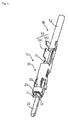
Figure 1 is a top view of an electrical terminal as a first embodiment of the present invention; -
Figure 2 is a right side view of the electrical terminal as the first embodiment of the present invention; -
Figure 3 is a cross-sectional view taken along arrow A-A shown inFigure 1 ; -
Figure 4 is an isometric view of the electrical terminal of the first embodiment; -
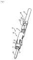
Figure 5 is an isometric view showing a contact identical to the contact shown inFigures 1 to 4 after crimping of a compensating lead wire; -
Figure 6 is an isometric view of an electrical terminal of a second embodiment of the present invention; and -
Figure 7 is an isometric view of a mating electrical terminal for mating with the electrical terminal of the second embodiment shown inFigure 6 . - Hereinafter, embodiments of the present invention will be described.
-
Figures 1 and 2 are a top view and a right side view, respectively, of an electrical terminal as a first embodiment of the present invention. - In addition,
Figure 3 is a cross-sectional view taken along arrow A-A shown inFigure 1 . - Further,
Figure 4 is an isometric view of the electrical terminal of the first embodiment. - In
Figures 1 to 4 , theelectrical terminal 10 is shown by way of example electrically connecting a thermocouple and a measuring device, not shown. - In
Figures 1 to 4 , in addition to theelectrical terminal 10, a compensatinglead wire 50 connected by crimping to theelectrical terminal 10 is also shown. Herein, though the compensatinglead wire 50 is placed in an attitude for being crimped to theelectrical terminal 10, theelectrical terminal 10 is shown in a pre-crimped state inFigures 1 to 4 . - Herein, a thermocouple, not shown, is a thermocouple using two kinds of metal wires made of alumel and chromel, as an example. The alumel wire and the chromel wire constituting the thermocouple are connected to an alumel compensating lead wire and a chromel compensating lead wire, respectively, via the
electrical terminal 10 having a structure shown herein, and led to a measuring device (not shown). - The
electrical terminal 10 has a contact or anelongate contact 20 and acoupling member 30. - The
contact 20 of theelectrical terminal 10 used for connection with the alumel wire of the thermocouple is a contact made of alumel metal. In addition, thecontact 20 of theelectrical terminal 10 used for connection with the chromel wire is a contact made of chromel metal. This is because interposition of a different kind of metal between the thermocouple and the measuring device causes a potential difference, which results in a factor in measurement error. However, alumel and chromel are both brittle, have poor spring property, and are unsuitable as electrical terminals as they are. Therefore, in the present embodiment, the electrical terminal has the following structure. - The
contact 20 of theelectrical terminal 10 has a shape extending frontward and rearward like a strip. However, thecontact 20 does not necessarily have to have a strip-like shape, but may have a shape extending like a rod. Herein, alumel or chromel that is a material for thecontact 20 corresponds to an example of a first kind of metal defined in the present invention. - In addition, the
contact 20 corresponds to an example of a first contact defined in the present invention. Thecontact 20 has aprojection 21 projecting only from one side face thereof. It is understood that when theprojection 21 is positioned on the left side when theelectrical terminal 10 shown is viewed from the front, thecontact 20 of theelectrical terminal 10 is one of alumel and chromel. In addition, it is understood that when theprojection 21 is positioned on the right side, thecontact 20 of theelectrical terminal 10 is the other of alumel and chromel. Theprojection 21 functions as a key preventing false insertion when theelectrical terminal 10 is inserted into a housing (not shown). - The
coupling member 30 is made of a copper alloy that is time-proven as an electrical terminal and suitable for an electrical terminal. Thecoupling member 30 is fixed to thecontact 20 by spot welding. Thecoupling member 30 has a substantially-rectangular sectional shape, and has at its front end aninsertion opening 31 through which a contact (not shown) of a mating electrical terminal is inserted. It should be noted that thecoupling member 30 may be fixed to thecontact 20 by swaging. - In addition, the
coupling member 30, as shown inFigures 3 and4 , has aspring portion 32. Thespring portion 32 is formed in a cantilever-like shape, a rear end thereof is a fixed end, and a front end thereof is a free end. Thespring portion 32 extends frontward and rearward along thecontact 20, and simultaneously the free end extends toward thecontact 20. - Herein, as a mating electrical terminal mating with the
electrical terminal 10, the same type (hermaphroditic) of electrical terminal as theelectrical terminal 10 can be adopted. However, when thecontact 20 of theelectrical terminal 10 is made of alumel, a mating electrical terminal mating with theelectrical terminal 10 is also an electrical terminal having a contact made of alumel. Similarly, when thecontact 20 of theelectrical terminal 10 is made of chromel, a contact of a mating electrical terminal is also made of chromel. - It should be noted that the alumel wire and the chromel wire constituting the thermocouple both have the same structures and the same dimensions as the compensating
lead wire 50 shown here. Therefore, hereinafter, the alumel wire and the chromel wire constituting the thermocouple and the compensatinglead wire 50 connecting the thermocouple and the measuring device may be both referred to as compensatinglead wire 50 without discrimination. - In mating the
electrical terminal 10 and the mating electrical terminal with each other, the mating electrical terminal is turned upside down unlike theelectrical terminal 10, and thecontact 20 of the mating electrical terminal is inserted through theinsertion opening 31 at the front end of thecoupling member 30 of theelectrical terminal 10. - Then, the contact of the mating electrical terminal is held between the
contact 20 of theelectrical terminal 10 and thespring portion 32 and pressed against thecontact 20, and thecontact 20 and the contact of the mating electrical terminal come into contact with each other with predetermined contact pressure. In addition, when an electrical terminal having the same shape as theelectrical terminal 10 is adopted as the mating electrical terminal, thecontact 20 of theelectrical terminal 10 is also pressed against the contact of the mating electrical terminal by the spring portion of the mating electrical terminal. In this manner, alumels or chromels, which are materials for thecontact 20, are connected together without interposition of a different metal material. Thecoupling member 30 including thespring portion 32 is made of a metal material having spring property suitable as a spring portion, such as a copper alloy, and can bring the contacts into contact with each other with predetermined contact pressure. Herein, a copper alloy or the like that is a material for thecoupling member 30 is an example of a second kind of metal defined in the present invention. - In addition, the
coupling member 30 of theelectrical terminal 10 has a crimpingportion 33 crimping and fixing the compensatinglead wire 50. The compensatinglead wire 50 shown here is composed of acore 51 and asheath 52 covering thecore 51. Thecore 51 is made of alumel or chromel. The compensatinglead wire 50 having thealumel core 51 is crimped and fixed to theelectrical terminal 10 having thealumel contact 20. Similarly, the compensatinglead wire 50 having thechromel core 51 is crimped and fixed to theelectrical terminal 10 having thechromel contact 20. - The crimping
portion 33 of thecoupling member 30 of theelectrical terminal 10 has acore crimping portion 331 crimping the core 51 stripped. Thecore crimping portion 331 has an open-top substantially U-sectional shape. For crimping the compensatinglead wire 50 to theelectrical terminal 10, thecore 51 is stripped or exposed by removing thesheath 52 at a distal end portion of the compensatinglead wire 50. Then, the strippedcore 51 is disposed in thecore crimping portion 331. A rear end portion of thecontact 20 extends to thecore crimping portion 331. For this reason, when being disposed in thecore crimping portion 331, the core 51 lies on thecontact 20, and comes into direct contact with thecontact 20. - In addition, the crimping
portion 33 of thecoupling member 30 of theelectrical terminal 10 has asheath crimping portion 332 behind thecore crimping portion 331. Thesheath crimping portion 332 plays a role in crimping a portion of the compensatinglead wire 50 where thecore 51 is covered with thesheath 52, the portion being located at a slight distance rearward from the distal end portion having the strippedcore 51. Thesheath crimping portion 332 also has a substantially U-sectional shape, and has an open-top shape, as in the case of thecore crimping portion 331. Then, the strippedcore 51 at the stripped distal end portion of the compensatinglead wire 50 is placed in thecore crimping portion 331, and simultaneously the portion therebehind where thecore 51 is covered with thesheath 52 is placed in thesheath crimping portion 332. Herein, a rear end portion of thecontact 20 extends to thecore crimping portion 331 but not to thesheath crimping portion 332. For this reason, as shown inFigure 3 , in thecore crimping portion 331, thecore 51 is placed in a higher position than a lower face of thesheath 52 in thesheath crimping portion 332 by the thickness of thecontact 20 including thesheath 52. The thickness of thecontact 20 is adjusted so that thecore 51 is located at a center of a cross-section of the compensatinglead wire 50 even after crimping. - The compensating
lead wire 50 has the core 51 stripped at the distal end portion, and is disposed in the crimpingportion 33 of thecontact 20 in a state shown inFigure 3 , and crimped. - The
coupling member 30 has alatch 34 catching on a catchingportion 22 of thecontact 20, thereby preventing thecontact 20 from coming off frontward. In addition, thecontact 20 has acontact point 23 that is so embossed from the bottom face side as to project upward. -
Figure 5 is an isometric view showing a contact identical to the contact shown inFigures 1 to 4 after crimping of the compensating lead wire. - When
Figure 5 is compared withFigure 4 showing the isometric view before crimping, the respective open-top portions of thecore crimping portion 331 and thesheath crimping portion 332 of the crimpingportion 33, which were formed in a substantially U-shape and had an open-top shape before crimping, are bent. Thereby, in thecore crimping portion 331, thecore 51 of the compensatinglead wire 50 is directly pressed against and electrically connected to thecontact 20 of theelectrical terminal 10. In addition, in thesheath crimping portion 332, the compensatinglead wire 50 is firmly fixed to theelectrical terminal 10. Even if unintentional force is applied to the compensatinglead wire 50 in the crimped state, the force is not transmitted to the core 51 in thecore crimping portion 331 since the compensatinglead wire 50 is crimped and fixed in thesheath crimping portion 332. For this reason, in thecore crimping portion 331, connection between the core 51 and thecontact 20 is stably maintained. - The material for the core 51, which is alumel, chromel, or the like, is brittle and not a material having resistance to bending or the like for crimping. In the case of the present embodiment, the
coupling member 30 made of a material suitable for crimping, such as a copper alloy, is fixed to thecontact 20 made of alumel, chromel, or the like, and thecoupling member 30 is provided with the crimpingportion 33. For this reason, according to theelectrical terminal 10 of the present embodiment, even a core made of a brittle material, such as alumel or chromel, can be reliably crimped and fixed. - In this manner, when the
electrical terminal 10 is adopted, and the same type of electrical terminal as the electrical terminal is also adopted as a mating electrical terminal, an alumel wire or a chromel wire of a thermocouple can be extended to a measuring device via the electrical terminal using an electrical wire made of the same material without interposition of a different metal. -
Figure 6 is an isometric view of an electrical terminal of a second embodiment of the present invention. Herein, inFigure 6 , a shape after the compensatinglead wire 50 is crimped is shown. - In the case of the
electrical terminal 10 of the first embodiment shown inFigures 1 to 5 , thecontact 20 projects further frontward beyond theinsertion opening 31 in the front end of thecoupling member 30. In contrast, in the case of an electrical terminal 10' of the second embodiment shown inFigure 6 , a contact 20' thereof extends only to the same position as the front end of thecoupling member 30. The electrical terminal 10' of the second embodiment is different only in the contact 20' from theelectrical terminal 10 of the first embodiment. Therefore, inFigure 6 , the same components as theelectrical terminal 10 of the first embodiment are denoted with the same reference signs as those attached inFigures 1 to 5 so that the structure of the electrical terminal 10' will not be described anymore. - In the case of the electrical terminal 10' of the second embodiment shown in
Figure 6 , a contact having a shape inserted into a mating electrical terminal is not provided. The electrical terminal 10' receives insertion of a male contact of a mating electrical terminal (for example, thecontact 20 of theelectrical terminal 10 shown inFigures 1 to 5 ). Then, the contact of the mating electrical terminal is pressed against the contact 20' of the electrical terminal 10' by the spring portion 32 (seeFigure 3 together) of the electrical terminal 10', and the contacts are thus connected together. -
Figure 7 is an isometric view of a mating electrical terminal mating with the electrical terminal of the second embodiment shown inFigure 6 . - The mating
electrical terminal 10" shown inFigure 7 , as compared with theelectrical terminal 10 of the first embodiment shown inFigures 1 to 5 , has a shape obtained by removing thespring portion 32 from thecoupling member 30 of theelectrical terminal 10 of the first embodiment. Components other than thespring portion 32 of the matingelectrical terminal 10" are the same as those of theelectrical terminal 10 of the first embodiment, and the same components are denoted with the same reference signs so that the structure of theelectrical terminal 10" will not be described anymore. - In the electrical terminal 10' of the second embodiment shown in
Figure 6 , a type of contact that is inserted into a mating electrical terminal is not present. Therefore, the matingelectrical terminal 10" is not provided with a structure corresponding to the spring portion 32 (seeFigure 3 ) of theelectrical terminal 10 of the first embodiment shown inFigures 1 to 5 . However, the matingelectrical terminal 10" also needs a structure that crimps the compensatinglead wire 50, as shown inFigure 7 . - In the case of the
electrical terminal 10 of the first embodiment shown inFigures 1 to 5 , the same type of electrical terminal can be so adopted as a mating electrical terminal. Therefore, parts control for the electrical terminal is facilitated. However, as electrical terminals for a thermocouple, non-hermaphroditic electrical terminals are conventionally used. Therefore, in the case of following the practice, a combination of the electrical terminal 10' shown inFigure 6 and the matingelectrical terminal 10" shown inFigure 7 , for example, can be adopted. - It should be noted that, herein, using alumel or chromel as the
contacts 20, 20' has been described by way of example. However, metal materials constituting a thermocouple are not limited to alumel and chromel. A different metal material may be used for a thermocouple. That is, as a thermocouple material, in addition to alumel or chromel, for example, constantan, nicrosil, nisil, iron, platinum, platinum-rhodium alloy, iridium, iridium-rhodium alloy, tungsten-rhenium alloy, nichrome, gold-iron alloy, nickel, nickel-molybdenum alloy, palladium-platinum-gold alloy, gold-palladium alloy, gold-cobalt alloy, or the like may be used. Therefore, as a contact of the electrical terminal of the present invention, a different metal material may also be used accordingly. - In addition, herein, though an electrical terminal for a thermocouple has been described by way of example, a scope of application of the present invention is not limited to a thermocouple. For example, pure copper may be adopted in order to flow large current. The pure copper is so soft that it is difficult for the pure copper to constitute an electrical terminal by itself. Therefore, an electrical terminal having the structure shown in
Figures 1 to 5 orFigure 6 may be produced by adapting a contact made of pure copper. - In this manner, the present invention is widely applicable when electrical signal transmission or power transmission is required to be performed using a metal material having a difficulty in constituting an electrical terminal by itself.
-
- 10, 10'
- Electrical terminal
- 10"
- Mating electrical terminal
- 20, 20'
- Contact
- 30
- Coupling member
- 31
- Insertion opening
- 32
- Spring portion
- 33
- Crimping portion
- 50
- Compensating lead wire
- 51
- Core
- 52
- Sheath
- 331
- Core crimping portion
- 332
- Sheath crimping portion
Claims (5)
- An electrical terminal (10) comprising:an elongate first contact (20) made of a first kind of metal; anda coupling member (30) having a spring portion (32) formed in a cantilever-like shape, extending along the first contact (20) and having a free end extending toward the first contact (20), and configured to hold a second contact of a mating electrical terminal made of the same kind of metal as the first contact (20) between the spring portion (32) and the first contact (20) and press the second contact against the first contact (20), wherein the coupling member (30) is made of a second kind of metal different from the first kind, and the coupling member (30) is fixed to the first contact (20).
- The electrical terminal according to claim 1, wherein
the coupling member (30) further has a crimping portion (331) configured to be crimped in such a state that an electrical wire (50) made of the same kind of metal as the first contact (20) is pressed against the first contact (20), and wherein
the coupling member (30) is fixed to the first contact (20) independently of crimping at the crimping portion. - The electrical terminal according to claim 2, wherein the crimping portion (33) has a core crimping portion (331) for pressing an exposed portion of a core (51) of the electrical wire (50) against the first contact (20).
- The electrical terminal according to claim 2 or 3, wherein the crimping portion (33) has a sheath crimping portion (332) for being crimped to a sheath (52) of the electrical wire (50).
- The electrical terminal according to any preceding claim, wherein the first contact (20) extends like a rod or strip.
Applications Claiming Priority (1)
| Application Number | Priority Date | Filing Date | Title |
|---|---|---|---|
| JP2015154091A JP6532160B2 (en) | 2015-08-04 | 2015-08-04 | Electrical terminal |
Publications (2)
| Publication Number | Publication Date |
|---|---|
| EP3128614A1 true EP3128614A1 (en) | 2017-02-08 |
| EP3128614B1 EP3128614B1 (en) | 2019-09-25 |
Family
ID=56561273
Family Applications (1)
| Application Number | Title | Priority Date | Filing Date |
|---|---|---|---|
| EP16182270.5A Active EP3128614B1 (en) | 2015-08-04 | 2016-08-01 | Electrical terminal structure |
Country Status (6)
| Country | Link |
|---|---|
| US (1) | US9812802B2 (en) |
| EP (1) | EP3128614B1 (en) |
| JP (1) | JP6532160B2 (en) |
| KR (1) | KR102748940B1 (en) |
| CN (1) | CN106450858B (en) |
| TW (1) | TWI680612B (en) |
Cited By (1)
| Publication number | Priority date | Publication date | Assignee | Title |
|---|---|---|---|---|
| EP4311036A3 (en) * | 2019-08-29 | 2024-05-01 | J.S.T. Corporation | An electrical male terminal, and methods for connecting thereof |
Families Citing this family (4)
| Publication number | Priority date | Publication date | Assignee | Title |
|---|---|---|---|---|
| JP6361477B2 (en) * | 2014-11-19 | 2018-07-25 | 株式会社オートネットワーク技術研究所 | Connector terminal |
| JP6666211B2 (en) * | 2016-07-19 | 2020-03-13 | タイコエレクトロニクスジャパン合同会社 | contact |
| JP2024515903A (en) * | 2021-06-21 | 2024-04-11 | ジェイ.エス.ティー.コーポレーション | Electrical Male Terminal |
| CN115968521A (en) * | 2021-06-21 | 2023-04-14 | J.S.T.公司 | Electrical male terminal |
Citations (4)
| Publication number | Priority date | Publication date | Assignee | Title |
|---|---|---|---|---|
| JPH056720U (en) | 1991-07-10 | 1993-01-29 | 日本電気株式会社 | Structure of thermocouple connector |
| JP2002026399A (en) | 2000-07-07 | 2002-01-25 | Aisin Seiki Co Ltd | Thermocouple connector |
| US7556541B2 (en) * | 2006-10-06 | 2009-07-07 | Fci Americas Technology, Inc. | Electrical terminal with high conductivity core |
| WO2013161551A1 (en) * | 2012-04-23 | 2013-10-31 | 株式会社オートネットワーク技術研究所 | Terminal and electrical wire with terminal |
Family Cites Families (21)
| Publication number | Priority date | Publication date | Assignee | Title |
|---|---|---|---|---|
| JPS5337085A (en) * | 1976-09-17 | 1978-04-05 | Hitachi Ltd | Thermocouple connector |
| JPH071742Y2 (en) * | 1989-11-30 | 1995-01-18 | 安立計器株式会社 | Measuring instrument connector |
| KR930006720A (en) | 1991-09-26 | 1993-04-21 | 성백은 | Subway information system using LDP (LASER DISK PLAYER) |
| JPH071578U (en) | 1992-04-16 | 1995-01-10 | 株式会社岡崎製作所 | Thermocouple connector |
| US5593328A (en) * | 1993-11-04 | 1997-01-14 | Sumitomo Wiring Systems, Ltd. | Female terminal fitting for connector |
| JP3000834U (en) | 1994-02-08 | 1994-08-16 | 株式会社岡崎製作所 | Thermocouple connector |
| JPH0996570A (en) * | 1995-09-29 | 1997-04-08 | Nec Corp | Thermocouple connector |
| EP1006613B1 (en) * | 1998-12-01 | 2003-08-06 | Thomas & Betts International, Inc. | Improved two piece male pin terminal connector |
| KR100360911B1 (en) | 2000-10-02 | 2002-11-22 | 현대자동차주식회사 | Exhaust noise reduction apparatus |
| JP3749670B2 (en) * | 2001-03-13 | 2006-03-01 | 住友電装株式会社 | Combination terminal fitting and assembly structure of multiple terminal fittings |
| JP4476916B2 (en) * | 2005-11-28 | 2010-06-09 | 春日電機株式会社 | Thermocouple terminal block |
| CN101453072A (en) * | 2007-05-08 | 2009-06-10 | 泰科电子公司 | Electrical contact |
| JP2009283308A (en) * | 2008-05-22 | 2009-12-03 | Yazaki Corp | Female terminal |
| EP2151894A1 (en) * | 2008-08-08 | 2010-02-10 | Sumitomo Wiring Systems, Ltd. | A terminal fitting, a wire connected with a terminal fitting and a connecting method therefor |
| GB0815210D0 (en) * | 2008-08-21 | 2008-09-24 | Rolls Royce Plc | Thermocouple connector |
| JP5755506B2 (en) * | 2011-06-02 | 2015-07-29 | 矢崎総業株式会社 | Terminal fitting |
| JP2013149564A (en) * | 2012-01-23 | 2013-08-01 | Auto Network Gijutsu Kenkyusho:Kk | Terminal fitting |
| JP5772643B2 (en) * | 2012-02-10 | 2015-09-02 | 株式会社オートネットワーク技術研究所 | Terminal fitting |
| TWM443297U (en) * | 2012-06-29 | 2012-12-11 | Cvilux Corp | Terminal assembly |
| JP6063788B2 (en) * | 2013-03-19 | 2017-01-18 | 矢崎総業株式会社 | Manufacturing method of terminal fitting and electric wire with terminal |
| JP6563272B2 (en) * | 2015-08-04 | 2019-08-21 | タイコエレクトロニクスジャパン合同会社 | Electrical terminal |
-
2015
- 2015-08-04 JP JP2015154091A patent/JP6532160B2/en active Active
-
2016
- 2016-07-06 TW TW105121350A patent/TWI680612B/en active
- 2016-07-26 KR KR1020160095031A patent/KR102748940B1/en active Active
- 2016-07-29 CN CN201610609644.XA patent/CN106450858B/en active Active
- 2016-08-01 EP EP16182270.5A patent/EP3128614B1/en active Active
- 2016-08-02 US US15/225,930 patent/US9812802B2/en active Active
Patent Citations (4)
| Publication number | Priority date | Publication date | Assignee | Title |
|---|---|---|---|---|
| JPH056720U (en) | 1991-07-10 | 1993-01-29 | 日本電気株式会社 | Structure of thermocouple connector |
| JP2002026399A (en) | 2000-07-07 | 2002-01-25 | Aisin Seiki Co Ltd | Thermocouple connector |
| US7556541B2 (en) * | 2006-10-06 | 2009-07-07 | Fci Americas Technology, Inc. | Electrical terminal with high conductivity core |
| WO2013161551A1 (en) * | 2012-04-23 | 2013-10-31 | 株式会社オートネットワーク技術研究所 | Terminal and electrical wire with terminal |
Cited By (1)
| Publication number | Priority date | Publication date | Assignee | Title |
|---|---|---|---|---|
| EP4311036A3 (en) * | 2019-08-29 | 2024-05-01 | J.S.T. Corporation | An electrical male terminal, and methods for connecting thereof |
Also Published As
| Publication number | Publication date |
|---|---|
| KR20170016786A (en) | 2017-02-14 |
| JP2017033828A (en) | 2017-02-09 |
| US20170040727A1 (en) | 2017-02-09 |
| CN106450858A (en) | 2017-02-22 |
| JP6532160B2 (en) | 2019-06-19 |
| EP3128614B1 (en) | 2019-09-25 |
| TWI680612B (en) | 2019-12-21 |
| US9812802B2 (en) | 2017-11-07 |
| KR102748940B1 (en) | 2025-01-02 |
| TW201707288A (en) | 2017-02-16 |
| CN106450858B (en) | 2019-09-03 |
Similar Documents
| Publication | Publication Date | Title |
|---|---|---|
| EP3128614B1 (en) | Electrical terminal structure | |
| US3721943A (en) | Electrical connecting device | |
| US20120322307A1 (en) | Shield connector | |
| US20150349448A1 (en) | Connector | |
| JP4440160B2 (en) | connector | |
| CN111194512B (en) | wire holding part | |
| US10317290B2 (en) | Contact | |
| US10756478B2 (en) | Terminal and method of connecting electric wire to terminal | |
| EP3128613B1 (en) | Electrical terminal | |
| JP5798840B2 (en) | Connecting terminal | |
| JP3794608B2 (en) | Connector continuity test tool | |
| US5171166A (en) | Miniature electrical contact terminal | |
| JP4476916B2 (en) | Thermocouple terminal block | |
| US7985104B2 (en) | Shield sleeve for a plug connector | |
| JP6330845B2 (en) | Wire connector | |
| JPH0757792A (en) | Pressure-connection type connector | |
| JP2019061795A (en) | Power supply connector | |
| CN108232477B (en) | Connector free of welding and wire stripping | |
| JP2008166136A (en) | Connection member and harness connection body using the member | |
| JP2015225714A (en) | connector | |
| JP2003203705A (en) | Electrical connection structure using fork-shaped terminals and electrical components | |
| JP2015201333A (en) | Connector terminal | |
| JPH11204227A (en) | Connector |
Legal Events
| Date | Code | Title | Description |
|---|---|---|---|
| PUAI | Public reference made under article 153(3) epc to a published international application that has entered the european phase |
Free format text: ORIGINAL CODE: 0009012 |
|
| STAA | Information on the status of an ep patent application or granted ep patent |
Free format text: STATUS: THE APPLICATION HAS BEEN PUBLISHED |
|
| AK | Designated contracting states |
Kind code of ref document: A1 Designated state(s): AL AT BE BG CH CY CZ DE DK EE ES FI FR GB GR HR HU IE IS IT LI LT LU LV MC MK MT NL NO PL PT RO RS SE SI SK SM TR |
|
| AX | Request for extension of the european patent |
Extension state: BA ME |
|
| STAA | Information on the status of an ep patent application or granted ep patent |
Free format text: STATUS: REQUEST FOR EXAMINATION WAS MADE |
|
| 17P | Request for examination filed |
Effective date: 20170802 |
|
| RBV | Designated contracting states (corrected) |
Designated state(s): AL AT BE BG CH CY CZ DE DK EE ES FI FR GB GR HR HU IE IS IT LI LT LU LV MC MK MT NL NO PL PT RO RS SE SI SK SM TR |
|
| STAA | Information on the status of an ep patent application or granted ep patent |
Free format text: STATUS: EXAMINATION IS IN PROGRESS |
|
| 17Q | First examination report despatched |
Effective date: 20180419 |
|
| REG | Reference to a national code |
Ref country code: DE Ref legal event code: R079 Ref document number: 602016021131 Country of ref document: DE Free format text: PREVIOUS MAIN CLASS: H01R0004180000 Ipc: H01R0004020000 |
|
| GRAP | Despatch of communication of intention to grant a patent |
Free format text: ORIGINAL CODE: EPIDOSNIGR1 |
|
| STAA | Information on the status of an ep patent application or granted ep patent |
Free format text: STATUS: GRANT OF PATENT IS INTENDED |
|
| RIC1 | Information provided on ipc code assigned before grant |
Ipc: H01R 13/05 20060101ALI20190308BHEP Ipc: H01R 4/18 20060101ALI20190308BHEP Ipc: H01R 4/02 20060101AFI20190308BHEP Ipc: H01R 13/03 20060101ALI20190308BHEP Ipc: H01R 13/11 20060101ALI20190308BHEP Ipc: H01R 24/20 20110101ALI20190308BHEP Ipc: H01R 24/28 20110101ALI20190308BHEP Ipc: H01R 101/00 20060101ALI20190308BHEP Ipc: H01R 4/62 20060101ALI20190308BHEP |
|
| INTG | Intention to grant announced |
Effective date: 20190412 |
|
| GRAS | Grant fee paid |
Free format text: ORIGINAL CODE: EPIDOSNIGR3 |
|
| GRAA | (expected) grant |
Free format text: ORIGINAL CODE: 0009210 |
|
| STAA | Information on the status of an ep patent application or granted ep patent |
Free format text: STATUS: THE PATENT HAS BEEN GRANTED |
|
| AK | Designated contracting states |
Kind code of ref document: B1 Designated state(s): AL AT BE BG CH CY CZ DE DK EE ES FI FR GB GR HR HU IE IS IT LI LT LU LV MC MK MT NL NO PL PT RO RS SE SI SK SM TR |
|
| REG | Reference to a national code |
Ref country code: GB Ref legal event code: FG4D |
|
| REG | Reference to a national code |
Ref country code: CH Ref legal event code: EP |
|
| REG | Reference to a national code |
Ref country code: AT Ref legal event code: REF Ref document number: 1184739 Country of ref document: AT Kind code of ref document: T Effective date: 20191015 |
|
| REG | Reference to a national code |
Ref country code: IE Ref legal event code: FG4D |
|
| REG | Reference to a national code |
Ref country code: DE Ref legal event code: R096 Ref document number: 602016021131 Country of ref document: DE |
|
| REG | Reference to a national code |
Ref country code: NL Ref legal event code: FP |
|
| PG25 | Lapsed in a contracting state [announced via postgrant information from national office to epo] |
Ref country code: SE Free format text: LAPSE BECAUSE OF FAILURE TO SUBMIT A TRANSLATION OF THE DESCRIPTION OR TO PAY THE FEE WITHIN THE PRESCRIBED TIME-LIMIT Effective date: 20190925 Ref country code: HR Free format text: LAPSE BECAUSE OF FAILURE TO SUBMIT A TRANSLATION OF THE DESCRIPTION OR TO PAY THE FEE WITHIN THE PRESCRIBED TIME-LIMIT Effective date: 20190925 Ref country code: FI Free format text: LAPSE BECAUSE OF FAILURE TO SUBMIT A TRANSLATION OF THE DESCRIPTION OR TO PAY THE FEE WITHIN THE PRESCRIBED TIME-LIMIT Effective date: 20190925 Ref country code: LT Free format text: LAPSE BECAUSE OF FAILURE TO SUBMIT A TRANSLATION OF THE DESCRIPTION OR TO PAY THE FEE WITHIN THE PRESCRIBED TIME-LIMIT Effective date: 20190925 Ref country code: BG Free format text: LAPSE BECAUSE OF FAILURE TO SUBMIT A TRANSLATION OF THE DESCRIPTION OR TO PAY THE FEE WITHIN THE PRESCRIBED TIME-LIMIT Effective date: 20191225 Ref country code: NO Free format text: LAPSE BECAUSE OF FAILURE TO SUBMIT A TRANSLATION OF THE DESCRIPTION OR TO PAY THE FEE WITHIN THE PRESCRIBED TIME-LIMIT Effective date: 20191225 |
|
| REG | Reference to a national code |
Ref country code: LT Ref legal event code: MG4D |
|
| PG25 | Lapsed in a contracting state [announced via postgrant information from national office to epo] |
Ref country code: LV Free format text: LAPSE BECAUSE OF FAILURE TO SUBMIT A TRANSLATION OF THE DESCRIPTION OR TO PAY THE FEE WITHIN THE PRESCRIBED TIME-LIMIT Effective date: 20190925 Ref country code: GR Free format text: LAPSE BECAUSE OF FAILURE TO SUBMIT A TRANSLATION OF THE DESCRIPTION OR TO PAY THE FEE WITHIN THE PRESCRIBED TIME-LIMIT Effective date: 20191226 Ref country code: RS Free format text: LAPSE BECAUSE OF FAILURE TO SUBMIT A TRANSLATION OF THE DESCRIPTION OR TO PAY THE FEE WITHIN THE PRESCRIBED TIME-LIMIT Effective date: 20190925 |
|
| REG | Reference to a national code |
Ref country code: AT Ref legal event code: MK05 Ref document number: 1184739 Country of ref document: AT Kind code of ref document: T Effective date: 20190925 |
|
| PG25 | Lapsed in a contracting state [announced via postgrant information from national office to epo] |
Ref country code: PT Free format text: LAPSE BECAUSE OF FAILURE TO SUBMIT A TRANSLATION OF THE DESCRIPTION OR TO PAY THE FEE WITHIN THE PRESCRIBED TIME-LIMIT Effective date: 20200127 Ref country code: IT Free format text: LAPSE BECAUSE OF FAILURE TO SUBMIT A TRANSLATION OF THE DESCRIPTION OR TO PAY THE FEE WITHIN THE PRESCRIBED TIME-LIMIT Effective date: 20190925 Ref country code: ES Free format text: LAPSE BECAUSE OF FAILURE TO SUBMIT A TRANSLATION OF THE DESCRIPTION OR TO PAY THE FEE WITHIN THE PRESCRIBED TIME-LIMIT Effective date: 20190925 Ref country code: RO Free format text: LAPSE BECAUSE OF FAILURE TO SUBMIT A TRANSLATION OF THE DESCRIPTION OR TO PAY THE FEE WITHIN THE PRESCRIBED TIME-LIMIT Effective date: 20190925 Ref country code: EE Free format text: LAPSE BECAUSE OF FAILURE TO SUBMIT A TRANSLATION OF THE DESCRIPTION OR TO PAY THE FEE WITHIN THE PRESCRIBED TIME-LIMIT Effective date: 20190925 Ref country code: AT Free format text: LAPSE BECAUSE OF FAILURE TO SUBMIT A TRANSLATION OF THE DESCRIPTION OR TO PAY THE FEE WITHIN THE PRESCRIBED TIME-LIMIT Effective date: 20190925 Ref country code: PL Free format text: LAPSE BECAUSE OF FAILURE TO SUBMIT A TRANSLATION OF THE DESCRIPTION OR TO PAY THE FEE WITHIN THE PRESCRIBED TIME-LIMIT Effective date: 20190925 Ref country code: AL Free format text: LAPSE BECAUSE OF FAILURE TO SUBMIT A TRANSLATION OF THE DESCRIPTION OR TO PAY THE FEE WITHIN THE PRESCRIBED TIME-LIMIT Effective date: 20190925 |
|
| PG25 | Lapsed in a contracting state [announced via postgrant information from national office to epo] |
Ref country code: IS Free format text: LAPSE BECAUSE OF FAILURE TO SUBMIT A TRANSLATION OF THE DESCRIPTION OR TO PAY THE FEE WITHIN THE PRESCRIBED TIME-LIMIT Effective date: 20200224 Ref country code: SM Free format text: LAPSE BECAUSE OF FAILURE TO SUBMIT A TRANSLATION OF THE DESCRIPTION OR TO PAY THE FEE WITHIN THE PRESCRIBED TIME-LIMIT Effective date: 20190925 Ref country code: SK Free format text: LAPSE BECAUSE OF FAILURE TO SUBMIT A TRANSLATION OF THE DESCRIPTION OR TO PAY THE FEE WITHIN THE PRESCRIBED TIME-LIMIT Effective date: 20190925 Ref country code: CZ Free format text: LAPSE BECAUSE OF FAILURE TO SUBMIT A TRANSLATION OF THE DESCRIPTION OR TO PAY THE FEE WITHIN THE PRESCRIBED TIME-LIMIT Effective date: 20190925 |
|
| REG | Reference to a national code |
Ref country code: DE Ref legal event code: R097 Ref document number: 602016021131 Country of ref document: DE |
|
| PG2D | Information on lapse in contracting state deleted |
Ref country code: IS |
|
| PG25 | Lapsed in a contracting state [announced via postgrant information from national office to epo] |
Ref country code: DK Free format text: LAPSE BECAUSE OF FAILURE TO SUBMIT A TRANSLATION OF THE DESCRIPTION OR TO PAY THE FEE WITHIN THE PRESCRIBED TIME-LIMIT Effective date: 20190925 Ref country code: IS Free format text: LAPSE BECAUSE OF FAILURE TO SUBMIT A TRANSLATION OF THE DESCRIPTION OR TO PAY THE FEE WITHIN THE PRESCRIBED TIME-LIMIT Effective date: 20200126 |
|
| PLBE | No opposition filed within time limit |
Free format text: ORIGINAL CODE: 0009261 |
|
| STAA | Information on the status of an ep patent application or granted ep patent |
Free format text: STATUS: NO OPPOSITION FILED WITHIN TIME LIMIT |
|
| 26N | No opposition filed |
Effective date: 20200626 |
|
| PG25 | Lapsed in a contracting state [announced via postgrant information from national office to epo] |
Ref country code: SI Free format text: LAPSE BECAUSE OF FAILURE TO SUBMIT A TRANSLATION OF THE DESCRIPTION OR TO PAY THE FEE WITHIN THE PRESCRIBED TIME-LIMIT Effective date: 20190925 |
|
| PG25 | Lapsed in a contracting state [announced via postgrant information from national office to epo] |
Ref country code: MC Free format text: LAPSE BECAUSE OF FAILURE TO SUBMIT A TRANSLATION OF THE DESCRIPTION OR TO PAY THE FEE WITHIN THE PRESCRIBED TIME-LIMIT Effective date: 20190925 |
|
| REG | Reference to a national code |
Ref country code: CH Ref legal event code: PL |
|
| GBPC | Gb: european patent ceased through non-payment of renewal fee |
Effective date: 20200801 |
|
| PG25 | Lapsed in a contracting state [announced via postgrant information from national office to epo] |
Ref country code: CH Free format text: LAPSE BECAUSE OF NON-PAYMENT OF DUE FEES Effective date: 20200831 Ref country code: LU Free format text: LAPSE BECAUSE OF NON-PAYMENT OF DUE FEES Effective date: 20200801 Ref country code: LI Free format text: LAPSE BECAUSE OF NON-PAYMENT OF DUE FEES Effective date: 20200831 |
|
| REG | Reference to a national code |
Ref country code: BE Ref legal event code: MM Effective date: 20200831 |
|
| PG25 | Lapsed in a contracting state [announced via postgrant information from national office to epo] |
Ref country code: FR Free format text: LAPSE BECAUSE OF NON-PAYMENT OF DUE FEES Effective date: 20200831 |
|
| PG25 | Lapsed in a contracting state [announced via postgrant information from national office to epo] |
Ref country code: IE Free format text: LAPSE BECAUSE OF NON-PAYMENT OF DUE FEES Effective date: 20200801 Ref country code: GB Free format text: LAPSE BECAUSE OF NON-PAYMENT OF DUE FEES Effective date: 20200801 Ref country code: BE Free format text: LAPSE BECAUSE OF NON-PAYMENT OF DUE FEES Effective date: 20200831 |
|
| PG25 | Lapsed in a contracting state [announced via postgrant information from national office to epo] |
Ref country code: TR Free format text: LAPSE BECAUSE OF FAILURE TO SUBMIT A TRANSLATION OF THE DESCRIPTION OR TO PAY THE FEE WITHIN THE PRESCRIBED TIME-LIMIT Effective date: 20190925 Ref country code: MT Free format text: LAPSE BECAUSE OF FAILURE TO SUBMIT A TRANSLATION OF THE DESCRIPTION OR TO PAY THE FEE WITHIN THE PRESCRIBED TIME-LIMIT Effective date: 20190925 Ref country code: CY Free format text: LAPSE BECAUSE OF FAILURE TO SUBMIT A TRANSLATION OF THE DESCRIPTION OR TO PAY THE FEE WITHIN THE PRESCRIBED TIME-LIMIT Effective date: 20190925 |
|
| PG25 | Lapsed in a contracting state [announced via postgrant information from national office to epo] |
Ref country code: MK Free format text: LAPSE BECAUSE OF FAILURE TO SUBMIT A TRANSLATION OF THE DESCRIPTION OR TO PAY THE FEE WITHIN THE PRESCRIBED TIME-LIMIT Effective date: 20190925 |
|
| PGFP | Annual fee paid to national office [announced via postgrant information from national office to epo] |
Ref country code: NL Payment date: 20250613 Year of fee payment: 10 |
|
| PGFP | Annual fee paid to national office [announced via postgrant information from national office to epo] |
Ref country code: DE Payment date: 20250604 Year of fee payment: 10 |