EP3128290B1 - Methods and system for determining shear angle - Google Patents
Methods and system for determining shear angle Download PDFInfo
- Publication number
- EP3128290B1 EP3128290B1 EP16172864.7A EP16172864A EP3128290B1 EP 3128290 B1 EP3128290 B1 EP 3128290B1 EP 16172864 A EP16172864 A EP 16172864A EP 3128290 B1 EP3128290 B1 EP 3128290B1
- Authority
- EP
- European Patent Office
- Prior art keywords
- shear angle
- angle
- facesheet
- radiation source
- cellular panel
- Prior art date
- Legal status (The legal status is an assumption and is not a legal conclusion. Google has not performed a legal analysis and makes no representation as to the accuracy of the status listed.)
- Active
Links
- NYDDQEGRUKPQFQ-BPNZPQAUSA-N C[C@]1(CC2)[C@@](C)(CC3)CC3CC2C1 Chemical compound C[C@]1(CC2)[C@@](C)(CC3)CC3CC2C1 NYDDQEGRUKPQFQ-BPNZPQAUSA-N 0.000 description 1
Images






Classifications
-
- G—PHYSICS
- G01—MEASURING; TESTING
- G01N—INVESTIGATING OR ANALYSING MATERIALS BY DETERMINING THEIR CHEMICAL OR PHYSICAL PROPERTIES
- G01N23/00—Investigating or analysing materials by the use of wave or particle radiation, e.g. X-rays or neutrons, not covered by groups G01N3/00 – G01N17/00, G01N21/00 or G01N22/00
- G01N23/02—Investigating or analysing materials by the use of wave or particle radiation, e.g. X-rays or neutrons, not covered by groups G01N3/00 – G01N17/00, G01N21/00 or G01N22/00 by transmitting the radiation through the material
- G01N23/04—Investigating or analysing materials by the use of wave or particle radiation, e.g. X-rays or neutrons, not covered by groups G01N3/00 – G01N17/00, G01N21/00 or G01N22/00 by transmitting the radiation through the material and forming images of the material
-
- G—PHYSICS
- G01—MEASURING; TESTING
- G01B—MEASURING LENGTH, THICKNESS OR SIMILAR LINEAR DIMENSIONS; MEASURING ANGLES; MEASURING AREAS; MEASURING IRREGULARITIES OF SURFACES OR CONTOURS
- G01B15/00—Measuring arrangements characterised by the use of electromagnetic waves or particle radiation, e.g. by the use of microwaves, X-rays, gamma rays or electrons
-
- B—PERFORMING OPERATIONS; TRANSPORTING
- B32—LAYERED PRODUCTS
- B32B—LAYERED PRODUCTS, i.e. PRODUCTS BUILT-UP OF STRATA OF FLAT OR NON-FLAT, e.g. CELLULAR OR HONEYCOMB, FORM
- B32B3/00—Layered products comprising a layer with external or internal discontinuities or unevennesses, or a layer of non-planar shape; Layered products comprising a layer having particular features of form
-
- G—PHYSICS
- G01—MEASURING; TESTING
- G01N—INVESTIGATING OR ANALYSING MATERIALS BY DETERMINING THEIR CHEMICAL OR PHYSICAL PROPERTIES
- G01N1/00—Sampling; Preparing specimens for investigation
-
- G—PHYSICS
- G01—MEASURING; TESTING
- G01N—INVESTIGATING OR ANALYSING MATERIALS BY DETERMINING THEIR CHEMICAL OR PHYSICAL PROPERTIES
- G01N2223/00—Investigating materials by wave or particle radiation
- G01N2223/30—Accessories, mechanical or electrical features
- G01N2223/33—Accessories, mechanical or electrical features scanning, i.e. relative motion for measurement of successive object-parts
-
- G—PHYSICS
- G01—MEASURING; TESTING
- G01N—INVESTIGATING OR ANALYSING MATERIALS BY DETERMINING THEIR CHEMICAL OR PHYSICAL PROPERTIES
- G01N2223/00—Investigating materials by wave or particle radiation
- G01N2223/60—Specific applications or type of materials
- G01N2223/615—Specific applications or type of materials composite materials, multilayer laminates
Definitions
- the present disclosure relates generally to cellular panels and, more particularly, to shear angle quantification of panels having cells.
- US 3 090 865 A relates to a fluoroscopic inspection apparatus and more particularly to an apparatus for holding and remotely positioning a specimen into an oriented position for fluoroscopic and radiographic examination.
- US 3,351,760 A relates to the evaluation and inspection of adhesively bonded joints, and more particularly to the evaluation and inspection of adhesively bonded joints by the use of tracers uniformly distributed throughout the adhesive of the joint, and to structural members adapted therefor.
- a panel may be composed of a honeycomb core sandwiched between two facesheets. More specifically, interior cell walls of the honeycomb core are perpendicular to the facesheets. In some situations, the cell walls of the core may move out of perpendicular orientation with the facesheets. The angle between a cell wall and one of the facesheets is referred to as the shear angle. If the shear angle is zero, the cell wall is perpendicular to the facesheet.
- the panel is sliced into pieces. Each piece is then examined to determine if the shear angle is greater than zero. Typically, the shear angle is measured by hand. If the shear angle is greater than zero, the forming process for the panels can be adjusted to produce a zero shear angle. Measurements of subsequent panels and further adjustments to the forming process may be made in order to eventually achieve a zero shear angle between the cell walls of the core and the facesheets.
- non-destructive inspection of the panel may be performed using an X-ray system.
- current X-ray inspection techniques are unable to measure the shear angle between the cell walls and the facesheets.
- the X-ray system collects image data of the core from a view normal to the facesheet, a nonzero shear angle appears the same as a zero shear angle in an image generated from the collected data.
- the X-ray system collects image data of the core from a view parallel to the facesheet, the X-rays cannot transmit through the entire length of the panel, and thereby cannot produce an X-ray image.
- a method for determining an actual shear angle between an interior wall and a facesheet of a cellular panel using an imaging system includes a radiation source and a detector diametrically opposed to the radiation source.
- the method includes positioning the cellular panel at a tilt angle relative to a line extending between the radiation source and the detector, transmitting radiation from the radiation source to the detector through the cellular panel at the tilt angle to obtain an image, measuring a projected shear angle in the obtained image, and determining the actual shear angle between the interior wall and the facesheet using the tilt angle and the projected shear angle.
- the method further comprises identifying the projected shear angle between a line perpendicular to the facesheet and a line extending through node welds of the interior wall.
- the method may further comprise rotating the radiation source and the detector while the cellular panel is stationary to achieve the tilt angle.
- the method may further comprise rotating the cellular panel while the radiation source and the detector are stationary to achieve the tilt angle.
- the tilt angle may be between an inclusive range of twenty degrees to fifty degrees (20° - 50°).
- the method may further comprise using X-ray radiation as the radiation.
- the method may further comprise determining if the cellular panel is within predetermined specifications based on the determined actual shear angle.
- the method may further comprise calculating the actual shear angle using the tilt angle and the projected shear angle.
- the method may further comprise obtaining a first image of a first interior wall at a first location to determine a first actual shear angle, and obtaining a second image of a second interior wall at a second location to determine a second actual shear angle.
- the method may further comprise averaging the first actual shear angle and the second actual shear angle to obtain an average shear angle for the cellular panel.
- the method may further comprise a user of the imaging system determining the projected shear angle.
- the method may further comprise the imaging system automatically determining the projected shear angle using boundary detection.
- the method may further comprise placing a reference element on a surface of the facesheet to assist in identification of the line perpendicular to the facesheet.
- an imaging system for determining an actual shear angle between an interior wall and a facesheet of a cellular panel.
- the imaging system comprises a radiation source, a detector, and a control unit in operative communication with the radiation source and the detector.
- the detector is diametrically opposed to the radiation source and configured to detect radiation transmitted through the cellular panel from the radiation source.
- the control unit is configured to position the radiation source and the detector at a tilt angle relative to a line perpendicular to the facesheet of the cellular panel, transmit radiation from the radiation source through the cellular panel to the detector to obtain an image of the interior wall of the cellular panel, identify in the obtained image the line perpendicular to the facesheet, identify in the obtained image a line parallel to the interior wall, measure in the obtained image a projected shear angle between the line perpendicular to the facesheet and the line parallel to the interior wall, and determine an actual shear angle between the facesheet and the interior wall using the tilt angle and the projected shear angle.
- the control unit is further configured to use node welds of the interior wall in the obtained image to identify the line parallel to the interior wall, and to use a reference element attached to a surface of the facesheet in the obtained image to identify the line perpendicular to the facesheet.
- the cellular panel may be positioned closer to the detector than the radiation source.
- an automated method for determining an actual shear angle between an interior wall and a facesheet of a cellular panel using an imaging system is disclosed.
- the imaging system of any one of the appended claims 9 to 10 is used.
- the automated method may comprise moving the radiation source and the detector such that a line extending between the radiation source and the detector is at a tilt angle relative to a line perpendicular to the facesheet, acquiring an image of the interior wall by transmitting radiation from the radiation source through the cellular panel to the detector, identifying in the acquired image a projected shear angle between the line perpendicular to the facesheet and a line extending through node welds of the interior wall, measuring the projected shear angle, and determining an actual shear angle between the facesheet and the interior wall based on the tilt angle and the measured projected shear angle.
- the automated method may further comprise storing a value for the tilt angle between an inclusive range of twenty degrees to fifty degrees (20° - 50°) in a memory associated with the control unit.
- FIG. 1 illustrates a cross-sectional view of part of a panel having cells, or a cellular panel 20, consistent with certain embodiments of the present disclosure.
- the cellular panel 20 may be made of composite material, titanium, aluminum, and the like.
- the cellular panel 20 may include a first facesheet 22 and a second facesheet 24.
- the second facesheet 24 may be spaced apart from and concentric to the first facesheet 22.
- a core 26 may be disposed between the first facesheet 22 and the second facesheet 24.
- the core 26 includes a plurality of cells 28, such as cells in a honeycomb configuration, although other configurations may be used for the core 26.
- Each of the cells 28 are defined by interior walls 30 of the core 26.
- the cellular panel 20 may initially be manufactured such that the interior walls 30 of the core 26 are perpendicular to each of the first facesheet 22 and the second facesheet 24.
- one or more of the interior walls 30 may be disposed at a shear angle ⁇ relative to a line 32 perpendicular to the first facesheet 22 and the second facesheet 24, as shown in FIGS. 3 and 4 .
- the shear angle ⁇ refers to an angle between the line 32 perpendicular to the facesheets 22, 24 and an interior wall 30 of the core 26.
- the shear angle ⁇ is zero degrees (0°), as shown in FIG. 1 , the interior wall 30 is parallel to, coincident, or aligned with the line 32 and perpendicular to the facesheets 22, 24.
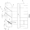
- an imaging system 40 may be used to inspect the cellular panel 20, in accordance with an embodiment of the present disclosure. More specifically, the imaging system 40 can be used to measure or quantify the actual shear angle ⁇ between the interior walls 30 of the core 26 and one of the facesheets 22, 24 by producing an image 42.
- the imaging system 40 may be configured for radiography, such as, digital or film radiography. However, other types of imaging systems may be used as well.
- the imaging system 40 includes a radiation source 44 and a detector 46 diametrically opposed to the radiation source 44.
- the radiation source 44 is configured to emit X-ray radiation, or other types of radiation, through the cellular panel 20.
- the detector 46 is configured to detect the radiation transmitted through the cellular panel 20 from the radiation source 44 and to produce an image from the detected radiation.
- the detector 46 may comprise a digital detector.
- other types of detectors 46 such as film detectors, may be used as well.
- tan ⁇ x / y
- ⁇ is the actual shear angle
- x is a projected width of the interior wall 30 onto one of the facesheets 22, 24 when a line 50 extending between the radiation source 44 and the detector 46 is parallel to, coincident, or aligned with the line 32 perpendicular to the facesheets 22, 24
- y is a thickness of the cellular panel 20.
- the cellular panel 20 is positioned at a tilt angle ⁇ relative to the line 50 extending between the radiation source 44 and the detector 46, as shown in FIG. 5 .
- the line 50 may be a straight line transmission path from the radiation source 44 through the cellular panel 20 to the detector 46.
- the tilt angle ⁇ refers to an angle between the line 32 perpendicular to the facesheets 22, 24 and the line 50 extending between the radiation source 44 and the detector 46.
- the tilt angle ⁇ is zero degrees (0°)
- the line 50 is parallel to, coincident, and/or aligned with the line 32 and perpendicular to the facesheets 22, 24.
- the tilt angle ⁇ may be between an inclusive range of twenty degrees to fifty degrees (20° - 50°). However, other values for the tilt angle ⁇ may be used.
- the radiation source 44 and the detector 46 may be moved while the cellular panel 20 is stationary. In an example shown in FIG. 6 , the cellular panel 20 may be moved to achieve the tilt angle ⁇ , while the radiation source 44 and the detector 46 are stationary. In another example, all of the cellular panel 20, the radiation source 44, and the detector 46 may be moved to achieve the tilt angle ⁇ .
- the imaging system 40 includes a control unit 52 in operative communication with the radiation source 44 and the detector 46.
- the control unit 52 is implemented using one or more of a processor, such as a "computer processor," or a processor-based device that is included or associated with a non-transitory computer readable storage medium having stored thereon computer-executable instructions.
- a processor such as a "computer processor," or a processor-based device that is included or associated with a non-transitory computer readable storage medium having stored thereon computer-executable instructions.
- One or more algorithms may be programmed into a memory 54 associated with the control unit 52.
- the memory 54 is provided within and/or external to the control unit 52, and may comprise a non-volatile memory. It is to be understood that the control unit 52 may include other hardware, software, firmware, and combinations thereof.
- a value for the tilt angle ⁇ can be programmed and stored in the memory 54 associated with the control unit 52.
- the control unit 52 is configured to rotate the radiation source 44, the detector 46, and/or the cellular panel 20 to implement the tilt angle ⁇ .
- the control unit 52 may be in communication with actuators 56, 58, 60 associated with the cellular panel 20, the radiation source 44 and the detector 46, respectively.
- the control unit 52 is programmed to send signals to one or more of the actuators 56, 58, 60 to rotate the radiation source 44, the detector 46, and/or the cellular panel 20 according to the preprogrammed value for the tilt angle ⁇ .
- each of the actuators 56, 58, 60 may include a sensor configured to detect a position of the cellular panel 20, the radiation source 44 and the detector 46 in order to verify an actual tilt angle.
- the projected shear angle ⁇ refers to a projection of the true or actual shear angle ⁇ onto the two dimensional plane of the image 62 obtained when the cellular panel 20 is at the tilt angle ⁇ .
- the projected shear angle ⁇ may be identified in the image 62 between the line 32 perpendicular to the facesheets 22, 24 and a line 64 parallel to, coincident, or aligned with the interior walls 30.
- a reference element 70 may assist in identifying the line 32 perpendicular to the facesheets 22, 24, as shown in FIGS. 1 , 3 , 5 , 6 , and 8 .
- the reference element 70 may comprise, for example, a nail including a head 72 with a shaft 74 perpendicularly extending therefrom.
- other objects may be used to assist in identification of the line 32 perpendicular to the facesheets 22, 24.
- the head 72 of the reference element 70 is temporarily attached to an outer surface 76 of one of the facesheets 22, 24.
- a length L of the shaft 74 is perpendicular to the facesheet 22.
- the shaft 74 of the reference element 70 may be used as a basis of identification for the line 32 perpendicular to the facesheets 22, 24 in the image 62. More specifically, the line 32 may follow and extend from the length L of the shaft 74 throughout the image 62. However, other techniques may be used to identify in the image 62 the line 32 perpendicular to the facesheets 22, 24.
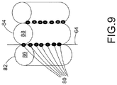
- a series of node welds 80 between interior walls 82, 84 of two adjacent cells 86, 88, respectively, may be used as a basis of identification for the line 64 parallel to the interior walls 30.
- the series of node welds 80 comprise points along a height of the walls 82, 84 where the two cells 86, 88 are bonded together.
- a straight line through each of the node welds 80 may comprise the line 64 parallel to the interior walls 30.
- other techniques may be used to identify in the image 62 the line 64 parallel to the interior walls 30.
- control unit 52 may be configured to identify in the image 62 the line 32 perpendicular to the facesheets 22, 24 and the line 64 parallel to the interior walls 30, such as, by using boundary detection.
- a user of the imaging system 40 may also identify the lines 32, 64 in the image 62, such as, on a screen or other user interface depicting the image 62.
- control unit 52 may be further configured to measure the projected shear angle ⁇ between the lines 32, 64 identified in the obtained image 62. However, the projected shear angle ⁇ may also be measured manually by the user.
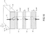
- the actual shear angle ⁇ is determined using the tilt angle ⁇ and the projected shear angle ⁇ . More specifically, the tilt angle ⁇ is achieved either by rotation of the cellular panel 20 about an axis 90, rotation of the radiation source 44 and the detector 46 about the axis 90, or a combination thereof.
- the projected width x of the interior wall 30 stays the same in each image, while the projected thicknesses d 1 , d 2 , d 3 , respectively, of the cellular panel 20 changes in each image as the tilt angle ⁇ changes.
- a user can use the equations [3] and [4] above to calculate the actual tilt angle.
- d PNL / NL * y
- d the projected thickness of the cellular panel 20
- PNL the projected length of the shaft 74 of the reference element 70
- NL the actual length of the shaft 74 of the reference element 70
- y the thickness of the cellular panel 20
- the equation [7] above is programmed into the memory 54 associated with the control unit 52.
- the control unit 52 can be configured to use the equation [7] above to determine the actual shear angle ⁇ .
- other equations than those above may also be used to determine the actual shear angle ⁇ based on the projected shear angle ⁇ . In so doing, the actual shear angle ⁇ is quantified using a non-destructive inspection technique for the cellular panel 20.
- the user can determine whether the cellular panel 20 is within predetermined specifications based on the determined actual shear angle ⁇ . More specifically, the user can compare the determined actual shear angle ⁇ to a range of predetermined specification tolerances for the shear angle of the cellular panel 20.
- the control unit 52 can be configured to determine whether the cellular panel 20 meets predetermined specification tolerances for the shear angle. For instance, predetermined specification tolerances for the shear angle of the cellular panel 20 can be programmed into the memory 54 associated with the control unit 52. The control unit 52 can further be configured to compare the determined actual shear angle ⁇ to the preprogrammed data, verify whether the determined actual shear angle ⁇ is within the predetermined specification tolerances, and notify the user.
- more than one image is obtained at different locations on the cellular panel 20.
- shear effects throughout the entire cellular panel 20 can be measured and quantified.
- a first image 100 of a first interior wall 104 is obtained at a first location 102
- a second image 106 of a second interior wall 110 is obtained at a second location 108.
- a first shear angle is determined from the first image 100
- a second shear angle is determined from the second image 106.
- the first shear angle and the second shear angle is averaged together.
- more than two images of more than two interior walls at more than two different locations may be obtained in order to get multiple shear angles for the cellular panel 20. In so doing, the average shear angle can be obtained by averaging the multiple shear angles together.
- the cellular panel 20 is positioned closer to the detector 46 than the radiation source 44, in accordance with another embodiment.
- the cellular panel 20 is not positioned closer to the detector 46 than the radiation source 44, such as, at a first position 112 near a focal point 114 of the imaging system 40, a first projected image 116 on the detector 46 may be magnified.
- magnification errors of a second projected image 120 may be reduced.
- other configurations and arrangements of the cellular panel relative to the radiation source 44 and the detector 46 may be used.
- imaging system 40 and techniques disclosed herein for shear angle quantification may be used on any object or part, and are not limited to cellular panels.
- the disclosed system and techniques provide non-destructive inspection of cellular panels and shear angle quantification of interior walls within a cellular panel. More specifically, the disclosed system and techniques use radiography to measure a shear angle of one or more interior walls within the cellular panel. In particular, by obtaining an image of the interior wall while the cellular panel is positioned at a tilt angle relative to the radiation source and detector, a user or control unit determines the actual shear angle through projected to true shear angle conversion. In so doing, the user or control unit can determine whether the cellular panel is within specification tolerances.
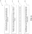
- FIG. 14 a process 130 for determining an actual shear angle ⁇ between an interior wall 30 and a facesheet 22, 24 of a cellular panel 20 using an imaging system 40 is shown, in accordance with another embodiment of the present disclosure.
- the cellular panel 20 is positioned at a tilt angle ⁇ relative to a line 50 extending between the radiation source 44 and the detector 46. Radiation is transmitted from the radiation source 44 to the detector 46 through the cellular panel 20 at the tilt angle ⁇ to obtain an image, at block 134. A projected shear angle ⁇ is measured in the obtained image, at block 136.
- the actual shear angle ⁇ between the interior wall ⁇ and the facesheet 22, 24 is determined using the tilt angle ⁇ and the projected shear angle ⁇ .
Landscapes
- Physics & Mathematics (AREA)
- General Physics & Mathematics (AREA)
- Health & Medical Sciences (AREA)
- Life Sciences & Earth Sciences (AREA)
- Chemical & Material Sciences (AREA)
- Analytical Chemistry (AREA)
- Biochemistry (AREA)
- General Health & Medical Sciences (AREA)
- Immunology (AREA)
- Pathology (AREA)
- Electromagnetism (AREA)
- Analysing Materials By The Use Of Radiation (AREA)
Description
- The present disclosure relates generally to cellular panels and, more particularly, to shear angle quantification of panels having cells.
-
US 3 090 865 A relates to a fluoroscopic inspection apparatus and more particularly to an apparatus for holding and remotely positioning a specimen into an oriented position for fluoroscopic and radiographic examination.US 3,351,760 A relates to the evaluation and inspection of adhesively bonded joints, and more particularly to the evaluation and inspection of adhesively bonded joints by the use of tracers uniformly distributed throughout the adhesive of the joint, and to structural members adapted therefor. - Some vehicles, such as aircraft, include panels having cells. For example, a panel may be composed of a honeycomb core sandwiched between two facesheets. More specifically, interior cell walls of the honeycomb core are perpendicular to the facesheets. In some situations, the cell walls of the core may move out of perpendicular orientation with the facesheets. The angle between a cell wall and one of the facesheets is referred to as the shear angle. If the shear angle is zero, the cell wall is perpendicular to the facesheet.
- Currently, in order to measure the shear angle, the panel is sliced into pieces. Each piece is then examined to determine if the shear angle is greater than zero. Typically, the shear angle is measured by hand. If the shear angle is greater than zero, the forming process for the panels can be adjusted to produce a zero shear angle. Measurements of subsequent panels and further adjustments to the forming process may be made in order to eventually achieve a zero shear angle between the cell walls of the core and the facesheets.
- In addition, non-destructive inspection of the panel may be performed using an X-ray system. However, current X-ray inspection techniques are unable to measure the shear angle between the cell walls and the facesheets. Particularly, if the X-ray system collects image data of the core from a view normal to the facesheet, a nonzero shear angle appears the same as a zero shear angle in an image generated from the collected data. Moreover, if the X-ray system collects image data of the core from a view parallel to the facesheet, the X-rays cannot transmit through the entire length of the panel, and thereby cannot produce an X-ray image.
- Accordingly, there exists a need for a non-destructive inspection technique that determines the shear angle in the interior of the panels having cells.
- In accordance with one embodiment, a method for determining an actual shear angle between an interior wall and a facesheet of a cellular panel using an imaging system is disclosed. The imaging system includes a radiation source and a detector diametrically opposed to the radiation source. The method includes positioning the cellular panel at a tilt angle relative to a line extending between the radiation source and the detector, transmitting radiation from the radiation source to the detector through the cellular panel at the tilt angle to obtain an image, measuring a projected shear angle in the obtained image, and determining the actual shear angle between the interior wall and the facesheet using the tilt angle and the projected shear angle. The method further comprises identifying the projected shear angle between a line perpendicular to the facesheet and a line extending through node welds of the interior wall. The exact features of the method according to the invention are defined in appended claim 1.
- In a refinement, the method may further comprise rotating the radiation source and the detector while the cellular panel is stationary to achieve the tilt angle.
- In another refinement, the method may further comprise rotating the cellular panel while the radiation source and the detector are stationary to achieve the tilt angle.
- In another refinement, the tilt angle may be between an inclusive range of twenty degrees to fifty degrees (20° - 50°).
- In another refinement, the method may further comprise using X-ray radiation as the radiation.
- In another refinement, the method may further comprise determining if the cellular panel is within predetermined specifications based on the determined actual shear angle.
- In another refinement, the method may further comprise calculating the actual shear angle using the tilt angle and the projected shear angle.
- In another refinement, the method may further comprise obtaining a first image of a first interior wall at a first location to determine a first actual shear angle, and obtaining a second image of a second interior wall at a second location to determine a second actual shear angle.
- In another refinement, the method may further comprise averaging the first actual shear angle and the second actual shear angle to obtain an average shear angle for the cellular panel.
- In another refinement, the method may further comprise a user of the imaging system determining the projected shear angle.
- In another refinement, the method may further comprise the imaging system automatically determining the projected shear angle using boundary detection.
- In another refinement, the method may further comprise placing a reference element on a surface of the facesheet to assist in identification of the line perpendicular to the facesheet.
- In accordance with another embodiment, an imaging system for determining an actual shear angle between an interior wall and a facesheet of a cellular panel is disclosed. The imaging system comprises a radiation source, a detector, and a control unit in operative communication with the radiation source and the detector. The detector is diametrically opposed to the radiation source and configured to detect radiation transmitted through the cellular panel from the radiation source. The control unit is configured to position the radiation source and the detector at a tilt angle relative to a line perpendicular to the facesheet of the cellular panel, transmit radiation from the radiation source through the cellular panel to the detector to obtain an image of the interior wall of the cellular panel, identify in the obtained image the line perpendicular to the facesheet, identify in the obtained image a line parallel to the interior wall, measure in the obtained image a projected shear angle between the line perpendicular to the facesheet and the line parallel to the interior wall, and determine an actual shear angle between the facesheet and the interior wall using the tilt angle and the projected shear angle. The control unit is further configured to use node welds of the interior wall in the obtained image to identify the line parallel to the interior wall, and to use a reference element attached to a surface of the facesheet in the obtained image to identify the line perpendicular to the facesheet. The exact features of the imaging unit according to the invention are defined in appended claim 9.
- In a refinement (as defined in appended claim 10), the cellular panel may be positioned closer to the detector than the radiation source.
- In accordance with another embodiment, an automated method for determining an actual shear angle between an interior wall and a facesheet of a cellular panel using an imaging system is disclosed. In said automated method the imaging system of any one of the appended claims 9 to 10 is used. The automated method may comprise moving the radiation source and the detector such that a line extending between the radiation source and the detector is at a tilt angle relative to a line perpendicular to the facesheet, acquiring an image of the interior wall by transmitting radiation from the radiation source through the cellular panel to the detector, identifying in the acquired image a projected shear angle between the line perpendicular to the facesheet and a line extending through node welds of the interior wall, measuring the projected shear angle, and determining an actual shear angle between the facesheet and the interior wall based on the tilt angle and the measured projected shear angle. The exact features of the automated method according to the invention are defined in appended claim 13. In a refinement, the automated method may further comprise using the following equation to determine the actual shear angle:

- In another refinement, the automated method may further comprise storing a value for the tilt angle between an inclusive range of twenty degrees to fifty degrees (20° - 50°) in a memory associated with the control unit. These and other aspects and features will become more readily apparent upon reading the following detailed description when taken in conjunction with the accompanying drawings.
-
-
FIG. 1 is a cross-sectional view of part of a cellular panel, in accordance with one embodiment of the present disclosure; -
FIG. 2 is a plan view of a core of the cellular panel ofFIG. 1 ; -
FIG. 3 is a cross-sectional view of part of another cellular panel; -
FIG. 4 is a side view of an imaging system, in accordance with another embodiment; -
FIG. 5 is a side view of a cellular panel with a radiation source and a detector of the imaging system ofFIG. 4 positioned at a tilt angle relative to the cellular panel; -
FIG. 6 is a side view of a cellular panel positioned at a tilt angle relative to a radiation source and a detector, in accordance with another embodiment; -
FIG. 7 is a schematic view of an imaging system, in accordance with another embodiment; -
FIG. 8 is an example X-ray image of an interior of a cellular panel obtained when the cellular panel is positioned at a tilt angle relative to a radiation source and a detector, in accordance with another embodiment; -
FIG. 9 is a schematic view of cells of the core ofFIG. 2 attached by a plurality of node welds; -
FIG. 10 is a diagrammatic view of exemplary images of a cellular panel obtained when the cellular panel is positioned at various tilt angles, in accordance with another embodiment; -
FIG. 11 is a diagrammatic view of a cellular panel and a reference element positioned at a tilt angle, in accordance with another embodiment; -
FIG. 12 is a diagrammatic view of an imaging system obtaining images of a cellular panel at two different locations on the cellular panel, in accordance with another embodiment; -
FIG. 13 is a diagrammatic view of magnification effects of an imaging system, in accordance with another embodiment; and -
FIG. 14 is a flowchart illustrating a process for determining an actual shear angle between an interior wall and a facesheet of a cellular panel using an imaging system, in accordance with another embodiment. - While the present disclosure is susceptible to various modifications and alternative constructions, certain illustrative embodiments thereof will be shown and described below in detail. The disclosure is not limited to the specific embodiments disclosed, but instead includes all modifications, alternative constructions, and equivalents thereof.
- Reference will now be made in detail to specific embodiments or features, examples of which are illustrated in the accompanying drawings. Generally, corresponding reference numbers will be used throughout the drawings to refer to the same or corresponding parts. It should be understood that the system described herein can be used with any suitable panel having cells.
-
FIG. 1 illustrates a cross-sectional view of part of a panel having cells, or acellular panel 20, consistent with certain embodiments of the present disclosure. For example, thecellular panel 20 may be made of composite material, titanium, aluminum, and the like. Thecellular panel 20 may include afirst facesheet 22 and asecond facesheet 24. Thesecond facesheet 24 may be spaced apart from and concentric to thefirst facesheet 22. A core 26 may be disposed between thefirst facesheet 22 and thesecond facesheet 24. As shown inFIG. 2 , thecore 26 includes a plurality ofcells 28, such as cells in a honeycomb configuration, although other configurations may be used for thecore 26. Each of thecells 28 are defined byinterior walls 30 of thecore 26. - Furthermore, the
cellular panel 20 may initially be manufactured such that theinterior walls 30 of the core 26 are perpendicular to each of thefirst facesheet 22 and thesecond facesheet 24. In some cases, one or more of theinterior walls 30 may be disposed at a shear angle θ relative to aline 32 perpendicular to thefirst facesheet 22 and thesecond facesheet 24, as shown inFIGS. 3 and4 . As used herein, the shear angle θ refers to an angle between theline 32 perpendicular to thefacesheets interior wall 30 of thecore 26. When the shear angle θ is zero degrees (0°), as shown inFIG. 1 , theinterior wall 30 is parallel to, coincident, or aligned with theline 32 and perpendicular to thefacesheets - As shown in
FIG. 4 , animaging system 40 may be used to inspect thecellular panel 20, in accordance with an embodiment of the present disclosure. More specifically, theimaging system 40 can be used to measure or quantify the actual shear angle θ between theinterior walls 30 of thecore 26 and one of thefacesheets image 42. For example, theimaging system 40 may be configured for radiography, such as, digital or film radiography. However, other types of imaging systems may be used as well. - The
imaging system 40 includes aradiation source 44 and adetector 46 diametrically opposed to theradiation source 44. Theradiation source 44 is configured to emit X-ray radiation, or other types of radiation, through thecellular panel 20. Thedetector 46 is configured to detect the radiation transmitted through thecellular panel 20 from theradiation source 44 and to produce an image from the detected radiation. For example, thedetector 46 may comprise a digital detector. However, other types ofdetectors 46, such as film detectors, may be used as well. - From the diagram in
FIG. 4 , the following equation for the actual shear angle θ is derived:
interior wall 30 onto one of thefacesheets line 50 extending between theradiation source 44 and thedetector 46 is parallel to, coincident, or aligned with theline 32 perpendicular to thefacesheets cellular panel 20. - In order to determine the shear angle θ, the
cellular panel 20 is positioned at a tilt angle φ relative to theline 50 extending between theradiation source 44 and thedetector 46, as shown inFIG. 5 . For example, theline 50 may be a straight line transmission path from theradiation source 44 through thecellular panel 20 to thedetector 46. As used herein, the tilt angle φ refers to an angle between theline 32 perpendicular to thefacesheets line 50 extending between theradiation source 44 and thedetector 46. When the tilt angle φ is zero degrees (0°), theline 50 is parallel to, coincident, and/or aligned with theline 32 and perpendicular to thefacesheets - For instance, the tilt angle φ may be between an inclusive range of twenty degrees to fifty degrees (20° - 50°). However, other values for the tilt angle φ may be used. To achieve the tilt angle φ, the
radiation source 44 and thedetector 46 may be moved while thecellular panel 20 is stationary. In an example shown inFIG. 6 , thecellular panel 20 may be moved to achieve the tilt angle φ, while theradiation source 44 and thedetector 46 are stationary. In another example, all of thecellular panel 20, theradiation source 44, and thedetector 46 may be moved to achieve the tilt angle φ. - Referring now to
FIG. 7 , with continued reference toFIGS. 1-6 , theimaging system 40 includes acontrol unit 52 in operative communication with theradiation source 44 and thedetector 46. Thecontrol unit 52 is implemented using one or more of a processor, such as a "computer processor," or a processor-based device that is included or associated with a non-transitory computer readable storage medium having stored thereon computer-executable instructions. One or more algorithms may be programmed into amemory 54 associated with thecontrol unit 52. Thememory 54 is provided within and/or external to thecontrol unit 52, and may comprise a non-volatile memory. It is to be understood that thecontrol unit 52 may include other hardware, software, firmware, and combinations thereof. - Furthermore, a value for the tilt angle φ can be programmed and stored in the
memory 54 associated with thecontrol unit 52. Thecontrol unit 52 is configured to rotate theradiation source 44, thedetector 46, and/or thecellular panel 20 to implement the tilt angle φ. For example, thecontrol unit 52 may be in communication withactuators cellular panel 20, theradiation source 44 and thedetector 46, respectively. Thecontrol unit 52 is programmed to send signals to one or more of theactuators radiation source 44, thedetector 46, and/or thecellular panel 20 according to the preprogrammed value for the tilt angle φ. In addition, each of theactuators cellular panel 20, theradiation source 44 and thedetector 46 in order to verify an actual tilt angle. - When the
cellular panel 20 is positioned at the tilt angle φ relative to theline 50 extending between theradiation source 44 and thedetector 46, radiation from theradiation source 44 is transmitted through thecellular panel 20 to thedetector 46 to obtain an image, such as, theexample image 62 shown inFIG. 8 . From the obtainedimage 62, a projected shear angle α is determined. The projected shear angle α refers to a projection of the true or actual shear angle θ onto the two dimensional plane of theimage 62 obtained when thecellular panel 20 is at the tilt angle φ. For instance, the projected shear angle α may be identified in theimage 62 between theline 32 perpendicular to thefacesheets line 64 parallel to, coincident, or aligned with theinterior walls 30. - A
reference element 70 may assist in identifying theline 32 perpendicular to thefacesheets FIGS. 1 ,3 ,5 ,6 , and8 . Thereference element 70 may comprise, for example, a nail including ahead 72 with ashaft 74 perpendicularly extending therefrom. However, other objects may be used to assist in identification of theline 32 perpendicular to thefacesheets head 72 of thereference element 70 is temporarily attached to anouter surface 76 of one of thefacesheets - With the
head 72 of thereference element 70 oriented parallel or tangent to theouter surface 76 of thefacesheet 22, a length L of theshaft 74 is perpendicular to thefacesheet 22. After theimage 62, inFIG. 8 , is obtained with thereference element 70 attached to thefacesheet 22, theshaft 74 of thereference element 70 may be used as a basis of identification for theline 32 perpendicular to thefacesheets image 62. More specifically, theline 32 may follow and extend from the length L of theshaft 74 throughout theimage 62. However, other techniques may be used to identify in theimage 62 theline 32 perpendicular to thefacesheets - Referring now to
FIG. 9 , with continued reference toFIGS. 1-8 , a series of node welds 80 betweeninterior walls adjacent cells line 64 parallel to theinterior walls 30. The series of node welds 80 comprise points along a height of thewalls cells image 62 ofFIG. 8 , by identifying the series of node welds 80, a straight line through each of the node welds 80 may comprise theline 64 parallel to theinterior walls 30. However, other techniques may be used to identify in theimage 62 theline 64 parallel to theinterior walls 30. - In addition, the
control unit 52 may be configured to identify in theimage 62 theline 32 perpendicular to thefacesheets line 64 parallel to theinterior walls 30, such as, by using boundary detection. A user of theimaging system 40 may also identify thelines image 62, such as, on a screen or other user interface depicting theimage 62. Moreover, thecontrol unit 52 may be further configured to measure the projected shear angle α between thelines image 62. However, the projected shear angle α may also be measured manually by the user. - Turning now to
FIG. 10 , with continued reference toFIGS. 1-9 , the actual shear angle θ is determined using the tilt angle φ and the projected shear angle α. More specifically, the tilt angle φ is achieved either by rotation of thecellular panel 20 about anaxis 90, rotation of theradiation source 44 and thedetector 46 about theaxis 90, or a combination thereof. After an image, such as an X-ray image, is obtained at a tilt angle φ, the projected shear angle α represented in the obtained image may be determined based on the following equation:
interior wall 30 onto one of thefacesheets line 50 extending between theradiation source 44 and thedetector 46 is parallel to, coincident, or aligned with theline 32 perpendicular to thefacesheets cellular panel 20 onto the two dimensional plane of the image obtained at the tilt angle φ. As shown inimages interior wall 30 stays the same in each image, while the projected thicknesses d1, d2, d3, respectively, of thecellular panel 20 changes in each image as the tilt angle φ changes. - Referring now to
FIG. 11 , with continued reference toFIGS. 1-10 , the following equation for the tilt angle φ is derived:
cellular panel 20, and y is the thickness of thecellular panel 20. In addition, using thereference element 70, another equation for the tilt angle φ is derived fromFIG. 11 as follows:
shaft 74 of thereference element 70, and NL is an actual nail length or an actual length of theshaft 74 of thereference element 70. A user can use the equations [3] and [4] above to calculate the actual tilt angle. - Moreover, based on the equations [3] and [4] above for the tilt angle φ, the following equation for the projected thickness of the
cellular panel 20 is derived:
cellular panel 20, PNL is the projected length of theshaft 74 of thereference element 70, NL is the actual length of theshaft 74 of thereference element 70, and y is the thickness of thecellular panel 20. - By substituting the equation [5] for the projected thickness d of the
cellular panel 20 into the equation [2] above for the projected shear angle α, the following equation for the thickness y of thecellular panel 20 is derived:
cellular panel 20; NL is the actual length of theshaft 74 of thereference element 70; x is the projected width of theinterior wall 30 onto one of thefacesheets line 50 extending between theradiation source 44 and thedetector 46 is parallel to, coincident, or aligned with theline 32 perpendicular to thefacesheets shaft 74 of thereference element 70; and α is the projected shear angle. - Furthermore, substituting the equation [4] above for the tilt angle φ and the equation [6] above for the thickness y of the
cellular panel 20 into the equation [1] above for the actual shear angle θ results in the following equation:
- In another embodiment, the equation [7] above is programmed into the
memory 54 associated with thecontrol unit 52. For instance, using the detected tilt angle φ from the sensor and the projected shear angle α previously measured using boundary detection, thecontrol unit 52 can be configured to use the equation [7] above to determine the actual shear angle θ. However, other equations than those above may also be used to determine the actual shear angle θ based on the projected shear angle α. In so doing, the actual shear angle θ is quantified using a non-destructive inspection technique for thecellular panel 20. - Furthermore, the user can determine whether the
cellular panel 20 is within predetermined specifications based on the determined actual shear angle θ. More specifically, the user can compare the determined actual shear angle θ to a range of predetermined specification tolerances for the shear angle of thecellular panel 20. In another example, thecontrol unit 52 can be configured to determine whether thecellular panel 20 meets predetermined specification tolerances for the shear angle. For instance, predetermined specification tolerances for the shear angle of thecellular panel 20 can be programmed into thememory 54 associated with thecontrol unit 52. Thecontrol unit 52 can further be configured to compare the determined actual shear angle θ to the preprogrammed data, verify whether the determined actual shear angle θ is within the predetermined specification tolerances, and notify the user. - Referring now to
FIG. 12 , with continued reference toFIGS. 1-11 , more than one image is obtained at different locations on thecellular panel 20. By obtaining various images of different interior walls, shear effects throughout the entirecellular panel 20 can be measured and quantified. For instance, afirst image 100 of a firstinterior wall 104 is obtained at afirst location 102, and asecond image 106 of a secondinterior wall 110 is obtained at asecond location 108. A first shear angle is determined from thefirst image 100, and a second shear angle is determined from thesecond image 106. To obtain an average shear angle for thecellular panel 20, the first shear angle and the second shear angle is averaged together. Furthermore, more than two images of more than two interior walls at more than two different locations may be obtained in order to get multiple shear angles for thecellular panel 20. In so doing, the average shear angle can be obtained by averaging the multiple shear angles together. - Furthermore, as shown in
FIG. 13 , thecellular panel 20 is positioned closer to thedetector 46 than theradiation source 44, in accordance with another embodiment. For example, when thecellular panel 20 is not positioned closer to thedetector 46 than theradiation source 44, such as, at afirst position 112 near afocal point 114 of theimaging system 40, a first projectedimage 116 on thedetector 46 may be magnified. When thecellular panel 20 is positioned closer to thedetector 46 than theradiation source 44, such as, at asecond position 118, magnification errors of a second projectedimage 120 may be reduced. However, other configurations and arrangements of the cellular panel relative to theradiation source 44 and thedetector 46 may be used. - It is to be understood that the
imaging system 40 and techniques disclosed herein for shear angle quantification may be used on any object or part, and are not limited to cellular panels. - In general, the foregoing disclosure finds utility in various applications relating to cellular panels. The disclosed system and techniques provide non-destructive inspection of cellular panels and shear angle quantification of interior walls within a cellular panel. More specifically, the disclosed system and techniques use radiography to measure a shear angle of one or more interior walls within the cellular panel. In particular, by obtaining an image of the interior wall while the cellular panel is positioned at a tilt angle relative to the radiation source and detector, a user or control unit determines the actual shear angle through projected to true shear angle conversion. In so doing, the user or control unit can determine whether the cellular panel is within specification tolerances.
- Turning now to
FIG. 14 , with continued reference toFIGS. 1-13 , aprocess 130 for determining an actual shear angle θ between aninterior wall 30 and afacesheet cellular panel 20 using animaging system 40 is shown, in accordance with another embodiment of the present disclosure. Atblock 132, thecellular panel 20 is positioned at a tilt angle φ relative to aline 50 extending between theradiation source 44 and thedetector 46. Radiation is transmitted from theradiation source 44 to thedetector 46 through thecellular panel 20 at the tilt angle φ to obtain an image, atblock 134. A projected shear angle α is measured in the obtained image, atblock 136. Atblock 138, the actual shear angle θ between the interior wall θ and thefacesheet - It is to be understood that the flowchart in
FIG. 14 is shown and described as an example only to assist in disclosing the features of the disclosed system and techniques, and that more or less steps than that shown may be included in the process corresponding to the various features described above for the disclosed system without departing from the scope of the disclosure. - While the foregoing detailed description has been given and provided with respect to certain specific embodiments, it is to be understood that the scope of the disclosure should not be limited to such embodiments, but that the same are provided simply for enablement and best mode purposes. The scope of the present invention is defined by the appended claims.
Claims (13)
- A process (130) for determining an actual shear angle (θ) between an interior wall (30) and a facesheet (22, 24) of a cellular panel (20) using an imaging system (40), the imaging system including a radiation source (44) and a detector (46) diametrically opposed to the radiation source, the method comprising:positioning (132) the cellular panel at a tilt angle (φ) relative to a line (50) extending between the radiation source and the detector;transmitting (134) radiation from the radiation source to the detector through the cellular panel at the tilt angle to obtain an image (62);measuring (136) a projected shear angle (α) in the obtained image;determining (138) the actual shear angle between the interior wall and the facesheet using the tilt angle and the projected shear angle, andidentifying the projected shear angle (α) between a line (32) perpendicular to the facesheet (22, 24) and a line (64) extending through node welds (80) of the interior wall (30, 82, 84).
- The process (130) of claim 1, further comprising:rotating the radiation source (44) and the detector (46) while the cellular panel (20) is stationary to achieve the tilt angle (φ); orrotating the cellular panel while the radiation source and the detector are stationary to achieve the tilt angle.
- The process (130) of claim 1 or 2, wherein the tilt angle (φ) is between an inclusive range of twenty degrees to fifty degrees (20° - 50°).
- The process (130) of any one of claims 1 to 3, further comprising determining if the cellular panel (20) is within predetermined specifications based on the determined actual shear angle (θ).
- The process (130) of any one of claims 1 to 4, further comprising calculating the actual shear angle (θ) using the tilt angle (φ) and the projected shear angle (α).
- The process (130) of any one of claims 1 to 5, further comprising obtaining a first image (100) of a first interior wall (30, 104) at a first location (102) to determine a first actual shear angle, and obtaining a second image (106) of a second interior wall (30, 110) at a second location (108) to determine a second actual shear angle, preferably further comprising averaging the first actual shear angle and the second actual shear angle to obtain an average shear angle for the cellular panel (20).
- The process (130) of any one of claims 1 to 6, further comprising placing a reference element (70) on a surface (76) of the facesheet to assist in identification of the line perpendicular to the facesheet.
- The process (130) of claim 7, further comprising:a user of the imaging system (40) determining the projected shear angle (α); orthe imaging system automatically determining the projected shear angle using boundary detection.
- An imaging system (40) for determining an actual shear angle (θ) between an interior wall (30) and a facesheet (22, 24) of a cellular panel (20), the imaging system comprising:a radiation source (44);a detector (46) diametrically opposed to the radiation source and configured to detect radiation transmitted through the cellular panel from the radiation source; anda control unit (52) in operative communication with the radiation source and the detector, the control unit (52) configured to:position the radiation source and the detector at a tilt angle (φ) relative to a line (50) perpendicular to the facesheet of the cellular panel,transmit radiation from the radiation source through the cellular panel to the detector to obtain an image (62) of the interior wall of the cellular panel,identify in the obtained image a line (32) perpendicular to the facesheet,identify in the obtained image a line (64) parallel to the interior wall,measure in the obtained image a projected shear angle (α) between the line perpendicular to the facesheet and the line parallel to the interior wall, anddetermine the actual shear angle between the facesheet and the interior wall using the tilt angle and the projected shear angle,wherein the control unit (52) is configured to use node welds (80) of the interior wall (30, 82, 84) in the obtained image (62) to identify the line (64) parallel to the interior wall, and to use a reference element (70) attached to a surface (76) of the facesheet (22, 24) in the obtained image (62) to identify the line (32) perpendicular to the facesheet.
- The imaging system (40) of claim 9, wherein the cellular panel (20) is positioned closer to the detector (46) than the radiation source (44).
- An automated method for determining the actual shear angle (θ) between the interior wall (30, 82, 84) and the facesheet (22, 24) of the cellular panel (20) using the imaging system (40) of any one of Claims 9 to 10, the automated method comprising:moving the radiation source (44) and the detector (46) such that the line (50) extending between the radiation source and the detector is at the tilt angle (φ) relative to the line (32) perpendicular to the facesheet;acquiring the image (62) of the interior wall by transmitting radiation from the radiation source through the cellular panel to the detector;identifying in the acquired image the projected shear angle (α) between the line perpendicular to the facesheet and the line (64) extending through node welds (80) of the interior wall;measuring the projected shear angle; anddetermining the actual shear angle between the facesheet and the interior wall based on the tilt angle and the measured projected shear angle.
- The automated method of claim 11, further comprising using the following equation to determine the actual shear angle (θ):

- The automated method of claim 11 or 12, further comprising storing a value for the tilt angle (φ) between an inclusive range of twenty degrees to fifty degrees (20° - 50°) in a memory (54) associated with the control unit (52).
Applications Claiming Priority (1)
| Application Number | Priority Date | Filing Date | Title |
|---|---|---|---|
| US14/821,267 US9880112B2 (en) | 2015-08-07 | 2015-08-07 | Methods and system for determining shear angle |
Publications (2)
| Publication Number | Publication Date |
|---|---|
| EP3128290A1 EP3128290A1 (en) | 2017-02-08 |
| EP3128290B1 true EP3128290B1 (en) | 2018-03-14 |
Family
ID=56296475
Family Applications (1)
| Application Number | Title | Priority Date | Filing Date |
|---|---|---|---|
| EP16172864.7A Active EP3128290B1 (en) | 2015-08-07 | 2016-06-03 | Methods and system for determining shear angle |
Country Status (2)
| Country | Link |
|---|---|
| US (1) | US9880112B2 (en) |
| EP (1) | EP3128290B1 (en) |
Families Citing this family (3)
| Publication number | Priority date | Publication date | Assignee | Title |
|---|---|---|---|---|
| CN109558647B (en) * | 2018-11-07 | 2023-01-13 | 中国航空工业集团公司西安飞机设计研究所 | CATIA-based rapid modeling method for similar parts |
| CN110232388B (en) * | 2019-06-11 | 2023-01-17 | 大连理工大学 | A method for identifying honeycomb edges from honeycomb core surface measurement data |
| CN121430502A (en) * | 2025-10-31 | 2026-01-30 | 京东方科技集团股份有限公司 | Angle testing methods and systems, and membrane cutting methods |
Family Cites Families (4)
| Publication number | Priority date | Publication date | Assignee | Title |
|---|---|---|---|---|
| US3090865A (en) * | 1959-11-02 | 1963-05-21 | Justin G Schneeman | Fluoroscopic inspection apparatus |
| US3351760A (en) | 1963-08-26 | 1967-11-07 | Robert L Brown | Methods of evaluating and inspecting adhesively bonded joints and structures adapted for such evaluation and inspection |
| US4969110A (en) * | 1988-08-01 | 1990-11-06 | General Electric Company | Method of using a priori information in computerized tomography |
| US6047041A (en) * | 1997-09-08 | 2000-04-04 | Scientific Measurement System | Apparatus and method for comparison |
-
2015
- 2015-08-07 US US14/821,267 patent/US9880112B2/en not_active Expired - Fee Related
-
2016
- 2016-06-03 EP EP16172864.7A patent/EP3128290B1/en active Active
Non-Patent Citations (1)
| Title |
|---|
| None * |
Also Published As
| Publication number | Publication date |
|---|---|
| US20170038313A1 (en) | 2017-02-09 |
| US9880112B2 (en) | 2018-01-30 |
| EP3128290A1 (en) | 2017-02-08 |
Similar Documents
| Publication | Publication Date | Title |
|---|---|---|
| JP6091507B2 (en) | Determination of deflection of compression elements based on images | |
| EP3074761B1 (en) | Calibration apparatus and method for computed tomography | |
| JP6144779B2 (en) | Method and system for ultrasonic inspection of inspection object by manual operation | |
| Rodríguez-Martín et al. | Macro-photogrammetry as a tool for the accurate measurement of three-dimensional misalignment in welding | |
| CN111351798B (en) | Dynamic Position Data Correction Using Non-Destructive Inspection | |
| EP3775860B1 (en) | Computed tomographic system calibration | |
| WO2017107607A1 (en) | Portable backscatter imaging examination device and imaging method | |
| US20160349193A1 (en) | Apparatus and method for examining components comprising laid fiber composite fabrics or woven fiber composite fabrics | |
| EP3128290A1 (en) | Methods and system for determining shear angle | |
| KR20180057615A (en) | Determination of the orientation of an edge-on x-ray detector with respect to the direction of the incident x-ray | |
| JP2014009976A (en) | Three-dimensional shape measurement x-ray ct device and three-dimensional shape measurement method by x-ray ct device | |
| US20130223722A1 (en) | Method and evaluation device for determining the position of a structure located in an object to be examined by means of x-ray computer tomography | |
| CN107307874B (en) | Method for operating an X-ray system and X-ray system | |
| JP5994299B2 (en) | X-ray equipment | |
| CN115452944B (en) | Multiple damage location method for plate materials based on L-shaped sensor cluster | |
| JP5385786B2 (en) | Arrangements and methods for non-destructive measurement of object thickness and surface shape | |
| JP7008325B2 (en) | Radiation fluoroscopy non-destructive inspection method and radiation fluoroscopy non-destructive inspection equipment | |
| CN108267711B (en) | Sensor distance adjusting method and device | |
| US9465046B1 (en) | Inertial sensor apparatus and method for creating an NDI image with hand scanning | |
| CN111272625B (en) | A porosity evaluation method, device, equipment and storage medium | |
| US20220163434A1 (en) | Strength evaluation device and strength evaluation method | |
| US9772259B2 (en) | Method for calibrating an X-ray testing system for a tire type and method for checking the position of cords in a tire | |
| US6173030B1 (en) | Almost-everywhere extrapolation using 2D transforms from cone-beam data | |
| US20160253827A1 (en) | Method for determining the danger zone between a test object and an x-ray inspection system | |
| US9691159B2 (en) | Local contraction measurements |
Legal Events
| Date | Code | Title | Description |
|---|---|---|---|
| PUAI | Public reference made under article 153(3) epc to a published international application that has entered the european phase |
Free format text: ORIGINAL CODE: 0009012 |
|
| 17P | Request for examination filed |
Effective date: 20160603 |
|
| AK | Designated contracting states |
Kind code of ref document: A1 Designated state(s): AL AT BE BG CH CY CZ DE DK EE ES FI FR GB GR HR HU IE IS IT LI LT LU LV MC MK MT NL NO PL PT RO RS SE SI SK SM TR |
|
| AX | Request for extension of the european patent |
Extension state: BA ME |
|
| RBV | Designated contracting states (corrected) |
Designated state(s): AL AT BE BG CH CY CZ DE DK EE ES FI FR GB GR HR HU IE IS IT LI LT LU LV MC MK MT NL NO PL PT RO RS SE SI SK SM TR |
|
| GRAP | Despatch of communication of intention to grant a patent |
Free format text: ORIGINAL CODE: EPIDOSNIGR1 |
|
| RIC1 | Information provided on ipc code assigned before grant |
Ipc: G01N 1/00 20060101ALI20170823BHEP Ipc: G01N 23/00 20060101ALI20170823BHEP Ipc: B32B 3/00 20060101ALI20170823BHEP Ipc: G01N 23/04 20060101ALI20170823BHEP Ipc: G01B 15/00 20060101AFI20170823BHEP |
|
| INTG | Intention to grant announced |
Effective date: 20170915 |
|
| GRAS | Grant fee paid |
Free format text: ORIGINAL CODE: EPIDOSNIGR3 |
|
| GRAA | (expected) grant |
Free format text: ORIGINAL CODE: 0009210 |
|
| AK | Designated contracting states |
Kind code of ref document: B1 Designated state(s): AL AT BE BG CH CY CZ DE DK EE ES FI FR GB GR HR HU IE IS IT LI LT LU LV MC MK MT NL NO PL PT RO RS SE SI SK SM TR |
|
| REG | Reference to a national code |
Ref country code: GB Ref legal event code: FG4D |
|
| REG | Reference to a national code |
Ref country code: CH Ref legal event code: EP Ref country code: AT Ref legal event code: REF Ref document number: 979333 Country of ref document: AT Kind code of ref document: T Effective date: 20180315 |
|
| REG | Reference to a national code |
Ref country code: IE Ref legal event code: FG4D |
|
| REG | Reference to a national code |
Ref country code: DE Ref legal event code: R096 Ref document number: 602016001963 Country of ref document: DE |
|
| REG | Reference to a national code |
Ref country code: CH Ref legal event code: NV Representative=s name: ISLER AND PEDRAZZINI AG, CH |
|
| REG | Reference to a national code |
Ref country code: FR Ref legal event code: PLFP Year of fee payment: 3 |
|
| REG | Reference to a national code |
Ref country code: NL Ref legal event code: MP Effective date: 20180314 |
|
| REG | Reference to a national code |
Ref country code: LT Ref legal event code: MG4D |
|
| PG25 | Lapsed in a contracting state [announced via postgrant information from national office to epo] |
Ref country code: CY Free format text: LAPSE BECAUSE OF FAILURE TO SUBMIT A TRANSLATION OF THE DESCRIPTION OR TO PAY THE FEE WITHIN THE PRESCRIBED TIME-LIMIT Effective date: 20180314 Ref country code: LT Free format text: LAPSE BECAUSE OF FAILURE TO SUBMIT A TRANSLATION OF THE DESCRIPTION OR TO PAY THE FEE WITHIN THE PRESCRIBED TIME-LIMIT Effective date: 20180314 Ref country code: FI Free format text: LAPSE BECAUSE OF FAILURE TO SUBMIT A TRANSLATION OF THE DESCRIPTION OR TO PAY THE FEE WITHIN THE PRESCRIBED TIME-LIMIT Effective date: 20180314 Ref country code: NO Free format text: LAPSE BECAUSE OF FAILURE TO SUBMIT A TRANSLATION OF THE DESCRIPTION OR TO PAY THE FEE WITHIN THE PRESCRIBED TIME-LIMIT Effective date: 20180614 Ref country code: HR Free format text: LAPSE BECAUSE OF FAILURE TO SUBMIT A TRANSLATION OF THE DESCRIPTION OR TO PAY THE FEE WITHIN THE PRESCRIBED TIME-LIMIT Effective date: 20180314 |
|
| REG | Reference to a national code |
Ref country code: AT Ref legal event code: MK05 Ref document number: 979333 Country of ref document: AT Kind code of ref document: T Effective date: 20180314 |
|
| PG25 | Lapsed in a contracting state [announced via postgrant information from national office to epo] |
Ref country code: BG Free format text: LAPSE BECAUSE OF FAILURE TO SUBMIT A TRANSLATION OF THE DESCRIPTION OR TO PAY THE FEE WITHIN THE PRESCRIBED TIME-LIMIT Effective date: 20180614 Ref country code: SE Free format text: LAPSE BECAUSE OF FAILURE TO SUBMIT A TRANSLATION OF THE DESCRIPTION OR TO PAY THE FEE WITHIN THE PRESCRIBED TIME-LIMIT Effective date: 20180314 Ref country code: RS Free format text: LAPSE BECAUSE OF FAILURE TO SUBMIT A TRANSLATION OF THE DESCRIPTION OR TO PAY THE FEE WITHIN THE PRESCRIBED TIME-LIMIT Effective date: 20180314 Ref country code: LV Free format text: LAPSE BECAUSE OF FAILURE TO SUBMIT A TRANSLATION OF THE DESCRIPTION OR TO PAY THE FEE WITHIN THE PRESCRIBED TIME-LIMIT Effective date: 20180314 Ref country code: GR Free format text: LAPSE BECAUSE OF FAILURE TO SUBMIT A TRANSLATION OF THE DESCRIPTION OR TO PAY THE FEE WITHIN THE PRESCRIBED TIME-LIMIT Effective date: 20180615 |
|
| PG25 | Lapsed in a contracting state [announced via postgrant information from national office to epo] |
Ref country code: IT Free format text: LAPSE BECAUSE OF FAILURE TO SUBMIT A TRANSLATION OF THE DESCRIPTION OR TO PAY THE FEE WITHIN THE PRESCRIBED TIME-LIMIT Effective date: 20180314 Ref country code: PL Free format text: LAPSE BECAUSE OF FAILURE TO SUBMIT A TRANSLATION OF THE DESCRIPTION OR TO PAY THE FEE WITHIN THE PRESCRIBED TIME-LIMIT Effective date: 20180314 Ref country code: EE Free format text: LAPSE BECAUSE OF FAILURE TO SUBMIT A TRANSLATION OF THE DESCRIPTION OR TO PAY THE FEE WITHIN THE PRESCRIBED TIME-LIMIT Effective date: 20180314 Ref country code: RO Free format text: LAPSE BECAUSE OF FAILURE TO SUBMIT A TRANSLATION OF THE DESCRIPTION OR TO PAY THE FEE WITHIN THE PRESCRIBED TIME-LIMIT Effective date: 20180314 Ref country code: NL Free format text: LAPSE BECAUSE OF FAILURE TO SUBMIT A TRANSLATION OF THE DESCRIPTION OR TO PAY THE FEE WITHIN THE PRESCRIBED TIME-LIMIT Effective date: 20180314 Ref country code: ES Free format text: LAPSE BECAUSE OF FAILURE TO SUBMIT A TRANSLATION OF THE DESCRIPTION OR TO PAY THE FEE WITHIN THE PRESCRIBED TIME-LIMIT Effective date: 20180314 Ref country code: AL Free format text: LAPSE BECAUSE OF FAILURE TO SUBMIT A TRANSLATION OF THE DESCRIPTION OR TO PAY THE FEE WITHIN THE PRESCRIBED TIME-LIMIT Effective date: 20180314 |
|
| PG25 | Lapsed in a contracting state [announced via postgrant information from national office to epo] |
Ref country code: AT Free format text: LAPSE BECAUSE OF FAILURE TO SUBMIT A TRANSLATION OF THE DESCRIPTION OR TO PAY THE FEE WITHIN THE PRESCRIBED TIME-LIMIT Effective date: 20180314 Ref country code: SM Free format text: LAPSE BECAUSE OF FAILURE TO SUBMIT A TRANSLATION OF THE DESCRIPTION OR TO PAY THE FEE WITHIN THE PRESCRIBED TIME-LIMIT Effective date: 20180314 Ref country code: SK Free format text: LAPSE BECAUSE OF FAILURE TO SUBMIT A TRANSLATION OF THE DESCRIPTION OR TO PAY THE FEE WITHIN THE PRESCRIBED TIME-LIMIT Effective date: 20180314 Ref country code: CZ Free format text: LAPSE BECAUSE OF FAILURE TO SUBMIT A TRANSLATION OF THE DESCRIPTION OR TO PAY THE FEE WITHIN THE PRESCRIBED TIME-LIMIT Effective date: 20180314 |
|
| REG | Reference to a national code |
Ref country code: DE Ref legal event code: R097 Ref document number: 602016001963 Country of ref document: DE |
|
| PG25 | Lapsed in a contracting state [announced via postgrant information from national office to epo] |
Ref country code: PT Free format text: LAPSE BECAUSE OF FAILURE TO SUBMIT A TRANSLATION OF THE DESCRIPTION OR TO PAY THE FEE WITHIN THE PRESCRIBED TIME-LIMIT Effective date: 20180716 |
|
| PLBE | No opposition filed within time limit |
Free format text: ORIGINAL CODE: 0009261 |
|
| STAA | Information on the status of an ep patent application or granted ep patent |
Free format text: STATUS: NO OPPOSITION FILED WITHIN TIME LIMIT |
|
| PG25 | Lapsed in a contracting state [announced via postgrant information from national office to epo] |
Ref country code: DK Free format text: LAPSE BECAUSE OF FAILURE TO SUBMIT A TRANSLATION OF THE DESCRIPTION OR TO PAY THE FEE WITHIN THE PRESCRIBED TIME-LIMIT Effective date: 20180314 |
|
| 26N | No opposition filed |
Effective date: 20181217 |
|
| PG25 | Lapsed in a contracting state [announced via postgrant information from national office to epo] |
Ref country code: SI Free format text: LAPSE BECAUSE OF FAILURE TO SUBMIT A TRANSLATION OF THE DESCRIPTION OR TO PAY THE FEE WITHIN THE PRESCRIBED TIME-LIMIT Effective date: 20180314 |
|
| REG | Reference to a national code |
Ref country code: BE Ref legal event code: MM Effective date: 20180630 |
|
| REG | Reference to a national code |
Ref country code: IE Ref legal event code: MM4A |
|
| PG25 | Lapsed in a contracting state [announced via postgrant information from national office to epo] |
Ref country code: MC Free format text: LAPSE BECAUSE OF FAILURE TO SUBMIT A TRANSLATION OF THE DESCRIPTION OR TO PAY THE FEE WITHIN THE PRESCRIBED TIME-LIMIT Effective date: 20180314 Ref country code: LU Free format text: LAPSE BECAUSE OF NON-PAYMENT OF DUE FEES Effective date: 20180603 |
|
| PG25 | Lapsed in a contracting state [announced via postgrant information from national office to epo] |
Ref country code: IE Free format text: LAPSE BECAUSE OF NON-PAYMENT OF DUE FEES Effective date: 20180603 |
|
| PG25 | Lapsed in a contracting state [announced via postgrant information from national office to epo] |
Ref country code: BE Free format text: LAPSE BECAUSE OF NON-PAYMENT OF DUE FEES Effective date: 20180630 |
|
| PG25 | Lapsed in a contracting state [announced via postgrant information from national office to epo] |
Ref country code: MT Free format text: LAPSE BECAUSE OF NON-PAYMENT OF DUE FEES Effective date: 20180603 |
|
| PG25 | Lapsed in a contracting state [announced via postgrant information from national office to epo] |
Ref country code: TR Free format text: LAPSE BECAUSE OF FAILURE TO SUBMIT A TRANSLATION OF THE DESCRIPTION OR TO PAY THE FEE WITHIN THE PRESCRIBED TIME-LIMIT Effective date: 20180314 |
|
| PG25 | Lapsed in a contracting state [announced via postgrant information from national office to epo] |
Ref country code: MK Free format text: LAPSE BECAUSE OF NON-PAYMENT OF DUE FEES Effective date: 20180314 Ref country code: HU Free format text: LAPSE BECAUSE OF FAILURE TO SUBMIT A TRANSLATION OF THE DESCRIPTION OR TO PAY THE FEE WITHIN THE PRESCRIBED TIME-LIMIT; INVALID AB INITIO Effective date: 20160603 |
|
| PG25 | Lapsed in a contracting state [announced via postgrant information from national office to epo] |
Ref country code: IS Free format text: LAPSE BECAUSE OF FAILURE TO SUBMIT A TRANSLATION OF THE DESCRIPTION OR TO PAY THE FEE WITHIN THE PRESCRIBED TIME-LIMIT Effective date: 20180714 |
|
| P01 | Opt-out of the competence of the unified patent court (upc) registered |
Effective date: 20230516 |
|
| PGFP | Annual fee paid to national office [announced via postgrant information from national office to epo] |
Ref country code: GB Payment date: 20240627 Year of fee payment: 9 |
|
| PGFP | Annual fee paid to national office [announced via postgrant information from national office to epo] |
Ref country code: DE Payment date: 20240627 Year of fee payment: 9 |
|
| PGFP | Annual fee paid to national office [announced via postgrant information from national office to epo] |
Ref country code: FR Payment date: 20240625 Year of fee payment: 9 |
|
| PGFP | Annual fee paid to national office [announced via postgrant information from national office to epo] |
Ref country code: CH Payment date: 20240704 Year of fee payment: 9 |
|
| REG | Reference to a national code |
Ref country code: DE Ref legal event code: R119 Ref document number: 602016001963 Country of ref document: DE |
|
| REG | Reference to a national code |
Ref country code: CH Ref legal event code: H13 Free format text: ST27 STATUS EVENT CODE: U-0-0-H10-H13 (AS PROVIDED BY THE NATIONAL OFFICE) Effective date: 20260127 |
|
| GBPC | Gb: european patent ceased through non-payment of renewal fee |
Effective date: 20250603 |
|
| PG25 | Lapsed in a contracting state [announced via postgrant information from national office to epo] |
Ref country code: GB Free format text: LAPSE BECAUSE OF NON-PAYMENT OF DUE FEES Effective date: 20250603 |
|
| PG25 | Lapsed in a contracting state [announced via postgrant information from national office to epo] |
Ref country code: DE Free format text: LAPSE BECAUSE OF NON-PAYMENT OF DUE FEES Effective date: 20260101 |
|
| PG25 | Lapsed in a contracting state [announced via postgrant information from national office to epo] |
Ref country code: FR Free format text: LAPSE BECAUSE OF NON-PAYMENT OF DUE FEES Effective date: 20250630 |
|
| PG25 | Lapsed in a contracting state [announced via postgrant information from national office to epo] |
Ref country code: CH Free format text: LAPSE BECAUSE OF NON-PAYMENT OF DUE FEES Effective date: 20250630 |