EP3128151A1 - Gas turbine cycle equipment, equipment for recovering co2 from exhaust gas, and method for recovering exhaust heat from combustion exhaust gas - Google Patents
Gas turbine cycle equipment, equipment for recovering co2 from exhaust gas, and method for recovering exhaust heat from combustion exhaust gas Download PDFInfo
- Publication number
- EP3128151A1 EP3128151A1 EP15792546.2A EP15792546A EP3128151A1 EP 3128151 A1 EP3128151 A1 EP 3128151A1 EP 15792546 A EP15792546 A EP 15792546A EP 3128151 A1 EP3128151 A1 EP 3128151A1
- Authority
- EP
- European Patent Office
- Prior art keywords
- heat exchange
- compressed air
- flue gas
- supply water
- exchange unit
- Prior art date
- Legal status (The legal status is an assumption and is not a legal conclusion. Google has not performed a legal analysis and makes no representation as to the accuracy of the status listed.)
- Granted
Links
Images


Classifications
-
- F—MECHANICAL ENGINEERING; LIGHTING; HEATING; WEAPONS; BLASTING
- F02—COMBUSTION ENGINES; HOT-GAS OR COMBUSTION-PRODUCT ENGINE PLANTS
- F02C—GAS-TURBINE PLANTS; AIR INTAKES FOR JET-PROPULSION PLANTS; CONTROLLING FUEL SUPPLY IN AIR-BREATHING JET-PROPULSION PLANTS
- F02C7/00—Features, components parts, details or accessories, not provided for in, or of interest apart form groups F02C1/00 - F02C6/00; Air intakes for jet-propulsion plants
- F02C7/08—Heating air supply before combustion, e.g. by exhaust gases
-
- F—MECHANICAL ENGINEERING; LIGHTING; HEATING; WEAPONS; BLASTING
- F02—COMBUSTION ENGINES; HOT-GAS OR COMBUSTION-PRODUCT ENGINE PLANTS
- F02C—GAS-TURBINE PLANTS; AIR INTAKES FOR JET-PROPULSION PLANTS; CONTROLLING FUEL SUPPLY IN AIR-BREATHING JET-PROPULSION PLANTS
- F02C6/00—Plural gas-turbine plants; Combinations of gas-turbine plants with other apparatus; Adaptations of gas-turbine plants for special use
- F02C6/04—Gas-turbine plants providing heated or pressurised working fluid for other apparatus, e.g. without mechanical power output
- F02C6/06—Gas-turbine plants providing heated or pressurised working fluid for other apparatus, e.g. without mechanical power output providing compressed gas
-
- B—PERFORMING OPERATIONS; TRANSPORTING
- B01—PHYSICAL OR CHEMICAL PROCESSES OR APPARATUS IN GENERAL
- B01D—SEPARATION
- B01D53/00—Separation of gases or vapours; Recovering vapours of volatile solvents from gases; Chemical or biological purification of waste gases, e.g. engine exhaust gases, smoke, fumes, flue gases, aerosols
- B01D53/14—Separation of gases or vapours; Recovering vapours of volatile solvents from gases; Chemical or biological purification of waste gases, e.g. engine exhaust gases, smoke, fumes, flue gases, aerosols by absorption
- B01D53/1425—Regeneration of liquid absorbents
-
- B—PERFORMING OPERATIONS; TRANSPORTING
- B01—PHYSICAL OR CHEMICAL PROCESSES OR APPARATUS IN GENERAL
- B01D—SEPARATION
- B01D53/00—Separation of gases or vapours; Recovering vapours of volatile solvents from gases; Chemical or biological purification of waste gases, e.g. engine exhaust gases, smoke, fumes, flue gases, aerosols
- B01D53/14—Separation of gases or vapours; Recovering vapours of volatile solvents from gases; Chemical or biological purification of waste gases, e.g. engine exhaust gases, smoke, fumes, flue gases, aerosols by absorption
- B01D53/1456—Removing acid components
- B01D53/1475—Removing carbon dioxide
-
- F—MECHANICAL ENGINEERING; LIGHTING; HEATING; WEAPONS; BLASTING
- F01—MACHINES OR ENGINES IN GENERAL; ENGINE PLANTS IN GENERAL; STEAM ENGINES
- F01K—STEAM ENGINE PLANTS; STEAM ACCUMULATORS; ENGINE PLANTS NOT OTHERWISE PROVIDED FOR; ENGINES USING SPECIAL WORKING FLUIDS OR CYCLES
- F01K21/00—Steam engine plants not otherwise provided for
- F01K21/04—Steam engine plants not otherwise provided for using mixtures of steam and gas; Plants generating or heating steam by bringing water or steam into direct contact with hot gas
- F01K21/047—Steam engine plants not otherwise provided for using mixtures of steam and gas; Plants generating or heating steam by bringing water or steam into direct contact with hot gas having at least one combustion gas turbine
-
- F—MECHANICAL ENGINEERING; LIGHTING; HEATING; WEAPONS; BLASTING
- F02—COMBUSTION ENGINES; HOT-GAS OR COMBUSTION-PRODUCT ENGINE PLANTS
- F02C—GAS-TURBINE PLANTS; AIR INTAKES FOR JET-PROPULSION PLANTS; CONTROLLING FUEL SUPPLY IN AIR-BREATHING JET-PROPULSION PLANTS
- F02C3/00—Gas-turbine plants characterised by the use of combustion products as the working fluid
- F02C3/04—Gas-turbine plants characterised by the use of combustion products as the working fluid having a turbine driving a compressor
-
- F—MECHANICAL ENGINEERING; LIGHTING; HEATING; WEAPONS; BLASTING
- F02—COMBUSTION ENGINES; HOT-GAS OR COMBUSTION-PRODUCT ENGINE PLANTS
- F02C—GAS-TURBINE PLANTS; AIR INTAKES FOR JET-PROPULSION PLANTS; CONTROLLING FUEL SUPPLY IN AIR-BREATHING JET-PROPULSION PLANTS
- F02C3/00—Gas-turbine plants characterised by the use of combustion products as the working fluid
- F02C3/20—Gas-turbine plants characterised by the use of combustion products as the working fluid using a special fuel, oxidant, or dilution fluid to generate the combustion products
- F02C3/30—Adding water, steam or other fluids for influencing combustion, e.g. to obtain cleaner exhaust gases
- F02C3/305—Increasing the power, speed, torque or efficiency of a gas turbine or the thrust of a turbojet engine by injecting or adding water, steam or other fluids
-
- F—MECHANICAL ENGINEERING; LIGHTING; HEATING; WEAPONS; BLASTING
- F02—COMBUSTION ENGINES; HOT-GAS OR COMBUSTION-PRODUCT ENGINE PLANTS
- F02C—GAS-TURBINE PLANTS; AIR INTAKES FOR JET-PROPULSION PLANTS; CONTROLLING FUEL SUPPLY IN AIR-BREATHING JET-PROPULSION PLANTS
- F02C7/00—Features, components parts, details or accessories, not provided for in, or of interest apart form groups F02C1/00 - F02C6/00; Air intakes for jet-propulsion plants
- F02C7/12—Cooling of plants
- F02C7/14—Cooling of plants of fluids in the plant, e.g. lubricant or fuel
- F02C7/141—Cooling of plants of fluids in the plant, e.g. lubricant or fuel of working fluid
- F02C7/143—Cooling of plants of fluids in the plant, e.g. lubricant or fuel of working fluid before or between the compressor stages
- F02C7/1435—Cooling of plants of fluids in the plant, e.g. lubricant or fuel of working fluid before or between the compressor stages by water injection
-
- F—MECHANICAL ENGINEERING; LIGHTING; HEATING; WEAPONS; BLASTING
- F22—STEAM GENERATION
- F22B—METHODS OF STEAM GENERATION; STEAM BOILERS
- F22B1/00—Methods of steam generation characterised by form of heating method
- F22B1/02—Methods of steam generation characterised by form of heating method by exploitation of the heat content of hot heat carriers
- F22B1/18—Methods of steam generation characterised by form of heating method by exploitation of the heat content of hot heat carriers the heat carrier being a hot gas, e.g. waste gas such as exhaust gas of internal-combustion engines
- F22B1/1807—Methods of steam generation characterised by form of heating method by exploitation of the heat content of hot heat carriers the heat carrier being a hot gas, e.g. waste gas such as exhaust gas of internal-combustion engines using the exhaust gases of combustion engines
- F22B1/1815—Methods of steam generation characterised by form of heating method by exploitation of the heat content of hot heat carriers the heat carrier being a hot gas, e.g. waste gas such as exhaust gas of internal-combustion engines using the exhaust gases of combustion engines using the exhaust gases of gas-turbines
-
- F—MECHANICAL ENGINEERING; LIGHTING; HEATING; WEAPONS; BLASTING
- F28—HEAT EXCHANGE IN GENERAL
- F28C—HEAT-EXCHANGE APPARATUS, NOT PROVIDED FOR IN ANOTHER SUBCLASS, IN WHICH THE HEAT-EXCHANGE MEDIA COME INTO DIRECT CONTACT WITHOUT CHEMICAL INTERACTION
- F28C1/00—Direct-contact trickle coolers, e.g. cooling towers
- F28C1/14—Direct-contact trickle coolers, e.g. cooling towers comprising also a non-direct contact heat exchange
-
- B—PERFORMING OPERATIONS; TRANSPORTING
- B01—PHYSICAL OR CHEMICAL PROCESSES OR APPARATUS IN GENERAL
- B01D—SEPARATION
- B01D2252/00—Absorbents, i.e. solvents and liquid materials for gas absorption
- B01D2252/20—Organic absorbents
- B01D2252/204—Amines
-
- B—PERFORMING OPERATIONS; TRANSPORTING
- B01—PHYSICAL OR CHEMICAL PROCESSES OR APPARATUS IN GENERAL
- B01D—SEPARATION
- B01D2257/00—Components to be removed
- B01D2257/50—Carbon oxides
- B01D2257/504—Carbon dioxide
-
- B—PERFORMING OPERATIONS; TRANSPORTING
- B01—PHYSICAL OR CHEMICAL PROCESSES OR APPARATUS IN GENERAL
- B01D—SEPARATION
- B01D2258/00—Sources of waste gases
- B01D2258/02—Other waste gases
- B01D2258/0283—Flue gases
-
- B—PERFORMING OPERATIONS; TRANSPORTING
- B01—PHYSICAL OR CHEMICAL PROCESSES OR APPARATUS IN GENERAL
- B01D—SEPARATION
- B01D53/00—Separation of gases or vapours; Recovering vapours of volatile solvents from gases; Chemical or biological purification of waste gases, e.g. engine exhaust gases, smoke, fumes, flue gases, aerosols
- B01D53/34—Chemical or biological purification of waste gases
- B01D53/46—Removing components of defined structure
- B01D53/62—Carbon oxides
-
- F—MECHANICAL ENGINEERING; LIGHTING; HEATING; WEAPONS; BLASTING
- F05—INDEXING SCHEMES RELATING TO ENGINES OR PUMPS IN VARIOUS SUBCLASSES OF CLASSES F01-F04
- F05D—INDEXING SCHEME FOR ASPECTS RELATING TO NON-POSITIVE-DISPLACEMENT MACHINES OR ENGINES, GAS-TURBINES OR JET-PROPULSION PLANTS
- F05D2220/00—Application
- F05D2220/30—Application in turbines
- F05D2220/32—Application in turbines in gas turbines
-
- F—MECHANICAL ENGINEERING; LIGHTING; HEATING; WEAPONS; BLASTING
- F05—INDEXING SCHEMES RELATING TO ENGINES OR PUMPS IN VARIOUS SUBCLASSES OF CLASSES F01-F04
- F05D—INDEXING SCHEME FOR ASPECTS RELATING TO NON-POSITIVE-DISPLACEMENT MACHINES OR ENGINES, GAS-TURBINES OR JET-PROPULSION PLANTS
- F05D2220/00—Application
- F05D2220/60—Application making use of surplus or waste energy
-
- F—MECHANICAL ENGINEERING; LIGHTING; HEATING; WEAPONS; BLASTING
- F05—INDEXING SCHEMES RELATING TO ENGINES OR PUMPS IN VARIOUS SUBCLASSES OF CLASSES F01-F04
- F05D—INDEXING SCHEME FOR ASPECTS RELATING TO NON-POSITIVE-DISPLACEMENT MACHINES OR ENGINES, GAS-TURBINES OR JET-PROPULSION PLANTS
- F05D2220/00—Application
- F05D2220/70—Application in combination with
- F05D2220/75—Application in combination with equipment using fuel having a low calorific value, e.g. low BTU fuel, waste end, syngas, biomass fuel or flare gas
-
- F—MECHANICAL ENGINEERING; LIGHTING; HEATING; WEAPONS; BLASTING
- F05—INDEXING SCHEMES RELATING TO ENGINES OR PUMPS IN VARIOUS SUBCLASSES OF CLASSES F01-F04
- F05D—INDEXING SCHEME FOR ASPECTS RELATING TO NON-POSITIVE-DISPLACEMENT MACHINES OR ENGINES, GAS-TURBINES OR JET-PROPULSION PLANTS
- F05D2220/00—Application
- F05D2220/70—Application in combination with
- F05D2220/76—Application in combination with an electrical generator
-
- F—MECHANICAL ENGINEERING; LIGHTING; HEATING; WEAPONS; BLASTING
- F05—INDEXING SCHEMES RELATING TO ENGINES OR PUMPS IN VARIOUS SUBCLASSES OF CLASSES F01-F04
- F05D—INDEXING SCHEME FOR ASPECTS RELATING TO NON-POSITIVE-DISPLACEMENT MACHINES OR ENGINES, GAS-TURBINES OR JET-PROPULSION PLANTS
- F05D2240/00—Components
- F05D2240/35—Combustors or associated equipment
-
- F—MECHANICAL ENGINEERING; LIGHTING; HEATING; WEAPONS; BLASTING
- F05—INDEXING SCHEMES RELATING TO ENGINES OR PUMPS IN VARIOUS SUBCLASSES OF CLASSES F01-F04
- F05D—INDEXING SCHEME FOR ASPECTS RELATING TO NON-POSITIVE-DISPLACEMENT MACHINES OR ENGINES, GAS-TURBINES OR JET-PROPULSION PLANTS
- F05D2260/00—Function
- F05D2260/20—Heat transfer, e.g. cooling
- F05D2260/211—Heat transfer, e.g. cooling by intercooling, e.g. during a compression cycle
-
- F—MECHANICAL ENGINEERING; LIGHTING; HEATING; WEAPONS; BLASTING
- F05—INDEXING SCHEMES RELATING TO ENGINES OR PUMPS IN VARIOUS SUBCLASSES OF CLASSES F01-F04
- F05D—INDEXING SCHEME FOR ASPECTS RELATING TO NON-POSITIVE-DISPLACEMENT MACHINES OR ENGINES, GAS-TURBINES OR JET-PROPULSION PLANTS
- F05D2260/00—Function
- F05D2260/20—Heat transfer, e.g. cooling
- F05D2260/212—Heat transfer, e.g. cooling by water injection
-
- F—MECHANICAL ENGINEERING; LIGHTING; HEATING; WEAPONS; BLASTING
- F05—INDEXING SCHEMES RELATING TO ENGINES OR PUMPS IN VARIOUS SUBCLASSES OF CLASSES F01-F04
- F05D—INDEXING SCHEME FOR ASPECTS RELATING TO NON-POSITIVE-DISPLACEMENT MACHINES OR ENGINES, GAS-TURBINES OR JET-PROPULSION PLANTS
- F05D2260/00—Function
- F05D2260/20—Heat transfer, e.g. cooling
- F05D2260/213—Heat transfer, e.g. cooling by the provision of a heat exchanger within the cooling circuit
-
- F—MECHANICAL ENGINEERING; LIGHTING; HEATING; WEAPONS; BLASTING
- F05—INDEXING SCHEMES RELATING TO ENGINES OR PUMPS IN VARIOUS SUBCLASSES OF CLASSES F01-F04
- F05D—INDEXING SCHEME FOR ASPECTS RELATING TO NON-POSITIVE-DISPLACEMENT MACHINES OR ENGINES, GAS-TURBINES OR JET-PROPULSION PLANTS
- F05D2260/00—Function
- F05D2260/60—Fluid transfer
- F05D2260/61—Removal of CO2
-
- F—MECHANICAL ENGINEERING; LIGHTING; HEATING; WEAPONS; BLASTING
- F28—HEAT EXCHANGE IN GENERAL
- F28C—HEAT-EXCHANGE APPARATUS, NOT PROVIDED FOR IN ANOTHER SUBCLASS, IN WHICH THE HEAT-EXCHANGE MEDIA COME INTO DIRECT CONTACT WITHOUT CHEMICAL INTERACTION
- F28C1/00—Direct-contact trickle coolers, e.g. cooling towers
- F28C2001/006—Systems comprising cooling towers, e.g. for recooling a cooling medium
-
- Y—GENERAL TAGGING OF NEW TECHNOLOGICAL DEVELOPMENTS; GENERAL TAGGING OF CROSS-SECTIONAL TECHNOLOGIES SPANNING OVER SEVERAL SECTIONS OF THE IPC; TECHNICAL SUBJECTS COVERED BY FORMER USPC CROSS-REFERENCE ART COLLECTIONS [XRACs] AND DIGESTS
- Y02—TECHNOLOGIES OR APPLICATIONS FOR MITIGATION OR ADAPTATION AGAINST CLIMATE CHANGE
- Y02C—CAPTURE, STORAGE, SEQUESTRATION OR DISPOSAL OF GREENHOUSE GASES [GHG]
- Y02C20/00—Capture or disposal of greenhouse gases
- Y02C20/40—Capture or disposal of greenhouse gases of CO2
-
- Y—GENERAL TAGGING OF NEW TECHNOLOGICAL DEVELOPMENTS; GENERAL TAGGING OF CROSS-SECTIONAL TECHNOLOGIES SPANNING OVER SEVERAL SECTIONS OF THE IPC; TECHNICAL SUBJECTS COVERED BY FORMER USPC CROSS-REFERENCE ART COLLECTIONS [XRACs] AND DIGESTS
- Y02—TECHNOLOGIES OR APPLICATIONS FOR MITIGATION OR ADAPTATION AGAINST CLIMATE CHANGE
- Y02E—REDUCTION OF GREENHOUSE GAS [GHG] EMISSIONS, RELATED TO ENERGY GENERATION, TRANSMISSION OR DISTRIBUTION
- Y02E20/00—Combustion technologies with mitigation potential
- Y02E20/16—Combined cycle power plant [CCPP], or combined cycle gas turbine [CCGT]
-
- Y—GENERAL TAGGING OF NEW TECHNOLOGICAL DEVELOPMENTS; GENERAL TAGGING OF CROSS-SECTIONAL TECHNOLOGIES SPANNING OVER SEVERAL SECTIONS OF THE IPC; TECHNICAL SUBJECTS COVERED BY FORMER USPC CROSS-REFERENCE ART COLLECTIONS [XRACs] AND DIGESTS
- Y02—TECHNOLOGIES OR APPLICATIONS FOR MITIGATION OR ADAPTATION AGAINST CLIMATE CHANGE
- Y02E—REDUCTION OF GREENHOUSE GAS [GHG] EMISSIONS, RELATED TO ENERGY GENERATION, TRANSMISSION OR DISTRIBUTION
- Y02E20/00—Combustion technologies with mitigation potential
- Y02E20/32—Direct CO2 mitigation
Definitions
- the present invention relates to gas turbine cycle equipment, equipment for recovering CO 2 from flue gas, and a method for recovering exhaust heat from combustion flue gas that improve cycle efficiency.
- a heat recovery steam generator for effectively utilizing combustion flue gas from a gas turbine is used.
- This heat recovery steam generator is an apparatus that generates steam using a high-temperature combustion flue gas discharged from an exhaust heat generation source, such as a gas turbine, and is widely used in, for example, a gas turbine combined cycle (GTCC) power generation plant that supplies steam generated in the heat recovery steam generator to a steam turbine (S/T) and drives a power generator (PTLs 1 and 2).
- GTCC gas turbine combined cycle
- the heat recovery from a high-temperature combustion flue gas is performed at a temperature below a critical pressure using a plurality of stages, for example, high-pressure/medium-pressure/low-pressure individual economizers, an evaporator, a superheater, a reheater, and the like.
- heat exchange is performed so as not to reach a temperature falling line and a pinch point of the combustion flue gas.
- reheating in the reheater is also only reheating at a temperature of about 600°C.
- the gas turbine efficiency is about 60%.
- the gas turbine inlet temperature is raised to, for example, 1700°C, there is a problem that there are various barriers against a turbine cooling technique, a heat shield coating technique, a heat-resisting material technique, and the like.
- An object of the invention is to provide gas turbine cycle equipment, equipment for recovering CO 2 from flue gas, and a method for recovering exhaust heat from combustion flue gas that can improve gas turbine cycle efficiency in view of the above problems.
- a first invention of the present invention for solving the above problems provides gas turbine cycle equipment including a gas turbine having a combustor that combusts fuel with compressed air and a power turbine that is driven by a high-temperature/high-pressure combustion gas from the combustor; and an exhaust heat recovery device that recovers heat energy from combustion flue gas that has driven the power turbine.
- the compressed air includes primary compressed air that is compressed by a primary air compressor that compresses air, and secondary compressed air that is compressed by a secondary air compressor that further compresses the primary compressed air.
- the exhaust heat recovery device includes a first heat exchange unit that performs indirect heat exchange between the combustion flue gas and the secondary compressed air, and a second heat exchange unit that passes through the first heat exchange unit, performs indirect heat exchange between combustion flue gas after first heat exchange, and the primary compressed air and supply water, in a saturator, and entrains steam in the primary compressed air.
- the primary compressed air which entrains the steam that has performed heat exchange in the saturator of the second heat exchange unit, is introduced into the secondary air compressor, thereby producing high-pressure/low-temperature secondary compressed air, then heat exchange of the high-pressure/low-temperature secondary compressed air is performed in the first heat exchange unit, thereby producing high-pressure high-temperature secondary compressed air, and then, the high-pressure high-temperature secondary compressed air is introduced into the combustor.
- a second invention is the gas turbine cycle equipment according to the first invention in which the saturator of the second heat exchange unit includes a supply water header that introduces the supply water thereinto, a plurality of heat exchange tubes that communicate with the supply water header at one end and are arranged within the exhaust heat recovery device, a storage header that communicates with the heat exchange tubes at the other end, stores the supply water, and has an introducing part that introduces the primary compressed air into a space of a storage part, and a supply water circulation line along which the supply water is circulated.
- the primary compressed air is passed through tube spaces for supply water that circulates in the shape of a wet wall along inner wall surfaces of the heat exchange tubes, the primary compressed air is subjected to heat exchange with the combustion flue gas that abuts against outer peripheries of the heat exchange tubes, steam is generated while heating the supply water, and the generated steam is entrained in the primary compressed air subjected to the heat exchange.
- a third invention is the gas turbine cycle equipment according to the first or second invention, further including a cooling tower that cools a flue gas after heat exchange discharged from the exhaust heat recovery device; and a supply water supply line along which condensed water is supplied as the supply water to a supply water circulation line along which supply water circulates through the saturator.
- a fourth invention is the gas turbine cycle equipment according to any one invention of the first to third inventions in which the exhaust heat recovery device further includes a third heat exchange unit that performs indirect heat exchange between the combustion flue gas after passing through the second heat exchange unit, and the supply water in the supply water supply line.
- a fifth invention is equipment for recovering CO 2 from flue gas including the gas turbine cycle equipment according to any one invention of the first to fourth inventions; and a CO 2 recovery unit that recovers CO 2 in flue gas from the cooling tower.
- a sixth invention is the equipment for recovering CO 2 from flue gas according to the fifth invention in which the CO 2 recovery unit includes a CO 2 absorption tower that absorbs CO 2 in flue gas with an absorbing liquid, and an absorbing liquid regeneration tower that regenerates the absorbing liquid which has absorbed CO 2 , and the absorbing liquid is circulated and reused.
- the CO 2 recovery unit includes a CO 2 absorption tower that absorbs CO 2 in flue gas with an absorbing liquid, and an absorbing liquid regeneration tower that regenerates the absorbing liquid which has absorbed CO 2 , and the absorbing liquid is circulated and reused.
- a seventh invention is a method for recovering exhaust heat from combustion flue gas.
- the method includes using the gas turbine cycle equipment according to the first invention, and subjecting the combustion flue gas from the gas turbine to heat exchange with high-pressure secondary compressed air in the first heat exchange unit of the exhaust heat recovery device, performing heat recovery of low-pressure primary compressed air, using the heat-exchanged flue gas, in the second heat exchange unit of the saturator, introducing the primary compressed air, which has recovered the heat in the second heat exchange unit, into the secondary air compressor, thereby producing high-pressure primary compressed air, then recovering heat in the first heat exchange unit, thereby producing secondary compressed air, and introducing the secondary compressed air into the combustor to combust fuel using the secondary compressed air.
- the high-pressure secondary compressed air is subjected to the heat exchange in the first heat exchange unit of the exhaust heat recovery device, and by using the heat-exchanged flue gas, the low-pressure primary compressed air is subjected to the heat recovery in the second heat exchange unit of the saturator. Then, the primary compressed air that has recovered the heat in the second heat exchange unit is introduced into the secondary air compressor, thereby producing the high-pressure primary compressed air, and then the high-pressure primary compressed air is subjected to the heat recovery in the first heat exchange unit, producing the secondary compressed air.
- the secondary compressed air is introduced into the combustor and fuel is combusted using the secondary compressed air, and thereby, temperature is increased up to, for example, 1500°C. Accordingly, the exhaust heat recovery efficiency of the exhaust heat recovery device can be made very high. As a result, the gas turbine cycle efficiency can be improved.
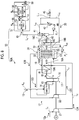
- FIG. 1A is a schematic view of a gas turbine cycle equipment related to Example 1.
- FIG. 1B is a schematic view illustrating an example of the temperature/pressure conditions of the gas turbine cycle equipment related to Example 1.
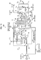
- the gas turbine cycle equipment 10A related to the present example includes a gas turbine 17 that has a combustor 14 that combusts fuel 13 with compressed air and a power turbine 16 that is driven by a high-temperature/high-pressure combustion gas 15 from the combustor 14, and an exhaust heat recovery device 19 that recovers heat energy from combustion flue gas 18 that has driven the power turbine 16.
- the compressed air 12 includes primary compressed air 12A that is compressed by a primary air compressor 21 that compresses air 12a, and secondary compressed air 12C that is compressed by a secondary air compressor 22 that further compresses the primary compressed air 12A.
- the exhaust heat recovery device 19 includes a first heat exchange unit 19A that performs indirect heat exchange between the combustion flue gas 18 and the secondary compressed air 12C, and a second heat exchange unit 19B that passes through the first heat exchange unit 19A, performs indirect heat exchange between combustion flue gas 18A after first heat exchange and the primary compressed air 12A and the supply water 30 in an saturator 31, and entrain steam 38 in the primary compressed air 12A.
- the primary compressed air 12B which entrains the steam that has been subjected to heat exchange in the saturator 31 of the second heat exchange unit 19B, is introduced into the secondary air compressor 22, thereby producing high-pressure secondary compressed air (low temperature) 12C, then heat exchange of the high-pressure secondary compressed air (low temperature) 12C in the first heat exchange unit 19A is performed, thereby producing high-pressure secondary compressed air (high temperature) 12D, and then, the high-pressure secondary compressed air (high temperature) 12D is introduced into the combustor 14 as compressed air for combustion.
- a third heat exchange unit 19C that performs heat exchange of the supply water 30, using the combustion flue gas 18B after being subjected to heat exchange in the second heat exchange unit 19B, is further provided on a downstream side of the second heat exchange unit 19B of the exhaust heat recovery device 19.
- a cooling line L 10 including a cooling tower 41 that cools the flue gas 40 after heat exchange discharged from the exhaust heat recovery device 19, and a cooler 42 that circulates the cooling tower 41 with a pump P1, and a supply water supply line L 11 along which condensed water 44 condensed within the cooling tower 41 is supplied as the supply water 30 to the saturator 31.
- reference sign 45 represents discharge water
- 46 represents a chimney
- G represents a power generator that is coupled to the power turbine 16 and generates power
- L 1 represents an air introduction line
- L 2 represents a primary compressed air supply line
- L 3 represents a secondary compressed air supply line
- L 4 represents a fuel supply line
- L 5 represents a combustion gas supply line
- L 6 represents a combustion flue gas discharge line
- L 7 represents a flue gas line
- L 8 represents a flue gas discharge line along which the flue gas 40 is to be discharged to the chimney 46
- L 12 represents a wastewater line.
- the gas turbine 17 includes the primary and secondary air compressors 21 and 22, the combustor 14, and the power turbine 16.
- the air 12a introduced from the outside is compressed in the primary and secondary air compressors 21 and 22, and the compressed air 12 made to have high temperature/high pressure is guided to the combustor 14 side.
- the high-temperature/high-pressure compressed air 12, and the fuel 13 are injected and combusted, and a high-temperature (for example, 1500°C) combustion gas 15 is generated.
- the combustion gas 15 is injected into the power turbine 16, and the heat energy of the high-temperature high-pressure combustion gas 15 is converted into rotational energy in the power turbine 16.
- the coaxial primary/secondary air compressors 21 and 22 are driven with this rotational energy, and the power generator G is driven with the rotational energy remaining after being used to drive this compressor, and generates power.
- the combustion flue gas 18 that has driven the power turbine 16 is guided to the exhaust heat recovery device 19 in order to recover the heat energy thereof.
- This exhaust heat recovery device 19 includes the first heat exchange unit 19A and the second heat exchange unit 19B.
- the secondary compressed air (a low temperature of 275°C and a pressure of 21 ata (2.1 MPa)) 12C is subjected to heat exchanged using the high-temperature (for example, 617°C) combustion flue gas 18 discharged from the power turbine 16.
- the primary compressed air (a temperature of 224°C and a pressure of 6 ata (0.6 MPa)) 12A is introduced into the saturator 31 and is subjected to heat exchange.
- FIG. 2 is an enlarged view of main parts of FIG. 1 .
- FIG. 3 is a perspective view of the heat exchange tube, and FIGS. 4 and 5 are schematic sectional views of the heat exchange tube.
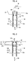
- the saturator 31 includes a supply water header 32 that introduces the supply water 30 condensed in the cooling tower 41 thereinto, a plurality of heat exchange tubes 33 that communicate with the supply water header 32 on one end 33a side and are arranged within the exhaust heat recovery device 19, a storage header 37 that communicates with the heat exchange tubes 33 on the other end 33b side, stores the supply water 30 within a storage part 34, and has an introducing part 36 that introduces the primary compressed air 12A into a space 35 on an upper side of the storage part 34, and a supply water circulation line L 20 along which the supply water 30 is circulated with a pump P 2 .
- FIGS. 4 and 5 are views illustrating an aspect in which supply water is supplied to each heat exchange tube 33 within the supply water header 32.
- a supply nozzle 39 provided in the supply water header 32 is used for the supply of the supply water 30, and the supply water 30 sprayed from the supply nozzle 39 is dropped while forming a water screen 30a in the shape of a wet wall along a wall surface 33d within the heat exchange tube 33.
- the supply water 30 is made to overflow from the storage part 32a of the supply water header 32 as the supply of the supply water 30, and the overflowed supply water 30 is dropped while forming the water screen 30a in the shape of a wet wall along the wall surface 33d within the heat exchange tube 33.
- the primary compressed air 12A is passed from a lower side into a tube space 33c for the supply water 30 dropped and circulated by the water screen 30a along the wall surface 33d of each of the plurality of heat exchange tube 33. Then, when the primary compressed air 12A passes, the primary compressed air is subjected to heat exchange with the combustion flue gas 18A that abuts against an outer periphery of each heat exchange tube 33. In the case of this heat exchange, the steam 38 is generated while heating the supply water 30 that flows down, this generated steam 38 is entrained in the primary compressed air 12A subjected to heat exchange, and is created as the primary compressed air (water steam) 12B.
- the supply water 30 is injected by the supply nozzle 39 and IS made to flow into the heat exchange tube 33.
- the supply water 30 that has flowed into the heat exchange tube 33 is dropped while forming the water screen 30a in the shape of a wet wall along the wall surface 33d of the heat exchange tube 33, and is stored on the storage header 37 on the downstream side.
- the stored supply water 30 is again circulated through the supply water header 32 by the supply water circulation line L 20 via the pump P 2 .
- the wet wall-like water screen 30a that flows through the inside of the heat exchange tube 33 is indirectly heated by the heat of the combustion flue gas 18A from the outside, and the supply water 30 becomes the steam 38 by heat exchange, is entrained in the primary compressed air 12A, and becomes the primary compressed air (water steam) 12B.
- the second heat exchange unit 19B performs heat exchange using the combustion flue gas 18A that has contributed to the heat exchange in the first heat exchange unit 19A.
- the primary compressed air (a pressure of 6 ata (0.6 MPa)) 12A introduced into the space 35 within the storage header 37 of the saturator 31 is cooled by the supply water 30 to be introduced, and the temperature thereof falls from 224°C to 84°C within the space 35.
- the primary compressed air 12A made to have this low temperature (84°C) is indirectly subjected to heat exchange with the combustion flue gas 18A after the first heat exchange, in the saturator 31 of the second heat exchange unit 19B, and becomes the primary compressed air (water steam) 12B of which the temperature reaches 107°C (a pressure of 6 ata).
- the primary compressed air (water steam) 12B is introduced into the secondary air compressor 22, is subjected to second compression, and becomes the high-pressure (a pressure of 21 ata (2.1 MPa)) secondary compressed air (low temperature: 275°C) 12C.
- the secondary compressed air 12C is low (275°C) in temperature, is capable of being subjected to heat exchange with the high-temperature (for example, 617°C) combustion flue gas 18 in the first heat exchange unit 19A of the exhaust heat recovery device 19, and becomes the high-pressure secondary compressed air (a high temperature of 565°C) 12D.
- the primary compressed air (a temperature of 224°C) compressed by the primary air compressor is introduced into the same secondary air compressor as it is, and is introduced into the combustor as high-pressure (21 ata)/high-temperature (400°C) compressed air.
- a total amount of the low-pressure (a pressure of 6 ata) primary compressed air 12A, which has passed through the primary air compressor 21 is introduced into the second heat exchange unit 19B of the exhaust heat recovery device 19, is subjected to heat exchange with the combustion flue gas 18A after being subjected to heat exchange in the first heat exchange unit 19A, in the saturator 31.
- the supply water 30 is introduced so as to lower (275°C ⁇ 84°C) the temperature of the low-pressure (a pressure of 6 ata) primary compressed air 12A, is subjected to heat exchange with the exhaust heat of the combustion flue gas (a temperature of 336°C) 18A after being subjected to heat exchange in the first heat exchange unit 19A, and becomes the low-pressure primary compressed air (water steam) 12B of which the temperature has been raised (107°C).
- the primary compressed air (water steam) (107°C) 12B is further compressed by the secondary air compressor 22 next, and becomes the high-pressure (a pressure of 21 ata) secondary compressed air (low temperature: 275°C) 12C.
- this secondary compression the capacity of the compressor can be made small because the temperature falls unlike a case where compression is continuous as in the related art.
- the high-pressure secondary compressed air (low temperature: 275°C) 12C is introduced into the first heat exchange unit 19A of the exhaust heat recovery device 19, becomes the high-pressure secondary compressed air (high temperature: 565°C) 12D, and is introduced into the combustor 14.
- the amount of the steam 38 to be entrained is small in the case of the heat exchange of the primary compressed air 12A in the second heat exchange unit 19B, it is possible to raise combustion temperature in the combustor 14 to a high temperature of, for example, 1500°C.
- the third heat exchange unit 19C is installed, and performs heat exchange so as to further improve the exhaust heat recovery efficiency of the combustion flue gas 18 when condensed water that has condensed moisture in the combustion flue gas 18C in the cooling tower 41 is supplied to the saturator 31 as the supply water 30. That is, since the temperature of the supply water 30 that is cooled and condensed in the cooling tower 41 is about 40°C, the supply water 30 at 40°C is passed through the third heat exchange unit 19C, is subjected to heat exchange with the combustion flue gas (120°C) 18B, and is supplied to the storage header 37 side as the supply water 30 at a temperature of 88°C.
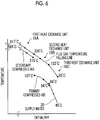
- FIG. 6 is a relationship view between temperature and enthalpy in a temperature falling line of an combustion flue gas and in a rising line of supply water temperature and compressed air.
- the temperature of the combustion flue gas 18 falls gradually (the first heat exchange unit 19A (617°C ⁇ 336°C), the second heat exchange unit 19B (336°C ⁇ 120°C), and the third heat exchange unit 19C (120°C ⁇ 95°C)) in the first heat exchange unit 19A, the second heat exchange unit 19B, and the third heat exchange unit 19C.
- the supply water 30 rises from 40°C to 88°C in the third heat exchange unit 19C, and rises from 84°C to 107°C because the temperature of the primary compressed air 12A falls in the saturator 31.
- the secondary compressed air 12C rises from 275°C to 565°C in the first heat exchange unit 19A.
- gas turbine cycle efficiency reaches 66.76% (LHV base) depending on a relationship between input heat and exhaust loss. This made it possible to achieve a significant improvement of about 6.7% or more greater than 60% that is the gas turbine cycle efficiency of a related-art 1500°C class.
- the exhaust heat recovery device 19 of the present example when exhaust heat is recovered by performing heat exchange of the combustion flue gas 18, in the exhaust heat recovery device 19 of the present example, efficient heat exchange is performed in the first heat exchange unit 19A, the second heat exchange unit 19B, and the third heat exchange unit 19C, respectively.
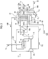
- the third heat exchange unit 19C may be omitted as illustrated in the gas turbine cycle equipment 10B illustrated in FIG. 7 .
- FIG. 8 is a schematic view of the equipment for recovering CO 2 from flue gas related to Example 2.
- the equipment 50 for recovering CO 2 from flue gas related to the present example includes the gas turbine cycle equipment 10A of Example 1, and a CO 2 recovery unit 51 that recovers CO 2 in the flue gas 40 from which the moisture from the cooling tower 41 has been removed.
- the CO 2 recovery unit 51 includes a CO 2 absorption tower 53 that remove CO 2 in the flue gas 40 after cooling in the cooling tower 41, using an absorbing liquid 52, and an absorbing liquid regeneration tower 54 that regenerates the absorbing liquid 52.
- the CO 2 recovery unit 51 makes the amine absorbing liquid to absorb and remove CO 2 contained in the flue gas 40 within the CO 2 absorption tower 53, and discharges the removed CO 2 as a treated flue gas 55 from a top side of the CO 2 absorption tower 53.
- the absorbing liquid 52 that has absorbed CO 2 is regenerated by steam stripping using a reboiler 59, in the absorbing liquid regeneration tower 54, and forms closed-system circulation lines L 21 and L 22 to be again reused in the CO 2 absorption tower 53.
- the amine-based absorbing liquid is, for example, brought into opposed contact with the flue gas 40 so as to take CO 2 into the amine absorbing liquid.
- the gas 56 containing CO 2 removed by the steam stripping is discharged, moisture is removed by a gas-liquid separator, and CO 2 is recovered as gas.
- a cooling tower is separately provided on a preceding stage side of the CO 2 recovery unit so as to cool the flue gas.
- the flue gas 40 is cooled by the cooling tower 41 for obtaining the supply water 30.
- CO 2 concentration in flue gas is as low as 3.5 to 4.0 Vol.%.
- CO 2 concentration in flue gas rises as high as 5 to 7 Vol.%. As a result, the amount of the flue gas can be reduced, and the CO 2 recovery unit can be made compact.
- the CO 2 recovery unit 51 a case including the CO 2 absorption tower 53 that absorbs CO 2 in the flue gas 40 with the absorbing liquid 52, and the absorbing liquid regeneration tower 54 that regenerates the absorbing liquid 52 that has absorbed CO 2 has been described as the CO 2 recovery unit 51.
- the present invention is not limited to this. Arbitrary equipment may be used as long as the equipment can recover CO 2 in flue gas.
Landscapes
- Engineering & Computer Science (AREA)
- Chemical & Material Sciences (AREA)
- Combustion & Propulsion (AREA)
- Mechanical Engineering (AREA)
- General Engineering & Computer Science (AREA)
- General Chemical & Material Sciences (AREA)
- Analytical Chemistry (AREA)
- Oil, Petroleum & Natural Gas (AREA)
- Chemical Kinetics & Catalysis (AREA)
- Life Sciences & Earth Sciences (AREA)
- Sustainable Development (AREA)
- Sustainable Energy (AREA)
- Physics & Mathematics (AREA)
- Thermal Sciences (AREA)
- Treating Waste Gases (AREA)
Abstract

Description
- The present invention relates to gas turbine cycle equipment, equipment for recovering CO2 from flue gas, and a method for recovering exhaust heat from combustion flue gas that improve cycle efficiency.
- For example, in order to improve gas turbine (G/T) combined cycle efficiency, a heat recovery steam generator for effectively utilizing combustion flue gas from a gas turbine is used. This heat recovery steam generator (HRSG) is an apparatus that generates steam using a high-temperature combustion flue gas discharged from an exhaust heat generation source, such as a gas turbine, and is widely used in, for example, a gas turbine combined cycle (GTCC) power generation plant that supplies steam generated in the heat recovery steam generator to a steam turbine (S/T) and drives a power generator (PTLs 1 and 2).
-
- [PTL 1] Japanese Unexamined Patent Application Publication No.
2003-83003 - [PTL 2] Japanese Unexamined Patent Application Publication No.
2013-171001 - However, in the related-art heat recovery steam generator, the heat recovery from a high-temperature combustion flue gas is performed at a temperature below a critical pressure using a plurality of stages, for example, high-pressure/medium-pressure/low-pressure individual economizers, an evaporator, a superheater, a reheater, and the like. Thus, heat exchange is performed so as not to reach a temperature falling line and a pinch point of the combustion flue gas. Additionally, there is a problem that reheating in the reheater is also only reheating at a temperature of about 600°C.
- Hence, even in a case where a gas turbine inlet temperature is a high pressure/high temperature of, for example, 1500°C class, the gas turbine efficiency (% LHV) is about 60%. In addition, in a case where the gas turbine inlet temperature is raised to, for example, 1700°C, there is a problem that there are various barriers against a turbine cooling technique, a heat shield coating technique, a heat-resisting material technique, and the like.
- Hence, even in gas turbine equipment in which the inlet temperature is, for example, 1500°C class, the appearance of a system that improves system efficiency is desired.
- An object of the invention is to provide gas turbine cycle equipment, equipment for recovering CO2 from flue gas, and a method for recovering exhaust heat from combustion flue gas that can improve gas turbine cycle efficiency in view of the above problems.
- A first invention of the present invention for solving the above problems provides gas turbine cycle equipment including a gas turbine having a combustor that combusts fuel with compressed air and a power turbine that is driven by a high-temperature/high-pressure combustion gas from the combustor; and an exhaust heat recovery device that recovers heat energy from combustion flue gas that has driven the power turbine. The compressed air includes primary compressed air that is compressed by a primary air compressor that compresses air, and secondary compressed air that is compressed by a secondary air compressor that further compresses the primary compressed air. The exhaust heat recovery device includes a first heat exchange unit that performs indirect heat exchange between the combustion flue gas and the secondary compressed air, and a second heat exchange unit that passes through the first heat exchange unit, performs indirect heat exchange between combustion flue gas after first heat exchange, and the primary compressed air and supply water, in a saturator, and entrains steam in the primary compressed air. The primary compressed air, which entrains the steam that has performed heat exchange in the saturator of the second heat exchange unit, is introduced into the secondary air compressor, thereby producing high-pressure/low-temperature secondary compressed air, then heat exchange of the high-pressure/low-temperature secondary compressed air is performed in the first heat exchange unit, thereby producing high-pressure high-temperature secondary compressed air, and then, the high-pressure high-temperature secondary compressed air is introduced into the combustor.
- A second invention is the gas turbine cycle equipment according to the first invention in which the saturator of the second heat exchange unit includes a supply water header that introduces the supply water thereinto, a plurality of heat exchange tubes that communicate with the supply water header at one end and are arranged within the exhaust heat recovery device, a storage header that communicates with the heat exchange tubes at the other end, stores the supply water, and has an introducing part that introduces the primary compressed air into a space of a storage part, and a supply water circulation line along which the supply water is circulated. The primary compressed air is passed through tube spaces for supply water that circulates in the shape of a wet wall along inner wall surfaces of the heat exchange tubes, the primary compressed air is subjected to heat exchange with the combustion flue gas that abuts against outer peripheries of the heat exchange tubes, steam is generated while heating the supply water, and the generated steam is entrained in the primary compressed air subjected to the heat exchange.
- A third invention is the gas turbine cycle equipment according to the first or second invention, further including a cooling tower that cools a flue gas after heat exchange discharged from the exhaust heat recovery device; and a supply water supply line along which condensed water is supplied as the supply water to a supply water circulation line along which supply water circulates through the saturator.
- A fourth invention is the gas turbine cycle equipment according to any one invention of the first to third inventions in which the exhaust heat recovery device further includes a third heat exchange unit that performs indirect heat exchange between the combustion flue gas after passing through the second heat exchange unit, and the supply water in the supply water supply line.
- A fifth invention is equipment for recovering CO2 from flue gas including the gas turbine cycle equipment according to any one invention of the first to fourth inventions; and a CO2 recovery unit that recovers CO2 in flue gas from the cooling tower.
- A sixth invention is the equipment for recovering CO2 from flue gas according to the fifth invention in which the CO2 recovery unit includes a CO2 absorption tower that absorbs CO2 in flue gas with an absorbing liquid, and an absorbing liquid regeneration tower that regenerates the absorbing liquid which has absorbed CO2, and the absorbing liquid is circulated and reused.
- A seventh invention is a method for recovering exhaust heat from combustion flue gas. The method includes using the gas turbine cycle equipment according to the first invention, and subjecting the combustion flue gas from the gas turbine to heat exchange with high-pressure secondary compressed air in the first heat exchange unit of the exhaust heat recovery device, performing heat recovery of low-pressure primary compressed air, using the heat-exchanged flue gas, in the second heat exchange unit of the saturator, introducing the primary compressed air, which has recovered the heat in the second heat exchange unit, into the secondary air compressor, thereby producing high-pressure primary compressed air, then recovering heat in the first heat exchange unit, thereby producing secondary compressed air, and introducing the secondary compressed air into the combustor to combust fuel using the secondary compressed air.
- According to the invention, by using the combustion flue gas from the gas turbine, the high-pressure secondary compressed air is subjected to the heat exchange in the first heat exchange unit of the exhaust heat recovery device, and by using the heat-exchanged flue gas, the low-pressure primary compressed air is subjected to the heat recovery in the second heat exchange unit of the saturator. Then, the primary compressed air that has recovered the heat in the second heat exchange unit is introduced into the secondary air compressor, thereby producing the high-pressure primary compressed air, and then the high-pressure primary compressed air is subjected to the heat recovery in the first heat exchange unit, producing the secondary compressed air. The secondary compressed air is introduced into the combustor and fuel is combusted using the secondary compressed air, and thereby, temperature is increased up to, for example, 1500°C. Accordingly, the exhaust heat recovery efficiency of the exhaust heat recovery device can be made very high. As a result, the gas turbine cycle efficiency can be improved.
-
-
FIG. 1A is a schematic view of a gas turbine cycle equipment related to Example 1. -
FIG. 1B is a schematic view illustrating an example of the temperature/pressure conditions of the gas turbine cycle equipment related to Example 1. -
FIG. 2 is an enlarged view of main parts of the gas turbine cycle equipment related to Example 1. -
FIG. 3 is a perspective view of a heat exchange tube. -
FIG. 4 is a schematic sectional view of the heat exchange tube. -
FIG. 5 is a schematic sectional view of the heat exchange tube. -
FIG. 6 is a relationship view between temperature and enthalpy in a temperature falling line of combustion flue gas and in a rising line of supply water temperature and compressed air. -
FIG. 7 is a schematic view of another gas turbine cycle equipment of Example 1. -
FIG. 8 is a schematic view of equipment for recovering CO2 from flue gas related to Example 2. Description of Embodiments - Preferable examples of the invention will be described below in detail with reference to the accompanying drawings. In addition, the invention is not limited by the examples and includes those configured by combining respective examples in a case where there are a plurality of examples.
-
FIG. 1A is a schematic view of a gas turbine cycle equipment related to Example 1.FIG. 1B is a schematic view illustrating an example of the temperature/pressure conditions of the gas turbine cycle equipment related to Example 1. - As illustrated in
FIG. 1A , the gasturbine cycle equipment 10A related to the present example includes agas turbine 17 that has acombustor 14 that combustsfuel 13 with compressed air and apower turbine 16 that is driven by a high-temperature/high-pressure combustion gas 15 from thecombustor 14, and an exhaustheat recovery device 19 that recovers heat energy fromcombustion flue gas 18 that has driven thepower turbine 16. The compressed air 12 includes primary compressedair 12A that is compressed by aprimary air compressor 21 that compressesair 12a, and secondary compressedair 12C that is compressed by asecondary air compressor 22 that further compresses the primarycompressed air 12A. The exhaustheat recovery device 19 includes a firstheat exchange unit 19A that performs indirect heat exchange between thecombustion flue gas 18 and the secondary compressedair 12C, and a secondheat exchange unit 19B that passes through the firstheat exchange unit 19A, performs indirect heat exchange betweencombustion flue gas 18A after first heat exchange and the primary compressedair 12A and thesupply water 30 in ansaturator 31, and entrainsteam 38 in the primary compressedair 12A. The primary compressedair 12B, which entrains the steam that has been subjected to heat exchange in thesaturator 31 of the secondheat exchange unit 19B, is introduced into thesecondary air compressor 22, thereby producing high-pressure secondary compressed air (low temperature) 12C, then heat exchange of the high-pressure secondary compressed air (low temperature) 12C in the firstheat exchange unit 19A is performed, thereby producing high-pressure secondary compressed air (high temperature) 12D, and then, the high-pressure secondary compressed air (high temperature) 12D is introduced into thecombustor 14 as compressed air for combustion. - In the present example, a third
heat exchange unit 19C that performs heat exchange of thesupply water 30, using thecombustion flue gas 18B after being subjected to heat exchange in the secondheat exchange unit 19B, is further provided on a downstream side of the secondheat exchange unit 19B of the exhaustheat recovery device 19. - Additionally, in the present example, a cooling line L10 including a
cooling tower 41 that cools theflue gas 40 after heat exchange discharged from the exhaustheat recovery device 19, and acooler 42 that circulates thecooling tower 41 with a pump P1, and a supply water supply line L11 along which condensedwater 44 condensed within thecooling tower 41 is supplied as thesupply water 30 to thesaturator 31. - In addition, in
FIGS. 1A and1B ,reference sign 45 represents discharge water, 46 represents a chimney, G represents a power generator that is coupled to thepower turbine 16 and generates power, L1 represents an air introduction line, L2 represents a primary compressed air supply line, L3 represents a secondary compressed air supply line, L4 represents a fuel supply line, L5 represents a combustion gas supply line, L6 represents a combustion flue gas discharge line, L7 represents a flue gas line, L8 represents a flue gas discharge line along which theflue gas 40 is to be discharged to thechimney 46, and L12 represents a wastewater line. - The
gas turbine 17 includes the primary andsecondary air compressors combustor 14, and thepower turbine 16. Theair 12a introduced from the outside is compressed in the primary andsecondary air compressors combustor 14 side. In thecombustor 14, the high-temperature/high-pressure compressed air 12, and thefuel 13 are injected and combusted, and a high-temperature (for example, 1500°C)combustion gas 15 is generated. Thecombustion gas 15 is injected into thepower turbine 16, and the heat energy of the high-temperature high-pressure combustion gas 15 is converted into rotational energy in thepower turbine 16. The coaxial primary/secondary air compressors - Next, the
combustion flue gas 18 that has driven thepower turbine 16 is guided to the exhaustheat recovery device 19 in order to recover the heat energy thereof. - This exhaust
heat recovery device 19 includes the firstheat exchange unit 19A and the secondheat exchange unit 19B. In the firstheat exchange unit 19A, as illustrated inFIG. 1B , the secondary compressed air (a low temperature of 275°C and a pressure of 21 ata (2.1 MPa)) 12C is subjected to heat exchanged using the high-temperature (for example, 617°C)combustion flue gas 18 discharged from thepower turbine 16. Additionally, in the secondheat exchange unit 19B on the downstream side of the firstheat exchange unit 19A, the primary compressed air (a temperature of 224°C and a pressure of 6 ata (0.6 MPa)) 12A is introduced into thesaturator 31 and is subjected to heat exchange. -
FIG. 2 is an enlarged view of main parts ofFIG. 1 .FIG. 3 is a perspective view of the heat exchange tube, andFIGS. 4 and 5 are schematic sectional views of the heat exchange tube. - As illustrated in
FIG. 2 , thesaturator 31 includes asupply water header 32 that introduces thesupply water 30 condensed in thecooling tower 41 thereinto, a plurality ofheat exchange tubes 33 that communicate with thesupply water header 32 on oneend 33a side and are arranged within the exhaustheat recovery device 19, astorage header 37 that communicates with theheat exchange tubes 33 on the other end 33b side, stores thesupply water 30 within astorage part 34, and has an introducingpart 36 that introduces the primarycompressed air 12A into aspace 35 on an upper side of thestorage part 34, and a supply water circulation line L20 along which thesupply water 30 is circulated with a pump P2. -
FIGS. 4 and 5 are views illustrating an aspect in which supply water is supplied to eachheat exchange tube 33 within thesupply water header 32. - Referring to
FIG. 4 , asupply nozzle 39 provided in thesupply water header 32 is used for the supply of thesupply water 30, and thesupply water 30 sprayed from thesupply nozzle 39 is dropped while forming awater screen 30a in the shape of a wet wall along awall surface 33d within theheat exchange tube 33. - Referring to
FIG. 5 , thesupply water 30 is made to overflow from the storage part 32a of thesupply water header 32 as the supply of thesupply water 30, and the overflowedsupply water 30 is dropped while forming thewater screen 30a in the shape of a wet wall along thewall surface 33d within theheat exchange tube 33. - Then, as illustrated in
FIGS. 3 ,4, and 5 , the primarycompressed air 12A is passed from a lower side into atube space 33c for thesupply water 30 dropped and circulated by thewater screen 30a along thewall surface 33d of each of the plurality ofheat exchange tube 33. Then, when the primarycompressed air 12A passes, the primary compressed air is subjected to heat exchange with thecombustion flue gas 18A that abuts against an outer periphery of eachheat exchange tube 33. In the case of this heat exchange, thesteam 38 is generated while heating thesupply water 30 that flows down, this generatedsteam 38 is entrained in the primarycompressed air 12A subjected to heat exchange, and is created as the primary compressed air (water steam) 12B. - Then, for example, as illustrated in
FIG. 4 , thesupply water 30 is injected by thesupply nozzle 39 and IS made to flow into theheat exchange tube 33. Thesupply water 30 that has flowed into theheat exchange tube 33 is dropped while forming thewater screen 30a in the shape of a wet wall along thewall surface 33d of theheat exchange tube 33, and is stored on thestorage header 37 on the downstream side. The storedsupply water 30 is again circulated through thesupply water header 32 by the supply water circulation line L20 via the pump P2. - Then, the wet wall-
like water screen 30a that flows through the inside of theheat exchange tube 33 is indirectly heated by the heat of thecombustion flue gas 18A from the outside, and thesupply water 30 becomes thesteam 38 by heat exchange, is entrained in the primarycompressed air 12A, and becomes the primary compressed air (water steam) 12B. The secondheat exchange unit 19B performs heat exchange using thecombustion flue gas 18A that has contributed to the heat exchange in the firstheat exchange unit 19A. - Here, the primary compressed air (a pressure of 6 ata (0.6 MPa)) 12A introduced into the
space 35 within thestorage header 37 of thesaturator 31 is cooled by thesupply water 30 to be introduced, and the temperature thereof falls from 224°C to 84°C within thespace 35. - The primary
compressed air 12A made to have this low temperature (84°C) is indirectly subjected to heat exchange with thecombustion flue gas 18A after the first heat exchange, in thesaturator 31 of the secondheat exchange unit 19B, and becomes the primary compressed air (water steam) 12B of which the temperature reaches 107°C (a pressure of 6 ata). - Next, the primary compressed air (water steam) 12B is introduced into the
secondary air compressor 22, is subjected to second compression, and becomes the high-pressure (a pressure of 21 ata (2.1 MPa)) secondary compressed air (low temperature: 275°C) 12C. - The secondary
compressed air 12C is low (275°C) in temperature, is capable of being subjected to heat exchange with the high-temperature (for example, 617°C)combustion flue gas 18 in the firstheat exchange unit 19A of the exhaustheat recovery device 19, and becomes the high-pressure secondary compressed air (a high temperature of 565°C) 12D. - In the related art, in a case where one compressor is installed to perform compressing, the primary compressed air (a temperature of 224°C) compressed by the primary air compressor is introduced into the same secondary air compressor as it is, and is introduced into the combustor as high-pressure (21 ata)/high-temperature (400°C) compressed air.
- In contrast, in the present invention, a total amount of the low-pressure (a pressure of 6 ata) primary
compressed air 12A, which has passed through theprimary air compressor 21 is introduced into the secondheat exchange unit 19B of the exhaustheat recovery device 19, is subjected to heat exchange with thecombustion flue gas 18A after being subjected to heat exchange in the firstheat exchange unit 19A, in thesaturator 31. - In this case, in the
saturator 31, thesupply water 30 is introduced so as to lower (275°C → 84°C) the temperature of the low-pressure (a pressure of 6 ata) primarycompressed air 12A, is subjected to heat exchange with the exhaust heat of the combustion flue gas (a temperature of 336°C) 18A after being subjected to heat exchange in the firstheat exchange unit 19A, and becomes the low-pressure primary compressed air (water steam) 12B of which the temperature has been raised (107°C). The primary compressed air (water steam) (107°C) 12B is further compressed by thesecondary air compressor 22 next, and becomes the high-pressure (a pressure of 21 ata) secondary compressed air (low temperature: 275°C) 12C. In the case of this secondary compression, the capacity of the compressor can be made small because the temperature falls unlike a case where compression is continuous as in the related art. - Moreover, the high-pressure secondary compressed air (low temperature: 275°C) 12C is introduced into the first
heat exchange unit 19A of the exhaustheat recovery device 19, becomes the high-pressure secondary compressed air (high temperature: 565°C) 12D, and is introduced into thecombustor 14. - In the present example, since the amount of the
steam 38 to be entrained is small in the case of the heat exchange of the primarycompressed air 12A in the secondheat exchange unit 19B, it is possible to raise combustion temperature in thecombustor 14 to a high temperature of, for example, 1500°C. - Additionally, in the present example, the third
heat exchange unit 19C is installed, and performs heat exchange so as to further improve the exhaust heat recovery efficiency of thecombustion flue gas 18 when condensed water that has condensed moisture in thecombustion flue gas 18C in thecooling tower 41 is supplied to thesaturator 31 as thesupply water 30. That is, since the temperature of thesupply water 30 that is cooled and condensed in thecooling tower 41 is about 40°C, thesupply water 30 at 40°C is passed through the thirdheat exchange unit 19C, is subjected to heat exchange with the combustion flue gas (120°C) 18B, and is supplied to thestorage header 37 side as thesupply water 30 at a temperature of 88°C. - In this way, when exhaust heat is recovered by performing heat exchange of the
combustion flue gas 18, in the exhaustheat recovery device 19 of the present example, efficient heat exchange is performed in the firstheat exchange unit 19A, the secondheat exchange unit 19B, and the thirdheat exchange unit 19C, respectively. Thus, the heat of the high-temperature (617°C)combustion flue gas 18 is recovered to a low temperature (95°C), and the heat recovery efficiency improves. - Additionally, since the amount of the
steam 38 entrained in the primary compressed air (water steam) 12B is small, exhaust loss becomes little. -
FIG. 6 is a relationship view between temperature and enthalpy in a temperature falling line of an combustion flue gas and in a rising line of supply water temperature and compressed air. - As illustrated in
FIG. 6 , the temperature of thecombustion flue gas 18 falls gradually (the firstheat exchange unit 19A (617°C → 336°C), the secondheat exchange unit 19B (336°C → 120°C), and the thirdheat exchange unit 19C (120°C → 95°C)) in the firstheat exchange unit 19A, the secondheat exchange unit 19B, and the thirdheat exchange unit 19C. - In contrast, the
supply water 30 rises from 40°C to 88°C in the thirdheat exchange unit 19C, and rises from 84°C to 107°C because the temperature of the primarycompressed air 12A falls in thesaturator 31. Next, the secondarycompressed air 12C rises from 275°C to 565°C in the firstheat exchange unit 19A. - Additionally, as shown in Table 1, gas turbine cycle efficiency reaches 66.76% (LHV base) depending on a relationship between input heat and exhaust loss. This made it possible to achieve a significant improvement of about 6.7% or more greater than 60% that is the gas turbine cycle efficiency of a related-art 1500°C class.
[Table 1] 1. Input of Heat Air: 2,158T/Hx(1500-565°C)x0.285=575.05x106kcal/H Water: 378.0T/Hx(1500-565°C)x0.556=196.51x106kcal/H 
2. Flue Gas Loss Air: 2,158T/Hx(95-15°C)x0.24=41.43x106kcal/H Water: 378.0T/Hx(639.3-40.0°C)=226.5x106kcal/H 
3. Gas Turbine Efficiency 
- As described above, in a gas turbine combined cycle (GTCC) power generation plant including the related-art exhaust heat recovery steam generator using a high-pressure/medium-pressure/low-pressure boiler, the efficiency (LHV) thereof that is about 60% can be markedly raised.
- In the present example, when exhaust heat is recovered by performing heat exchange of the
combustion flue gas 18, in the exhaustheat recovery device 19 of the present example, efficient heat exchange is performed in the firstheat exchange unit 19A, the secondheat exchange unit 19B, and the thirdheat exchange unit 19C, respectively. However, the thirdheat exchange unit 19C may be omitted as illustrated in the gasturbine cycle equipment 10B illustrated inFIG. 7 . - In this case, heat of the high-temperature (617°C)
combustion flue gas 18 is recovered to a low temperature (120°C). As a result, the heat recovery efficiency becomes slightly lower than that of the gasturbine cycle equipment 10A ofFIG. 1 . However, the equipment can be simplified. - Next, equipment for recovering CO2 from flue gas related to Example 2 of the present invention will be described with reference to
FIG. 8. FIG. 8 is a schematic view of the equipment for recovering CO2 from flue gas related to Example 2. In addition, the same members as those of Example 1 will be designated by the same reference signs, and the description thereof will be omitted. Theequipment 50 for recovering CO2 from flue gas related to the present example includes the gasturbine cycle equipment 10A of Example 1, and a CO2 recovery unit 51 that recovers CO2 in theflue gas 40 from which the moisture from thecooling tower 41 has been removed. The CO2 recovery unit 51 includes a CO2 absorption tower 53 that remove CO2 in theflue gas 40 after cooling in thecooling tower 41, using an absorbingliquid 52, and an absorbingliquid regeneration tower 54 that regenerates the absorbingliquid 52. - Generally, in a case where an amine-based absorbing liquid, for example, is used as the absorbing
liquid 52, the CO2 recovery unit 51 makes the amine absorbing liquid to absorb and remove CO2 contained in theflue gas 40 within the CO2 absorption tower 53, and discharges the removed CO2 as a treatedflue gas 55 from a top side of the CO2 absorption tower 53. Additionally, the absorbingliquid 52 that has absorbed CO2 is regenerated by steam stripping using areboiler 59, in the absorbingliquid regeneration tower 54, and forms closed-system circulation lines L21 and L22 to be again reused in the CO2 absorption tower 53. In addition, within the CO2 absorption tower 53, the amine-based absorbing liquid is, for example, brought into opposed contact with theflue gas 40 so as to take CO2 into the amine absorbing liquid. Here, on the absorbingliquid regeneration tower 54 side, thegas 56 containing CO2 removed by the steam stripping is discharged, moisture is removed by a gas-liquid separator, and CO2 is recovered as gas. - In the related art, in a case where CO2 in flue gas is recovered, a cooling tower is separately provided on a preceding stage side of the CO2 recovery unit so as to cool the flue gas. However, in Example 1, the
flue gas 40 is cooled by thecooling tower 41 for obtaining thesupply water 30. Thus, it becomes unnecessary to separately install cooling equipment in theequipment 50 for recovering CO2 from flue gas in the present example. Additionally, in ordinary gas turbines, CO2 concentration in flue gas is as low as 3.5 to 4.0 Vol.%. However, in the present gas turbine cycle, CO2 concentration in flue gas rises as high as 5 to 7 Vol.%. As a result, the amount of the flue gas can be reduced, and the CO2 recovery unit can be made compact. - In addition, in the present example, a case including the CO2 absorption tower 53 that absorbs CO2 in the
flue gas 40 with the absorbingliquid 52, and the absorbingliquid regeneration tower 54 that regenerates the absorbingliquid 52 that has absorbed CO2 has been described as the CO2 recovery unit 51. However, the present invention is not limited to this. Arbitrary equipment may be used as long as the equipment can recover CO2 in flue gas. -
- 10A, 10B:
- GAS TURBINE CYCLE EQUIPMENT
- 12a:
- AIR
- 12:
- COMPRESSED AIR
- 12A:
- PRIMARY COMPRESSED AIR
- 12B:
- PRIMARY COMPRESSED AIR (WATER STEAM)
- 12C:
- SECONDARY COMPRESSED AIR (LOW TEMPERATURE)
- 12D:
- SECONDARY COMPRESSED AIR (HIGH TEMPERATURE)
- 13:
- FUEL
- 14:
- COMBUSTOR
- 15:
- COMBUSTION GAS
- 16:
- POWER TURBINE
- 17:
- GAS TURBINE
- 18, 18A to 18C:
- COMBUSTION FLUE GAS
- 19:
- EXHAUST HEAT RECOVERY DEVICE
- 19A:
- FIRST HEAT EXCHANGE UNIT
- 19B:
- SECOND HEAT EXCHANGE UNIT
- 19C:
- THIRD HEAT EXCHANGE UNIT
- 21:
- PRIMARY AIR COMPRESSOR
- 22:
- SECONDARY AIR COMPRESSOR
- 31:
- SATURATOR
- 32:
- SUPPLY WATER HEADER
- 33:
- HEAT EXCHANGE TUBE
- 34:
- STORAGE PART
- 35:
- SPACE
- 37:
- STORAGE HEADER
- 38:
- STEAM
- 40:
- FLUE GAS
- 50:
- EQUIPMENT FOR RECOVERING CO2 FROM FLUE GAS
- 51:
- CO2 RECOVERY UNIT
Claims (7)
- Gas turbine cycle equipment comprising:a gas turbine having a combustor that combusts fuel with compressed air and a power turbine that is driven by a high-temperature/high-pressure combustion gas from the combustor; andan exhaust heat recovery device that recovers heat energy from combustion flue gas that has driven the power turbine,wherein the compressed air includes primary compressed air that is compressed by a primary air compressor that compresses air, and secondary compressed air that is compressed by a secondary air compressor that further compresses the primary compressed air,
wherein the exhaust heat recovery device includes a first heat exchange unit that performs indirect heat exchange between the combustion flue gas and the secondary compressed air, and a second heat exchange unit that passes through the first heat exchange unit, performs indirect heat exchange between combustion flue gas after first heat exchange, and the primary compressed air and supply water, in a saturator, and entrains steam in the primary compressed air, and
wherein the primary compressed air, which entrains the steam that has performed heat exchange in the saturator of the second heat exchange unit, is introduced into the secondary air compressor, thereby producing high-pressure/low-temperature secondary compressed air, then heat exchange of the high-pressure/low-temperature secondary compressed air is performed in the first heat exchange unit, thereby producing high-pressure/high-temperature secondary compressed air, and then, the high-pressure/high-temperature secondary compressed air is introduced into the combustor. - The gas turbine cycle equipment according to Claim 1,
wherein the saturator of the second heat exchange unit includes
a supply water header that introduces the supply water thereinto,
a plurality of heat exchange tubes that communicate with the supply water header at one end and are arranged within the exhaust heat recovery device,
a storage header that communicates with the heat exchange tubes at the other end, stores the supply water, and has an introducing part that introduces the primary compressed air into a space of a storage part, and
a supply water circulation line along which the supply water is circulated,
wherein the primary compressed air is passed through tube spaces for supply water that circulates in the shape of a wet wall along inner wall surfaces of the heat exchange tubes, the primary compressed air is subjected to heat exchange with the combustion flue gas that abuts against outer peripheries of the heat exchange tubes, steam is generated while heating the supply water, and the generated steam is entrained in the primary compressed air subjected to the heat exchange. - The gas turbine cycle equipment according to Claim 1 or 2, further comprising:a cooling tower that cools a flue gas after heat exchange discharged from the exhaust heat recovery device; anda supply water supply line along which condensed water is supplied as the supply water to a supply water circulation line along which supply water circulates through the saturator.
- The gas turbine cycle equipment according to any one of Claims 1 to 3,
wherein the exhaust heat recovery device further includes a third heat exchange unit that performs indirect heat exchange between the combustion flue gas after passing through the second heat exchange unit, and the supply water in the supply water supply line. - Equipment for recovering CO2 from flue gas comprising:the gas turbine cycle equipment according to any one of Claims 1 to 4; anda CO2 recovery unit that recovers CO2 in flue gas from the cooling tower.
- The equipment for recovering CO2 from flue gas according to Claim 5,
wherein the CO2 recovery unit includes a CO2 absorption tower that absorbs CO2 in flue gas with an absorbing liquid, and an absorbing liquid regeneration tower that regenerates the absorbing liquid which has absorbed CO2, and the absorbing liquid is circulated and reused. - A method for recovering exhaust heat from combustion flue gas, the method comprising:using the gas turbine cycle equipment according to Claim 1, andsubjecting the combustion flue gas from the gas turbine to heat exchange with high-pressure secondary compressed air in the first heat exchange unit of the exhaust heat recovery device, performing heat recovery of low-pressure primary compressed air, using the heat-exchanged flue gas, in the second heat exchange unit of the saturator, introducing the primary compressed air, which has recovered the heat in the second heat exchange unit, into the secondary air compressor, thereby producing high-pressure primary compressed air, then recovering heat in the first heat exchange unit, thereby producing secondary compressed air, and introducing the secondary compressed air into the combustor to combust fuel using the secondary compressed air.
Applications Claiming Priority (2)
| Application Number | Priority Date | Filing Date | Title |
|---|---|---|---|
| JP2014101758A JP6327941B2 (en) | 2014-05-15 | 2014-05-15 | Gas turbine cycle equipment, CO2 recovery equipment for exhaust gas, and exhaust heat recovery method for combustion exhaust gas |
| PCT/JP2015/062473 WO2015174246A1 (en) | 2014-05-15 | 2015-04-24 | Gas turbine cycle equipment, equipment for recovering co2 from exhaust gas, and method for recovering exhaust heat from combustion exhaust gas |
Publications (3)
| Publication Number | Publication Date |
|---|---|
| EP3128151A1 true EP3128151A1 (en) | 2017-02-08 |
| EP3128151A4 EP3128151A4 (en) | 2017-04-26 |
| EP3128151B1 EP3128151B1 (en) | 2019-01-02 |
Family
ID=54479789
Family Applications (1)
| Application Number | Title | Priority Date | Filing Date |
|---|---|---|---|
| EP15792546.2A Active EP3128151B1 (en) | 2014-05-15 | 2015-04-24 | Gas turbine cycle equipment, equipment for recovering co2 from exhaust gas, and method for recovering exhaust heat from combustion exhaust gas |
Country Status (5)
| Country | Link |
|---|---|
| US (1) | US10480406B2 (en) |
| EP (1) | EP3128151B1 (en) |
| JP (1) | JP6327941B2 (en) |
| CA (1) | CA2947254C (en) |
| WO (1) | WO2015174246A1 (en) |
Cited By (1)
| Publication number | Priority date | Publication date | Assignee | Title |
|---|---|---|---|---|
| CZ307836B6 (en) * | 2018-01-17 | 2019-06-12 | Vysoká Škola Báňská-Technická Univerzita Ostrava | Equipment for generating electricity using media accumulation |
Families Citing this family (10)
| Publication number | Priority date | Publication date | Assignee | Title |
|---|---|---|---|---|
| GB2546723B (en) * | 2015-12-11 | 2021-06-02 | Hieta Tech Limited | Inverted brayton cycle heat engine |
| JP6796140B2 (en) * | 2016-10-19 | 2020-12-02 | 三菱重工業株式会社 | Carbon dioxide capture system, thermal power generation equipment, and carbon dioxide capture method |
| US20180216532A1 (en) * | 2017-01-31 | 2018-08-02 | General Electric Company | System and method for treating exhaust gas |
| JP2019190359A (en) * | 2018-04-24 | 2019-10-31 | 三菱重工エンジニアリング株式会社 | Plant and combustion exhaust gas treatment method |
| CN111664438B (en) * | 2019-03-07 | 2021-10-08 | 中石化广州工程有限公司 | Water curtain type periodical pollution discharge flash tank |
| JP7412102B2 (en) * | 2019-07-24 | 2024-01-12 | 三菱重工業株式会社 | gas turbine plant |
| US11326513B1 (en) * | 2020-10-30 | 2022-05-10 | Doosan Heavy Industries & Construction Co., Ltd. | Hybrid power generation equipment |
| DE102022115556A1 (en) * | 2022-06-22 | 2023-12-28 | MTU Aero Engines AG | Method for operating a turbomachine |
| CN115060070B (en) * | 2022-06-23 | 2024-03-15 | 北新建材(陕西)有限公司 | Temperature circulation control using system for heating cold water by utilizing waste heat of dryer |
| EP4310393A1 (en) * | 2022-07-20 | 2024-01-24 | TotalEnergies OneTech | Installation for producing electricity or mechanical power, comprising a combined cycle gas turbine, and co2 capture and water electrolysis units |
Family Cites Families (20)
| Publication number | Priority date | Publication date | Assignee | Title |
|---|---|---|---|---|
| CA1213737A (en) | 1981-12-10 | 1986-11-12 | Hiromi Nakamura | Regenerative gas turbine cycle |
| JPS58101227A (en) * | 1981-12-10 | 1983-06-16 | Mitsubishi Gas Chem Co Inc | Gas turbine cycle |
| DE4237665A1 (en) * | 1992-11-07 | 1994-05-11 | Asea Brown Boveri | Method for operating a combination system |
| JP4299313B2 (en) * | 1997-04-22 | 2009-07-22 | 株式会社日立製作所 | Gas turbine equipment |
| DE10001112A1 (en) * | 2000-01-13 | 2001-07-19 | Alstom Power Schweiz Ag Baden | Cooling air cooler for gas turbine unit, with water separator on cooling air side behind jet device in flow direction |
| US7096659B1 (en) * | 2000-01-21 | 2006-08-29 | Hitachi, Ltd. | Gas turbine electric power generation equipment and air humidifier |
| US6584776B2 (en) | 2000-03-20 | 2003-07-01 | Exxonmobil Chemical Patents Inc. | Method for generating power |
| JP2003049665A (en) * | 2001-08-03 | 2003-02-21 | Mitsui Eng & Shipbuild Co Ltd | Gas turbine cogeneration system |
| JP2003083003A (en) | 2001-09-13 | 2003-03-19 | Mitsubishi Heavy Ind Ltd | Method for operating gas turbine and gas turbine combined power generating plant |
| SE0301585D0 (en) * | 2003-05-30 | 2003-05-30 | Euroturbine Ab | Procedure for operating a gas turbine group |
| JP2006002622A (en) * | 2004-06-16 | 2006-01-05 | Mitsui Eng & Shipbuild Co Ltd | Gas turbine regenerator |
| EP1609958A1 (en) * | 2004-06-22 | 2005-12-28 | Siemens Aktiengesellschaft | Gasturbine with compressor and recuperator |
| JP5039651B2 (en) * | 2008-07-08 | 2012-10-03 | 三菱重工業株式会社 | Carbon dioxide recovery system in exhaust gas |
| WO2011076973A1 (en) * | 2009-12-22 | 2011-06-30 | Reijo Alander | Arrangement in a gas turbine process |
| DE102010013729A1 (en) | 2010-03-31 | 2011-10-06 | Siemens Aktiengesellschaft | Method and apparatus for separating carbon dioxide from an exhaust gas of a fossil-fired power plant |
| JP2013540229A (en) * | 2010-10-05 | 2013-10-31 | アルストム テクノロジー リミテッド | Combined cycle power plant with CO2 capture and method of operating the same |
| JP5747309B2 (en) * | 2011-07-29 | 2015-07-15 | 一般財団法人電力中央研究所 | CAES system and power plant having the same |
| JP5716922B2 (en) | 2012-02-22 | 2015-05-13 | 三菱日立パワーシステムズ株式会社 | Waste heat recovery boiler and combined power generation facility |
| JP5639609B2 (en) * | 2012-03-01 | 2014-12-10 | 三菱日立パワーシステムズ株式会社 | Gas turbine system using high humidity air |
| JP5555276B2 (en) * | 2012-04-05 | 2014-07-23 | 川崎重工業株式会社 | Gas turbine engine device equipped with Rankine cycle engine |
-
2014
- 2014-05-15 JP JP2014101758A patent/JP6327941B2/en active Active
-
2015
- 2015-04-24 US US15/307,183 patent/US10480406B2/en active Active
- 2015-04-24 EP EP15792546.2A patent/EP3128151B1/en active Active
- 2015-04-24 WO PCT/JP2015/062473 patent/WO2015174246A1/en not_active Ceased
- 2015-04-24 CA CA2947254A patent/CA2947254C/en active Active
Cited By (1)
| Publication number | Priority date | Publication date | Assignee | Title |
|---|---|---|---|---|
| CZ307836B6 (en) * | 2018-01-17 | 2019-06-12 | Vysoká Škola Báňská-Technická Univerzita Ostrava | Equipment for generating electricity using media accumulation |
Also Published As
| Publication number | Publication date |
|---|---|
| US20170114718A1 (en) | 2017-04-27 |
| JP6327941B2 (en) | 2018-05-23 |
| EP3128151A4 (en) | 2017-04-26 |
| JP2015218634A (en) | 2015-12-07 |
| CA2947254C (en) | 2018-10-23 |
| CA2947254A1 (en) | 2015-11-19 |
| US10480406B2 (en) | 2019-11-19 |
| EP3128151B1 (en) | 2019-01-02 |
| WO2015174246A1 (en) | 2015-11-19 |
Similar Documents
| Publication | Publication Date | Title |
|---|---|---|
| EP3128151B1 (en) | Gas turbine cycle equipment, equipment for recovering co2 from exhaust gas, and method for recovering exhaust heat from combustion exhaust gas | |
| JP7112378B2 (en) | Method and system for power generation with improved efficiency | |
| ES2794776T3 (en) | Systems and methods for energy production using nested CO2 cycles | |
| RU2315186C2 (en) | Low contamination thermal power station | |
| RU2456060C2 (en) | Absorbent recovery by compressed top flow bled for heating purposes | |
| CN102741508B (en) | With CO 2the electricity generating device of catching and the method running such electricity generating device | |
| US8726662B2 (en) | Carbon dioxide recovery method and carbon-dioxide-recovery-type steam power generation system | |
| US8252091B2 (en) | CO2 recovery from IGCC power plants | |
| KR101623309B1 (en) | Supercritical carbon dioxide powder plant | |
| US10072531B2 (en) | Hybrid power generation system using supercritical CO2 cycle | |
| EP2444141A1 (en) | Carbon dioxide recovery method and carbon- dioxide-recovery-type steam power generation system | |
| CN108136321A (en) | For CO2The method and apparatus of trapping | |
| CN101892878B (en) | Method and system for use with an integrated gasification combined cycle plant | |
| JP2013151937A (en) | Method of using external fluid for cooling high temperature component of gas turbine for process power plant | |
| CN108771950A (en) | A kind of carbon dioxide recycle electricity generation system and method being pressurized using chemical absorbing | |
| Hu et al. | A low energy consumption de-carbonization natural gas combined cycle power generation system based on LiBr/H2O absorption heat transformer | |
| CN115680809B (en) | Split-flow recompression pure oxygen combustion circulation system | |
| Verhaeghe et al. | Retrofitting an existing combined cycle gas turbine with post-combustion carbon capture: Assessment of solvent selection impact on performance | |
| Conversano et al. | Techno-economic assessment of novel vs. standard 5m piperazine CCS absorption processes for conventional and high-efficiency NGCC power plants | |
| JPH09264158A (en) | Gas turbine cycle | |
| JP2012161750A (en) | Co2 recovery method and co2 recovery apparatus | |
| CN210768960U (en) | Coal-fired power generation system with carbon capture device | |
| CN111102026B (en) | Cascade supercritical carbon dioxide power circulation system and method | |
| RU2211343C1 (en) | Method of and plant for recovery of heat in contact-type steam-gas plant | |
| Alruwaili et al. | Techno-economic assessment of a commercial natural gas combined cycle with a chemical absorption plant using lean vapor compression modification |
Legal Events
| Date | Code | Title | Description |
|---|---|---|---|
| STAA | Information on the status of an ep patent application or granted ep patent |
Free format text: STATUS: THE INTERNATIONAL PUBLICATION HAS BEEN MADE |
|
| PUAI | Public reference made under article 153(3) epc to a published international application that has entered the european phase |
Free format text: ORIGINAL CODE: 0009012 |
|
| STAA | Information on the status of an ep patent application or granted ep patent |
Free format text: STATUS: REQUEST FOR EXAMINATION WAS MADE |
|
| 17P | Request for examination filed |
Effective date: 20161020 |
|
| AK | Designated contracting states |
Kind code of ref document: A1 Designated state(s): AL AT BE BG CH CY CZ DE DK EE ES FI FR GB GR HR HU IE IS IT LI LT LU LV MC MK MT NL NO PL PT RO RS SE SI SK SM TR |
|
| AX | Request for extension of the european patent |
Extension state: BA ME |
|
| A4 | Supplementary search report drawn up and despatched |
Effective date: 20170329 |
|
| RIC1 | Information provided on ipc code assigned before grant |
Ipc: F02C 3/30 20060101AFI20170323BHEP Ipc: B01D 53/62 20060101ALI20170323BHEP Ipc: F01K 21/04 20060101ALI20170323BHEP Ipc: F02C 7/143 20060101ALI20170323BHEP Ipc: F02C 7/08 20060101ALI20170323BHEP |
|
| DAV | Request for validation of the european patent (deleted) | ||
| DAX | Request for extension of the european patent (deleted) | ||
| GRAP | Despatch of communication of intention to grant a patent |
Free format text: ORIGINAL CODE: EPIDOSNIGR1 |
|
| STAA | Information on the status of an ep patent application or granted ep patent |
Free format text: STATUS: GRANT OF PATENT IS INTENDED |
|
| INTG | Intention to grant announced |
Effective date: 20180724 |
|
| RAP1 | Party data changed (applicant data changed or rights of an application transferred) |
Owner name: MITSUBISHI HEAVY INDUSTRIES ENGINEERING, LTD. |
|
| GRAS | Grant fee paid |
Free format text: ORIGINAL CODE: EPIDOSNIGR3 |
|
| GRAA | (expected) grant |
Free format text: ORIGINAL CODE: 0009210 |
|
| STAA | Information on the status of an ep patent application or granted ep patent |
Free format text: STATUS: THE PATENT HAS BEEN GRANTED |
|
| AK | Designated contracting states |
Kind code of ref document: B1 Designated state(s): AL AT BE BG CH CY CZ DE DK EE ES FI FR GB GR HR HU IE IS IT LI LT LU LV MC MK MT NL NO PL PT RO RS SE SI SK SM TR |
|
| REG | Reference to a national code |
Ref country code: GB Ref legal event code: FG4D |
|
| REG | Reference to a national code |
Ref country code: CH Ref legal event code: EP Ref country code: AT Ref legal event code: REF Ref document number: 1084674 Country of ref document: AT Kind code of ref document: T Effective date: 20190115 |
|
| REG | Reference to a national code |
Ref country code: IE Ref legal event code: FG4D |
|
| REG | Reference to a national code |
Ref country code: DE Ref legal event code: R096 Ref document number: 602015022902 Country of ref document: DE |
|
| REG | Reference to a national code |
Ref country code: NL Ref legal event code: FP |
|
| REG | Reference to a national code |
Ref country code: NO Ref legal event code: T2 Effective date: 20190102 |
|
| REG | Reference to a national code |
Ref country code: LT Ref legal event code: MG4D |
|
| REG | Reference to a national code |
Ref country code: AT Ref legal event code: MK05 Ref document number: 1084674 Country of ref document: AT Kind code of ref document: T Effective date: 20190102 |
|
| PG25 | Lapsed in a contracting state [announced via postgrant information from national office to epo] |
Ref country code: FI Free format text: LAPSE BECAUSE OF FAILURE TO SUBMIT A TRANSLATION OF THE DESCRIPTION OR TO PAY THE FEE WITHIN THE PRESCRIBED TIME-LIMIT Effective date: 20190102 Ref country code: PT Free format text: LAPSE BECAUSE OF FAILURE TO SUBMIT A TRANSLATION OF THE DESCRIPTION OR TO PAY THE FEE WITHIN THE PRESCRIBED TIME-LIMIT Effective date: 20190502 Ref country code: SE Free format text: LAPSE BECAUSE OF FAILURE TO SUBMIT A TRANSLATION OF THE DESCRIPTION OR TO PAY THE FEE WITHIN THE PRESCRIBED TIME-LIMIT Effective date: 20190102 Ref country code: PL Free format text: LAPSE BECAUSE OF FAILURE TO SUBMIT A TRANSLATION OF THE DESCRIPTION OR TO PAY THE FEE WITHIN THE PRESCRIBED TIME-LIMIT Effective date: 20190102 Ref country code: LT Free format text: LAPSE BECAUSE OF FAILURE TO SUBMIT A TRANSLATION OF THE DESCRIPTION OR TO PAY THE FEE WITHIN THE PRESCRIBED TIME-LIMIT Effective date: 20190102 Ref country code: ES Free format text: LAPSE BECAUSE OF FAILURE TO SUBMIT A TRANSLATION OF THE DESCRIPTION OR TO PAY THE FEE WITHIN THE PRESCRIBED TIME-LIMIT Effective date: 20190102 |
|
| PG25 | Lapsed in a contracting state [announced via postgrant information from national office to epo] |
Ref country code: LV Free format text: LAPSE BECAUSE OF FAILURE TO SUBMIT A TRANSLATION OF THE DESCRIPTION OR TO PAY THE FEE WITHIN THE PRESCRIBED TIME-LIMIT Effective date: 20190102 Ref country code: HR Free format text: LAPSE BECAUSE OF FAILURE TO SUBMIT A TRANSLATION OF THE DESCRIPTION OR TO PAY THE FEE WITHIN THE PRESCRIBED TIME-LIMIT Effective date: 20190102 Ref country code: IS Free format text: LAPSE BECAUSE OF FAILURE TO SUBMIT A TRANSLATION OF THE DESCRIPTION OR TO PAY THE FEE WITHIN THE PRESCRIBED TIME-LIMIT Effective date: 20190502 Ref country code: GR Free format text: LAPSE BECAUSE OF FAILURE TO SUBMIT A TRANSLATION OF THE DESCRIPTION OR TO PAY THE FEE WITHIN THE PRESCRIBED TIME-LIMIT Effective date: 20190403 Ref country code: BG Free format text: LAPSE BECAUSE OF FAILURE TO SUBMIT A TRANSLATION OF THE DESCRIPTION OR TO PAY THE FEE WITHIN THE PRESCRIBED TIME-LIMIT Effective date: 20190402 Ref country code: RS Free format text: LAPSE BECAUSE OF FAILURE TO SUBMIT A TRANSLATION OF THE DESCRIPTION OR TO PAY THE FEE WITHIN THE PRESCRIBED TIME-LIMIT Effective date: 20190102 |
|
| REG | Reference to a national code |
Ref country code: DE Ref legal event code: R097 Ref document number: 602015022902 Country of ref document: DE |
|
| PG25 | Lapsed in a contracting state [announced via postgrant information from national office to epo] |
Ref country code: DK Free format text: LAPSE BECAUSE OF FAILURE TO SUBMIT A TRANSLATION OF THE DESCRIPTION OR TO PAY THE FEE WITHIN THE PRESCRIBED TIME-LIMIT Effective date: 20190102 Ref country code: AT Free format text: LAPSE BECAUSE OF FAILURE TO SUBMIT A TRANSLATION OF THE DESCRIPTION OR TO PAY THE FEE WITHIN THE PRESCRIBED TIME-LIMIT Effective date: 20190102 Ref country code: EE Free format text: LAPSE BECAUSE OF FAILURE TO SUBMIT A TRANSLATION OF THE DESCRIPTION OR TO PAY THE FEE WITHIN THE PRESCRIBED TIME-LIMIT Effective date: 20190102 Ref country code: RO Free format text: LAPSE BECAUSE OF FAILURE TO SUBMIT A TRANSLATION OF THE DESCRIPTION OR TO PAY THE FEE WITHIN THE PRESCRIBED TIME-LIMIT Effective date: 20190102 Ref country code: AL Free format text: LAPSE BECAUSE OF FAILURE TO SUBMIT A TRANSLATION OF THE DESCRIPTION OR TO PAY THE FEE WITHIN THE PRESCRIBED TIME-LIMIT Effective date: 20190102 Ref country code: CZ Free format text: LAPSE BECAUSE OF FAILURE TO SUBMIT A TRANSLATION OF THE DESCRIPTION OR TO PAY THE FEE WITHIN THE PRESCRIBED TIME-LIMIT Effective date: 20190102 Ref country code: SK Free format text: LAPSE BECAUSE OF FAILURE TO SUBMIT A TRANSLATION OF THE DESCRIPTION OR TO PAY THE FEE WITHIN THE PRESCRIBED TIME-LIMIT Effective date: 20190102 |
|
| PLBE | No opposition filed within time limit |
Free format text: ORIGINAL CODE: 0009261 |
|
| STAA | Information on the status of an ep patent application or granted ep patent |
Free format text: STATUS: NO OPPOSITION FILED WITHIN TIME LIMIT |
|
| PG25 | Lapsed in a contracting state [announced via postgrant information from national office to epo] |
Ref country code: SM Free format text: LAPSE BECAUSE OF FAILURE TO SUBMIT A TRANSLATION OF THE DESCRIPTION OR TO PAY THE FEE WITHIN THE PRESCRIBED TIME-LIMIT Effective date: 20190102 |
|
| REG | Reference to a national code |
Ref country code: CH Ref legal event code: PL |
|
| 26N | No opposition filed |
Effective date: 20191003 |
|
| REG | Reference to a national code |
Ref country code: BE Ref legal event code: MM Effective date: 20190430 |
|
| PG25 | Lapsed in a contracting state [announced via postgrant information from national office to epo] |
Ref country code: LU Free format text: LAPSE BECAUSE OF NON-PAYMENT OF DUE FEES Effective date: 20190424 Ref country code: MC Free format text: LAPSE BECAUSE OF FAILURE TO SUBMIT A TRANSLATION OF THE DESCRIPTION OR TO PAY THE FEE WITHIN THE PRESCRIBED TIME-LIMIT Effective date: 20190102 |
|
| PG25 | Lapsed in a contracting state [announced via postgrant information from national office to epo] |
Ref country code: LI Free format text: LAPSE BECAUSE OF NON-PAYMENT OF DUE FEES Effective date: 20190430 Ref country code: CH Free format text: LAPSE BECAUSE OF NON-PAYMENT OF DUE FEES Effective date: 20190430 |
|
| PG25 | Lapsed in a contracting state [announced via postgrant information from national office to epo] |
Ref country code: BE Free format text: LAPSE BECAUSE OF NON-PAYMENT OF DUE FEES Effective date: 20190430 Ref country code: FR Free format text: LAPSE BECAUSE OF NON-PAYMENT OF DUE FEES Effective date: 20190430 Ref country code: SI Free format text: LAPSE BECAUSE OF FAILURE TO SUBMIT A TRANSLATION OF THE DESCRIPTION OR TO PAY THE FEE WITHIN THE PRESCRIBED TIME-LIMIT Effective date: 20190102 |
|
| PG25 | Lapsed in a contracting state [announced via postgrant information from national office to epo] |
Ref country code: TR Free format text: LAPSE BECAUSE OF FAILURE TO SUBMIT A TRANSLATION OF THE DESCRIPTION OR TO PAY THE FEE WITHIN THE PRESCRIBED TIME-LIMIT Effective date: 20190102 |
|
| PG25 | Lapsed in a contracting state [announced via postgrant information from national office to epo] |
Ref country code: IE Free format text: LAPSE BECAUSE OF NON-PAYMENT OF DUE FEES Effective date: 20190424 |
|
| PG25 | Lapsed in a contracting state [announced via postgrant information from national office to epo] |
Ref country code: CY Free format text: LAPSE BECAUSE OF FAILURE TO SUBMIT A TRANSLATION OF THE DESCRIPTION OR TO PAY THE FEE WITHIN THE PRESCRIBED TIME-LIMIT Effective date: 20190102 |
|
| PG25 | Lapsed in a contracting state [announced via postgrant information from national office to epo] |
Ref country code: MT Free format text: LAPSE BECAUSE OF FAILURE TO SUBMIT A TRANSLATION OF THE DESCRIPTION OR TO PAY THE FEE WITHIN THE PRESCRIBED TIME-LIMIT Effective date: 20190102 Ref country code: HU Free format text: LAPSE BECAUSE OF FAILURE TO SUBMIT A TRANSLATION OF THE DESCRIPTION OR TO PAY THE FEE WITHIN THE PRESCRIBED TIME-LIMIT; INVALID AB INITIO Effective date: 20150424 |
|
| PG25 | Lapsed in a contracting state [announced via postgrant information from national office to epo] |
Ref country code: MK Free format text: LAPSE BECAUSE OF FAILURE TO SUBMIT A TRANSLATION OF THE DESCRIPTION OR TO PAY THE FEE WITHIN THE PRESCRIBED TIME-LIMIT Effective date: 20190102 |
|
| P01 | Opt-out of the competence of the unified patent court (upc) registered |
Effective date: 20230522 |
|
| REG | Reference to a national code |
Ref country code: DE Ref legal event code: R081 Ref document number: 602015022902 Country of ref document: DE Owner name: MITSUBISHI HEAVY INDUSTRIES, LTD., JP Free format text: FORMER OWNER: MITSUBISHI HEAVY INDUSTRIES ENGINEERING, LTD., YOKOHAMA-SHI, KANAGAWA, JP |
|
| REG | Reference to a national code |
Ref country code: DE Ref legal event code: R081 Ref document number: 602015022902 Country of ref document: DE Owner name: MITSUBISHI HEAVY INDUSTRIES, LTD., JP Free format text: FORMER OWNER: MHI ENGINEERING, LTD., YOKOHAMA-SHI, KANAGAWA, JP |
|
| REG | Reference to a national code |
Ref country code: NL Ref legal event code: PD Owner name: MITSUBISHI HEAVY INDUSTRIES, LTD.; JP Free format text: DETAILS ASSIGNMENT: CHANGE OF OWNER(S), ASSIGNMENT; FORMER OWNER NAME: MHI ENGINEERING, LTD. Effective date: 20231206 Ref country code: NL Ref legal event code: HC Owner name: MHI ENGINEERING, LTD.; JP Free format text: DETAILS ASSIGNMENT: CHANGE OF OWNER(S), CHANGE OF OWNER(S) NAME; FORMER OWNER NAME: MITSUBISHI HEAVY INDUSTRIES ENGINEERING, LTD. Effective date: 20231206 |
|
| REG | Reference to a national code |
Ref country code: GB Ref legal event code: 732E Free format text: REGISTERED BETWEEN 20240404 AND 20240410 |
|
| PGFP | Annual fee paid to national office [announced via postgrant information from national office to epo] |
Ref country code: DE Payment date: 20250305 Year of fee payment: 11 |
|
| PGFP | Annual fee paid to national office [announced via postgrant information from national office to epo] |
Ref country code: NO Payment date: 20250409 Year of fee payment: 11 |
|
| PGFP | Annual fee paid to national office [announced via postgrant information from national office to epo] |
Ref country code: GB Payment date: 20260313 Year of fee payment: 12 |
|
| PGFP | Annual fee paid to national office [announced via postgrant information from national office to epo] |
Ref country code: IT Payment date: 20260320 Year of fee payment: 12 |
|
| PGFP | Annual fee paid to national office [announced via postgrant information from national office to epo] |
Ref country code: NL Payment date: 20260317 Year of fee payment: 12 |